


 Loading...
YSI Environmental
P u r e D a t a f o r a H e a l t h y P l a n e t . ®
YSI 5200 |
Operations |
Recirculating System Monitor |
Manual |
Table of Contents |
|
||
SECTION 1. |
SAFETY ........................................................................................................................ |
3 |
|
1.1 |
GENERAL SAFETY INFORMATION................................................................................................ |
3 |
|
SECTION 2. |
INTRODUCTION ........................................................................................................ |
5 |
|
SECTION 3. |
INSTALLATION ......................................................................................................... |
9 |
|
3.1 |
UNPACKING AND INSPECTION ..................................................................................................... |
9 |
|
3.2 |
SELECTING AN INSTALLATION LOCATION................................................................................. |
10 |
|
3.3 |
INSTALLING THE COMPONENTS................................................................................................. |
12 |
|
3.4 |
MOUNT THE YSI 5200 RECIRCULATING SYSTEM MONITOR ..................................................... |
13 |
|
3.5 |
INSTALLING THE 5562 OR 5561 PROBE ASSEMBLIES ................................................................ |
17 |
|
3.6 |
WIRING THE SYSTEM ................................................................................................................. |
20 |
|
3.7 |
COMMUNICATIONS METHOD ..................................................................................................... |
23 |
|
3.8 |
GROUNDING INFORMATION....................................................................................................... |
26 |
|
3.9 |
SAFETY ISSUES .......................................................................................................................... |
26 |
|
3.10 |
LIGHTNING AND SURGE PROTECTION ....................................................................................... |
26 |
|
SECTION 4. |
PROBE MODULE ..................................................................................................... |
27 |
|
4.1 |
UNPACKING THE PROBE MODULE ............................................................................................. |
27 |
|
4.2 |
FEATURES OF THE YSI 5561 PROBE MODULE........................................................................... |
27 |
|
4.3 |
FEATURES OF THE YSI 5562 PROBE MODULE........................................................................... |
28 |
|
4.4 |
PREPARING THE YSI 5561 PROBE MODULE .............................................................................. |
28 |
|
4.5 |
PREPARING THE YSI 5562 PROBE MODULE .............................................................................. |
28 |
|
4.6 |
MEMBRANE CAP INSTALLATION ............................................................................................... |
30 |
|
4.7 |
CALIBRATION/STORAGE CUP (5562 ONLY)............................................................................... |
31 |
|
4.8 |
INSTRUMENT/CABLE CONNECTION ........................................................................................... |
31 |
|
SECTION 5. |
OPERATION.............................................................................................................. |
33 |
|
5.1 |
RUN SCREEN .............................................................................................................................. |
33 |
|
5.2 |
MAIN MENU............................................................................................................................... |
34 |
|
5.3 |
PARAMETERS MENU .................................................................................................................. |
35 |
|
5.4 |
DAILY CHECKS .......................................................................................................................... |
57 |
|
5.5 |
CONDUCTING A SYSTEM TEST................................................................................................... |
58 |
|
SECTION 6. |
CALIBRATION ......................................................................................................... |
60 |
|
6.1 |
GETTING READY TO CALIBRATE ............................................................................................... |
60 |
|
6.2 |
CALIBRATION PROCEDURES ...................................................................................................... |
62 |
|
SECTION 7. |
ALARM/PAGER........................................................................................................ |
73 |
|
YSI Incorporated |
i |
5200 Recirculating System Monitor |
|
7.1 |
ALARM LOGIC FLOW CHARTS................................................................................................... |
73 |
|
7.2 |
GENERAL ALARM ...................................................................................................................... |
77 |
|
SECTION 8. |
NETWORK................................................................................................................. |
78 |
|
8.1 |
RS485 NETWORK....................................................................................................................... |
78 |
|
8.2 |
AUXILIARY INPUTS WIRING ...................................................................................................... |
79 |
|
SECTION 9. |
ADVANCED SETUP ................................................................................................. |
82 |
|
9.1 |
SYSTEM MENU........................................................................................................................... |
82 |
|
9.2 |
TIMERS MENU............................................................................................................................ |
93 |
|
9.3 |
RELAY OUTPUT WIRING.......................................................................................................... |
100 |
|
9.4 |
AUXILIARY SYSTEM ................................................................................................................ |
102 |
|
SECTION 10. |
AQUAMANAGER SOFTWARE ........................................................................... |
106 |
|
SECTION 11. |
MAINTENANCE ..................................................................................................... |
107 |
|
11.1 |
PROBE MAINTENANCE AT THE DEPLOYMENT SITE................................................................. |
107 |
|
11.2 |
CALIBRATION CHECKS ............................................................................................................ |
108 |
|
11.3 |
RECOMMENDED QUALITY ASSURANCE PROTOCOL ................................................................ |
108 |
|
11.4 |
SENSOR CARE AND MAINTENANCE......................................................................................... |
110 |
|
11.5 |
RECOMMENDED CLEANING OF THE 5200 MONITOR AND ACCESSORIES ................................. |
114 |
|
SECTION 12. |
STORAGE................................................................................................................. |
115 |
|
12.1 |
SHORT TERM STORAGE ........................................................................................................... |
115 |
|
12.2 |
LONG TERM STORAGE ............................................................................................................. |
115 |
|
SECTION 13. |
TROUBLESHOOTING........................................................................................... |
117 |
|
SECTION 14. |
WARRANTY AND SERVICE INFORMATION ................................................. |
120 |
|
SECTION 15. |
SYSTEM SPECIFICATIONS................................................................................. |
123 |
|
SECTION 16. |
FACTORY DEFAULT SETTINGS ....................................................................... |
125 |
|
SECTION 17. |
INTERNATIONAL MODEM SUPPORT ............................................................. |
133 |
|
SECTION 18. |
HEALTH AND SAFETY......................................................................................... |
134 |
|
SECTION 19. |
REQUIRED NOTICE.............................................................................................. |
138 |
|
SECTION 20. |
ACCESSORIES........................................................................................................ |
139 |
|
SECTION 21. |
SOLUBILITY AND PRESSURE/ALTITUDE TABLES ..................................... |
140 |
|
SECTION 22. |
YSI CONDUCTIVITY CALIBRATION SOLUTION VALUES........................ |
144 |
|
SECTION 23. |
DECLARATION OF CONFORMITY .................................................................. |
145 |
|
YSI Incorporated |
ii |
5200 Recirculating System Monitor |

Section 1. Safety
1.1 General Safety Information
Read all safety information in this manual carefully before using the YSI 5200 Recirculating System Monitor. Reagents that are used to calibrate and check this instrument may be hazardous to your health. Take a moment to review Section 18 Health and Safety.


 WARNING
Warnings are used in this manual when misuse of the instrument could result in death or serious injury to a person.

 CAUTION
Cautions are used in this manual when misuse of the instrument could result in mild or serious injury to a person and/or damage to equipment.

 IMPORTANT SAFETY INSTRUCTIONS!
Save these instructions for future reference!

 The most important safety rule for use of the YSI 5200 is to utilize the instrument ONLY for purposes documented in this manual. The user should be certain to read all of the safety precautions outlined below before using the instrument.

 WARNING: To avoid severe personal injury or damage to the equipment, installation, operation and service should be performed by qualified personnel who are thoroughly familiar with the entire contents of this manual.

 WARNING: All wiring involving connections to mains power must be performed by a qualified licensed electrician, and must conform to all locally applicable electrical codes. Any mains power circuit connected within the 5200 enclosure must be protected by a Ground Fault Circuit Interrupt device. Do not make connections while power is applied. Disconnect power before proceeding. See Section 3.6 Wiring the System.

 WARNING: The 5200 utilizes sensitive solid state devices that can be damaged by static shock. Installers must observe accepted ESD, Electro-Static Discharge, procedures while connecting cabling to the 5200 I/O plate or damage may result. See Section 3.6 Wiring the System.

 CAUTION: It is essential that all sensor wiring be run in a separate cable or conduit from power wiring. See Section 3.6 Wiring the System.

 CAUTION: The YSI 5579 power supply accessory is for indoor use only, and must be connected to the 5200 Monitor with a suitable waterproof extension cable if the 5200 Monitor is installed in a damp location. See Section 3.6.1 DC Power Input Wiring.

 WARNING: A UL Listed DC power supply is required for any installation which is connected to “mains supply” or other power source which is “hazardous live” per UL 3101-1 section 3.5.2. See Section 3.6.1 DC Power Input Wiring.
YSI Incorporated |
3 |
5200 Recirculating System Monitor |


 WARNING: A UL Listed slow-blow fuse with a maximum current rating of 1A must be connected in series with the positive terminal of any power supply not provided by YSI. See Section 3.6.1 DC Power Input Wiring.


 CAUTION: Power supply voltage above 16.5VDC may permanently damage the 5200 Monitor. See Section 3.6.1 DC Power Input Wiring.


 CAUTION: The sensitivity and stability of the monitor will be impaired if the monitor is not grounded. Do not apply power to the Monitor until all electrical connections are verified and secure. See Section 3.8 Grounding Information.


 CAUTION: Do not ground the probe body. See Section 3.6 Wiring the System.


 WARNING: Turn off all power and assure power “lockout” before servicing to avoid contact with electrically powered circuits. See Section 3.6 Wiring the System.

 CAUTION: Section 3.10 Lightning and Surge Protection or any other installation procedure cannot protect against a direct lightning strike. YSI Incorporated cannot accept liability for damage due to lightning or secondary surges.
YSI Incorporated |
4 |
5200 Recirculating System Monitor |

Section 2. Introduction
Congratulations on your purchase of a sophisticated, yet easy-to-use aquatic environment controller. Designed with a powerful INTEL™ microprocessor, your YSI 5200 Recirculating System Monitor/Controller includes the following features:
Continuous monitoring of Dissolved Oxygen (DO), conductivity, salinity, temperature, pH and Oxidation Reduction Potential (ORP).
Menu-driven programming environment. 4 Relay outputs
Aux. I/O system supporting 2 Inputs (1 Digital, 1 Analog/Digital)
FLASH memory that makes upgrading your YSI 5200 Recirculating Monitor with new software a simple task.
Local audible alarm or optional remote dialup pager alarm capability.
Parameter control capability for controlling peripheral equipment such as pumps, and lighting. Powerful data logging capability that stores up to 30-days of data.
Communications ports supporting both direct and modem connectivity. RS232, TCP/IP connectivity and a network communications port allowing multiple YSI 5200 Recirculating Monitors to be connected via an RS485 network.
Wide operating power range (7–16VDC) along with 12VDC battery backup capability.
AquaManager™—Software that allows you to communicate with your YSI 5200 Recirculating Monitor, perform advanced graphical analysis of current and historical data—from any Windows 2000/XP PC.
The YSI 5200 is constructed with only the highest quality components. All information gathered by the controller is processed digitally. The YSI 5200 architecture includes Digital Signal Processing (DSP) hardware and software that guarantees accurate and repeatable readings over the life of the YSI 5200.
Monitoring Capability
The YSI 5200 software provides for monitoring, control, and alarm capabilities. The five water quality parameters monitored and controlled are:
Dissolved Oxygen Conductivity Temperature
pH ORP
In addition to the five parameters the YSI 5200 also provides two auxiliary inputs that can be configured to provide 2 digital inputs or 1 digital input and 1 analog input for sampling a recorder output from another instrument.
The probe is connected to the YSI 5200 through a waterproof connector (see Figure 4-10 Bottom Connectors).
Ports for up to three non-metallic watertight compression or conduit fittings are located on the 5200 bottom panel and provide the means for connecting power, relay outputs and communications via the I/O plate located within the 5200 Monitor. The 5200 Monitor is supplied with compression fittings; conduit fittings are available as an accessory.
YSI Incorporated |
5 |
5200 Recirculating System Monitor |

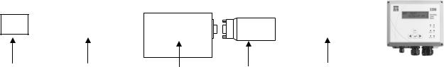
Front Panel
The front panel of the 5200 contains the display and keypad as shown in Figure 2-1 Front Panel.
|
DO 6.57 mg/L H |
5200 |
Hold indicator |
Display |
Recirculating |
DO LED |
|
|
Cond 7.63mS * |
Monitor |
|
|
|
System |
|
|
|
|
System Status |
Escape key |
|
|
LED |
|
DO System |
Temperature LED |
|
|
|
||
|
|
Status |
|
Enter key |
ESC |
Temperature pH |
pH LED |
|
|
||
Left Arrow key |
|
Conductivity ORP |
ORP LED |
|
|
Conductivity LED
Right Arrow key
Figure 2-1 Front Panel
The YSI 5200 is operated using tactile switches mounted behind the front overlay.
Key |
Name |
Main Display Function |
Menu Function |
|
|
|
|
[ ] |
Enter |
Enter main menu |
Pressing the Enter key confirms a selection and |
|
|
|
advances the menu. |
|
|
|
|
[ESC] |
Escape |
Hold display line |
Pressing the Escape key cancels a selection and |
|
|
|
backs the system one menu level. |
|
|
|
|
[f] |
Right Arrow |
Scroll display parameters |
Scrolls right to the next selection. |
|
|
forward |
|
|
|
|
|
[e] |
Left Arrow |
Scroll display parameters |
Scrolls left to the next selection. |
|
|
backwards |
|
|
|
|
|
YSI Incorporated |
6 |
5200 Recirculating System Monitor |
Status Lights
The 6 status lights located on the front panel of the 5200 (see Figure 2-1 Front Panel) indicate whether a system is operating within its preset limits or a control system has been activated.
Parameter Status Lights for Temperature, DO, pH, Conductivity and ORP are configured as follows: OFF – parameter not enabled
GREEN – normal range
FLASHING GREEN – control mode (turns off when it crosses the original set point)
RED – alarm (turned off by pressing any key, except escape, and resolving the alarm condition) The System Status LED is configured:
GREEN – normal operation RED – battery back-up
Flash Memory Architecture
A key feature of the YSI 5200 is that it is designed using FLASH memory allowing software updates to be easily accomplished. Refer to Section 9.1.5 Downloader (Upgrading Software) for instructions on upgrading the software in the YSI 5200.
Powering the YSI 5200
Primary power for the YSI 5200 is either a wall mount power transformer providing 8.5 to 16 VDC at 700 mA or any power source providing voltage and current in the stated operating range. The YSI 5200 comes standard with a 12VDC 700 mA wall mount power supply. In addition, an optional 12VDC battery backup input is available for powering the YSI 5200 should the primary power fail.
The YSI 5200 design incorporates FLASH Memory, RAM, and a battery backed-up real-time clock. Should power be lost, none of the parameter setpoints or configuration data will be lost. However, during a power failure, data in the data-log will be erased if no backup power is provided to the unit.
Control Capability
The YSI 5200’s software gives it the capability for parameter control as well as monitoring. Using the 4 built in control relays, a wide variety of monitoring and control features can be automatically activated.
The sensors gather information and relay it to the YSI 5200 controller. The 5200 can directly control devices through the four built-in relay outputs. Each device that the YSI 5200 controls, such as a heater or chiller, can be programmed
Timing System
The timing control feature allows the YSI 5200 to control external devices such as a lighting system. The timing system will support up to 4 independent control times per 24 hours. Each channel has one ON and OFF time per 24-hour period.
Alarm System
The alarm system provides visual and audible notification in the event that a monitored parameter exceeds the user defined range. Used in conjunction with the YSI 5201 modem (or a computer running AquaManager software and equipped with a compatible modem), it provides remote alarm notification
YSI Incorporated |
7 |
5200 Recirculating System Monitor |
via a digital pager. Used in conjunction with a computer running AquaManager Software, it provides email alarm notification.
Feed Timer System
The Feed Timer System allows control and monitoring of feedings made by the 5200. Optional Parameter control reduces the amount of food dispensed if the DO, temp or pH values are “out of range.” The optional FCR (feed conversion ratio) feature automatically increases the daily amount of food dispensed.
YSI Incorporated |
8 |
5200 Recirculating System Monitor |
Section 3. Installation
Installation includes the following sections:
Unpacking and Inspection
Selecting an Installation Location
Installing the Components
Mount the YSI 5200 Recirculating System Monitor
Installing the 5562 or 5561 Probe Assemblies
Wiring the System
Communications Method
Grounding Information
Safety Issues
Lightning and Surge Protection
3.1 Unpacking and Inspection
Inspect the outside of the shipping carton for damage. If damage is detected, contact the carrier immediately. Remove the instrument from the shipping container. Be careful not to discard any parts or supplies. Confirm that all items on the packing list are present. Inspect all assemblies and components for damage.
Save the original packing carton. Carriers typically require proof of damage due to mishandling. Also, if it becomes necessary to return the monitor, you should pack the equipment in the same manner it was received.
The following components are included with the purchase of the 5200 Monitor: 5200 Monitor
006515 Flange Mounting Kit
6506 Desiccant Kit
605226 Instruction Manual
605230 Compression Plugs, 2 each
605229 Compression Plugs, 2 each
655384 Dual Male RJ-45 Cable Assembly
655383 Adapter, DB-9 to RJ-45
655385 Inline Power Ferrite Assembly
655361 Ferrite Bead for Communication Port .390, .870, 1.272, 2 each 655365 Ferrite Bead for Relays, .500, 1.142, 1.280
605227UL 5579 (or 655478UL 5578) 12-Volt Power Supply 605223UL Pluggable Socket Connector for 12 VDC Power
605223UL Pluggable Socket Connector for RS-485, 4 Pole, with 120Ω termination resistor 065944UL Pluggable Socket Connector for Relays, 12 Pole
065942UL Pluggable Socket Connector for Auxiliary Inputs, 3 Pole
If any parts are damaged or missing, contact your factory representative or YSI immediately.
YSI Incorporated |
9 |
5200 Recirculating System Monitor |


 WARNING: To avoid severe personal injury or damage to the equipment, installation, operation and service should be performed by qualified personnel who are thoroughly familiar with the entire contents of this manual.
3.2 Selecting an Installation Location
The 5200 monitor is an on-line continuous measurement tool that can be used to control various operations and provide valuable insight into the facility’s operation. As with any instrument of this type, proper installation is the first important step to ensure you are provided with reliable performance and accurate data. Installation of the monitor and probe should be carefully planned in advance to obtain the most effective and accurate utilization of the equipment.
3.2.1Choosing a Probe Location
Probe location is determined by the necessity to obtain water quality readings which are representative of the bulk flow stream. A suitable location should take a number of physical and chemical factors into consideration. See Section 3.5 Installing the 5562 or 5561 Probe Assemblies.
Standard probe cable lengths for the 5200 are 4, 10 and 20 meters. Consider the entire distance required for cable routing when determining cable length requirements and mounting locations.
The probe must be located in the flow stream where the sensors will remain submersed at all times and level fluctuations will not expose them to the atmosphere.
The probe must be placed in a well mixed, free-flowing area of the process stream. The flow stream should be representative of the process being monitored/controlled. Placing the probe midstream and mid-depth typically gives the most reliable results.
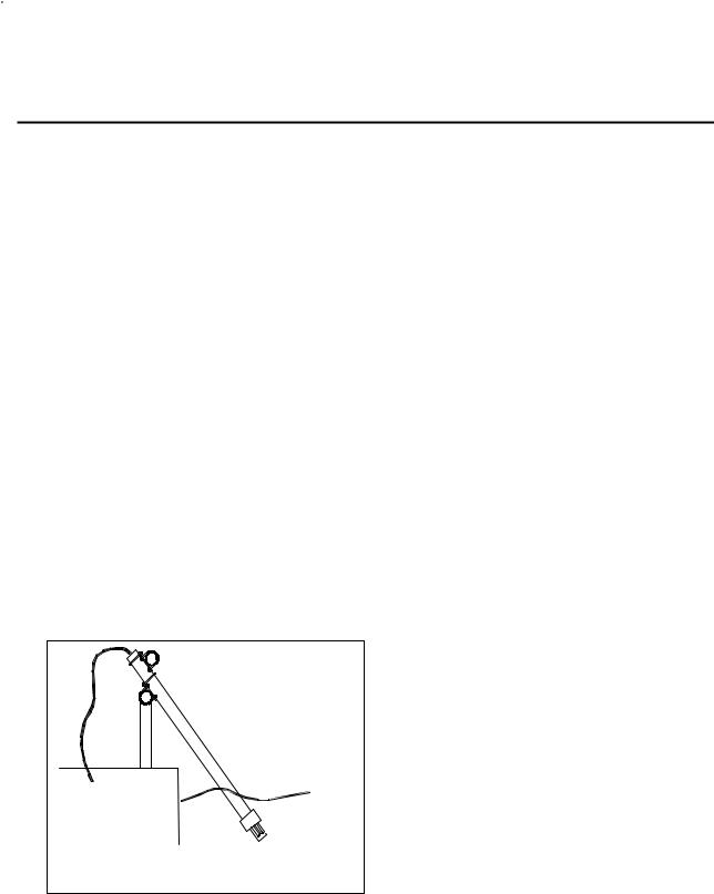
Ideally, the probe should be placed at an angle within 45° of vertical and directed with the flow direction (see Figure 3-1). This location will provide for the least stress on the support arm holding the probe while minimizing the opportunity to collect debris. Placement against the flow stream or perpendicular to the flow stream also provides accurate monitoring, but inspection and cleaning may be required more frequently due to increased collection of debris.
Not drawn |
Probe |
|
|
to scale. |
|
Figure 3-1 Probe orientation (using rail mount kit)
The flow stream should be as free as possible of debris (e.g., algae) which could collect on the probe and cause erroneous readings. See 3.5 Installing the 5562 or 5561 Probe Assemblies for flow requirements.
YSI Incorporated |
10 |
5200 Recirculating System Monitor |
Note that this is an on-line device that is measuring actual conditions in real time. Composite sampling for pH, for example, will not match on-line monitoring. Therefore, pH values recorded by the chart recorder and/or plant control system connected to the 5200 Monitor cannot be averaged to equal the pH of a composite sample.
3.2.2Choosing a Monitor Location
The probe measures conditions in the flow stream and transmits a low voltage signal to the 5200 Monitor. The probe is attached to a cable that is equipped with a “military grade” watertight connection to the monitor.
Several options are available for mounting the 5200 Monitor. Easy to use, wall mount brackets (006515 Flange Mounting Kit) are provided with the 5200. If rail or panel mounting is desired, the 6509 Rail Mount Kit and 6510 Panel Mount Kits are available as accessories.
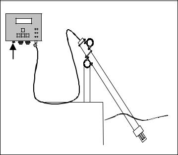
NOTE: The 5200 Monitor is provided with a weatherproof enclosure that will withstand most environmental conditions with no compromise to system performance. An optional Weather Shield (YSI #6505) is available for added protection from the elements. When mounting the 5200 outdoors the 6505 Weather Shield should be used.
5200 Monitor |
|
|
5200 |
DO 5.30 Mg/L |
Recirculating |
02/02/00 9:30PM |
MonitorSystem |
ESC |
|
|
|
DC |
|
|
Probe |
Not drawn to scale. |
|
|
Stream |
Figure 3-2 Monitor and probe installed using 6511 probe rail mount kit
Locating the monitor close to the sample location has advantages since accuracy checks and calibration can be more easily facilitated under this arrangement. For example, a recently calibrated, hand-held dissolved oxygen meter can be placed next to the 5200’s probe and readings can be compared.
Probe cables for the 5200 Monitor are available in 4 (13.1 ft), 10 (32.8 ft) and 20 (65.6 ft) meter lengths. The probe cable length determines the maximum distance the monitor can be mounted from the sample being measured.
Location of the 5200 Monitor should be elevated and in a dry place above the potential flood level. The unit should be easily accessible for an operator or technician.
Although the monitor is suitable for outdoor use, it should be located in an area where temperature extremes, vibrations, electromagnetic and radio frequency interference are minimal. Select an installation location that is at least two (2) feet from any high voltage conduit. Avoid mounting on severely vibrating
YSI Incorporated |
11 |
5200 Recirculating System Monitor |

structures or near a high heat source, AC motor or transformer, radio transmitter or antenna. Be sure the monitor can be fully opened and serviced at its installed location by maintenance personnel.
3.3 Installing the Components
There are three basic parts to installing the YSI 5200 Monitor, which are covered in the following sections:
Installing the YSI 5200 Monitor hardware and additional components Installing the probe assembly
Wiring the 5200 Monitor
3.3.1Sealants, Desiccants and Securing the Monitor
Since the 5200 Monitor will likely be subjected to environmental conditions that promote formation of condensation, it is very important to follow the instructions below before securing the cover to your unit(s). This will prevent damage to the electronic components within the Monitor and extend the life of the monitoring system.
The 5200 Monitor is shipped with three compression fittings. The small compression fitting on the left side of the bottom panel is to be used for the power supply wire. The two larger compression fitting are supplied with solid plugs installed. These solid plugs should be left in place if no other electrical connections are to be made to the 5200.
If electrical connections are required for control relays, PC connections or other devices, there are a number of options to ensure a watertight installation to the 5200’s case.
1.Solid plugs, located in the 2 larger compression fitting, can be frozen (put in a freezer for 1 hour) and then easily drilled to the required diameter. The drill bit diameter should be slightly smaller than the wire diameter so that a watertight seal can be made.
2.Compression plugs with two different pre-sized holes are supplied with the 5200 Monitor. The hole size in the plugs varies with the amount of torque applied to the compression nut. To install a predrilled plug, the solid plug can be “pushed out” of the compression fitting housing and the pre-drilled plug installed.
3.Optional conduit fittings (YSI #065926) can be installed in place of the compression fittings. When using conduit fittings, industrial encapsulant (YSI #065921 conduit sealer) must be used to prevent moisture from entering the 5200 monitor. After all wiring and connections are complete, apply the sealant to the conduit openings from the inside of the 5200 Monitor. Failure to use industrial encapsulant may result in damage to the 5200 Monitor.
Also included with the 5200 Monitor is a desiccant pack, YSI #6506. Desiccant absorbs moisture captured within the enclosure. After all wiring and connections are complete (just before the cover is to be installed), place the desiccant pack inside the 5200 enclosure near the bottom right corner. Remove the desiccant from its protective packet prior to installation.
Secure the monitor’s cover using four mounting screws. Note that the cover contains a captured rubber gasket that provides weatherproofing. Make certain that the gasket is in place and not twisted or damaged. Make certain that the large blue ribbon cable is not trapped in the gasket channel before inserting the screws. When securing the screws, take care not to cross thread. The screws are stainless steel, and the receiving threads are brass. Do not over-tighten!

 CAUTION: Anytime the 5200 cover is removed, replace the desiccant pack with a new pack. Anytime the 5200 front panel is removed, place it on top of the 5200 Monitor or secure it so that the blue ribbon cable does not bear the weight of the cover.
YSI Incorporated |
12 |
5200 Recirculating System Monitor |

3.3.2Installation Check List
9Determine optimum mounting location for the probe based on the parameters being measured and/or controlled
9Determine optimum mounting location for 5200 Monitor
9Fabricate probe mounting plate if necessary
9Mount the probe
9Connect the probe to the monitor
9Make wiring connections for relays
9Make wiring connections for communication ports
9Make wiring connections for DC power
9Make ground wiring connections
9Verify that all wiring connections are secure
9Apply industrial encapsulant to conduit fittings-if applicable
9Insert desiccant pack(s) into 5200 Monitor
9Reinstall front cover to 5200
9Recheck grounding and surge protection installations
9Allow probe circuitry and sensors to warm up for several minutes
9Calibrate the probes and program the monitor’s software
9Place calibrated probe in mounting fixture
3.4 Mount the YSI 5200 Recirculating System Monitor
Several options are available for mounting the 5200 Monitor. Easy to use, wall mount brackets (6515 Flange Mounting Kit) are provided. If rail or panel mounting is desired, the 6509 Rail Mount Kit and 6510 Panel Mount Kits are available as accessories.
3.4.1Wall Mounting Option
Although the monitor is designed for outdoor deployment, some operators may prefer the convenience of reading the monitor under shelter, for example, inside a nearby building. Figure 3-4 shows this indoor type of installation. Wall-mounting the 5200 Monitor is a simple process using the enclosed 006515 mounting hardware.
YSI Incorporated |
13 |
5200 Recirculating System Monitor |

The following steps should be followed when wall mounting the 5200 Monitor.
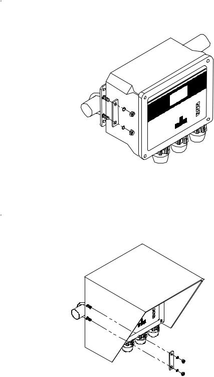
1.Loosely fasten the mounting brackets (included) to the back of the 5200 Monitor with the mounting screws provided as shown in Figure 3-3.
2.Tighten the screws, securing the brackets to the Monitor.
3.Loosely fasten the 5200 Monitor to the mounting surface with the mounting screws provided as shown in Figure 3-4.
4.Tighten the screws, securing the Monitor to the surface.
Figure 3-3 Attaching the Mounting Brackets
Figure 3-4 Securing the screws to the mounting surface
YSI Incorporated |
14 |
5200 Recirculating System Monitor |
3.4.2Optional 6509 – Rail Mount Kit
The 5200 Monitor can be easily mounted to pipe or handrail (1 to 1½ inch diameter) using the optional 6509 Rail Mount Kit. When using the 6509 Rail Mount Kit, the 006515 mounting flanges will have to be modified by drilling two holes to accept the u-bolts. The predrilled metal plates can be used as a template.

 CAUTION: The monitor should not be mounted on electrical conduit, a hot or vibrating pipe or structure, or near a high heat source, an AC motor, transformer, radio transmitter or antenna.
3.4.3Optional 6505 – Weather shield
The Weather Shield provides wall or optional rail mounting capability for the 5200 Monitor.

 CAUTION: The monitor should not be mounted on electrical conduit, a hot or vibrating pipe or structure, or near a high heat source, an AC motor, transformer, radio transmitter or antenna.
YSI Incorporated |
15 |
5200 Recirculating System Monitor |

3.4.4Optional 6510 – Panel Mount Kit
Panel mounting the 5200 Monitor is a simple process using the 6510 Panel Mount hardware and the following tools; 5/32” Allen wrench, Philips screwdriver, and the necessary tools for cutting the mounting hole in the control panel. The 5200 Monitor may be mounted in any panel with 9.5”L x 7.5”W space available, and behind the panel depth of 5.5”.
YSI Incorporated |
16 |
5200 Recirculating System Monitor |

3.5 Installing the 5562 or 5561 Probe Assemblies


 CAUTION: Keep pH and ORP probe tips IN A MOIST ENVIRONMENT at all times.
After you have chosen suitable sites for the monitor and probe, proceed with the probe installation as described below.
Avoid routing probe cabling near wiring associated with rotating machinery and/or equipment involving electrical switching or regulation. In all cases, it is desirable to locate the probes away from sources of electrical interference such as UV sterilizers, florescent lighting, ballasts, pumps, etc. Consider placing probe cabling in grounded metallic conduit if unstable readings appear due to electromagnetic interference.
The 5200 can be configured with either a 5562 multiprobe assembly (DO, Conductivity, Temperature, and optional pH or pH/ORP sensors) or a 5561 DO/Temp probe assembly.
NOTES: When the 5200’s control functions are to be used, probe placement will be critical to the operation of the system. Consequently, a professional should be consulted when designing the system.
Water flow is important to the operation of the DO sensor. In addition, the mixing action provided by water flow ensures that the area of sampled water is representative of the entire body of water.
Probe installation steps:
1.Select a suitable location for the probe assembly that allows for adequate water flow across the DO sensor (approximately 0.5 ft/sec).
2.Select a method of securing the probe assembly.
3.Determine a method of routing and securing the cable.
In-Filter Location— A common place for probe location is in the filter. Installing probes in a filter or sump requires that the probe be secured or hung in an area that will allow for adequate water flow across the DO sensor (approximately .5 ft/sec).
In-Filter Location Using a Float—A float installation keeps probes at a constant depth, and is economical to purchase or construct.
To construct a probe float, cut a hole (slightly smaller than the probe diameter) through a small piece of Styrofoam. Insert the probe into the float so that the entire sensor guard protrudes through the Styrofoam and the sensors are completely submerged.
In-Tank Location—Installing the probe assembly in a tank requires that the assembly be secured or hung in an area that will allow for adequate water flow across the DO sensor (approximately 0.5 ft/sec). It is preferred that the probe be secured so that the cable is not constantly flexed.
If using the 5562, the probe assembly can be secured using the 5205 Probe Mounting Kit or 6511 Probe Rail Mount Kit. See Section 3.5.2 5205 and 6511 – Optional Probe Mount Kits for 5562 Probes. A mounting kit is not available for the 5561 probe.
In-Line Location Using a Tee-Fitting—Although in-line probe placement is more time consuming and requires some extra plumbing, it has been found to be a very effective and safe way to place probes. Inline placement gives accurate readings because water is moving across the probe tips at all times. It also minimizes biological growth on the sensors.
IMPORTANT NOTE: When maintenance and/or calibration of the sensors is required, the probe assembly will have to be removed from the in-line fitting. Take this into account when designing the system. If water flow must be maintained during maintenance, by-pass plumbing will be required.
YSI Incorporated |
17 |
5200 Recirculating System Monitor |

For this type of installation, the probe guard is removed and the probe is threaded into a tee-fitting using the probe guard’s threads. All probes need to be placed into the flow stream. YSI does not provide tee fittings for this type of installation.
Thread size for 5562 multiparameter probe assembly: 1.50-12 UNF 2A Thread size for 5561 DO/Temp probe assembly: ¾-27 Class 2 thread
In–Line Location Using A Flow Cell (5562 Probe only) – The 5083 Flow Cell can be connected anywhere in the pumping system where a water flow rate of 2–3 L/minute can be obtained. Maximum pressure rating for the 5083 is 25 psi. A portion of water from a pump discharge line can be diverted through the 5083 Flow Cell, or a method with a designated pump can be utilized.
3.5.25205 and 6511 – Optional Probe Mount Kits for 5562 Probes
NOTE: The 6511 kit includes Clamps for Rail Mounting. The 5205 Kit does not include mounting hardware.
2” Schedule
40 PVC
Stop
Probe
Guard 
Figure 3-5 Probe Mounting Kit
5205 and 6511 Probe Mount Kits allow a 5562 Probe to be deployed in a permanently mounted two-inch schedule 40 PVC tube. The schedule 40 PVC is not included in the kit. Once installed, the probe is deployed by gently sliding it down the tube, where it will rest on a stop cap at the end of the tube. The sensors and probe guard will protrude through a hole in the stop cap at the end of the tube. See Figure 3-5.
When mounting to a 1–1½″ railing, the 6511 kit should be used. It includes brackets and u-bolts for rail mounting and a stop cap and adaptor. See Figure 3-5.
When mounting to structures other than 1–1½″ railing, a 5205 kit should be used. When using the 5205 kit, the installer must develop a method of mounting the 2″ PVC tube to a permanent structure. The 5205 kit consists of a stop cap and adapter and does not include mounting hardware.
The 5205 and 6511 Kits should not be mounted on hot or vibrating pipes or structures, or near high heat sources, AC motors or transformers, radio transmitters or antennas.

 CAUTION: Do not mount on electrical conduit.
YSI Incorporated |
18 |
5200 Recirculating System Monitor |
Set Screw
2” PVC Tube
Adapter
Probe Guard
5562 Probe Body |
Stop Cap |
Figure 3-6 Adapter Position
The following steps should be followed when mounting the 5205 or 6511 Probe Mount Kit.
1.With the 3 setscrews removed from the adapter, slide the adapter over the 5562 Probe. Align the open screw holes directly over the 3 hex bolts located on the side of the 5562 Probe.
2.Insert the setscrews so that they seat into the head of the probe’s hex bolts.

 CAUTION: Do not over-tighten the setscrews or damage to the probe body or adapter may occur.
NOTE: The 5562 Probe Assembly can be deployed without the probe guard attached. When doing so, application related precautions must be considered or system performance can be compromised. Deployment without the guard is preferred as the effects of low water flow and fouling are reduced, but exposed sensors or the DO membrane, can be damaged if not properly protected.
3.Attach the stop cap to the end of a PVC pipe using PVC cement, as per instructions on the cement can label, ensuring that the stop cap is positioned straight and the pipe is fully inserted.
4.5205 Only: Firmly mount PVC pipe to permanent structure. Skip to Step 9.
5.Loosely fasten two 1½” u-bolts on each mounting plate to the railing, orientated as shown in Figure 3-7.
1.5” U-Bolts
2” U-Bolts |
Mounting |
Plates |
Figure 3-7 6511 U-Bolt Mounting
6. Loosely attach the 2” u-bolts to the mounting plates, orientated as shown in Figure 3-7.
YSI Incorporated |
19 |
5200 Recirculating System Monitor |

7.Slide the uncapped end of the PVC pipe up through the 2” u-bolts until there is approximately 1” of the PVC pipe above the upper mounting plate, and tighten 2” u-bolts. Note: Do not over tighten u-bolts or deformation of the PVC pipe may occur.
8.Tighten all remaining u-bolts to secure pipe.
9.Slowly slide the 5562 Probe/Adapter Assembly down the PVC pipe until it rests on the Stop Cap.
10.Connect the cable to the 5200 Monitor.
3.6 Wiring the System


 WARNING: All wiring involving connections to mains power must be performed by a qualified licensed electrician, and must conform to all locally applicable electrical codes. Any mains power circuit connected within the YSI 5200 enclosure must be protected by a Ground Fault Circuit Interrupt device. Do not make connections while power is applied. Disconnect power before proceeding.

 WARNING: The 5200 utilizes sensitive solid-state devices that can be damaged by static shock. Installers must observe accepted ESD (Electro-Static Discharge) procedures while connecting cabling to the 5200 I/O plate or damage may result.
The 5200 Monitor has one MS-19 connector and three compression fittings in the bottom of the monitor housing. The two larger compression fittings can be replaced with ¾ inch conduit fittings. From a front view, the smaller compression fitting on the left is for 12-volt power. The opening on the right is for communications and I/O wiring and the center opening is for relay wiring.
NOTE: The 5200 Monitor is supplied with components necessary to make reliable electrical connections. When received, pluggable sockets are installed in the power, relay, RS485 and auxiliary ports. These sockets are to be unplugged prior to making electrical connections and reinstalled after connections are made.

 CAUTION: It is essential that all sensor wiring be run in a separate cable or conduit from power wiring.
12VDC Primary and Back-up Power Connector
Connect to earth ground
Control Relays
(4) soldered to PCB
POWER IN 12V, 1A MAX
(+)-- |
(-)-- |
(+)-- |
(-)-- |
MAIN |
COM |
BACKUP |
COM |
|
|
|
|
YSI MODEL 5579 |
12V BATTERY FUSE |
REQUIRED, 1A MAX |
|
|
|
|
Relay Outputs |
1 |
2 RELAYS3 |
4 |
NETWORK |
N.C.-- COM-- N.O.-- N.C.-- COM-- N.O.-- N.C.-- COM-- N.O.-- N.C.-- COM-- N.O.-- |
T(-)-- T(+)-- R(-)-- R(+)-- |
||
FOR LOAD CONNECTIONS USE
WIRE SUITABLE FOR 90°C
SERIAL IP PORT
GND--
IN 2 --
IN 1 --
RS485 5200
Network Connector
RS232 and TCP/IP Serial Connector (RJ-45)
Aux. Analog and
Digital Input
Connector
Figure 3-8 I/O Plate
YSI Incorporated |
20 |
5200 Recirculating System Monitor |

Figure 3-9 Placement of Ferrites and Pluggable Sockets
3.6.1DC Power Input Wiring
12VDC power for the 5200 Monitor may be supplied by the YSI 5578/5579 power supply accessory provided with the unit, or by a 12VDC source supplied by the user.


 CAUTION: The YSI 5578/5579 power supply accessory is for indoor use only, and must be connected to the 5200 Monitor with a suitable waterproof extension cable if the 5200 Monitor is installed in a damp location.
For outdoor or damp locations, the YSI 5578/5579 power supply may also be installed in a NEMA 4X enclosure adjacent to the 5200.
3.6.2Installing the 5578/5579 Power Supply
When using the 5579 power supply it should be wired as follows: (see Figure 3-9)
•Connect the Inline Power Ferrite Assembly, YSI# 655385, to the I/O plate power connector. Failure to do so could cause catastrophic monitor failure.
•Route the 5578/5579 power supply wire through the small compression fitting and into the case.
•Connect the 5578/5579 wires to the 4-pole 605223UL Pluggable Socket Connector so that the white wire goes to Main (+) and black wire to Common (-).
•Connect the 4-pole 605223UL Pluggable Socket Connector to Inline Power Ferrite Assembly.
•Tighten compression fitting. See Section 3.3.1 Sealants, Desiccants and Securing the Monitor.

 WARNING: A UL Listed DC power supply is required for any installation which is connected to “mains
YSI Incorporated |
21 |
5200 Recirculating System Monitor |

supply” or other power source which is “hazardous live” per UL 3101-1 Section 3.5.2.
The 5200 Monitor may be powered by any regulated 8.5–16.5 VDC source that can provide approximately 800mA of current and is isolated from mains supply by double or reinforced insulation. (An unregulated supply may also be acceptable if the peak output voltage does not exceed 16.5VDC.)

 WARNING: A UL Listed slow-blow fuse with a maximum current rating of 1A must be connected in series with the positive terminal of any power supply not provided by YSI.


 CAUTION: Power supply voltage above 16.5VDC may permanently damage the 5200 Monitor.
When the front panel of the 5200 Monitor is removed, take care not to drop the cover since it is not hinged to the Monitor.


 CAUTION: The sensitivity and stability of the monitor will be impaired if the monitor is not grounded. Do not apply power to the Monitor until all electrical connections are verified and secure. Connect earth ground to the 5200 I/O plate (see Figure 3-8 I/O Plate).
3.6.3Back-up Power

 WARNING: A UL Listed slow-blow fuse with a maximum current rating of 1A must be connected in series with the positive terminal of the back-up supply.
The 5200 Monitor will automatically switch to auxiliary battery back-up operation if primary voltage drops below 8.5 VDC, providing back-up power is connected. For proper back-up power operation, use the YSI 5578/5579 Power Supply as the primary power source. Use of a different primary power supply may prevent proper switching to back-up power.

 WARNING: A UL Listed DC power supply is required for any installation which is connected to “mains supply” or other power source which is “hazardous live” per UL 3101-1 Section 3.5.2.
The auxiliary power source is user supplied and can come from a variety of choices including lead acid or gel cell external batteries. The 5200 will not charge batteries, so quality assurance maintenance procedures must be established if batteries are used as the back-up power source.
Input power requirements for back-up operation are the same as primary power, 8.5–16.5 VDC at approximately 800mA. With no primary power, when the back-up voltage falls below 7.0 volts the 5200 will cease to operate properly.
Connecting back-up power to the 5200 Monitor
Refer to Figure 3-9.
•If necessary, disconnect power to the 5200 Monitor
•Route the back-up supply wire through the compression fitting and into the case. See Section 3.3.1 Sealants, Desiccants and Securing the Monitor.
•Connect the back-up wires to the 4-pole 605223UL Pluggable Socket Connector so that the positive wire goes to the Back-up (+) terminal and the negative wire goes to the Common (-) terminal.
•Connect the 4-pole 605223UL Pluggable Socket Connector to Inline Power Ferrite Assembly. Failure to do so could cause catastrophic monitor failure.
•Connect the Inline Power Ferrite Assembly to the I/O plate power connector.
IMPORTANT: After completing system installation, test back-up power by removing main power while all control/alarm relays are energized. At cold temperatures, logged data may be lost due to temporary power loss when switching to battery backup power.
YSI Incorporated |
22 |
5200 Recirculating System Monitor |


 CAUTION: The sensitivity and stability of the monitor will be impaired if the monitor is not grounded. Do not apply power to the Monitor until all electrical connections are verified and secure.
3.7 Communications Method
The 5200 has three methods of communication:
RS232 TCP/IP Serial Port—to directly connect with a computer or network Modem—to communicate with a computer or pager via phone line
RS485 Network—to directly connect with other 5200s
3.7.1RS232 and TCP/IP Port
RS232 serial and TCP/IP communications are made through the TCP/IP port. This port can be permanently connected to a PC or network for continuous monitoring applications, or to the 5201 Modem sending alarm messages via phone. The RS232/TCP/IP port uses a standard RJ-45 connector.
Two snap on ferrite assemblies, YSI# 655361, are included with the 5200 Monitor. Wires being connected to the communication port need to be routed through the ferrites as shown in Figure 3-9. Failure to do so could cause catastrophic monitor failure.
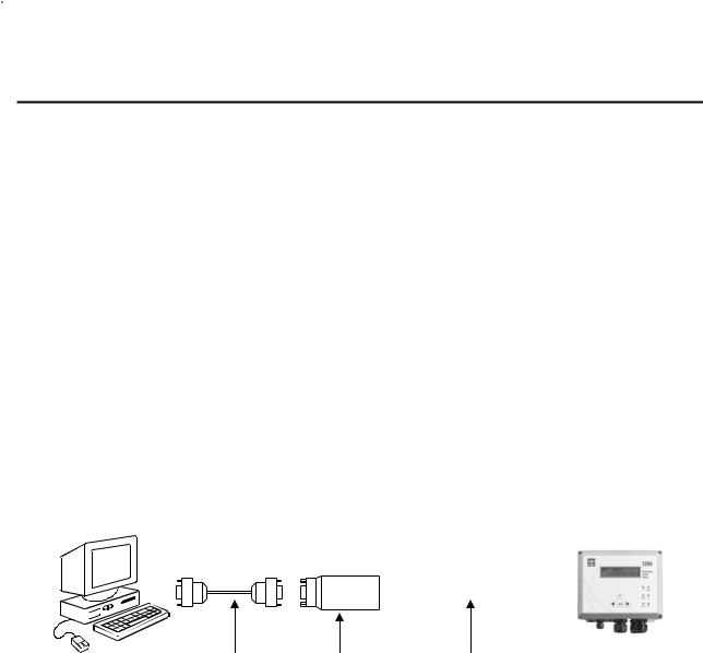
RS232 PC Connection
When connecting the 5200 via the serial port to a PC for continuous operation, use an inline RS232 OptoIsolator device (YSI# 5285 or equivalent) to prevent ground loops. Failure to use this device may cause incorrect DO, pH, ORP and conductivity data to be displayed and logged. Mount the isolator as close to the PC as possible or in an area where it is protected from moisture.
|
|
|
|
|
|
|
|
|
|
|
|
|
|
|
|
|
|
|
|
|
|
|
|
|
|
|
|
|
|
|
|
|
|
|
|
Computer |
DB9 RS232 |
YSI 5285 |
RJ-45 Straight-through |
5200 Monitor |
|||||||
|
|
|
|
|
|
|
|
Serial Cable |
Opto-Isolator |
Cat 5 network cable |
|
RS232 Serial Connection to a PC
When making RS232 cable runs greater than 100 feet (30.5 meters), use an RS232 Line Extender/Booster. Not using this device may cause communication failures. Mount the booster in an area where it is protected from moisture.
When temporarily connecting the 5200 to a PC, a “Straight-Pinned” Dual Male RJ-45 cable and a DB-9 to RJ-45 Adapter (YSI# 655383) wired as in the chart below are required.
YSI Incorporated |
23 |
5200 Recirculating System Monitor |
Wiring Diagram for DB-9 to RJ-45 Adapter
|
|
Wire color internal to |
DB-9 pin # |
Signal name (from 5200) |
RJ-45 pin # |
adapter (may change |
|
|
|
based on supplier) |
|
TX (232TXD) |
4 |
Red |
3 |
RX (232RXD) |
5 |
Green |
2 |
Common (DGND) |
6 |
Yellow |
5 |
CTS (232CTS) |
7 |
Brown |
8 |
DTR (232DTR) |
8 |
Gray |
4 |
Supplied with the 5200 are a YSI# 655384 Straight-pinned Cat 5 EIA568 compliant network patch cable and pre-wired YSI# 655383 RJ-45 to DB-9 Adapter. The supplied cable and adapter are only intended to be used for software upgrades or downloading data. Do not use this cable for long-term installation as the compression fitting cannot form a proper seal. See Section 3.3.1 Sealants, Desiccants and Securing the Monitor.
Bulk cable for permanent installations must be round (to allow the compression fitting to seal) and should be purchased locally. A crimping tool will be required to install RJ-45 connectors to each end of the cable.
IMPORTANT: 1. The connector that is to connect inside the case should be crimped after the cable is run through the compression fitting.
2. Round cable must be used so a watertight seal at the compression can be achieved.
TCP/IP LAN Connection
An Ethernet serial server is required to connect the 5200 to a LAN. The serial server must be assigned a static IP address.
LAN
Ethernet |
RJ-45 Straight-through |
Ethernet Serial |
DB9 to RJ-45 |
RJ-45 Straight-through |
5200 Monitor |
network |
Cat 5 network cable |
Server |
adapter |
Cat 5 network cable |
|
TCP/IP Connection to a LAN
Additional RS232 TCP/IP Wiring Information
The 5200 uses a symmetrical EIA-232 data terminal equipment (DTE) pinout on the RJ-45 serial port. Table 3-1 lists the pinouts of the RJ-45 ports used for EIA-232 serial communications.
YSI Incorporated |
24 |
5200 Recirculating System Monitor |

RJ-45 Pin |
RS232 |
Direction |
RS232 |
TCP/IP |
|
Signal Function |
Number |
Name |
|
|
|
|
|
|
|
|
|
|
|
|
1 |
DCD |
I |
NC |
P |
|
Signals module that remote device is |
|
|
|
|
|
|
attached and powered on |
|
|
|
|
|
|
|
2 |
RTS |
O |
NC |
P |
|
Flow control, to enable remote device to |
|
|
|
|
|
|
send data |
|
|
|
|
|
|
|
3 |
SG |
|
P |
P |
|
Signal return (NOT chassis ground) |
|
|
|
|
|
|
|
4 |
TXD |
O |
P |
P |
|
Serial data out, from YSI-5200 to remote |
|
|
|
|
|
|
device |
|
|
|
|
|
|
|
5 |
RXD |
I |
P |
P |
|
Serial data in, from remote device to YSI- |
|
|
|
|
|
|
5200 |
|
|
|
|
|
|
|
6 |
SG |
|
P |
P |
|
Signal return (NOT chassis ground) |
|
|
|
|
|
|
|
7 |
CTS |
I |
NC |
P |
|
Flow control, to enable YSI-5200 to send |
|
|
|
|
|
|
data on TXD |
|
|
|
|
|
|
|
8 |
DTR |
O |
NC |
P |
|
Signals remote device that YSI-5200 is |
|
|
|
|
|
|
attached and powered on |
|
|
|
|
|
|
|
|
|
|
|
Table 3-1 |
|
|
To connect the 5200 to an EIA-232 device, it needs to be determined if the device connector wiring follows the standard for data terminal equipment (DTE) or for data communication equipment (DCE). In general, modems are wired as DCE devices and all other devices are wired as DTE; however, some equipment manufacturers may deviate from the standard. In most cases, you use "straight through" RJ-45 cable. If you use "crossover" RJ-45 cable, the RJ-45 pins will be reversed.
3.7.25201 Modem
The YSI 5201 Modem is available only for use within the United States. For modem support outside the US, an external modem registered for use within the local country is required. See Section 17
International Modem Support.
The YSI 5201 Modem mounts inside the 5200 case and connects to the RS232/TCP/IP Port. Refer to the
5201 Modem Installation Instructions, included with the modem, for details.

 CAUTION: The phone line entering the 5200 case must be #26 AWG wire and must be sealed where it enters the case or the instrument may be seriously damaged.

 CAUTION: The ground wire from the 5201 Modem must be connected to the ground screw on the 5200 I/O plate.
3.7.3RS485 Network
Connecting 5200s via the RS485 network is described in 8.1 RS485 Network.
YSI Incorporated |
25 |
5200 Recirculating System Monitor |

3.8 Grounding Information
This section contains important installation information regarding grounding of the 5200 Monitor. Connect earth ground to the 5200 I/O panel as described below in 3.9 Safety ISSUES.
The probe is powered by the 5200 Monitor and will be operated with a “floating” ground reference. This requires that the probe not be individually grounded. Grounding the probe individually will cause a “ground loop”; i.e. one conductor of the probe output grounded common to both the probe and the monitor. Grounding the probe will cause significant performance problems with the sensors and likely result in erroneous readings.


 CAUTION: Do not ground the probe body.
All tanks should be electrically grounded via a ground probe.
3.9 Safety Issues
The electrical system must be grounded via the I/O plate to avoid possible electrical shock or damage to the equipment (see Figure 3-8 I/O Plate).

 WARNING: Turn off all power and assure power “lockout” before servicing to avoid contact with electrically powered circuits.
To avoid possible electrical shock, do not touch other circuit components when making adjustments to the 5200 Monitor circuit board. Disconnect external power to the unit before connecting or disconnecting wiring.
3.10 Lightning and Surge Protection
Surge protectors are strongly recommended to protect from secondary surges and lightning on outdoor installations.
Surge suppression devices should be located on the AC line supplying power to the 5200 Monitor and any signal lines connecting the 5200 Monitor.
AC line voltage surge suppressors protect field equipment on any AC line to ground from damage due to electrical transients induced in the interconnecting power lines from lightning discharges and other high voltage surges. The unit should include noise filtering, common mode and normal mode suppression and nanosecond reaction time. Surge suppressors should be internally fused to remove the load if the unit is overloaded or the internal protection fails.
Signal line suppressors protect low voltage signals and relay outputs from damage due to electrical transients induced in the signal lines from lightning discharges or nearby electrical devices. Signal line suppressors should be installed at each end of an analog loop. Relay outputs should be protected at the receiver end. Signal line suppressors should consist of a three-element gas tube followed by metal oxide varistors and suppressor diodes. The protective elements should be matched such that high-energy surge voltages trigger the gas surge arrester, while low energy or surge voltages affect the MOV’s and suppressor diodes.
Lightning protection devices should be located as close to the monitor as possible and wired in accordance with the National Electric Code in approved watertight enclosures.

 CAUTION: This or any other installation procedure cannot protect against a direct lightning strike. YSI Incorporated cannot accept liability for damage due to lightning or secondary surges.
YSI Incorporated |
26 |
5200 Recirculating System Monitor |
Section 4. Probe Module
Probe Module covers the following: Unpacking the Probe Module
Features of the YSI 5561 Probe Module
Features of the YSI 5562 Probe Module
Preparing the YSI 5561 Probe Module
Preparing the YSI 5562 Probe Module Membrane Cap Installation Calibration/Storage Cup (5562 only) Instrument/Cable Connection
Two different probe modules are available for the YSI 5200 Recirculating Monitor. The YSI 5561 Probe module is used for measuring dissolved oxygen and temperature only, while the YSI 5562 Probe module is used for measuring dissolved oxygen, temperature, conductivity, and optional pH or pH/ORP. A 4, 10 or 20 meter cable is directly connected to the probe module body making it waterproof.
4.1Unpacking the Probe Module
1.Remove the Probe module from the shipping box(es). NOTE: Do not discard any parts or supplies.
2.Use the packing list to ensure all items are present.
3.Visually inspect all components for damage.
NOTE: If any parts are missing or damaged, contact your YSI Service Center immediately. Refer to Section 14 WARRANTY AND SERVICE INFORMATION or www.ysi.com/environmental.
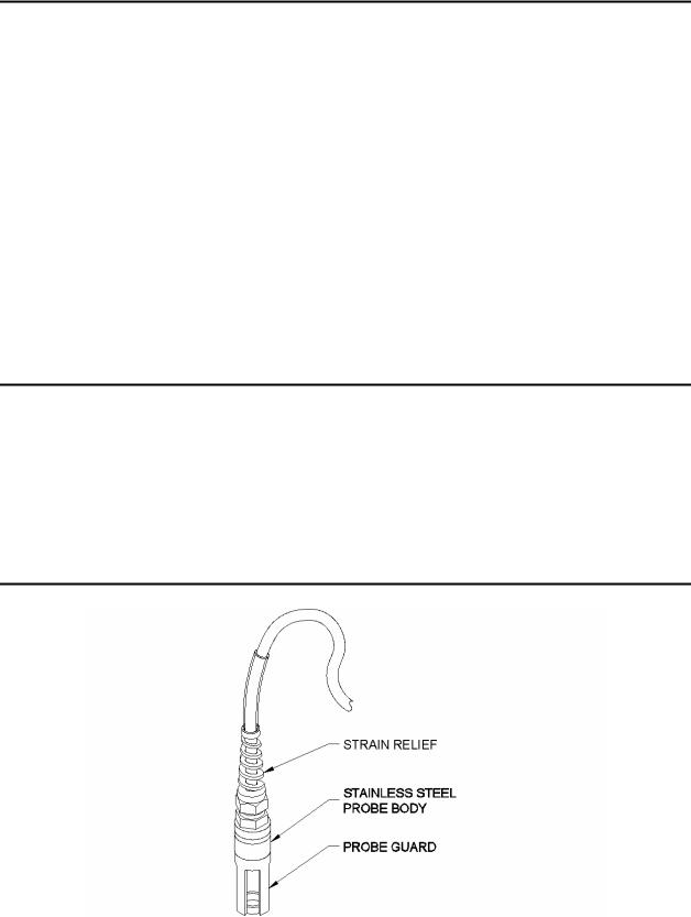
4.2Features of the YSI 5561 Probe Module
Figure 4-1 5561 Probe Module
YSI Incorporated |
27 |
5200 Recirculating System Monitor |

4.3 Features of the YSI 5562 Probe Module
|
Strain Relief |
|
Cable |
Metal Probe |
|
Connector Nut |
||
|
||
|
pH/ORP Probe |
Dissolved Oxygen
(DO) Probe
Conductivity/Temperature
Probe
Calibration/ |
Detachable Weight |
|
|
Storage Cup |
Probe Sensor Guard |
|
Figure 4-2 5562 Probe Module
4.4 Preparing the YSI 5561 Probe Module
To prepare the YSI 5561 Probe Module for calibration and operation, you need to install a new DO membrane cap. Refer to Section 4.6 Membrane Cap Installation for details.
4.5 Preparing the YSI 5562 Probe Module
To prepare the YSI 5562 Probe Module for calibration and operation, you need to install the sensors into the connectors on the probe module bulkhead. In addition to sensor installation, you need to install a new DO membrane cap.
4.5.1Sensor Installation
Whenever you install, remove or replace a sensor, it is extremely important that the entire probe module and all sensors be thoroughly dried prior to the removal of a sensor or a sensor port plug. This will prevent water from entering the port. Once you remove a sensor or plug, examine the connector inside the probe module sensor port. If any moisture is present, use compressed air to completely dry the connector. If the connector is corroded, return the probe module to your dealer or directly to YSI Customer Service. Refer to Section 14 Warranty and Service Information.
Conductivity/Temperature and pH, pH/ORP Sensor Installation
1.Unscrew and remove the probe sensor guard.
2.Using the sensor installation tool supplied in the YSI 5511 maintenance kit, unscrew and remove the sensor port plugs.
YSI Incorporated |
28 |
5200 Recirculating System Monitor |
Loading...