


 Loading...
YSI Environmental
P u r e D a t a f o r a H e a l t h y P l a n e t . ™
YSI 650 MDS
Multiparameter Display System
Operations Manual
YSI Incorporated |
2 |
650 MDS |
TABLE OF CONTENTS
SECTION 1 INTRODUCTION |
5 |
|
SECTION 2 GETTING STARTED |
5 |
|
2.1 |
UNPACKING |
6 |
2.2 |
UNDERSTANDING THE 650 MEMORY |
6 |
2.3 |
650 CONFIGURATIONS |
7 |
2.4 |
650 FEATURES |
10 |
2.5 |
BATTERIES AND CHARGING |
11 |
2.6 |
TURNING THE INSTRUMENT ON |
14 |
2.7 |
ADJUSTING THE DISPLAY CONTRAST |
15 |
2.8 |
USING THE 650 KEYPAD |
16 |
2.9 |
CONNECTING TO A SONDE |
19 |
2.10 UNDERSTANDING THE STATUS BAR |
21 |
|
2.11 UPGRADING ECOWATCH FOR WINDOWS SOFTWARE |
22 |
|
SECTION 3 SETTING UP THE 650 |
22 |
|
SECTION 4 SONDE MENU INTERFACE |
25 |
|
4.1 |
INTRODUCTION |
25 |
4.2 |
SONDE MENU EXAMPLES |
27 |
4.3 |
COMMON OPERATIONS USING 650 SONDE MENU SELECTION |
29 |
SECTION 5 LOGGING DATA WITH THE 650 |
31 |
|
5.1 |
INTRODUCTION AND BASICS OF LOGGING |
31 |
5.2 |
LOGGING DATA TO SONDE MEMORY |
33 |
5.3 |
LOGGING DATA TO 650 MEMORY |
37 |
5.4 |
650 LOGGING – “CANS” AND “CAN’TS” |
48 |
SECTION 6 MANAGING 650 FILES |
50 |
|
6.1 |
INTRODUCTION |
50 |
6.2 |
DIRECTORY |
51 |
6.3 |
UPLOAD TO PC |
52 |
6.4 |
VIEW FILE |
53 |
6.5 |
FILE MEMORY |
54 |
6.6 |
DELETE ALL FILES |
54 |
SECTION 7 UPLOADING DATA FROM SONDES |
55 |
|
7.1 |
INTRODUCTION |
55 |
7.2 |
UPLOAD PROCEDURE |
55 |
SECTION 8 USING GPS WITH THE 650 |
55 |
|
8.1 |
SETTING UP THE GPS-650 INTERFACE |
55 |
8.2 |
LOGGING GPS READINGS |
56 |
SECTION 9 USING THE 650 BAROMETER |
57 |
|
9.1 |
PRINCIPLES OF OPERATION |
57 |
9.2 |
CALIBRATING THE BAROMETER |
57 |
9.3 |
CHANGING BAROMETER UNITS |
58 |
9.4 |
LOGGING BAROMETER READINGS |
58 |
SECTION 10 UPGRADING 650 SOFTWARE |
59 |
|
SECTION 11 TROUBLESHOOTING |
60 |
|
SECTION 12 FERRITE BEAD INSTALLATION |
61 |
|
SECTION 13 650 SAFETY CONSIDERATIONS |
62 |
|
SECTION 14 WARRANTY AND SERVICE INFORMATION |
66 |
|
SECTION 15 REQUIRED NOTICE |
70 |
|
SECTION 16 650 MDS SPECIFICATIONS |
70 |
|
YSI Incorporated |
3 |
650 MDS |

SAFETY AND EMC CONSIDERATIONS 650 MDS
Before using the 650 MDS, the user should carefully read the caution messages listed below and should review Section 13 of this manual on Safety Considerations.


 CAUTION: The YSI 660 can be used with an optional 6117 rechargeable battery pack that contains Nickel Metal Hydride Batteries which if misused or not disposed of properly can cause injury. In addition, the rechargeable battery pack can be charged with a cigarette lighter adapter that could have safety concerns if not maintained properly. The user MUST read the safety information concerning the general use of these batteries and their charging which are found in Section 13 of this manual prior to using the battery pack.


 CAUTION: When using the YSI 650 MDS, please be aware that electromagnetic compatibility (EMC) performance issues may occur under certain conditions, such as when the sonde is exposed to certain radio frequency fields, fast transients, or electrostatic discharge. If you are concerned with these issues, consult the Declaration of Conformity that was enclosed with your instrument. Specific conditions where temporary sensor problems may occur are listed in this document. If you are unable to locate the Declaration of Conformity that was shipped with your instrument, contact your local YSI representative, or YSI Customer Service in Yellow Springs, Ohio for a copy of the document. See Section 14, Warranty and Service Information for contact information. In addition, if you are using your 650 in a European Community (CE) country, Australia, or New Zealand you MUST install a clamp-on ferrite bead on your PC interface cable and rechargeable battery pack adapter cable in order to comply with the Residential, Commercial and Light Industrial Class B Limits for radiofrequency emissions specified in EN55011 (CISPR11) for Industrial, Scientific and Medical laboratory equipment. See Section 12 for information on installing the ferrite bead assemblies.
TROUBLESHOOTING
The 650 MDS is characterized by sophisticated software that should provided trouble-free operation. However as with all high-capability software packages, it is always possible that the user will encounter circumstances in which the instrument does not respond to keypad entry. If this occurs, the instrument function can easily be restored by removing and then reapplying battery power. Simply remove either your C-cells or rechargeable battery pack from the battery compartment, wait 30 seconds and then replace the batteries. See Section 2.5 below for battery removal/reinstallation instructions. See Section 11 below for other troubleshooting information.
YSI Incorporated |
4 |
650 MDS |

SECTION 1 INTRODUCTION
The YSI 650 Multiparameter Display System (650 MDS) is a powerful, hand held microcomputer based instrument that allows the user to display sonde readings, configure sondes, store and recall data, upload data from sondes and transfer data to computers for analysis and plotting.
Key features of the YSI 650 MDS:
∙Completely waterproof case that is submersible to 1 m. Meets IP-67 specification.
∙Rugged design with high impact resistance
∙Large, non-volatile memory
∙Simple cellular phone style keypad.
∙Simple intuitive user-interface
∙Choice of alkaline batteries or optional rechargeable battery pack
∙Fuel gauge display of battery capacity
∙User selectable backlight
∙Handstrap (standard) or hands free harness (optional) for user comfort
∙Optional barometer
∙Optional GPS interface
∙Compatibility with YSI EcoWatch for Windows data analysis software
∙User upgradeable software via the YSI Web page
∙CE and Australian C-Tick Compliance.
Partnered with a YSI 6-Series sonde, the 650 will allow the user to easily:
∙Display real-time readings from YSI 6-series sondes.
∙Log real-time sonde data to internal meter memory with custom site lists.
∙Calibrate 6-series sondes.
∙Set up 6-series sondes for deployment.
∙Upload data from sondes for transfer to PC.
SECTION 2 GETTING STARTED
This section is designed to quickly familiarize you with the hardware and software components of the YSI
650 and its accessories. By the end of Section 2 you will have...
oUnpacked the YSI 650 and confirmed that all components are present
oBecome familiar with the general features and setup configurations of your YSI 650.
oInstalled batteries in the YSI 650.
oEstablished communication between your 6-series sonde and the YSI 650.
oViewed data from your 6-series sonde on the YSI 650 display.
oLearned the basics of making alphanumeric entries from the keypad by setting the YSI 650 clock and entering an Instrument ID name.
Successful completion of the above list is essential for you to continue on to Section 3, which focuses on the custom setup of the 650. In subsequent sections, you will learn about how to set up sonde menus via the 650 interface, log data to both sonde and 650 memory, and use the GPS and barometer features of the 650.
YSI Incorporated |
5 |
650 MDS |

2.1UNPACKING
Remove the instrument from the shipping box, being careful not to discard any parts or supplies. Use the packing list to ensure all items are included, and inspect all assemblies and components for damage. If any parts are damaged or missing, contact your YSI representative immediately. If you do not know which YSI dealer you obtained your YSI 650 from, refer to Section 14 of this manual for contact information.
The 650 is offered in four configurations:
∙650-01 – Low memory with no barometer
∙650-02 – High memory with no barometer
∙650-03 – Low memory with barometer
∙650-04 – High memory with barometer
All configurations include the 650 with hand strap and strain relief lanyard installed and the 655174 PC interface cable for use in data transfer to a PC and software updates from a PC. Make certain that you have received these two items (650 itself and PC Interface Cable) during the unpacking process.
The following optional accessories are offered for use with the 650.
∙6113 Rechargeable Battery Pack Kit with 6116 charger adapter cable, 6114 110 volt wall charger, and 6117 battery pack included
∙6126 Rechargeable Battery Pack Kit with 6116 charger adapter cable, 6123 universal charger, European power cable, British power cable, and 6117 battery pack included
∙6127 Rechargeable Battery Pack Kit with 6116 charger adapter cable, 6123 universal charger, China/Australia power cord, and 6117 battery pack included
∙4654 Tripod
∙614 Ultra Clamp
∙5085 Hands Free Harness
∙5065 Form-fitting Case
∙5081 Hard-sided Case
∙6117 Extra Rechargeable Battery Pack
∙6115 GPS Cable for interface with user-supplied GPS unit
∙616 Cigarette Lighter Charger
If you have ordered any of these accessories with your 650, make certain during the unpacking process that you have received them.
2.2 UNDERSTANDING THE 650 MEMORY
The 650 is available with two memory options – “low” and “high”.
The less expensive low memory option (650-01 and 650-03) is designed for users who typically use their 6- series sondes in sampling applications and store limited data to their logger. The available memory of the low memory option (ca. 10 kB) will allow the user to log approximately 150 field readings to a single file in the 650 although the exact logging capability is dependent on the number of parameters active in the 6- series sonde. Note also that if multiple files are utilized, the number of logged field readings will be reduced. In addition, the low memory option will also allow the user to upload small files to the 650 that have been logged to the internal memory of sondes during Discrete or Unattended sampling studies.
The high memory option (1.5 mB) of the 650 is designed for users who log large files directly to the 650 or who wish to upload large (or many) files to the 650 from the internal memory of sondes which have been
YSI Incorporated |
6 |
650 MDS |
used to log data in Discrete or Unattended sampling applications. For example, with the high memory option, it would be possible to easily upload the data from 7 sondes, each of which have data files in excess of 200 kB or approximately 75 days at a 15-minute Unattended sampling interval.
No matter which memory option has been selected, it is important to understand that the memory resident in the 650 is “Flash”, the same type of memory present in YSI 6-series sondes. Flash memory requires no battery backup and therefore stored data cannot be lost due to instrument malfunction – a significant advantage. However, it is not possible to erase individual files from flash memory – to free-up memory, the user must erase (or format) the entire memory chip. From a practical point of view, this means that, while named files which are already present in the 650 memory can be “overwritten” during multiple uploads, the previously written files still occupy space in the memory. These files are in fact designated “deleted” as will be described in Section 6.5 below. For example, if a file named “TEST” is uploaded initially with a memory allocation of 50 kB and then is uploaded at a later time (and “overwritten”) with a memory allocation of 100 kB, the total memory occupied is 150 KB even though only one file with the designation “TEST” and a file size of 100 kB is shown in the file directory. For this reason, when dealing with large files, the user may wish to transfer files to a PC immediately after upload and then erase the entire flash in order to assure that maximum memory is present for subsequent uploads.
The storing of data directly from sondes to the 650 memory, the uploading of data stored in 6-series sondes to the 650, and the management of these data files are described in detail in Sections 5-7 of this manual.
2.3 650 CONFIGURATIONS
There are a number of ways that you can configure the YSI 650. Below is a list of possible configurations and corresponding diagrams.
∙650 interfaced to a 6-Series sonde.
∙650 interfaced to a 6-Series Sonde and a user-supplied GPS unit.
∙650 interfaced to a PC for data transfer or software upgrade using the PC interface cable
∙650 with rechargeable battery pack being charged
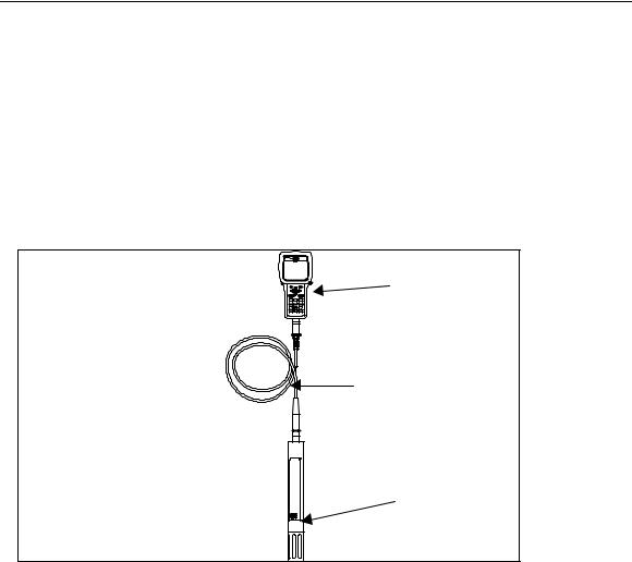
Figure 1. 650 interfaced to a 6-series sonde.
|
|
650 |
You will need: |
|
|
∙ |
650 |
|
∙ |
6-series sonde |
|
|
with integral |
Integral or field cable |
|
cable or YSI |
with sonde connector |
|
field cable |
|
YSI 6-series sonde
YSI Incorporated |
7 |
650 MDS |
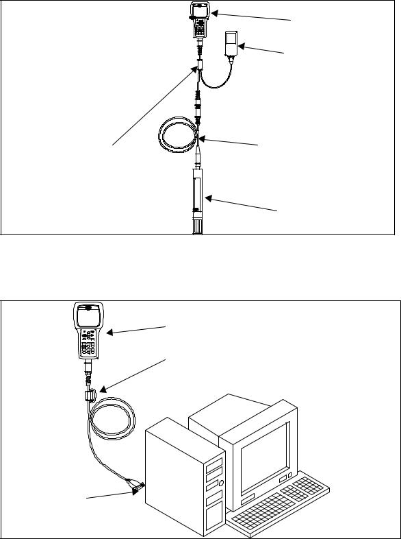
Figure 2. 650 interfaced to a 6-series sonde with user-supplied GPS.
You will need:
∙650
∙6115 GPS cable
∙User-supplied GPS unit with DE-9 cable
∙YSI 6-series sonde with integral or field cable
650
User-supplied GPS unit with DE-9 cable
6115 GPS cable |
Integral or field cable |
YSI 6-series sonde
Figure 3. 650 interfaced to PC for data transfer or software upgrade.
You will need:
650 |
|
|
|
|
∙ |
650 |
|
|
∙ |
YSI 655174 |
|
655174 PC Interface |
|||
|
PC interface |
||
Cable |
|
||
|
cable |
||
|
∙ |
||
|
PC with |
||
|
|||
|
|
active serial |
|
|
|
port |
PC Serial port (DE-9)
YSI Incorporated |
8 |
650 MDS |
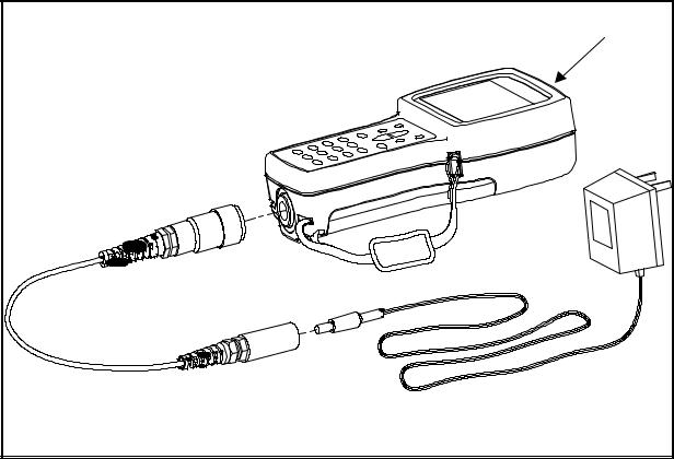
Figure 4. Charging of 650 rechargeable battery pack.
650 |
You will need: |
650 with battery pack installed |
6116 Charger adapter cable |
6114 Wall charger or equivalent |
6116 Charger adapter cable |
6114 wall charger (shown) or 6123 power supply |
The setup of these configurations is described in detail in subsequent sections of this manual. They are presented here so that your will be able to ascertain if you have all of the parts necessary for your applications.
YSI Incorporated |
9 |
650 MDS |
2.4 650 FEATURES
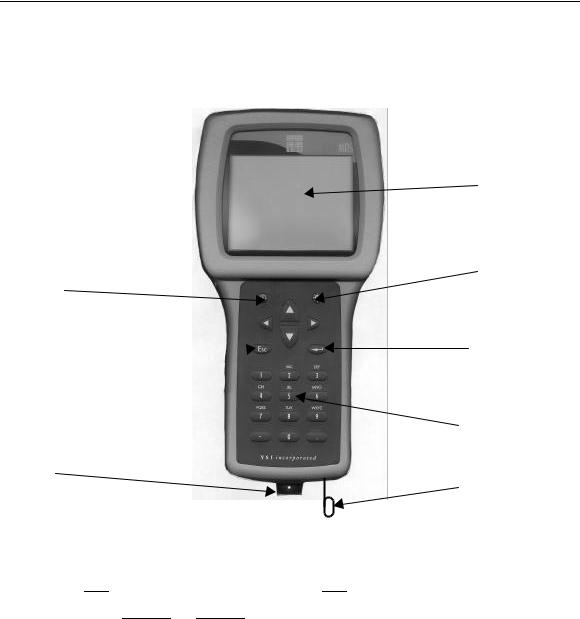
The key physical features of the 650 display and keypad are shown in the figures below.
650 Front View
Display
Backlight Key
On/Off Key
Arrow Keys 
Enter Key
Escape Key 
Cellular Phone-Style Keypad
MS-8 Connector
Strain Relief Lanyard
Note that the YSI 650 keypad consists of 20 keys as shown in the diagram above. There are four function keys, up, down, right and left arrow keys and an alpha/numeric keypad. The top left key that has a green
circle and line,  , is the ON/OFF key. The top right key,
  , activates the display backlight. The
Escape key is labeled  and
and  is the Enter key.
YSI Incorporated |
10 |
650 MDS |
650 Back View
Accessory Connections
Barometer Vent
Patch
Battery Lid
Battery Lid Screws
Note that the back of the case contains the battery lid that is attached to the main case with four captive screws and has three fittings for attachment of the ultraclamp and tripod accessories. In addition, the battery lid has a hole that is covered with water-impermeable patch for venting of the optional barometer.
CAUTION: The barometer-venting patch is resident on the inside of the battery lid. Removal of or damage to this patch will result in water leakage into the battery compartment.
The short cord with loop (lanyard) which is attached to the bottom of the case is attached to the strain relief of the sonde cable. Simply open the D-ring, pass the lanyard loop through the opening, and then close the D-ring.
2.5 BATTERIES AND CHARGING
The YSI 650 can be powered either with 4 alkaline C cells or a rechargeable NiMH battery pack. With the C-cell configuration, the user will be able to power a typical YSI 6-series sonde (active dissolved oxygen and one optical sensor) for approximately 45 hours of continuous operation. The rechargeable battery pack will allow for about 15 hours of continuous use under these conditions. If the sonde is being powered by its own internal batteries, the 650 batteries will last much longer. YSI Sondes with internal battery capability are the 6920, 6600, 600XLM, and 600 OMS.
YSI Incorporated |
11 |
650 MDS |

2.5.1 BATTERY INSTALLATION – C CELLS
Four C cells install easily into the back of the 650. Follow the instructions and diagrams below to install the batteries properly:
∙Using a Phillips or slotted screwdriver, loosen the 4 captive screws on the battery lid and then remove the battery lid completely.
∙Insert the cells between the battery clips, being sure to follow the polarity (+ and -) as indicated on the bottom of the battery compartment.
∙Make certain that the gasket is properly installed on the battery lid before reinstallation.
∙Reinstall battery lid and tighten the 4 captive screws securely and evenly using a Phillips or slotted screwdriver. Do not overtighten.
2.5.2 BATTERY INSTALLATION – RECHARGEABLE BATTERY PACK
The YSI 6113 rechargeable battery pack is self-contained and is easily installed according to the instructions and diagrams below:
Gasket
(4) Screws
∙ Using a Phillips or slotted screwdriver, loosen the 4 captive screws on the battery lid and then remove the battery lid completely.
∙Put the battery lid in a safe place so that it will be available for future use of C cells.
∙Make certain that the gasket is properly installed on the rechargeable battery before installation.
∙Insert the rechargeable battery pack assembly into the battery compartment of the 650.
YSI Incorporated |
12 |
650 MDS |

∙Tighten the 4 captive screws securely and evenly using a Phillips or slotted screwdriver. Do not overtighten
2.5.3 BATTERY CHARGING – RECHARGEABLE BATTERY PACK
The 6117 rechargeable battery pack is charged via the MS-8 connector on the bottom of the instrument and thus the pack must be installed in the 650 for charging. To perform the charging operation, the user will need to locate the proper power supply (6114 for US/Canada/Japan or 6123 with proper power cord for all other countries) and the 6116 charger adapter cable which were supplied with your rechargeable battery pack (6113 for US/Canada/Japan, 6126 for Europe, 6127 for China/Australia). As shown in Figure 4 above, first attach the charger adapter cable to the 650, then insert the barrel connector of the power supply into the barrel of the adapter cable, and finally plug the power supply into an appropriate AC power outlet. The pack can be recharged with the 650 either “on “or “off”. However, if the instrument is “on”, the progress of the charging operation can be viewed in the Status Bar (see Section 2.10 below).
To ensure that you get maximum operational time from the rechargeable battery pack, the user should follow the procedures below:
1.Place your display/logger on charge for approximately 2 hours to obtain an 80-90 % regeneration of battery capacity.
2.Place your display/logger on charge for approximately 6 hours to get a full charge.
3.Do not charge the batteries continuously for more than 48 hours.
4.For long term storage, keep your battery pack between the temperatures of –20 C and 30 C and remove it from the 650 case.
5.Do not charge your batteries at temperatures below 0 C or above 40 C.
6.Do not use or store the battery pack at high temperature, such as in strong direct sunlight, in cars during hot weather, or directly in front of heaters.
If the above steps are not followed, it may result in a decrease in the operational lifetime of your battery pack. In addition, pay particular attention to the method of long term storage of the battery pack as is outlined in the following warning:
CAUTION: If the battery pack/650 will not be used for extended periods of time, the user should remove the battery pack from the instrument. Failure to do this may result in overdischarge of the pack which can have a detrimental effect of its lifetime
Note that YSI provides recharge options for many countries in the selection or the 6116, 6126, and 6127 kits. However, it is possible that the power cord options in these kits will not be correct for some users. In these cases, users should purchase the 6126 or 6127 kit and substitute their local PC type power cord for the power cord shipped with the kit. This power cord is usually readily available at any local electronics store.
An optional automotive cigarette lighter charger (YSI 616) is also available for recharging the 650 battery pack. Note that the user will require the 6116 adapter cable to use the cigarette lighter adapter. Instructions and diagrams for configuring your cigarette lighter charger and changing fuses are shown below and are found on the back of the 616 package. The user should save these instructions when unpacking the accessory and keep them for later reference.
YSI Incorporated |
13 |
650 MDS |
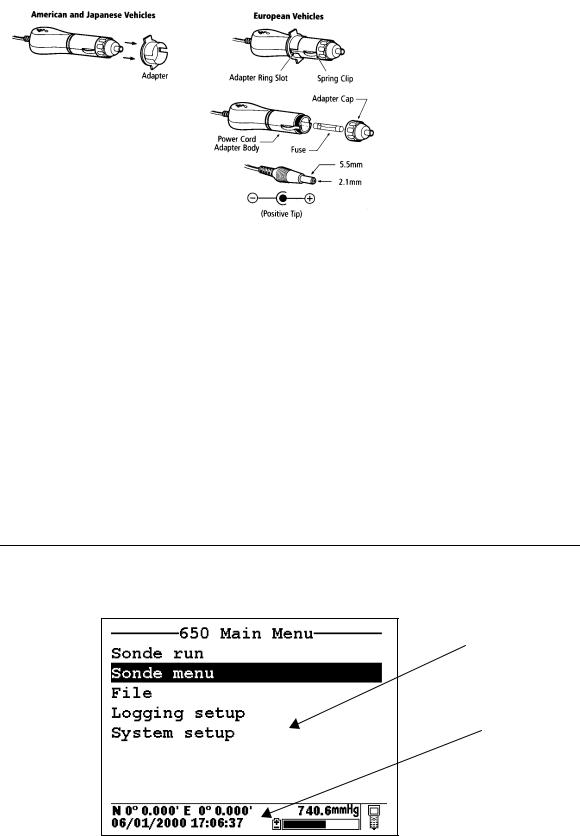
To use the device with an American or Japanese vehicle, slide the adapter ring off of the plug. To use the device with a European vehicle, leave the adapter ring on the plug and position it so the slots on the ring line up with the plug’s spring clips. To begin charging your battery pack, first plug the barrel connector of the cigarette lighter charger into the mating end of the 6116 adapter cable. Then attach the MS-8 end of the 6116 adapter cable to the 650. Finally, plug the other end of the cigarette lighter charger into the vehicle’s lighter socket.
The 616 cigarette lighter charger contains a 2-ampere fast-blow type fuse. If the power cord stops working properly, unscrew the adapter’s cap, remove the tip, and then pull out and check the fuse. See diagram above to remove the fuse. If the fuse is blown or you are unsure, replace it with a new 2-amp fast-blow fuse that is available at electronics stores such as Radio Shack. Reassemble the adapter and securely screw the cap back onto the adapter body.
After you have installed batteries or the rechargeable battery pack into your 650, you are ready to proceed to the next sections.
2.6 TURNING THE INSTRUMENT ON
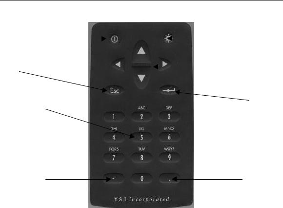
Turn the instrument on by pressing and releasing the on/off button on the top left of the instrument keypad. The following screen should be displayed.
Main Display
Status Bar
YSI Incorporated |
14 |
650 MDS |

Note that the screen is divided into two sections – the “Main Display” at the top and a “Status Bar” at the bottom. The Main Display will provide access to the 650 and sonde menus and will be used to view sonde sensor readings in real-time, to configure the 650 and the sonde, to calibrate the sonde sensors, and to log data to either sonde or 650 memory. The Status Bar will always show the date and time of the 650 clock (updated in real-time), the remaining battery capacity, the current barometer reading if you have purchased this option, the GPS readings from a user-supplied GPS instrument, and will indicate whether the menu being viewed in the Main Display is associated with your sonde or the 650. Additional information about the Status Bar will be provided in Section 2.10 below.
You may also want to take the instrument into a dark room and, with the instrument turned ON, press the backlight key which is located at the top right of the keypad. The instrument backlight should illuminate the LCD so that the display can be read. Pushing the backlight key again will turn the backlight off. The backlight will power off automatically after two minutes of non-use.
2.7 ADJUSTING THE DISPLAY CONTRAST
The contrast of the 650 display is automatically temperature compensated to provide a proper display under most field conditions (-10 to 40 C). Some users, however, may wish to alter the display contrast to meet their own preference. In addition, if the instrument is used at more extreme temperatures, the display is likely to require some adjustment.
The contrast is easily adjusted by pressing and holding down the backlight key in the upper right of the keypad and then pressing repeatedly or holding down the up/down arrow keys while observing the display. Pressing the up arrow while holding down the backlight key increases (darkens) the contrast; pressing the down arrow under these conditions decreases (lightens) the contrast.
NOTE: The backlight itself will only be activated if the backlight key is pressed and released. You must hold down the backlight key to adjust the contrast.
YSI Incorporated |
15 |
650 MDS |
2.8 USING THE YSI 650 KEYPAD
On/Off |
|
|
|
Backlight |
Escape Key |
|
Arrows |
Enter Key
Alpha/Numeric Keys
Minus/Hyphen (-) Key
Period (.) Key
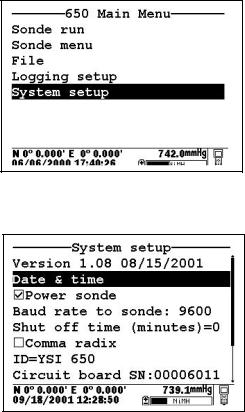
The 650 keypad allows the user to navigate various sonde and 650 menu selections and to make alpha/numeric entries into both the 650 and sonde software. The arrow keys are used to select various options in the menus; the cellular phone-style alpha/numeric keys allow data entry; the Enter key is used to confirm selections; and the Escape key returns the user to the previous position in the menu structure.
The alpha/numeric keys of the 650 can be used to enter both numbers and letters. For many entries, however, where only numbers are appropriate, the software automatically allows ONLY numeric entry, e.g., the letters (ABC) associated with the “2” key cannot be activated. Examples of this type of fixed numeric entry include setting the clock of the 650 or sonde, entering calibration parameters for sonde sensors, and changing entries such as DO warm-up time and optical wiper interval in the Sonde Advanced|Sensor submenu. You will follow an example of this type of entry when you set the 650 clock in the example below.
When both numeric and alpha entry are appropriate for input, the 650 keypad provides a cellular phonestyle interface for choosing the proper character. As shown in the above diagram, the 2-9 keys can also be used to input alpha characters. Basically, to activate a particular alpha/numeric character, the user must press the appropriate key repeatedly until the desired letter or number appears in the display. For example, to enter an M, press the numeric 6 key once and release. To enter an N, press the numeric 6 key twice in rapid succession and then release. Lower case letters are also available for input using this basic method. The following chart shows the alpha/numeric sequence available for each numeric key in the order they will appear as the key is pressed repeatedly.
YSI Incorporated |
16 |
650 MDS |
1 -- 1
2 – ABC2abc2
3 – DEF3def3
4 – GHI4ghi4
5 – JKL5jkl5
6 – MNO6mno6
7 – PQRS7pqrs7
8 – TUV8tuv8
9 – WXYZ9wxyz9
0 -- 0
Using this guide, it can be seen that the character “p” will appear and remain in the display by pressing the 7 key six times in succession. The other characters associated with this key (“P”, “Q”, “R”, “S”, and “7”) will appear during the repeated pressing of the numeric 7 key. However, only the “p” entry will be retained after the key is released after the six keystrokes.
After release of the numeric key for approximately 1second, the cursor will automatically scroll to the right to prepare for the next alphanumeric input. If you make a mistake in the entry, simply return to the previous character with the left arrow key and reenter the number or letter. After the entry is complete, press the Enter key to confirm it. You will follow an example of this type of entry when you enter an Instrument ID name for your 650 in the example below.
To familiarize yourself with the basics of the keypad entry system, follow the instructions below to set the date and time for your 650 and to enter an Instrument ID:
Turn the instrument on to display the 650 Main menu.
Use the arrow keys to highlight the System setup selection and press the Enter key. A display similar to the following will appear (Note that the exact format of your displays will depend on the software version):
YSI Incorporated |
17 |
650 MDS |
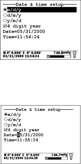
Use the arrow keys to highlight the Date and Time selection and press the Enter key. The following display will appear:
Highlight the selection for your desired date format and press Enter to confirm it.
Highlight the 4-digit year selection and press Enter to toggle between 2-digit (no check mark present) and 4-digit (check mark present) options.
Highlight the Date selection and press Enter. A cursor will appear over the first number in the date as shown in the following display.
Enter the proper number from the keypad for the first date digit. Note that when you release the key, the cursor moves automatically to the next number. Repeat this process until the date is correct. Then press Enter to confirm the Date entry. Note also that, as described above, since alpha characters are inappropriate for this entry, only numeric entry is possible.
Highlight the Time selection and press Enter. Repeat the process described above for the Date to enter your correct local time using the military format. For example, 2:00 PM must be entered as 14:00.
Finally, press the Escape key to return to the System setup menu.
Now highlight the Instrument ID selection and press Enter. The following display will appear.
YSI Incorporated |
18 |
650 MDS |
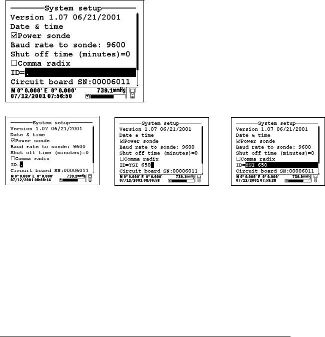
As shown above, enter the designation “YSI 650” using the general instructions outlined above. Start by pressing the numeric 9 key three times in rapid succession while viewing the characters on the display until a “Y” appears. After the entry is complete, pause and the cursor will automatically move to the next entry position. Now press the numeric 7 key four times in succession while viewing the characters on the display. When an “S” appears, pause and the cursor will move automatically to the next entry position. Continue with the entries in this way until ID designation is complete. If you make a mistake, you can use the left arrow key to highlight the flawed entry and correct it. When the entry is complete, press Enter to confirm it. Note that for this example, where both alpha and numeric entries are appropriate, the user must press the numeric 2 key 4 times in succession to generate the number 2, as opposed to the previous clocksetting example where a single press of the numeric 2 key generated the number 2.
After completing the above example, press the Escape key repeatedly to return to the 650 Main menu and then proceed to the next section.
2.9 CONNECTING TO A SONDE
The primary use of the 650 is to interface with YSI 6-series sondes. In this configuration, you will be able to see data from the sonde sensors in real-time on the 650 display as well as to configure the sonde for your particular application. In addition, once sonde interface is established, you will be able to easily log data from the sonde sensors to either the memory of the sonde or the memory of the 650 for later analysis.
The connection between the sonde and the 650 is made via the mating of MS-8 connectors on the standard YSI field cable and the bottom of the 650 case. To make the connection, hold the 650 in one hand, place the 650 and cable connectors together, and rotate the field cable connector until engagement occurs. Then rotate the field cable connector approximately 1-quarter turn until it is fully engaged as evidenced by a
YSI Incorporated |
19 |
650 MDS |
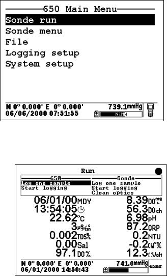
“click”. After connecting the sonde to the 650, press the “on” button on the upper left of the 650 keypad to activate the 650 Main menu as shown below:
Using the arrow keys, highlight the Sonde run entry in the Main 650 Menu and press the Enter key. Readings from the 6-series sonde sensors will appear on the 650 Main Display in real-time as shown in the following diagram.
The two windows at the top of the display give the capability of logging the displayed readings to either the 650 (top left) or the sonde (top right) memory and allow the user to activate the wiper on turbidity and/or chlorophyll probes if they are present in the sonde. Instructions for use of these windows are provided in subsequent sections of this manual. Note also that there is a disk with rotating segments in the upper right corner of the display whose movement confirms that the 650/sonde interface is functional.
To return to the 650 Main menu, press the Escape key.
CAUTION: When using the 650 MDS in field applications which are in close proximity to communication towers and heavy industrial equipment, or which involve very low humidity conditions, the user may experience problems with logger function. If possible, the user should relocate the sampling site away from these potential sources of interference. In most cases, symptoms will involve instrument shutdown or display lockup. These problems can usually be overcome by either simply pressing the on/off key to reactivate the meter display or by resetting the instrument by removal of battery power as described in Section 11 of this manual. If symptoms persist after these actions, consult YSI Customer Service for advice.
YSI Incorporated |
20 |
650 MDS |
2.10 UNDERSTANDING THE STATUS BAR
The diagram below shows the various components of the Status Bar of your 650. Each item identified in the drawing is explained in detail below.
|
|
Main Display |
|
|
Status Bar |
GPS Reading |
|
Barometer Reading |
|
|
|
|
|
Battery Capacity Status |
Date and Time |
|
Menu Indicator |
|
||
|
|
2.10.1Date and Time . This is the date and time for the clock in the 650, set by the user from the System setup menu as described above. The date and time entries are updated in real-time in the Status Bar.
2.10.2GPS Reading. This value will be present only if a user-supplied GPS unit with NMEA 0183 format is connected to the 650 by the optional YSI 6115 cable. The setup of a GPS interface is described in more detail in Section 8 below. Once properly connected to a GPS instrument, the values displayed in the Status Bar are updated in real-time as the system is moved from location to location.
2.10.3Barometer Reading. This value is the current local barometer reading in units selected by the user in the System setup menu. The value is can be used simply as a meteorological parameter or can be used
in calibration of sonde dissolved oxygen sensors. The barometer reading is NOT corrected to sea level and is updated in real-time.
2.10.4 Battery Capacity Status. The graphic indicator shows the portion of the battery capacity that is remaining, either for the 4-C cell configuration or for the optional rechargeable battery pack. If a 6117 rechargeable battery pack is in place, a “NiMH” label will appear as part of the indicator. During charging of the battery pack, the black portion of the icon will pulse horizontally until charging is complete. In addition, the entire battery indicator will flash when your batteries are almost exhausted and require replacement (C-cells) or recharge (optional rechargeable battery pack).
2.10.5 Menu Indicator. This icon is located in the lower right portion of the Status Bar and provides a guide as to whether the menu on the display of the 650 originates in the sonde or the 650 itself. The icon shown in the figure above represents a 650 menu; if the menu on the display had originated in the sonde, the Status bar would display a sonde-like icon as shown below.
YSI Incorporated |
21 |
650 MDS |
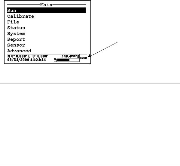
Sonde Icon
2.11 UPGRADING ECOWATCH FOR WINDOWS SOFTWARE
To utilize the full capability of the 650 MDS, you will need to upgrade your version of EcoWatch for Windows from the YSI World Wide Web page (www.ysi.com). Access the YSI Environmental Web Page, select “tech support” from the header, and then “Downloads”. After registration, select the EcoWatch for Windows upgrade entry and follow the instructions provided. After the upgrade is complete, your software version (viewed from the EcoWatch toolbar entry Help|About EcoWatch) should be 3.13.00 or higher.
If you encounter difficulties in the upgrade procedures, contact YSI Customer Service for advice.
After reading the above sections and participating in the simple examples provided, you should be familiar with the basics of battery installation, keypad and display function, and keypad data entry. Please proceed to Section 3 where the setup of your 650 is described in detail.
SECTION 3 SETTING UP THE 650
The 650 has a number of features which are user-selectable or which can be configured to meet the user’s preferences. Most of these choices and selections are found in the System setup selection in the Main 650 Menu. To explore the various setup possibilities of the 650, turn the instrument on, select System setup, and press Enter. The following display will appear. The second display can be observed by scrolling to the bottom of the System setup entries with the down arrow.
YSI Incorporated |
22 |
650 MDS |
Loading...