

York D2CG 072, D7CG 036, D7CG 048, D7CG 060 User Manual

®
SUNLINE 2000
GAS / ELECTRIC
SINGLE PACKAGE AIR CONDITIONERS
INSTALLATION INSTRUCTION
CAUTION
SCROLL COMPRESSORS
OPERATE IN ONLY ONE
DIRECTION.
If the compressor is
experiencing:
- low amperage draw
- similar discharge and
suction pressure
- increased noise level
It is operating in reverse.
Switch two line voltage
connections to correct.
GENERAL
YORK Model DCG units are single package air conditioners
with gas heat desig ned fo r outd oor in st alla tion on a roof top or
a slab.
The units are completely assembled on rigid, permanently
attached base rails. All piping, refrigerant charge, and electrical
wiring is factory-installed and tested. The units require only electric
power, gas piping and duct connections at the point of installation.
The gas-fired heaters have aluminized steel tubular heat
exchangers and spark ignition with intermittent pilot.
This appliance is not to be used for temporary heating of
buildings or structures under construction.
INSPECTION
As soon as a unit is received, it should be inspected for possible
damage during transit. If damage is evident, the extent of the
damage should be noted on the car rier’s freig ht bill. A sepa rate
request for inspec tion by the carr ier’s agent sho uld be made in
writing. Refer to Form 50.15-NM for additional information.
REFERENCE
Additional information on the design, installation, operation and
service of this eq uipment is availa ble in the followi ng reference form s:
55.70-N1 -General Installation
•
55.70-N2 -Pre-start & Post-start Check List
•
530.18-N1.2 V -Economizer Ac ce ss or y
•
530.18-N1.13V -M an. Out door Air Damp er Acc y 0-3 5%
•
530.18-N1.14V -Man. Outdoor Air Damper Accy 0-100%
•
Supersedes: 530. 18 -N 8 Y (2 95)
MODELS D7CG 036, 048 & 060 (10 SEER)
MODEL D2CG 072 (9 EER)
(STYLE A & Belt Drive Option)
Do not store or use gasoline or
other flammable vapors or liquids
in the vicinity of this or any other
appliance
If you smell gas:
1. Open windows
2. Don’t touch electrical switches.
3. Extinguish any open flame.
4. Immediately call your gas supplier.
530.18-N1.12V - Mot oriz ed O utdo or Air Damp er Acc y.
•
530.18-N1.8V -Coil Guard
•
530.18-N2.11V -Low NOx Accessory
•
530.18-N8.2V -High Altitude Accy. (Natural Gas)
•
530.18-N8.3V -High Altit ud e Ac cy. (Propane)
•
530.18-N8.4V -Gas Piping Accessory
•
530.18-N8.12V -Propane Conver sion Accessor
•
690.15-N25V -Low Ambien t Access or y
•
Renewal Parts:
Refer to Part s Manual for comple te listing of repla cement
•
parts on this equipment.
All forms referenced in this instruction may be ordered from:
Publications Distribution Center
Unitary Products Grou p
P.O. Box 1592, York, P A 17405
APPROVALS
Design certified by CGA and UL listed as follows:
1. For use as a forc ed air furnace w ith cooling unit .
2. For outdoor installation only.
3. For installation directly on combustible flooring or, in the U.S.A.,
on wood flooring or Class A, B, or C roof covering material.
4. For use with natural gas and/or propane (LP) gas .
Not suitable for use with conventional venting systems.
530.18-N8Y (1096)
035-14838
FOR YOUR SAFETY
.
Installer should pay particular attention to the words:
the instal lation ea sier . Cautio ns are giv en to prev ent equip ment dam age. W arnings are given to alert installer that personal injury
and/or equipment damage may result if installation procedure is not handled properly.
NOTE, CAUTION
and
WARNING
. Notes are inte nd ed to cl arif y o r make
CAUTION
THIS PRODUCT MUST BE INSTALLED IN STRICT COMPLIANCE WITH THE ENCLOSED INSTALLATION INSTRUCTIONS
AND ANY APPLICABLE LOCAL, STA TE, AND NA TIONAL CODES INCLUDING, BUT NOT LIMITED TO, BUILDING, ELECTRICAL, AND MECHANICAL CODES
WARNING
INCORRECT INSTALLATION MAY CREATE A CONDITION WHERE THE OPERATION OF THE PRODUCT COULD CAUSE
PERSONAL INJURY, PROPER T Y DAM AGE AND/ OR DEATH.
WARNING
DE-ENERGIZE THE ELECTRICAL POWER AND TURN OFF THE GAS SUPPLY TO THE UNIT BEFORE ATTEMPTING TO
INSPECT, REPAIR OR PERFORM MAINT ENANCE TO THE UNIT.

530.18-N8Y
TABLE OF CONTENTS
General................................................................................1
Inspection.............................................................................1
Reference ............................................................................1
Approvals ............................................................................. 1
Nomenclature....................................................................... 2
INSTALLATION
Limitations............................................................................3
Location ...............................................................................3
Rigging and Handling .......................................................... 3
Clearances...........................................................................3
Ductwork .............................................................................. 3
Filters ................................................................................... 4
Condensate Drain................................................................4
Service Access..................................................................... 4
Thermostat.................. ........ ........ ........ ........ ........ ........ ........ .4
Power and Control Wiring.................................................... 4
Blower Speed Selection....................................................... 4
Scroll Compressors....................................................... ....... 4
Combustion Discharge........... .. .. .. .......................... .. ...........4
Disconnect Switch Bracket For Optional Belt-Drive ............ 5
Gas Piping .......................................... .. .............. .............. ... 5
Gas Connection.................. .. .. .. .. .............. .............. .............6
L.P. Units, Tanks and Piping ................................................ 6
Low NOx Application......... ...... ...... ...... ...... ...... ...... ...... .... .....6
Ven t and Comb usti on Air Hood s............. .... .... .... .... .... .... .... .7
Optional Economizer Rain Hood...................................7 & 8
OPERATION
Cooling System.................................................................. 15
Cooling Sequence of Operation......................................... 15
Safety Controls (Cooling)........................... ........................ 15
Heating Sequence of Operation ........................................15
Safety Controls (Heating) ..................................................15
Heat Anticipator Setpoints ................................................. 16
Pre-Start Check List...........................................................16
START-UP
Operating Instructions........................................................ 16
Post-Start Check List (Gas)............................................... 16
Manifold Gas Pre ssur e Adju st ment.................... .... .... .... .. .16
Pilot Checkout.................................................................... 17
Burner Instructions.............................................................17
Burner Air Shutt er Adju stment............ .... ...... ...... ...... ...... ...17
Supply Air Blower and Temperat ure Rise Adjus tment.......17
Checking Gas Input ........................................................... 18
Secure Owner’s Approval.................................................. 18
MAINTENANCE & TROUBLE SHOOTING
Normal Maintenance....... .. .. .. .............. .............. .............. ... 19
Cleaning Flue Passages and Heating Elements............... 19
Troubleshooting .........................................................19 & 20
TABLES
No. Description Page
1 Unit Applicatio n Da ta............ .... .... .... .... .... .. 3
2 Gas Heat Application Data.......................... 4
3 Pipe Sizing .... .................... .................. ....... 5
4 Static Resistances ...................................... 8
5 Physical Data.............................................. 9
6 Supply Air Blower Perf
. 3 - 6 Ton Direct-Drive
7 Motor & Drive Data-Belt-Drive Blower........ 9
8 Supply Air Blower Perf. 3 & 4 Ton Belt-Drive 10
9 Supply Air Blower Perf. 5 & 6 T on Belt-Drive 11
10 Electrical Data Direct- D ri ve.. .. ..................... 12
11 Electrical Data Belt-Drive............................ 12
12 Superheat, 036 ........................................... 12
13 Superheat, 048 ........................................... 13
14 Superheat, 060 ........................................... 13
15 Superheat, 072 ........................................... 13
16 Limit Control Setting ................................... 16
17 Belt Drive Supply Air Mot or Pulle y Adj........ 17
18 Gas Rate - Cubic Feet Per Hour ................ 18
FIGURES
No. Description Page
1 Recommended Drain Piping....................... 4
2 Typical Field Wiring..................................... 5
3 External Supply Connecti on ....................... 6
4 Bottom Supply Connection......................... 6
5 Ven t and Comb usti on Air Hood s......... .... .... 7
6 Economizer Rain Hoo d Assem bly.............. 7
7 Enthalpy Setpoint Adjustment..................... 8
8 Center of Gravity......................................... 9
9 Dimensions and Clearances....................... 14
10 Gas Valve Piping........................... .............. 15
11 Gas Valves.................... .......................... .. .. 16
12 Proper Flame Adjustm ent.................. ...... ... 17
13 Typ ical F lam e Ap pear ance...................... ... 17
14 Belt Adjustment.................... .......... .......... ... 17
15 Press. Drop versus Supply Air CFM........... 18
9
PRODUCT NOMENCLAT URE
D 7 C G 4N
PRODUCT CATEGORY
D = Single Package Air Conditioner
(Air Cooled)
PRODUCT GENERAT ION
2 = 2nd Generation
7 = 7th Generation
PRODUCT IDENTIFIER
CG = Gas/El ectric
2 Unitary Products Group
NOMINAL COOLING
CAPACITY
036 = 3 Ton
048 = 4 Ton
060 = 5 Ton
072 = 6 Ton
0 030 6 2 5
FACTORY INSTALLED
HEAT
N = Gas Heat Installed
VOLTAGE CODE
06 = 208/230-1-60
25 = 208/230-3-60
46 = 460-3-60
58 = 575-3-60
NOMINAL GAS HEATING
OUTPUT CAP ACITY
040 = 40 MBH
060 = 60 MBH
079 = 79 MBH
099 = 99 MBH

INSTALLATION
LIMITATIONS
These units mu st be installe d in accorda nce with the cu rrent
editions of the following national and local safety codes:
In the U.S.A.:
1. National Electrical Co de AN SI /N F PA No . 70 .
2. National Fuel Gas Code Z223.1.
3. Gas-Fired Central Furnace Standard ANSI Z21.47-1993.
4. Local gas utility re quirements.
In Canada:
1. Canadian Electrical Code CSA C22.1
2. Current Gas Installation Codes CAN/CGA-2.3-M93.
3. Local plumbing and was t e water codes.
4. Other applicable local codes.
Refer to Table 1 for Unit Application Data and to T able 2 for Gas
Heat Application Data.
If components are to be added to a unit to meet local codes, they
are to be installed at the dealer’s and / or the customer’s expense.
Size of unit fo r pr op os ed ins tall at io n sh ou ld be base d on hea t
loss / heat gain calculation made according to the methods of
Air Conditioning Contractors of America (ACCA).
TABLE 1
Voltage Variation
Min. / Max.
Supply Air CFM, Nom. 1200 1600 2000 2400
Wet Bulb Temperature (°F) of
Air on Evaporator Coil,
Min. / Max.
Dry Bulb Temperature (°F) of
Air on Condenser Coil,
Min.
1
Utilization range “A” in accordance with ARI St anda rd 110.
2
A low ambient accessory is available for operation down to 0°F.
LOCATION
Use the follow ing guidelines to selec t a suitable location for
these units.
1. Unit i s designed for outdo or installation only.
2. Condenser coils must have an unlimited supply of air.
WARNING:Excessive exposure of this furnace to contami-
3. For ground level installation, a level pad or slab should be
- UNIT APPLICATION DATA
UNIT SIZE 036 048 060 072
208/230V 187 / 253
460V 414 / 504
1
575V 518/630
57 / 72 57 / 72 57 / 72 57 / 72
2
/ Max.
Where a choice of location is possible, p os ition the unit on
either north or east side of building.
nated combustion air may result equipment damage or personal injury. Typical contaminates
include: permanent wave solutions, chlorinated
waxes and cleaners, chlorine based swimming
pool chemicals, water softening chemicals, carbon
tetrachloride, Halogen type refrigerants, cleaning
solvents (e.g. perchloroethylene), printing inks,
paint removers, varnishes, hydrochloric acid, cements and glues, antistatic fabric softeners for
clothes dryers, masonry acid washing materials.
used. The thic kness and size of the pad or sl ab used should
meet local codes and unit weight. Do not tie the slab to the
building foundation.
45 / 120 45 / 120 45 / 120 45 / 120
530.18-N8Y
4. Roof structures must be able to support the weight of the unit
and its options and / or accessories. Unit must be installed on
a solid level roof curb or appropriate angle iron frame.
CAUTION: If a unit i s to be in st al le d o n a roof cu rb or sp ec ia l
frame other than a YORK roof curb, gasketing must
be applied to all su rfaces that come in con tact w ith
the unit underside.
5. Maintain level tolerance to 1/2" maximum across the entire
length or width of the unit.
6. Elevate the unit sufficiently to prevent any blockage of the
air entrances by snow in areas where there will be snow
accumulation. Check the local weather bureau for the
expected snow accumulation in your area.
RIGGING AND HANDLING
Exercise care when moving the unit. Do not remove any
packaging unti l the unit is ne ar the place of installa tion. Rig the
unit by attaching chain or cable slings to the lifting holes
provided in the base rails. Spreaders, whose length exceeds
the largest d imension a cross the un it, MUST be used acr oss
the top of the unit.
BEFORE LIFTING A UNIT, MAKE SURE THAT ITS WEIGHT
IS DISTRIBUTED EQUALLY ON THE CABLES SO THAT IT
WILL LIFT EVENLY.
Units may also be moved or lifted with a forklift. Slotted
openings in the base rails are provided for this purpose.
LENGTH OF FORKS MUST BE A MINIMUM OF 42".
Remove the nesting brackets from the four corners on top of
the unit. All screws that are removed when taking these
brackets off must be replaced on the unit.
CAUTION: An adhesive backed label is provided over the
outside of the co mbu st ion ai r in le t op en in g to prevent moisture from entering the unit whic h could
cause damage to electrical components. Allow this
closure label to remain in place until the combustion air hood i s to be installed (r efer to Figure 5).
Refer to Table 5 for unit weights and to Figure 8 for approximate
center of gravity.
CLEARANCES
All units require certain clearances for proper operation and
service. Installer must make provisions for adequate combustion
and ventilation air in accordance with Section 5.3, Air for
Combustion and Ventilation of the National Fuel Gas Code, ANSI
Z223.1 (in U.S.A.) or Sections 7.2, 7.3 or 7.4 of Gas Installation
Codes CAN/CGA-B149.1 and .2 (in Canada) and/or applicable
provisions of the local building codes. Refer to Figure 9 for the
clearances required for combustible construction, servicing,
and proper unit op er ation.
WARNING: Do not permit overhanging structures or shrubs to
obstruct condenser air discharge outlet, combustion
air inlet or vent outlet.
DUCTWORK
Ductwork should be designed and sized ac cording to the metho ds
in Manual Q of th e Air Conditioning Contrac tors of America (ACCA).
A closed return duct system shall be used. This shall not preclude
use of economizers or outdoor fresh air intake. The supply and
return air duct connections at the unit should be made with flexible
joints to minimize the transmission of noise.
Unitary Products Group 3
530.18-N8Y
The supply and return air duct systems should be designed for the
CFM and static requirements of the job. They should NO T be sized
to match the dimensions of the duct connections on the unit.
CAUTION: When fastening ductwork to the side duct flanges on
the unit, insert the screws through the duct flanges
only . DO NOT insert the screws through the casing.
Outdoor ductwork must be insulated and waterproofed.
Refer to Fig ure 9 for i nformatio n concerni ng side and bo ttom
supply and return air duct openings.
FILTERS
1" filters ar e supp lied with each un it. 2" r eplace ment filt ers m ay
be used wi th no modification to th e filter racks. Filters must
always be installed ahead of the evaporator coil and must be
kept clean or re placed wit h same size and t ype. Dir ty filt ers will
reduce the cap acit y of t he un it an d wi ll re sult in fros ted coil s or
safety shutdown. Minimum filter area and required sizes are
shown in Table 5.
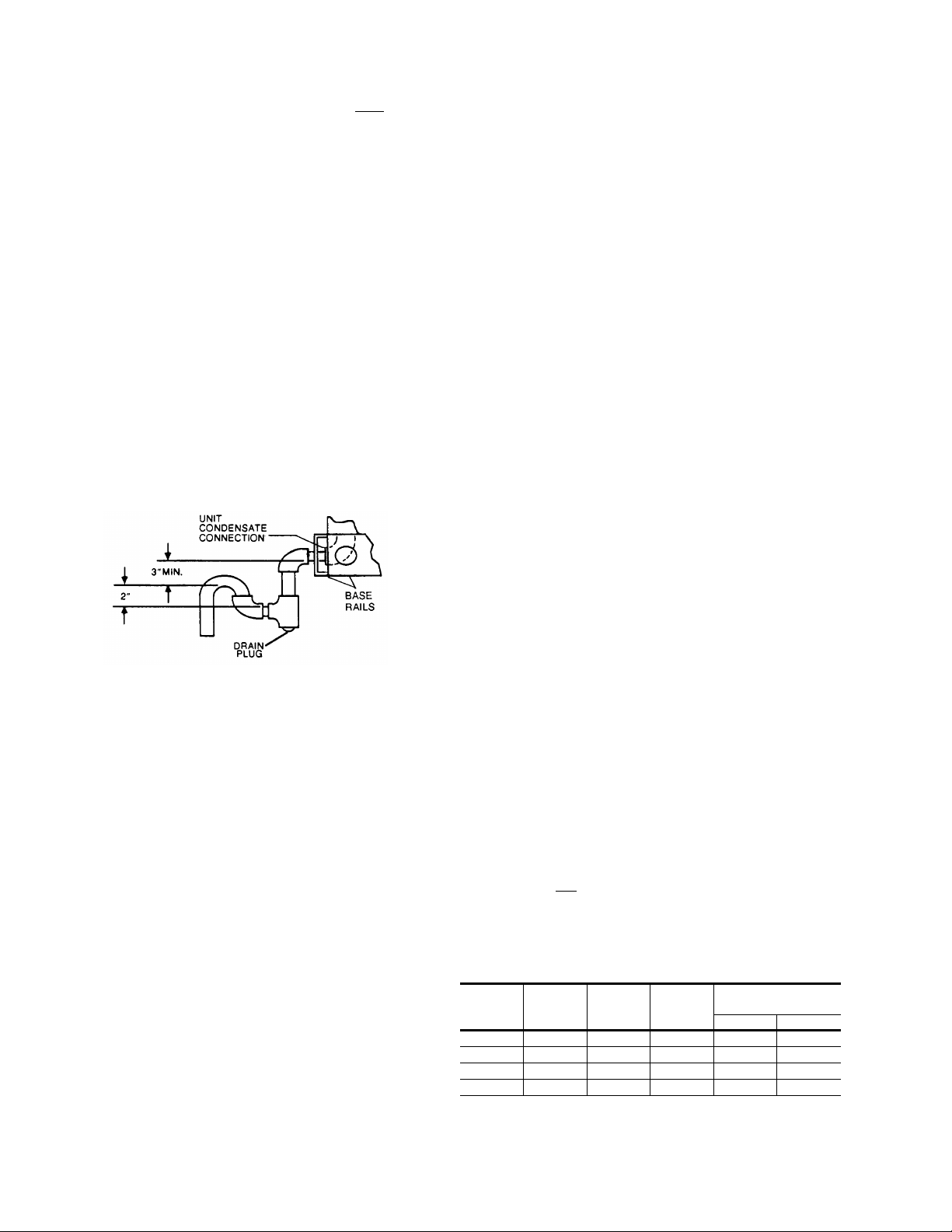
CONDENSATE DRAIN
Plumbing must conform to local codes. Use a sealing compound
on male pipe threads. Install a condensate drain line from the 3/4"
PVC female connection on the unit to spill into an open drain.
NOTE: The condensate drain line MUST be tr apped to provi de
proper drainage. See Figure 1.
POWER AND CONTROL WIRING
Field wiring to the unit must conform to provisions of the National
Electrical Code (NEC), ANSI / NFPA 70-1987 (in U.S.A.) current
Canadian Electric Code (CEC) C22.1 (in Canada), and / or local
ordinances. The unit must be electrically grounded in accordance
with the N.E.C. ANSI / NFP A 70 or local codes.
Voltage tolerances which must be maintained at the
compressor terminals during start-up and running conditions
are indicated on the unit Rating Plate an d Table 1.
The internal wiring harness furnished with this unit is an integral
part of a UL and CGA design certif ied unit. Fi eld altera tion to
comply with electrical codes should not be required.
A disconnect switch shou ld b e fi eld provid ed f or the u nit. The
switch must be separat e from al l other ci rcuits . Refer to Fi gure
9 for installation location. If any of the wire supplied with the
unit must be replaced, replacement wire must be of the type
shown on the wirin g di ag ra m .
Electrical lines must be sized properly to carry the load. USE COPPER
CONDUCTORS ONLY. Each unit must be wired with a separate
branch circuit fed directly from the meter panel and properly protected.
CAUTION: When connecting electrical power and control wir-
ing to the unit, w aterproo f type connecto rs MUST
BE USED so that water or moisture cannot be
drawn into t he unit during nor mal operation. The
above waterproofing conditions will also apply
when installing a field-supplied disconnect switch.
Refer to Figure 2 for typical field wiring and to the appropriate unit
wiring diagram for control circuit and power wiring information.
FIG. 1
- RECOMMENDED DRAIN PIPING
SERVICE ACCESS
Access to all serviceable components is provided by the
following removable panels:
•
Scroll compressor compartment
•
Burner compartment
•
Blower compartment
•
Main control bo x
•
Filter compartment
•
Motor access (on units with belt-drive option)
Refer to Figure 9 for location of these access panels.
CAUTION: Make sure that all scre ws a re re pl ac ed on the unit
to maintain an air-tight seal.
THERMOSTAT
The room thermostat should be located on an inside wall
approximatel y 5 6" ab ove the flo or wh ere it will not be subj ect
to drafts, sun exposure, or heat from electrical fixtures or
appliances. Follow manufacturer’s instructions enclosed with
thermostat for general installation procedure. Color coded
insulated wires (#18 AWG) should be used to connect
thermostat to unit. See Figure 2 for wiring details.
NOTE : If the unit has an economizer, remove jumper J1 from
terminals 8 and 10 on the relay board to prevent simultaneous operation of the scroll compressor and the economizer. If you want to energize the scroll compressor for
supplemental cooling during the economizer operation,
use a thermostat with two stages of cooling.
BLOWER SPEED SELECTION
Three blowe r motor spee ds are ava ilable on the direct- drive
units. The speed selection for the direct-drive units is
determined by the CFM and ESP requirements of the
applications . All units with belt- driv e option have an adjust able
motor pulley to achieve the above conditions.
All direct-drive units with 208/230 voltage are shipped with the
wire labeled # 116 connected to the "HIG H" speed tap on the
blower motor. If a lower blower motor speed is desired, this wire
should be move d to the "MED" or "LOW " speed tap on the
motor for the speed desired.
All direct-drive units with 460 and 575 voltage are shipped with
the wire labeled #116 connected to the "HIGH" speed tap on
the blower motor. If the medium speed is required, connect wire
#116 to the "MED" speed tap and the blue motor lead to the
"HIGH" speed ta p. If the low speed is required, conn ect wire
#1 16 to the "LOW" sp eed tap, the blue mot or lead to the "H IGH"
speed tap and t he orange motor lead to the " M ED" speed tap.
SCROLL COMPRESSOR
These units are shipped with the scroll compressor mountings
factory-adjusted and ready for operation.
CAUTION: Do Not loosen the scroll compressor mounting bolts.
COMBUSTION DISCHARGE
The products of combustion are discharged horizontally
through a screened opening on the gas heat access panel.
TABLE 2
Capacity,
(Mbh)
NOTE: Gas Heaters are shipped available for natural gas, but can be converted to L.P . with Kit Model
No. 1NP0434. All furnaces meet the latest California seasonal efficiency requirements.
1
Based on 1075 Btu/Ft3.
2
The air flow must be adjusted to obtain a temperature rise within the range shown.
- GAS HEA T APPLICA T ION DATA
Input
50 40 3 Ton 47 15 45
75 60 4 Ton 70 25 55
100 79 3/5/6 Ton 93 40/25/25 70/55/55
125 99 4/5/6 Ton 116 45/35/35 75/65/65
Output
Capacity,
(Mbh)
Available
on
Models
Gas Rate
(Ft.3/Hr.)
Temp. Rise °F
1
At Full Input
Min. Max.
2
4 Unitary Products Group

COOLING / HEATING (24 VOLT THERMOSTAT )
THERMOSTAT
TERMINALS
1
UNIT TERMINAL
STRIP TB1
ADD
JUMPER
24 VOLT
TRANSFORMER
TYPICAL CONTROL WIRING
COOLING / HEATING (24 VOL T ELECTRONIC THERMOSTAT)
THERMOSTAT
TERMINALS
ADD
JUMPER
4
ADD
JUMPER
NOT
USED
1
4
UNIT TERMINAL
STRIP TB1
2
3
530.18-N8Y
24 VOLT
TRANSFORMER
1
24 VOLT THERMOSTAT 2TH07701024. IF THE UNIT HAS AN ECONOMIZER,
REMOVE JUMPER J1 FROM TERMINALS 8 AND 10 ON THE RELAY BOARD
TO PREVENT SIMULTANEOUS OPERATION OF THE SCROLL CO MPRESSOR
AND THE ECONOMIZER. IF YOU WANT TO CONTROL THE ECONOMIZER ON A
SECOND STAGE OF COOLING OR HAVE AN ELECTRIC HEAT ACCESSORY
WITH TWO STAGES OF HEAT, USE THERMOSTAT 2TH04701024.
COOLING / HEATING (24 VOL T ELECTRONIC THERMOSTAT)
THERMOSTAT
TERMINALS
1
UNIT TERMINAL
STRIP TB1
ADD
JUMPER
24 VOLT
TRANSFORMER
TYPICAL POWER WIRING
REFER TO ELECTRICAL DATA
TABLES TO SIZE THE DISCONNECT
SWITCH, WIRING & OVERCURRENT
PROTECTION.
TO REMOTE SENSOR
1
ELECTRONIC PROGRAMMABLE THERMOSTAT 2ET04700224 (INCLUDES SUBBASE)
TO CONTROL ECONOMIZER ON SECOND STAGE OF COOLING, REMOVE JUMPER
J1 FROM TERMINALS 8 AND 10 ON THE RELAY BOARD.
2
SECOND STAGE COOLING IS NOT REQUIRED ON UNITS LESS ECONOMIZER.
3
SECOND STAGE HEATING IS ONLY REQUIRED ON UNITS WITH A TWO STAGE
ELECTRIC HEATER.
4
REMOVE JUMPER J2 FROM TERMINALS 4 AND 9 ON JUMPER PLUG CONNECTOR
P6 ON UNITS WITH ECONOMIZER. TERMINALS A1 AND A2 PROVIDE A RELAY
OUT-PUT TO CLOSE THE OUTDOOR ECONOMIZER DAMPERS WHEN THE
THERMOSTA T SWITCHES TO THE SET-BACK POSITION.
1
ELECTRONIC PROGRAMMABLE THERMOSTAT 2ET07701024 (INCLUDES SUBBASE).
IF THIS UNIT HAS AN ECONOMIZER, REMOVE JUMPER J1 FROM TERMINALS 8 AND
10 ON THE RELAY BOARD TO PREVENT SIMUL TANEOUS OPERATION OF THE
SCROLL COMPRESSOR AND THE ECONOMIZER. IF YOU WANT TO CONTROL THE
ECONOMIZER ON A SECOND STAG E OF COOLING, USE THERMOSTAT 2ET04700224.
2TH04702224 IF USED
CAUTION: Label all wires prior t o disconnection when servic-
ing controls. Wiring errors can cause improper and
dangerous op eration. Verify pro pe r operation af te r
servicing.
REFER TO ELECTRICAL DATA
TABLES TO SIZE THE DISCONNECT
SWITCH, WIRING & OVERCURRENT
PROTECTION.
FIG. 2
- TYPICAL FIELD WIRING
DISCONNECT SWITCH BRACKET FOR UNITS
WITH OPTIONAL BELT-DRIVE BLOWER
the current Gas Installatio n Codes CAN/CGA-B149.1 and .2 ( in
Canada) should be followed in all cases unless superseded by
local codes or gas com p an y re qu irements. Refer to Table 3.
A special bracket for mounting a field-supplied disconnect
switch is provided in each unit ordered with an optional
belt-drive supply air blower. The bracket is shipped inside the
blower compartment taped to the top of the blower housing.
Install the bracket on the le ft hand side of the unit as sho w n in
Figure 9. Several existing screws at the top of the unit and one
screw approximately midway down from the top will be used
for mounting t he brack et. Sc rews shou ld be lo osened on ly NOT REMOVED. Matching holes in the bracket have
elongated keyways allowing easy installation. Re-tighten
screws after bracket is in place to ensure panels will remain
leak tight.
GAS PIPING
Proper sizing of gas p ipin g de pend s on the cub ic fee t pe r ho ur
of gas flow required, specific gravity of the gas and the length
of run. “National Fuel Gas Code” Z223-1992 (in the U.S.A.), or
Unitary Products Group 5
TABLE 3
Length in Feet
Maximum capacity of pipe in cubic feet of gas per hour. (Based upon a pressure drop of 0.3
inch water column and 0.6 spe ci fic gr avit y gas) .
- PIPE SIZING
10
20
30
40
50
60
70
80
90
100
Nominal Iron Pipe Size
1/2 in. 3/4 in. 1 in. 1-1/4 in.
132
92
73
63
56
50
46
43
40
38
278
190
152
130
115
105
96
90
84
79
520
350
285
245
215
195
180
170
160
150
1,050
730
590
500
440
400
370
350
320
305

530.18-N8Y
FIG. 3
- EXTERNAL SUPPLY CONNECTION
EXTERNAL SHUT-OFF
FIG. 4
- BOTTOM SUPPLY CONNECTION
EXTERNAL SHUT-OFF
The heating value of the gas may differ with locality. The value
should be checke d w it h th e lo ca l gas utility.
NOTE: There may be a local gas utility requirement specifying
a minimum diameter for gas piping. All units require a
1/2 inch pipe connection at the entrance fitting.
GAS CONNECTION
The gas supply line can be routed through the knockouts
located on the front of the unit or through th e opening pr ovided
in the unit’s base. Refer to Figure 9 to locate these access
openings. Typical supp ly piping arrangements a re shown in
Figures 3 and 4. All shaded items are field-supplied.
Two grommets are shipped in the blower compartment (in parts
bag taped to the blower housing) of every unit with gas heat
and should be used in the knockouts when the gas piping
penetrates the f ro nt of th e un it .
After the gas supply piping has been installed, the bottom
opening shou ld be sealed to prevent water f rom leaking into
the building.
Gas piping recommendations:
1. A drip leg and a ground joint union must be installed in the
gas piping.
2. When required by local codes, a manual shut-off valve may
have to be installed outside of the unit.
3. Use wrought iron or steel pipe for all gas lines. Pipe
compound should be applied sparingly to male threads
only.
WARNING:Natural gas may cont ain some pr op an e. Propane,
4. All piping should b e cleaned of dirt and scale by hamm ering
on the outside of the pipe and blowing out the loose dirt and
scale. Before initial start-up, be sure that all of the gas lines
external to the unit have been purged of air.
5. The gas supply should be a separate line and installed in
accordance with all safety codes as prescribed under
“Limitations”. After the gas connections have been
completed, o pen the main shut -off val ve ad mitting
gas pressu re
soap solution or other material su itable for the purpose.
NEVER USE A FLAME.
being an excellent solvent, will quickly dissolve
white lead or most standard commercial compounds. Therefore, a special pipe compound must
be applied when wrought iron or steel pipe is used.
Shellac base compounds such as Gaskolac or
Stalastic, and compounds such as Rectorseal #5,
Cyde’s or John Crane may be used.
normal
to the mains. Che ck all joint s for leaks wit h
6. The furnace and its individual manual shut-off valve must
be disconnected from the gas supply piping system during
any pressure testing of that system at test pressures in
excess of 1/2 psig (3. 48kPa).
The furnace mu st be isolated from the gas supply piping
system by closing its individual manual shut-off valve during
any pressure t esting of th e gas supply piping syst em at te st
pressures equa l to or le ss tha n 1/ 2 ps ig (3.48kPa).
7. A 1/8 inch NPT plug ged tappin g, acces sible for te st gage
connection, must be installed immediately upstream of the
gas supply connection to the furnace.
L.P./PROP ANE UNITS, TANKS AND PIPING
All gas heat units are shipped from the factory equipped for natural
gas use only. The unit may be converted in the field for use with
L.P./propane gas with accessory kit model number 1NP0440.
All L.P./propane gas equipment must conform to the safety
standards of t he National Fi re Protection Asso ci ation.
For satisfactory operation, L.P ./propane gas pressure must be
10.5 inch W.C at the unit under full load. Maintaining proper gas
pressure depe nds on three main facto rs:
1. The vaporization rate which depends on (a) the
temperature of t he liquid and (b) the “wetted surface” area
of the container or containers.
2. The pr oper pressure regulat ion. (Two-stage regulation is
recommended from the standpoint of both cost and
efficiency.)
3. The pressure drop in the lines between regulators and
between the second stage regulator and the appliance.
Pipe size requi red wi ll depe nd on th e lengt h of th e pipe run
and the total load of all appliances.
Complete information regarding tank sizing for vaporization,
recommended regulator settings, and pipe sizing is available from
most regulator manufacturers and L.P./propane gas suppliers.
L.P./propane gas is an excellent solvent and special pipe
compound must be u se d whe n as se mbl ing pi pi ng for thi s ga s
as it will quickly dissolve white lead or most standard
commercial compounds. Shellac base compounds such as
Rectorseal #5 are satisfactory for this type of gas.
Check all connections for leaks when piping is completed,
using a soap soluti on . NEVER USE A FLAME.
LOW NOx APPLICA TION
For natural gas heat installations in locations which require low
Nitros Oxide emiss ions, accessory model 1LN0 404 must be
installed.
6 Unitary Products Group
 Loading...