

Page 1
YASKAWA 1000-Series Option
24 V Power Supply
Installation Manual
Type: PS-A10LB, PS-A10HB
To properly use the product, read this manual thoroughly and retain
for easy reference, inspection, and maintenance. Ensure the end user
receives this manual.
安川1000シリーズオプション
24 V
制御電源ユニット
取扱説明書
形式:PS-A10LB, PS-A10HB
製品を安全にお使い頂くために,本書を必ずお読みください。
また,本書をお手元に保管していただくとともに,最終的に本製品をご使用になる
ユーザー様のお手元に確実に届けられるよう,お取り計らい願います。
MANUAL NO. TOBP C730600 55D
Page 2

Copyright © 2011 YASKAWA ELECTRIC CORPORATION
All rights reserved. No part of this publication may be reproduced, stored in a retrieval system, or
transmitted, in any form or by any means, mechanical, electronic, photocopying, recording, or otherwise,
without the prior written permission of Yaskawa. No patent liability is assumed with respect to the use of the
information contained herein. Moreover, because Yaskawa is constantly striving to improve its high-quality
products, the information contained in this manual is subject to change without notice. Every precaution has
been taken in the preparation of this manual. Yaskawa assumes no responsibility for errors or omissions.
Neither is any liability assumed for damages resulting from the use of the information contained in this
publication.
2 YASKAWA ELECTRIC TOBP C730600 55D 1000-Series Option PS-A10 Installation Manual
Page 3

Table of Contents
1 PREFACE AND SAFETY . . . . . . . . . . . . . . . . . . . . . . . . . . .4
2 PRODUCT OVERVIEW . . . . . . . . . . . . . . . . . . . . . . . . . . . . 8
3 RECEIVING. . . . . . . . . . . . . . . . . . . . . . . . . . . . . . . . . . . . . . 9
4 OPTION COMPONENTS . . . . . . . . . . . . . . . . . . . . . . . . . .10
5 INSTALLATION AND UNINSTALLATION PROCEDURE . 12
6 VERIFYING OPERATION. . . . . . . . . . . . . . . . . . . . . . . . . .36
7 SPECIFICATIONS . . . . . . . . . . . . . . . . . . . . . . . . . . . . . . .37
YAS KAWA ELE CTR IC TOBP C730600 55D 1000-Series Option PS-A10 Installation Manual 3
Page 4

1 Preface and Safety
1 Preface and Safety
Yaskawa manufactures products used as components in a wide variety of industrial systems
and equipment. The selection and application of Yaskawa products remain the responsibility
of the equipment manufacturer or end user. Yaskawa accepts no responsibility for the way its
products are incorporated into the final system design. Under no circumstances should any
Yaskawa product be incorporated into any product or design as the exclusive or sole safety
control. Without exception, all controls should be designed to detect faults dynamically and
fail safely under all circumstances. All systems or equipment designed to incorporate a
product manufactured by Yaskawa must be supplied to the end user with appropriate
warnings and instructions as to the safe use and operation of that part. Any warnings
provided by Yaskawa must be promptly provided to the end user. Yaskawa offers an express
warranty only as to the quality of its products in conforming to standards and specifications
published in the Yaskawa manual. NO OTHER WARRANTY, EXPRESS OR IMPLIED, IS
OFFERED. Yaskawa assumes no liability for any personal injury, property damage, losses,
or claims arising from misapplication of its products.
◆ Applicable Documentation
The following manuals are available for the option:
Option
YASKAWA 1000-Series Option
24 V Power Supply
Installation Manual
Manual No: TOBP C730600 55
(This book)
4 YASKAWA ELECTRIC TOBP C730600 55D 1000-Series Option PS-A10 Installation Manual
Read this manual first.
The installation manual is packaged with the
option and contains information required to
install the option and set up related unit
parameters.
Page 5

1 Preface and Safety
DANGER
Unit
YASKAWA AC Drive 1000-Series
Quick Start Guide
YASKAWA AC Drive 1000-Series
Technical Manual
YASKAWA D1000 Series
Power Regenerative Converter
Instruction Manual
YASKAWA R1000 Series
Power Regenerative Unit
Instruction Manual
The unit manuals cover basic installation,
wiring, operation procedures, functions,
troubleshooting, and maintenance
information.
The manuals also include important
information about parameter settings and
unit tuning.
Access these sites to obtain Yaskawa
instruction manuals:
U.S.: http://www.yaskawa.com
Europe: http://www.yaskawa.eu.com
Japan: http://www.e-mechatronics.com
Other areas: contact a Yaskawa
representative.
◆ Terms
Note: Indicates supplemental information that is not related to safety messages.
Option: YASKAWA 1000-Series Option 24 V Power Supply
Unit: • YASKAWA D1000 Series Power Regenerative Converter
Drive: YASKAWA 1000-Series Drive
• YASKAWA R1000 Series Power Regenerative Unit
◆ Registered Trademarks
Trademarks are the property of their respective owners.
◆ Supplemental Safety Information
Read and understand this manual before installing, operating, or servicing this option. Install
the option according to this manual and local codes.
The following conventions indicate safety messages in this manual. Failure to heed these
messages could cause fatal injury or damage products and related equipment and systems.
Indicates a hazardous situation, which, if not avoided, will result in death or serious
injury.
YASKAWA ELECTRIC TOBP C730600 55D 1000-Series Option PS-A10 Installation Manual 5
Page 6

1 Preface and Safety
W ARNING
CAUTION
NOTICE
DANGER
Indicates a hazardous situation, which, if not avoided, could result in death or
serious injury.
Indicates a hazardous situation, which, if not avoided, could result in minor or
moderate injury.
Indicates an equipment damage message.
■ General Safety
General Precautions
• The diagrams in this book may include options and units without covers or safety shields to illustrate
details. Be sure to reinstall covers or shields before operating any devices. Use the option according
to the instructions described in this manual.
• Any illustrations, photographs, or examples used in this manual are provided as examples only and
may not apply to all products to which this manual is applicable.
• The products and specifications described in this manual or the content and presentation of the
manual may be changed without notice to improve the product and/or the manual.
• When ordering new copies of the manual, contact a Yaskawa representative or the nearest Yaskawa
sales office and provide the manual number shown on the front cover.
Heed the safety messages in this manual.
Failure to comply will result in death or serious injury.
The operating company is responsible for any injuries or equipment damage resulting
from failure to heed the warnings in this manual.
6 YASKAWA ELECTRIC TOBP C730600 55D 1000-Series Option PS-A10 Installation Manual
Page 7

1 Preface and Safety
NOTICE
WARNING
Read manual before installing.
Wait 5 minutes for capacitor
discharge after disconnecting
power supply.
Risk of electric shock.
AVERTISSEMENT
Lire le manuel avant l'installation.
Attendre 5 minutes après
la coupure de l'alimentation,
pour permettre la décharge
des condensateurs.
Risque de décharge électrique.
危 険
据え付け、運転の前には必ず
取扱説明書を読むこと。
通電中および電源遮断後5分以内は
本体内部,コネクタに触れないこと。
けが.感電のおそれがあります。
WARNING
Read manual before installing.
Wait 5 minutes for capacitor
discharge after disconnecting
power supply.
Risk of electric shock.
危 険
据え付け、運転の前には必ず
取扱説明書を読むこと。
通電中および電源遮断後5分以内は
本体内部,コネクタに触れないこと。
けが.感電のおそれがあります。
WARNING
Read manual before installing.
Wait 5 minutes for capacitor
discharge after disconnecting
power supply.
Risk of electric shock.
Warning
information
Warning
information
Do not modify the unit or option circuitry.
Failure to comply could result in damage to the unit or option and will void warranty.
Yaskawa is not responsible for any modification of the product made by the user. This
product must not be modified.
Do not expose the unit or option to halogen group disinfectants.
Failure to comply may cause damage to the electrical components in the unit or option.
Do not pack the unit in wooden materials that have been fumigated or sterilized.
Do not sterilize the entire package after the product is packed.
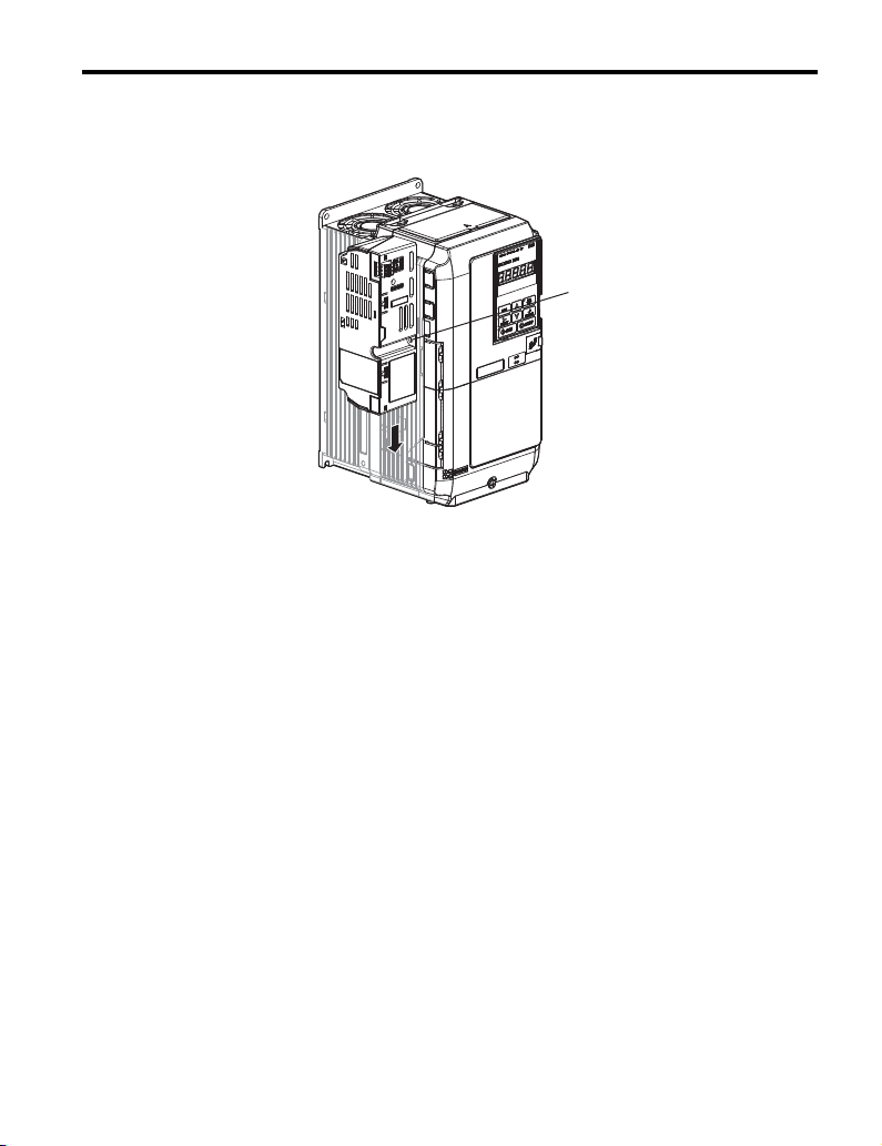
■ Option Label Warnings
Warning information is displayed on the option as shown in the Figure 1. Follow all
warnings and safety instructions when using the product.
When using the unit in an area that may require displaying warning information in Japanese
and English, a warning label is provided with the option. This label can be placed over the
English and French warnings on the front of the option
Figure 1
YASKAWA ELECTRIC TOBP C730600 55D 1000-Series Option PS-A10 Installation Manual 7
Figure 1 Warning Labels
Page 8

2 Product Overview
2 Product Overview
◆ About this Product
The 24 V Power Supply Option maintains unit control circuit power in the event of a main
power outage. As long as the control circuit has power, network communications and I/O
data remain operational. The option provides external power to the control circuit only, and
does not provide power to the main circuit of the unit.
It is possible to read fault and parameter data in the unit via the operator or network
communications when the unit switches to the option as a back-up power supply.
Note: 1. Parameter settings cannot be changed without unit main circuit power regardless of whether the control
◆ Applicable Models
The Option can be used with the unit models in Table 1.
circuit has enough power to operate.
2. When connecting the Option, set the unit Undervoltage Detection Level (Uv) to its default value.
Table 1 Applicable Models
Unit Option Model
CIMR-A2A PS-A10LB
A1000
L1000A
T1000A
Z1000
D1000
R1000
CIMR-A4A
CIMR-A5A
CIMR-L2A PS-A10LB
CIMR-L4A
CIMR-L5A
CIMR-T2A PS-A10LB
CIMR-T4A PS-A10HB
CIMR-Z2A PS-A10LB
CIMR-Z4A PS-A10HB
CIMR-D2A PS-A10LB
CIMR-D4A PS-A10HB
CIMR-R2A PS-A10LB
CIMR-R4A PS-A10HB
PS-A10HB
PS-A10HB
8 YASKAWA ELECTRIC TOBP C730600 55D 1000-Series Option PS-A10 Installation Manual
Page 9

3 Receiving
危 険
据え付け、運転の前には必ず
取扱説明書を読むこと。
通電中および電源遮断後5分以内は
本体内部,コネクタに触れないこと。
けが.感電 のおそれがあります。
WARNING
Read manual before installing.
Wait 5 minutes for capacitor
discharge after disconnecting
power supply.
Risk of electric shock.
MANUAL
3 Receiving
Please perform the following tasks upon receiving the option:
• Inspect the option for damage. Contact the shipper immediately if the option appears
damaged upon receipt.
• Verify receipt of the correct model by checking the model number printed on the option
nameplate. (Refer to Figure 3 on page 11 for more information)
• Contact your supplier if you have received the wrong model or the option does not
function properly.
◆ Option Package Contents
Description: Option
Warning Label <1>
Screws
(M4)
Tapping
Screw
<2>
(M4)
Installation Manual
–
Quantity: 11311
<1> The warning label packaged with the option must be affixed to the option to maintain UL listing. Refer to Option
Label Warnings on page 7 for instructions on label placement.
<2> Only the Z1000 drive requires a tapping screw for installation. For options designed for use with the Z1000 drives,
all packages include tapping screws. Packages including options for other units, however, might or might not
include tapping screws.
◆ Tools Required for Installation
• A Phillips screwdriver (M4 metric / #1, #2 U.S. standard size) is required to install the
option.
• A straight-edge screwdriver (blade depth: 0.4 mm, width: 2.5 mm) is required to install
the unit and wire the option terminal block.
Note: Tools required to prepare option cables for wiring are not listed in this manual.
YASKAWA ELECTRIC TOBP C730600 55D 1000-Series Option PS-A10 Installation Manual 9
Page 10

4 Option Components
4 Option Components
◆ Option
Figure 2
F
E
D
C
G
Side View
A – Connector cable E – Terminal block TB1
B – Connector tabs (6)
C – Model number F – Option cover
D – Charge LED G – Nameplate
Figure 2 24 Vdc Power Supply Option Components
(24 Vdc power supply input)
(Refer to Figure 3 for details.)
A
B
10 YASKAWA ELECTRIC TOBP C730600 55D 1000-Series Option PS-A10 Installation Manual
Page 11

◆ Option Nameplate
55
Figure 3
Option Model Code
Input Specification
Output Specification
Lot Number
Serial Number
Figure 3 PS-A10LB Nameplate Example
◆ Terminal Block TB1
4 Option Components
PS - A10LB
:
MODEL
EUS610031
:
CODE
APPLICABLE INVERTER
: DC24V ± 20% / 1.9A
INPUT
: – ޓޓޓ
OUTPUT
:
O/N
:
S/N
: E131457
FILE NO
Use UL Listed Class 2 power source only.
YASKAWA ELECTRIC CORPORATION
2-1 Kurosaki-shiroishi, Yahatanishi-Ku, Kitakyushu 806-0004 Japan
ޓޓޓ
: A1000 SERIES
MASS
: 0.2kg
PASS
MADE IN JAPAN
IND.CONT.EQ.
7J48
Refer to Table 2 for details on TB1 terminal functions.
■ Terminal Functions
Table 2 Option Terminal Functions
Ter min al Function
24 +24 Vdc Input
00 V
FE Ground
YASKAWA ELECTRIC TOBP C730600 55D 1000-Series Option PS-A10 Installation Manual 11
Page 12

5 Installation and Uninstallation Procedure
W ARNING
5 Installation and Uninstallation Procedure
◆ Section Safety
DANGER
Electric Shock Hazard
Do not connect or disconnect wiring while the power is on.
Failure to comply will result in death or serious injury.
Disconnect all power to the unit and wait at least the amount of time specified on the unit
front cover safety label. After all indicators are off, measure the DC bus voltage to
confirm safe level, and check for unsafe voltages before servicing. The internal capacitor
remains charged after the power supply is turned off.
Electrical Shock Hazard
Do not remove the front covers of the unit while the power is on.
Failure to comply could result in death or serious injury.
The diagrams in this section may include options and units without covers or safety
shields to show details. Be sure to reinstall covers or shields before operating any devices.
Use the option according to the instructions described in this manual.
Do not allow unqualified personnel to use equipment.
Failure to comply could result in death or serious injury.
Maintenance, inspection, and replacement of parts must be performed only by authorized
personnel familiar with installation, adjustment, and maintenance of this product.
Do not touch circuit boards while the power to the unit is on.
Failure to comply could result in death or serious injury.
12 YASKAWA ELECTRIC TOBP C730600 55D 1000-Series Option PS-A10 Installation Manual
Page 13

5 Installation and Uninstallation Procedure
NOTICE
W ARNING
Do not use damaged wires, stress the wiring, or damage the wire insulation.
Failure to comply could result in death or serious injury.
Fire Hazard
Tighten all terminal screws to the specified tightening torque.
Loose electrical connections could result in death or serious injury by fire due to
overheating of electrical connections.
Damage to Equipment
Observe proper electrostatic discharge (ESD) procedures when handling the option,
unit, and circuit boards.
Failure to comply may result in ESD damage to circuitry.
Never shut the power off while the unit is running or outputting voltage.
Failure to comply may cause the application to operate incorrectly or damage the unit.
Do not operate damaged equipment.
Failure to comply may cause further damage to the equipment.
Do not connect or operate any equipment with visible damage or missing parts.
Tighten all terminal screws to the specified tightening torque.
Failure to comply could result in damage to the terminal block.
Do not use unshielded cable for control wiring.
Failure to comply may cause electrical interference resulting in poor system performance.
Use shielded twisted-pair wires and ground the shield to the ground terminal of the unit.
YASKAWA ELECTRIC TOBP C730600 55D 1000-Series Option PS-A10 Installation Manual 13
Page 14

5 Installation and Uninstallation Procedure
NOTICE
Properly connect all pins and connectors.
Failure to comply may prevent proper operation and possibly damage equipment.
Check wiring to ensure that all connections are correct after installing the option
and connecting any other devices.
Failure to comply may result in damage to the option.
◆ Prior to Installing the Option
Prior to installing the option, wire the unit, make the necessary connections to the unit
terminals, and verify that the unit functions normally without the option installed. Refer to
the manual packaged with the unit for information on wiring and connecting the unit.
■ Single Unit Installation
Figure 4 shows the installation distance required to maintain sufficient space for airflow and
wiring.
Figure 4
Top/Bottom Clearance Side Clearance
A
B
B
A
A – 120 mm minimum B – 30 mm minimum
Figure 4 Correct Installation Spacing
Note: IP20/NEMA Type 1 Enclosure and IP00/Open-Chassis models require the same amount of space
above and below the unit for installation.
14 YASKAWA ELECTRIC TOBP C730600 55D 1000-Series Option PS-A10 Installation Manual
Page 15

5 Installation and Uninstallation Procedure
■ Dimensions
The option is 163 mm (6.4 in.) tall and adds 50 mm (2.0 in.) to the width of the unit when
installed.
Figure 5
50 mm (2.0 in.)
163 mm (6.4 in.)
Figure 5 Dimensions
■ UL and CE Compliance
Installation Area
For compliance with UL and CE standards, the option should be placed within the enclosure.
This product must be used in areas with an environment rating no greater than pollution
degree 2 according to UL standards.
Note: 600 V class drives (models CIMR-A5) are not compliant with European
Standards.
External Power Supply
Use a Class 2 power supply as defined by UL standards for the customer-supplied power
supply connection to TB1.
YASKAWA ELECTRIC TOBP C730600 55D 1000-Series Option PS-A10 Installation Manual 15
Page 16

5 Installation and Uninstallation Procedure
◆ Option Installation Methods
There are three different installation methods for the option based on unit model. Find the
unit model number on the unit nameplate and refer to Table 3 to determine the proper option
installation method for your unit.
Table 3 Model-Specific Installation Methods
Unit Model Installation Method Page
CIMR-A2A0004 to 2A0081, 4A0002 to 4A0044, 5A0003 to 5A0032
CIMR-L2A0018 to 2A0075, 4A0009 to 4A0039
CIMR-T2A0004 to 2A0081, 4A0002 to 4A0044
CIMR-Z2A0011 to 2A0114, 4A0005 to 4A0096
CIMR-D2A0005 to 2A0020, 4A0005 to 4A0020
CIMR-R2A03P5 to 2A0028, 4A03P5 to 4A0028
CIMR-A2A0110 to 2A0415, 4A0058 to 4A0414, 5A0041 to 5A0242
CIMR-L2A0085 to 2A0415, 4A0045 to 4A0370, 5A0032 to 5A0200
CIMR-T2A0110 to 2A0415, 4A0058 to 4A0362
CIMR-Z2A0143 to 2A0396, 4A0124 to 4A0361
CIMR-D2A0030 to 2A0130, 4A0030 to 4A0185
CIMR-R2A0035 to 2A0073, 4A0035 to 4A0150
CIMR-A4A0515 to 4A1200
CIMR-L4A0450 and 4A0605
CIMR-Z4A0414 and 4A0590
CIMR-D4A0270 to 4A0630
A 17
B 20
C 24
16 YASKAWA ELECTRIC TOBP C730600 55D 1000-Series Option PS-A10 Installation Manual
Page 17

5 Installation and Uninstallation Procedure
■ Installation Method A
DANGER! Electrical Shock Hazard. Disconnect all power to the unit and wait at least the amount of time
specified on the unit front cover safety label. After all indicators are off, measure the DC bus voltage to
confirm safe level, and check for unsafe voltages before servicing. The internal capacitor remains charged
after the power supply is turned off.
NOTICE: Damage to Equipment. Observe proper electrostatic discharge procedures (ESD) when handling
the option, unit, and circuit boards. Failure to comply may result in ESD damage to circuitry.
1. Shut off power to the unit, wait the appropriate amount of time for voltage to
dissipate, then remove the connector cover by pushing on the connector tab and
Figure 6
Figure 7
sliding the cover towards the top of the unit as indicated by the arrow in Figure 6.
Figure 6 Remove the Connector Cover
2. Pull the loose end of the connection cable out of the option.
Figure 7 Pull Out the Connection Cable
YASKAWA ELECTRIC TOBP C730600 55D 1000-Series Option PS-A10 Installation Manual 17
Page 18

5 Installation and Uninstallation Procedure
Connector tab should face outward
Insertion tabsConnector tabs
3. Firmly plug the end of the connection cable into the CN19 connection port on the
unit.
NOTICE: Make sure the connector is facing in the proper direction when plugging it into the unit. An
improper connection can damage the connector and the unit.
Figure 8
Figure 8 Plug the Connection Cable into the Unit
4. Align the connector tabs on the option with the insertion tabs on the unit as shown in
Figure 9
Figure 9.
Figure 9 Align the Option and the Unit
Note: Take proper precautions when connecting the option so the option will easily fit onto the unit.
Make sure the connector cable is not pinched between the option and the unit.
18 YASKAWA ELECTRIC TOBP C730600 55D 1000-Series Option PS-A10 Installation Manual
Page 19
5 Installation and Uninstallation Procedure
5. Slide the option downward as indicated in Figure 10 to lock it into place on the unit.
For Z1000 drives, use the tapping screw included in the package to attach the
Figure 10
option.
A
A – Use the tapping screw to attach the option
Figure 10 Slide the Option onto the Unit
6. Skip to Option Wiring on page 31.
YASKAWA ELECTRIC TOBP C730600 55D 1000-Series Option PS-A10 Installation Manual 19
Page 20

5 Installation and Uninstallation Procedure
■ Installation Method B
DANGER! Electrical Shock Hazard. Disconnect all power to the unit and wait at least the amount of time
specified on the unit front cover safety label. After all indicators are off, measure the DC bus voltage to
confirm safe level, and check for unsafe voltages before servicing. The internal capacitor remains charged
after the power supply is turned off.
NOTICE: Damage to Equipment. Observe proper electrostatic discharge procedures (ESD) when handling
the option, unit, and circuit boards. Failure to comply may result in ESD damage to circuitry.
1. Shut off power to the unit, wait the appropriate amount of time for voltage to
dissipate, then use a Phillips screwdriver (M4) to remove the screw holding the
Figure11
Figure 12
connector cover in place.
Screw
Connector
cover
Figure 11 Remove the Connector Cover Screw
2. Slide the connector cover as shown in Figure 12.
Figure 12 Slide the Connector Cover
20 YASKAWA ELECTRIC TOBP C730600 55D 1000-Series Option PS-A10 Installation Manual
Page 21

5 Installation and Uninstallation Procedure
3. Insert the blade of a straight-edge screwdriver into the opening shown in Figure 13.
Pull the connector cover in the direction indicated by the arrow and remove it from
Figure 13
Figure 14
the unit.
Figure 13 Remove the Connector Cover
4. Pull the loose end of the connection cable out of the option.
Figure 14 Pull Out the Connection Cable
YASKAWA ELECTRIC TOBP C730600 55D 1000-Series Option PS-A10 Installation Manual 21
Page 22

5 Installation and Uninstallation Procedure
5. Firmly plug the end of the connection cable into the CN19 connection port on the
unit.
NOTICE: Make sure the connector is facing in the proper direction when plugging it into the unit. An
improper connection can damage the connector and the unit.
Figure 15
Option port CN19
Connector cable
Figure 15 Plug in the Connector (CIMR-A2A0110)
6. Align the connector tabs on the option with the insertion tabs on the unit as shown in
Figure 16.
Note: Take proper precautions when connecting the option so the option will easily fit onto the unit.
Figure 16
Make sure the connector cable is not pinched between the option and the unit.
Connector tab
Insertion tab
Figure 16 Tab Locations
22 YASKAWA ELECTRIC TOBP C730600 55D 1000-Series Option PS-A10 Installation Manual
Page 23

5 Installation and Uninstallation Procedure
7. Use a Phillips screwdriver (M4) and the screws included in the option package to
fasten the option to the unit in the three locations shown in Figure 17.
NOTICE: Use only the screws packaged with the option; other screws may damage unit components.
Figure 17
Figure 18
Figure 17 Location of Screws
Figure 18 Option Properly Installed
8. Skip to Option Wiring on page 31.
YASKAWA ELECTRIC TOBP C730600 55D 1000-Series Option PS-A10 Installation Manual 23
Page 24
5 Installation and Uninstallation Procedure
A
■ Installation Method C
DANGER! Electrical Shock Hazard. Disconnect all power to the unit and wait at least the amount of time
specified on the unit front cover safety label. After all indicators are off, measure the DC bus voltage to
confirm safe level, and check for unsafe voltages before servicing. The internal capacitor remains charged
after the power supply is turned off.
NOTICE: Damage to Equipment. Observe proper electrostatic discharge procedures (ESD) when handling
the option, unit, and circuit boards. Failure to comply may result in ESD damage to circuitry.
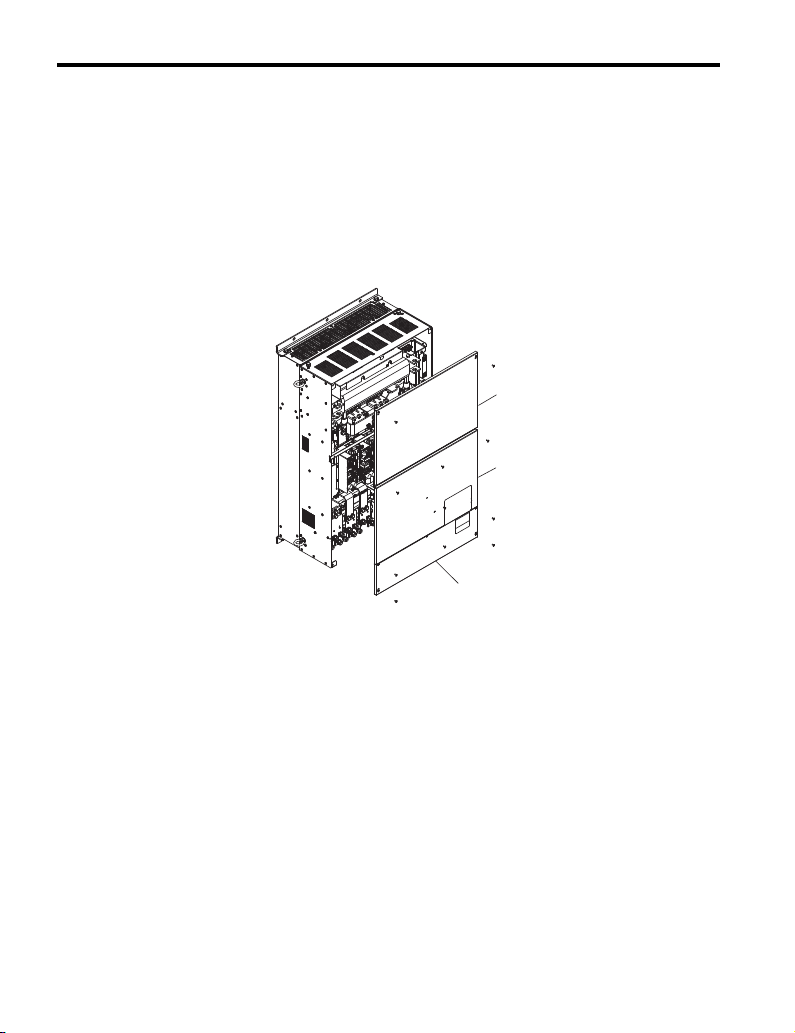
1. Shut off power to the unit, wait the appropriate amount of time for voltage to
Figure 19
dissipate, then use a Phillips screwdriver (M4) to remove the unit covers.
B
C
A – Front cover 1 C – Terminal cover
B – Front cover 2
Figure 19 Remove the Covers
24 YASKAWA ELECTRIC TOBP C730600 55D 1000-Series Option PS-A10 Installation Manual
Page 25

5 Installation and Uninstallation Procedure
A
2. Remove the bracket used to hold the option in place.
Figure 20
A – Bracket for option
Figure 21
Figure 20 Removing the Bracket (CIMR-A4A0515, 4A0675)
A
A – Bracket for option
Figure 21 Removing the Bracket (CIMR-A4A0930, 4A1200)
YASKAWA ELECTRIC TOBP C730600 55D 1000-Series Option PS-A10 Installation Manual 25
Page 26

5 Installation and Uninstallation Procedure
3. Pull the loose end of the connection cable out of the option.
Figure 22
Figure 22 Pull Out the Connection Cable
4. As shown in Figure 23, the cable and connector should pass through the bracket.
Figure 23
Figure 23 Pass the Cable and Connector through the Bracket
26 YASKAWA ELECTRIC TOBP C730600 55D 1000-Series Option PS-A10 Installation Manual
Page 27

5 Installation and Uninstallation Procedure
A
5. Connect the option to the bracket so that the connector tabs on the unit catch and
Figure 24
hold it in place.
A – Connector tabs to catch the bracket
Figure 24 Connecting the Option to the Bracket
YASKAWA ELECTRIC TOBP C730600 55D 1000-Series Option PS-A10 Installation Manual 27
Page 28

5 Installation and Uninstallation Procedure
6. Use a Phillips screwdriver (M4) and the screws included in the option package to
fasten the option to the bracket in the three locations shown in Figure 25.
NOTICE: Use only the screws packaged with the option; other screws may damage unit components.
Figure 25
Figure 25 Securing the Option to the Bracket
7. Firmly plug the end of the connection cable into the CN19 connection port on the
unit.
NOTICE: Make sure the connector is facing in the proper direction when plugging it into the unit. An
improper connection can damage the connector and the unit.
Figure 26
Figure 26 Plugging the Connector
28 YASKAWA ELECTRIC TOBP C730600 55D 1000-Series Option PS-A10 Installation Manual
Page 29

5 Installation and Uninstallation Procedure
A
8. With the option now affixed to the bracket, reinstall the bracket back in its originally
location.
Note: Take proper precautions when connecting the option so the option will easily fit onto the unit.
Figure 27
Figure 28
Make sure the connector cable is not pinched between the option and the unit.
A – Option affixed to the bracket
Figure 27 Installing the Option
Figure 28 Option Properly Installed
YASKAWA ELECTRIC TOBP C730600 55D 1000-Series Option PS-A10 Installation Manual 29
Page 30

5 Installation and Uninstallation Procedure
A
9. Skip to Option Wiring on page 31. After wiring the terminal TB1, reinstall the unit
Figure 29
covers to their original locations.
B
C
A – Front cover 1 C – Terminal cover
B – Front cover 2
Figure 29 Reinstall the Covers to the Unit
30 YASKAWA ELECTRIC TOBP C730600 55D 1000-Series Option PS-A10 Installation Manual
Page 31

5 Installation and Uninstallation Procedure
Preparing wire ends:
Screwdriver blade size
about 5.5 mm (7/32”)
When not using
crimped insulated
sleeves
Pull back the shielding and lightly
twist the end with fingers, keeping
the ends from fraying.
Blade depth of
0.4 mm or less
Blade width of
2.5 mm or less
◆ Option Wiring
1. Select an external power supply.
When the option is first switched on, two times the normal current will flow through
the option for approximately 0.5 seconds. The option requires at least 3 A to
function properly.
WARNING! Electrical Shock Hazard. Use a battery or a double-reinforced UL Class 2 power supply to
provide power to the option. Using a different type of power supply may result in death or serious injury by
electrical shock or fire.
2. Wire the Terminal Block TB1.
Wire the external power supply to terminal block TB1 on the option.
Use a flat-blade screwdriver to loosen the screws on the option plug, connect wiring
to the 24 V, 0, and FE terminals as shown in Figure 30, then tighten the terminal
screws to hold wiring in place.
Refer to Wire Gauges and Tightening Torques on page 32 to confirm that the
proper tightening torque is applied to each terminal. Take particular precaution to
ensure that each wire is properly connected and wire insulation is not accidentally
pinched into electrical terminals.
NOTICE: Be sure to properly connect an external 24 Vdc power source to the power supply plug. Refer to
Option Specifications on page 37 for details. Improper wiring practices could damage the option due to
incorrect terminal connections.
Figure 30
WARNING! Fire Hazard. Tighten terminal screws to the specified tightening torque. Loose electrical
connections could result in death or serious injury by fire due to overheating. Tightening screws beyond the
specified tightening torque may cause erroneous operation, damage the terminal block, or cause a fire.
NOTICE: Heat shrink tubing or electrical tape may be required to ensure that cable shielding does not
contact other wiring. Insufficient insulation may cause a short circuit and damage the option or unit.
YASKAWA ELECTRIC TOBP C730600 55D 1000-Series Option PS-A10 Installation Manual 31
Figure 30 Wire the Option Plug
Page 32
5 Installation and Uninstallation Procedure
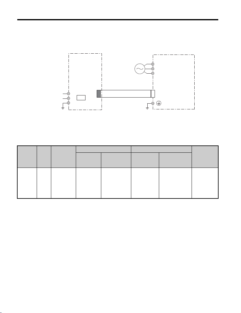
■ Connection Diagram
Figure 31 illustrates the 24 Vdc Power Supply Option and unit connections.
Figure 31
Option
UL Class 2
24 V Power
Supply Input
24 V
+
CN-1
−
FE
TB1
0 V
Figure 31 Connection Diagram for Unit and Option
Note: 24 Vdc external power supply input is supplied by the customer.
■ Wire Gauges and Tightening Torques
Table 4 Wire Gauges and Tightening Torques
Ter min al
Number
Screw
Size
24, 0, FE M2
Tightening
Torque
Nxm
(inxlb)
0.22 to 0.2
(1.95 to 2.21)
Bare Cable Crimp Terminals
Recomm.
Gauges
mm
0.75
(18 AWG)
2
(24 to 17 AWG)
(24 to 16 AWG)
Applicable
Gauges mm
Standard wire:
0.25 to 1.0
Single line:
0.25 to 1.5
2
AC input
Recomm.
Gauges mm
0.5
(20 AWG)
Unit
R/L1
S/L2
T/L3
CN19
Applicable
2
Gauges mm
0.25 to 0.5
(24 to 20 AWG)
2
Wire Type
Shielded
cable, etc.
32 YASKAWA ELECTRIC TOBP C730600 55D 1000-Series Option PS-A10 Installation Manual
Page 33

5 Installation and Uninstallation Procedure
◆ Uninstalling the Option
There are three different Uninstallation methods for the option based on unit model. Find the
unit model number on the unit nameplate and refer to Tab l e 5 to determine the proper option
installation method for your unit.
Table 5 Uninstallation Method
Unit Model Uninstallation Method
CIMR-A2A0004 to 2A0081, 4A0002 to 4A0044, 5A0003 to 5A0032
CIMR-L2A0018 to 2A0075, 4A0009 to 4A0039
CIMR-T2A0004 to 2A0081, 4A0002 to 4A0044
CIMR-Z2A0011 to 2A0114, 4A0005 to 4A0096
CIMR-D2A0005 to 2A0020, 4A0005 to 4A0020
CIMR-R2A03P5 to 2A0028, 4A03P5 to 4A0028
CIMR-A2A0110 to 2A0415,4A0058 to 4A0414, 5A0041 to 5A0242
CIMR-L2A0085 to 2A0415, 4A0045 to 4A0370, 5A0032 to 5A0200
CIMR-T2A0110 to 2A0415, 4A0058 to 4A0362
CIMR-Z2A0143 to 2A0396, 4A0124 to 4A0361
CIMR-D2A0030 to 2A0130, 4A0030 to 4A0185
CIMR-R2A0035 to 2A0073, 4A0035 to 4A0150
CIMR-A4A0515 to 4A1200
CIMR-L4A0450 and 4A0605
CIMR-Z4A0414 and 4A0590
CIMR-D4A0270 and 4A0630
A
B
C
YASKAWA ELECTRIC TOBP C730600 55D 1000-Series Option PS-A10 Installation Manual 33
Page 34

5 Installation and Uninstallation Procedure
■ Uninstallation Method A
Insert the blade of a straight-edge screwdriver as shown in Figure 32, and gently slide the
option in the direction indicated by the arrow.
NOTICE: Do not use excessive force when removing the option. Failure to comply can damage the cable
and the connector.
NOTICE: For Z1000 drives, first remove the screw used to fasten the option into place.
Figure 32
Figure 32 Uninstallation Method A
34 YASKAWA ELECTRIC TOBP C730600 55D 1000-Series Option PS-A10 Installation Manual
Page 35

5 Installation and Uninstallation Procedure
A
■ Uninstallation Method B
Remove the three screws used to fasten the option into place during installation as shown in
Figure 33 to uninstall the option.
Figure 33
Figure 33 Uninstallation Method B
■ Uninstallation Method C
After removing the unit covers, remove the bracket and option as shown in Figure 34.
Figure 34
A – Remove the bracket and option
Figure 34 Uninstallation Method C
YASKAWA ELECTRIC TOBP C730600 55D 1000-Series Option PS-A10 Installation Manual 35
Page 36

6 Verifying Operation
6 Verifying Operation
After properly wiring and installing the option, use the following procedure to check for
normal operation:
1. Make sure the unit main circuit power is on, 24 Vdc external power is supplied to the
24 V connector plug, and the 24 V connector plug is connected to the option.
2. Switch off the main power supply to the unit. The 24 Vdc external power supply
should provide power to the unit control unit.
3. Check for the red LED on the option indicating proper option operation.
4. The digital operator on the unit will display “Uv” for about 10 seconds to indicate an
undervoltage condition on the unit.
If “Uv” does not flash on the display screen, check the wiring. If “Uv” fails to appear
on the digital operator after confirming proper wiring, the unit or option may be
damaged.
◆ Power Supply and the Control Circuit
Table 6 outlines the various conditions under which the option provides power to the control
circuit.
Table 6 Power Supply and Control Circuit
Unit Main Circuit Input
Power Supply
ON ON
ON OFF Possible
OFF ON Not possible
OFF OFF Stop Not possible
Power from Option
Control Circuit
Operation in Unit
Normal operation
Unit Operation
Possible
36 YASKAWA ELECTRIC TOBP C730600 55D 1000-Series Option PS-A10 Installation Manual
Page 37
7 Specifications
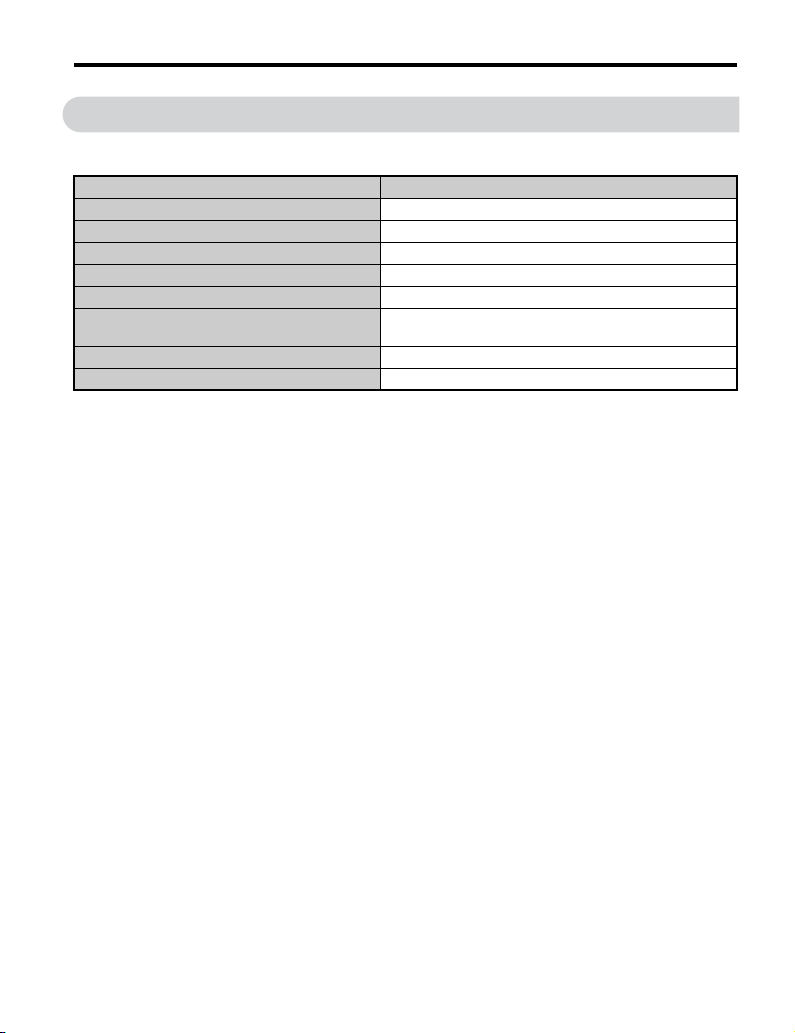
7 Specifications
Table 7 Option Specifications
Item
Input Operating Voltage 24 Vdc ± 20% (19.2 V to 28.8 V)
Input Current 1.9 A
Consumption Power 38 W
Output Ride-Thru time (when power is off) Over 50 ms
Ambient Temperature -10°C to +50°C (+14°F to +122°F) <1>
Storage Temperature
Weight 0.2 kg (0.4 lbs.)
Compliance UL, CE
<1> The option must be installed in an environment compatible with the unit environmental specifications.
-20°C to +60°C (-4°F to +140°F) allowed for short-term
transport of the product
Specifications
YASKAWA ELECTRIC TOBP C730600 55D 1000-Series Option PS-A10 Installation Manual 37
Page 38

7 Specifications
55
4
321
◆ Revision History
Revision dates and manual numbers appear on the bottom of the back cover.
MANUAL NO.ޓTOBP C730600 55A
Published in Japan July 2012 11-3
Date of publication
1
Revision number
Date of original publication
Date of
Publication
February 2014
November 2013
March 2013
July 2012 Back cover Revision: Address
March 2011 −−First Edition
Revision
Number
Section Revised Content
Entire
Documentation
Chapter 4 Revision: Nameplate
Entire
Documentation
Chapter 4 Revision: Nameplate
Back cover Revision: Address
Entire
Documentation
Back cover Revision: Address
Addition: Applicable models
CIMR-A5A0125 to 5A0242,
CIMR-L4A0060 to 4A0605, 5A0032 to
5A0200
Addition: Applicable models
CIMR-R2A03P5 to 2A0073, 4A03P5 to
4A0150
Revision: Reviewed and corrected entire documentation.
Addition: Applicable models
CIMR-D2A0005 to 2A0130, A4A0005 to
4A0630
Revision: Reviewed and corrected entire documentation.
38 YASKAWA ELECTRIC TOBP C730600 55D 1000-Series Option PS-A10 Installation Manual
Page 39

YASKAWA 1000-Series Option
24 V Power Supply
Installation Manual
DRIVE CENTER (INVERTER PLANT)
2-13-1, Nishimiyaichi, Yukuhashi, Fukuoka, 824-8511, Japan
Phone: 81-930-25-3844 Fax: 81-930-25-4369
http://www.yaskawa.co.jp
YASKAWA ELECTRIC CORPORATION
New Pier Takeshiba South Tower, 1-16-1, Kaigan, Minatoku, Tokyo, 105-6891, Japan
Phone: 81-3-5402-4502 Fax: 81-3-5402-4580
http://www.yaskawa.co.jp
YASKAWA AMERICA, INC.
2121 Norman Drive South, Waukegan, IL 60085, U.S.A.
Phone: 1-800-YASKAWA (927-5292) or 1-847-887-7000 Fax: 1-847-887-7310
http://www.yaskawa.com
YASKAWA ELÉTRICO DO BRASIL LTDA.
Avenida Piraporinha 777, Diadema, São Paulo, 09950-000, Brasil
Phone: 55-11-3585-1100
http://www.yaskawa.com.br
YASKAWA EUROPE GmbH
Hauptstrasse 185, 65760 Eschborn, Germany
Phone: 49-6196-569-300 Fax: 49-6196-569-398
http://www.yaskawa.eu.com
YASKAWA ELECTRIC KOREA CORPORATION
9F, Kyobo Securities Bldg., 26-4, Yeouido-dong, Yeongdeungpo-gu, Seoul, 150-737, Korea
Phone: 82-2-784-7844
http://www.yaskawa.co.kr
YASKAWA ELECTRIC (SINGAPORE) PTE. LTD.
151 Lorong Chuan, #04-02A, New Tech Park, 556741, Singapore
Phone: 65-6282-3003
http://www.yaskawa.com.sg
YASKAWA ELECTRIC (CHINA) CO., LTD.
12F, Carlton Bld., No.21 HuangHe Road, HuangPu District, Shanghai 200003, China
Phone: 86-21-5385-2200
http://www.yaskawa.com.cn
YASKAWA ELECTRIC (CHINA) CO., LTD. BEIJING OFFICE
Room 1011, Tower W3 Oriental Plaza, No. 1 East Chang An Ave.,
Dong Cheng District, Beijing, 100738, China
Phone: 86-10-8518-4086
YASKAWA ELECTRIC TAIWAN CORPORATION
9F, 16, Nanking E. Rd., Sec. 3, Taipei, 104, Taiwan
Phone: 886-2-2502-5003
YASKAWA INDIA PRIVATE LIMITED
#17/A Electronics City, Hosur Road Bangalore 560 100 (Karnataka), India
Phone: 91-80-4244-1900
http://www.yaskawaindia.in
Fax: 55-11-3585-1187
Fax: 82-2-784-8495
Fax: 65-6289-3003
Fax: 86-21-5385-3299
Fax: 86-10-8518-4082
Fax: 886-2-2505-1280
Fax: 91-80-4244-1901
YASKAWA ELECTRIC CORPORATION
In the event that the end user of this product is to be the military and said product is to be employed in any weapons systems or the manufacture
thereof, the export will fall under the relevant regulations as stipulated in the Foreign Exchange and Foreign Trade Regulations. Therefore, be sure
to follow all procedures and submit all relevant documentation according to any and all rules, regulations and laws that may apply.
Specifications are subject to change without notice for ongoing product modifications and improvements.
© 2011-2014 YASKAWA ELECTRIC CORPORATION. All rights reserved.
MANUAL NO. TOBP C730600 55D
Published in Japan February 2014 11-3
13-7-11
4 -0
 Loading...