

Page 1

MicroTrac Gateway - Remote I/O
Part No. 46S03196-0010
02/01/01
RD 3196-10
Warranty. Standard products manufactured by the Company are warranted to be free from defects in workmanship and
material for a period of one year from date of shipment and any products which are defective in workmanship or material will
be repaired or replaced, at the Company's option, at no charge to the Buyer. Final determination as to whether a product is
actually defective rests with the Company. The obligation of the Company hereunder shall be limited solely to repair or replace,
at the Company's discretion, products that fall within the foregoing limitations, and shall be conditioned upon receipt by the
Company or written notice of any alleged defects or deficiency promptly after discovery and within the warranty period, and in
the case of components or units purchased by the Company, the obligations of the Company shall not exceed the settlement that
the Company is able to obtain from the supplier thereof. No products shall be returned to the Company without its prior
consent. Products which the Company consents to have returned shall be shipped prepaid f.o.b. the Company's factory. The
Company cannot assume responsibility or accept invoices for unauthorized repairs to its components, even though defective.
The life of the products of the Company depends, to a large extent, upon the usage thereof, and THE COMPANY MAKES NO
WARRANTY AS TO FITNESS OF ITS PRODUCTS FOR THE SPECIFIC APPLICATIONS BY THE BUYER NOR AS
TO PERIOD OF SERVICE UNLESS THE COMPANY SPECIFICALLY AGREES OTHERWISE IN WRITING AFTER
THE PROPOSED USAGE HAS BEEN MADE KNOWN TO IT.
This warranty does not apply to experimental or developmental products for which NO warranty is made or given and Buyer
waives any claim thereto.
THE FOREGOING WARRANTY IS EXCLUSIVE AND IN LIEU OF ALL OTHER WARRANTIES, EXPRESSED OR
IMPLIED, INCLUDING, BUT NOT LIMITED TO, ANY WARRANTY OF MERCHANTABILITY OR OF FITNESS FOR
A PARTICULAR PURPOSE AND BUYER HEREBY WAIVES ANY AND ALL CLAIMS THEREFORE.
Limitation Of Liability. IN NO EVENT SHALL THE COMPANY BE LIABLE FOR LOSS OF PROFIT, INDIRECT,
CONSEQUENTIAL OR INCIDENTAL DAMAGES WHETHER ARISING OUT OF WARRANTY, BREACH OF
CONTRACT OR TORT.
MicroTrac Gateway
to
Allen-Bradley PLC-5
™
and PLC-3
®
For use on MicroTrac®Local Area Network
Page 2

Table of Contents
i
Table of Contents
12/22/94
Page
INTRODUCTION ............................................................................................. 1
HARDWARE ..................................................................................................... 1
JARC Board Setup ........................................................................................ 3
JARC Board Jumper Selections .................................................................... 3
JARC Board DIP Switch .............................................................................. 3
JARC Board LED Operation ........................................................................ 5
SmartMUX™ Board Setup ........................................................................... 6
SmartMUX™ Board Baud Rate / Last State ................................................ 6
SmartMUX™ Board Rack Address ............................................................. 7
SmartMUX™ Board LED Operation ........................................................... 8
Local I/O Racks ............................................................................................. 8
Terminating the Remote I/O Link ................................................................. 9
GENERAL OPERATION .............................................................................. 10
MicroTrac to PLC (LOGO) ........................................................................ 11
PLC to MicroTrac (LOGI) .......................................................................... 12
MicroTrac to PLC (NUMO) ....................................................................... 13
PLC to MicroTrac (NUMI) ......................................................................... 14
PLC
©
Access to Drive Setup Parameters ................................................... 16
PLC Block Trasfer ...................................................................................... 17
PAC Considerations .................................................................................... 20
TROUBESHOOTING – JARC BOARD ..................................................... 22
TROUBLESHOOTING – SmartMUX™ BOARD .................................... 23
TROUBLESHOOTING – A-B PLC-5™ or PLC-3
®
.................................. 23
PCDU TERMINAL OPERATION ............................................................... 24
Block 0 – Gateway Set-Up ......................................................................... 25
Information Block 1 – Digital Read ........................................................... 25
Information Block 2 – Digital Read ........................................................... 25
Information Block 3 – Digital Write ........................................................... 26
Information Block 4 – Digital Write ........................................................... 26
Information Block 5 – PLC Block Read .................................................... 26
Information Block 6 – PLC Block Read .................................................... 27
Information Block 7 – PLC Block Write .................................................... 27
Information Block 8 – PLC Block Write .................................................... 27
Information Block 9 – MicroTrac Logic Input Allocation ......................... 28
Information Block 10 – MicroTrac Logic Output Allocation .................... 28
Information Block 11 – MicroTrac Numeric Input Allocation .................. 28
Information Block 12 – MicroTrac Numeric Output Configuration ......... 29
Page 3

List of Illustrations
Figure
Number Title Page
1 JARC Interface Board ............................................................................... 1
2 SmartMUX Board ....................................................................................... 2
3 Local I/O Interface Board ........................................................................... 9
3a Local I/O Interface "Plug-In" Modules ...................................................... 9
4 PAC Logic Output to PLC ....................................................................... 11
5 PAC Logic Input from PLC ..................................................................... 12
6 PAC Numeric Output to PLC ................................................................... 13
7 PLC to PAC Numeric Input ..................................................................... 14
8 PLC Initialization Hardware and Signal Flow ..........................................15
9 Sample PAC Diagram .............................................................................. 16
10 Sample PLC Ladder Diagram .................................................................. 19
11 Sample PAC Diagram .............................................................................. 20
List of Tables
Table
Number Title Page
1 JARC Jumper Selection .............................................................................. 3
2 JARC Board SW1 DIP Switch, Positions 1-8 ........................................... 4
3 JARC Board SW1 DIP Switch, Positions 9-11 ......................................... 4
4 JARC Board SW1 DIP Switch, Position 12 ............................................... 5
5 JARC Board LED Operation ...................................................................... 5
6 SmartMUX Board Baud Rate Switch ........................................................ 6
7 SmartMUX Board Last I/O Group Switch ................................................ 6
8 SmartMUX Board Last State Switch ......................................................... 7
9 SmartMUX Board Watchdog Switch ........................................................ 7
10 SmartMUX Board Rack Adddress Selection ............................................. 7
11 SmartMUX Board LED Operation ............................................................ 8
12 Troubleshooting the JARC Board ............................................................ 20
13 Troubleshooting the SmartMUX Board ................................................... 21
14 Troubleshooting the PLC ......................................................................... 21
Table of Contents
ii
Table of Contents
12/22/94
Page 4
INTRODUCTION
1
INTRODUCTION
2/17/95
INTRODUCTION
HARDWARE
The Allen-Bradley Programmable Logic Controller (PLC) Remote I/O
Gateway allows any drive on the MicroTrac
®
LAN to communicate with an
Allen-Bradley PLC-5 or PLC-3 through the 1771 I/O Network. Both logic
and numeric information can be transferred.
CAUTION
The gateway must be properly grounded. Use star washers that
will cut into the metal of the gateway box when mounting to
ensure proper earth ground.
The Allen-Bradley PLC gateway is a self-contained unit with one JARC
interface board, one SmartMUX interface board, one eight-point local I/O
interface board, and a power supply. The NEMA 1 enclosure contains the
electronics with internal connections for AC power, digital I/O points, and
external connections for the MicroTrac LAN. The initial setup is factory
configured, but depending on the application, the following electronic boards
may require setup.
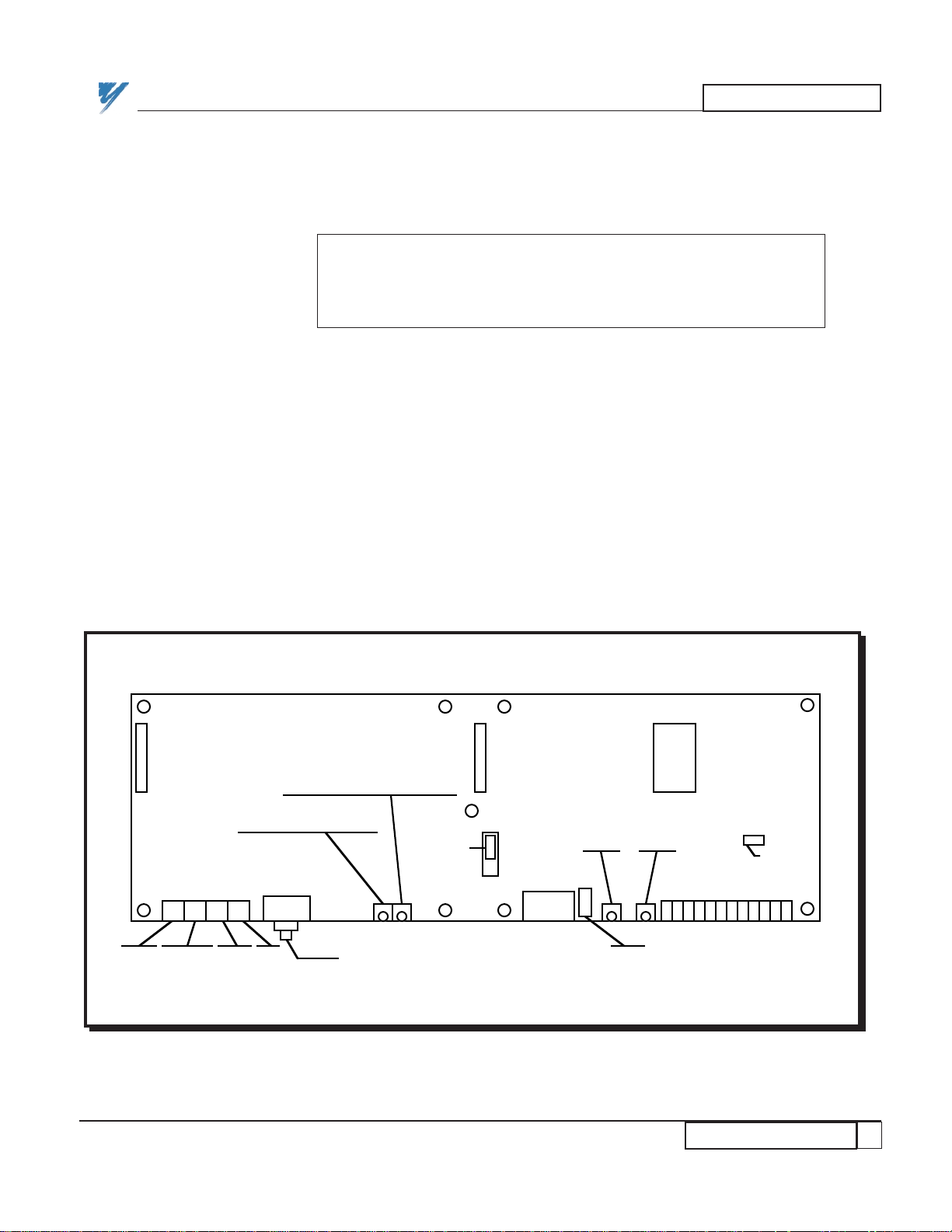
1. The JARC board is the interface board which provides the LAN
connection and communicates with the SmartMUX board through dual port
memory contained on the JARC board. A 12-position DIP switch on the
JARC board, labeled SW1, sets the LAN node address (default = 200) and the
rack address (default = 1). Refer to Figure 1.
Figure 1. JARC Interface Board
J5J6EPROM
J7
+5 V
Ground
–5 VPEJ1
• 128K
• 512K
Jumper
J9
XMIT LED D3 (Red)
RECON LED D4 (Yellow)
J3
PCDU
Connection
Fuse
PGM
LED
SW1
1
12
PWR
LED
F1
LAN
Connection
J8
CTS • • • GRD
Jumper
•
Page 5
HARDWARE
2
HARDWARE
12/22/94- RD 3196-10
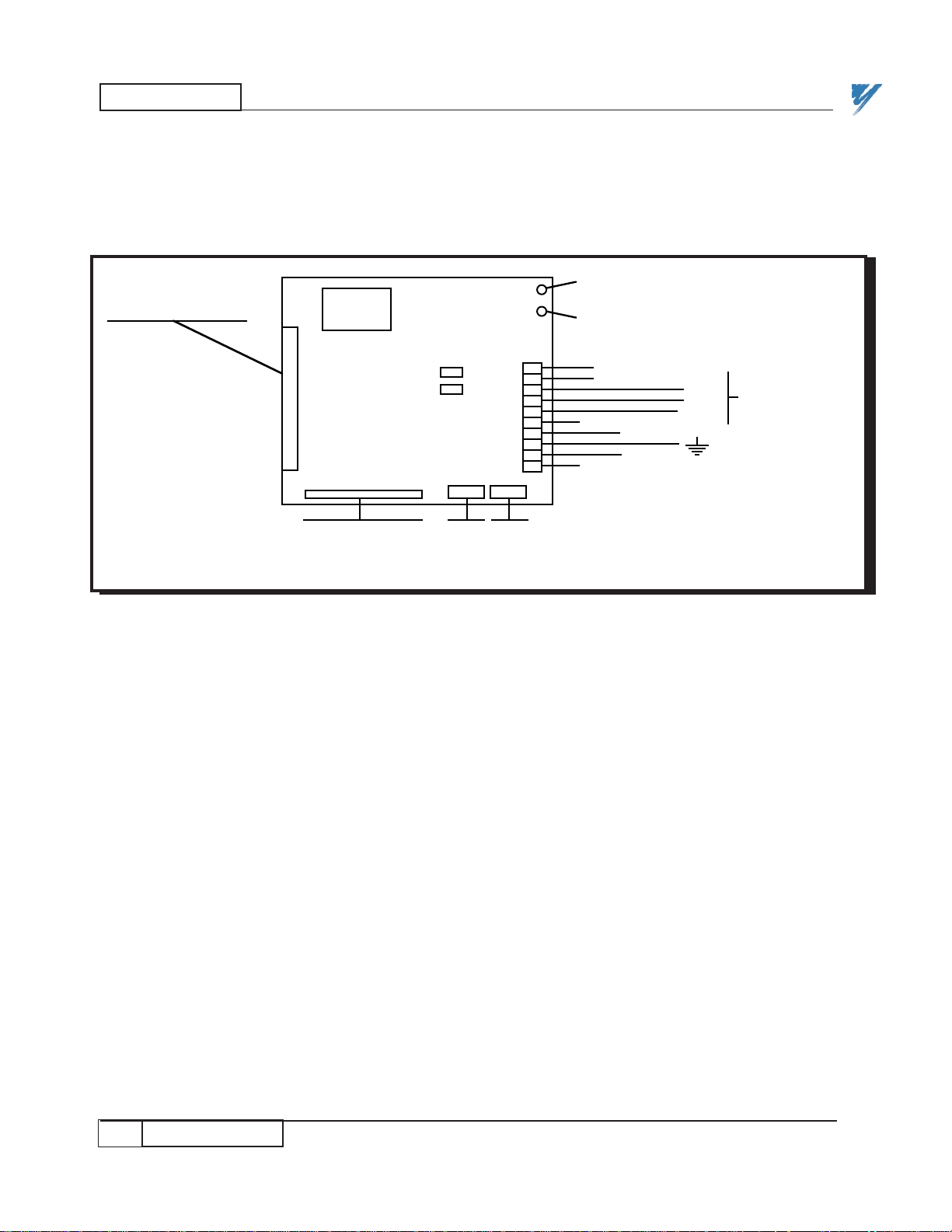
2. One SmartMUX board is attached to the JARC board using screws and a
pluggable 17-pin header. Two 6-position DIP switches on the SmartMUX
board, labeled SW1 and SW2, set the rack address and the baud rate for the
communications. Refer to Figure 2.
Figure 2. SmartMUX Board
J1
EPROM
I/O Rack Connector
J2
PWR LED (Red – for Power)
LED (Green – for Communications)
Connector
to
JARC J5 or JARC J6
SW1
SW2
110RST
ALE
CLR
SHD
BLUE
GND
CCL
CGD
+5V
Connections to
A-B 1771 I/O
Network
Page 6

HARDWARE
3
JARC Board Setup
12/22/94- RD 3196-10
The JARC board has jumpers and one 12-position DIP switch that are user
configurable.
NOTE: The JARC board only reads the DIP switch settings on
power-up.
The proper version of EPROM must be placed in the EPROM socket.
The jumpers located on the JARC board are described in Table 1, with the
defaults shown.
NOTE: On revision "C" and later JARC boards, J1 is an ARCNET
BNC connector and J2 does not exist.
NOTE: If the hand held Portable Command/Display Unit (PCDU)
does not operate properly after plugging into the JARC board J3
RS-232 connector, check the F1 fuse. This fuse protects the +5V
power to the PCDU.
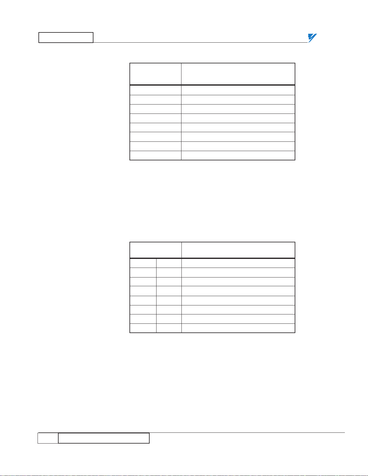
Positions 1 through 8 of DIP switch SW1 determine the LAN node address.
Usually this address is set for 200, when the system has only one PLC gateway.
The address of the second PLC gateway is typically set to 201. Enter the node
ID in binary notation, choosing either a "0" or a"1" for each bit. The least
significant bit is position 1, and the most significant bit is position 8. The
standard gateway addresses are listed in Table 2. The JARC board switches use
pull-down logic, so a closed switch is a logic 0.
JARC Board
Setup
JARC Board
DIP Switch
JARC Board
Jumper
Selections
Table 1. JARC Jumper Selection
JUMPER DEFAULT DESCRIPTION
J8 Center - GND 1-2 CTS (Clear to Send for RS-232)
J9 128K - Center 1-2 RAM_CE2 (Internal selection for
128k static RAM chip)
Page 7
HARDWARE
4
12/22/94- RD 3196-10
JARC Board DIP Switch
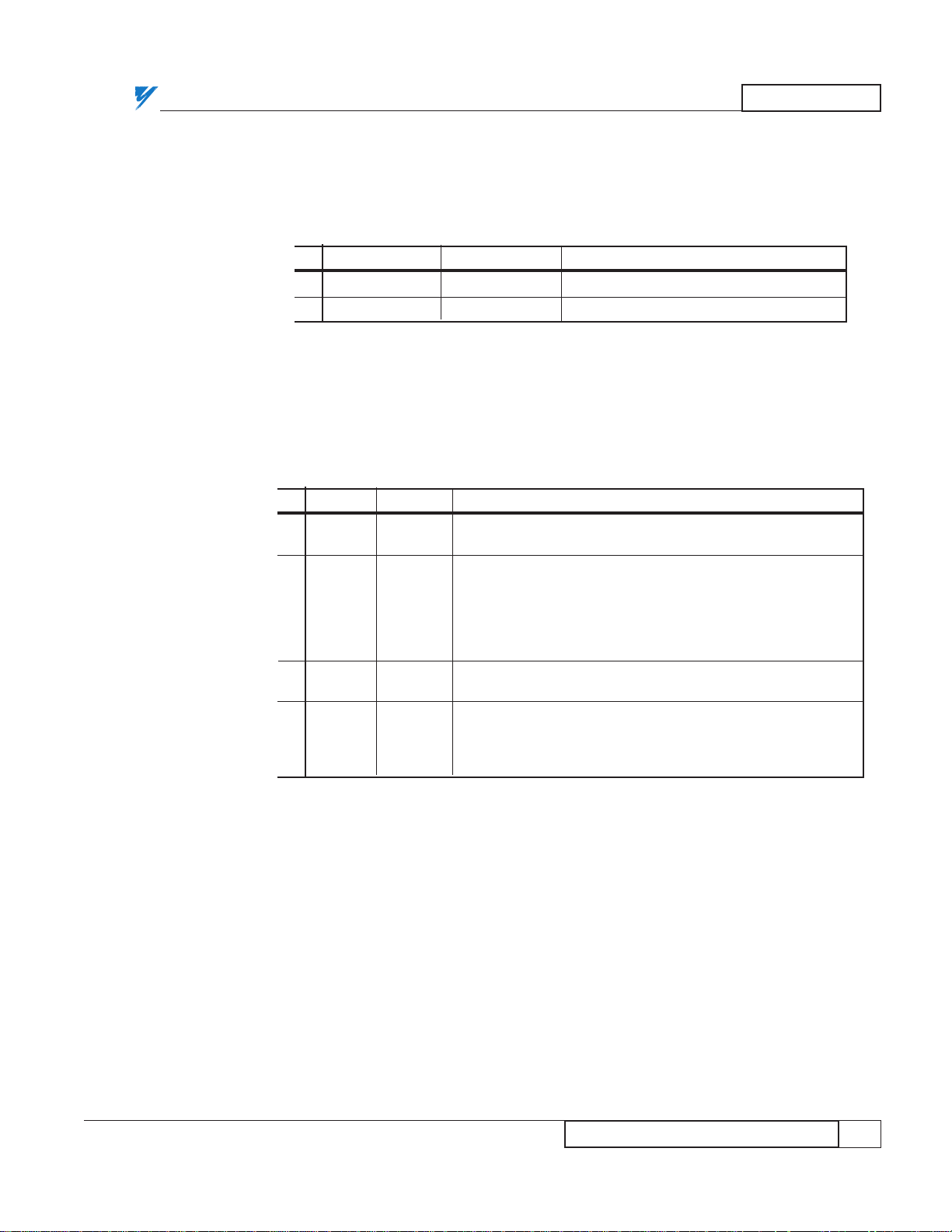
Positions 9, 10, and 11 of DIP switch SW1 determine the starting rack number
for the JARC board to accept on the network (see Table 3). This rack number
must match the lowest rack number selected on the SmartMUX board. The
SmartMUX board is usually wired to JARC board connector J5. Rack 0 is only
valid for a PLC-3.
Table 2. JARC Board SW1 DIP Switch, Positions 1-8
MICROTRAC SW1 DIP Switch Position
LAN
LSB MSB
ADDRESS
1 2 3 4 5 6 7 8
200 X X X O X X O O
201 O X X O X X O O
202 X O X O X X O O
203 O O X O X X O O
204 X X O O X X O O
205 O X O O X X O O
206 X O O O X X O O
207 O O O O X X O O
X = Closed = Logical 0 = Switch ON
O = Open = Logical 1 = Switch OFF
Table 3. JARC Board SW1 DIP Switch, Positions 9 - 11
RACK
SW1 DIP Switch Position
J5 J6 9 10 11
0 1 X X X
1 2 O X X
2 3 X O X
3 4 O O X
4 5 X X O
5 6 O X O
6 7 X O O
7 N/A O O O
X = Closed = Logical 0 = Switch ON
O = Open = Logical 1 = Switch OFF
Page 8
HARDWARE
5
12/22/94- RD 3196-10
JARC Board LED Operation
Position 12 of DIP switch SW1 enables or disables the hardware watchdog (see
Table 4). The hardware watchdog resets the JARC board if a hardware or
software failure occurs. This feature should be enabled for all installations.
There are four LEDs on the JARC interface board; one power LED and three
user indication LEDs. The placement of the LEDs is shown in Figure 1.
Table 4. JARC Board SW1 DIP Switch, Position 12
WATCHDOG Position 12 DESCRIPTION
ON O Enable Watchdog (DEFAULT)
OFF X Disable Watchdog
X = Closed = Logical 0 = Switch ON
O = Open = Logical 1 = Switch OFF
Table 5. JARC Board LED Operation
LED COLOR DESCRIPTION
PWR RED ON when the JARC board has proper +5V power from the
power supply. The power LED should always be ON.
RECON YELLOW ON when a LAN reconfiguration occurs. Each time a node
enters or leaves the network, a reconfiguration occurs. If the
reconfiguration completes and the network is stable, the
RECON LED will turn OFF after about 1-2 seconds. If this
LED is ON constantly or blinks frequently, a network problem
is likely.
XMIT RED ON when the JARC board is communicating on the network.
This LED is normally on all the time.
PGM RED The PGM LED is used to indicate hardware error conditions.
If this LED is ON, turn off the power to the PLC gateway and
then turn the power back on. If this LED remains ON, then a
hardware problem has been detected with the JARC board.
JARC Board
LED Operation
Page 9
HARDWARE
6
SmartMUX Board Setup
12/22/94- RD 3196-10
SmartMUX
Board Setup
SmartMUX
Board Baud
Rate / Last
State
The SmartMUX board resides on top of the JARC board and is screwed in
place. The SmartMUX board requires four screws to attach it to the JARC
board.
There are two jumper positions on the SmartMUX board, labeled J1 and J2.
These jumpers are used for EPROM functions which are not required by this
implementation of the SmartMUX board, so these jumpers are not installed.
The SmartMUX board has two 6-position DIP switches, labeled SW1 and
SW2, to select the rack address and baud rate. The rack address must be
consecutive between zero and seven (inclusive), and must match the rack
address set on the JARC board.
The first DIP switch, SW1, controls the baud rate, last I/O group, last state,
and watchdog (see Tables 6-9), and one bit of the rack address. The "Baud
Rate" and "Last State" should be the only switches that require modification.
Table 6. SmartMUX Board Baud Rate Switch
DIP Switch SW1
BAUD RATE
Position 1 Position 2
57.6K X X
(DEFAULT)
115.2K O X
230.4K X O
230.4K O O
X = Closed switch = Switch ON
O = Open switch = Switch OFF
Table 7. SmartMUX Board Last I/O Group Switch
DIP Switch SW1
LAST I/O GROUP
Position 3
NOT LAST X
LAST O
(DEFAULT)
X = Closed switch = Switch ON
O = Open switch = Switch OFF
Page 10
HARDWARE
7
SmartMUX Board Rack Address
12/22/94- RD 3196-10
SmartMUX
Board Rack
Address
The following DIP switch settings represent the SmartMUX board connected
to the JARC board via the J5 connector.
Table 8. SmartMUX Board Last State Switch
DIP Switch SW1
LAST STATE
Position 4
RESET ALL X
(DEFAULT)
HOLD ALL O
X = Closed switch = Switch ON
O = Open switch = Switch OFF
Table 9. SmartMUX Board Watchdog Switch
DIP Switch SW1
WATCHDOG
Position 5
DISABLE WATCHDOG X
ENABLE WATCHDOG O
(DEFAULT)
X = Closed switch = Switch ON
O = Open switch = Switch OFF
Table 10. SmartMUX Board Rack Address Selection
DIP Switch / Position
RACK ADDRESS
SW1-6 SW2-1 SW2-2 SW2-3 SW2-4 SW2-5 SW2-6
00 X X X X X X X
01 X X X X O X X
(DEFAULT)
02 X X X O X X X
03 X X X O O X X
04 X X O X X X X
05 X X O X O X X
06 X X O O X X X
07 X X O O O X X
X = Closed switch = Switch ON
O = Open switch = Switch OFF
Page 11

8
HARDWARE
SmartMUX Board LED Operation
12/22/94- RD 3196-10
SmartMUX
Board LED
Operation
There are two LEDs on the SmartMUX board; one status LED and one
communications LED. The function of these LEDs is listed in Table 11.
The placement of the LEDs is shown in Figure 2.
The PLC gateway has local I/O connection points. The SmartMUX board connects
to a local I/O interface board which has 8 logic inputs or logic outputs that can be
either AC or DC. The local interface I/O are always assigned to module group 0,
slot 1 of the rack being simulated by the SmartMUX board. These I/O can be
accessed by the PLC directly, but not by devices on the drive network.
The addresses of the 8 I/O points range from: I:XX0/10 to I:XX0/17 for inputs,
and O:XX0/10 to O:XX0/17 for outputs, where XX is the Gateway rack number
(octal). These I/O must be all inputs or all outputs.
Table 11. SmartMUX Board LED Operation
LED COLOR DESCRIPTION
STATUS RED When the SmartMUX board has proper +5V power from the
(PWR) power supply, this LED will flash once or twice and then turn
OFF. If the LED flashes once, then this node is an odd rack
address. If the LED flashes twice, then this node is an even
rack address.
COMM GREEN When the Allen-Bradley PLC establishes communications with
(LED1) the SmartMUX board, this LED will flash or be ON. A flashing
LED means the PLC is in program mode. A solid or ON LED
means the PLC is in run mode and information is being
transferred. Proper operation with the PLC in run mode
results in this LED being ON.
Local I/O Racks
Page 12

HARDWARE
9
Terminating the Remote I/O Link
12/22/94- RD 3196-10
MagneTek Part Description
Number
05P00090-0327 AC Output Module
05P00090-0328 AC/DC Input Module
05P00090-0329 DC Output Module
05P00090-0330 DC Input Module
05P00090-0331 SPST Relay Output Module
The SmartMUX board is an Allen-Bradley Pyramid Solution product.
Therefore, it must meet Allen-Bradley wiring and communication
specifications. Terminating the remote I/O link is part of the specification the
SmartMUX board must meet. A user must place a terminating resistor on both
physical ends of a remote I/O link to ensure proper operation.
NOTE: Refer to Allen Bradley’s 1785 PLC-5 Family Programmable
Controllers, Hardware Installation Manual, Publication 1785-6.6.6
June 1993 or later, page 7-10 for proper terminating resistor
installation instructions.
Figure 3. Local I/O Interface Board
Figure 3a. Local I/O Interface "Plug-In" Modules
8 LEDs (0 - 7)
+ –
1A Fuse
0123456
7
1
16
Fuse
5A
Spare
5A Fuse
Terminals
Terminals
for power
Input or Output (AC or DC) modules
SmartMUX
Edge
Connector
Terminating the
Remote I/O Link
Page 13

GENERAL OPERATION
10
GENERAL OPERATION
2/17/95- RD 3196-10
GENERAL
OPERATION
The PLC gateway is normally mounted and wired on a Yaskawa drive panel.
The gateway, however, can be mounted remotely by the customer. In this case,
special consideration must be given to the 120 VAC power source for the
gateway power supply. DO NOT connect the gateway power cord directly into
a wall outlet. Instead, use an isolation transformer and tie one side of the
secondary to the nearest earth ground (the steel structure of the building is
usually a good choice). The ground studs on the MicroTrac drive panels or
cabinets must also be connected directly to a solid earth ground in order to
assure that the gateway enclosure and the drive panels are at the same potential.
Improper grounding may cause erratic operation of the LAN.
The PLC gateway, when connected to the A-B 1771 remote I/O cable, is treated
as a remote I/O rack by the PLC. From a PLC-5 the selected rack number can
be between 1 and 7 (inclusive). From a PLC-3 the rack number can be between
0 and 7. Note that the PLC gateway is configured as a rack on the remote I/O
link, and cannot be the same rack number as any other rack on the remote I/O
link. If local racks are to be used, the rack number assigned to the PLC
gateway must be greater than the last local rack number.
The baud rate of the A-B 1771 remote I/O link is determined by the PLC. A
DIP switch on the SmartMUX board selects the A-B 1771 link speed. The
acceptable baud rates are 57.6K, 115.2K, and 230.4K.
A gateway uses one entire remote rack with the following capacity:
— 64 numerics PLC to MicroTrac in group 0, slot 0.
— 64 numerics MicroTrac to PLC in group 0, slot 0.
— 8 local logics (8 inputs or 8 outputs) in group 0, slot 1.
— 112 logics PLC to MicroTrac in groups 1-7.
— 112 logics MicroTrac to PLC in groups 1-7.
CAUTION
The gateway must be properly grounded. When mounting, use star washers
that will cut into the metal of the gateway box to ensure proper earth ground.
.
Page 14

GENERAL OPERATION
11
MicroTrac to PLC
12/22/94- RD 3196-10
MicroTrac to
PLC (LOGO)
Logic outputs from a PAC schematic to a PLC can be visualized as shown in
Figure 4. Logic output (LOGO) PAC blocks send a logic value from the drive
to the remote device specified by the node, channel, and sub channel defined
for that block. The node number for a single PLC gateway is typically 200.
These logics utilize groups 1-7 for a maximum total of 112 (7 x 16) MicroTrac
to PLC logic bits.
The LAN channel number is in octal notation and corresponds directly with
the A-B PLC rack and group number for the associated simulated A-B input.
In addition, the number will have a 100's prefix digit of 1 that can be
associated with the A-B PLC input "I" notation. Thus:
LAN CHANNEL 124 = INPUT RACK 2, GROUP 4 or I:24
LAN CHANNEL 127 = INPUT RACK 2, GROUP 7 or I:27
The sub channel number will also be in octal, and will directly correspond to
the bit number of the simulated output. Thus, the 16 possible bits are:
LAN SUB CHANNEL 00 = BIT 00
: : :
LAN SUB CHANNEL 07 = BIT 07
LAN SUB CHANNEL 10 = BIT 10
: : :
LAN SUB CHANNEL 17 = BIT 17
Each PLC logic input bit can be addressed by no more than one drive. If more
than one drive attempts to initialize the same bit (sub channel) in a given
group, a “Logic Output Allocation Error” message will be sent to the drive
over the LAN.
NOTE: LAN traffic throughput may significantly improved if all logic
values for a particular drive are grouped together and not needlessly
divided between multiple PLC groups.
Figure 4. PAC Logic Output to PLC
TYPICAL LOGO
103-D
LOGO
Node Chan. Sub
200 136 3
LAN Cable
Logic Bits
PLC Gateway
Remote
I/O Cable
PLC Ladder
Logic
I:36/03
Page 15

GENERAL OPERATION
12
PLC to MicroTrac
12/22/94- RD 3196-10
PLC to
MicroTrac
(LOGI)
Logic inputs to a PAC schematic from a PLC can be visualized as shown in
Figure 5. Logic input (LOGI) PAC blocks receive a logic value sent to the
drive from the remote device specified by the node, channel, and sub channel
defined for that block. The node number for a single PLC gateway is typically
200. These logics utilize groups 1-7 for a maximum of 112 (7 x 16) PLC to
MicroTrac logic bits.
The channel number is in octal notation. The first digit is a 0, and can be
associated with the A-B PLC output "O" notation. The 2nd and 3rd digits
represent the rack number and the group number. Thus:
LAN CHANNEL 015 = OUTPUT RACK 1, GROUP 5 or O:15
The sub channel number will also be in octal, and will directly correspond to
the bit number of the simulated input. Thus, the 16 possible bits are:
LAN SUB CHANNEL 00 = BIT 00
: : :
LAN SUB CHANNEL 07 = BIT 07
LAN SUB CHANNEL 10 = BIT 10
: : :
LAN SUB CHANNEL 17 = BIT 17
Any drive can request logic inputs from any rack and group of the PLC that
has outputs defined for that location. The Drive Kernel software will select the
appropriate bit and send it to the appropriate LOGI block.
NOTE: LAN traffic throughput may significantly improved if all logic
values for a particular drive are grouped together and not needlessly
divided between multiple PLC groups.
Figure 5. PAC Logic Input from PLC
TYPICAL LOGI
101-D
LOGI
Node Chan. Sub
200 015 2
LAN Cable
Logic Bit
PLC Gateway
Remote
I/O Cable
PLC Ladder
Logic
O:015/02
Page 16

GENERAL OPERATION
13
MicroTrac to PLC
5/2/95- RD 3196-10
MicroTrac to
PLC (NUMO)
Numeric outputs from a PAC schematic to a PLC can be visualized as shown in
Figure 6. Numeric output (NUMO) PAC blocks send a numeric value from the
drive to the remote device specified by the node, channel, and sub channel defined
for that block. The node number for a single PLC gateway is typically 200.
The channel number here has a similar meaning to that discussed above for the
logic function, except that the leading digit must be a 1. The SmartMUX board
only supports Numeric block transfers to slot 0 and group 0. Thus:
LAN CHANNEL 130 = RACK 3, GROUP 0
The PAC block’s sub channel number will be in decimal, and will normally range
from 0 through 63. This number represents the location of the numeric output data
in the Block Transfer Read data file. Up to 64 values may be processed in one
Block Transfer operation.
Every numeric value exchanged between the drive system and the PLC must have
a unique value for channel and subchannel.
Figure 6. PAC Numeric Output to PLC
TYPICAL NUMO
104-D
NUMO
Node Chan. Sub.
200 110 19
LAN Cable
DATA
PLC Gateway
Remote
I/O Cable
PLC Ladder
Logic
FF
Block
Transfer
Read
Page 17

GENERAL OPERATION
14
PLC to MicroTrac
12/22/94- RD 3196-10
PLC to
MicroTrac
(NUMI)
Numeric inputs to a PAC schematic from a PLC can be visualized as shown in
Figure 7. Numeric input (NUMI) PAC blocks receive a numeric value sent to
the drive from the remote device specified by the node, channel, and sub
channel defined for that block. The node number for a single PLC gateway is
typically 200.
The channel number here has the same meaning as the numeric outputs, except
that the leading digit is always 0. The SmartMUX board only supports
Numeric block transfers to slot 0 and group 0. Thus:
LAN CHANNEL 030 = RACK 3, GROUP 0
The PAC block’s sub channel number will be in decimal, and will normally be
between 0 and 63. This number represents the location of the numeric input
data in the Block Transfer Write data file. Up to 64 values may be processed
in one Block Transfer operation. Only one BTW can be used for each
Gateway.
Figure 7. PLC to PAC Numeric Input
TYPICAL NUMI
102-D
NUMI
Node Chan. Sub.
200 010 39
LAN Cable
DATA
PLC Gateway
Remote
I/O Cable
PLC Ladder
Logic
FF
Block
Transfer
Write
Page 18

GENERAL OPERATION
15
PLC Access to Drive Setup Parameters
12/22/94- RD 3196-10
PLC Access to
Drive Setup
Parameters
The PLC can be used to change the value of drive setup parameters. In the
example illustrated in Figures 8 & 9, the PLC can modify a parameter called
“Master Line Speed”. This parameter is also accessible from the Standard
Control Display Unit (SCDU), the Portable Control Display Unit (PCDU), and
potentially from a Remote Display Unit (RDU) or a personal computer
TracView display. The subsequent programming techniques make sure that a
change from one device is reflected at the other device and establish when one
device takes precedence over the other.
Within the PAC program, the PLC initialization commands coordinate the
multiple source parameter exchange. The PLC software must also help
coordinate this multiple source exchange.
Figure 8. PLC Initialization Hardware and Signal Flow
PLC
1771 Remote I/O Cable
PLC Gateway
(Node 200)
RS232
PCDU
MicroTrac SCDU
(Node 1)
Remote Display
Controller
(Node 103)
RDU
RDU
RDU
RS485
PAC Initialization
Definitions
MicroTrac
LAN Cable
Page 19

GENERAL OPERATION
16
PLC Access to Drive Setup Parameters
12/22/94- RD 3196-10
There are two types of PAC blocks which can be used with the PLC
initialization command. These are the GETN and RDCI blocks which allow
the programmer to define drive setup parameters, each of which has a unique
"function" number. The vaules of these setup functions can be changed from
the drive, and can also be accessed by devices on the drive network such as the
PLC gateway.
Figure 9 shows the relationship between an RDCI PAC block and the PLC
initialization table. A GETN block would be handled the same way. The PLC
initialization table refers to this RDCI by its function number (115).
Figure 9. Sample PAC Diagram
300-E
TO OTHER CIRCUITS IN THIS
DRIVE'S PAC DIAGRAM
F# 115 MASTER LINE SPD
RDCI
FCTN
115
0 0
DESC
UNIT
MAX
MIN
DFLT
TYPE
BLCK
SCANDPP
S
REMOTE DISPLAY LIST
Node Chan Menu
No. No. Item
103 5 6 115 MASTER LINE SPD 0 RDCI
FCTN DESCRIPTION DP
Block
Type
PLC INITIALIZATION
PLC PLC In PLC In PLC Out PLC Out FCTN DP DESCRIPTION
Node Chan Item Chan Item
200 120 1 020 1 115 0 MASTER LINE SPD
HEADER
PAC SOURCE HEADER
LAN ID:
DRIVE NAME:
PRODUCT CLASS
SCAN A RATE
1
LEAD DRIVE
312_V9_R1
0.0
Greeting1:
THIS MAGNETEK DSD (DIGITAL SYSTEMS DRIVE) IS POWERED UP AND READY
Greeting2:
THERE ARE NO FAULTS TO REPORT AT THIS TIME
MASTER_LINE_SPD
FPM
10000
0
1000
RDCI
300
E
Page 20

GENERAL OPERATION
17
PLC Block Transfer
12/22/94- RD 3196-10
PLC Block
Transfer
The PLC INITIALIZATION table can be described as follows:
1. The PLC INITIALIZATION channel number establishes the rack and
word of the block transfer. The channel designation follows the same
conventions as the NUMI and NUMO channel conventions described above.
The "PLC IN" and "PLC OUT" headings on the PLC Table are from the PLC
Viewpoint. The "PLC OUT" column corresponds to the BTW and the "PLC
IN" corresponds to the BTR.
2. The PLC INITIALIZATION item number designates the position of
the parameter in the PLC block transfer data file.
3. The PLC INITIALIZATION table requires both input and output
channel and item numbers. Sensible PLC programming technique dictates that
the input and output channel and item numbers be grouped consecutively, and
that the input and output item numbers be equal. The programmer can then
take full advantage of the high level data manipulation techniques.
4. When the PLC gateway detects a change in data from the PLC, the
appropriate drive is updated with the new data. The data transition initiates
this exchange. This new value is returned to the PLC as confirmation of a
successful update. When this parameter is changed from the drive, the
gateway updates the PLC with the new value and expects the new value to be
returned as confirmation of the exchange.
Power-up presents a special condition. There are two locations of nonvolatile
memory for the same parameter, the drive and the PLC. The drive memory is
chosen as the default on a power-up condition. To insure proper initialization
of the RDCI or GETN blocks during power-up, the PLC gateway will inhibit
transfers from the PLC until the drive data confirmation is returned from the
PLC on power-up.
A sample ladder diagram is shown in Figure 10. It illustrates the technique
used to satisfy the above requirements. The first rung moves data from the
PLC into the write transfer buffer. The second rung moves data from the read
transfer buffer into the write transfer buffer. This is conditioned by a transition
of data from the last PLC scan. The third rung executes the write to the PLC
Page 21

GENERAL OPERATION
18
PLC Block Transfer
12/22/94- RD 3196-10
gateway. The fourth rung moves the latest data from the drive into a buffer for
the transition detector of rung 2. The fifth rung executes the read from the
PLC gateway. All 64 words can be handled with block transfers in the PLC
Ladder, if the words are consecutive.
Normally, numeric transfers (inputs and outputs) will use one 16 bit word in a
PLC data file. This word should be in 2’s complement binary format (signed
integer). If the physical input to the PLC is from Binary Coded Decimal
(BCD) thumbwheel switches, then the PLC ladder logic diagram must convert
the BCD number to 2’s complement format before putting it in the appropriate
word of the Block Transfer data file.
The thumbwheel switch assembly may have a decimal point (i.e. two digits
may exist to the right of the decimal point, allowing numeric inputs to 0.01
precision). Since the 2’s complement number put into the Block Transfer file
will be an integer, not an integer plus fraction, there must be some way of
knowing where the decimal point is located. This is accomplished in the PAC
blocks with the decimal point (DP) parameter. As shown in Figure 10, the DP
for the pertinent NUMI block must be specified as 2.
In some cases, a 16 bit signed integer (+/– 32,768) may not be sufficient for
the required range. For increased range, the IEEE floating point conversion in
the PLC should be used, and the results stored in two consecutive 16 bit words
in the Block Transfer data file. In order for the PLC gateway to expect this
number format, the DP of the appropriate PAC blocks should be specified as
255 (0FFH). Again, note that two consecutive words are used for format, and
only 32 values (0 to 32) can be specified as sub-channels.
To avoid confusion, a single Block Transfer cannot mix integer and IEEE
floating point formats. If the application must use both formats, two Block
Transfer operations are needed, one for the integer numeric and one for the
floating point numeric.
This would then require two gateway racks, since a maximum of one (1) Block
Transfer Write and one (1) Block Transfer Read can be accommodated in each
gateway rack. As with LOGI, multiple drives can be specified to have NUMI
blocks obtaining data from the same data block in a given Block Transfer
Write.
NOTE: In organizing the 64 words of the BTW, group all PLC
initialization values separate from logical inputs for optimal
communication.
Page 22

GENERAL OPERATION
19
Sample PLC Ladder Diagram
5/2/95- RD 3196-10
Figure 10. Sample PLC Ladder Diagram
ABBREVIATION KEY
DSD_INT = Drive network interface to the PLC.
DSDTOPLC = Data transferred from the drive to the PLC.
DSDTOPLC_OLD = Temporary storage of DSDTOPLC for detection of changes in value.
LOAD_PLC = True indicates the value stored in the PLC is to be transferred to the drive.
PLC_DATA = Data to be moved into the PLCTODSD register when the LOAD_PLC bit is true.
PLCTODSD = Data transferred from the PLC to the Drive.
LOAD_PLC —MOV—————————
0 ——| |—————————————————————————————–———— Move — —–
Source: PLC_DATA
0
Dest: PLCTODSD
0
————————————
—NEQ——————– —MOV—————————
1 – Not Equal (A<>B) —————————————————————————– Move ——–
A: DSDTOPLC Source: DSDTOPLC
0 0
B: DSDTOPLC_OLD Dest: PLCTODSD
0 0
—————————–- ———————————–-
Data Moves to
DSD_INT
CW C_W —BTW———————————————
2 ——————| / |———————– | / |——————————–- .Block Transfer Write –—(EN)—–
EN EN Mod Type: 1771-??
Other BLK XFER Module –—(DN)
Rack: 2
Group: 0 –—(ER)
Module: 0
Control Block: CONTROLWORD
Data File: PLCTODSD
Length: 64
Continuous: N
——————————————————–
—MOV————————–
3 ————————————————————————————————————– Move ——–
Source: DSDTOPLC
0
Dest: DSDTOPLC_OLD
0
————————————
Data Reads from
DSD_INT
C_W CW —BTR———————————————
4 ——————| / |———————– | / |——————————–- Block Transfer Read –—(EN)—–
EN EN Mod Type: 1771-??
Other BLK XFER Module –—(DN)
Rack: 2
Group: 0 –—(ER)
Module: 0
Control Block: CONTROL_WORD
Data File: DSDTOPLC
Length: 64
Continuous: N
——————————————————–
5 ———————————————————————————–————————————————————-(END)—
Page 23

GENERAL OPERATION
20
PAC Considerations
12/22/94- RD 3196-10
PAC
Considerations
PLC initialization can access both RDCI and GETN blocks. The only
difference between these blocks is the way each uses the battery backed up
memory (NVRAM – nonvolatile random access memory). The RDCI block
immediately writes directly to nonprotected NVRAM. The GETN block does
not automatically write to NVRAM. Changes made to GETN values will be
lost on drive power down unless a "save to NVRAM" procedure is executed
(function 994). GETN values are saved to "protected" NVRAM. A hardware
slide switch on the DSD board must be on to allow this save. See the DSD
manual for more information. VCD 703 drives do not have "protected"
NVRAM, so the execution of F994 would save all GETN values to
"nonprotected" NVRAM.
The PAC programmer will need to know how PLC initializations fit into the
overall handling of drive setup parameters in the PAC diagram. Just as the
PLC initialization table allows the PLC to access drive setup parameters
(function number values), the RDU initialization table allows an RDU access
to these functions. Figure 11 expands the Figure 9 example to show a remote
display (RDU) initialization table.
Figure 11. Sample PAC Diagram
300-E
TO OTHER CIRCUITS IN THIS
DRIVE'S PAC DIAGRAM
F# 115 MASTER LINE SPD
RDCI
FCTN
115
0 0
DESC
UNIT
MAX
MIN
DFLT
TYPE
BLCK
SCANDPP
S
REMOTE DISPLAY LIST
Node Chan Menu
No. No. Item
103 5 6 115 MASTER LINE SPD 0 RDCI
FCTN DESCRIPTION DP
Block
Type
PLC INITIALIZATION
PLC PLC In PLC In PLC Out PLC Out FCTN DP DESCRIPTION
Node Chan Item Chan Item
200 120 1 020 1 115 0 MASTER LINE SPD
HEADER
PAC SOURCE HEADER
LAN ID:
DRIVE NAME:
PRODUCT CLASS
SCAN A RATE
1
LEAD DRIVE
312_V9_R1
0.0
Greeting1:
THIS MAGNETEK DSD (DIGITAL SYSTEMS DRIVE) IS POWERED UP AND READY
Greeting2:
THERE ARE NO FAULTS TO REPORT AT THIS TIME
MASTER_LINE_SPD
FPM
10000
0
1000
RDCI
300
E
Page 24

GENERAL OPERATION
21
PAC Considerations
12/22/94- RD 3196-10
PAC tables dealing with setup function 115 are partially shown in FIgure 11.
The attributes of function blocks are summarized on sheet 11 of the PAC
diagram in the CDU table. The RDU table is usually also placed on sheet 1.
The RDU or PLC table size can easily be expanded as required, using the
"duplicate" command in the schematic editor. A single function number (a
single setup parameter) can be programmed to multiple RDUs and therefore
may appear in the RDU table several times. There would be no need for a
single function number to appear twice in a PLC table unless there are two
PLCs that wish to access a single function. Each PLC would require its own
gateway.
The RDU table and the PLC table can be compared as follows:
1. The RDU table node number selects the Remote Display
Controller PCB, which is usually between 100-110. The PLC table
node number selects the gateway node number, which is usually 200,
but could be 200-210.
2. A decimal location is independently assigned in each row.
The SCDU, PCDU, RDU, and PLC can each have different decimal
locations.
3. The PAC channel in the RDU table is entered once per function.
It selects one of several possible RDUs at that node. The PAC channel
in the PLC table is entered twice per function. It selects the PLC rack
number. The "PLC in" channel should always have a 1 in the hundreds
position. The "PLC out" channel should always have a 0 (or no digit)
in the hundreds column. The PLC BTW and BTR must be at group 0,
slot 0.
4. The PAC item number (subchannel) in the RDU table is entered
once per function. It selects the RDU menu number. In Figure 11,
function 115, "Master Line Speed", will appear as the 6th parameter on
the 5th RDU. The PAC channel in the PLC table is entered twice per
function. It selects the PLC BTW and BTR word number (0-63). The
PLC item (word) numbers for a single parameter should be kept
identical so that PLC block move operations can be easily done.
5. The description columns in both the PLC and RDU tables are
for reference only and do not change the drive code.
Page 25

TROUBLESHOOTING
22
TROUBLESHOOTING – JARC Board
12/22/94- RD 3196-10
TROUBLE-
SHOOTING –
JARC Board
If the hand held PCDU terminal does not operate properly after plugging into
the JARC board J3 RS-232 connector, unplug it and try again. If it still does
not show any display, then check the F1 fuse on the JARC board. This fuse
protects the +5V power to the PCDU terminal.
Table 12. Troubleshooting the JARC Board
LED COLOR DESCRIPTION
PWR RED When the JARC board has proper +5V power from the power
(D1) supply, this LED will turn ON and remain ON. If the LED is
OFF, then the power supply is bad, or the connection between
the power supply and the JARC board is bad. The four
position Phoenix connector, J7, is used to connect the ±5V,
common and GND.
RECON YELLOW The yellow RECON LED is used for displaying the occurrence
(D3) of a network reconfiguration. A reconfiguration occurs when-
ever a new node enters the network. During power-up, startup, or initialization of any node on the network this LED will
turn ON for approximately 1 second and then turn OFF. If
several nodes are powering up at the same time, then the LED
may be on for 2-5 seconds. In the normal operating state, the
RECON LED must be off. If the RECON LED is always ON,
then the JARC board is the only node on the network, or one
of the other nodes has a network interface hardware problem.
XMIT RED The XMIT LED is used to show that the JARC board is
(D4) enabled to transmit on the network and that the board is
transmitting network tokens. The XMIT LED should be ON
during normal operation.
PGM RED The PGM LED is used to display errors during initialization.
(D2) The normal state of this LED is OFF. If this LED is ON, first
reapply power to the JARC board by powering down and then
powering up. If the LED remains ON, a hardware problem with
the JARC board has been detected and service is required.
Page 26

TROUBLESHOOTING
23
TROUBLESHOOTING – SmartMUX Board
12/22/94- RD 3196-10
TROUBLESHOOTING –
SmartMUX
Board
TROUBLESHOOTING –
A-B PLC-5 or
PLC-3
Esure that the PLC I/O status screen does not indicate this rack is inhibited.
Table 13. Troubleshooting the SmartMUX Board
LED COLOR DESCRIPTION
STATUS RED When the SmartMUX board has proper +5V power from the
(PWR) power supply, this LED will flash once if the node is an odd
rack address or twice if the node is an even rack address.
COMM GREEN When the Allen-Bradley PLC establishes communication with
(LED1) the SmartMUX board, this LED will flash or be ON. A flashing
COMM LED means the PLC is in program mode. A solid or
ON COMM LED means the PLC is in run mode and
information is being transferred. During proper operation with
the PLC in run mode, this LED is ON.
Table 14. Troubleshooting the PLC
LED COLOR DESCRIPTION
GREEN STEADY
Communication is OK.
Remote I/O RED STEADY
No Communication.
GREEN/RED BLINK
Communication OK with some remote racks,
but not with all specified racks.
Page 27

PCDU TERMINAL OPERATION
24
PCDU TERMINAL OPERATION
12/22/94- RD 3196-10
PCDU
TERMINAL
OPERATION
NOTE: Refer to the Numeric Inputs and Numeric Ouptuts
sections (pages 13 & 14).
The same hand-held PCDU terminal that is used with the drives can be
plugged into the RS-232 connector labeled J3 on the JARC board for gateway
diagnostics. When plugged into the JARC board, the PCDU displays
information about JARC board switch settings, Yaskawa drive I/O, and Allen
Bradley PLC I/O. This is a useful tool for diagnosing network problems, as the
transmission and reception of data can be confirmed at a point between the
PLC network and the drives network. The values for the PLC and the drives
are displayed separately, which allows the technician to isolate the cause of
any data loss.
When the PCDU is used as a diagnostic tool for the gateway, only three keys
are valid to move through the different areas of information: INC (up arrow),
DEC (down arrow), and ENT (enter). The diagnostic information is a circular
list. This display can be changed by pressing the INC or DEC keys. Pressing
the INC key displays the next line of information and pressing the DEC key
displays the previous line of information. The INC, DEC, or ENT key can also
move into the next block after reaching the end of the current block.
For ease of access, the displays are further organized into blocks of
information. When the PCDU is connected, the initial display begins with
block 0, the gateway set-up information. Within each block there are multiple
lines of information that can be displayed. Pressing the ENT key moves the
display to the top of the current block. If the display is already at the top of the
block when the ENT key is pressed, the display is changed to the next
consecutive block.
The diagnostic information is designed to support a two-rack version of this
gateway even though this gateway version supports the simulation of only one
rack. Diagnostic information regarding the second rack, indicated in the
examples below as “Y”, may be ignored, but are shown because they appear in
actual operation.
Page 28

PCDU TERMINAL OPERATION
25
Block 0 – Gateway Set-Up
12/22/94- RD 3196-10
Information
Block 1 –
Digital Read
Information
Block 2 –
Digital Read
This block contains the version number of the JARC firmware, and the
node address and rack selection as set by DIP switch SW1 on the
JARC board. The node address is the node number for the MicroTrac
network. The rack selection is the rack number to be simulated by the
gateway on the Allen-Bradley 1771 Remote I/O network.
JARC VERS V.VV Where: V.VV is the version number of
Node Addr: NNN the JARC firmware
Rack Addr: X,Y NNN is the node number
X is the simulated rack number and
Y is X+l
This block displays the digital (logic) data read by the PLC from the
remote I/O rack simulated by this gateway. This is shown by the
abbreviation “Dig. Rd” followed by the rack and group number, a dash,
and the sixteen-bit digital value displayed in hexadecimal
representation.
Dig.Rd X0-???? Where: X is the simulated rack number
Dig.Rd X1-???? ???? is the data
Dig.Rd X2-????
Dig.Rd X3-????
Dig.Rd X4-????
Dig.Rd X5-????
Dig.Rd X6-????
Dig.Rd X7-????
This block displays the digital (logic) data read by the PLC from the
gateway’s second rack if it was enabled. This is shown by the
abbreviation “Dig. Rd” followed by the rack and group number, a dash,
and the sixteen-bit digital value displayed in hexadecimal
representation.
Dig.Rd Y0-???? Where: Y is the unused rack number
Dig Rd Y1-???? ???? is the data
Dig.Rd Y2-????
Dig.Rd Y3-????
Dig.Rd Y4-????
Dig.Rd Y5-????
Dig.Rd Y6-????
Dig.Rd Y7-????
Block 0 –
Gateway
Set-Up
Page 29

PCDU TERMINAL OPERATION
26
Information Block 3 – Digital Write
12/22/94- RD 3196-10
This block displays the digital (logic) data written by the PLC to the
remote I/O rack simulated by this gateway. This is shown by the
abbreviation “Dig. Wr” followed by the rack and group number, a dash,
and the sixteen-bit digital value displayed in hexadecimal representation.
Dig.Wr X0-???? Where: X is the simulated rack number
Dig.Wr X1-???? ???? is the data
Dig.Wr X2-????
Dig.Wr X3-????
Dig.Wr X4-????
Dig.Wr X5-????
Dig.Wr X6-????
Dig.Wr X7-????
This block displays the digital (logic) data written by the PLC to the gateway’s
second rack if it was enabled. This is shown by the abbreviation “Dig.Wr”
followed by the rack and group number, a dash, and the sixteen-bit digital
value displayed in hexadecimal representation.
Dig.Wr Y0-???? Where: Y is the unused rack number
Dig.Wr Y1-???? ???? is the data
Dig.Wr Y2-????
Dig.Wr Y3-????
Dig.Wr Y4-????
Dig.Wr Y5-????
Dig.Wr Y6-????
Dig.Wr Y7-????
This information block displays the data elements read by the PLC in the last
block transfer from the gateway’s simulated I/O rack. This is shown by the
abbreviation “Blk.Rd” followed by the rack number, a dash, the element
number within the block, a dash, and the sixteen-bit value displayed in
hexadecimal representation. A block transfer contains 64 elements.
Blk.Rd X-00-???? Where: X is the rack number
Blk.Rd X-01-???? ???? is the data
Blk.Rd X-02-????
....
Blk.Rd X-62-????
Blk.Rd X-63-????
Information
Block 4 –
Digital Write
Information
Block 5 –
PLC Block
Read
Information
Block 3 –
Digital Write
Page 30

PCDU TERMINAL OPERATION
27
Information Block 6 – Information Block Read
12/22/94- RD 3196-10
This information block displays the data elements read by the PLC in the last
block transfer from the gateway’s second I/O rack if it was enabled. This is
shown by the abbreviation “Blk.Rd” followed by the rack number, a dash, the
element number within the block, a dash, and the sixteen-bit value displayed in
hexadecimal representation.
Blk.Rd Y-00-???? Where: Y is the unused rack number
Blk.Rd Y-01-???? ???? is the data
Blk Rd Y-02-????
....
Blk.Rd Y-62-????
Blk.Rd Y-63-????
This information block displays the data elements written by the PLC in the
last block transfer to the gateway’s simulated I/O rack. This is shown by the
abbreviation “Blk.Wr” followed by the rack number, a dash, the element
number within the block, a dash, and the sixteen-bit value displayed in
hexadecimal representation. A block transfer contains 64 elements.
Blk.Wr X-00-???? Where: X is the rack number
Blk.Wr X-01-???? ???? is the data
Blk.Wr X-02-????
....
Blk.Wr X-62-????
Blk.Wr X-63-????
This information block displays the data elements written by the PLC in the
last block transfer to the gateway’s second I/O rack if it was enabled. This is
shown by the abbreviation “Blk.Wr” followed by the rack number, a dash, the
element number witbin the block, a dash, and the sixteen-bit value displayed
in hexadecimal representation.
Blk.Wr Y-00-???? Where: Y is the unused rack number
Blk.Wr Y-01-???? ???? is the data
Blk.Wr Y-02-????
....
Blk.Wr Y-62-????
Blk.Wr Y-63-????
Information
Block 6 –
PLC Block
Read
Information
Block 7 –
PLC Block
Write
Information
Block 8 –
PLC Block
Write
Page 31

PCDU TERMINAL OPERATION
28
Information Block 9 – MicroTrac Logic Input Allocation
6/28/94- RD 3196-10
Each logic input element (LOGI) of the PAC language allocates a
memory space in the source remote node. This information block of the
diagnostic displays shows the LOGI memory allocations in this
gateway. This is logic data to be written from the gateway to the drive
indicated by the node number. The channel number agrees with the
channel specified by the LOGI element.
LOGI NN-CCC-???? Where: NN is the node number of the
LOGI NN-CCC-???? MicroTrac Drive in hexadecimal
....
CCC is the channel number
???? is the data in hexadecimal
Each logic output element (LOGO) of the PAC language allocates a
memory space in the destination remote node. This information block
of the diagnostic displays shows the LOGO memory allocations in this
gateway. This is logic data to be written to the gateway from the drive
indicated by the node number. The channel number agrees with the
channel specified by the LOGO element.
LOGO NN-CCC-???? Where: NN is the node number of the
LOGO NN-CCC-???? MicroTrac Drive in hexadecimal
....
CCC is the subchannel number
???? is the data in hexadecimal
Each numeric input element (NUMI) of the PAC language allocates a
memory space in the source remote node. This information block of the
diagnostic displays shows the NUMI memory allocations in this
gateway. This is numeric data to be written from the gateway to the
drive indicated by the node number. The channel number agrees with
the channel specified by the NUMI element.
NUMI NN-CCC-???? Where: NN is the node number of the
NUMI NN-CCC-???? MicroTrac Drive in hexadecimal
....
CCC is the subchannel number
???? is the data in hexadecimal
Information
Block 9 –
MicroTrac
Logic Input
Allocation
Information
Block 10 –
MicroTrac
Logic Output
Allocation
Information
Block 11 –
MicroTrac
Numeric Input
Allocation
Page 32

PCDU TERMINAL OPERATION
29
Information Block 12 – MicroTrac Numeric Output Configuration
12/22/94- RD 3196-10
Each numeric output element (NUMO) of the PAC language allocates a
memory space in the destination remote node. This information block of the
diagnostic displays shows the NUMO memory allocations in this gateway.
This is numeric data to be written to the gateway from the drive indicated by
the node number. The channel number agrees with the channel specified by
the NUMO element.
NUMO NN-CCC-???? Where: NN is the node number of the
NUMO NN-CCC-???? MicroTrac Drive in hexadeicmal
CCC is the subchannel number
....
???? is the data in hexadecimal
Information
Block 12 –
MicroTrac
Numeric Output
Configuration
Page 33

Data subject to change without notice. DSD, MicroTrac and PAC are trademarks of Yaskawa Electric America, Inc.
PLC-5, PLC-3 and PLC are registered trademarks of the Allen-Bradley Company, Inc. SmartMUX is a trademark of Western Reserve Controls, Inc.
Yaskawa Electric
16555 W. Ryerson Road
New Berlin, Wisconsin 53151
(800) 541-0939, (262) 782-0200, FAX (262) 782-1283,
www.drives.com, www.yaskawa.com
RD 3196 -10 © 2001 Yaskawa Electric America, Inc. 02/01/01
MicroTrac Gateway User Reference
 Loading...