

Page 1
YASKAWA AC Drive - A1000 Option
BACnet MS/TP
Installation & Technical Manual
Type: SI-B3
To properly use the product, read this manual thoroughly and retain
for easy reference, inspection, and maintenance. Ensure the end
user receives this manual.
MANUAL NO. TOEP YEACOM 08A
Page 2

This Page Intentionally Blank
Copyright © 2011 YASKAWA AMERICA, INC. All rights reserved.
All rights reserved. No part of this publication may be reproduced, stored in a retrieval system,
or transmitted, in any form or by any means, mechanical, electronic, photocopying, recording,
or otherwise, without the prior written permission of Yaskawa. No patent liability is assumed
with respect to the use of the information contained herein. Moreover, because Yaskawa is
constantly striving to improve its high-quality products, the information contained in this
manual is subject to change without notice. Every precaution has been taken in the preparation
of this manual. Yaskawa assumes no responsibility for errors or omissions. Neither is any
liability assumed for damages resulting from the use of the information contained in this
publication.
2
YASKAWA TOEP YEACOM 08A A1000 Option BACnet MS/TP SI-B3 Installation & Technical Manual
Page 3

Table of Contents
1 PREFACE AND SAFETY.....................................4
2 PRODUCT OVERVIEW........................................8
3 RECEIVING.........................................................9
4 OPTION COMPONENTS....................................10
5 INSTALLATION PROCEDURE...........................13
6 RELATED DRIVE PARAMETERS......................24
7 TROUBLESHOOTING........................................25
8 DRIVE OPERATIONS BY BACNET....................30
9 COMMUNICATIONS TIMING..............................31
10 BACNET OBJECTS SUPPORTED.....................33
11 ACCESSING DRIVE PARAMETERS AND THE
ENTER COMMAND...........................................40
12 BACNET PROTOCOL IMPLEMENTATION
CONFORMANCE STATEMENT (PICS)...............42
13 SPECIFICATIONS.............................................45
TOEP YEACOM 08A A1000 Option BACnet MS/TP SI-B3 Installation & Technical Manual
YASKAWA
3
Page 4
1 Preface and Safety
1 Preface and Safety
Yaskawa manufactures products used as components in a wide variety of industrial systems
and equipment. The selection and application of Yaskawa products remain the responsibility
of the equipment manufacturer or end user. Yaskawa accepts no responsibility for the way its
products are incorporated into the final system design. Under no circumstances should any
Yaskawa product be incorporated into any product or design as the exclusive or sole safety
control. Without exception, all controls should be designed to detect faults dynamically and
fail safely under all circumstances. All systems or equipment designed to incorporate a product
manufactured by Yaskawa must be supplied to the end user with appropriate warnings and
instructions as to the safe use and operation of that part. Any warnings provided by Yaskawa
must be promptly provided to the end user. Yaskawa offers an express warranty only as to the
quality of its products in conforming to standards and specifications published in the Yaskawa
manual. NO OTHER WARRANTY, EXPRESS OR IMPLIED, IS OFFERED. Yaskawa
assumes no liability for any personal injury, property damage, losses, or claims arising from
misapplication of its products.
u
Applicable Documentation
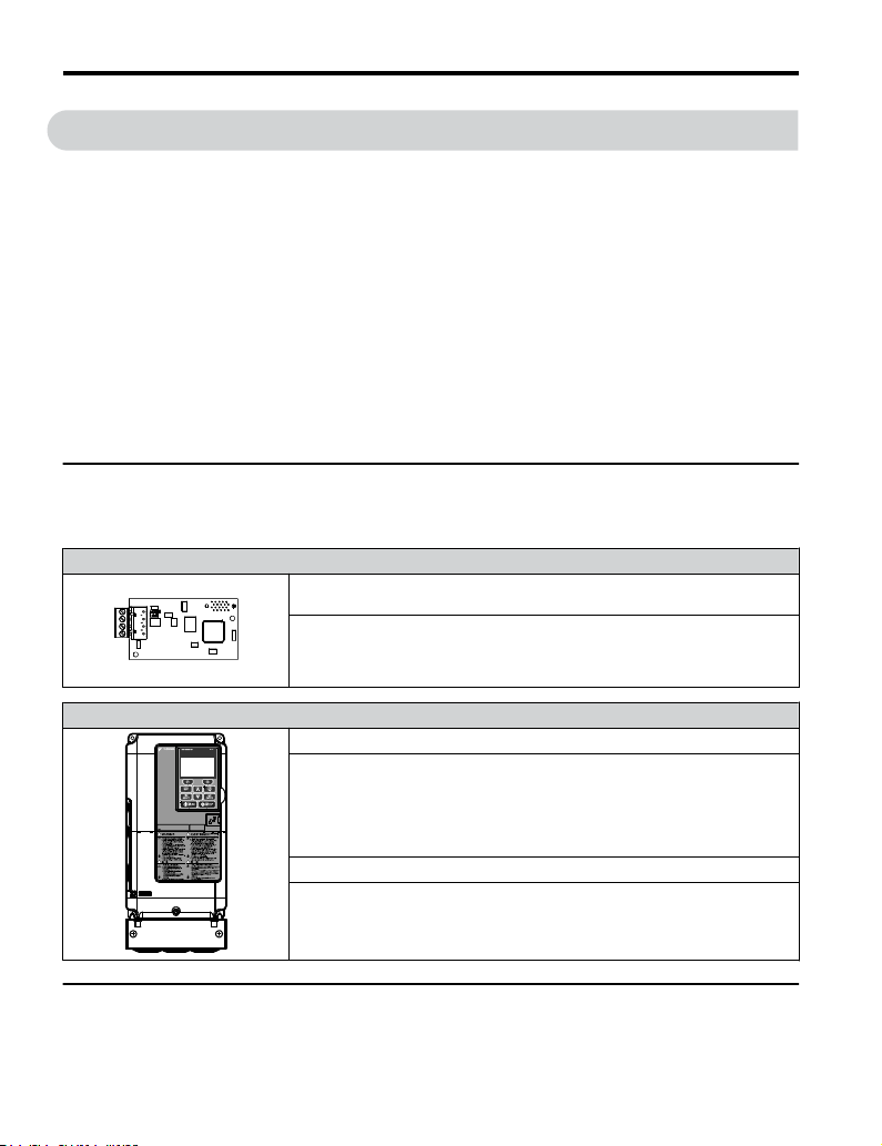
The following manuals are available for the SI-B3 option:
BACnet SI-B3 Option
Yaskawa AC Drive A1000 Option SI-B3 BACnet Installation & Technical
Manual (TOEPYEACOM08)
The Installation & Technical Manual is packaged with the SI-B3 option and
contains detailed information required to install the option and set up related drive
parameters. This manual also contains information about troubleshooting
procedures and BACnet supported objects.
Yaskawa Drive
A1000 Series AC Drive Quick Start Guide (TOEPC71061641)
Read this guide first. This guide is packaged together with the product and contains
basic information required to install and wire the drive. It also gives an overview
of fault diagnostics, maintenance, and parameter settings. The purpose of this
guide is to prepare the drive for a trial run with an application and for basic
operation. This manual is available for download on our documentation website,
www.yaskawa.com.
A1000 Series AC Drive Technical Manual (SIEPC71061641)
This manual provides detailed information on parameter settings, drive functions,
and MEMOBUS/Modbus specifications. Use this manual to expand drive
functionality and to take advantage of higher performance features. This manual
is available for download on our documentation website, www.yaskawa.com.
u
Terms
Note: Indicates supplemental information that is not related to safety messages.
4
YASKAWA TOEP YEACOM 08A A1000 Option BACnet MS/TP SI-B3 Installation & Technical Manual
Page 5
1 Preface and Safety
Drive: Yaskawa A1000-Series Drive
Option: Yaskawa AC Drive A1000 SI-B3 BACnet Option
u
Registered Trademarks
All trademarks are the property of their respective owners.
u
Supplemental Safety Information
Read and understand this manual before installing, operating, or servicing this option. The
option must be installed according to this manual and local codes.
The following conventions are used to indicate safety messages in this manual. Failure to heed
these messages could result in serious or possibly even fatal injury or damage to the products
or to related equipment and systems.
WARNING
Read and understand this manual before installing, operating or servicing this drive. The
drive must be installed according to this manual and local codes.
The following conventions are used to indicate safety messages in this manual. Failure to
heed these messages could result in serious or fatal injury or damage to the products or to
related equipment and systems.
DANGER
Indicates a hazardous situation, which, if not avoided, will result in death or serious
injury.
WARNING
Indicates a hazardous situation, which, if not avoided, could result in death or serious
injury.
WARNING! may also be indicated by a bold key word embedded in the text followed by an italicized safety
message.
YASKAWA TOEP YEACOM 08A A1000 Option BACnet MS/TP SI-B3 Installation & Technical Manual
5
Page 6
1 Preface and Safety
CAUTION
Indicates a hazardous situation, which, if not avoided, could result in minor or
moderate injury.
CAUTION! may also be indicated by a bold key word embedded in the text followed by an italicized safety
message.
NOTICE
Indicates a property damage message.
NOTICE: may also be indicated by a bold key word embedded in the text followed by an italicized safety
message.
General Safety
n
General Precautions
• The diagrams in this manual may be indicated without covers or safety shields to show details. Replace
the covers or shields before operating the drive and run the drive according to the instructions
described in this manual.
• Any illustrations, photographs, or examples used in this manual are provided as examples only and
may not apply to all products to which this manual is applicable.
• The products and specifications described in this manual or the content and presentation of the manual
may be changed without notice to improve the product and/or the manual.
• When ordering a new copy of the manual due to damage or loss, contact your Yaskawa representative
or the nearest Yaskawa sales office and provide the manual number shown on the front cover.
• If nameplate becomes worn or damaged, order a replacement from your Yaskawa representative or
the nearest Yaskawa sales office.
DANGER
Heed the safety messages in this manual.
Failure to comply will result in death or serious injury.
The operating company is responsible for any injuries or equipment damage resulting from
failure to heed the warnings in this manual.
6
YASKAWA TOEP YEACOM 08A A1000 Option BACnet MS/TP SI-B3 Installation & Technical Manual
Page 7

1 Preface and Safety
DANGER
Electrical Shock Hazard
Do not connect or disconnect wiring while the power is on.
Failure to comply will result in death or serious injury.
Failure to comply will result in death or serious injury. Before servicing, disconnect all
power to the equipment. The internal capacitor remains charged even after the power supply
is turned off. The charge indicator LED will extinguish when the DC bus voltage is below
50 Vdc. To prevent electric shock, wait for at least the time specified on the warning label
once all indicators are OFF, and then measure the DC bus voltage level to confirm it has
reached a safe level.
NOTICE
Observe proper electrostatic discharge procedures (ESD) when handling the drive and
circuit boards.
Failure to comply may result in ESD damage to the drive circuitry.
Do not perform a withstand voltage test on any part of the drive.
Failure to comply could result in damage to the sensitive devices within the drive.
Do not operate damaged equipment.
Failure to comply could result in further damage to the equipment.
Do not connect or operate any equipment with visible damage or missing parts.
Do not expose the drive to halogen group disinfectants.
Failure to comply may cause damage to the electrical components in the drive.
Do not pack the drive in wooden materials that have been fumigated or sterilized.
Do not sterilize the entire package after the product is packed.
YASKAWA TOEP YEACOM 08A A1000 Option BACnet MS/TP SI-B3 Installation & Technical Manual
7
Page 8

2 Product Overview
2 Product Overview
u
About this Product
The SI-B3 option connects an A1000 drives to a BACnet network and facilitates the exchange
of data.
This manual explains the handling, installation and specifications of this product. The SI-B3
option is a simple, networking solution that reduces the cost and time to wire and install factory
automation devices, while providing interchangeability of like components from multiple
vendors.
Drives can be monitored and controlled by a controller on a Building Automation and Control
network (BACnet) using RS-485 technology and MS/TP (Master-Slave/Token-Passing)
protocol. The drives conform to the BACnet application specific controller (B-ASC) device
profile.
Up to 127 drives can communicate on a single BACnet MS/TP network. If more drives or
BACnet devices are required, then a BACnet router is required to allow another MS/TP
network to be available with up to another 127 drives.
u
Applicable Models
The option can be used with the drive models in Table 1.
Table 1 Applicable Models
Drive Series
A1000
<1> See “PRG” on the drive nameplate for the software version number.
Drive Model Number
CIMR-Ao2Aoooo
CIMR-Ao4A0002o
to 4A0675o
CIMR-Ao5Aoooo
Software Version
VSA901017 and later
VSA905045 and later
VSA901017 and later
<1>
8
YASKAWA TOEP YEACOM 08A A1000 Option BACnet MS/TP SI-B3 Installation & Technical Manual
Page 9
NS MS
TX RX
MANUAL
3 Receiving
3 Receiving
Please perform the following tasks upon receipt of the option:
• Inspect the option for damage. Contact the shipper immediately if the option appears
damaged upon receipt.
• Verify receipt of the correct model by checking the model number printed on the name
plate of the option package.
• Contact your supplier if you have received the wrong model or the option does not function
properly.
u
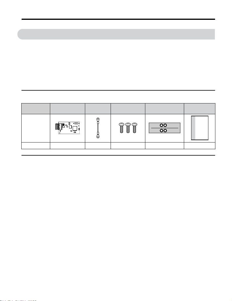
Option Package Contents
Description
–
Quantity 1 1 3 1 1
u
Tools Required for Installation
Option PCB
PN: UTC00043o
Ground
Wire
Screws (M3) LED Label
Installation
Manual
• A Phillips screwdriver (M3 metric/#1, #2 U.S. standard size) is required to install the option
and remove drive front covers. Screw sizes vary by drive capacity. Select a screwdriver
appropriate for the drive capacity.
• Diagonal cutting pliers. (required for some drive models)
• A small file or medium grit sandpaper. (required for some drive models)
• A straight-edge screwdriver (blade depth: 0.4 mm, width: 2.5 mm) is required to wire the
option terminal block.
Note: Tools required to prepare option networking cables for wiring are not listed in this manual.
YASKAWA TOEP YEACOM 08A A1000 Option BACnet MS/TP SI-B3 Installation & Technical Manual
9
Page 10
Underside
A
C
B
H
D
E
G
I
F
ON
4 Option Components
4 Option Components
u
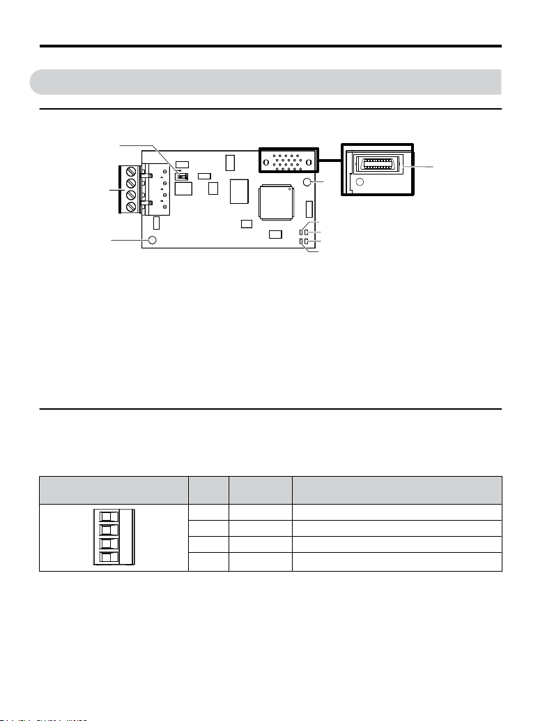
SI-B3 BACnet Option
A – Ground terminal and
installation hole
B – Terminal block TB1
C – Terminating resistor
switch S1
D – Connector (CN5)
E – Installation hole
<1> Connect the ground wire provided in the option shipping package during installation.
<2> Refer to Option LED Display on page 11 for details on the LEDs.
u
Terminal Block TB1
<1>
Figure 1 Option (Top View)
F –
G –
H –
I –
LED (NS)
LED (MS)
LED (RX)
LED (TX)
<2>
<2>
<2>
<2>
Refer to Table 2 for details on removable terminal block TB1 terminal descriptions.
Table 2 Option Terminal Descriptions
Terminal
10
YASKAWA TOEP YEACOM 08A A1000 Option BACnet MS/TP SI-B3 Installation & Technical Manual
Pin Signal Description
1 IG5 Isolated supply ground reference
2 + RX/TX (+) signal
3 - RX/TX (-) signal
4 SHLD Shield Ground
Page 11

4 Option Components
u
Option LED Display
The option has four LEDs.
Two bi-color Status LEDs:
• Module status (MS) red/green
• Network status (NS) red/green
Two BACnet LEDs:
• Transmit (TX) green
• Receive (RX) green
The operational states of the option LEDs after completion of the BACnet power-up diagnostic
LED sequence are described in Table 3. Wait at least 2 seconds for the power-up diagnostic
process to complete before verifying LED states.
Table 3 Option LED States
Name
MS
NS
Display
Color Status
– OFF Power supply OFF Power is not being supplied to the drive.
Green ON Normal operation
Green Flashing Standby/Initializing
Red Flashing Minor fault
Red ON Major fault
Green/Red Flashing Option self-test The option is in self-test mode.
– OFF Power supply OFF –
Green ON Connected
Green Flashing Not connected
Red Flashing Minor fault A minor recoverable fault has occurred.
Red ON Major fault
Green/Red Flashing Network test Power-up sequence and testing
Operating Status Remarks
The option is operating normally and
initialization is complete.
The option is in process of configuring or
waiting for configuration information.
The option has detected a recoverable
minor fault such as incomplete
configuration.
The option has detected an unrecoverable
major fault.
The device is currently communicating on
the network.
The device currently is not communicating,
but is correctly configured. The state is
“waiting” for communication to resume.
A non-recoverable major network fault has
occurred.
YASKAWA TOEP YEACOM 08A A1000 Option BACnet MS/TP SI-B3 Installation & Technical Manual
11
Page 12

4 Option Components
Name
TX
RX
Power-Up Diagnostics
n
Display
Color Status
– OFF
Green Flashing
– OFF
Green Flashing
Operating Status Remarks
No data being sent to the
network
Data being sent to the
network
No data seen on the
network
Data is seen on the
network
This node is not sending any data.
This node is sending network data.
The option is not physically connected to
the network or there is no network activity.
The option is connected to a network.
An LED test is performed each time the drive is powered up. The initial boot sequence may
take several seconds. After the LEDs have completed the diagnostic LED sequence, the option
is successfully initialized. The LEDs then assume operational conditions as shown in
Table 3.
Table 4 Power-Up Diagnostic LED Sequence
Sequence Module Status (MS) Network Status (NS) Time (ms)
1 Green OFF 250
2 Red OFF 250
3 Green OFF –
4 Green Green 250
5 Green Red 250
6 Green OFF –
12
YASKAWA TOEP YEACOM 08A A1000 Option BACnet MS/TP SI-B3 Installation & Technical Manual
Page 13
5 Installation Procedure
5 Installation Procedure
u
Section Safety
DANGER
Electrical Shock Hazard
Do not connect or disconnect wiring while the power is on.
Failure to comply will result in death or serious injury.
Before installing the option, disconnect all power to the drive. The internal capacitor remains
charged even after the power supply is turned off. The charge indicator LED will extinguish
when the DC bus voltage is below 50 Vdc. To prevent electric shock, wait at least five
minutes after all indicators are off and measure the DC bus voltage level to confirm safe
level.
WARNING
Electrical Shock Hazard
Do not operate equipment with covers removed.
Failure to comply could result in death or serious injury.
The diagrams in this section may show drives without covers or safety shields to show
details. Be sure to reinstall covers or shields before operating the drives and run the drives
according to the instructions described in this manual.
Do not remove covers or touch circuit boards while the power is on.
Failure to comply could result in death or serious injury.
Do not allow unqualified personnel to use equipment.
Failure to comply could result in death or serious injury.
Installation, maintenance, inspection, and servicing must be performed only by authorized
personnel familiar with installation, adjustment, and maintenance of this product.
YASKAWA TOEP YEACOM 08A A1000 Option BACnet MS/TP SI-B3 Installation & Technical Manual
13
Page 14

5 Installation Procedure
WARNING
Do not touch any terminals before the capacitors have fully discharged.
Failure to comply could result in death or serious injury.
Before installing the option, disconnect all power to the drive. The internal capacitor remains
charged even after the power supply is turned off. The charge indicator LED will extinguish
when the DC bus voltage is below 50 Vdc. To prevent electric shock, wait at least five
minutes after all indicators are off and measure the DC bus voltage level to confirm safe
level.
Do not use damaged wires, stress the wiring, or damage the wire insulation.
Failure to comply could result in death or serious injury.
Fire Hazard
Tighten all terminal screws to the specified tightening torque.
Loose electrical connections could result in death or serious injury by fire due to overheating
of electrical connections.
NOTICE
Observe proper electrostatic discharge procedures (ESD) when handling the drive and
circuit boards.
Failure to comply may result in ESD damage to the drive circuitry.
Do not use unshielded cable for control wiring.
Failure to comply may cause electrical interference resulting in poor system performance.
Use shielded, twisted-pair wires and ground the shield to the designated shield ground
location.
Check all the wiring to ensure that all connections are correct after installing the option
and connecting any other devices.
Failure to comply could result in damage to the option.
14
YASKAWA TOEP YEACOM 08A A1000 Option BACnet MS/TP SI-B3 Installation & Technical Manual
Page 15
I
J
K
M
A
L
D
F
G
C
E
B
H
NS MS
NS MS
TX RX
5 Installation Procedure
u
Prior to Installing the Option
Prior to installing the option, wire the drive, make necessary connections to the drive terminals,
and verify that the drive functions normally without the option installed. Refer to the Quick
Start Guide packaged with the drive for information on wiring and connecting the drive.
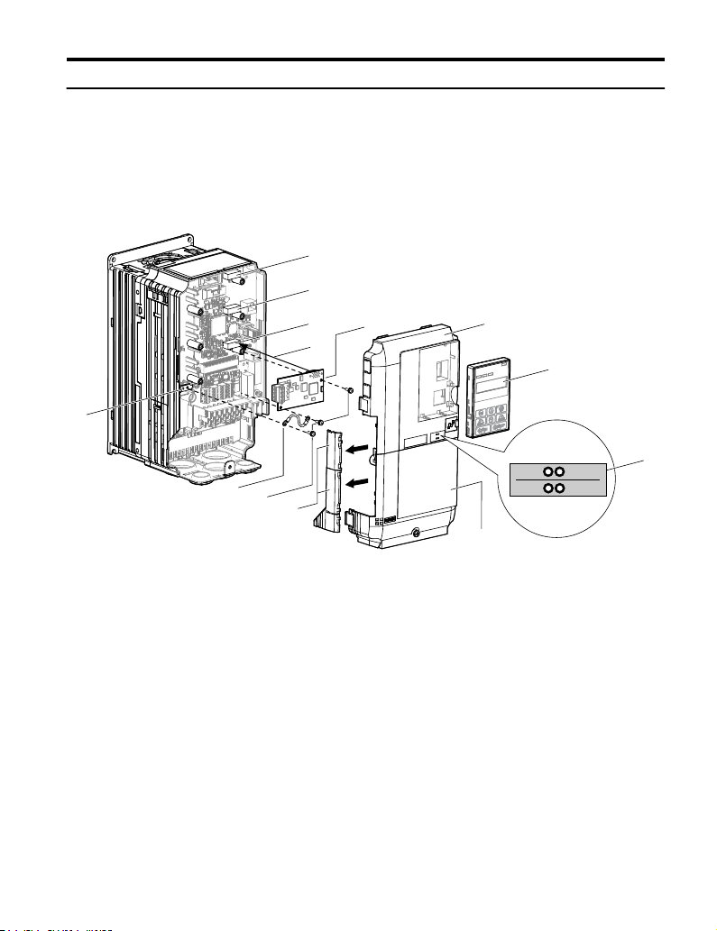
Figure 2 shows an exploded view of the drive with the option and related components for
reference.
A – Drive front cover
B – Digital operator
C – LED label
D – Drive terminal cover
E – Removable tabs for wire
F – Included screws
G – Ground wire
YASKAWA TOEP YEACOM 08A A1000 Option BACnet MS/TP SI-B3 Installation & Technical Manual
routing
Figure 2 Drive Components with Option
H – Drive grounding terminal
(FE)
I – Connector CN5-C
J – Connector CN5-B
K – Connector CN5-A
L – Insertion point for CN5
connector
M – SI-B3 option
15
Page 16

A
B
D
5 Installation Procedure
u
Installing the Option
Remove the front covers of the drive before installing the option. Refer to the drive Quick
Start Guide for directions on removing the front covers. Cover removal varies depending on
drive size. This option can be inserted only into the CN5-A connector located on the drive
control board.
Preparing the Drive
Shut off power to the drive, wait the appropriate amount of time for voltage to
1.
dissipate, then remove the digital operator (B) and front covers (A, D). Front cover
removal varies by model.
DANGER! Electrical Shock Hazard. Do not connect or disconnect wiring while the power is on.
Failure to comply will result in death or serious injury. Before installing the option, disconnect all
power to the drive. The internal capacitor remains charged even after the power supply is turned
off. The charge indicator LED will extinguish when the DC bus voltage is below 50 Vdc. To prevent
electric shock, wait at least five minutes after all indicators are off and measure the DC bus voltage
level to confirm safe level.
NOTICE: Damage to Equipment. Observe proper electrostatic discharge procedures (ESD) when
handling the option, drive, and circuit boards. Failure to comply may result in ESD damage to
circuitry.
Figure 3 Remove the Front Covers and Digital Operator
With the front covers and digital operator removed, apply the LED label (C) in the
2.
appropriate position on the drive top front cover (A).
16
YASKAWA TOEP YEACOM 08A A1000 Option BACnet MS/TP SI-B3 Installation & Technical Manual
Page 17

A
C
NS MS
TX RX
Figure 4 Apply the LED Label
NS MS
K
L
F
M
TX RX
Connecting Option and Ground Wire
Insert the option (M) into the CN5-A connector (K) located on the drive and fasten it
1.
using one of the included screws (F).
5 Installation Procedure
Figure 5 Insert the Option
YASKAWA TOEP YEACOM 08A A1000 Option BACnet MS/TP SI-B3 Installation & Technical Manual
17
Page 18

NS MS
F
G
M
H
TX RX
5 Installation Procedure
Connect the ground wire (G) to the ground terminal (H) using one of the remaining
2.
provided screws (F). Connect the other end of the ground wire (G) to the remaining
ground terminal and installation hole on the option (M) using the last remaining
provided screw (F) and tighten both screws to 0.5 ~ 0.6 N m or (4.4 ~ 5.3 in lbs).
Figure 6 Connect the Ground Wire
Wiring the Option
18
Note: There are two screw holes on the drive for use as ground terminals. When connecting three
options, two ground wires will need to share the same drive ground terminal.
Route the option wiring.
1.
Depending on the drive model, some drives may require routing the wiring through
the side of the front cover to the outside to provide adequate space for the wiring. In
these cases, using diagonal cutting pliers, cut out the perforated openings on the left
side of the drive front cover. Sharp edges along the cut out should be smoothed down
with a file or sand paper to prevent any damage to the wires.
Route the communication wiring inside the enclosure for drives that do not require
routing through the front cover. Refer to Table 5 and Figure 7 to determine the proper
wire routing by drive model.
YASKAWA TOEP YEACOM 08A A1000 Option BACnet MS/TP SI-B3 Installation & Technical Manual
Page 19

5 Installation Procedure
Table 5 Communication Wire Routing Selection
Drive Series Model
CIMR-Ao2A0004 to 0040;
A1000
A1000
CIMR-Ao4A0002 to 0023;
CIMR-Ao5A0003 to 0011
CIMR-Ao2A0056 and above;
CIMR-Ao4A0031 and above;
CIMR-Ao5A0023 and above
<1> Refer to Figure 7 for examples of the different wire routing techniques.
Wire Routing <1>
Through
Front Cover
Figure 7 (A) –
– Figure 7 (B)
Inside Drive
A
A – Route wires through the
openings provided on the
left side of the front
<1>
cover.
Figure 7 Wire Routing Examples
<1> The drive will not meet NEMA Type 1 requirements if wiring is exposed outside the enclosure.
Connect the BACnet communication cables to the option modular connector terminal
2.
B – Use the open space
provided inside the drive
to route option wiring.
block (TB1).
Note: Separate the communications cables from the main circuit cables and other wiring and power
YASKAWA TOEP YEACOM 08A A1000 Option BACnet MS/TP SI-B3 Installation & Technical Manual
cables. Use properly grounded shielded cables for the communication cables to prevent
problems caused by electrical interference.
B
19
Page 20

A1000
M
U/T1
V/T2
W/T3
R/L1
S/L2
T/L3
SI-B3
BACnet
Option
FE
CN5-A
CN1
TB1
IG5
+
SHLD
RX/TX (+) Signal
RX/TX (-) Signal
BACnet
Master
MotorPower
Router
IG5
+
-
SHLD
+
-
SHLD
Drive
SI-B3
BACnet
S1
ON
S1
OFF
IG5
+
-
SHLD
Drive
SI-B3
BACnet
S1
OFF
IG5
+
-
SHLD
Drive
SI-B3
BACnet
5 Installation Procedure
Connection Diagram
n
Figure 8 Connection Diagram
Figure 9 explains the wiring for multiple connections using BACnet communication.
20
Figure 9 Connection Diagram for Multiple Connections
YASKAWA TOEP YEACOM 08A A1000 Option BACnet MS/TP SI-B3 Installation & Technical Manual
Page 21

BACnet
Workstation
Drive Drive Drive
MS/TP
BACnet over Ethernet
Router
Router
A1000
CIMR-AU5A0009FAA
600V 3Phase 5.5kW/3.7kW
A1000
CIMR-AU5A0009FAA
600V 3Phase 5.5kW/3.7kW
A1000
CIMR-AU5A0009FAA
600V 3Phase 5.5kW/3.7kW
Drive Drive Drive
MS/TP
A1000
CIMR-AU5A0009FAA
600V 3Phase 5.5kW/3.7kW
A1000
CIMR-AU5A0009FAA
600V 3Phase 5.5kW/3.7kW
A1000
CIMR-AU5A0009FAA
600V 3Phase 5.5kW/3.7kW
5 Installation Procedure
Figure 10 Connecting Multiple Drives to a BACnet Workstation – System Overview
The two ends of the BACnet network must be terminated with a 120 ohm resistor between
the “+” and “-” and signals. The SI-B3 has a built in termination resistor that can be enabled
or disabled using DIP switch S1. If a drive is located at the end of a network line, enable the
termination resistor by setting DIP switch S1 to the ON position. Disable the termination
resistor on all slaves that are not located at the end of the network line by setting DIP switch
S1 to the OFF position (The factory setting for DIP switch S1 is OFF).
YASKAWA TOEP YEACOM 08A A1000 Option BACnet MS/TP SI-B3 Installation & Technical Manual
21
Page 22

D
A
B
NS MS
TX RX
5 Installation Procedure
Replacing the Drive Covers and Digital Operator
Replace and secure the front covers of the drive (A, D) and replace the digital operator
1.
(B).
Figure 11 Replace the Front Covers and Digital Operator
Note: Take proper precautions when wiring the option so that the front covers will easily fit back onto
u
the drive. Make sure no cables are pinched between the front covers and the drive when
replacing the covers.
BACnet Node Addressing
The BACnet node address is configurable by parameter F6-45 in the drive. This defines the
physical address of the drive on the MS/TP network. In addition, both the Device Object
Instance Identifier (parameters F6-48 and F6-49) and the Device Object Name are
configurable. These allow the drive to have a virtual address and simplify the controller
configuration.
After setting the addressing, a controller can initiate communication to the drive. The drive
will perform the specified function and then send a response back to the controller. The drive
will usually respond immediately, but may delay its response until it gets the token for
commands that may take extra local processing time.
22
YASKAWA TOEP YEACOM 08A A1000 Option BACnet MS/TP SI-B3 Installation & Technical Manual
Page 23

5 Installation Procedure
u
Electronic Protocol Implementation Conformance Statement (EPIC) Files
For easy network implementation of drives equipped with the SI-B3 option, an EPIC file can
be obtained from:
U.S.: http://www.yaskawa.com
Other areas: Contact a Yaskawa representative.
Refer to BACnet Protocol Implementation Conformance Statement (PICS) on page 42
for the SI-B3 PICS.
YASKAWA TOEP YEACOM 08A A1000 Option BACnet MS/TP SI-B3 Installation & Technical Manual
23
Page 24

6 Related Drive Parameters
6 Related Drive Parameters
The following parameters are used to set up the drive for operation with the option. Parameter
setting instructions can be found in the drive Quick Start Guide or Technical Manual.
Confirm proper setting of the all parameters in Table 6 before starting network
communications. After changing parameter settings, cycle power to the drive for the new
settings to take effect.
Table 6 Related Parameters
No. Name Description Values
Selects the frequency reference input source.
Frequency Reference
b1-01
Selection
<1>
Run Command
b1-02
Selection
F6-45 Drive Node Address
Communication
F6-46
Speed Selection
Drive Transmit Wait
F6-47
Time
BACnet Device
F6-48
Object Identifier 0
<2>
BACnet Device
F6-49
Object Identifier 1
<2>
<1> To start and stop the drive with the option master device using serial communications, set b1-02 to 3. To control
the drive frequency reference via the master device, set b1-01 to 3.
<2> These parameters set the Instance Identifier of the BACnet Device Object, where the F6-48 value is the least
significant word and the F6-49 value is the most significant word.
Example 1: Set the Device Object Instance Identifier of "1234". 1234 decimal is equal to 4D2H (hexadecimal).
Set F6-48 to 4D2H and F6-49 to 0.
Example 2: Set Device Object Instance Identifier to "1234567". 1234567 decimal is equal to 12D687H. Set
F6-48 to D687H and set F6-49 to 12H.
0: Operator - Digital preset speed d1-01 to d1-17
1: Terminals - Analog input terminal A1 or A2
2: MEMOBUS/Modbus communications
3: Option PCB
4: Pulse Input (Terminal RP)
Selects the run command input source.
0: Digital Operator - RUN and STOP keys
1: Digital input terminals S1 to S7
2: MEMOBUS/Modbus communications
3: Option PCB
Sets the BACnet MS/TP MAC address (physical node
address).
Sets the communication speed.
0: 1200 bps
1: 2400 bps
2: 4800 bps
3: 9600 bps
4: 19200 bps
5: 38400 bps
6: 57600 bps
7: 76800 bps
8: 115200 bps
Sets the time the drive waits after receiving data from a master
before transmitting response data.
Set the Instance Identifier of the BACnet Device Object, where
the F6-48 value is the least significant word.
Set the Instance Identifier of the BACnet Device Object, where
the F6-49 value is the most significant word.
Default: 1
Range: 0 to 4
(Set to 3 for BACnet)
Default: 1
Range: 0 to 3
(Set to 3 for BACnet)
Default: 1
Range: 0 to 127
Default: 3
Range: 0 to 8
Default: 5 ms
Range: 5 to 65
Default: 1
Range: 0 to FFFFH
Default: 0
Range: 0 to 3FH
24
YASKAWA TOEP YEACOM 08A A1000 Option BACnet MS/TP SI-B3 Installation & Technical Manual
Page 25

7 Troubleshooting
7 Troubleshooting
u
Drive-Side Error Codes
Drive-side error codes appear on the drive digital operator. Causes of the errors and corrective
actions are listed below. For additional error codes that may appear on the drive digital
operator, refer to the drive Technical Manual.
Faults
n
Both bUS (SI-B3 option communication error) and EF0 (External fault input from the SI-B3
option) can appear as an alarm or as a fault. When a fault occurs, the digital operator ALM
LED remains lit. When an alarm occurs, the ALM LED flashes.
If communication stops while the drive is running, use the following questions as a guide to
help remedy the fault:
• Is the option properly installed?
• Are the communication lines properly connected to the option? Are the wires loose?
• Is the controller program working? Has the controller/PLC CPU stopped?
• Did a momentary power loss interrupt communications?
Digital Operator Display Fault Name
Option Communication Error
bUS
Cause Possible Solution
No signal was received from the
PLC
Faulty communications wiring or
an existing short circuit
Communication data error
occurred due to electrical
inteference
The option card is damaged
• The connection was lost after establishing initial communication.
• Only detected when the run command frequency reference is assigned to an
option card.
• Check for faulty wiring.
• Correct the wiring.
• Check for disconnected cables and short circuits and repair as needed.
• Check the various options available to minimize the effects of noise.
• Counteract noise in the control circuit, main circuit, and ground wiring.
• Ensure that other equipment such as switches or relays do not cause electrical
inteference. Use surge absorbers if necessary.
• Use only recommended cables or other shielded line. Ground the shield on the
controller side or the drive input power side.
• Separate all communication wiring from drive power lines. Install an EMC
noise filter to the drive power supply input.
Replace the option card if there are no problems with the wiring and the error
continues to occur.
YASKAWA TOEP YEACOM 08A A1000 Option BACnet MS/TP SI-B3 Installation & Technical Manual
25
Page 26

7 Troubleshooting
The option card is not properly
connected to the drive
Digital Operator Display Minor Fault Name
EF0
Cause Possible Solutions
An external fault was received
from the PLC with F6-03 set to
3, which allows the drive to
continue running after an
external fault occurs.
There is a problem with the PLC
program.
Digital Operator Display Fault Name
oFA00
Cause Possible Solution
The option card installed into port
CN5-A is incompatible with the
drive
A PG option card is connected to
option port CN5-A
Digital Operator Display Fault Name
oFA01
Cause Possible Solution
The option card connection to port
CN5-A is faulty
• The connector pins on the option card do not line up properly with the
connector pins on the drive.
• Reinstall the option card.
Option Card External Fault
An external fault condition is present.
• Remove the cause of the external fault.
• Remove the external fault input from the PLC.
Check the PLC program and correct problems.
Option Card Connection Error at Option Port CN5-A
Option compatibility error
Check if the drive supports the option card to be installed. Contact Yaskawa for
assistance.
PG option cards are supported by option ports CN5-B and CN5-C only. Connect
the PG option card to the correct option port.
Option Card Fault at Option Port CN5-A
Option not properly connected
• Turn off the power and reconnect the option card.
• Check if the option card is properly plugged into the option port. Make sure
the card is fixed properly.
• If the option is not a communication option card, try to use the card in a different
option port. If the option card works properly in a different option port, CN5A is damaged, and the drive requires replacement. If the error persists (oFb01
or oFC01 occur), replace the option card.
Digital Operator Display Fault Name
to oFA03 to
26
,
oFA06
Option Card Error Occurred at Option Port CN5-A
oFA10, oFA11
YASKAWA TOEP YEACOM 08A A1000 Option BACnet MS/TP SI-B3 Installation & Technical Manual
Page 27

7 Troubleshooting
to oFA12 to
to
Option card or hardware is
damaged
Digital Operator Display Fault Name
The option card installed into port
CN5-B is incompatible with the
drive
A communication option card has
been installed in option port
CN5-B
Digital Operator Display Fault Name
An option card of the same type is
already installed in option port
CN5-A
An input option card is already
installed in option port CN5-A
oFA17
oFA30 to
oFA43
Cause Possible Solution
oFb00
Cause Possible Solution
oFb02
Cause Possible Solution
Option Card Connection Error (CN5-A)
Communication Option Card Connection Error (CN5-A)
• Cycle power to the drive.
• If the problem continues, replace the control board or the entire drive. Contact
Yaskawa or a Yaskawa representative for instructions on replacing the control
board.
Option Card Fault at Option Port CN5-B
Option compatibility error
Make sure the drive supports the option card to be installed. Contact Yaskawa for
assistance.
Communication option cards are only supported by option port CN5-A. It is not
possible to install more than one communication option.
Option Card Fault at Option Port CN5-B
Same type of option card is currently connected
Except for PG options, only one of each option card type can only be installed
simultaneously. Make sure only one type of option card is connected.
Install a communication option, a digital input option, or an analog input option.
More than one of the same type of card cannot be installed simultaneously.
Digital Operator Display Fault Name
oFC00
Cause Possible Solution
The option card installed into port
CN5-C is incompatible with the
drive
A communication option card has
been installed in option port
CN5-C
YASKAWA TOEP YEACOM 08A A1000 Option BACnet MS/TP SI-B3 Installation & Technical Manual
Option Card Connection Error at Option Port CN5-C
Option compatibility error
Confirm that the drive supports the option card to be installed. Contact Yaskawa
for assistance.
Communication option cards are only supported by option port CN5-A. It is not
possible to install more than one communication option.
27
Page 28

7 Troubleshooting
Digital Operator Display Fault Name
oFC02
Cause Possible Solution
An option card of the same type is
already installed in option port
CN5-A or CN5-B.
An input option card is already
installed in option port CN5-A or
CN5-B.
Three PG option boards are
installed.
Minor Faults and Alarms
n
Digital Operator Display Minor Fault Name
CALL
Cause Possible Solutions
Communications wiring is
faulty, there is a short circuit, the
wiring is incorrect , or the
connections are poor.
Programming error on the master
side.
Communications circuitry is
damaged.
Termination resistor setting is
incorrect.
Option Card Fault at Option Port CN5-C
Same type of option card is currently connected
Except for PG options, only one of each option card type can only be installed
simultaneously. Make sure only one type of option card is connected.
Install a communication option, a digital input option, or an analog input option.
More than one of the same type of card cannot be installed simultaneously.
A maximum of two PG option boards can be used simultaneously. Remove the
PG option board installed into option port CN5-A.
Serial Communication Transmission Error
Communication has not yet been established.
• Check for wiring errors.
• Correct the wiring.
• Check for disconnected cables and short circuits. Repair as needed.
Check communications at start-up and correct programming errors.
• Perform a self-diagnostics check.
• If the problem continues, replace either the control board or the entire drive. For
instructions on replacing the control board, contact Yaskawa or your nearest sales
representative.
Install a termination resistor at both ends of a communication line. Set the internal
termination resistor switch correctly on slave drives. Place DIP switch S1 to the ON
position.
28
YASKAWA TOEP YEACOM 08A A1000 Option BACnet MS/TP SI-B3 Installation & Technical Manual
Page 29

7 Troubleshooting
Communication Errors
n
Errors that may occur when accessing drive parameters using the BACnet objects are shown
in Table 7.
Table 7 MEMOBUS to BACnet Error Conversion
Error Code Description
03d
27d
37d
40d
BN_ERR_DEVICE_IS_BUSY
Writing to a parameter was attempted while the drive was saving parameters to non-volatile
memory.
BN_ERR_READ_ACCESS_DENIED
Invalid parameter register number used when reading.
BN_ERR_VALUE_OUT_OF_RANGE
Value written to the parameter is out of the valid range.
BN_ERR_WRITE_ACCESS_DENIED
An invalid parameter register number was used when writing.
Writing to a parameter was attempted while the drive was in a mode that disables writing (i.e.,
writing while the drive was Auto-Tuning).
Writing to a parameter was attempted while the DC Bus had an Undervoltage (Uv) fault.
YASKAWA TOEP YEACOM 08A A1000 Option BACnet MS/TP SI-B3 Installation & Technical Manual
29
Page 30

8 Drive Operations by BACnet
8 Drive Operations by BACnet
The drive operations that can be performed by BACnet communication depend on drive
parameter settings. This section explains the functions that can be used and related parameter
settings.
u
Observing the Drive Operation
A controller can perform the following actions with BACnet communications at any time
regardless of parameter settings:
• observe drive status and drive control terminal status from a controller
• read and write parameters
• set and reset faults
• set multi-function inputs.
Note:
u
Select an external reference and adjust the parameters in Table 8 accordingly to start and stop
the drive or set the frequency reference using BACnet communications.
Reference Source Parameter Name Required Setting
External Reference 1
External Reference 2
Input settings from the input terminals So and from BACnet communications are both linked by a logical
OR operation.
Controlling the Drive
Table 8 Setting Parameters for Drive Control from BACnet
b1-01 Frequency Reference Selection 1 3
b1-02 Run Command Selection 1 3
b1-15 Frequency Reference Selection 2 3
b1-16 Run Command Selection 2 3
30
YASKAWA TOEP YEACOM 08A A1000 Option BACnet MS/TP SI-B3 Installation & Technical Manual
Page 31

9 Communications Timing
9 Communications Timing
To prevent a communications overrun in the slave drive, the master should wait a certain time
between sending messages to the same drive. In the same way, the slave drive must wait before
sending response messages to prevent an overrun in the master. This section explains the
message timing.
u
Command Messages from Master to Drive
The master must wait for a specified time between receiving a response and resending the
same type of command to the same slave drive to prevent overrun and data loss. The minimum
wait time depends on the command as shown in Table 9.
Table 9 Minimum Wait Time for Sending Messages
Command
Type
• Control command (Run, Stop)
1
• Set inputs/outputs
• Read monitors and parameter values
2 Write parameters
3 Save changes using an Enter command
4
<1> If the drive receives command type 1 data during the minimum wait time, it will perform the command and then
respond. However, if it receives a command type 2 or 3 during that time, either a communication error will result
or the command will be ignored.
Enter with storage to drive EEPROM after
initialization
PLC→Drive PLC→DriveDrive→PLC
Command message Response message Command message
Example Minimum Wait Time
<1>
5 ms
H5-11 = 0: 50 ms
H5-11 = 1: 200 ms
<1>
200 ms to 2 s, depending on
the number of parameters that
were changed
<1>
5 s
Time
24 bit length
Figure 12 Minimum Wait Time for Sending Messages
YASKAWA TOEP YEACOM 08A A1000 Option BACnet MS/TP SI-B3 Installation & Technical Manual
Master Send
Wait Time
31
Page 32

9 Communications Timing
Set a timer in the master to check how long it takes for the slave drive(s) to respond to the
master. If no response is received within a certain amount of time, the master should try
resending the message.
u
Response Messages from Drive to Master
If the drive receives a command from the master, it will process the data received and wait
for the time set in F6-47 until it responds. Increase F6-47 if the drive response causes overrun
in the master.
PLC→Drive PLC→DriveDrive→PLC
Command message Response message Command message
Time
24 bit length
32
YASKAWA TOEP YEACOM 08A A1000 Option BACnet MS/TP SI-B3 Installation & Technical Manual
H5-06
setting
Figure 13 Minimum Response Wait Time
Page 33

10 BACnet Objects Supported
10 BACnet Objects Supported
u
Present Value Access
The Present Value (PV) of BACnet objects can be read. In addition, some PVs can be written
or commanded. A commandable PV is similar to writing the value, but the value is actually
written into a priority array. The value occupying the highest priority in the array will be used
by the drive. The convention for showing how the PV is accessed is shown in Table 10 and
will be noted for the PV of each object.
Table 10 Present Value Access Values
PV Access Name Description
C Commandable
R Readable Value is read-only
W Writable Value written to the drive
u
Supported Properties of Objects
Property
Object_Identifier Yes Yes Yes Yes Yes Yes Yes
Object_Name Yes Yes Yes Yes Yes Yes Yes
Object_Type Yes Yes Yes Yes Yes Yes Yes
System_Status Yes – – – – – –
Vendor_Name Yes – – – – – –
Vendor_Identifier Yes – – – – – –
Model_Name Yes – – – – – –
Firmware_Revision Yes – – – – – –
Protocol_Version Yes – – – – – –
Protocol_Revision Yes – – – – – –
Protocol_Services_Supported Yes – – – – – –
Protocol_Object_Types_Supported Yes – – – – – –
Object_List Yes – – – – – –
Max_ADPU_Length_Accepted Yes – – – – – –
Segmentation_Supported Yes – – – – – –
Value written to a priority array. The highest priority value in the array is then
written to the drive.
Table 11 Object Properties
Object Type
Device
Analog
Input
Analog
Output
Analog
Value
Binary
Input
Binary
Output
Binary
Value
YASKAWA TOEP YEACOM 08A A1000 Option BACnet MS/TP SI-B3 Installation & Technical Manual
33
Page 34

10 BACnet Objects Supported
Object Type
Property
ADPU_Timeout Yes – – – – – –
Number_Of_ADPU_Retries Yes – – – – – –
Max_Masters Yes – – – – – –
Max_Info_Frames Yes – – – – – –
Device_Address_Binding Yes – – – – – –
Database_Revision Yes – – – – – –
Present_Value – Yes Yes Yes Yes Yes Yes
Status_Flags – Yes Yes Yes Yes Yes Yes
Event_State – Yes Yes Yes Yes Yes Yes
Reliability – Yes Yes Yes Yes Yes Yes
Out_Of_Service – Yes Yes Yes Yes Yes Yes
Units – Yes Yes Yes – – –
Priority_Array – –
Relinquish_Default – –
Polarity – – – – Yes Yes –
Inactive_Text – – – – Yes Yes Yes
Active_Text – – – – Yes Yes Yes
<1> For Commandable Object Instances only.
u
Analog Input Objects
Object ID Object Name
AI1 Analog Input 1 Level 004EH XXXX.X – % R
AI2 Analog Input 2 Level 004FH XXXX.X – % R
AI3 Not Used AI3 – – – – –
AI4 Not Used AI4 – – – – –
AI5 Not Used AI5 – – – – –
AI6 Display Format o1-03 0502H XXXXX – – R
AI7 Scale Format b5-20 01E2H XXXXX – – R
AI8 Inverter Model o2-04 0508F XXXXX – – R
AI9 Rated Current n9-01 05D0H XXXX.X – Amps R
Device
Analog
Table 12 Analog Input Objects
Modbus
Address
Analog
Input
Output
Yes
Yes
Precision Range Units PV Access
<1>
<1>
Analog
Yes
Yes
Value
<1>
<1>
Binary
Binary
Input
Output
– Yes Yes
– Yes Yes
Binary
Value
34
YASKAWA TOEP YEACOM 08A A1000 Option BACnet MS/TP SI-B3 Installation & Technical Manual
Page 35

10 BACnet Objects Supported
u
Analog Output Objects
Table 13 Analog Output Objects
Object ID Object Name
AO1 Analog Output 1 Level 0007H XXXX.X 0 to 100.0 % C
AO2 Analog Output 2 Level 0008H XXXX.X 0 to 100.0 % C
u
Analog Value Objects
Object ID Object Name
AV1 Operation Cmd 0001H XXXXX 0 to 65535 – C
AV2 Frequency Cmd 0002H
AV3 PI Setpoint Cmd 0006H XXX.XX
AV4 MF Output 1 Cmd 0009H XXXXX 0 to 255 – C
AV5 Reference Select Cmd 000FH XXXXX – – C
AV6 Drive Status 0020H XXXXX – – R
AV7 Fault Details 0021H XXXXX – – R
AV8 Data Link Status 0022H XXXXX – – R
AV9 Frequency Reference 0040H
AV10 Output Frequency 0041H
AV11 Output Voltage 0045H XXXX.X – Volts R
AV12 Output Current 0026H XXXX.X – Amps R
AV13 Output Power 0047H
AV14 Torque Reference 0048H XXXX.X – % R
AV15 MF Input Status 002BH XXXXX – – R
Modbus
Address
Table 14 Analog Value Objects
Modbus
Address
Precision Range Units PV Access
Precision Range Units PV Access
XXX.XX
Depends on
o1-03
XXX.XX
Depends on
o1-03
XXX.XX
Depends on
o1-03
XXXX.X
(for drives
rated above
11 kVA)
XXX.XX
(for drives
rated 11
kVA or
lower)
0.00 to
600.00
0.00 to
100.00
–
–
– kW R
Hz
Depends on
o1-03
% C
Hz
Depends on
o1-03
Hz
Depends on
o1-03
C
R
R
YASKAWA TOEP YEACOM 08A A1000 Option BACnet MS/TP SI-B3 Installation & Technical Manual
35
Page 36

10 BACnet Objects Supported
Object ID Object Name
AV16 Drive Status 2 002CH XXXXX – – R
AV17 MF Output Status 002DH XXXXX – – R
AV18 DC Bus Voltage 0031H XXXX.X – Volts R
AV19 PI Feedback Level 0038H XXXX.X – % R
AV20 PI Input Level 0039H XXXX.X – % R
AV21 PI Output Level 003AH XXXX.X – % R
AV22 CPU Software 004DH XXXXX – – R
AV23 Flash Number 005BH XXXXX – – R
AV24 Comm Error Detail 003DH XXXXX – – R
AV25 kVA Setting 0508H XXXXX – – R
AV26 Control Method 0102H XXXXX – – R
AV27 Accel Time 0200H
AV28 Decel Time 0201H
<1>
AV29
AV30
<1> Refer to Accessing Drive Parameters and the Enter Command on page 40 for an explanation of how to read
Parameter Number – XXXXX 0 to FFFFH – W
<1>
Parameter Data – XXXXX 0 to FFFFH – W
and write drive parameters not listed in the analog or binary objects.
Modbus
Address
Precision Range Units PV Access
XXXX.X
(when
C1-10 = 1)
XXX.XX
(when
C1-10 = 0)
XXXX.X
(when
C1-10 = 1)
XXX.XX
(when
C1-10 = 0)
0.0 to 6000.0
(when
C1-10 = 1)
0.00 to
600.00
(when
C1-10 = 0)
0.0 to 6000.0
(when
C1-10 = 1)
0.00 to
600.00
(when
C1-10 = 0)
Sec W
Sec W
u
Binary Input Objects
Table 15 Binary Input Objects
Object ID Object Name
BI1 Input Terminal 1 002BH:bit 0 ON OFF R
BI2 Input Terminal 2 002BH:bit 1 ON OFF R
BI3 Input Terminal 3 002BH:bit 2 ON OFF R
BI4 Input Terminal 4 002BH:bit 3 ON OFF R
36
YASKAWA TOEP YEACOM 08A A1000 Option BACnet MS/TP SI-B3 Installation & Technical Manual
Modbus
Address
Active Text
Inactive
Text
PV Access
Page 37

10 BACnet Objects Supported
Object ID Object Name
BI5 Input Terminal 5 002BH:bit 4 ON OFF R
BI6 Input Terminal 6 002BH:bit 5 ON OFF R
BI7 Input Terminal 7 002BH:bit 6 ON OFF R
BI8 Multi-Function Out 1 0020H:bit 5 ON OFF R
BI9 Multi-Function Out 2 0020H:bit 6 ON OFF R
u
Binary Output Objects
Table 16 Binary Output Objects
Object ID Object Name
BO1 MF Output M1-M2 0009H:bit 0 ON OFF C
BO2 MF Output M3-M4 0009H:bit 1 ON OFF C
BO3 MF Output M5-M6 0009H:bit 2 ON OFF C
BO4 Ref Sel: PI Setpoint 000FH:bit 1 ON OFF C
BO5 Ref Sel: Term S5 IN 0001H: bit 8 ON OFF C
BO6 Ref Sel: Term S6 IN 0001H: bit 9 ON OFF C
BO7 Refl Sel: Term S7 IN 0001H: bit 10 ON OFF C
u
Binary Value Objects
Table 17 Binary Value Objects
Object ID Object Name
BV1 Run FWD Cmd 0001H:bit 0 RUN OFF C
BV2 Run REV Cmd 0001H:bit 1 REV OFF C
BV3 Ext Fault Cmd 0001H:bit 2 FAULT OFF C
BV4 Fault Reset Cmd 0001H:bit 3 RESET OFF C
BV5 Com Net Cmd 0001H:bit 4 COM LOCAL C
BV6 Com Cntrl Cmd 0001H:bit 5 COM LOCAL C
BV7 MF Input 3 Cmd 0001H:bit 6 ON OFF C
BV8 MF Input 4 Cmd 0001H:bit 7 ON OFF C
BV9 MF Input 5 Cmd 0001H:bit 8 ON OFF C
BV10 MF Input 6 Cmd 0001H:bit 9 ON OFF C
BV11 MF Input 7 Cmd 0001H:bit 10 ON OFF C
BV12 Set Fault Contact Cmd 0009H:bit 6 ENABLE OFF C
Modbus
Address
Modbus
Address
Modbus
Address
Active Text
Active Text
Active Text
Inactive
Text
Inactive
Text
Inactive
Text
PV Access
PV Access
PV Access
YASKAWA TOEP YEACOM 08A A1000 Option BACnet MS/TP SI-B3 Installation & Technical Manual
37
Page 38

10 BACnet Objects Supported
Object ID Object Name
BV13 RUN-STOP 0020H:bit 0 RUN OFF R
BV14 REV-FWD 0020H:bit 1 REV FWD R
BV15 READY 0020H:bit 2 READY OFF R
BV16 FAULT 0020H:bit 3 FAULTED OFF R
BV17 Data Set Error 0020H:bit 4 ERROR OFF R
BV18 Overcurrent – Gnd Fault 0021H:bit 0 OC-GF OFF R
BV19 Main Ckt Overvoltage 0021H:bit 1 OV OFF R
BV20 Drive Overload 0021H:bit 2 OL2 OFF R
BV21 Drive Overheat 0021H:bit 3 OH1-OH2 OFF R
BV22 Fuse Blown 0021H:bit 5 PUF OFF R
BV23 PI Feedback Loss 0021H:bit 6 FBL OFF R
BV24 External Fault 0021H:bit 7 EF0-EF OFF R
BV25 Hardware Error 0021H:bit 8 CPF OFF R
BV26 Mtr Ovrld-OvrTorque 0021H:bit 9 OL1-OL3 OFF R
BV27 Overspeed 0021H:bit 10 OS-DEV OFF R
BV28 Main Ckt Undervoltage 0021H:bit 11 UV OFF R
BV29 MCU, Cntl Pwr Sy Err 0021H:bit 12 UV1-2-3 OFF R
BV30 Output Phase Loss 0021H:bit 13 LF OFF R
BV31 Communication Error 0021H:bit 14 CE OFF R
BV32 Operator Disconnect 0021H:bit 15 OPR OFF R
BV33 Operating 002CH:bit 0 OPERATING OFF R
BV34 Zero Speed 002CH:bit 1 ON OFF R
BV35 Frequency Agree 002CH:bit 2 ON OFF R
BV36 Desired Freq Agree 002CH:bit 3 ON OFF R
BV37 Frequency Detect 1 002CH:bit 4 ON OFF R
BV38 Frequency Detect 2 002CH:bit 5 ON OFF R
BV39 Drv Startup Complete 002CH:bit 6 ON OFF R
BV40 Low Voltage Detect 002CH:bit 7 ON OFF R
BV41 Base Block 002CH:bit 8 ON OFF R
BV42 Frequency Ref Mode 002CH:bit 9 COM LOCAL R
BV43 Run Command Mode 002CH:bit 10 COM LOCAL R
BV44 Overtorque Detect 002CH:bit 11 ON OFF R
BV45 Frequency Refer Lost 002CH:bit 12 ON OFF R
BV46 Retry Error 002CH:bit 13 ON OFF R
Modbus
Address
Active Text
Inactive
Text
PV Access
38
YASKAWA TOEP YEACOM 08A A1000 Option BACnet MS/TP SI-B3 Installation & Technical Manual
Page 39

10 BACnet Objects Supported
Object ID Object Name
BV47 Modbus Comms Error 002CH:bit 14 ON OFF R
BV48 Modbus Timeout Error 002CH:bit 15 ON OFF R
BV49 CRC Error 003DH:bit 0 ON OFF R
BV50 Invalid Data Length 003DH:bit 1 ON OFF R
BV51 Parity Error 003DH:bit 3 ON OFF R
BV52 Overrun Error 003DH:bit 4 ON OFF R
BV53 Framing Error 003DH:bit 5 ON OFF R
BV54 Timeout Error 003DH:bit 6 ON OFF R
<1>
BV55
BV56
BV57 Drive Comms Error - ON OFF R
<1> Refer to Accessing Drive Parameters and the Enter Command on page 40 for an explanation of how to read
and write drive parameters not listed in the analog or binary objects.
u
Device Object
Parameter Accept 0910H:bit 0 ON OFF W
<1>
Parameter Enter 0900H:bit 0 ON OFF W
Modbus
Address
Active Text
Inactive
Text
PV Access
The Device Object fully describes the BACnet device to the network. Notable is that the
Device Object Instance ID and the Device Object Name are configurable.
The Device Object Instance ID is a unique internetwork-wide numerical value. It is a 22-bit
value that can range from 0 to 4,194,303. It is configurable by parameters F6-48 and F6-49.
Any changes to these parameters will not take effect until the power is cycled to the drive.
The Device Object Name is a unique internetwork-wide character string. It is a 20-character
string. It is writable from the BACnet network. Any new string written will not take effect
until the power is cycled to the drive.
YASKAWA TOEP YEACOM 08A A1000 Option BACnet MS/TP SI-B3 Installation & Technical Manual
39
Page 40

11 Accessing Drive Parameters and the Enter Command
11 Accessing Drive Parameters and the
Enter Command
u
Reading Drive Parameters
Reading drive parameters not listed in the analog or digital objects is accomplished using
AV29 and AV30 as shown below:
In decimal, write the desired Modbus register to AV29.
1.
In decimal, read the value at the given register from AV30.
2.
For example, to read the Frequency Reference Upper Limit, read from parameter d2-01.
Parameter d2-01 is located at Modbus register 0289H, which is decimal 649.
Set AV29 to “649”
Read AV30 to get the value.
u
Writing Drive Parameters
Writing drive parameters not listed in the analog or digital objects is accomplished using
AV29, AV30, and BV55 or BV56 as shown below:
In decimal, write the desired Modbus register to AV29.
1.
In decimal, write the value to be written into AV30.
2.
At this point the value is pending. One of two actions must be taken to complete the
3.
writing process:
Set BV55 to “ON” to move data to active memory.
Set BV56 to “ON” to move data into active memory and save to non-volatile memory.
For example, to reset the KWH Monitor, write a value of “1” to parameter o1-12.
Parameter o1-12 is located at Modbus register 0512H, which is decimal 1298.
Set AV29 to “1298”
Set AV30 to “1”
Set BV55 to “ON”.
40
YASKAWA TOEP YEACOM 08A A1000 Option BACnet MS/TP SI-B3 Installation & Technical Manual
Page 41

11 Accessing Drive Parameters and the Enter Command
u
Enter Command
Enter Commands are only required when using AV29 and AV30 to write drive parameters.
An Enter command is not required when reading or writing to the other BACnet objects.
When writing parameters to the drive from a controller using BACnet communications, an
Enter command must be issued to enable these parameters. This section describes the types
and functions of the Enter commands.
Enter Command Types
n
The drive supports two types of Enter commands as shown in Table 18.
Table 18 Enter Command Types
BACnet Object Modbus Address Description
BV55 (Write “ON”) 0910H (bit 0)
BV56 (Write “ON”) 0900H (bit 0)
Note: The EEPROM can only be written to 100,000 times, so it is recommended to limit the number of times
writing to the EEPROM. The Enter command registers 0900H and 0910H are write-only and if these
registers are read, the register address will be invalid. However, BACnet objects BV55 and BV56 can
be read without error.
Writes data in the active RAM only. Parameter changes are lost
when the drive is shut off.
Simultaneously writes data into the EEPROM (non-volatile
memory) of the drive and enables the data in active RAM.
Parameter changes remain after cycling power.
YASKAWA TOEP YEACOM 08A A1000 Option BACnet MS/TP SI-B3 Installation & Technical Manual
41
Page 42

12 BACnet Protocol Implementation Conformance Statement (PICS)
12 BACnet Protocol Implementation
Conformance Statement (PICS)
Date: 08/02/2011
Vendor Name: Yaskawa
Product Name: AC Motor Controller
Product Model Number: SI-B3
Application Software Version: VST80026x Firmware Revision: 1.0 BACnet Protocol
Revision: 4
Product Description: The Yaskawa SI-B3 BACnet option connects an A1000 Drive to a
standard BACnet MS/TP network. The A1000 may be fully controlled and monitored over
BACnet. All drive parameters are available for reading and writing.
BACnet Standardized Device Profile (Annex L):
BACnet Operator Workstation (B-OWS)
BACnet Building Controller (B-BC)
BACnet Advanced Application Controller (B-AAC)
■BACnet Application Specific Controller (B-ASC)
BACnet Smart Sensor (B-SS)
BACnet Smart Actuator (B-SA)
List all BACnet Interoperability Building Blocks Supported (Annex K):
• Data Sharing-ReadProperty-B (DS-RP-B)
• Data Sharing-WriteProperty-B (DS-WP-B)
• Data Sharing - ReadProperty Multiple - B (DS-RPM-B)
• Data Sharing - WriteProperty Multiple - B (DS-WPM-B)
• Device Management-Dynamic Device Binding-B (DM-DDB-B)
• Device Management-Dynamic Object Binding-B (DM-DOB-B)
• Device Management-DeviceCommunicationControl-B (DM-DCC-B)
• Device Management-ReinitializeDevice-B (DM-RD-B)
Segmentation Capability:
Segmented requests supported Window Size____
Segmented responses supported Window Size____
42
YASKAWA TOEP YEACOM 08A A1000 Option BACnet MS/TP SI-B3 Installation & Technical Manual
Page 43

12 BACnet Protocol Implementation Conformance Statement (PICS)
Standard Object Types Supported:
• Device Object
• Analog Input Object
• Analog Output Object
• Analog Value Object
• Binary Input Object
• Binary Output Object
• Binary Value Object
Data Link Layer Options:
BACnet IP, (Annex J)
BACnet IP, (Annex J), Foreign Device
ISO 8802-3, Ethernet (Clause 7)
ANSI/ATA 878.1, 2.5 Mb. ARCNET (Clause 8)
ANSI/ATA 878.1, RS-485 ARCNET (Clause 8), baud rate(s)____
■ MS/TP master (Clause 9), baud rate(s): 9600bps, 19200bps, 38400bps, 76800bps.
MS/TP slave (Clause 9), baud rate(s):____
Point-To-Point, EIA 232 (Clause 10), baud rate(s):____
Point-To-Point, modem, (Clause 10), baud rate(s):____
LonTalk, (Clause 11), medium:____
Other:
Device Address Binding:
Is static device binding supported? (This is currently necessary for two-way communication
with MS/TP slaves and certain other devices.) Yes ■No
Networking Options:
Router, Clause 6 - List all routing configurations, e.g., ARCNET-Ethernet, Ethernet-MS/
TP, etc.
Annex H, BACnet Tunneling Router over IP
BACnet/IP Broadcast Management Device (BBMD)
Does the BBMD support registrations by Foreign Devices? Yes ■No
YASKAWA TOEP YEACOM 08A A1000 Option BACnet MS/TP SI-B3 Installation & Technical Manual
43
Page 44

12 BACnet Protocol Implementation Conformance Statement (PICS)
Character Sets Supported:
Indicating support for multiple character sets does not imply that they can all be supported
simultaneously.
■ ANSI X3.4 IBM /Microsoft DBCS ISO 8859-1 ISO 10646 (UCS-2) ISO
10646 (UCS-4) JIS C 6226
If this product is a communication gateway, describe the types of non-BACnet
equipment/networks(s) that the gateway supports:
Not supported
44
YASKAWA TOEP YEACOM 08A A1000 Option BACnet MS/TP SI-B3 Installation & Technical Manual
Page 45

13 Specifications
Table 19 Option Specifications
Item Specification
Model SI-B3 option
13 Specifications
Interface
Option Conformance BTL certified
Connector Type 4-pin removable terminal block
Max Number of Drives 127 per MS/TP network segment
Protocol BACnet MS/TP
Communication Speed 1200, 2400, 4800, 9600,19200, 38400, 57600, 76800, 115200 bps
Ambient Temperature
Humidity 95% relative humidity (non-condensing)
Storage Temperature
Area of Use Indoors
Altitude
MS/TP (Master-Slave/Token-Passing)
RS-485
-10 to +60 °C
-20 to +85 °C
Up to 1000 meters without derating, up to 3000 m with output current and voltage
derating.
YASKAWA TOEP YEACOM 08A A1000 Option BACnet MS/TP SI-B3 Installation & Technical Manual
45
Page 46

Revision History
Example:
The revision dates and the numbers of the revised manuals appear on the bottom of the back cover.
MANUAL NO.
Published in U.S.A. September 2012 11-5
Date of Publication
Revision
Number
SIEP C710616 45B
Date of
publication
1
Revision number
Date of
original publication
Section Revised Content
May 2013 <1> Chapter 10 Table 14, Analog Value Objects, revised to show correct values.
August 2011 - - First Edition
46
YASKAWA TOEP YEACOM 08A A1000 Option BACnet MS/TP SI-B3 Installation & Technical Manual
Page 47

Page 48

1
YASKAWA AC Drive - A1000 Option
BACnet MS/TP
Installation & Technical Manual
YASKAWA AMERICA, INC.
2121 Norman Drive South, Waukegan, IL 60085, U.S.A.
Phone: (800) YASKAWA (927-5292) or 1-847-887-7000 Fax: 1-847-887-7310
http://www.yaskawa.com
DRIVE CENTER (INVERTER PLANT)
2-13-1, Nishimiyaichi, Yukuhashi, Fukuoka, 824-8511, Japan
Phone: 81-930-25-3844 Fax: 81-930-25-4369
http://www.yaskawa.co.jp
YASKAWA ELECTRIC CORPORATION
New Pier Takeshiba South Tower, 1-16-1, Kaigan, Minatoku, Tokyo, 105-6891, Japan
Phone: 81-3-5402-4502 Fax: 81-3-5402-4580
http://www.yaskawa.co.jp
YASKAWA ELÉTRICO DO BRASIL LTDA.
Avenda Fagundes Filho, 620 Bairro Saude, São Paulo, SP04304-000, Brasil
Phone: 55-11-3585-1100
http://www.yaskawa.com.br
YASKAWA EUROPE GmbH
Hauptstrasse 185, 65760 Eschborn, Germany
Phone: 49-6196-569-300 Fax: 49-6196-569-398
http://www.yaskawa.eu.com
YASKAWA ELECTRIC UK LTD.
1 Hunt Hill Orchardton Woods, Cumbernauld, G68 9LF, United Kingdom
Phone: 44-1236-735000
http://www.yaskawa.co.uk
YASKAWA ELECTRIC KOREA CORPORATION
7F, Doore Bldg. 24, Yeoido-dong, Yeoungdungpo-gu, Seoul, 150-877, Korea
Phone: 82-2-784-7844
http://www.yaskawa.co.kr
YASKAWA ELECTRIC (SINGAPORE) PTE. LT D.
151 Lorong Chuan, #04-01, New Tech Par k, 556741, Singapore
Phone: 65-6282-3003
http://www.yaskawa.com.sg
YASKAWA ELECTRIC (SHANGHAI) CO., LT D.
No. 18 Xizang Zhong Road, 17F, Harbour Ring Plaza, Shanghai, 200001, China
Phone: 86-21-5385-2200
http://www.yaskawa.com.cn
YASKAWA ELECTRIC (SHANGHAI) CO., LT D. BEIJING OFFICE
Room 1011, Tower W3 Oriental Plaza, No. 1 East Chang An Ave.,
Dong Cheng District, Beijing, 100738, China
Phone: 86-10-8518-4086
YASKAWA ELECTRIC TAIWAN CORPORATION
9F, 16, Nanking E. Rd., Sec. 3, Taipei, 104, Taiwan
Phone: 886-2-2502-5003
Fax: 55-11-5581-8795
Fax: 44-1236-458182
Fax: 82-2-784-8495
Fax: 65-6289-3003
Fax: 86-21-5385-3299
Fax: 86-10-8518-4082
Fax: 886-2-2505-1280
YASKAWA AMERICA, INC.
In the event that the end user of this product is to be the military and said product is to be employed in any weapons systems or the manufacture
thereof, the export will fall under the relevant regulations as stipulated in the Foreign Exchange and Foreign Trade Regulations. Therefore, be
sure to follow all procedures and submit all relevant documentation according to any and all rules, regulations and laws that may apply.
Specifications are subject to change without notice for ongoing product modifications and improvements.
© 2011YASKAWA AMERICA, INC. All rights reserved.
MANUAL NO. TOEP YEACOM 08A
Published in USA May 2013 11-8
 Loading...