

Page 1
YASNAC LX3
CNC SYSTEM FOR TURNING APPLICATIONS
CONNECTING MANUAL
[
f
,
,
t
6
,
Before initial operation read these instructions thoroughly, and retain for future reference.
YASUAWA
Page 2

Page 3
YASNAC LX3 is an ultraspeed dual processor CNC for ‘turning lathes and a
combination of two high-performance 16-bit microprocessors running in parallel. This manual describes the specifications for connecting YASNAC LX3
with machines, machine interfaces and external equipment.
Necessary connections to be provided by the machine manufacturer
differ depending on the type of the CNC cabinet supplied by Yaskawa. Make
additions or deletions of connections in accordance with the combination for
standard cabinets and integrated units.
The programmable controller system (hereafter called PC) is installed
in the YASNAC LX3 CNC cabinet.
For details of the PC, refer to Instruction
Manual for YASNAC LX3/MX3 PC System (TOE-C843-9.1 ).
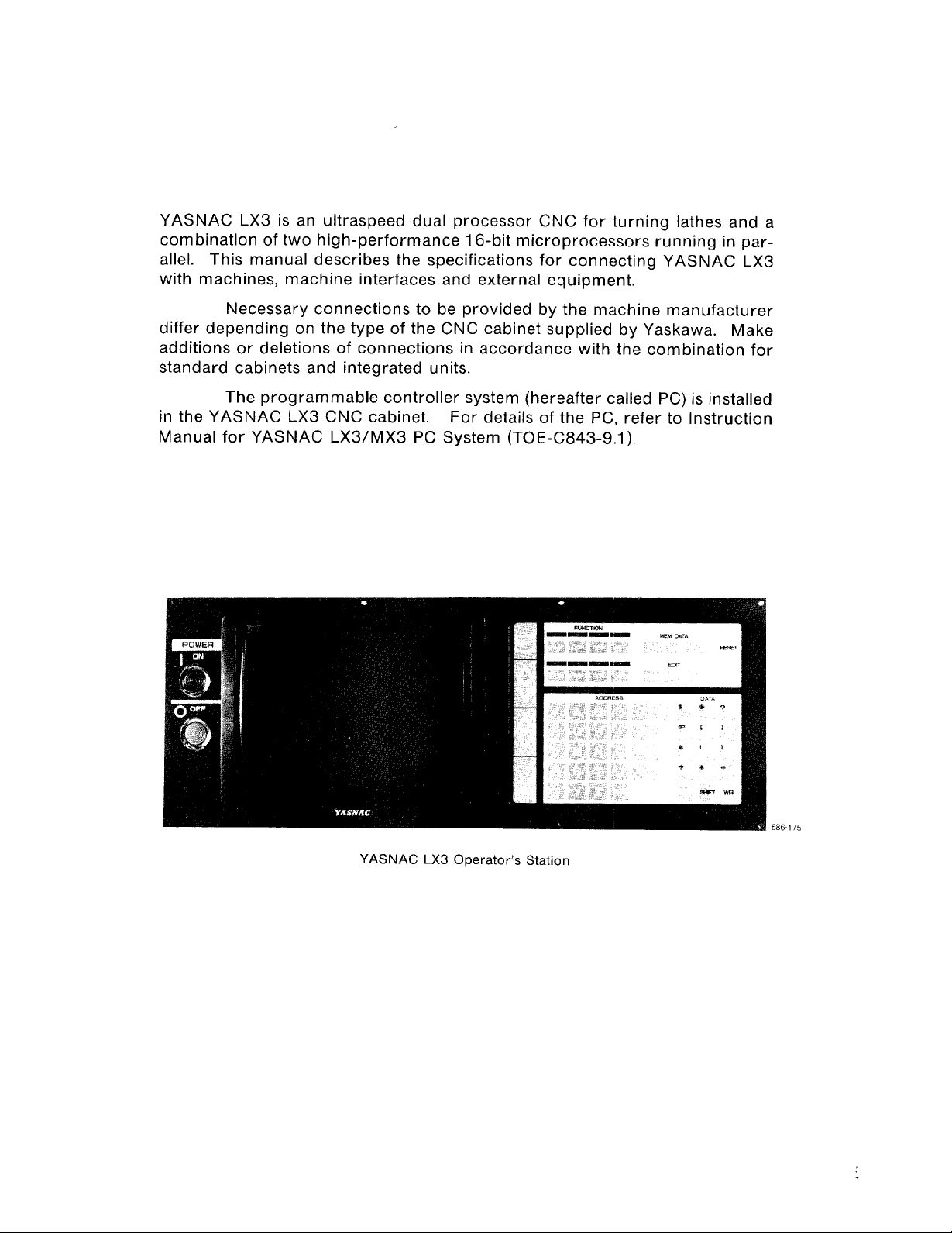
YASNAC LX3 Operator’s Station
586175
Page 4
CONTENTS
1. CONFIGURATION
1.1 SYSTEM CONFIGURATION
1.2 STANDARD CABINETS AND INTEGRATED UNITS
................... . . . .......... . . . ...... . . . . . . . .......... . . ..... . . . . .
. . . . . . . . . . . . . . . . . . . . . . . . . . . . . . . . . . . . . . . . . . . . . . . . . . . . . . . . . . . . .
. . . . . . . . . . . . . . . . . . . . . . . . . . . . . . . . . . . . . .
Page
2. Environmental coNDITloNs" """"" """""""""'"""""""""""""""""""""""""""""""""""""" 1
3. CABINET CONSTRUCTION DESIGN
4. CABINET DESIGN
4.1 SELECTION OF HEAT EXCHANGER
4.2 HEAT VALUES OF UNITS
FOR HEAT FACTORS
. . . . . . . . . . . . . . . . . . . . . . . . . . . . . . . . . . . . . . . . . . . . . . . . . . . . . . . . . . . . . .
...... . . . .......... . . ........... . . . ......... . . . . .
. . . . . . . . . . . . . . . . . . . . . . . . . . . . . . . . . . . . . . . . . . . .
. . . . . . . . . . . . . . . . . . . . . . . . . . . . . . . . . . . . . . . . . . . . . . . . . . .
5.cABLE ENTRANcE "". """"" """"" """"" ""`"" """"""""""""""""""""""""""`"""""""""""""""""" 4
5.1 LAYOUT OF CABLE CONNECTORS
5.2 CLAM PINGCABLES, AN DGROUNDING CAB LESHl ELD""S. """-."• ""C.""• """" O""O""""" 4
. . . . . . . . . . . . . . . . . . . . . . . . . . . . . . . . . . . . . . . . . . . . . . . . . . . .
6. CONNECTION DIAGRAMS O""""`• "O""""O"C... O".O""".• """""""• """"""""• O...OO""""OOOO"5
7. POwERSUPPLY Connection "O"""O"""""".".-.• """""".• O"""O"""""• "".. C"CC""""""""" 6
7.1 POWER SUPPLY CONNECTION TO CPU MODULE
7.2 POWER SUPPLY CONNECTION TO STANDARD CABINETS
8. CONNECTING POWER UNIT (TYPE CPS-1ON) AND PC BOARD
. . . . . . . . . . . . . . . . . . . . . . . . . . . . . . . . . . . . .
. . . . . . . . . . . . . . . . . . . . . . . . . . . .
(TYPE JANCD-PC20) TO CRT OPERATOR’S PANEL (CRT/P) ...sos.00.. . ...0..... 7
9. CONNECTION OF MANUAL PULSE GENERATOR (HPG) .00”.”.”0..”””o”””oo””””oo 8
10. CONNECTION OF INPUT SEQUENCE OO”.OO”””””” ””””” ””””” ”””.. ”””o”””o”o”””o o””” 8
10.1 CONNECTION
10.2 DETAl LSOFSIGNALS .O... O......• . . . . . . . . . . .. O"". """" ."""" "". ""S""....• ."""""".""""• 9
. . . . . . . . . . . . . . . . . . . . . . . . . . . . . . . . . . . . . . . . . . . . . . . . . . . . . . . . . . . . . . . . . . . . . . . .
1
1
1
1
3
3
3
4
6
6
8
ll. Connection TO FEED SERVO UNITS(SVX AND SVZ)O"OO"""OO.""CO."""""""""lo
12. CONNECTION TO SPINDLE DRIVE UNIT (SDU)
.. . . . . . . . . . . .. . . . . . . . . . . . . . . . . . . . .
13. CONNECTION TO SPINDLE PULSE GENERATOR (SPG)”” O””.”O””O”O”OS”.O.0””””13
14. CONNECTION TO RS-232C INTERFACE
14.1 CON NECTIONO . . .. 00 . . . . .. 000 . . . . . . . . .. O.. O... O"""" "O""" ."" O"". "" O"O.Ooo--oooo-o o---mm 13
14.2 RS-232C interface . .. O... O..................• ".. "". S."" O""" O"O""" O"" O"" SCS""O"O"""- 14
. . .. . . . . . . . . . . .. . . . . . . . . . . . . . . . . . . . . . . . . . .
15. DIREcT-lN slGNALcoNNEcTloN """""""""""""""""""""""""""""""""""""""`"""""""""lo
16. CONNECTION TO GENERAL-PURPOSE 1/0 SIGNALS
16.1 l/O PORTS
16.2 l/O CIRCUITS OF l/O PORTS
16.3 1/0 SIGNAL INTERFACE
17. CABLES
17.1 LIST OF CABLES
17.2 LIST OF CONNECTORS
17.3 SPECIFICATIONS OF CABLE
18. STANDARD 1/0 SIGNALS
18.1 LIST OF NC STAN DARDl/O SIGNALS . ..o . . . . . . . . . . . . . . . ..o . . . . . . . ..””.. o.””.”.”””””” 42
18.2 DETAILS OF SIGNALS . . . . . .. O........• . . . . .. O... O.""..."• """"."""• "OOOO""""C". "OOO""" 48
APPENDIX A DIMENSIONS in mm
APPENDIX B 1/0 PORT ADDRESS SETTING
APPENDIX C STANDARD WIRING COLORS OF YASNAC
. . . . . . . . . . . . . . . . . . . . . . . . . . . . . . . . . . . . . . . . . . . . . . . . . . . . . . . . . . . . . . . . . . . . . . . . . . . .
. . . . . . . . . . . . . . . . . . . . . . . . . . . . . . . . . . . . . . . . . . . . . . . . . . . . . . . . .
. . . . . . . . . . . . . . . . . . . . . . . . . . . . . . . . . . . . . . . . . . . . . . . . . . . . . . . . . . . . . .
. . . . . . . . . . . . .. . . . . . . . . . . . . . . . . . . . . . . .. . . . . . . . . . . . . . . . . . . . . . . . . . . . . . . . . . . . . . . . . .
. . . . . . . . . . . . . . . . . . . . . . . . . . . . . . . . . . . . . . . . . . . . . . . . . . . . . . . . . . . . . . . . . . . . .
. . . . . . . . . . . . . . . . . . . . . . . . . . . . . . . . . . . . . . . . . . . . . . . . . . . . . . . . . . . . . . .
. . . . . . . . . . . . . . . . . . . . . . . . . . . . . . . . . . . . . . . . . . . . . . . . . . . . . . . . . .
. . . . . . . . . . . . . . . . . . . . . . . . . . . . . . . . . . . . . . . . . . . . . . . . . . . . . . . . . . .
. . . . . . . . . . . . . . . . . . . . . . . . . . . . . . . . . . . . . . . . . . . . . . . . . . . . . . . . . .
. . . . . . . . . . . . . . . . . . . . . . . . . . . . . . . . . . . . . . . . . . . . . . . .
. . . . . . . . . . . . . . . . . . . . . . . . . . . . . . . . . . .
. . . . . . . . . . . . . . . . . . . . . . . . . . .
12
13
17
17
17
19
39
39
40
40
42
73
81
82
Page 5
Subject Chapter Section
A Alarm andlnput Error Outputs. . . . . . . . . . . . . . . . . . . . . . . . . . . . . . . . . . . . . . . .18 . . . . . .26. 5626 . . . ...56
Auxiliary Function Lock Input . . . . . . . . . . . . . . . . . . . . . . . . . . . . . . . . . . . . . . ..18 . . . . ..18. 2. 18 . . . ...55
c CABINET CONSTRUCTION DESIGN . . . . . . . . . . . . . . . . . . . . . . . . . . . . . . 3 . . . . . . . . . . . . . . . . . . . . 1
CABINET DESIGN FOR HEAT FACTORS . . . . . . . . . . . . . . . . . . . . . . . . . 4 . . . . . . . . . . . . . . . . . . . . 3
CABLE ENTRANCE . . . . . . . . . . . . . . . . . . . . . . . . . . . . . . . . . . . . . . . . . . . . 5 . . . . . . . . . . . . . . . ----- 4
CABLES . . . . . . . . . . . . . . . . . . . . . ..-. . . . . . . . . . . . . . . . . . . . ..-- . . . . ...17 . . . . . . . . . . . . . . . . . ...39
CLAMPING CABLES, AN D GROUNDING CABLE SHIELD . . . . . . . . . . . 5 . . . . . .5. 2 . . . . . . . . . . 4
Combined Fixed Cycle Cutting Override Inputs . . . . . . . . . . . . . . . . . . . . . . 18. . . . . . 18.2. 48 . . . ...71
CON FIG URATION . . . . . . . . . . . . . . . . . . . . . . . . . . . . . . . . . . . . . . . . . . . . . . . . 1 . . . . . . . . . . . . . . . . . . . . 1
CONNECTING POWER UNIT AND
PC BOARD TO CRT OPERATOR’S PANEL . . . . . . . . . . . . . . . . . . . . . . . . . . . 8 . . . . . . . . . . . . . . . . . . . . 7
Connection . . . . . . . . . . . . . . . . . . . . . . . . . . . . . . . . . . . . . . . . . . . . . . . . . ...10. . . . ..10.1 . . . . . . . . . 8
Connection . . . . . . . . . . . . . . . . . . . . . . . . . . . . . . . . . . . . . . . . . . . . . . . . . . . ...14.. . . ..14. 1 . . . . . . ...13
CONNECTION DIAGRAMS . . . . . . . . . . . . . . . . . . . . . . . . . . . . . . . . . . . . . . . . . 6 . . . . . . . . . . . . . . . . . . . . 5
CONNECTION OF INPUT SEQUENCE . . . . . . . . . . . ...-............10.. . . . . . . . . . . . . . . . . . . 8
CONNECTION OF MAN UAL PULSE GENERATOR . . . . . . . . . . . . . . . . . . . . 9 . . . . . . . . . . . . . . . . . . . . 8
CO,NNECTION TO FEED SERVO UNITS . . . . . . . . . . . . . . . . . . . . . . . ...11.... . . . . . . . . . . . . . ...10
CONNECTION TO GENERAL-PURPOSE l/O SIGNALS . . . . . . . . . . . . . ..16 . . . . . . . . . . ..- . . . . ...17
CON NECTION TO RS-232C INTERFACE. . . . . . . . . . . . . . . . . . . . . . . . . . ..14..... . . . . . . . . . . . . ...13
CON NECTION TO SPIN DLE DRIVE UN IT. -- . . . . . . . . . . . . . . . . . . . . . . . ..l2 . . . . . . . . . . . . . . . . . ...12
CON NECTION TO SPIN DLE PULSE GENERATOR . . . . . . . . . . . . . . . . . . ..l3 . . . . . . ..- . . . . . . . . ...13
CPU Module . . . . . . . . . . . . . . . . . . . . . . . . . . . . . . . . . . . . . . . . . . . . . . . . . . . . . . ..17......17.2.1 . . . ...40
CRT Operator’s Panel . . . . . . . . . . . . . . . . . . . . . . . . . . . . . . . . . . . . . . . . . . . ...17......17.2.2 . . . ...40
Current Value Storing Input . . . . . . . . . . . . . . . . . . . . . . . . . . . . . . . . . . . . . . .18 . . . . . .18. 2. 15- . . ...54
Page
DETAILS OF SIG NABS . . . . . . . . . . . . . . . . . . . . . . . . . . . . . . . . . . . . . . . . . . . . . . .10 . . . . . .10. 2 . . . . . . . . . 9
D
DETAILS OF SIG NABS . . . . . . . . . . . . . . . . . . . . . . . . . . . . . . . . . . . . . . . . . . . . . . . .18 . . . . . .18. 2 . . . . . . ...48
DIM ENSIONS in mm . . . . . . . . . . . . . . . . . . . . . . . . . . . . . . . . . . . . . . . . . . . . . . . .. APPEND Ix A . . . ...-..73
DIRECT-I N SIG NAL CONNECTION. . . . . . . . . . . . . . . . . . . . . . . . . . . . . . . . . ...15 . . . . . . . . . . . . . ...-...16
Display Reset inputs . . . . . . . . . . . . . . . . . . . . . . . . . . . . . . . . . . . . . . . . . . . - . . . . .18 . . . . . .18. 2. 33 . . . ...59
Dry Runlnput . . . . . . . . . . . . . . . . . . . . . . . . . . . . . . . . . . . . . . . . . . . . . . . . . . . .18 . . . . . .18. 2. 14 . . . ...54
Edit Lo~k . . . . . . . . . . . . . . . . . . . . . . . . . . . . . . . . . . . . . . . . . . . . . . . . . . . . . . . . . . . . .18 . . . . . .18. 2.17..... .55
E
Emergency Stop input . . . . . . . . . . . . . . . . . . . . . . . . . . . . . . . . . . . . . . . . . . . . --.10 . . . ...10.2.2 . . . . . . 9
Emergency Stop On Output . . . . . . . . . . . . . . . . . . . . . . . . . . . . . . . . . . . . . . . . .18 . . . . . .18. 2. 23 . . . ...56
End-of -program input, Rewind input : . . . . . . . . . . . . . . . . . . . . . . . . . . . . . .18 . . . . . .18. 2. 32 . . . ...58
ENVIRON MENTAL CON DITIONS . . . . . . . . . . . . . . . . . . . . . . . . . . . . . . . . . . . . . 2 . . . . . . . . . . . . . . . . . . . . 1
External Data lnputlnputs/Outputs . . . . . . . . . . . . . . . . . . . . . . . . . . . . . . . . .18 . . . . . .18. 2.45 . . . ...68
External Power On-Off Input . . . . . . . . . . . . . . . . . . . . . . . . . . . . . . . . . . . . . . . . ..10......10.2,3
External Reset lnputand Reset On Output . . . . . . . . . . . . . . . . . . . . . . . . . . . ..18 . . . . . .18. 2. 24 . . . ...56
External Store, Match, and Output Inputs . . . . . . . . . . . . . . . . . . . . . . . . . . . -- .18 . . . . . .18. 2. 34. -....59
External Work Number Search A Inputs . . . . . . . . . . . . . . . . . . . . . . . . . . . . . .18 . . . . . .18. 2. 40- . . ...52
F Feed Drive Unit . . . . . . . . . . . . . . . . . . . . . . . . . . . . . . . . . . . . . . . - . . . . . . . ..17..... .17. 2.3 . . . ...40
Feed Override/Manual Jogging Speed Selection Input . . . . . . . . . . . . . . ...18......18.2.7 . . . ...51
HEAT VALUES OF UN ITS...... . . . . . . . . . . . . . . . . . . . . . . . . . . . . . . . . . . . . 4 . . . . . .4. 2 . . . ..-- . . . 3
H
High-speed Rewind and Start input. . . . . . . . . . . . . . . . . . . . . . . . . . . . . . . . . . . .18 . . . . . .18. 2. 50- . . ...72
I lnputand Output for Control Operation Modes . . . . . . . . . . ...-.........18......18.2.2 . . . ...48
input Signals for Cycle Start, Stop Output Signals . . . . . . . . . . . . . . . . . . . ...18......18.2.1 . . . ...48
interlock input . . . . . . . . . . . . . . . . . . . . . . . . . . . . . . . . . . . . . . . . . . . . . . . . . . . . ..18 . . . . . .18. 2. 25 . ...-.56
Interruption Point Return Input... . . . . . . . . . . . . . . . . . . . . . . . . . . . . . . . . -..18......18,2.20...-..55
1020 Boards . . . . . . . . . . . . . . . . . . . . . . . . . . . . . . . . . . . . . . . . . . . . . . . . . . ...16......16.3.1 . . . ...19
l/O Board Type JANCD-1020 . . . . . . . . . . . . . . . . . . . . . . . . . . ...-........16. . . ...16.2.1 . . . ...17
l/O Board Type JANCD-SP 20.... . . . . . . . . . . . . . . . . . . . . . . . . . . . . . . . . . . .16 . . . ...16.2.2 . . . ...18
l/O CIRCUITS OFl/O PORTS.... . . . . . . . . . . . . . . . . . . ...-..........16. . . ...16.2 . . . . . ...17
l/O PORT ADDRESS SETTING . . . . . . . ..- . . . . . . . . . . . . . . . . . . . . . . . . . . . . .. APPENDIX B. . . . . . . ...81
l/O PORTS . . . . . . . . . . . . . . . . . . . . . . . . . . . . . . . . . . . . . . . . . . . . . . . . . . . . . . . ...-16.. . . ..16. 1 . . . . . . ...17
l/O SIGNAL INTERFACE . . . . . . . . . . . . . . . . . . . . . . . . . . . . . . . . . . . . . . . . . . . ..16 . . . . ..16.3 . . . . . . . ..l9
. . . . . .
9
...
111
Page 6
INDEX (Cent’d)
Subject
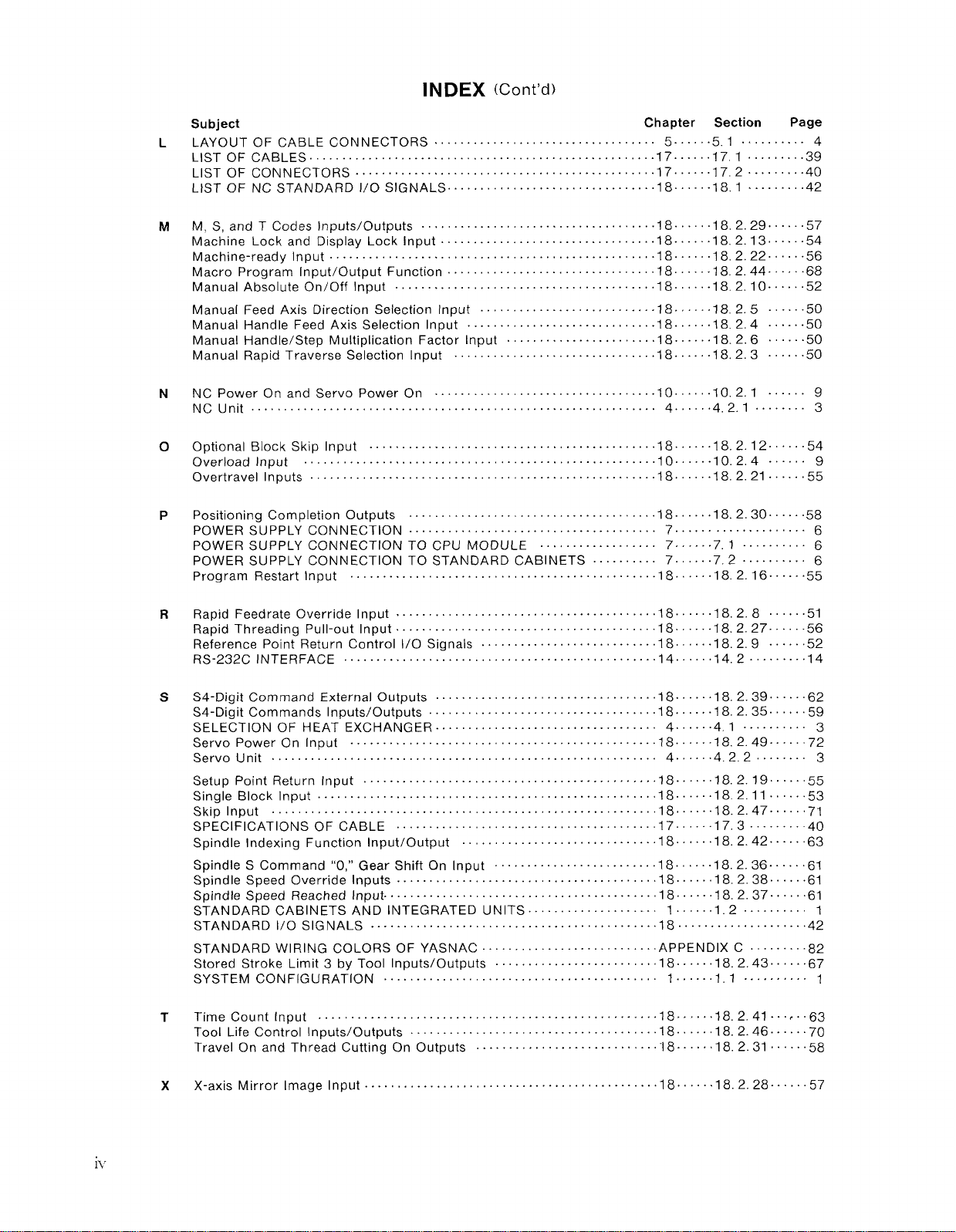
LAYOUT OF CAB LE CONNECTORS . . . . . . . . . . . . . . . 5. ..5.1 . . . . . 4
L
LIST OF CABLES . . . . . . . . . . . . . . . . . . . . . . . . . . . . . . . . . . . . . . . . . . . . .17 . . . . 17.1 . . . . . ...39
LIST OF CON NECTARS . . . . . . . . . . . . . . . . . . . . . . . . . . . . . . . . . .17 . . . . 17.2 . . . ...40
LIST OF NC STAN DAR D1/O SIGNALS. . . . . . . . . . . . . . . . . . . . . . ...18. . . 18.1 . . . ...42
M, S,and TCodeslnputs/Outputs . . . . . . . . . . . . . . . . . . . . . . . . . . . .18. . . 18.2.29 . . ...57
M
Machine Lock and Display Lock Input . . . . . . . . . . . . . . . . . . . . . . . . . . 18. . . . . 18.2. 13....54
Machine-ready input . . . . . . . . . . . . . . . . . . . . . . . . . . . . . . . . . . . . 18... 18. 2.22....56
Macro Program Input/Output Function . . . . . . . . . . . . . . . . . . . . . ...18 . . . . 18.2 .44...68
Manual Absolute On/Off Input . . . . . . . . . . . . . . . . . . . . . . . . . . . . . . . . 18.. . 18. 2.10 . . ...52
Manual Feed Axis Direction Selection Input . . . . . . . . . . . . . . . ...-18. 18.2.5 . . . ...50
Manual Handle Feed Axis Selection Input . . . . . . . . . . . . . . . . . . . ...18.. .18 .2.4 . . . ...50
Manual Handle/Step Multiplication Factor Input . . . . . . . . . . . . . ...18....18. 2.6 . . . ...50
Manual Rapid Traverse Selection Input . . . . . . . . . . . . . . . . . . . . . . . ...18. . ..18.2.3 . . ...50
N
NC Power Onand Servo Power On . . . . . . . . . . . . . . . . . . . . . . . . . . . .10...10.2.1 . . . . . . 9
NCUnit................... . . . . . . . . . . . . . . . . . . . . . . . . . . . . . . 4. . . 4.2.1..... 3
Optional Block Skip Input . . . . . . . . . . . . . . . . . . . . . . . . . . . . . . . . . . .18. . . 18 .2.12..54
o
Overload Input . . . . . . . . . . . . . . . . . . . . . . . . . . . . . . . . . . - . . . . . . 10.. .10.2. 4 . . . 9
Overtravel inputs . . . . . . . . . . . . . . . . . . . . . . . . . . . . . . . . . . . . . . . . . . . .18. 18. 2.21 . . ...55
Positioning Completion Outputs . . . . . . . . . . . . . . . . . . . . . . . . . . 18. . . . . . 18.2.30 . . ...58
P
POWER SUPPLY CONNECTION.. . . . . . . . . . . . . . . . . . . . . . . . . 7 . . . . . . . . . . . . . . . . 6
POWER SUPPLY CO NNECTIONTO CPU MODULE . . . . . . . . . . . . . 7, .7.1 . . . . . . 6
POWER SUPPLY CONNECTION TO STANDARD CABINETS . . . . . . . . . . 7. ..7.2 . . . . . . . . 6
Program Restart Input . . . . . . . . . . . . . . . . . . . . . . . . . . . . . . . . . . . . . . ...18..18.2.16. . . ...55
Chapter Section
Page
R
Rapid Feedrate Override input. . . . . . . . . . . . . . . . . . . . . . . . . . . ...18......18.2.8 . . ...51
Rapid Thread ing Pull-out input.. . . . . . . . . . . . . . . . . . . . . . . . . . . . . 18. . . . . . 18.2. 27..56
Reference Point Return Control l/O Signals . . . . . . . . . . . . . . . . . . . . . ...18 . ..18.2.9 . ...52
RS-232C INTERFACE . . . . . . . . . . . . . . . . . . . . . . . . . . . . . . . . . . . .1414 .2....... 14
S4-Digit Comma ndExterna10utputs . . . . . . . . . . . . . . . . . . . . . . . . . . . . .18 . . . . . .18. 2. 39....62
s
S4-Digit Commands inputs/Outputs . . . . . . . . . . . . . . . . . . . . . . . . .18. . . 18.2 .35....59
SELECTION OF HEAT EXCHANGER. . . . . . . . . . . . . . . . . . . . . . 4 . ...4.1 . . . . . . 3
Servo Power On Input
Servo Unit . . . . . . . . . . . . . . . . . . . . . . . . . . . . . . . . . . . . . . . . . . . . . . . . . . 4. . 4.2.2.... 3
Setup Point Return Input . . . . . . . . . . . . . . . . . . . . . . . . . . . . . . . . . . 18 . . .18. 2.19...55
Single Block input . . . . . . . . . . . . . . . . . . . . . . . . . . . . . . . . . . . . . . . . . 18. . . . . 18.2.11.53
Skip Input . . . . . . . . . . . . . . . . . . . . . . . . . . . . . . . . . . . . . . . . . . . . ...18...18. 2.47..71
SPECIFICATIONS OF CABLE . . . . . . . . . . . . . . . . . . . . . . . . . . . 17.17 . 3. . . . ...40
Spindle indexing Function input/Output . . . . . . . . . . . . . . . . . . . ...18 . ..18.2 .42.” ”.63
Spindle SCommand’’O,’’ Gear Shift On Input . . . . . . . . . . . . . . ...18.18. 2.36...61
Spindle Speed Override Inputs. . . . . . . . . . . . . . . . . . . . . . . . . . . . . . . . . . . 18. . . . . . 18. 2. 38 . . . ...61
Spindle Speed Reached input,... . . . . . . . . . . . . . . . . . . . . . . . . . . . . . . 18. . . . 18. 2.37 . ...61
STAN DARDCABIN ETS AN D INTEGRATED UN ITS . . . . . . . . . . . . . . . 1 . . . 1. 2. . . . . . . . . 1
STAN DARD1/O SIG NABS . . . . . . . . . . . . . . . . . . . . . . . . . . ...18 . . . . . . . . . . . . . ...42
STAN DARDWIRING COLORS OF YASNAC .................APPENDIX C.....82
Stored Stroke Limit 3by Tool inputs/Outputs . . . . . . . . . . . . . . . ...18......18. 2.43.....67
SYSTEM CONFIGURATION . . . . . . . . . . . . . . . . . . . . . . . . . . . . . . . . . . 1 . . . ...1.1 . . . . . 1
Time Count fnput . . . . . . . . . . . . . . . . . . . . . . . . . . . . . . . . . . . . . . . . . . .18.18.2. 41...,..63
T
Tool Life Control Inputs/Outputs . . . . . . . . . . . . . . . . . . . . . . . . . . . . . . . . 18... 18. 2.46 . . ...70
Travel Onand Thread Cutting On Outputs . . . . . . . . . . . . ..- . . . . . . . . ..” 18.. . . . 18.2 .31 . . ...58
. . . . . . . . . . . . . . . . . . . . . . . . . . . . . . . . . . . . . . . . . . .
18....18.2.49....72
x
X-axis Mirror lmagelnput . . . . . . . . . . . . . . . . . . . . . . . . . . . . . . . . . . . . . 18. . . . 18.2.28 . . . ...57
Page 7
1. CONFIGURATION
3. CABINET CONSTRUCTION DESIGN
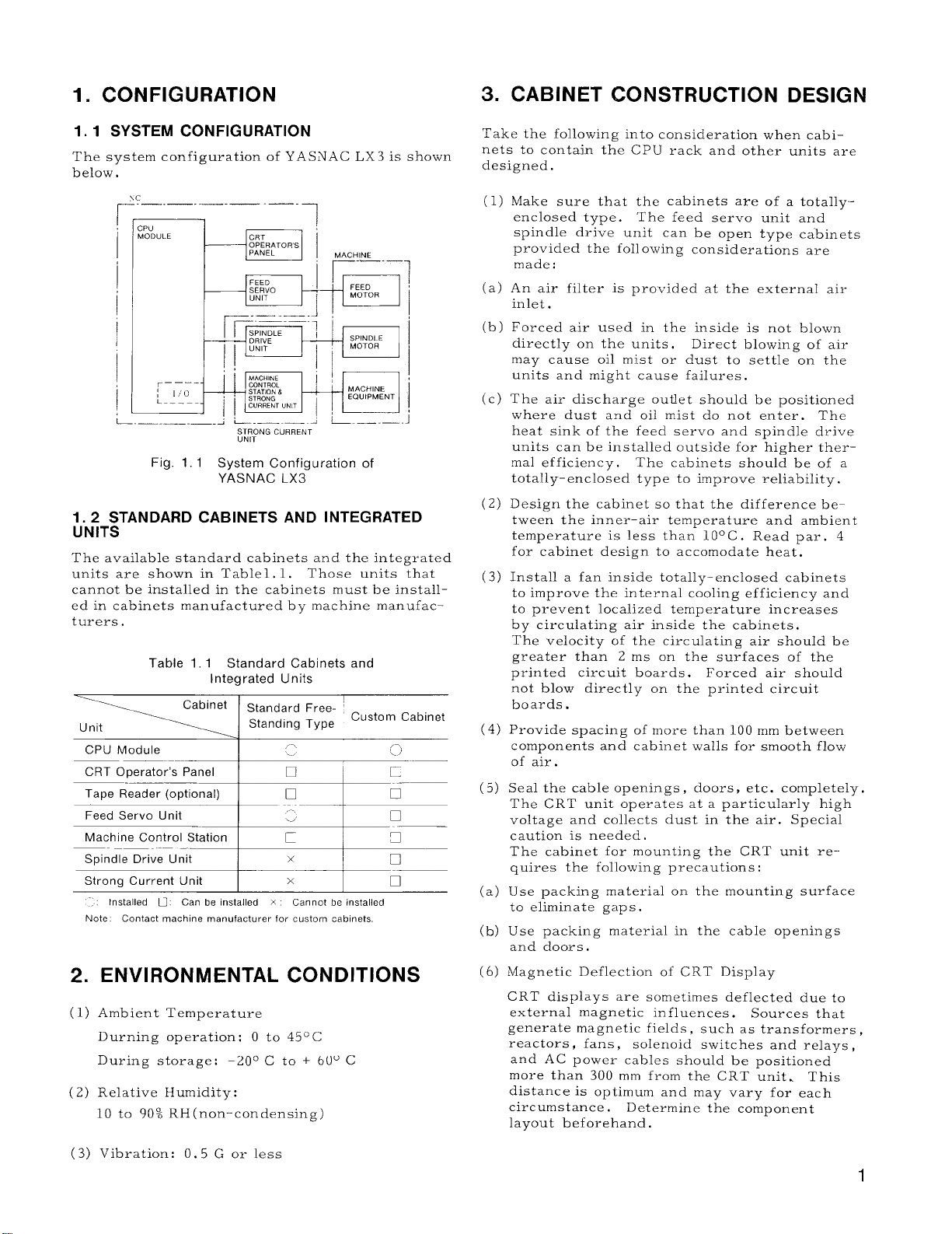
1.1 SYSTEM CONFIGURATION
The system configuration of YASNAC LX3 is shown
below.
&? —._._.
I
CPU
MODULE
Fig. 1.1 System Configuration of
—.— .=
I
YASNAC LX3
fiN;T:TANDARD CABINETS AND INTEGRATED
The available standard cabinets and the integrated
units are shown in Tablel, 1,
cannot be installed in the cabinets must be install–
ed in cabinets manufactured by machine manufac–
turers.
Table 1.1 Standard Cabinets and
Unit
CPU Module
CRT Operator’s Panel
Tape Reader (optional)
Feed Servo Unit
Spindle Drive Unit
“’’=’’O’s’-=
Strong Current Unit
Installed U. Can be installed X Cannot be installed
Note
Contact machine manufacturer for custom cabinets
ENVIRONMENTAL
2.
Ambient Temperature
(1)
Durning operation: O to
During storage:
Relative Humidity:
(2)
10 to 90% RH(non-condensing)
Integrated Units
Cabinet
Standard Free-
Standing Type
In
–20° C to + 60” C
Those units that
Custom Cabinet
-, ,x
.–.
❑ 1
I
x
CONDITIONS
45° C
‘<~
r
❑
❑
Take the following into consideration when cabinets to contain the CPU rack and other units are
designed.
(1)
Make sure that the cabinets are of a totallY-
enclosed type.
spindle drive unit can be open type cabinets
provided the foil owing considerations are
made:
(a)
An air filter is provided at the external air
inlet.
Forced air used in the inside is not blown
(b)
directly on the units, Direct blowing of air
may cause oil mist or dust to settle on the
units and might cause failures.
The air discharge outlet should be positioned
(c)
where dust and oil mist do not enter.
heat sink of the feed servo and spindle drive
units can be installed outside for higher ther–
ma] efficiency. The cabinets should be of a
totally-enclosed type to improve reliability.
(2)
Design the cabinet so that the difference between the inner-air temperature and ambient
temperature is less than 10° C . Read par. 4
for cabinet design to accommodate heat.
Install a fan inside totally-enclosed cabinets
(3)
to improve the internal cooling efficiency and
to prevent localized temperature increases
by circulating air inside the cabinets.
The velocity of the circulating air should be
greater than 2 ms on the surfaces of the
printed circuit boards. Forced air should
not blow directly on the printed circuit
boards.
Provide spacing of more than 100 mm between
(4)
components and cabinet walls for smooth flow
of air.
Seal the cable openings , doors, etc. completely,
(5)
The CRT unit operates at a particularly high
voltage and collects dust in the air. Special
caution is needed.
The cabinet for mounting the CRT unit requires the fol[owing precautions:
Use packing material on the mounting surface
(a)
to eliminate gaps.
Use packing material in the cable openings
(b)
and doors,
Magnetic Deflection of CRT Display
(6)
CRT displays are sometimes deflected due to
external magnetic influences . Sources that
generate magnetic fields , such as transformers ,
reactors, fans,
and AC power cables should be positioned
more than 300 mm from the CRT unit. This
distance is optimum and may vary for each
circumstance. Determine the component
layout beforehand.
The feed servo unit and
The
solenoid switches and relays ,
Vibration: O. 5 G or less
(3)
1
Page 8
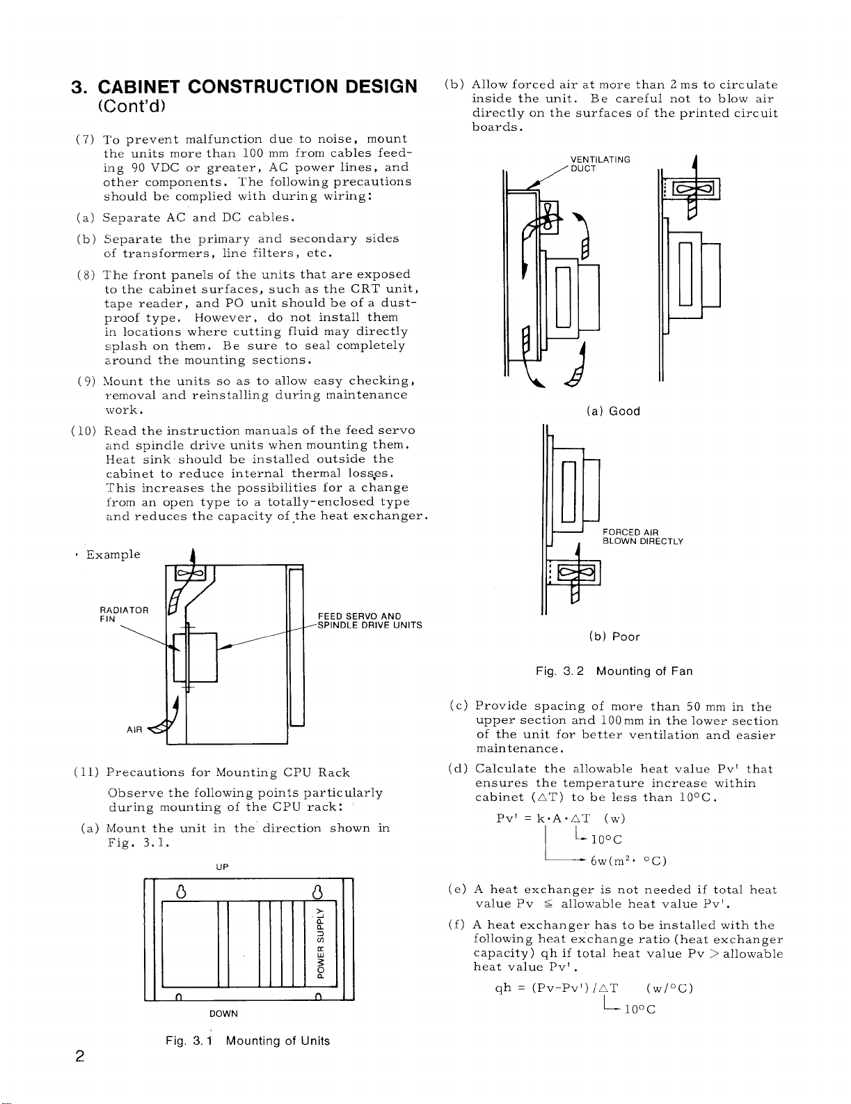
3. CAB
((Jon
(7)
(a)
(b)
(8)
(9)
(lo)
. Example
NET CONSTRUCTION DESIGN
[’d)
TO prevent malfunction due to noise, mount
the units more than 100 mm from cables feedi:og 90 VDC or greater, AC power lines, and
other components.
should be complied with during wiring:
Separate AC and DC cables.
Separate the primary and secondary sides
of transformers, line filters, etc.
The front panels of the units that are exposed
to the cabinet surfaces, such as the CRT unit,
tape reader, and PO unit should be of a dustproof type. However, do not install them
in locations where cutting fluid may directly
splash on them.
z.round the mounting sections.
hlount the units so as to allow easy checking,
removal and reinstalling during maintenance
work.
Read the instruction manuals of the feed servo
and spindle drive units when mounting them.
Heat sink should be installed outside the
c:abinet to reduce internal thermal loss-es.
This increases the possibilities for a change
from an open type to a totally-enclosed type
and reduces the capacity of the heat exchanger.
A
The following precautions
B e sure to seal completely
(b) Allow forced air at more than 2 ms to circulate
inside the unit,
directly on the surfaces of the printed circuit
boards.
Be careful not to blow air
VENTILA1
/ DUCT
“ING
—
—
l--
(a) Good
FORCED AIR
P
BLOWN DIRECT
LY
R14D
FIN
I I
I
l?recautions for Mounting CPU Rack
(11)
Observe the following points particularly
during mounting of the CPU rack:
Mount the unit in the direction shown in
(a)
Fig. 3.1.
UP
n
DOWN
FEED SERVO AND
SPINDLE DRIVE UNITS
n
*
(b) Poor
Fig. 3.2 Mounting of Fan
(c) Provide spacing of more than 50 mm in the
upper sec~ion and 100 mm in the lower section
of the unit for better ventilation and easier
maintenance.
Calculate the allowable heat value Pv’ that
(d)
ensures the temperature increase within
cabinet (AT) to be less than 10° C.
pvf =k. A.~T (W)
L
10”C
L
A heat exchanger is not needed if total heat
(e)
value Pv s allowable heat value Pv’ .
(f)
A heat exchanger has to be installed with the
following heat exchange ratio (heat exchanger
capacity) qh if total heat value Pv > allowable
heat value Pv’ .
qh = (pv-pv[) /AT
6w(m2. ‘C)
L-
10”C
(w/”c)
Fig. 3.1 Mounting of Units
2
Page 9
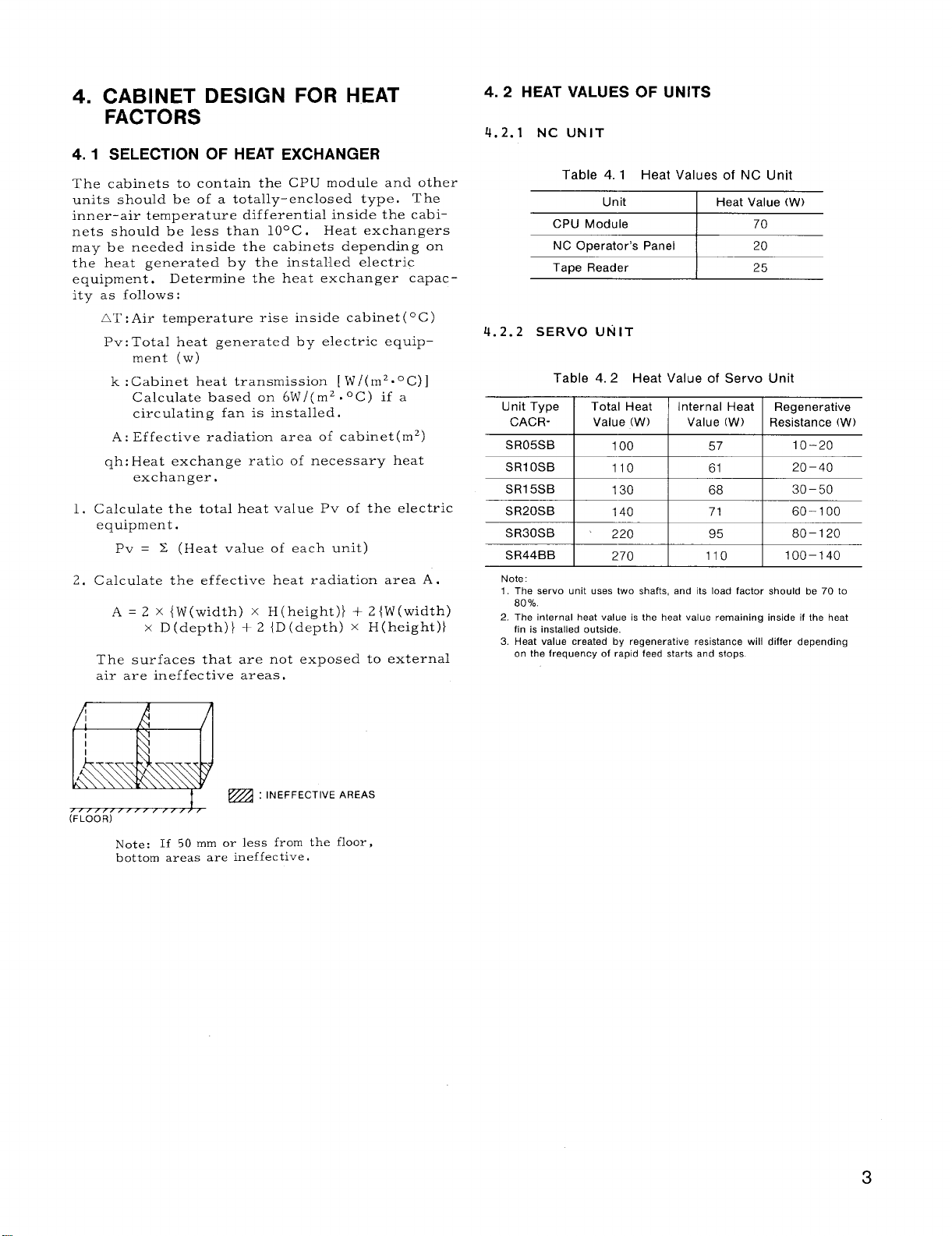
4. CABINET DESIGN FOR HEAT
FACTORS
4.1 SELECTION OF HEAT EXCHANGER
The cabinets to contain the CPU module and other
units should be of a totally–enclosed type. The
inner-air temperature differential inside the cabi–
nets should be less than 10° C.
may be needed inside the cabinets depending on
the heat generated by the installed electric
equipment.
Determine the heat exchanger capac-
ity as follows:
AT :Air temperature rise inside cabinet
Pv: Total heat generated by electric equip-
ment (w)
k :Cabinet heat transmission [ W/(m2.0C)]
Calculate based on 6W/(m2 .°C) if a
circulating fan is installed.
A : Effective radiation area of cabinet
qh: Heat exchange ratio of necessary heat
exchanger.
1. Calculate the total heat value Pv of the electric
equipment.
Pv = X (Heat value of each unit)
2. Calculate the effective heat radiation area A .
A = 2 x {W(width)
x D(depth)} + 2 {D (depth) x H(height)}
x H(height)} + 2 {W(width)
The surfaces that are not exposed to external
air are ineffective areas.
Heat exchangers
4.2 HEAT VALUES OF UNITS
4.2.1 NC UNIT
Table 4.1 Heat Values of NC Unit
Unit
CPU Module
NC Operator’s Panel
Tape Reader 25
4. 2.2 SERVO UNIT
Table 4.2 Heat Value of Servo Unit
Unit Type Total Heat Internal Heat
CACR- Value (W) Value (W)
SR05SB
SR1OSB I
SR30SB ‘
SR44BB
Note:
1. The servo unit uses two shafts, and its load factor should be 70 to
80%.
2. The internal heat value is the heat value remaining inside if the heat
fin is installed outside.
3. Heat value created by regenerative resistance will differ depending
on the frequency of rapid feed starts and stops.
100 57
110
I
220
270
Heat Value (W)
I
I
61
95
110
70
20
Regenerative
Resistance (W)
10–20
I 20-40
80–120
100–140
~ : INEFFECTIVE AREAS
(FLOOR)
Note: If 50 mm or less from the floor,
bottom areas are ineffective.
3
Page 10
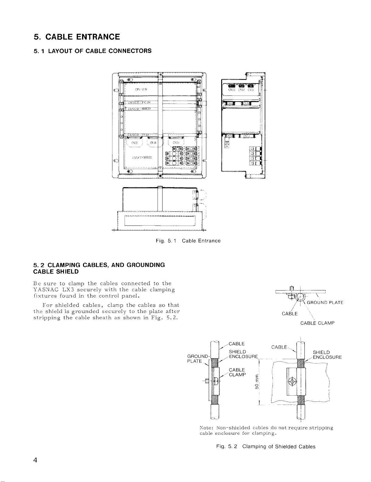
5. CABLE ENTRANCE
5.1 LAYOUT OF CABLE CONNECTORS
r d-
Fig. 5.1 Cable Entrance
5.2 CLAMPING CABLES, AND GROUNDING
CABI.E SHIELD
Be sure to clamp the cables connected to the
\’.4SNAC LX3 securely with the cable clamping
fixtures found in the control panel.
For shielded cables, clamp the cables so that
the shield is grounded securely to the plate after
stripping the cable sheath as sho~vn in Fig. 5.2.
GROU
PLATE
CABLE
SHIELD
ENCLOSURE
CABLE
CLAMP ~
I
~
\
GROUND PLATE
/
,/’
CABLE
CABLE CLAMP
-1
E
0
m
I
URE
Sote: Non-shielded cables do not require stripping
cable enclosure for clamping.
Fig. 5, 2 Clamping of Shielded Cables
Page 11
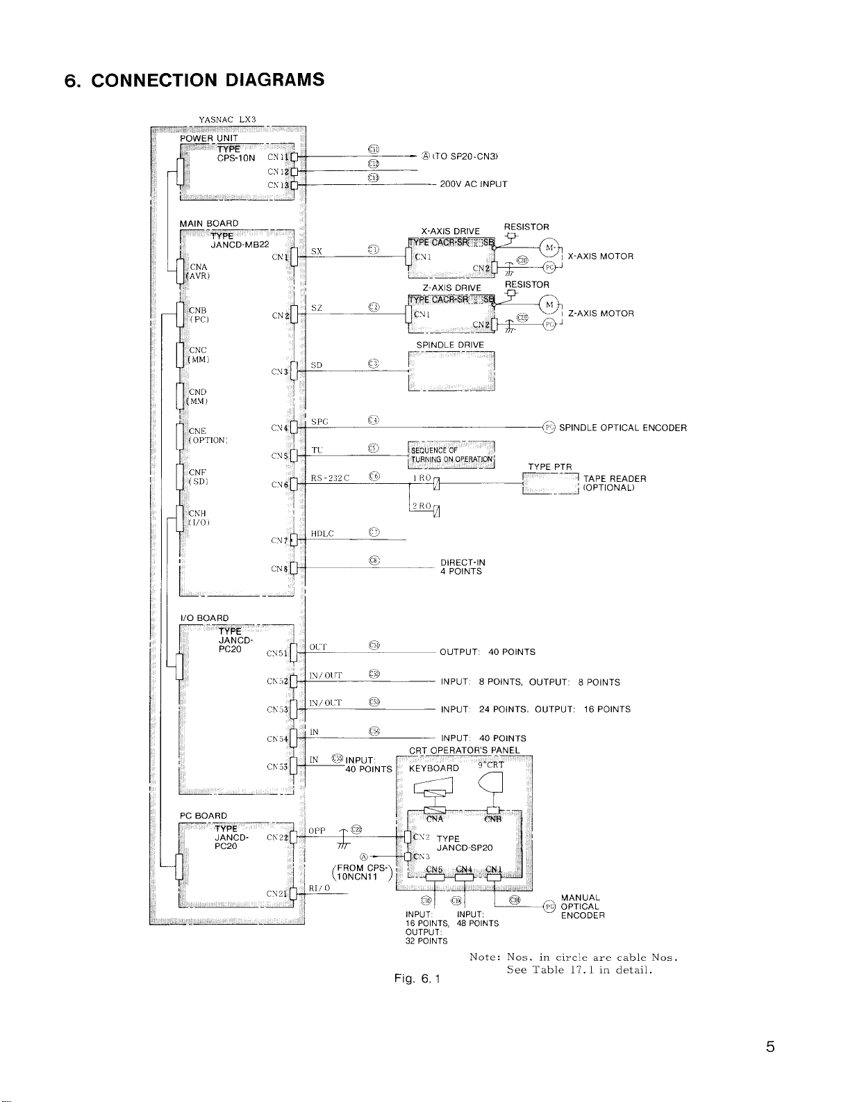
6. CONNECTION DIAGRAMS
X-AXIS MOTOR
Z-AXIS MOTOR
~@ SPINDLE OPTICAL ENCODER
TYPE PTR
~–-1 TAPE READER
‘L. _~ ‘oPTloNAL1
@
DIRECT-IN
4 POINTS
cable Nos.
detail.
5
Page 12
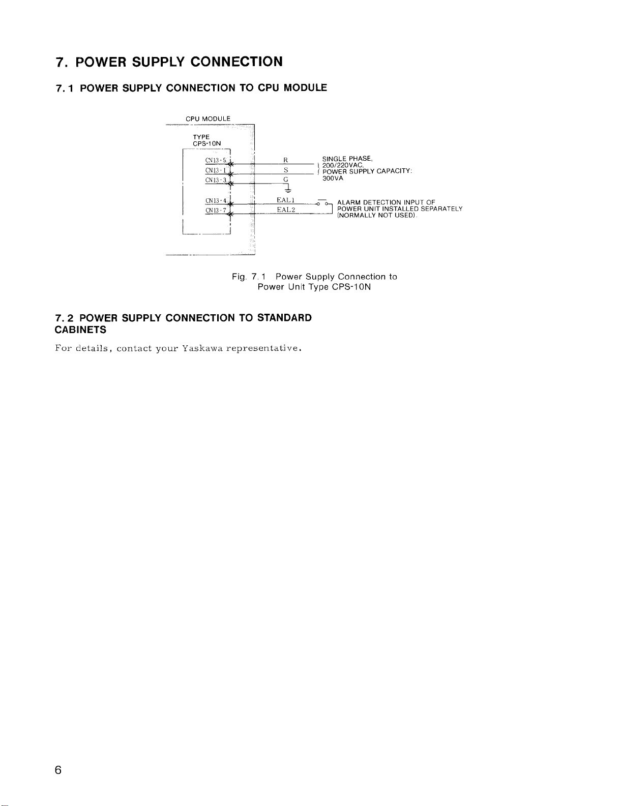
F)OWER SUPPLY CONNECTION
7.
7.1
POWER SUPPLY CONNECTION TO CPU MODULE
CPU MODULE
—.
TYPE
CPS-1 ON
—— .
[Sk
L_:-’:’:;’:’’’’’uTOF
——
Fig. 7.1 Power Supply Connection to
Power Unit Type CPS-I ON
POWER SUPPLY CONNECTION TO STANDARD
7.2
CABINETS
For details, contact your Yaskawa representative,
R
s
G
—
SINGLE PHASE,
I 200/220VAC,
( ~~o~~fl SUPPLY CAPACITY:
POWER UNIT INSTALLED SEPARATELY
Page 13
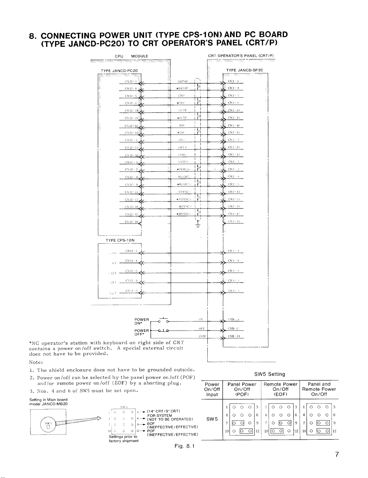
8. CONNECTING POWER UNIT (TYPE CPS-I ONI AND PC BOARD
(TYPE JANCD-PC20) TO CRT OPERATOR’S PANEL (CRT/P)
I
TYPE CPS-1ON
*NC operators station with keyboard on right side of CRT
contains a power on /off switch. .4 special external circuit
does not have to be provided.
Note:
1. The shield enclosure does not have to be grounded outside.
2. Power on/off can be selected
and/or
3. Nos. 4 and 6 of Sh’5 must be set open.
Setiing in Main board
model JANCD-MB20
remote power on/off (EOF) by a shorting plug.
by the panel power on/off (POF)
i!i
! ‘L-..—
L–_—–-
Power
On/Off
Input
Sw 5
Panel Power
On/Off
(POF)
—.—
SW5 Setting
Remote Power
On/Off
(EOF)
10003 1000:1
40006
70~9 70~9
lo~o12 loo~12
n❑
Remote Power
40006
Panel and
On/Off
Fig. 8, 1
7
Page 14
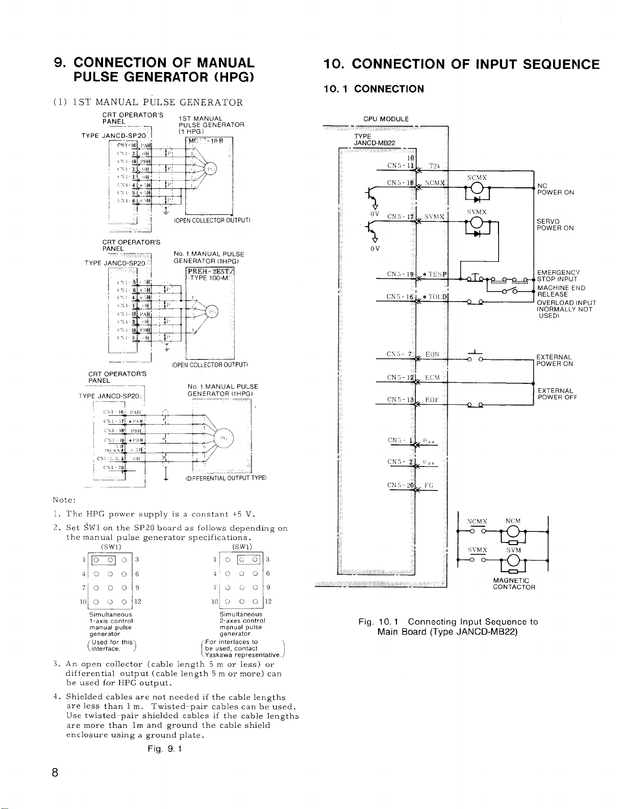
9.
CONNECTION OF MANUAL
PULSE GENERATOR (HPG)
(1)
1ST MANUAL PULSE GENERATOR
TYPE
10. CONNECTION OF INPUT SEQUENCE
10.1 CONNECTION
—.
CPU MODULE
-————1
NC
POWER ON
——+4
(OPEN COLLECTOR OUTPUT)
CRT OPERATOR’S
PANEL
—.— .-
TYPE JANCD-SP20
I
I
I
,.
:
,*
—1
1
! -,@,
!,,, !,
——.—
CRTOPERATOR’S
PANEL
“rYPE JAN CD-SP20.
,. —.
:p ~
Note:
1.
The HPG power supply is a constant +5 V.
?
Set ~ltil on the SP20 boardas follo~vs depending on
-.
the manual pulse generatol- specifications.
(Swl) (Swl)
No 1 MANUAL PULSE
GENERAToR (lHPG)
[OPEN COLLECTOR OUTPUT)
,-
,,
,,
I
‘M
I
No 1 MANUAL PULSE
GENERATOR (lHPG)
—.— --–, ,
1
,,,
,,
,.
(DIFFERENTIAL OUTPUT TYPEI
1
CN3-19 *1’Esp
~+
CN5- 16’ *TOLD
“4
II
-~++
CN3-IZ
CN5 -13
CN3- I
2“ ‘4 ‘
Lc\i
Eot
&
NCh4X
—
s\klx
—
NCbl
SVhl
i~=l
MAGNETIC
CONTACTOR
SERVO
POWER ON
EM ERG ENC’/
STOP INPUT
MACHINE E14D
RELEASE
OVERLOAD INPUT
(NORMALLY NOT
USED)
EXTERNAL
POWER ON
EXTERNAL
POWER OFF
1“M12 ‘~=412
Simultaneous
l-axIs control 2-axes control
manual pulse
generator generator
(:?:::::. th’s)
An open collector (cable length 5 m or less) or
3,
differential output (cable length 5 m or more) can
be used for HPG output.
Shielded cables are not needed if the cable lengths
4.
are less than 1 m.
Use twisted-pair shielded cables if the cable lengths
are more than lm and ground the cable shield
enclosure using a ground plate.
Twisted-pair cables can be used.
Simultaneous
manual pulse
For Interfaces to
be used, contact
(
Yaskawa representative 1
Fig. 9.1
8
Fig. 10.1 Connecting Input Sequence to
Main Board (Type JAN CD-MB22)
Page 15
10.2 DETAILS OF SIGNALS
10.2.1 NC POWER ON (NCMX) AND SERVO
POWER ON (SVMX)
(1) NCMX: This output is turned on when the
logic circuit of the control is energized.
(2) SVMX: This output is turned on when the
servo unit is energized.
unit, turn on the power supply when this signal
is outputted.
(3) The power supply turning on sequence is as
follows :
Close the power supply main switch for the
(a)
con.t~ol.
Either push the POWER ON button on the NC
(b)
operator’s station * or close the circuit between
EON and ECM. Then,
the servo control circuit are both energized,
and the circuit between NCMX (NC power
input and output) is closed.
With an external servo unit, design the
the servo control circuit power input
sequence so that the circuit is ener–
gized at the output of NCMX signals.
[
Again make the same power switching (pushing
(c)
the POWER ON button or closing the circuit
between EON and ECM) . Now, the servo power
supply is turned on, and the circuit between
SVMX (servo power input and output) is closed.
With an external servo unit, design
the servo power circuit power input
sequence so that the circuit is energized at the output of SVMX signals.
[
When the external circuit is ready after the
(d)
circuit between SVMX is closed, and the control
becomes ready, close the MRD (machine ready)
input of the 1/0 module. Then, RDY is dis–
played on the CRT, and operation becomes
possible.
With an external servo
the logic circuit and
1
1
10.2.2 EMERGENCY STOP(TESP) INPUT
When the circuit between emergency stop input
terminals (TESP ) is open , the control stops totally ,
the servo power supply is turned off, and the
emergency stop output (* ESPS) of general purpose
1/0 module is opened.
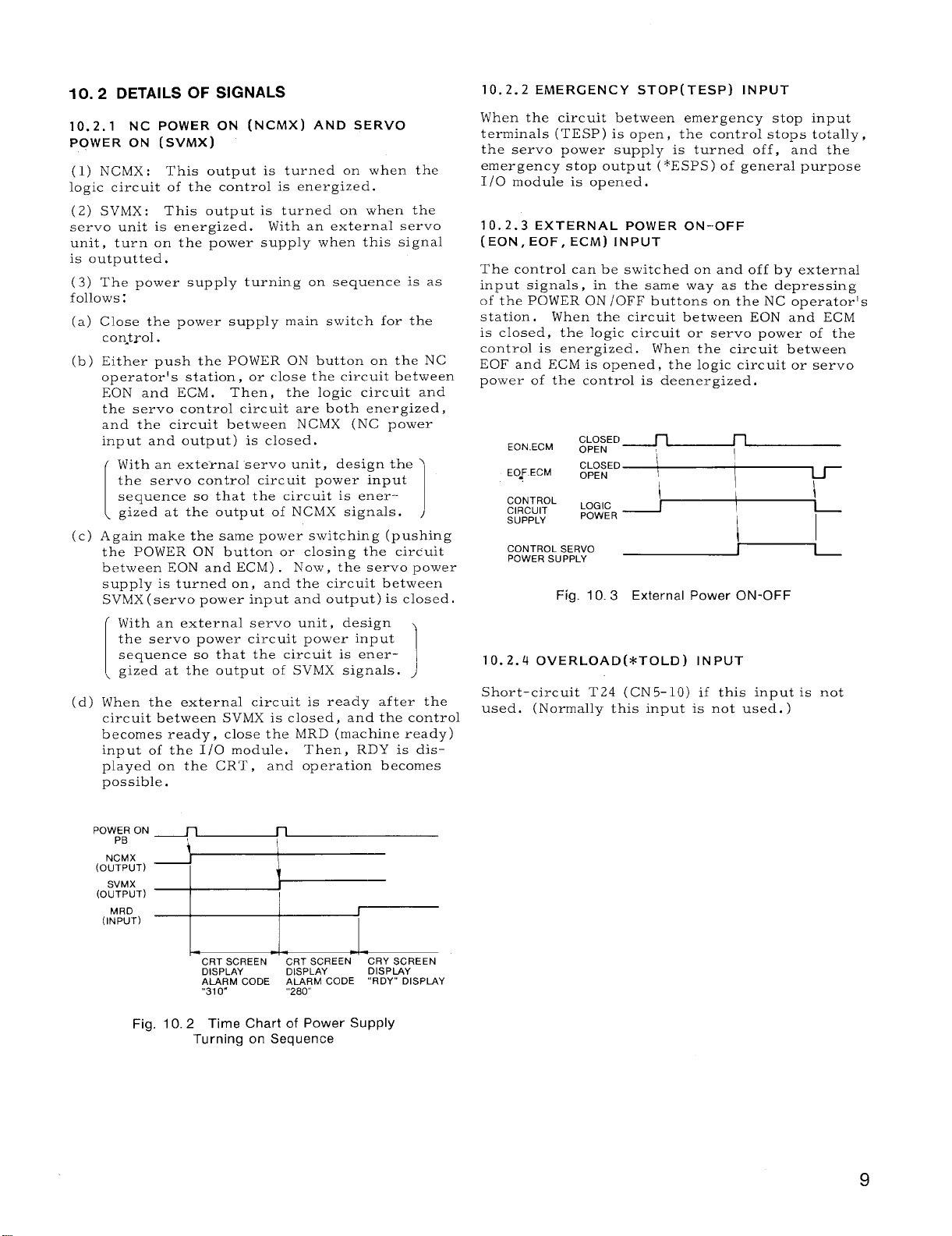
10. 2.3 EXTERNAL POWER ON-OFF
(EON, EOF, ECM) INPUT
The control can be switched on and off by external
input signals , in the same way as the depressing
of the POWER ON /OFF buttons on the NC operator’s
station . When the circuit between EON and ECM
is closed, the logic circuit or servo power of the
control is energized.
When the circuit between
EOF and ECM is opened, the logic circuit or servo
power of the control is deenergized.
EO-F.ECM
CONTROL
CIRCUIT
SUPPLY
CONTROL SERVO
POWER SUPPLY
Fig. 10.3
CLOSED
OPEN
LOG [C
POWER
1,
1
External Power ON-OFF
,
1
10.2.4 OVERLOAD (*TOLD) INPUT
Short-circuit T24 (CN 5- 10) if this input is not
used. (Normally this input is not used. )
POWER ON
PB
NCMX
(OUTPUT)
SVMX
(OUTPUT)
MRD
(INPUT)
n n
i
I
I
i
l—
CRT SCREEN ~~~~~~EEN
DISPLAY
ALARM CODE ALARM CODE
‘“31o“ “280”
Fig. 10.2 Time Chart of Power Supply
Turning on Sequence
CRY SCREEN
DISPLAY
“RDY” DISPIAY
Page 16
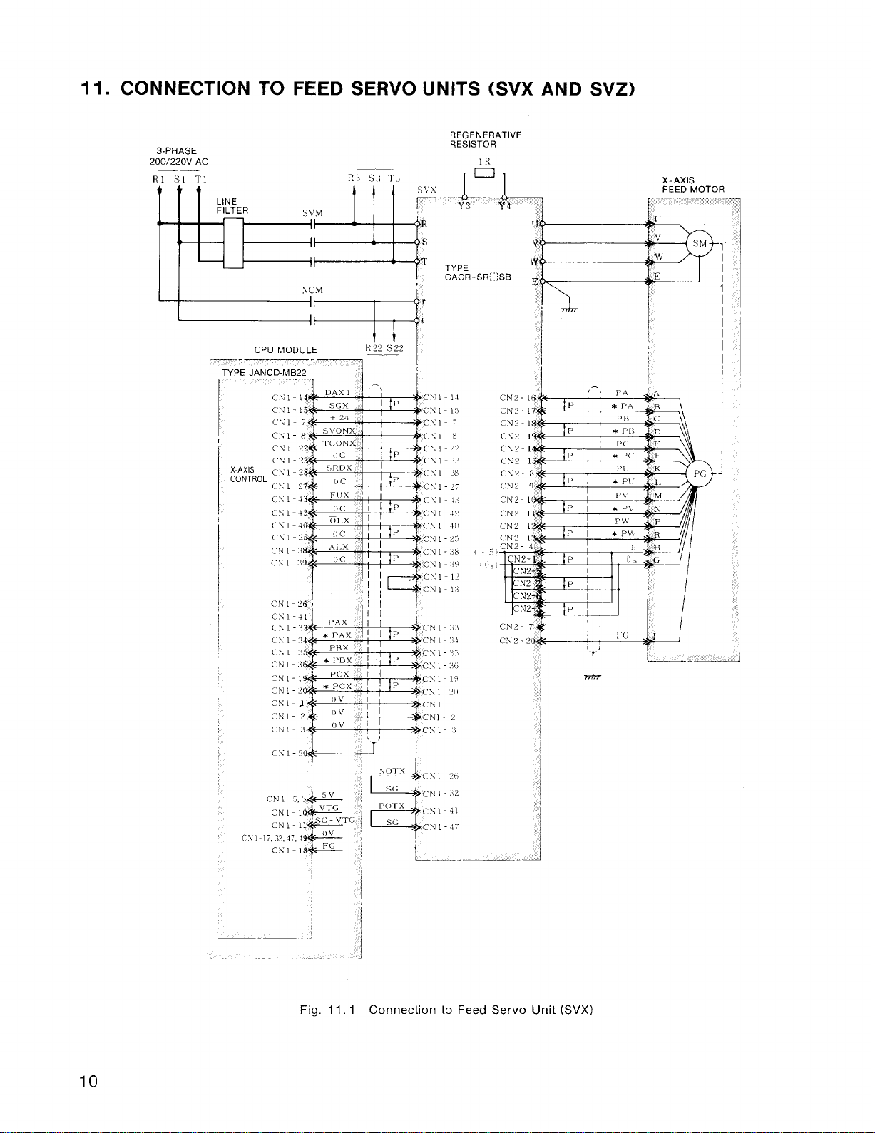
11. CONNECTION TO FEED SERVO UNITS (SVX AND SVZ)
REGENERATIVE
3-PHASE
200/220V AC
R1 S1
T1
R:3 S:3 T:]
RESISTOR
..A
Y3
Y4
TYPE
SC.M
c\ l-x
(’N 1-22
CN 1-.38
cY1-:i9
(.N 1- ?tj ,
CS 1-41
CS I-.33
CS I-3*
c\ 1-.15
II
I
TYPE JANCD-M B22
r
X-AXIS
I
CACR-SR{”;SB
r
‘~’(;:;cN2-
\
CN2-1,
CN2-)
CN2-I
CS2-1
CX2-1
CN2-1
CX2- [
~~z. ,
Chlz-1
CN2-1
CN2-1
CN2-1
CN2- 4
.
CN2
CN2
CN2
CN2
“E
CN2- 7
C12-2(
10
CN1-2
CK 1-2
CN 1-:+
CY1
.—
Fig. 11.1 Connection to Feed Servo Unit (SVX)
Page 17
REGENERATIVE
~D RESISTOR
. ..
3-PHASE
200/220V AC
R ‘+
s .1
‘r .3
13’
,-!
!IP
1P
B
,1P
II
II
Ii
1!
~
1’
1’
i)
@
J,
~.a
R
:s
T
l.,
cN 1-11
-s1-1.7
CN I-7
CNI-8
CN 1-22
‘CN1 -2”;
,CN 1-28
P
‘:CN 1-27
;CN1-t.+
‘CN1- $2
,Csl-io
P
CN1-?5
‘C N1- +8
P
:CNi-:\9
“CN1-12
‘C N1 -1{
k;N 1- .1.)
P
CN1-’3t
CNI-.I5
P
“CN 1-:<b
,’cN1-IY
P
c~l.z(,
CN 1-1
CN1- 2
‘CN1-.i
TYPE
CACR-SR; “SB
Y4
I
1
I
I
—.-
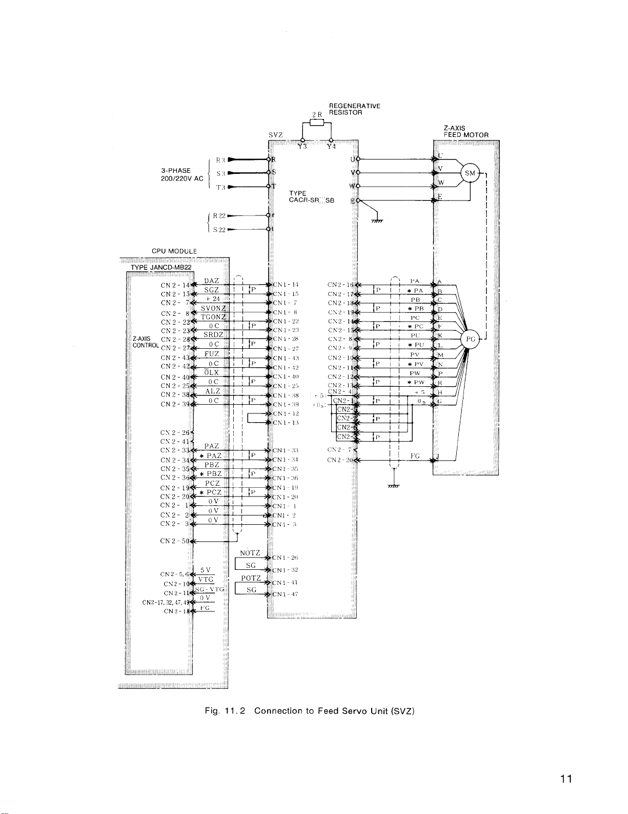
Fig. 11,2 Connection to Feed Servo Unit (SVZ)
11
Page 18
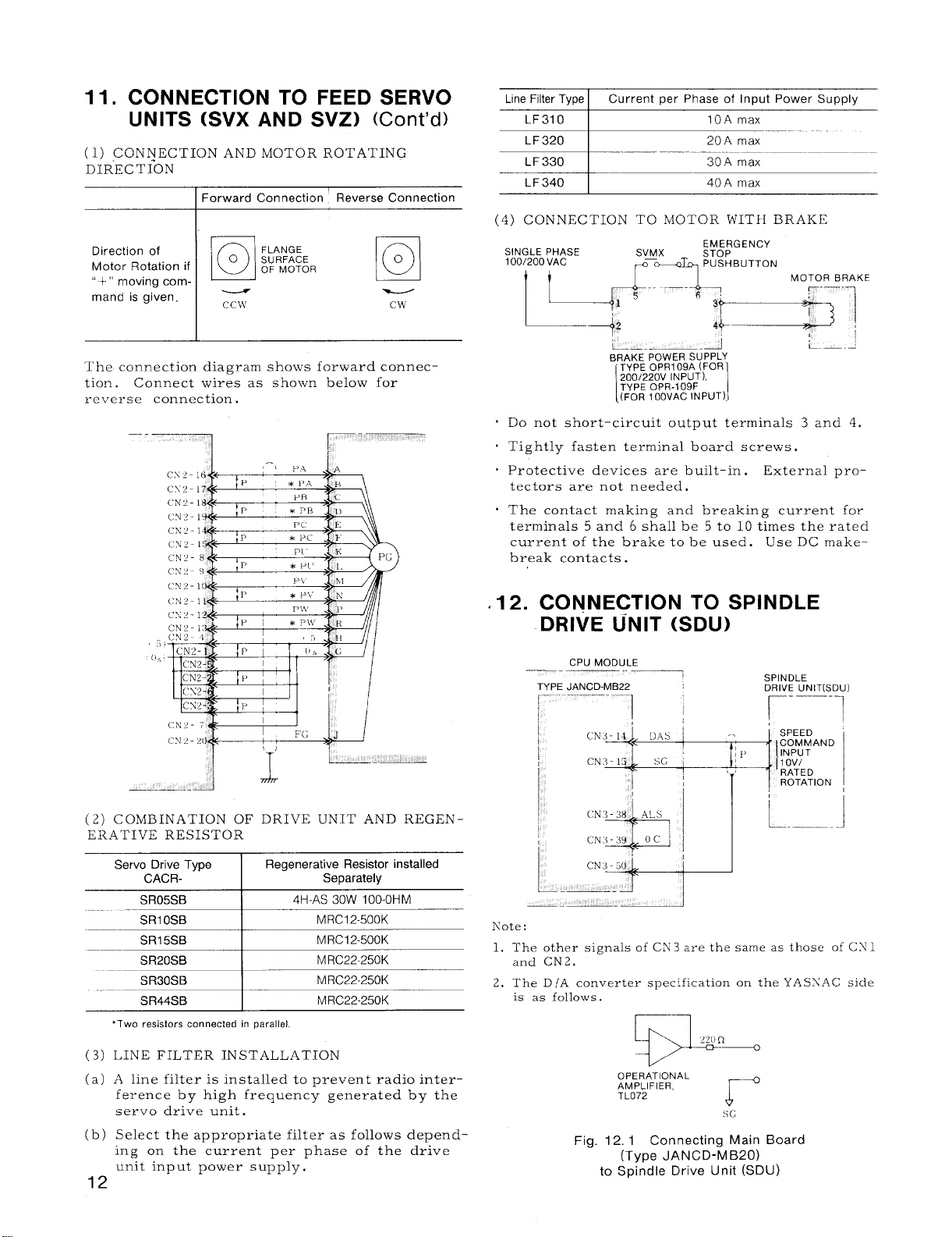
11. CONNECTION TO FEED SERVO
UNITS (SVX AND SVZ)
(1)
CONNECTION AND MOTOR ROTATING
DIR”ECTfON
Forward Connection Reverse Connection
Direction of
Motor Rotation if
“ +” moving com-
g
mancl is given.
The connection diagram shows forward connection. Connect wires as shown below for
reverse connection .
o
cc ‘vi’
FLANGE
SURFACE
OF MOTOR
(Cent’d)
o
g
Cw
Line Filter Type Current per Phase of Input Power Supply
o IOA max
LF31
LF 320
LF330
LF 340
I
I
max
20A
30A max
max
40A
(4) CONNECTION TO MOTOR WITH BRAKE
SINGLE PHASE
100/200 VAC
SVMX
@ ~ PUSHBUTTON
EMERGENCY
STOP
MOTOR BRAKE
u--” “---+-1
+2 :~-’]
L. —. —._
BRAKE POWER SUPPLY
TYPE OPR1 09A (FOR
200/220V INPUT),
TYPE OPR-109F
(FOR 100VAC INPUT)
[
.d
I
Do not short-circuit output terminals 3 and 4.
Tightly fasten terminal board screws ,
Protective devices are built-in .
tectors are not needed,
The contact making and breaking current for
terminals 5 and 6 shall be 5 to 10 times the rated
current of the brake to be used. Use DC make–
break contacts .
i-—. —
External pro-
(2) COMBINATION OF DRIVE UNIT AND REGEN-
ERATIVE RESISTOR
Servo Drive Type
CACR-
SR05SB
SR30SB
SR44SB
*Two resistors connected in parallel
LINE FILTER INSTALLATION
(3)
A line filter is installed to prevent radio inter-
(a)
ference by high frequency generated by the
servo drive unit.
Select the appropriate filter as follows depend-
(b)
ing on the current per phase of the drive
unit input power supply,
Regenerative Resistor installed
Separately
4H-AS 30W 10O-OHM
—
MRC22-250K
MRC22-250K
12
.12. CONNECTION TO SPINDLE
DRIVE UNIT (SDU)
CPU MODULE
TYPE JANCD-MB22
~_..-——.
1
Kote:
The other signals of CN3 are the same as those of CS 1
1.
and CN2.
2. The D 1A converter specification on the YASXAC side
is as follows.
*
OPERATIONAL
AMPLIFIER,
TL072
Fig. 12.1 Connecting Main Board
(Type JANCD-MB20)
to Spindle Drive Unit (SDU)
r
SPINDLE
DRIVE UN IT(SDU)
r-—-l
Page 19
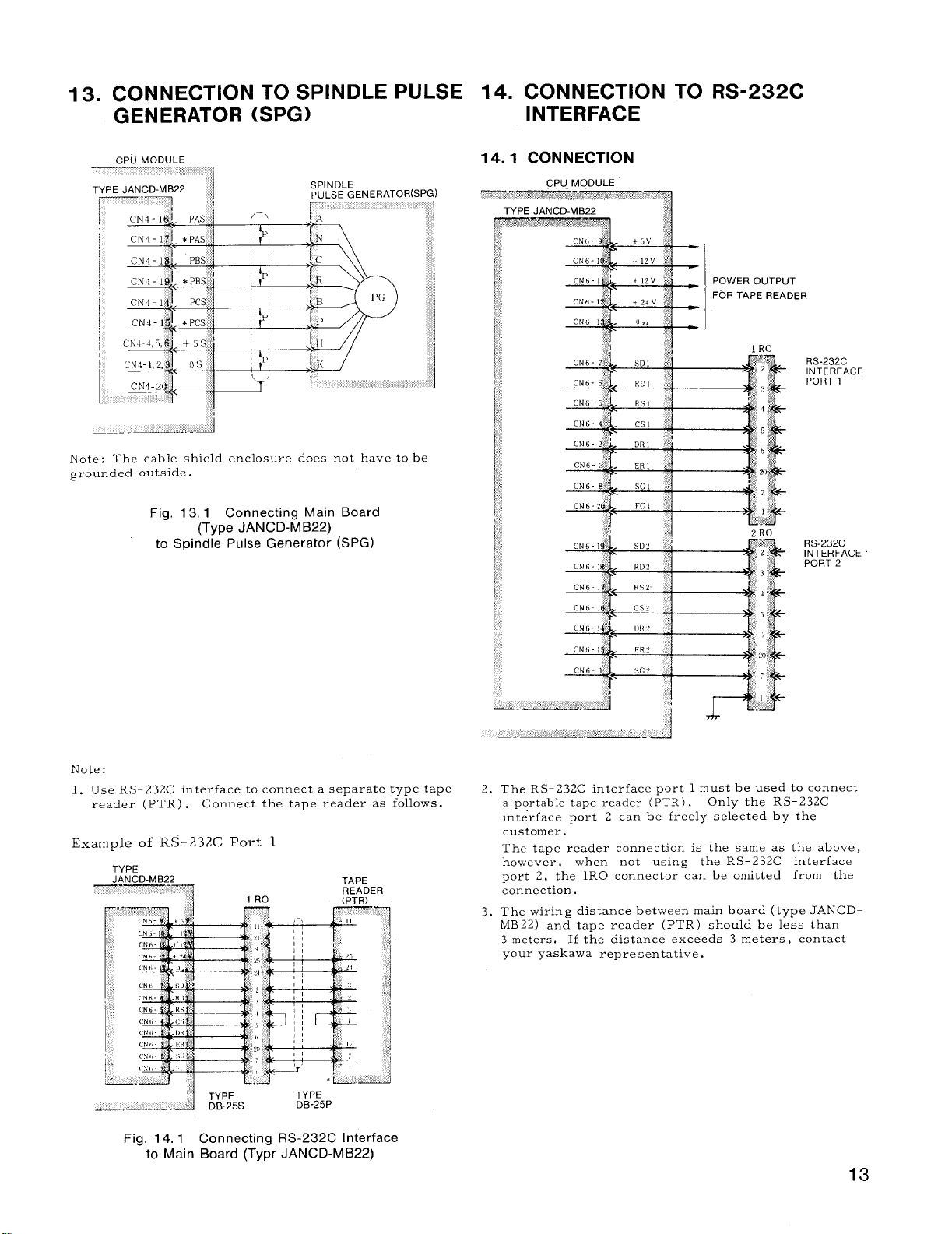
13. CONNECTION TO SPINDLE PULSE
GENERATOR (SPG)
Note: The cable shield enclosure does not have to be
grounded outside.
14. CONNECTION TO RS-232C
INTERFACE
POWER OUTPUT
FOR TAPE READER
Fig. 13, 1 Connecting Main Board
Note:
1. Use RS- 232C interface to connect a separate type tape
reader (PTR) .
Example of RS-232C Port 1
TYPE
(Type JANCD-MB22)
to Spindle Pulse Generator (SPG)
Connect the tape reader as follows.
2. The RS-232C interface port 1 must be used to connect
a portable tape reader (PTR) .
interface port 2 can be freely selected by the
customer.
The tape reader connection is the same as the above,
however, when not using the RS-23ZC interface
port 2, the lRO connector can be omitted from the
connection.
3. The wiring distance between main board (type JANCD-
MB22) and tape reader (PTR) should be less than
3 meters. If the distance exceeds 3 meters, contact
your yaskawa representative.
Only the RS-232C
Fig. 14.1 Connecting RS-232C Interface
to Main Board (Typr JANCD-M B22)
13
Page 20
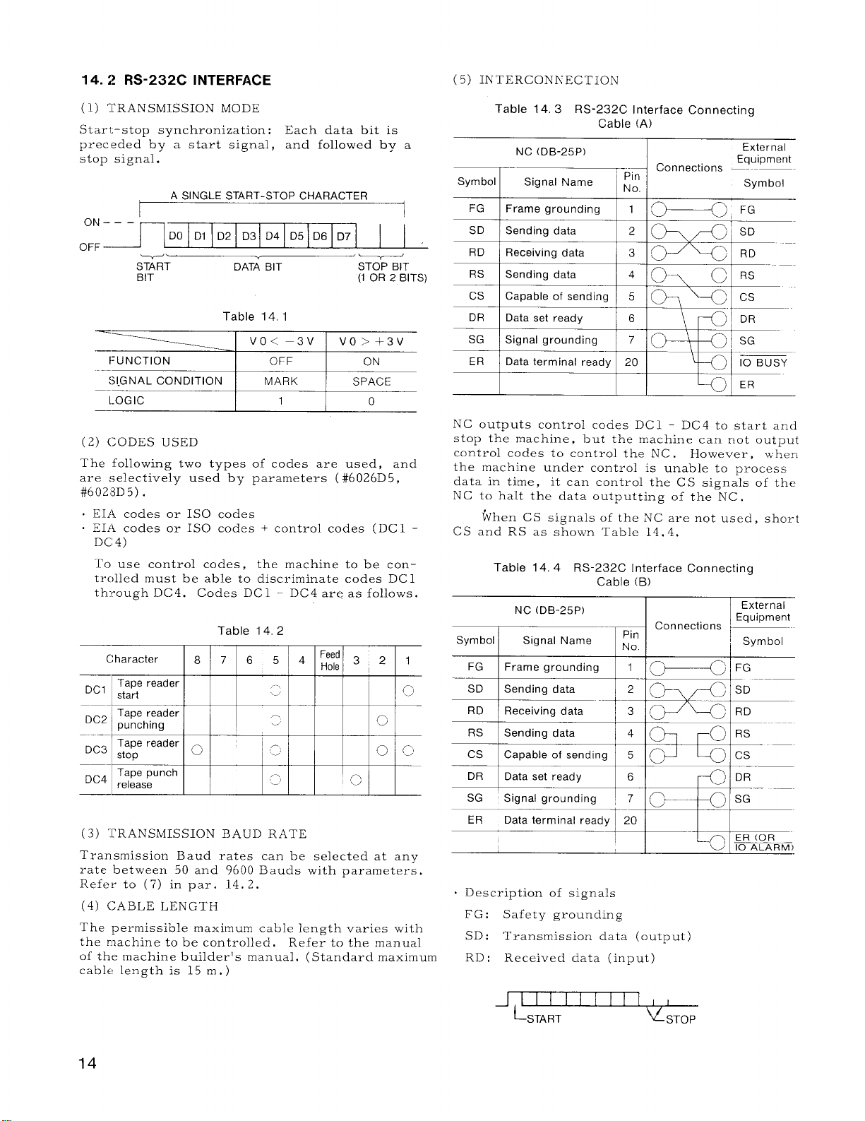
14. :? RS-232C INTERFACE
(5) INTERCONNECTION
TRANSMISSION MODE
(1)
Starl;-stop synchronization :
preceded by a start signal,
stop signal.
A SINGLE START-STOP CHARACTER
I
ON–––’
OFF –
(2) (;ODES USED
The following two types of codes are used, and
are :selectively used by parameters (#6026D5,
#6028D5) .
0 EIA codes or 1S0 codes
EIA codes or 1S0 codes + control codes (DC 1 -
.
DC4)
To use control codes , the machine to be controlled must be able to discriminate codes DC1
th-t-ough DC4. Codes DC 1 - DC4 are as follows.
DC, Tape reader .-
5 Y
START DATA BIT
BIT
Character
start
DI D2 D3 D4 D5 D6 D7
DO
Table 14, 1
Table 14.2
8 7 65 4 ::; 32
Each data bit is
and followed by
...
.
STOP BIT
(1 OR 2 BITS)
~
{..’
Table 14.3 RS-232C Interface Connecting
Cable (A)
a
-FG I Frame grounding
SD Sending data
RD Receiving data
RS
NC outputs control codes DC1 - DC4 to start and
stop the machine, but the machine can not output
control codes to control the NC .
the machine under control is unable to process
data in time, it can control the CS signals of the
NC to halt the data outputting of the NC.
CS and RS as shown Table 14.4,
Symbol
1
/.
FG I Frame grounding
SD
RD
+
NC (DB-25P)
Connections —---—-
Signal Name
Sending data 4
fihen CS signals of the NC are not used, short
Table 14.4 RS-232C Interface Connecting
NC (DB-25P)
Signal Name
Sending data
Receiving data
~ Pin
No.
1
I 1 I ~~) FG
2
~+ ‘-
3
—
1 !
However, when
Cable (B)
Connections \
Pin
No.
I
T
I ‘ 10
--{’ME
External
Equipment
Symbol
Cl RS
I
ER
External
Equipment
~ Symbol
~, ~FG
(3) TRANSMISSION BAUD RATE
Transmission Baud rates can be selected at any
rate between 50 and 9600 Bauds with parameters.
Refer to (7) in par. 14.2.
(4) (;ABLE LENGTH
The permissible maximum cable length varies with
the machine to be controlled, Refer to the manual
of the machine builder’s manual. (Standard maximum
cable
length is 15 m, )
14
DR
Data set ready
SG
Signal grounding
ER
Data terminal ready 20
, Description of signals
FG: Safety grounding
SD: Transmission data (output)
RD :
Received data (input)
-fIl I I
I 61
+’*-P
1,, ,,
L-START
fl~DR
~sTop
Page 21
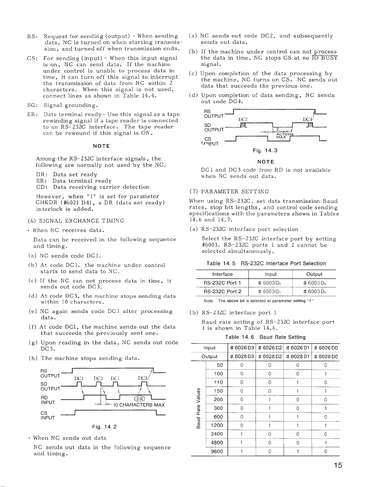
RS:
Request for sending (output) - When sending
data, NC is turned on when starting transmis-
sion, and turned off when transmission ends.
Cs:
For sending (input) - When this input signal
is on, NC can send data. If the machine
under control is unable to process data in
time, it can turn off this signal to interrupt
the transmission of data from NC within 2
characters, When this signal is not used,
connect lines as shown in Table 14.4.
SG :
Signal grounding.
Data terminal read~ - Use this signal as a tape
ER :
rewinding signal if-a tape reader–is connect;d
to an RS-232C interface.
can be rewound if this signal is ON .
NOTE
Among the RS-232C interface signals, the
following are normally not used by the NC.
DR: Data set ready
ER : Data terminal ready
CD: Data receiving carrier detection
However, when
CHKDR (#6o2l D4), a DR (data set ready)
interlock is added.
(6) SIGNAL EXCHANGE TIMING
- When NC receives data.
Data can be received in the following sequence
and timing.
(a) NC sends code DC1,
(b) At code DC1, the machine under control
starts to send data to NC.
(c) If the NC can not process data in time, it
sends out code DC3,
(d) At code DC3, the machine stops sending data
within 10 characters.
(e) NC again sends code DC1 after processing
data.
(f) At code DC1, the machine sends out the data
that succeeds the previously sent one.
Upon reading in the data, NC sends out code
(g)
DC3.
(h)
The machine stops sending data.
~RTPUT
SD
OUTPUT
RD
INPUT
Cs
INPUT
When NC sends out data
NC sends out data in the following sequence
and timing .
~
Ill!) is set for parameter
\
DC3
1’/
L“
Fig. 14.2
DC1
The tape reader
DC3
Dc 1
10 CHARACTERS MAX
/-
/ \,
o~
NC sends out code DC 2, and subsequently
(a)
sends out data.
(b)
If the machine under control can not process
the data in time, NC stops CS at no IO BUSY
signal.
(c)
Upon completion of the data processing by
the machine, NC turns on CS. NC sends out
data that succeeds the previous one.
Upon completion of data sending, NC sends
(d)
out code DC4.
~RTpUTJ
SD
ouTpuT~
Cs
‘3Nl~UT
DC1 and DC3 code from RD is not available
when NC sends out data.
PARAMETER SETTING
(7)
When using RS-232C , set data transmission Baud
rates, stop bit lengths,
specifications with the parameters shown in Tables
14.6 and 14.7.
(a)—RS-232C interface port selection
Select the RS-232C interface port by setting
#6003. RS-232C ports 1 and 2 cannot be
selected simultaneously,
Table 14.5 RS-232C Interface Port Selection
Interface Input output
RS-232C Port 1
RS-232C Port 2
Note: The above bit is selected at parameter setting “1 “
(b) RS-232C interface port 1
Baud rate setting of RS-232C interface port
1 is shown in Table 14.6.
Table 14.6 Baud Rate Setting
Input
output
I
I
I
I
I
] # 6026D3 I # 6026D2 I # 6026D1 I R 6026D0
I * 6028D3 I # 6028D2 I # 6028D1 I $ 6028D0
501 0 I o
100 IOIO
1101010
150
200
3001011
24001110
~
D~~
+;g+~R~
MAX
Fig. 14.3
NOTE
and control code sending
$ 6003Do
@f3003D1 46003 D,
I
I
I
0 0 1 1
0
1
I
I
DC4 ~
I L-
# 6003 D,
o
10
o
I
1
I
0
o
11
o
I
1
o
0
o
15
Page 22
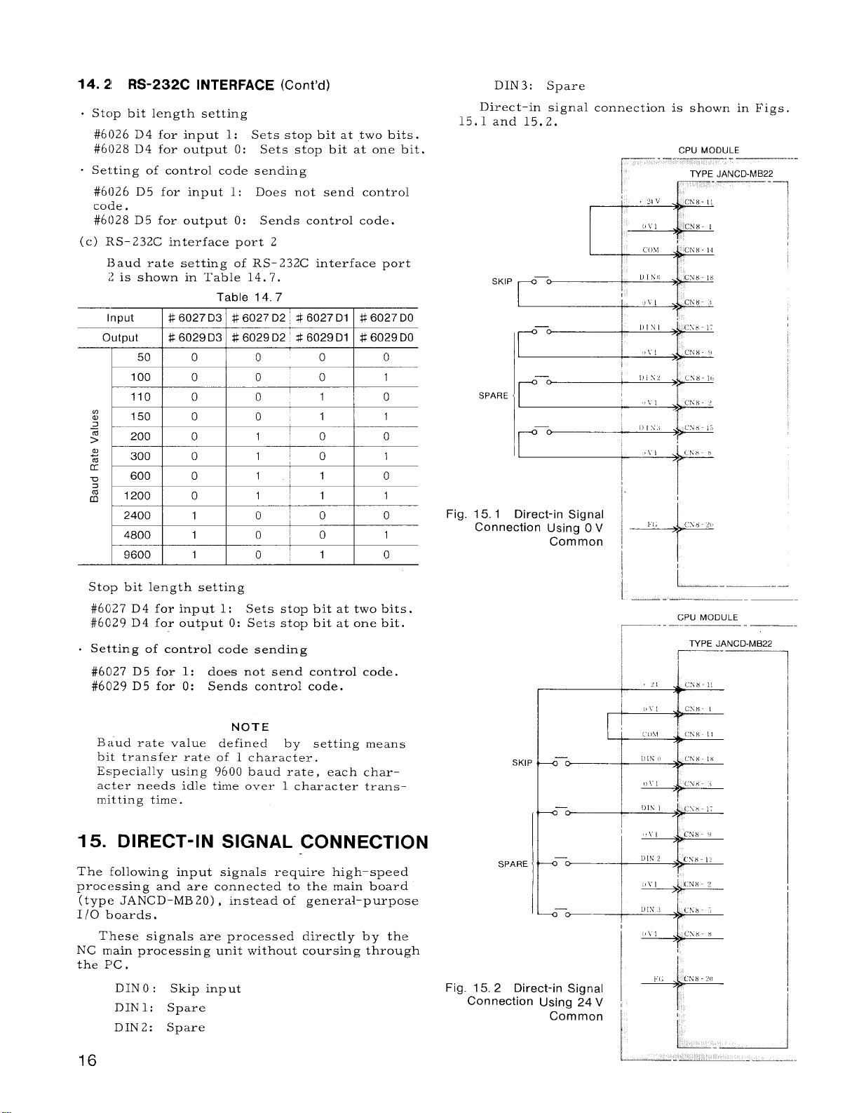
14. 2! RS-232C INTERFACE (Cent’d)
. Stc)p bit length setting
#6026 D4 for input 1:
#6028 D4 for output O:
. Setting of control code sending
#6026 D5 for input 1:
code .
#6028 D5 for output O: Sends control code.
(c) RS-232C interface port 2
13aud rate setting of RS-232C interface port
2 is shown in Table 14.7.
Input
output
# 6027 D3
# 6029 D3
50 0 0
100 0 0
110 0 0’1
m
a 150 0 0
3
z
200 0
>
m
%
K
u
:
m
300
600
1200 0
0 1’0
0
2400 1 0!0
4800
9600
1
1
Stop bit length setting
#6027 D4 for input 1:
#6C29 D4 for output O: Sets stop bit at one bit.
Setting of control code sending
#6C127D5 for 1:
#6029 D5 for O:
does not send control code.
Sends control code.
Sets stop bit at two bits.
Sets stop bit at one bit.
Does not send control
Table 14.7
# 6027 D2 $6027 D1
# 6029 D2 * 6029 D1
0
0
1 1
1’0
11
1
1
1 1
o~o
0’1
Sets stop bit at two bits.
# 6027 DO
# 6029 DO
D1N3: Spare
Direct-in signal connection is shown in Figs.
15,1 and 15.2.
SKIP
r’”
0
1
0
SPARE
0
1
0
o
1
0
Fig. 15.1 Direct-in Signal
Connection Using O V
Common
I
L.—--------
.—. ——
CPU MODULE
,
I
TYPE JANCD-MB22
~-
NOTE
Baud rate value defined by setting means
bit transfer rate of 1 character.
Especially using 9600 baud rate, each character needs idle time over 1 character trans–
m.itting time.
15. DIRECT-IN SIGNAL CONNECTION
The following input signals require high-speed
processing and are connected to the main board
(type JANCD-MB 20) , instead of general-purpose
1/0 boards.
These signals are processed directly by the
NC main processing unit without coursing through
the F’C ,
DINO:
Skip input
DIN1: Spare
DIN2: Spare
16
SKII
SPARE
Fig. 15.2 Direct-in Signal
Connection Using 24 V ,
Common I
CN8 -20
+
~ “ L-_A
Page 23
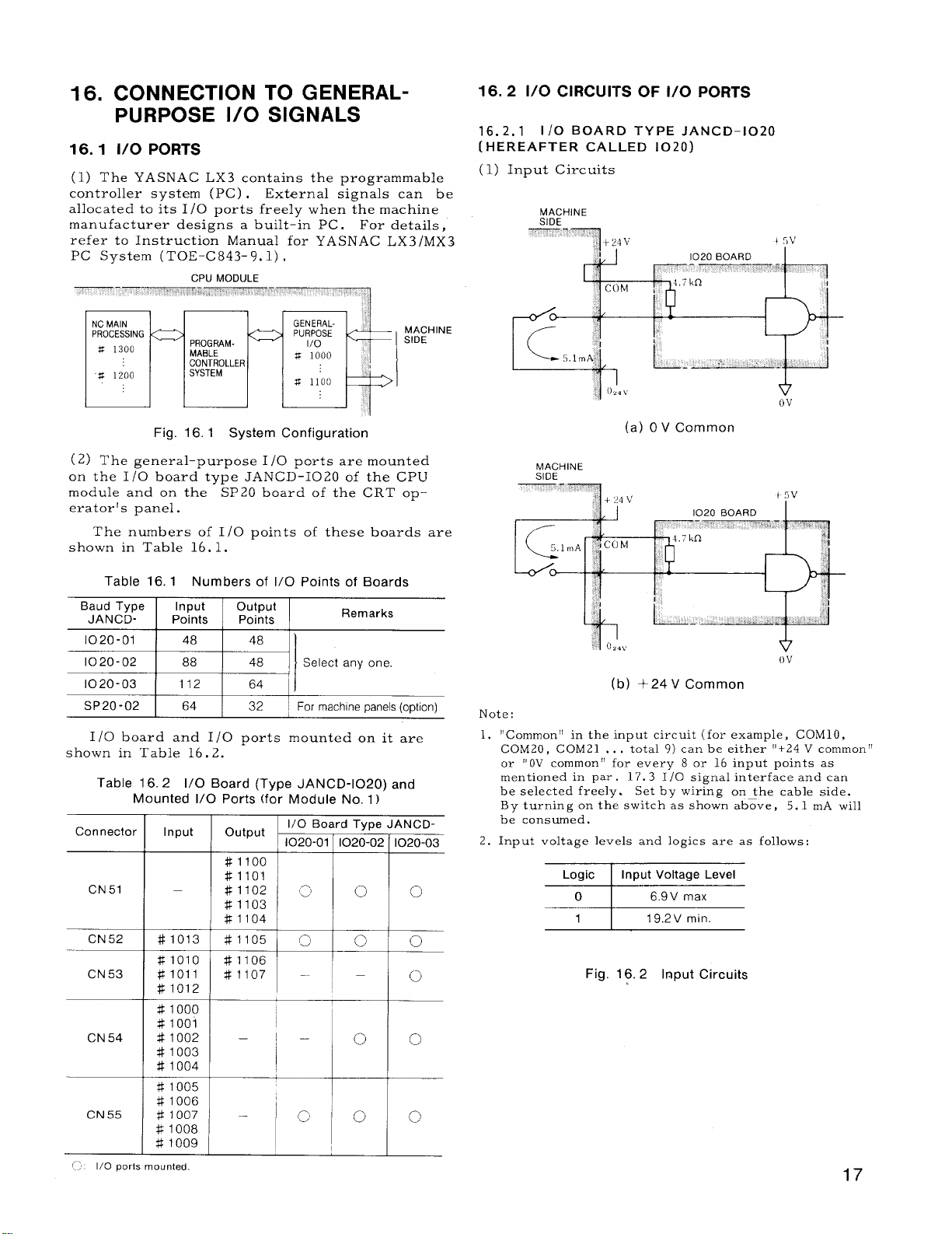
16. CONNECTION TO GENERALPURPOSE 1/0 SIGNALS
16.1 1/0 PORTS
The YASNAC LX3 contains the programmable
(1)
controller system (PC) . External signals can be
allocated to its 1/0 ports freely when the machine
manufacturer designs a built-in PC. For details,
refer to Instruction Manual for YASNAC LX3/MX3
PC System (TOE-C 843-9. 1) ,
—-
NC MAIN
PROCESSING
s 1300
CPU MODULE
,,$ ..~;,; <.> ,.,
‘““~
MACI
SIDE
m
“w 1200
I
I
16.2 1/0 CIRCUITS OF 1/0 PORTS
16. 2.1 1/0 BOARD TYPE JANCD-102O
(HEREAFTER cALLED 1020)
(1) Input Circuits
Fig. 16.1 System Configuration
(2) The general-purpose 1/0 ports are mounted
on the 1/0 board type JAN CD-1020 of the CPU
module and on the SP20 board of the CRT operator’s panel.
The numbers of 1/0 points of these boards are
shown in Table 16.1.
Table 16.1 Numbers of 1/0 Points of Boards
Baud Type
JANCD- Points
~
I /0 board and 1/0 ports mounted on it are
shown in Table 16.2.
Table 16.2 1/0 Board (Type JANCD-1020) and
Connectc
CN 51
CN52
CN53
Input output
Mounted 1/0 Ports (for Module No. 1)
Input output
—
#lo13
#lolo
#loll
#lo12
Points
~ For machine panels (option)
l/O Board Type JANCD-
1020-01
#lloo
#llol
#llo2
#llo3
#llo4
#llo5
#1106
#llo7
Remarks
I1020-02 1020-03
— —
# 1000
CN54
CN55
..
1/0 ports mounted
[,
# 1001
# 1002
# 1003
# 1004
# 1005
# 1006
# 1007
# 1008
# 1009
—
—
o
I
(a) OV Common
MACHINE
SIDE
ov
(b) +24V Common
Note:
1.
“Common “ in the input circuit (for example, COM1O,
COM20, COM21 . . .
or “ OV common” for every 8 or 16 input points as
mentioned in par . 17.3 1/0 signal interface and can
be selected freely.
By turning on the switch as shown above, 5.1 mA will
be consumed.
Input voltage levels and logics are as follows:
2.
0
~
1
total 9) can be either “+24 V common”
Set by wiring on the cable side.
19.2V min
I
0
0
Fig. 16.2 Input Circuits
0
c)
17
Page 24
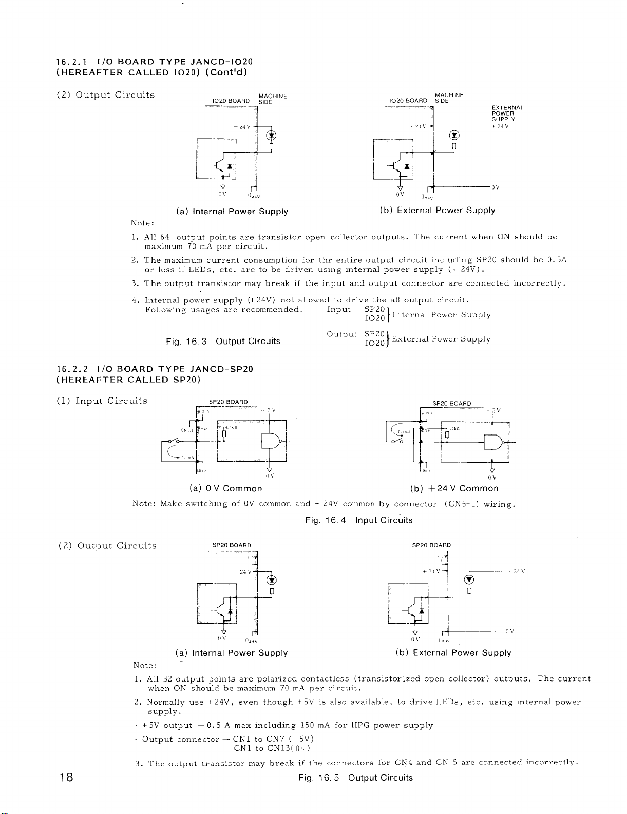
16. 2.1 1/0 BOARD TYPE JAN CD-1020
(HEREAFTER CALLED 1020)
(Cent’d)
(2) C)utput Circuits
(a) Internal Power Supply
Note:
1. All 64 output points are transistor open-collector outputs. The current when ON should be
maximum 70 mA per circuit.
2. The maximum current consumption for thr entire output circuit including SP20 should be O. 5A
or less if LEDs, etc. are to be driven using internal power supply (+ 24V) .
3. The output transistor may break if the input and output connector are connected incorrectly.
4. Internal power supply (+ 24V) not allowed to dri~,e the all output circuit.
Following usages are recommended.
Fig. 16.3 Output Circuits
16. 2.2 1/0 BOARD TYPE JAN CD-SP20
(HEREAFTER cALLEt3 sp20)
1020 BOARO slDE 1020 BOARD SIDE
$ fz:
Ov
O<..
MACHINE
Input
output SP20
SP20
~ozo Internal PO\\,er Supply
~020 External Po\\er Supply
MACHINE
02.,
(b) External Power Supply
)
)
(1) Input Circuits
Note: Make switching of OV common and + 24V common by connector (CN 5
(2) Output Circuits
18
BOARD
SP20
~,.
c,, , CO,, , ‘--”
Ego
*,, .
(a) OV Common
BOARD
SP20
—-— .
~d ~~:
ov
(a) Internal Power Supply
Note:
1. All 32 output points are polarized con tactless (transistorized open collector) outputs. The current
when Oh? should be maximum 70 m.A per circuit.
2. Normally use + 24V,
supply.
. + 5V output — O. 5 A max including 150 mA for HPG power supply
. Output connector – CN1 to CN7 (+5V)
3. The output transistor may break if the connectors for CN4 and
t 5\J
.— -
(1\;
Fig. 16.4 Input Circuits
,5
1
0,.,>
(b) External Power Supply
even though + 5V is also available, to drive
CN1 to CN13(Os)
Fig, 16.5 Output Circuits
(i v
(b) +24V Common
1) wiring.
SP20 BOARD
“1
‘c
UY
LEDs, etc. using internal power
Ch’ 5 are connected incorrectly.
Page 25

16.3 1/0 SIGNAL INTERFACE
16.3.1 1/0 20 BOARDS
------ .
.i
/
1
ADDRESS BIT
No. No
#looo. o
#looo 1
2
<,
:{ 20 )
I
%
/:( 35)
‘p
z( 36)
~
‘(6)
>,
;
1;’(22) —
t,.
,,
k
#looo.
#looo 3
b
#looo 4
#looo. 5
#1000. 6
#looo. 7
#lool o
#lool. 1
#lool 2
*1 OO1. 3
#lool. 4
#lool. 5
,-,
T 1
1
I }
+, ... c
*.
f,., ~ -
L
COM 30
:<,,,:,;::<, ;i..,,; ,;,. ,,; ...,,:,.“~,,,.,,.,,.,,,,, l,, ,. .,, *$*
—
Note:
1. This connection example shows +24 V common.
O V common is also available.
Refer to par. 16.2.1,
I/0 Board Type JANCD–1020 for connection details ,
2. The addresses are those for module No. 1. The address
layouts for modules Nos.
above starting with newer addresses.
B (3) , Address Classification for details.
2 to 4 are the same as shown
Refer to Appendix
Fig. 16.6 Connection to Address and Bit Nos.
#1000,0 to #1001.7 on 1020 Board
I
—
””,. “
. . . .
19
Page 26
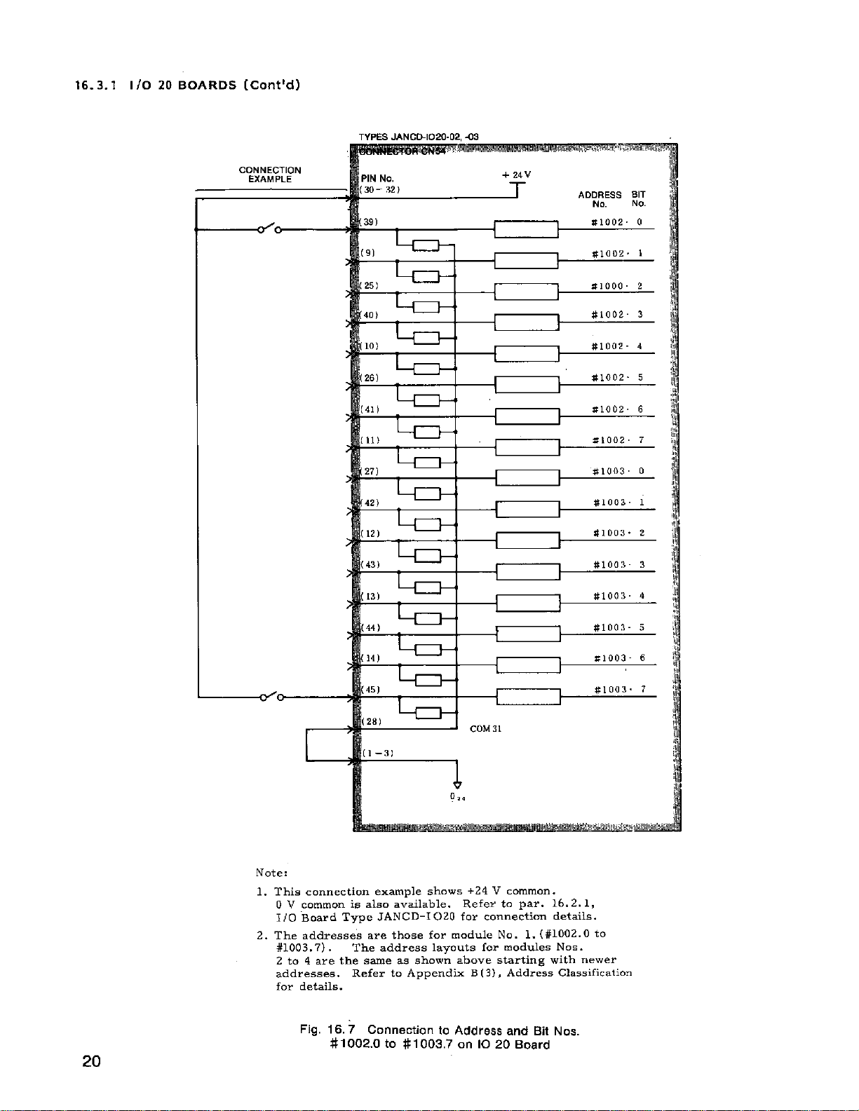
16.3.1 1/0 20 BOARDS (Cent’d)
TYPES JANCW1020 .02, -09
1-
,.,
<3!
K31
441
141
“.) —
—
[
I
I
Note:
1. This connection example shows +24 V common.
0 V common is also available. Refer to par. 16.2.1,
1/0 Board Type JANCD-I 020 for connection details.
2. The addresses are those for’ module No. 1. (#1002. O to
#loo3.7).
2 to 4 are the same as shown above starting with newer
addresses. Refer to Appendix B (3) , Address Classification
for details.
The address layouts for modules No,
$1003. 2
#l Oa:{ 3
*1 OO:3. d
U1OO3- 5
s1OO3. 6
20
Fig. 16.7 Connection to Address and Bit Nos.
#1002.O to #1 003.7 on 1020 Board
Page 27
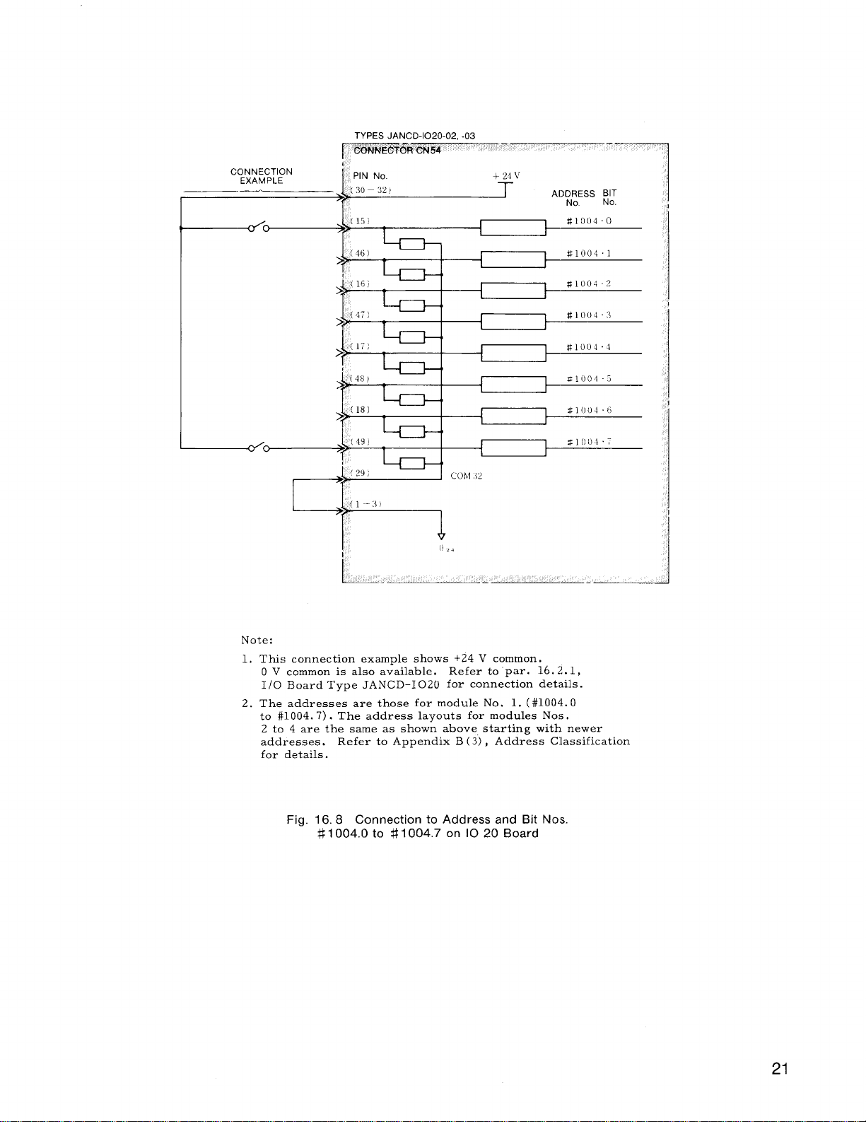
CONNECTION
EXAMPLE
> p
5 %
> w
$
<30–321
(
( 17 )
(48)
(~L);
PIN No.
[16)
,
Cohl.12
+
+ ~ii,
ADDRESS ~[
No
#loo40
#loo41
#loo4. ?
1
M1O(I4:I
#loo4.4
1
S1OOI5
$1004{5
1
31(1017
1
E :
Note:
1, This connection example shows +24 V common.
0 V common is also available. Refer to par. 16.2.1,
I/0 Board Type JANCD-1020 for connection details.
2. The addresses are those for module No. 1. ( #1004. O
to #1004. 7) . The address layouts for modules Nos.
2 to 4 are the same as shown above starting with newer
addresses.
for details.
Fig. 16.8 Connection to Address and Bit Nos
{1--?)
Refer to Appendix B (3) , Address Classification
#1 004.0 to #1004.7 on 1020 Board
21
Page 28

16. 3.1 1/0 20 BOARDS (Cent’d)
[1’>. ...
\a” —aL)
r
f
1
I
ADDRESS BIT
No
No
22
Note:
1. This connection example shows +24 V common.
O V common is also available,
I/0 Board Type JAN CD-1020 for connection details,
Refer to par. 16.2.1,
2, The addresses are those for module No. 1. (#1005. O
to #1006. 7) . The address layouts for modules Nos.
2 to 4 are the same as shown above starting with newer
addresses. Refer to Appendix B (3) , Address Classification
for details.
Fig. 16, 9 Connection to Address and Bit Nos.
#1 005.0 to #1 006.7 on 1020 Board
Page 29

CONNECTION
EXAMPLE
d
,,.
<A
1
~?{16)
~~
(15)
>%
1
,,:
t’{14)
>2
r:
+24V
ADDRESS BIT
No. No.
#loo7. o
#loo7. 1
#loo7 2
1
#loo7 3
)
1
#looi’. 4
S1OO7 5
$1 OO7. 6
#loo7. 7
#1008 O
#1008 1
#1008 2
#1008. 3
~~:f41)
>?
,,’
I
,.,
...
I
~
Note:
1. This connection example shows +24 V common.
O V common is also available.
1/0 Board Type JAN CD–1020 for connection details.
2, The addresses are those for module No. 1. (#10Ct7. O
to #1008. 7) . The address layouts for modules Nos.
2 to 4 are the same as shown above starting with newer
addresses. Refer to Appendix B(3) , Address Classification
for details,
+1
o
,.
Refer topar.16. 2.1,
#1008 4
#1008 5
#1008 6
#1008. 7
Fig. 16.10 Connection to Address and Bit Nos.
#1007.O to #1008.7 on 1020 Board
Page 30

16. 3.1 1/0 20 BOARDS (Cent’d)
CONNECTION
-~ ‘0 ‘0
TYPES JAN CD-1020 -01 -02, -03
por4MEcFm CNW -
ADDRESS BIT
I
J
COLI!2
Note:
1. This connection example shows +24 V common.
O V common is also available,
1/0 Board Type JANCD-1020 for connection details.
2. The addresses are those for module No. 1. (#1009. O
to #1009. 7) . The address layouts for modules Nos.
2 to 4 are the same as shown above starting with newer
addresses.
Refer to Appendix B (3) , Address Classification
for details.
Fig. 16.11 Connection to Address and Bit Nos.
#1 009.0 to #1 009.7 on 1020 Board
Refer to par, 16.2.1,
Page 31
<0
..
r
I [39)
F
i
(9)
>%
1
(25)
i
(40)
>2
I
[41)
>>
I
(111
1,’(27)
‘1
I ADDRESS BIT
-t I
1
}
t
No.
#lolo o
#lolo. 1
#lolo 2
#lolo 3
#lolo 4
Zlolo 5
#lolo 6
#lolo 7
#loll o
#loll 1
#loll. 2
No.
~~>
E [43)
>>
!13)
>2
(44)
1
(14;,
[45)
I
!
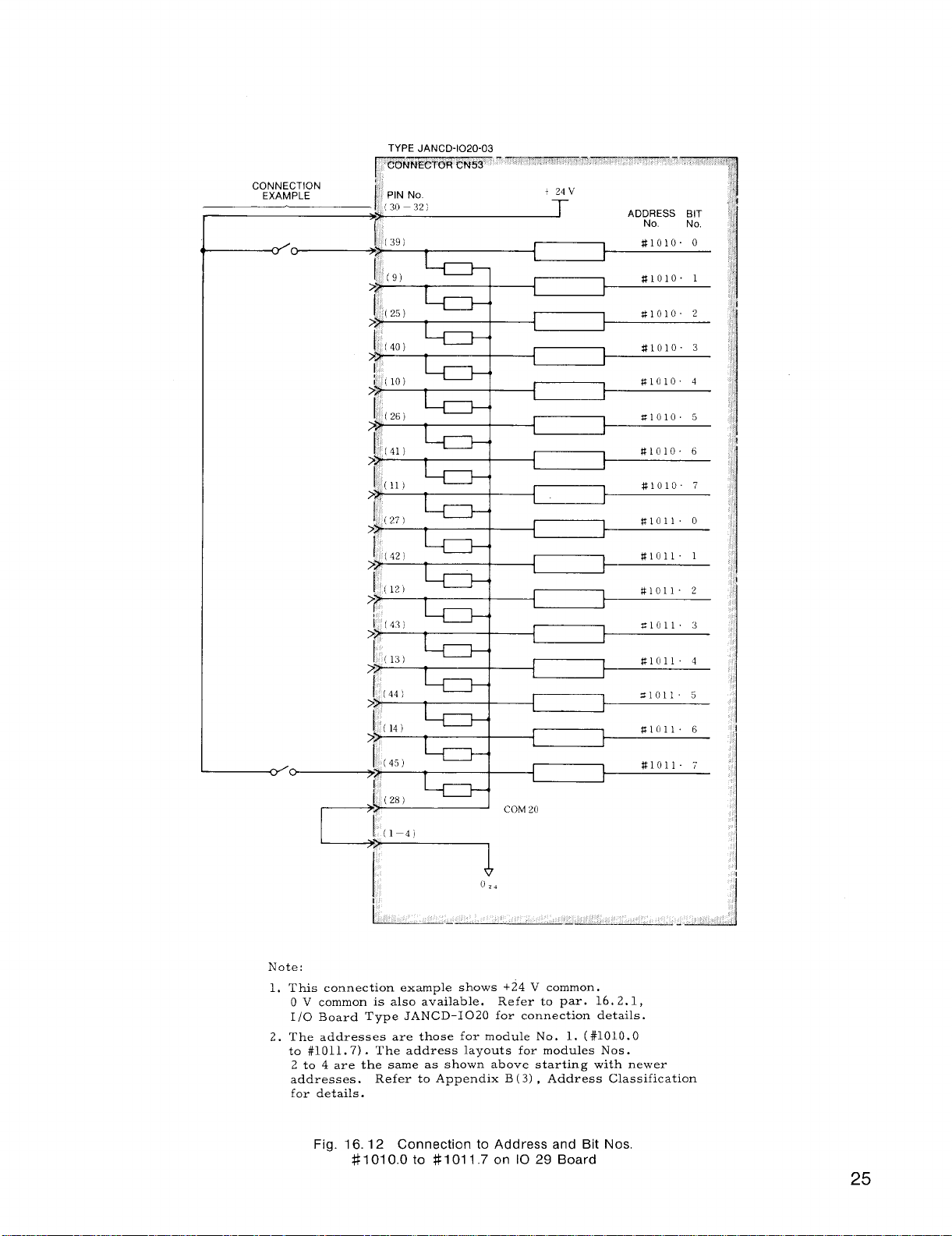
Note:
1, This
2. The addresses are those for module No. 1. (#1010. O
connection example shows +24 V common.
0 V common is also available. Refer to par. 16.2.1,
Board Type JANCD-1020 for connection details.
1/0
to #1011. 7) . The address layouts for modules Nos.
2 to 4 are the same as shown above starting with newer
addresses.
for details.
Refer to Appendix B (3) , Address Classification
-11
I
Xloll 3
flloll 4
Sloll, 5
S1OI1 6
#loll. 7
Fig. 16.12 Connection to Address and Bit Nos.
#1010.O to #101 1.7 on 1029 Board
25
Page 32

16. 3.1 1/0 20 BOARDS (Contld]
i
L_
Note :
1. This coczection exampl. she%-s -24 V cor,mon.
0 1, common is also zrvailzblc.
1/0 EwaYd T>rpc JANCI)102O for connection details.
2, The addresses are those [or
to #l 012. 7) . The address la>-outs for module, .Nos
2 to 4 are the sam,. ;is showri zbove sttirting with ne%ver
address... Refer to Appe,,clix B (3) , Addre8s Classification
for details,
Fig. 16.13 Connection to Address and Bit NOS
E1012.O to $1012.7 on 10 20 Board
Refer to.par. 16.2.1,
~,”d”l~ No. 1. (#1012. O
Page 33

~L[ 13, ~o)
f“
I ADDRESS BIT
No.
No
Note:
1.
This connection example shows +24 V common.
O V common is also available.
I/0 Board Type JANCD-1020 for connection details.
2.
The addresses are those for module No. 1. (#1013. O
to #1013. 7) . The address layouts for modules Nos.
2 to 4 are the same as shown above starting with newer
addresses. Refer to Appendix B(3) , Address Classification
for details.
3.
Connector CN52 can be used conveniently for interface with
the spindle drive unit,
Refer to par. 16.2.1,
Fig. 16.14
27
Page 34

16. 3.1 1/0 20 BOARDS (Cent’d)
TYPES JANCD-1020-01, -02, -03
ADDRESS BIT
No No
r“
+ 24 ~’
C%MN~cTOR GM31
PIN No
7
:ill :12 )
CONNECTION
EXAMPLE
1~
=11 [)().1
$11 [,1 11
=11111.1
#lllJl 1
X11(11. 5
(Zfj)I
t
I
4<
1
2’)<~
I
2:])
---i
4
I 4
’20)I
1
I
3
Note:
1. This connection example shows +24 V common.
O V common is also available.
I/0 Board Type JANCD-1020 for connection details.
2. The addresses are those for module No. 1. (#1100. O
to #1101. 7) . The address layouts for modules Nos.
2 to 4 are the same as shown above starting with newer
addresses.
for details.
Refer to Appendix B , Address Classification
Refer to par, 16.2,1,
Fig. 16.15 Connection to Address and Bit Nos
#1100.O to
#1101,7 on 1020 Board
Page 35

TYPES JANCD-1020-01 .-02. -03
#llo2. 5
#1102 6
#llo2. 7
$1103 0
#llo3. 2
*1103 5
#1103 6
#llo3 7
+1
(35}1
1~
(34)i~
I
1
(33) ~
1
’181,~
+
(16~~,
}
1’ --i
(131.’
,~
(12}~
1
]
(11)’,
}
I
m
Note:
1. This connection example shows +24 V common.
0 V common is also available. Refer to par. 16.2.1,
I/0 Board Type JANCD-1020 for connection details.
2. The addresses are those for module No. 1. (#1102. O
to #1103. 7) . The address layouts for modules Nos.
2 to 4 are the same as shown above starting with newer
addresses.
for details.
Refer to Appendix B (3) , Address Classification
Fig. 16.16 Connection to Address and Bit Nos.
#1 102.0 to #1 103.7 on 1020 Board
29
Page 36

16. 3.1 [/0 20 BOARDS (Cent’d)
Note:
1.2.This connection example shows +24 V common.
O V common is also available.
1/0 Board Type JAN CD-1020 for connection details,
The addresses are those for module No, 1. ( #1104. O
to #1104, 7) . The address layouts for modules Nos.
2 to 4 are the same as shown above starting with newer
addresses.
for details.
Refer to Appendix B (3) , Address Classification
Refer to par. 16.2.1,
Fig. 16.17 Connection to Address and Bit Nos.
#1 104.0 to #1104.7 on 1020 Board
30
Page 37

F1OO5. 2
#llo5 3
j,
[17)
I
}
‘5)2~
‘1
#llo5. 5
t
#1105 6
1
Note:
1. This connection example shows +24 V common.
O V common is also available.
1/0 Board Type JANCD-1020 for connection details.
2. The addresses are those for module No. 1. ( #1105, O
to #1105. 7) . The address layouts for modules Nos.
2 to 4 are the same as shown above starting witl~ newer
addresses.
for details.
Refer to Appendix B(3) , Address Classification
‘6;4+
j,
(12)
/
Refer to par. 16.2.1,
Fig. 16.18 Connection to Address and Bit Nos
#1 105.0 to #1 105,7 on 1020 Board
31
Page 38

16. 3.1 [/0 20 BOARDS (Cent’d)
TYPES JANCD-I020-03
32
Note:
1. This connection example shows +24 V common.
O V common is also available. Refer to par. 16.2.1,
I/0 Board Type JANCD-I 020 for connection details,
2. The addresses are those for module No.
to #1107. 7) . The address layouts for modules Nos.
2 to 4 are the same as shown above starting with newer
addresses, Refer to Appendix B (3) , Address Classification
for details.
1. (#1106. O
Fig. 16.19 Connection to Address and Bit Nos
#1106.O to #1 107.7 on 1020 Board
Page 39

16. 3.2 SP20 BOARDS
TYPE JANCD-SP20
C;;;;C;;N
‘IN No.
33)
2)
34) —
3)
19)
35)
4)
20)
36)
5:,
21)
+24V
ADDRESS BIT
No No
#looo. o
I I
1 J
I 1
L I
#looo. 1
#looo 2
#looo. 3
,
Wlooo 4
}
#looo. 5
t
#1000. 6
t
#looo. 7
—
I i
I
#lool o
J
*1 OO1. 1
I I
22)
38‘)
7)
I 1
1
J i
1
23) —
v
COLI30
Note:
1. This connectio~ example shows +24 V common.
0 V common is also available. Refer to par. 16.2.2,
I/0 Board Type JANCD-SP20 for connection details.
2. The addresses are those for module No. 1. (#1000. O
to #1001. 7) . The address layouts for modules Nos.
2 to 4 are the same as shown above starting with newer
addresses.
for details.
Refer to Appendix B (3) , Address Classification
1
1
1
#lool. 4
$1001 5
$1001 6
*1OO1. 7
Fig. 16.20 Connection of Address and Bit Nos
#1000.O to #1001.7 on SP 20 Board
Page 40

16. 3.2 SP20 BOARDS (Cent’d)
+24V
+24V
CONNECTION
EXAM PLE
11
do
o’~~
t
,<,
.,,
ADDRESS
1
I
!
1
No
#lo(12. o
#loo2 2
41002 3
$1002 4
S1OO2. 5
#loo2 6
Slooz. 7
#loo3 o
S1OO3 1
S1OO3. 2
#loo3 3
#loo3 4
#loo3 5
s1OO3, 6
#loo3 7
,’ PIN NO
/b+{
:,(39)
,.
(8) *1 OO2. 1
1(24) +
I
(40)
;?
,“
I
(411
1
j
(26)
1’
(421
COM 30
,
~
-1]
-i
+1
1
>>
[43)
>?
1>
(12)
>>
(28)
>?
i(44)
1
cOM 30
1
BIT
No.
Note:
1. This connection example shows +24 V common.
O V common is also available.
Refer to par. 16.2.2,
1/0 Board Type JANCD– SP20 for connection details.
2, The addresses are those for module No. 1. (#1002. O
to #1003. 7) . The address layouts for modules Nos.
2 to 4 are the same as shown above starting with newer
addresses.
Refer to Appendix B (3), Address Classification
for details.
Fig. 16.21 Connection of Address and Bit Nos.
002.0 to # 1003.7 on SP 20 Board
#1
Page 41

CONNECTION
EXAMPLE
I (13)
#
(29)
1
(45)
>>
I
(14)
>>
!
{30)
1
(46)
7
(15)
J (,,,
(47)
‘lb
(16)
I
(32)
>
i [4S)
>>
(17)
ADDRESS BIT
No.
No.
#loo4 o
#loo4 1
#loo4 2
1
}
t
1
1
~loo4 3
%1004. 4
#loo4 5
#loo4 6
SIO04 7
P1OO5. o
Z1OO5. 1
X1 OO5. 2
TIOO5. 3
#1005 4
-7
i
+
1
<49)
1
(18)
>>
~~> ( 50 )
Note:
1. This connection example shows +24 V common,
O V common is also available. Refer to
Board Type JANCD-SP20 for connection details,
1/0
2. The addresses are those for module No. 1. (#1004. O
to #1005. 7) . The address layouts for modules Nos.
2 to 4 are the same as shown above starting with newer
addresses. Refer to Appendix B (3) , Address Classification
for details.
Fig, 16.22 Connection of Address and Bit Nos.
k
1
#1004.O to #1 005.7 on SP 20 Board
#loo5 5
#1005 6
#1005. 7
par. 16.2.2,
Page 42

16. 3.2 SP20 BOARDS (Cent’d)
TYPE .JANCD-SP20
v
~~>
CONNECTION
EXAMPLE
PIN NO
I
I ,2,
(341
: (3,
1
[19!
>>
[
{ !35,
: (,,
121
?
!37)
>?
~ (6,
>>
(221
1381
1
COM 30
,
ADDRESS BIT
NO
#1006. O
t
#1006, 1
1
#loo6 2
1
#1006. 3
I
#1006. 4
$1006 5
I
s1OO6. 6
1
=1006. 7
$1007. 0
1
#loo7. 1
}
#loo7 2 ‘
$1007 3
#loo7. 4
1
W1OO7 5
I
No.
1,,
[23:1
~~y
Note:
1. This connection example shows +24 V common.
O V common is also available. Refer to par. 16.2.2,
1/0 Board Type JANCD-SP20 for connection details.
2. The addresses are those for module No. 1. (#1006. O
to #1007. 7) . The address layouts for modules Nos.
2 to 4 are the same as shown above starting with newer
addresses. Refer to Appendix B (3) , Address Classification
for details.
Fig. 16, 23 Connection of Address and Bit Nos.
#1006.O to #l 007.7 on SP 20 Board
I
02.
I
#1007. 6
#loo7. 7
Page 43

TYPE JANCD-SP20
ADDRESS BIT
No.
#l loo. o
~1 loo. 1
#l loo. 2
#l loo 3
#llo(o 4
#l loo 5
—
No.
+~4v
,, ,~fv, ;
~
.,.
,$,,$,<3?,
i5 J
i
ZONNEeTORcN5
7<:
.
4
:<*
~$
1
t
I
t
PIN No.
(33}
:39}
‘24)<~
:40)
125)
I
i
..
!
‘8)<+
I
‘g’<~
j,
CONNECTION
EXAM PLE
d
,
*11OO 6
#l loo 7
#llol o
#llol. 1
tilool 2
#llol 3
#llol 4
Sllol 5
#llol 6
#llol 7
l----
{
t
[ }—-----/
i 1
1
1
}
1
1
1
}
-d
I
‘41)<~
[10) ~
I
(26‘<~
‘42)<~
(11) ~
‘27}<:~
:43),
I
I12)
I
128)
1~
(44)
~~
+24V
,
4I
I
d
<
f
Note:
1. This connection example shows +24 V common.
0 V common is also available. Refer to
1/0 Board Type JANCD-SP20 for connection details,
2. The addresses are those for module No. 1. (#1100. O
to #1101, 7) . The address layouts for modules Nos,
2 to 4 are the same as shown above starting with newer
addresses. Refer to Appendix B (3), Address Classification
for details.
Fig. 16.24 Connection of Address and Bit Nos
#1100.O to #1101.7 on SP 20 Board
par. 16.2.2,
37
Page 44

SP20 BOARDS (Cent’d)
TYPE JANCD-SP20
ADDRESS BIT
No No
#llo2 1
#loo2 2
Z1102 4
S1103 1
#llo3. 2
Z1103. 3
+
PIN No :,
I
(30)I
1
{
1
1
I
1
!16]
1~
(32),.1
}
(48;’
I
<~
1
38
#1103. 3
I
N’ote:
1.2.This connection example shows +24 V common.
O V common is also available.
1/0 Board Type JANCD-SP20 for connection details.
The addresses are those for module No. 1. (#1102. O
to #1103. 7) . The address layouts for modules Nos.
2 to 4 are the same as shown above starting with newer
addresses.
for details.
Refer to Appendix B ( 3) , Address Classification
(49J
..
‘i
Refer to par. 16.2.2,
Fig. 16.25 Connection of Address and Bit Nos.
#1 102.0 to #1 103.7 on SP 20 Board
Page 45

17. CABLES
17.1 LIST OF CABLES
s
Connector Cable Type
The interface cables are furnished with or without
connectors. Those cables shown in Table 17.1
are available.
If the machine manufacturer is supplying the
cables,
prepare equivalent cables b;s~d on- the
cable specifications.
Table 17.1 List of Cables
Cable No.
Configuration
TYPES
MRP-50F01 ,
MR-50L
‘/()
)
TYPES
MR-50F01 ,
MR-50L
\
Remarks
● Servo drive unit
● Max cable length:
15m
Type KQVV-SB
. Spindle optical
encoder
s Max cable length:
15m
TypeKQVV-SB,DE8400093
0.2mmzX 10
ConnectorCN4:
TvDeMRP-20M01,MR-20LW
Dairs
● For input
sequence
Cable:
TypeKQVV,DE6428673
0,2mmzX20 cores
ConnectorCN6:
TypesMRP-20M01,MR20LW
RS-232C interface
1RO,2RO:
@
TypeDB-25S
Cable:
TypeKQVV,DE6428673
0.2mmzX20 cores
—
ConnectorCN8:
Not used
1/0
TypesMRP-20F01,MR-20LW
Cable:
TypeKQVV,DE6428673
02 mmzX20 cores
. Power supply for
CRT operator’s
TYPE
172026-1
TYPE
172026-1
panel
. Max cable length:
15m
@
TypeVCT, DE8402398
0.2mm2X 5 cores
@
—
ConnectorCN13:
Type172025-1
@
Cable:
TypeKQVV-SB,DE8402398
2mml X5 cores
*Connector and cable are separately provided
Not used
AC power supply
;able N
:able Type
CABLE-
AA [:: -1
*
*
CABLEJF[2-2
:ABLE-
Cc[:: -1
CABLECD II:-1
L
Connector Type
I
~
L
Cable Length L=5m
Cable Type
Configuration Remarks
● CRT operator’s
● Max cable length:
rypeKQVV-SB,DE8400093
).2mmzX10
pairs
1/0
;onnector C51, CN53,
;N54, CN55:
rypesMRP-50F01,
JR-50LW
;able:
rypeKQVV, DE8400095
).2mmzX 50 cores
;onnector:
“ypes MRP-20FOI, MR-20LW
;able:
‘ype KQVV, DE8408673
mmzX20 cores
).2
‘ypeMRP-20M01,M4
\MPLIFIERTERMINAL
‘ypeMR-20LW
rypeKQVV-SB,DE8400093
).2mmzX 10 Dairs
TYPES
M RP-20F01
M P-20L
(
/(
)
TYPES
MS31 086 20-29S
MS3057-1 2A\
TypeKQVV-SB, DE8400093
TYPES
MRP-20F01
(
MP-20L
/(
ul~~
)
TYPES
MS3108B 20-29S
MS3057-12A
TypeKQVV-SB,DE8400093
1/0
Manual
generator
Optical encoder
forward connecton
)
Optical encoder
reverse connection
)
panel signal
20 mm
pulse
39
Page 46
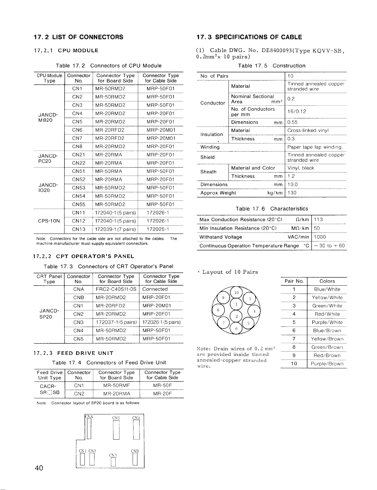
17.2 LIST OF CONNECTORS
‘ithstand-
17. 2.1 CPU MODULE
Table 17.2 Connectors of CPU Module
CPU tdodule
Type
JAN CDM B20
JAN CDPC20
JANCD-
1020
CPS-1 ON CN12 ‘ 172040-1 (5 pairs) I
Note Connectors for the cable side are not attached to the cables The
machine manufacturer must supply equivalent connectors.
17.2.2 CPT OPERATOR’S PANEL
T:~ble 17.3 Connectors of CRT Operator’s Panel
CRT Panel Connector ~ Connector Type
Type No. , for Board Side
JANCDSP20
17. 2.3 FEED DRIVE UNIT
Feed Drive Connector Connector TypeIConnector Type
Unit Type
CA(>R-
SR[:; SB
Note
Connector Connector Type
No. for Board Side for Cable Side
CN1 I MR-50RMD2 I MRP-50F01
CN2 I MR-50RMD2 I MRP-50F01
CN3 I MR-50RMD2 I MRP-50FOI
CN4 I MR-20RMD2 I MRP-20F01
CN5 I MR-20RMD2 I MRP-20F01
CN6 I MR-20RFD2 I MRP-20M01
CN7 MR-20RFD2 MRP-20M01
CN8 MR-20RMD2 MRP-20F01
CN21 MR-20RMA MRP-20FOI
CN22
‘CN51 MR-50RMA
CN52
CN53
CN54 ! MR-50RMD2
CN55 ~ MR-50RMD2
CN1l ~172040-1 (5 pairs) I 172026-1
CN13 ; 172039-1 (7 pairs) I
CNA I FRC2-C40S11-OS
CNB
CN1 MR-20RFD2
CN2
CN3
CN4
CN5
Table 17.4 Connectors of Feed Drive Unit
No. for Board Side
CN1
CN2 MR-20RMA
1
Connector layout of SP20 board is as follows:
MR-20RMA MRP-20F01
i MR-20RMA I MRP-20F01
i MR-50RMD2 I MRP-50F01
MR-20RMD2
MR-20RMD2 MRP-20F01
172037-1(5 pairs) 172026-1 (5 pairs)
MR-50RMD2
MR-50RMD2
MR-50RMF MR-50F
Connector Type
I
MRP-50F01
MRP-50F01
I
MRP-50F01
I
172026-1
172025-1
Connector Type
for Cable Side
Connected
MRP-20F01
MRP-20M01
MRP-50F01
MRP-50F01
for Cable Side
MR-20F
17.3 SPECIFICATIONS OF CABLE
Cable DWG. No. DE8400093(Type KQVV-SB,
(1)
0.2mm2x 10 pairs)
Table 17.5 Construction
No. of Pairs
I
I Material
Nominal Sectional
Conductorb:g
I Dimensions mm 0.55
Insulation
Winding
Shield
Sheath
Dimensions mm
Approx Weight
Max Conduction Resistance (20 “C)
Min Insulation Resistance (20°C)
Continuous Operation Temperature Range ‘C – 30 to + 60
o Layout of 10 Pairs
Note:
are provided inside tinned
annealed–copper stranded
wire.
W--K
Material and Color
k--”=
kg/km
Table 17.6 Characteristics
Drain wires of 0, 2 mmz
10
Tinned annealed copper
stranded wire
0.2
16/0.1 2
Cross-linked vinyl
03
—
Paper tape lap winding
Tinned annealed copper
stranded wire
Vinyl, black
1.2
100
130
Pair No. I
1
2 ] Yellow/White
3 I Green/White
7 Yellow/Brown
8 Green/Brown
Colors
I Blue/White
1
1
~e7Brown
40
Page 47

(2) Cable” DWG. No. DE 8400095 (Type KQVV-SB,
O. 2mm2x 50 cores)
Table 17.7 Construction
No. of Cable Cores
Material
Nominal Sectional
Conductor . Area
Insulation
Winding
Sheath
Finished Cable Diameter
Approx Weight
Max Conduction Resistance (20”C) O/km
Min Insulation Resistance (20”c)
Withstand Voltage
Continuous Operation Temperature Range ‘C
No. of Conductors
per mm
Dimensions mm 0.55
Material
Thickness mm 0.3
Material and Color. Soft vinyl, black
Thickness mmll.2
kg/cm
Table 17.8 Characteristics
50
Tinned annealed-copper
stranded wire
mm2 0’2
16/0.12
Cross-linked vinyl
I paper tape lap winding
mm Approx 13
230
Mfl. km
VAC/min
113
50
1000
–30to +60
Table 17.10 Characteristics
Max Conduction Resistance (20°C)
Min Insulation Resistance (20° C)
Withstand Voltage
Continuous Operation Temperature Range “C
. Details of Cable DWG.
No. DE 6428673
(4) Cable DWG. No. DE 8402398 (Type VCT,
2mm2x 5 cores)
Table 17.11 Construction
No. of Pairs
~:
Q/km ll13
MQ. km
VAC/min
15
1
Tinned annealed copperstranded wire
50
1000
–30to +60
. White
—
ConductorE:=
. Details
No. DE
(3) Cable DWG. No. DE6428673 (Type KQVV,
O. 2mm2x 20 cores)
No. of Cable Cores
Conductor Area
Insulation
Windinq
of Cable
8400095
Material
I
Nominal Sectional
E
No. of Conductors
per mm
Dimensions
Material
Thickness mm 0.3
k
DWG ,
Table 17.9 Construction
mm, 02
mm 16/0.12
mm 055
—
20
Tinned annealed-copper
stranded wire
I
L
Cross-linked vinyl
Paper tape lap winding
Stranding
Sheath
Dimensions mm
Max Conduction Resistance (20”C)
Min Insulation Resistance (20” C) MO. km
Withstand Voltage
o Details of Cable DWG, No, DE8402398
Material and Color
Thickness
I
~:
Vinyl, black
mm I Approx 1.9
13.0
Table 17.12 Characteristics
Q/km I 10.2
VAC/min
VINYL SHEATH
INCLUSION
50 or more
3000
Finished Cable Diameter
Approx Weight kg/km I 90
mm I 8.0
41
Page 48

18. STANDARD 1/0 SIGNALS
18.1 LIST OF NC STANDARD 1/0 SIGNALS
Input Signals
~–
#1300
#1301
#1302
$1303
21304
EDT ~
[
EDIT
MP 1
L
RAPID SPEED OVERRIDE
HZ
YA=G AXIS
~ lNH~ AFL : ABS ~ DRN I f3DT ~ DLK I MLK~~
INHIBIT
“EDIT
RETURN THREAD
TO
REFER-
ENCE
MEM
MEMORY
I ROV 2
—“
SELECT
M. S. T MANUAL DRY
LOCK ABS.
CUT UP
I ==~- I “s
MDI - TAPE —
HX
1.__:m7~”+x,
ERROR HIGH-SPEED SET UP
DETECT REWIND
ON
HANDLEI
STEP JOG
FV16 ;
L“Q 1 ‘=~~--1
FEEDRATE OVERRIDE/MANUAL JOG SPEED
MANUAL TRAVERSE AXIS
DIRECTION SELECT MULTIPLY SELECT
RUN DELETE LOCK LOCK BLOCK
BLOCK
POINT SET HOLD
RETURN
“DISPLAY
POSiTION
D2
D,
‘m
MANUAL
I yp’: M~l
MANUAL PG
MACHINE SINGLE
FEED
DO
MANUAL
RAPID
CYCLE
START
#1305
$1306
V1307
#1308
#1309
I ERR1
I
EXTERNAL ERROR
INPUT
SAGR
1
SPINDLE
SPEED
AGREEMENT
GRS
~.
DURING SPINDLE SGEAR
SHIFT
EOUT
NC
PROGRAM !:OGRAM !:OGRAM
PUNCH
OUT
BDT 9 I
ERR O I STLK ~
L~..—-
SPEED COMMAND COMMAND
CONSTANT “O
EVER
VERIFY INPUT
BDT 8
I I
lNTERLOCK
---x .1...::!. I “’” *-”
DEC==;R
REFERENCE POINT
GSC SSTP ~ SINV
EIN
BDT 7 BDT6 1
RWD
REWIND
s-
INVERT
DRSZ ‘ DRSX
DISPLAY RESET
OPTIONAL BLOCK DELETE
EOP I ERS ~ FIN
END OF EXTERNAL MST
PROGRAM RESET FIN READY
GR4 “~””’ GR3~ GR2 GR1
SPINDLE GEAR RANGE SELECT
BDT 5 BDT 4
OVERTRAVEL INPUT
1
I
MRD ~
MACHINE
—.-—-— —..----.
I “g
.-.. L-. .- 1
EXTC
TIME
CQUNT
BDT 3 BDT 2
I
42
Page 49

D,
#1310
#1311
WN 16
C—~=._ES..L.K 1 PRSTI ovc I
De
WN 8
EXTERNAL WORK NUMBER SEARCH
D5
WN 4
D4 D3 D2
WN 2 WN 1 SPC SPB SPA
SPINDLE OVERRIDE
CUTTING
INTERRUPT MODE
POINT
RETURN OFFSET
AUTO X AXIS PROGRAM OVERRIDE
HANDLE IMAGE
MIRROR RESTART CANCEL
DI Do
#1312
L~z:l
#13i3
L_:E.T--::-~ ““
#1314
#1315
#1316
71317
1–—J.— I
I
—i
SID8 ~ SID7 I SID6 ~ SID5 SID4 I SID3 I SID2
SPINDLE INDEX POSITION SET
TP8 ~ ‘P 2
i
COV16
MULTIPLE REPETITIVE CYCLES
TP 1 SID 12
COV8
COV4
—
—-r_—-.. ..
1 ‘--” ‘–slDll ~~s=
COV2 ~ Covl
1
I
I
SIDI
#1318
#1319
TOOL NO. SET FOR STORED
STROKE LIMIT
~ TLTM
TIMER
COUNT
ROV 4 ] SPE SPD TLA16
RAPID SPINDLE
OVERRIDE
~ TLCNT I TLSKP I TLRST ~ SIDXI
TOOL
SKIP RESET INDEX
SIGNAL FOR TOOL
LIFE CONTROL
OVERRIDE
SIDXING ] TPS
TOOL
SPINDLE
RESTART
DESIGNATION
‘LA 8
CHANGE TOOL NO. (TOOL LIFE CONTROL)
I ‘LA 4
TLA 2
I
:
>,
SIDX
.NDEXING
‘LA 1
1
Page 50

18.1 LIST OF NC STANDARD 1/0 SIGNALS (Cent’d)
Input. Signals
D, o,
#1320
#1321
#1322
#1323 - (SD16)
#1324 (SDI 15) ~ (SDI14) (SDI 13) ~ (SDI12) I (SDI11) -l 10)
SONPB
SERVO
POWER
ON
———— ——4——...—
1
EXTERNAL INPUT OF S-COMMAND (S4 DIGIT) NO. 1
‘EXTERNAL INPUT FOR S-COMMAND (S4 DIGIT) NO. 2
—
I
(SDI 5) ~ (SDI4)
~
–T-–——-—
-———T.
~ (SDI3) (SDI 2) i (SDI 1) (SDI O) ]
——
-. ––———.
(SDI9)
I
,_
!
I
.——
~ (SDI 8)
DO
I
.J
I
————_———.—
6 ~ U15
L.-”u—–– 1
“325
#1326 [-
UI15 ~
UI
‘iNpu;:ORu~Ac~~RA~- N~~--” ‘fi~-- ; -m.
UI14 UI 13
UI12 i
FOR “MACRO PROGRAM” NO, 2
INPUT
UI11
,. ——
!!
UI10
I
.—
I
u“=
‘1327@a: ‘D’ ~ ‘D’ I ‘D’ ~ ‘D3 1 ‘“2 ! ‘D’ I ‘Do 1
EXTERNAL DATA INPUT NO.1
#1328 ~--ED14
$1329
EDCL EDS 2
——
ED13 ED12
[
EXTERNAL DATA INPUT NO. 2
~..
EDS 1
CONTROL SIGNAL FOR EXTERNAL DATA INPUT
EDS O
—
ED11 EDlO i
EDSD ;
.—— L
—~—
‘~SC ~ EDSB i
—-~
ED 9
ED8
Page 51

Output Signals
#lm
#1201
#1202
#1203
#1204
D7
M 28 M 24
M30R
M 30
DECODE
OUTPUT
TF
T-FUNC-
TION
SAMPLING
OUTPUT
S 28
I
DC DS
M 22
M02R
M 02
DECODE
OUTPUT
SF
S-FUNCTION
SAMPLING
OUTPUT
EDTS
EDIT
OPERATING STATUS STATUS
STATUS
S24 ~ s 22 S21
MOIR MOOR
M 01
DECODE
OUTPUT
MF
M-FUNC-
TION
SAMPLING
OUTPUT
AUTO MAN
AUTO MANUAL THREAD
MODE MODE
D4 DS D2 DI DO
M21
M FUNCTION BCD OUTPUT
MOO
DECODE
OUTPUT
SINVA
S4
DIGIT OUT ERROR STOP OUT- OUTPUT
INVERT OUTPUT OUTPUT
STATUS
!
S-FUNCTION BCD OUTPUT
M 18
I
IER
INPUT
THC RWDS
CUTTING STATUS
STATUS
S 18
* ESPS
EMERGENCY RESET
REWIND FEEDING POSITION-
M 14 M 12
RST ALM
ALARM
PUT
OP
ING END
S14 : S12 i Sll
Mll
DEN
—
#1205
#1206
#1207
#1216
#1217
T 28
‘~’ 1 ‘p’ I ‘p’ I
Z AXIS
~—
NO. 2 REFERENCE
POSITION
R08ISD07)
(SD015)
T24 ~
X AXIS Z AXIS X AXIS
R07(SD06)
(SDO14J
T 22
REFERENCE
POSITION
R06(SD05)
EXTERNAL OUTPUT FOR S-COMMAND (S4 DIGIT) NO. 1
(SDO13)
EXTERNAL OUTPUT FOR S,
T21 T 18
T- FUNCTION BCD OUTPUT
R05{SD04) R04(SD03)
(SDO12)
R012(SD011)
;OMMAND (S4
r
T14 T12 Tll
G96S
CONSTANT
SURFACE
SPEED
CONTROL
R03(SD02)
RO11(SDOIOI ROI O(SD09) R09 (SD08)
DIGIT) NO. 2
SPL STL
FEED CYCLE
HOLD START
IAMP
R02(SDO11
IAMP
ROI(SDOO)
#1218
Page 52

18. ‘1 LIST OF NC STANDARD 1/0 SIGNALS (Cent’d)
Outr)ut
Signals
D,
#1219
U1220
#1221
#1222
#1223
ESEND
EXTERNAL EXTERNAL
DATA DATA CHANGE
SEARCH
COMPLE- COMPLETION TION END
Uo 7 UO 6 Uo5
I UO15 I UO14 UO13 Uo 12
D6 D5
EREND TLCH SIDXO
INPUT ~MMAND EXECUT- AREA
OUTPUT FOR “MACRO PROGRAM” NO. 2
D3
TOOL SPINDLE
(~O::R~L~ ING
I
Uo 4
n, l-r”, ,7 rnm !l...n”n nn,-. ,-.,, ..,, .,- .
vu I ru I run Mfibnu rmuunfiw IYU. I
Uo 3
Uo 11 Uo 10
D2
INDEX
Uo2
D,
TRSA
s. 5.
UMIT
CHANGE
Uo 1
I
Uo 9 UO 8
DO
SIDXA
SPINDLE
INDEX
END
Uo o
Monitor
Signals
#12m
#1281
#1282
#1263
#1284
SSW3 !
o
1HP7 ~ 1HP6 IHP5
1
I
SVMX
=~N
(= “NRD”)
SSW2
SYSTEM NUMBER SWITCH
“OFFPEI ONPB
POWER POWER
OFF PB. ON PB.
I
SVMX
Sswl
NO. 1 MANUAL PULSE GENERATOR MONITOR
Sswo
IHP4
*OLD SVAM
OVERLOAD ALARM
IHP3 1HP2
SET3 SET2
SERVO
#6219 tiONITOR
SKIP
SKIP
INPUT
*ESP
EMERGENCY HEAT
STOP
lHP1 I lHPO
SETI
●OHT
OVER-
SETO
#1265
o
010
Olo 0
CONSTANT “l”
10
1
Page 53

# 1286
D7 D6 D5 D4 D3
0 0 0
0 0 0
CONSTANT “O”
D2
DI
0 0
Do
# 1287
Pcs PBS PAS
SPINDLE PG FEED BACK MONITOR
# 1288
# 1289
# 1290
TGONX
TGON
PCY
FEED BACK MONITOR
TGONZ Pcz
TGON
FEED BACK MONITOR
SCOM28 SCOM24
PBX PAX
X-AXIS PG MONITOR
PBZ PAZ *ALZ
Z-AXIS PG
SCOM22
SCOM21
S-COMMAND MONITOR
#1291 SCOM48 SCOM44 SCOM42 SCOM41
S-COMMAND MONITOR
# 1292 S028
S024
S022 ! S021
I
SPINDLE OUTPUT MONITOR
*ALX *OLX FUX
FOR SERVO UNIT OF X AXIS
I
*OLZ FUZ
MONITOR FOR SERVO UNIT OF Z AXIS
SCOM18 SCOM14
SCOM38
SCOM34 SCOM32 SCOM31
S018 SO14
SCOM12
SO12 sol 1
*SRDX
*SRDZ
SCOMI 1
# 1293 S048 S044
S042
S041
S038
S034
SPINDLE OUTPUT MONITOR
# 1294
ALM28 ALM24 ALM22
ALM21 ALM18 ALM14
ALARM OUTPUT MONITOR
# 1295 ALM38 ALM34
ALARM CODE MONITOR
# 1296
lNHED~ AFLT I ABST I PRNT ~ BDTT I DLKT I MLKT I sBKT
#6000 MONITOR
S032 soil
ALM12
ALM32
ALMI 1
ALM31
Page 54

18.2 DETAILS OF SIGNALS
18.2.1 INPUT SIGNALS FOR CYCLE START (ST),
ST OF’ (*SP) OUTPUT SIGNALS DURING CYCLE
STAFtT (,sTL) AND FEEDHo LD (SPL)
(1) With the control in any of the TAPE, MEMORY,
and MD1 modes,
closed, the control starts automatic operation control to execute the part program, and at the same
time, turn on the STL output signal for cycle start.
However, an ST input is neglected under the
following condition.
Whi.le the control is in an alarm state. (While
an alarm output or an input error output is on. )
Wh;.le the feedhold *SP input contact is open.
While the external reset ERS input contact is
closed.
Wh.le the RESET button on the MD I & CRT
panel is being pushed.
Wh:lle the system No, switch is in any state
except for O and 4.
,-
(Z) When the following state is entered after cycle
start, the control co;pletes operation control,
and turns off the STL output.
, When a part program has been executed by
ma:~ual data input in the MD I mode.
. When one block of a part program has been exe-
cuted with the single block ( SBK) input contact
closed.
, Whsn the program end (EOP) input contact has
been closed by an M command of a part program.
(3) When the feedhold input contact “ *SP” is
opened during automatic operation ~ the automat–
ically controlled motions, etc, are interrupted,
and, at the same time the cycle start output STL
is turned off and the feedhold output SPL is
turned on.
struction is being executed, the feedhold input
is neglected, unless the control is equipped with
Thread Interruption function.
(4) When the feedhold input contact *SP is closed,
and cycle start input contact ST is closed, tem–
porary stop SPL is turned off, and automatic
operation is restarted.
STL is turned on also.
Timing chart for input of cycle start (ST) ,
feedhold (*SP) ,
porary stop (SPL) is shown in Fig. 18.1.
*Asterisked signals activate at LOW.
(Normally closed contacts )
when the input contact ST is
While a block of thread cutting in-
The cycle start output
and cycle start ( STL) and tem–
ST
STL
‘SP
SPL
CONTROL
STATE
ON
OFF
FEED- CYCLE START
HOLD
I
I
I
I
I
I
I
,
FEEDHOLD
I
I
I
1
CYCLE START
Fig. 18.1
Note:
Be sure to keep the cycle start (ST) and feed-
1.
hold (*SP) inp’ut cent; cts closed or open at
least for 100 ms. If the duration is shorter
than this, the input may sometimes be neglected.
The operation of the cycle start (ST) input con-
2:
tact is reversed by parameter STUD (#6007D6) .
When the parameter is set to 1, the closing of
the contact will start the operation of the con-
trol.
When the feedhold ( *SP) input contact is opened,
3.
with the control waiting fo; the completio~ of
the M, S, T, instruction (waiting for FIN input) ,
feedhold ( SPL) output is turned on, but when
the M,
contact is opened, the feedhold (SPL) output
is turned off, and the control enters feedhold
state.
S, T instruction completion (FIN) input
18. 2.2 INPUT AND OUTPUT FOR CONTROL
OPERATION MODES (JOG, H/S, T, MDI, MEM,
EDT, AUT, MAN)
(1) OPERATION MODE INPUT
The following six operation modes of the control
are selected by the respective input contacts.
JOG:
H/S:
T:
MDI:
MEM :
EDT: Program editing mode
Manual jog mode
Manual handle /manual
step feed mode
Tape operation mode
Manual data input
OP eration mode
Memory operation mode
}
i
Manual
operation
Automatic
operation
mode
When any of the input contacts is closed, the
corresponding operation modes is tuned on.
JOG:
manual jog mode input
When the JOG input contact is closed, and other
mode input contacts are opened, the control enters
the manual jog mode, and the machine is jogged
in the respective directions in response to the
input of +X , —X , -Z and –Z signals.
48
Page 55

H/S:
Manual handle /manual step feed mode input
When the HIS input contact is closed, and other
mode input contacts are opened, the control enters
the manual handle mode (when the control is
provided with an optional manual pulse generator)
or the manual step feed mode, and the machine
will be manually fed by the manual pulse genera–
tor or fed in steps.
Tap e operation mode
T:
When the T input contact is closed and other mode
input contacts are opened, the control enters the
tape operation mode,
and the machine will be
controlled by the tape commands read by the tape
reader.
MDI: Manual data input operation mode input
When the MDI input contact is closed, and other
mode input contacts are opened, the control enters
the manual data input mode, and part programs
will be written or the machine will be operated
through MDI.
MEM :
Memory operation mode input
When the MEM input contact is closed, and other
mode input contacts are opened, the control enters
the memory operation mode, and the machine will
be controlled by part programs stored in the
memory.
EDT:
Program edit mode
When the EDT input contact is closed and other
operation mode input contacts are open, the control
enters the program edit mode, and it can store
part programs into the memory, correct and
change them.
(2) OPERATION MODE OUTPUT
The control outputs the following signals to inform
the current operation mode.
AUT :
Automatic operation mode output
This output signal is turned on when the control
is in the T (tape operation) , MEM (memory operation) ,
or MDI (manual data input operation) mode.
MAN :
Manual operation mode output
This output signal is turned on when the control
is in the H /S (manual handIe /manual step operation
mode) or JOG (manual jog mode) .
EDTS :
Editing output
This output signal is turned on when the control
is in the EDT (program editing) mode, and also
performing and editing operation (part program
reading, collation, punching, and stored program
changing and other processing) .
Timing chart for input and output for control
operation modes are shown in Fig. 18.20
MEM
(lNpUT) ~
EDT
(INPUT)
AUT
(OUTPUT~
MAN 1
(OUTPUT)
EDTS
(OUTPUT)
I
I
I
I
I
I
READING-IN
[
OF NC TAPE
l— L
I
I
I
I
I
I
I
I
I I
I
I
I
1
Fig. 18.2
Note:
1.
When any operation-mode-input except manual
operation mode is given during NC program
OperatiOn in the memOry OperatiOn mOdes the
control stops the execution of the part program
after the execution of the current block.
same applies to the part program operation in
the tape and MDI modes.
2. When a manual- operation-mode-input contact
is closed during the execution of
in the memory operation mode, the following
changes take place.
1
\lotion command
a part program
The current motion stops after deceleration,
and the program is interrupted. The remaining
program can be restarted when the automatic
operation mode is turned on again and the cycle
start (ST) input contact is closed.
M, S, T command
The sampling outputs (MF , SF, TF) and the
M code outputs are turned off, and the M, S,
T command is regarded to have been executed
completely.
Even when the control is returned to the
automatic operation mode, the interrupted M,
S, T command is not resumed.
The above applies to S2-digit commands.
S4-digit commands do not have sampling output.
3.
When an automatic operation mode or program
editing mode input contact is closed during
motion in the manual operation mode, the motion
decelerates and stops.
4.
When any of these operation mode input con-
tacts is closed,. that mode becomes effective.
Under other input states , the previous opera.
tion mode remains effective. When no operation- mode-input-contact is closed after “the
energization, or when two or more operation
mode input contacts are closed, the control
enters the manual jog mode.
The
I
1
I
I
I
1
1-
49
Page 56
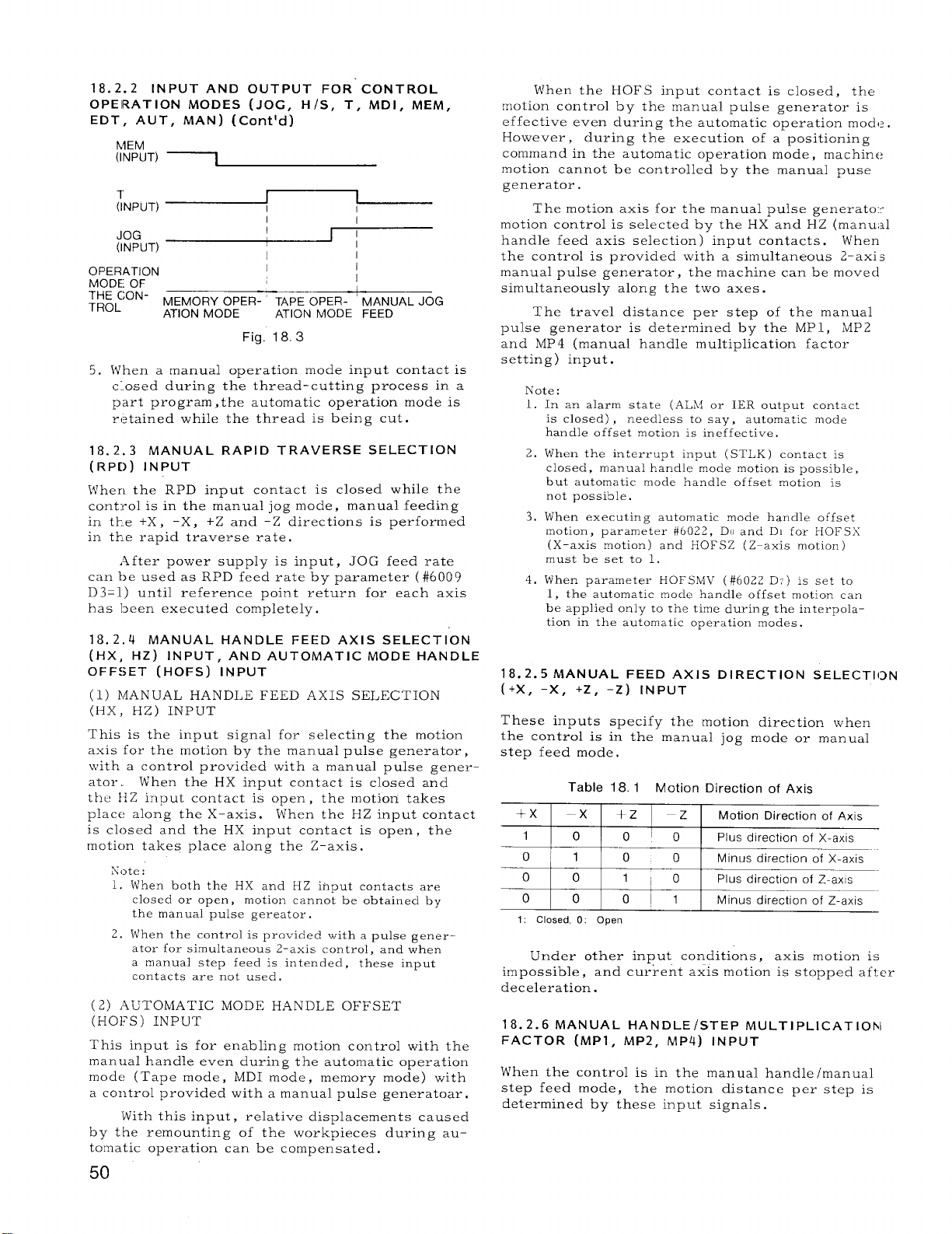
18. 2.2 INPUT AND OUTPUT FOR’ CONTROL
OPERATION MODES (JOG, H/S, T, MDI, MEM,
EDT, AUT, MAN) (Cent’d)
h4EM
(INPUT)
~
(INPUT)
JOG
(INPUT)
OPERATION
MODE OF
::: fON-
~
I
I
I
MEMORY OPER- TAPE OPER- MANUAL JOG
ATION MODE ATION MODE FEED
I
I
I
I
I
I
1
Fig. 18.3
l~hen a manual operation mode input contact is
5.
c.osed during the thread–cutting process in a
part program ,the automatic operation mode is
retained while the thread is being cut.
18. 2.3
MANUAL RAPID TRAVERSE SELECTION
(RP[)) INPUT
1$’hen the RPD input contact is closed while the
cont:rol is in the manual jog mode, manual feeding
in tk.e +X ,
-X, +Z and -Z directions is performed
in the rapid traverse rate,
After power supply is input, JOG feed rate
can be used as RPD feed rate by parameter ( #6009
D3=1) until reference point return for each axis
has been executed completely.
18. 2.4 MANUAL HANDLE FEED AXIS SELECTION
(HX, HZ) INPUT, AND AUTOMATIC MODE HANDLE
OF Ffj ET (HOFS) INPUT
(1) IIJANUAL HANDLE FEED AXIS SELECTION
(13X, HZ) INPUT
This is the input signal for selecting the motion
axis for the motion by the manual pulse generator,
\vith a control provided with a manual pulse gener–
ator,, t~hen the HX input contact is closed and
the llZ input contact is open , the motion takes
place along the X-axis. Ifhen the HZ input contact
is closed and the HX input contact is open , the
motion takes place along the Z–axis.
Note :
1. h’hen both the HX and HZ input contacts are
closed or open, motion cannot be obtained by
the manual pulse gereator .
2. W’hen the control is provided with a pulse generator for simultaneous 2–axis control, and when
a manual step feed is intended , these input
contacts are
not used .
(2) AUTOMATIC MODE HANDLE OFFSET
(HOFS) INPUT
This input is for enabling motion control with the
manual handle even during the automatic operation
mode (Tape mode, MDI mode, memory mode) with
a control provided with a manual pulse generator.
Lvith this input, relative displacements caused
by the remounting of the workplaces during au-
tomatic operation can be compensated.
Ivhen the HOFS input contact is closed, the
motion control by the manual pulse generator is
effective even during the automatic operation mod,? .
However, during the execution of a positioning
command in the automatic operation mode, machine
motion cannot be controlled by the manual puse
generator.
The motion axis for the manual pulse generatoc
motion control is selected by the HX and HZ (manu,~l
handle feed axis selection) input contacts. ~~hen
the control is provided with a simultaneous 2-axis
manual pulse generator , the machine can be movecl
simultaneously along the two axes .
The travel distance per step of the manual
pulse generator is determined by the MP1, MP2
and MP4 (manual handle multiplication factor
setting) input.
Note:
1.
In an alarm state (.ALki or IER output contact
is closed) ,
handle offset motion is ineffective,
2.
IVhen the interrupt input (STLK) contact is
closed, manual handle mode motion is possible,
but automatic mode handle offset motion is
not possible.
l~hen executing automatic mode handle offset
3.
motion, parameter #6022, Dt) and Dl for HOFSX
(X-axis motion) and HOFSZ (Z-axis motion)
must be set to 1,
i~hen ~arameter
4.
1, the automatic mocle handle offset motion can
be applied only to the time during the interpolation in the automatic operation modes.
needless to say, automatic mode
EIOFSIVIV (#60zz D:) is set to
18. 2.5 MANUAL FEED AXIS DIRECTION SELECTION
(+X, -X, +Z, -z) lNpUT
These inputs specify the motion direction when
the control is in the manual jog mode or manual
step feed mode.
Table 18.1 Motion Direction of Axis
1 –Z
+x –x
1
o
o
o
1: Closed, O: Open
+Z
0 0’0
1 0
0
liO
0 0
Motion Direction of Axis
Plus direction of X-axis
0
Minus direction of X-axis
Plus direction of Z-axis
1
I
Minus direction of z-axis
Under other input conditions, axis motion is
impossible , and current axis motion is stopped after
deceleration.
18. 2.6 MANUAL HANDLE/STEP MU LTIPLICATIOhl
FACTOR (MP1, MP2, MP4) INPUT
WThen the control is in the manual handle /manual
step feed mode, the motion distance per step is
determined by these input signals.
50
Page 57

Table 18.2 Manual Handle/Step Multiplication Factor
z
MP1 MP2 MP4 Manual Step Feed
0 0
o
1 0 0
0 [1101
1 1
lor O
1: Closed, O: Open
Note: Only when manual handle multiplication factor is 100 pulses/step,
the control can be usad by any multiplication The multiplication factor
should be set parameter # 6223.
18. 2.7 FEED OVER RI DE/MA NUAL JOGGING SPEED
SELECTION (FV1, FV2, FV 4, FV8, FV16) INPUT,
AND FEED OVERRIDE CANCEL (OVC) INPUT
(1) These input signals are for specifying override
speeds between O and 200% at 10% intervals on
the programmed speeds. In the manual jog mode,
these inputs determine the manual jog feed rates.
FV1oFV2 ~ FV4
+ 00
1
1 1
1
000
1 00
010
1 !1 o
0,01
1 01
g
111
0
1 1 ;0
001
1
01
01
=
1
000
1
01
1 1
001
1
01
1
1 Closed, O: Open
1
1 1
00
0
0
01
1
1 1
1000 pulses/step
0
I 10,000 pulses/step ~ 100 pulses/step
1
Table 18.3
FV8
FV16
o 0
0 0
0 0
0 0
0 0
0 0
0 0
0 0
1
1
1
1
1 0
1 0
1 0
1 0
0 1
0 1
0 1
0 1
0 1
0 1
0 1
0 1
1 1
1
1 1
1
1 1
1 1
1 1
1
10 pulses/step
100 pulses/step
(Automatic
Operation
0
0
0
0
1
1
1
Manual Feed Handle
1 pulse/step
100 pulses/step
Feedrate
Override
Mode)
30 % # 6236
40 % # 6237
50 %
60 %
70 % # 6240
80 %
90 %
100%
150% # 6248
160% # 6249
170% # 6250
180% # 6251
190% # 6252
200 %
o%
Manual Jog
Feedrate
(Manual Oper-
ation Mode)
Parameter
Setting
# 6238
# 6239
# 6241
# 6242
# 6243
# 6253
# 6257
# 6258
# 6259
# 6260
# 6261
# 6262
# 6263
E
# 6264
Note for Table 18.3 :
1. W’hen parameter FOVAB (#6020D5) is set to 1,
inputs FV1, FV2, FV4, FV8, and FV16 become
effective when the contacts are open, and O
and 1 in the table for the input state and feed
override manual jog speeds are reversed.
2.
The manual jog feed rates can be used as the
feed rates for part program by run execution
in the automatic operation modes.
refer to 18.2.14 Dry Run (D RN) Input.
For the thread-cutting in part program execu-
3.
tion in the automatic operation modes , override
is possible only at 100%.
(2) FEED OVERRIDE CANCEL (OVC) INPUT
This is the input for fixing the feedrate override at 100%.
closed,
in the automatic operation modes is locked at the
programmed value,
input conditions.
18. 2.8 RAPID FEE DRATE OVER RI DE(ROV1, ROV2,
ROV4) INPUT
These inputs are for overriding the rapid feed
rates
programs in the automatic operation modes, and
the motion speed in the manual jog mode when
the RT input contact is closed.
4 steps to 6 steps by parameter #6018. D2 = 1,
the feed rate in part program execution
, i.e. , the positioning speed when executing
Input State
ROV1 ROV2
I I I
1
0101
1: Closed, O: Opan
Rapid feedrate override is changed from
ROV1 I ROV2 I ROV4 I X-axis I Z-axis
1
o 0’1
1 1 0 25 % 25 %
o 1 0
1
o o~o
Closed, O: Open
1:
When the OVC input contact is
irrespective of the override
Table 18.4
I
I
# 6280 # 6281
1
SettinQs~eed Settinqspeed
Table 18.5
Input State
oil
0;0 5% 5%
Rapid Feedrate
X-axis
FO (# 6231 Setting sDeed)
I
100% 100%
FO (# 6231 Setting speed)
For details ,
Rapid Feedrate
50 %
10%
Z-axis
50 %
10%
51
Page 58

18. 2.9 REFERENCE POINT RETURN CONTROL
1/0 $51GNALS (ZNR, *DCX, *DCZ)
These are input and output signals for bringing
the machine to the machine reference point upon
the enegization of the control.
(1) GRID METHOD
Reference point is determined by the origin pulse
( 1 pulse /revolution) of the position detector. After
turning on the power supply, when the manual
jog mode is turned on,
point return input contact ZRN is closed, the
direction of axis motion set by parameter ZRNDRX,
ZRNDRZ (#6olo DO, Dl) will result in the reference
point return motion as shown below. ( The same
aPPlle~ to the execution of G 28 in the automatic
operation modes. )
SPEED
I
point once, the return motion, thereafter will be
in the positioning motion to the determined ref–
erenc:e point.
SPEI=D
RAPID TRAVERSE RATE
(#6280, #6281)
//
1
I
~._. ZERO POINT PULSE
When the machine is returned to the reference
RAPID TRAVERSE
(#6280, ti6281)
and the manual reference
APPROACH SPEED 1
(~6310, #6311)
I
II
Fig. 18.4
DECEL LS SIGNAL
(*DCL, * DCZ)
,
1 / \
SPEED
1
Fig. 18.5 Reference Point
Return Motion after First Power ON
However,
(#601. O D4, D5) are set to 1, the same reference
point return motion is obtained also for the 2nd
ti~me onward.
when parameters MZRNHS, AZRNHS
SEQUENCE
(2) X AND Z REFERENCE POINTS (ZPX, ZPZ)
OUTPUT
While the machine is remaining at the reference
point after the reference point return motion or
positioning to the reference point, the ZPX and
ZPZ output contacts are closed.
position is not within f3 pulses from the reference
point due to the use of metric input in the inch
output system or vice versa, the ZPX and ZPZ
output contacts are not closed.
(3) 2ND REFERENCE POINT (2ZPX, 2ZPZ)
OUTPUT
When the machine has been positioned to the 2nd
reference point by the execution of the part pro–,
gram command G30 in the automatic operation mode,
the 2ZPX,
and remain closed as long as the machine remanins
at this point.
by the distance from the reference point as set
by parameters XZP2L, ZZP2L (#6612j #6613) .
18.2.10 MANuAL ABSOLUTE ON/OFF (ABs)
INPUT
During the execution of part programs in the
automatic operation mode, the control stores the
command values in an internal command value
register (command values are displayed on the
1st CRT area),
between the stored value and the coordinate value
in the part program ,
Since the control must also control the current
position , it controls the current values in the
absolute coordinate system (to be displayed in
the 2nd CRT area. The coordinate system is
defined by a coordinate system setting command. )
This input is for determing whether the current
value in the absolute coordinate system is transfer red
to the command value register or not at the start
of the execution of the respective blocks of part
programs in the automatic mode.
When ABS inptu relay is open: Does not transfer.
When ABS input relay is closed: To be trans
ferred,
used.
The motion path after a manual control intervention in the automatic operation mode is changed
as follows by an ABS input.
and 2ZPZ output relays are closed,
The 2nd reference point is defined
and the displacement distance
except when circular interpolation is
If the actual
Page 59

(1) WHEN ABS INPUT RELAY IS OPEN
The motion path after an intervention by manual
axial motion, is the one shifted parallel from the
original path by the distance covered by the manual
motion.
z20.000 FAA;
GO1
X20,000 Z300000
—0 J
Xlo.000 Z40.000
X20.000
Z30.000
Xlo.000
z 20.000
Fig. 18.6
@ When the machine is manually moved
during a block.
X20.000
z 30.000
x 10.000
z 40.000
(3) SUPPLEMENTARY DESCRIPTION
In the following cases, the control transfers current
value in the absolute coordinate system ( coordinate
system displayed in the CRT current value 2nd
area, or the one determined by coordinate system
setting instructions) to the command value register
unconditionally.
. RESET operation:
external reset (ERS) input contact closed
, End of program: Program reset through end of
program (EOP) input contact closing by M02,
M30 execution
. Automatic return to reference point: Execution
of G28 command
After transferring the current value in the
absolute coordinate system to the command value
register, manual axial movement is reflected on
the automatic axial movement even when the ABS
input contact is closed.
When the block @ is searched again by the
RESET operation after axial motions by manual
operation, the following motion takes place.
MDI panel RESET key—on or
x 20.000
Xlo.000
z 20.000
_ Axis motion by manual operation
Fig, 18.7
(2) WHEN ABS INPUT RELAY IS CLOSED.
x 20.000
z 30.000
x 10.000
z 20.000
Fig. 18.8
x 10.000
z 40.000
“ A
x 10.000
z 20.000
Fig, 18.9
18.2.11 SINGLE BLOCK (SBK) INPUT
This input is for executing part programs one block
at a time in the automatic operation mode. With
the control in the automatic operation mode, and
the SBK input contact closed, when an automatic
operation cycle is started, only one block of the
part program is executed, and the machine stops.
When the SBK input contact is closed during the
execution of a part program, the control stops the
machine after the execution of the current block.
For details of the use of single block during
the execution of multiple cycles, user-macro programs, refer to
LX1 (TOE-C 843-7. 20) . “
!!Operator!s Manual for YA SNA C
x 10.000
z 40.000
53
Page 60

18.2.12 OPTIONAL BLOc K DELETE (BDT,
BDT2-BDT9) INPUT
This input is for determining whether data between
“ /“ and
“EOB” in a part program is executed or
neglected when the part program contains “ /. “
Table 18.6
—
BDT INPUT CLOSED
Neglected Data between
“/” or “/1 “ and “EOB”
(End of block)
‘BDT 2 INPUT CLOSED “/2” and “EOB”
‘BDT 4 INPUT CLOSED
$iiEi-
BDT 8 INPUT CLOSED
“-BDT 9 INPUT CLOSED
Note,
1.Data can be neglected only when part programs are executed.
2. Whether data may be neglected or not depends on the state of
18.2,,13 MAc HINE LOCK (MLK) AND
~;::::::::
When storing or processing part programs, this input has no
effect.
the optional block delete input relay when the block containing
“1” in a part program is stored in the buffer. Therefore, when
controlling the optional block delete input relay by an external
circuit with the use of the auxiliary function, take care to set the
input state before the block containing “1” is stored in the buffer,
DISPLAY
Loci< (DLK) INPUT
MACHINE LOCK (MLK) INPUT
(1)
This is the input for preventing the outputting of
control output pulses to the servo unit. While the
MLK input contact is closed, even when the logic
circuit distributes pulses in the automatic and
manual operation modes, the machine does not
move. As the logic circuits distribute pulses, the
current value display changes with the instruc–
tions . If the MLK contact is closed or opened
during the automatic operation of the control, the
operation is not influenced until the start of the
next block, and during manual operation , until
the end of the current motion.
(2) I) ISPLAY LOCK (DLK) INPUT
This input is for preventing the output pulses of
the control from being displayed on the external
current value display. While the DLK input contact
is closed,
even when the machine is controlled
automatically or manually, the external current
value display (DRT. POS 1st display area
“EXTERNAL, “ and external 2-axes current value
display) does not change.
18.2.14 DRY RUN (D RN) INPUT
This input is for changing the feed rates of the
tools during the execution of part programs in
the automatic mode to the rates selected by the
manual continuous feed selection inputs (FV 1, 2,
4, 8 and 16).
While the DRN input contact is closed, the
feedrates during the execution of part programs
in the automatic mode are changed from the pro–
grammed ones to the ones selected by the manual
continuous feed selection inputs.
While the DRN input contact is closed, the
feedrates in part program execution in the automatic
mode are the ones specified by the manual continuous
feed selection input signals, instead of the pro .
grammed one. (However, for thread
cutting,
programmed feedrates remain effective. )
When the DRN input contact is closed or opene~
during the automatic operation of the control, the
following change takes palce.
During mm/rev feeding : No change of feedrate
for the current block.
During mm/min feeding: Feedrate changes even
during the current block.
NOTE
When parameter RPDDRN (#6006 D2) is set to
1.
1, while the DRN input contact is closed, the
feedrate in positioning command is changed to
a manual continuous feedrate.
2.
When parameter SC RDRN’ (#6019 D5S is set to
1, while the DRN input contact is closed, the
feedrate is changed to a manual continuous
feedrate.
18.2.15 CURRENT VALUE STORING (PSR) INPUT
This input is for storing current values in the
control.
When the PST input contact is closed, the
control stores current values (CRT screen POS
display 1st area EXTERNAL) into the internal
memory,
and the LED incorporated in the OF S
key in the MDI FUNCTION area flickers.
Then, it performs the following calculation
on the offsets written by MDI, and stores the result
in the offset memory.
Resetting operation (depressing RESET key
on MD I panel,
or closing external reset input
contact) cancels the current value storing mode
and stops the flickering of the LED.
Page 61

For the details of the usage of the PST input,
refer to 5. 2.3 Measured Workpiece Value Direct
Input in YASNAC LX3 Operator’s Manual (TOEC843-9.20).
18.2.16 PROGRAM RESTART (PRST) INPUT
This input is used when a part program is to be
started again after interruption.
input contact, turn of the memory mode, and
search the sequence No. of program restart by
the NC operator’s panel. The M, S, T codes
present between the leading end of the program
and the searched sequence No. are displayed on
the CRT.
For the details of the usage of the PST input,
refer to “ 5. 2.6 Program Restart” in YASNAC LX3
Operator’s Manual (TOE-C 843-9. 20) .
18.2.17 EDIT LOCK (I NHEDT)
This is the input for preventing the change of the
contents of the stored part program.
INHEDT input contact is closed, the following
operations, among the ones in the program edit
mode, are prohibited.
o Storing part programs by the MEM DATA “IN”
key.
. The change, addition or deletion of part programs
in the m’e-mory with
“ERS” keys.
18.2.18 AUXILIARY
INPUT
This is the input for omitting the M, S , T function
in executing part programs in the automatic
operation mode.
While the AFL input contact is closed, the
control disregards M, S, T instructions of pro-
grams when executing part programs. However,
M code decoded outputs (MOOR, MOIR, M02R,
M30R ) are outputted.
When the AFL input contact is closed or opened
during the execution of part programs, the change
becomes effective from the block subsequent to
the current block.
the EDIT IIALT ~il llIfi S’’ -and
FUNCTION LOCK (AFL)
Close the PRST
While the
While the SRN input contact is closed, manual
jog motion stops as the machine arrives at the
setup point. When the machine is at the setup
point, manual jogging is impossible unless the
SRN input contact is opened.
18.2.20 INTERRUPTION POINT RETURN (CPRN)
INPUT
This is the input for positioning the machine at
the interruption point by manual jogging after
the control was switched over from the automatic
operation mode to the manual operation mode,
and subsequently moved away under manual con–
trol.
While the CPRN input contact is closed,
manual jogging motion stops after arriving at
the interruption point. When the machine is at
the interruption point, manual jogging is impos sible unless the CPRN input contact is opened.
18.2.21 OVERT RAVEL (*+ LX, * -LX, *+ LZ,
*-LZ) INPUTS
These input signals are for signifying the arrival
of the machine slides at their respective stroke
ends. When these overtravel input contacts are
opened ! the machine slides stop motions as shown
in Table 18.7, and close the alarm (ALM) output
contact and, at the same time, display alarm on
the CRT .
Table 18, 7
Manual Opera- Automatic Opera-
tion Mode
“+ LX Motion stop in
Input Opened
*– LX
Input Opened — X direction
*+ LZ
lnDLIt ODened
“– LZ
Input Opened – Z direction
When an overtravel input contact is opened, move
the machine in the reverse direction in the manual
operation mode (manual jogging or manual pulse
generator) to close the contact, and then make
the alarm output and display.
+ X direction
Motion stop in
I
Motion stop in
+ Z direction
Motion stop in
I
tion Mode
Motion stoD of all
I
axes
I
NOTE
With S4-digit instructions analog outputs are output
in accordance with the instructions, even while
the AFL inptu contact is closed.
18.2.19 SETUP POINT RETURN (S RN) INPUT
This is the input for positioning the machine at the
setup point by manual jogging.
NOTE
Even when the overtravel input contacts are opened,
the M code reading output (MF , S code reading
output SF ,
not turned off.
or T codes must be stopped by overtraveling in–
puts, interlock the motion \vith external sequence.
and the T code reading output TF are
If the motion by M codes, S coodes
55
Page 62

18.2.22 MACHINE-READY (MRD) INPUT
This input informs that the external heavy-current
circuit is ready. When MRD input is closed after
closing of Servo Power Input/Output (SVMX)
from the power-on /off unit of the control after
the ;?ower is turned on,
“RD’Y” is displayed on the CRT screen.
When MRD input is opened with the control
being ready, the control is put in the alarm state
(alarm code “ 280” is displayed) , thereby stopping
the operation.
For the turning of power sequence, refer to
“ 10 (CONNECTION WITH POWER INPUT UNIT. “
18.2.23
EMERGENCY STOP ON (XESPS) OUTPUT
the control is ready and
W-hen Emergency-Stop Input ( *TESP) is opend,
*E SE>S output is opend.
18.2.24 ExTERNAL RESET (ERs) lNPuT AND
REs I:T ON (RST1,2) OUTPUT
ERS is the input to reset the control. When ERS
input is closed, the control stops all of its operations,
closing Reset On outputs RST1 and RST2
for c,ne second. The output signals are opened
except for the following.
Table 18.8
Output Signals
Output at ERS Input Closed
AU”r/MAN
zPx/z Pz
2 zPx/2 ZPZ
*ESPS
Previous conditions
keDt
Pol –2
so-1 –2
RS1-l –2
ALM
Output contact is closed for one second while
ERST input contact is closed or is opened.
Contactor kept clos;d unless alarm causing
factor is removed.
S11 –S28
T11 –T28
Dsl –2
SINVA
Previous conditions kept.
RO”I–12
SDOO-15
TLCHI–2
Uoo–15
Note
When ERS
However, memory is rewound, while the tape is not.
Contact closed if any of selected, group of
tools reaches end of life.
Previous conditions kept.
inputis closed,the control is put in the label skip state.
18.2.25 INTERLOCK (STLK) INPUT
This input stops the spindle travel in the automatic
operation mode. When “ STLK” input is closed
during the spindle travel in the automatic operation mode,
only the spindle travel is stopped with
the automatic operation being activated (” STL”
output is in the closed state) .
When “STLK”
input is opened again, the spindle travel is
resumed.
“STLK” input does not affect the M, S , and
T commands in both manual and automatic operation modes.
18.2.26 ALARM (ALM) AND INPUT ERRoR (IER)
OUTPUTS AND EXTERNAL ERROR DETECT
(E RRo, l)
lNpuTs
(1) ALARM (ALM) AND INPUT ERROR (IER)
OUTPUTS
These outputs inform that the control is in the
alarm state.
IER :
This output is closed on detection of an
alarm caused by the information from the part
program or the input device. (Alarm codes “ 010’1
through “129. ‘1)
ALM : This output is closed on detection of any
alarm other than the above. (However , the alarm
for the fault of the logic circuitry in the control
is not included. )
These outputs are opened again when the cause
of the detected alarm has been removed and
RESET operation is performed.
(2) EXTERNAL ERROR DETECT (ERRO, ERR1)
INPUTS
These inputs put the control in the alarm state
from the outside .
ERRO:
displays alarm code
When this input is closed, the control
II180!I and is put in the alarm
state. If this input is closed during the execution
of the part program in the automatic operation
mode,
the execution is stops on completion of
the block being executed.
ERR1:
When this input is closed, the control
displays alarm code “400” and is put in the alarm
state . If this input is closed during the execution
of the part program in the automatic operation
mode , the tool travel is immediately slowed do~vn
and stopped.
18.2.27 RAPID THREADING PULL-OUT (CDZ)
INPUT AND ERROR DETECT-ON (SMZ) INPUT
(1) RAPID THREADING PULL-OUT (CDZ) INPUT
This input determines whether rapid threading
pull-out is performed or not in the execution of
G92 (thread cutting cycle) or G76 (composite
thread cutting cycle) . When CDZ input is closed,
the rapid threading pull–out is performed; when
this input is open, it is not performed,
The control determines by the CDZ input
whether rapid threading pull–out is performed
or not at the start of a thread cutting cycle.
To open/close CDZ input by such a command as
M, add the delay time of the input circuit processing and set the state of CDZ input to the
start of thread cutting cycle.
56
Page 63

(2) ERROR DETECT GN (SMZ) INPUT
This input determines whether “Error Detect On”
condition is added to the end conditions for the
feed in the automatic operation mode.
ItError Detect On” :
Due to the servo system delay, during traveling,
the position detected by the position detector
follows ,
cuit with a delay.
and the detected position are found under the
values set in parameters XPSET and ZPSET (#6056
and #6057), it is called in the “Error Detect On”
state.
the position designated by the logic cir-
When the designated position.
When SMZ input is closed, “ Error Detect On”
condition is added to the feed end conditions in
the automatic operation mode. When this input
is open, this condition is not added.
SMZ input does not affect any positioning
commands.
(With each positioning command except
G06 (Error Detect Off Positioning) , “Error Detect
On” condition is added to the end conditions. )
These are outputs for the M, S, and T commands
specified by the part program at its execution
in the automatic operation mode. Ifanyof M, S,
and T commands is found at the execution of the
part program in the automatic operation mode,
the control outputs it in a BCD code according
to the value that follows the detected command
(M = 2 digits/3 digits, S = 2 digits, T = 2 digits) ,
Then, after the elapse of the time set in
parameter MSTF (#6220) , the M, S, and T code
reading outputs are closed.
NOTE
1!
h’ith the S4 digit
provided, disabling the S code output and the
S-code read output.
M commands (M9 O throu~h M109) for logic circuit
2.
processing: With the ~ commands (T-~I~AA ,
T51AA through T80AA, T90AA, TD~90
through TDD95, and T UU99) , the M/T code
ouput and ‘the M]T code reading output are not
provided.
command, analog output is
18.2.28 X-AXIS MIRROR IMAGE (MIX) INPUT
This input inverts the X–axis traveling direction
in the automatic operation mode. When an automatic
activation is performed with MIX input closed,
the X-axis traveling direction by the part program
is made opposite to the specified direction. When
klIX input is closed then opened during the execution of the part program , it is made valid for
the commands after the satisfaction of the follow.
ing two conditions:
(1) Compensation cancelled.
(2) Out of automatic operation,
MIX input does not affect the X-axis travel
in the manual operation mode.
18.2.29 M, S, AND T CODES (Mll THROUGH
M38, S11 THROUGH S28, Tll THROUGH T28,
MF, SF, TF, FIN) lNPUTS/OUTPUTS
(1) M, S, AND T CODES OUTPUT AND M, S,
AND T CODE READING OUTPUTS
Table 18.9
M code output
S code output
T code output
M codereadingoutput
Mll, M12, M14, M18, M21, M22, M24,
M28, M31, M32, M34, M38
S11, S12, S14, S18, S21, S22, S24, S28
Tll, T12, T14, T18, T21, T22, T24, T28
MF
S code readingoutput SF
T code readingoutput TF
(2) M DECODE (MOOR, MOIR, M02R, AND M30R)
OUTPUT
When any of M commands “MOO,” “MO1, ” “M02, ”
and “M30” is executed, the corresponding decoded output “MOOR, “ “MOIR, ” “M02R, ” or
!)M30R!1 is outputted in addition to the M code
output and the M code reading’ output.
NOTE
When an M command for decoded output and a
move command are specified in the same block,
the M code output is provided at the start of the
block, while the decoded output is provided after
completion of the move command.
(3) M, S, AND T FUNCTIONS COMPLETION
(FIN) INPUTS
These inputs give the completion of M, S, and T
commands to the control.
When FIN input is
closed while the M, S, and T code reading (MF,
SF, and TF) outputs are closed, they are opened.
If FIN input is opened again after making sure
of their opening, the control assumes that the
M, S, or T command has been completed, starting
the operation of the next step.
NOTE
For the S4-digit command, FIN input need not
1.
be closed.
2.
When FIN input is closed then opened, the M
code output and the M decoded output are all
opened, but the S code and T code outputs
remain without change .
57
Page 64

18.2,29 M,S, AND T CODES (Mll THROUGH M38,
sll “THROUGH S28, Tll THROUGH T28, MF, SF,
TF, FIN) INPUTS/OUTPUTS (Cent’d)
(4) CUIME CHART OF M, S, AND T SIGNALS
TO NEXT
STEP
~OIMMAND
I
n
L-
.—— -
/ ::JEXT
,
1
//
,,
“FIN”
I
INPUT
SIT
OUTPUT
Sll”
COMMAND OUTpUT
SIT CODE
~ READING
“FIN”
INPUT
CODE~
l)
\\!
I I
,,
,,
1
11
I
+1-
PARAMETER *6220
“MSTF” SETTING
TIME
Fig, 18.10
move command and an M , S , or T command are
If a
specified in the same block, the move operation
and the M, S, or T operation are executed
simulataneously.
TO NEXT
STEP
18.2.31 TRAVEL ON (O P1 ,2) AND THREAD
cuTTING ON (T Hcl ,2) OUTPUTS
(1)
TRAVEL ON (OP1,2) OUTPUTS
With these outputs ,
tool is traveling during the execution of a part
program in the automatic operation mode. These
outputs are closed in any of the following situa–
tions:
. During the execution of a move command.
. In the state in which a move command is discon-
tinued by the interrupt (STLK) input or the
FEEDHOLD (*SP) input.
(2) THREAD CUTTING ON (THC1,2) OUTPUTS
With these outputs, the control informs that threai
cutting is being performed during the execution
of part program in the automatic operation mode.
These outputs are closed during thread cutting.
the control informs that the
18.2.32 END-OF-PROGRAM (EOP) INPUT, REWIND
(RWD) INPUT AND REWIND ON (RwDsl,2)ouTpu-rs
(1) END-OF-PROGRAM (EOP) AND REWIND (RWD)
INPUTS
With these outputs, the controller determines what
processing is to be performed at completion of
an M02 or M30 command.
The control performs
the following processing, depending on the state
of EOP and ~WD
FIN for an M02R
inputs, when completion input
or M30R commands is opened and
then closed:
In general,
output and RWD
EOP input is connected to M02R
input, to M30R output,
M CODE
READ-IN
SIGNAL ‘
\
/
/1
“FIN” INPUT ~
Fig. 18.11
18.2.30 pOsi TIONi NG COMPLETION (DEN1 ,2)
OUTPUTS
These outputs inform the completion of a move
command when an M, S , or T command and the
move command have been specified in the same
block at the execution of a part program in the
automatic operation mode.
The block in which an M, S, or T command
and a move command are specified at the same
time is executed, if the M, S , or T command is
not completed at the termination of the move
command, positioning completion outputs DEN 1
and DEN2 are closed.
When FIN input is closed then opened and the
M, S , or T command is completed, the positioning
completion outputs are opened.
Table 18.10
EOP I RWD I Function
1 1
i
] The control IS at standby after rewinding part
1
[ programs and resetting programs
The control is at standby after resetting pro-
The control !s at standby after re;inding part
=
1: Closed, O: Open
Note:
1.2.Program reset provides the same effects as
with depressing of RESET key on MD I panel
(ERs) input.
the NC memory rewind operation is not perfomed.
For details of the reset operation by closing
ERS input, refer to 18.2.24 “EXTERNAL RESET
(ERS) INPUT.’!
When a program reset operation is perfomed,
Reset On output RST1 and RST2 are closed
for one second.
In the program reset, however,
—
Page 65

(2) REWIND ON (RWDS1,2) OUTPUTS
With these outputs, the control informs that the
part program is being rewound.
If the part
program is rewound by RWD input for an M02 or
M30 command, RWDS1 and RWDS 2 are closed during the rewinding operation.
18.2.35 S4-DIGIT COMMANDS (DAS, SCSI, GR1
THROUGH GR4, SINV, AND SINVA) lNPUTS/
OUTPUTS
These signals are used to determine the speed
of the spindle motor when the conrol is in the
state of S Command 4–Digit Analog output.
NOTE
To use these outputs, set parameter RWDOUT
(#6007, D4) to “1. ” Otherwise, they are not
provided.
18.2.33 DISPLAY RESET (D RSX, DRSZ) INPUTS
These inputs set the external 2-axis current value
display and the current value display on the
Operator’s panel CRT to “O.” When “DRSX” txaxis display reset) or
reset) is closed,
II()!!is set to the external z–axis
IIDRS ZII (z–axis display
current value display and the current value di=
play on the operator’s panel CRT (the first screen
“EXTERNAL” ) .
18.2.34 EXTERNAL STORE, MATCH, AND
OUTPUT (E IN, EVER, AND EOUT) INPUTS
These inputs are used to perform store, match,
and output operations on the NC memory of the
control from outside.
If these inputs are closed when the control
is in the program edit mode and Edit Output On
(EDTS ) output is closed, the following operations
take place:
EIN input is closed:
The part program is stored in the NC memeory.
EVER input is closed:
The part program is matched against the NC memory.
EOUT is closed:
The contents of the NC memory are outputted.
While a store, match,
or output operation is
performed, the In-Edit (EDTS) output is closed.
GR1 through GR4 are used to enter into the
control state of the gear range between the spindle
and the spindle motor to determine the spindle
motor speed by the spindle speed specified in the
part program.
SINV input inverts the polarity of the analog
output at the time of S Command 4–Digit Analog
output .
While the polarity is inverted, SINVA signal
is outputted.
(1) S4-DIGIT COMMAND ANALOG (GAS, SGS1)
OUTPUT
Analog voltage (-10V to OV to +1OV) is outputted
as follows by the spindle motor speed command
and GR1 through GR4:
—.—
The output when
;
l!GRIII input is closed.
( Set the spindle motor maximum speed at
gear range
“GR1” to parameter GRIREV:
#6271. )
—.-— ;
The output when
11GR2!! input is closed.
(Set the spindle motor maximum speed at
gear range
“ GR2° to parameter GR2REV:
#6272. )
—...— .
The output when
9
11GR3!1 input is closed.
( Set the spindle motor maximum speed at
range 11GR311 to parameter GR3REV:
gear
#6273. ) -
—.. ..—
The output when “GR4” input is closed.
;
(Set the- spindle motor max~mum speed at
range 11GR41t to parameter GR4REV:
gear
#6274. )
SPINDLE MOTOR
SPEED COMMAND OUTPUT
NOTE
The 1/0 equipment for the store and match operations depends on setting ID VCEO, 1 and ODVCEO,
1 (#6003) .
—-— : OUTPUT WITH “GR 1“ INPUT CLOSE
—--— OUTPUT WITH “GR 2“ INPUT CLOSE
—---— : OUTPUT WITH “GR 3“ INPUT CLOSE
—.. ..—
: OUTPUT WITH “GR4 INPUT CLOSE
Fig. 18.12
59
Page 66

18.2.35 s4-DIGT coMMANDs (DAS, scsl. GR1
THRC)UGH GR4, SINV, AND SIN VA) -
lNPUTS/OUTPUTS (Cent’d)
0-!.,-, r ------
arl NuLr Mu 1 UP.
SPEED OUTPUT
+1OV
(2) TIME CHART OF ANALOG VOLTAGE OUT-
PIJT, SINV INPUT, AND SINVA OUTPUT FOR
SPINDLE MOTOR SPEED
SINV INPUT
SINVA OUTPUT
‘+
;1
II
100 ms
klAX
Fig, 18, 13
(3) SPINDLE MAXIMUM/MINIMUM SPEED CLAMP
The spindle maximum/minimum speed at each gear
range may be set using the following parameters:
Table 18.11
Parameter Function
MACGR1
( # 6266)
1
Spindle maximum speed when
“GRI” input is closed.
MACGR2 Spindle maximum speed when
( # 6267)
T
MACGR3
(# 6268)
“GR2” input is closed.
Spindle maximum speed when
‘(GR3° input is closed.
I
No. in Fig.
below
v
VI
w
MACGR4 Spindle maximum speed when
( # 6269)
MICGR1
( # 6276)
+
MICGR2
( d 6277)
MICGR3
( 8 6278)
MICGR4
( # 6279)
“GR4” input is closed.
Spindle minimum speed when
“GR1” input is closed.
I
Spindle minimum speed when
“GR2” input is closed.
I
Spindle minimum speed when
“GR3” input is closed.
I
Spindle minimum speed when
“GR4” input is closed.
I
I
II
H
N
I
OUTPU
FOR
SINV
INPUT
Ov
::;Pu-
SINV
INPUT
–1OV
Fig. 18, 14
Note
1,
The spindle motor speed command output is
obtained from the following relation:
(Spindle speed command) x (10 V)
(Spindle gear range spindle maximum speed
determined by GR1 through GR4 inputs: param-
eters #6271 through #6274)
With the spindle motor speed command analog
2.
output, the polarity may be inverted by processing M03 (spindle fo\~,ard rotation) or M04
(spindle reverse rotation) within the control
by using parameter SDASGN1 or SDASGN2
(#6006, D6 or D7).
Table 18.12
SDASGN1 SDASGN2
( S 6006, Da) (#6006, D,)
o
~ 0 i ‘----------
0
1
–---i
When SINV input is closed, the above polarities
are inverted.
When spindle S Command Stop (SSTP) input
3,
is closed,
earlier may be outputted for the spindle motor
speed command. For details, refer to “SPINDLE
S COMMAND STOP (SSTP) INPUT . “
when two or more of GR1 through GR4 inputs
4,
are closed or not closed , the control determines
the gear ranges as follows:
o
I
1
1
a value other than those described
M 03 M 04
OUtDUt outDut
I + +
+
—
i---
GR4REV
)~NDLE
SPEED
COMMAND
.-.
F
..
+
The following diagram shows an example of the
S4-digit analog outputs when the spindle maximum/
minimum speeds are clamped by these parameters:
Table 18.13
GR1 Input
GR2 Input GR3 Input ~GR4 Input
o
1
1 0
0
1
1
0
1
o
1
0
1
Ii
1~1
o~o 1
1
11
I , I
0
I o I
0 0
0 0
1-0
.fl- .. .. . 0 [ Gear range 2
0 1 Gear range 2
o
I
1 1 Gear range 3
1’1
o
1
I Gear range 1
I Gear ranoe 1
Gear Range
Gear range 1
Gear range 1
0 1111!1 I Gear ranae 2
I
1
111111
0: Input open, 1: Input
closed
Gear range 1
Page 67

-7 m., .
supplementary hxplana~lon
Constant surface speed control and S4-digit
command output:
When constant surface speed control ( G96) is
specified by the part program at its execution in
the automatic operation mode, the output is’var–
,ied every 100 ms according to the following relation
during a cutting operation:
(Surface speed by S command) ~
(X-axis current value) X (~)
(Spindle gear range max. speed determined
by GR1 to GR4 inputs)
Time Chart Example
S OUT-‘
PUT ~ ~---
I
––––––-t–—~
CUTTING
EXECUTING COMMAND
POSITIONING POSl - CUTTING
NO. 1 NO. 2
TIONING EXECUTION
Fig. 18, 15
Setting parameter POSG96 (#6020, DO) to “1” enables
the control to perform the constant surface speed
control also on the positioning command. (However,
only the spindle speed obtained by the coordinate
value of the positioning end point is outputted. )
18.2.36 SPINDLE S COMMAND “O” (SST P), GEAR
SHIFT ON (GRS) INPUT, AND SPINDLE CONSTANT
SPEED (G SC) INPUT
These inputs are used to make the S4-digit command
analog output provide the outputs other than the
part program S command. When SSTP input is
closed, the spindle motor speed command output
based on the spindle speed specified in the part
program is stopped.
If GRS input is closed in this state, the voltage
to set to parameter GRSREV (#6270) is outputted.
If GSC input is closed, the spindle motor speed
command voltage is outputted which corresponds
to the spindle speed to be set to parameter GSCREV
(#6275) by the spindle gear range input.
-,-,-.”..
-,
Iaule IO. 14
SSTP GRS GSC S4-digit Command
Input Input
o 0
Input
0
Analog Voltage
Voltage corresponding to spindle
speed commanded by NC pro-
=029.
011111
110101
1
Voltage corresponding to param-
0
I
1
I
eter GSCREV.
I
Ov
1 I 1 I O I Parameter GRSREV setting value.
111111
O: Contact open, 1 Contact closed
Note
1,
It is possible to make the analog outputs for
SSTP, GRS, and GSC inputs negative by the
S4-digit analog output invert (SINV) input.
2,
The period of time bet\veen the setting of SSTP,
GRS, or GSC input and the catching-up of
the analog voltage value is shorter than 100
ms.
3.
Setting parameter SSTPAB (#6020, D4) to 1
enables the control to provide ‘! *SSTP!! input,
Ov
18.2.37 SPINDLE SPEED REACHED (sAGR) INPUT
This input is used to inform , in the case of the
S4–digit command, that the spindle speed has
reached the specified value at the start of cutting
at the execution of the part program in the auto–
matic operation mode.
At the start of cutting
( when switching from a positioning command to a
cutting command takes place) , the control delays
the time by the value specified in parameter SAGRT
(#6224) , makes sure that SAGR input is closed, and
starts cutting.
NOTE
To perform the above operation by SAGR input,
1.
set parameter SAGRCH (#6006, D4) to “1. ”
If it is set to [IO, “ SAGR input is ignored.
2.
In G96 mode, SAGR input is checked every time
the switching from a positioning command to
a cutting command takes place.
SAGR input
when the spindle speed is different between
the positioning start and end times.
is checked at the switching only
In G97 mode,
18.2.
38 SPINDLE SPEED OVERRIDE (SPA, SPB,
SPC, SPD AND SPE) INPUTS
These inputs are used, in the case of the S4-digit
command, to override the S command in a range
of 50% to 120% at the execution of the part program
in the automatic operation mode,
61
Page 68

18.2.38 SPINDLE SPEED OVERRIDE (SPA, SPB,
SPC, SPD AND SPE) INPUTS (Cent’d)
Table 18.15
‘s F)A
SPB
Input Input Input
1
() 1
1
o 1 0
1 1 0
1
()
o 0
1
1
Closed, O Open
0 0
o 0
0
SPC
1 50 %
I
1 60 %
I I
I I
I I
I I
Override to S Command
I
1
1
70 %
80 %
90 %
100%
110%
120%
(override is specified to S command within
10% to 200% range by parameter #6018 D1.
A’ote: The input /output value is a signed binary
16-bit.
as follows: -32767 to O to +32768, -1OV to O to
+10 v
The relationship with analog voltages is
NOTE
The primary purpose of this function is to
control the S4–digit command by the sequence l-
built in the control.
not be used for other purposes unless especially required.
This function should
18.2.40 EXTERNAL WORK NUMBER SEARCH A
(WN1, WN2, WN4, WN8, AND WN16) INPUTS
This is a function to select the program by the
program number specified by external input from
the part programs stoeed in the part program
memory of the equipment.
(1) To use this external work number search A ,
assign the program number as follows :
SPA
o
0
0
1
1
0
0
1
1
0
0
1
1
1
1
0
0
0
0
1
1
SPB
o
0
1
1
1
1
1
1
0
0
0
0
0
0
1
1
1
1
0
0
Closed, O
Input
SPC
o
1
1
1
1
1
0
0
0
0
1
1
1
0
0
0
0
0
0
0
Open
3PD
-L
1
1
1
1
0
0
0
0
0
0
0
0
1
1
1
1
1
oil
01
01
SPE
—
:1
Override to S Command
o
0
0
0
0
0
0
0
0
0
0
0
0
0
0
0
10%
20 %
30 %
40 %
50 %
60 %
70 %
80 %
90 %
100%
110%
120%
130%
140%
150%
160%
170%
180 %
190%
200 %
18.2.39 54-DIGIT COMMAND EXTERNAL OUTPUTS
(sDOOTti ROuGt-I sDo15) AND S4-DIGIT EXTERNAL
INPUTS (SDIO THROUGH SD115)
0 ❑D AA
Work Number (01 to 31)
F
The work number search timing is as follows (provided that the external input (WN 1 to WN 16) is
not “00”) :
a. A reset operation. (When RESET key is pressed,
or the external reset input or EOP input is turned
on.
)
b. When CYCLE START key is pressed in the
memory mode and the label skip on state.
(2) The relationship between external inputs 1$’N1
through WN16 and program numbers is as shown
in Table 18.16.
Any
These inputs and outputs are used, when the
control is of S command 4–digit, to output the
results of the operation by the S command in the
part program to the outside and perform the actual
S4-digit command analog output according to the
inputs from the outside.
(1) S4-DIGIT COMMAND ANALOG OUTPUT
. Output of operation results to outside:
SDOO through SD015
. Inputs from outside to output analog voltage
to DAS and SGS1: SDIO through SD115
62
Page 69

Table 18.16
Program No.
❑005
IJO 06 0
❑007 I 1
❑009
——
❑010
WN1 WN2 I WN4
1
I
110 0
0
Input State
0
1
Ill lolo
1
1 0 0
1
0
WN8 WN16
❑011 1 1 0
❑012 o 0
❑D13 1
0
1 ,1
111
❑014101111’ 110
❑D1511111,
—
i
❑016 o 0
1
1 1
0,0
I
❑01711/0 Ololt
❑0181011,0
❑O19I1I1O
❑024 o 0’0
❑U25 1
❑026
o
0’0
1
io
I
I
❑0271111101111
❑029110
❑030 I o
I
1111111
11111
I
❑D311111111111
1: Closed, O: Open
Note:
1.
WN 1 through WN16 inputs are disregarded at the
start of a part program in other than memory and
running modes.
when an automatic run is activated in the label
skip state ( “LSK” is being displayed on the CRT
screen) .
2.
The program number selection by a reset opera-
tion is perfomed independently of the running
mode.
3,
When WN 1 through WN 16 inputs are all open, the
program number selection is not performed.
4.
If the part program memory of the control contains
two or more part programs which have part program
numbers 01
WN 16, the program stored nearest the memory
beginning is selected.
5.
The program numbers for which this “search func-
tion is valid are O
6.
If the specified program number is not found after
a search operatiori,
7.
When this work number search A function is per-
formed, FUNCTION is automatically changed to
PROG.
The start of a part program is
through 31 specified by WN 1 through
\
❑0 01 through O ❑n 31.
error 111341’ is caused.
0 0
1
1
1
110
011
011
1 1
1 1
1
11
18.2.41 TIME COUNT (EXTC) INpu T (oPTi ONAL)
This input makes the control count the time. The
control accumulates the time in which EXTC input
is closed and displays the result in the bottom
of “OPERATION TIME DISPLAY , “ which is on page
3 of “ALM” function on the operator’s station CRT,
(Operating time display “ EXTERNAL ‘t is optional. )
The time display is reset by pressing “4” key
then ~]
operation is performed, the time display is retained
after such an operation as power–on,
18.2.42 SPINDLE INDEXING FUNCTION (Si Dl -
0
0
0
0
0
1
S1D12) lNPUT/OUTPUT
This input/output is used perform the spindle
indexing function which stops the spindle at the
desired position by controlling the S4-digit analog
output by the pulse from the spindle pulse genera-
tor. “
(1) INPUT SIGNALS
0 SID1 through SID12:
Binary 12-bit (O to 4095) input signals to specify
the spindle stop position. Each signal corresponds
to the pulse (4096 pulses/rev) from the spindle
pulse generator. Usually, the stop position
corresponds to the number of pulses entered
by SID1 to SID12 from C-phase pulse (1 pulse/
rev) of the spindle pulse generator ,
Note:
the control to shift the stop position by the
number of pulses set from C–phase pulse to
this parameter.
‘ SIDX:
The input signal to request the control for a
spindle indexing operation.
closed while the spindle is rotating, the speed
command to perform indexing is output ,and the
spindle indexing operation is started.
After the completion of the indexing opera-
tion, the spindle speed command analog output
remains a spindle positioning command unless
this input is turned ‘off.
control continue the indexing operation ,
o SIDXI and SIDXINC :
SIDXI (spindle indexing restart input) and
SIDXINC (spindle stop position designate incremental input) are the inputs for the repetitive
spindle indexing sequence.
to (6) INPUTS FOR SPINDLE INDEXING EXTENTION FUNCTION.
(2) OUTPUT SIGNALS
“ SIDXO:
This output goes on when the control is per-
forming a spindle indexing operation ( during
the output of creep speed command or spindle
positioning command) .
key by the MDI. Until this reset
Use of parameter SIDREF (#6342) enables
If this input is
Thereby making the
For details , refer
63
Page 70

18.2.42 SPINDLE INDEXING FUNCTION (SIDlSID12) iNPu T/o UT PUT (Cent’d)
. SI13XA:
This signal indicates the completion of a spindle
indexing operation.
position is in the range between the position
set in parameter SPSET (#6058) and the position
designated by SID1 to SID12,
It is on while the spindle
SPINDLE INDEX
M CODE
SPINDLE INDEX
POSITION INPUT
(SIDI-SID 12) \ /
SPINDEL INDEX
REQUEST INPUT
(SIDX)
SPINDLE INDEX
OUTPUT (SIDXO)
SPINDLE INDEX
COMPLETION
ouTpuT (siDxA)
M, S, T FUNCTION
COMPLETION
INPUT (FIN)
SPINDLE
ROTATION
SIGNAL
;;;NE;LE
ANALOG
OUTPUT
\ 1
/
I
J
J
+
o
i
(3) SPINDLE INDEX TIME CHART
. Spindle index by M-code at spindle stop (Spindle
positioning is released after spindle index is
completed. ) See Fig. 18.16.
. Spindle index by M code at spindle forward
operation (Spindle positioning is continued until
next spindle speed command after spindle index.
is completed. ) See Fig. 18.17.
I
I
/~q
/,\ i
1
I
I
1 v
lln–
1,
\!
I
\
i
1
/’
— ———
I SPINDLE+
POSiTlONING
SPINDLE INDEXING
SPINDLE INDEX
REQUEST INPUT (SIDX)
Ezpsoxti=
M, S, T FUNCTION
COMPLETE INPUT (FIN)
SPINDLE
SPEED ANA-~~ANALOG
LOG OUTPUT OUTPUT
+-’
1[
BY S
COMMAND
I
I
I
I
!
SPINDLE INDEX
START SPEED
Fig. 18.16
CREEP SPEED
COMMAND
Fig. 18.17
II
(
VA
M CODE FOR
SPINDLE SPEED-f
COMMAND
1’
I ~
!)
SPINDLE INDEX
POSITIONING
. ,(
t—
SPINDLE
MOTOR
SPEED
Page 71

(4) PARAMETERS FOR SPINDLE INDEXING AND
DETAILED sPINDLE INDEXING
Table 18.17
No.
Pulse width of index completion
Bits setting for output satura-
~~
# 6076
(SSVER)
~
—
86343
(SIDRV1)
ti 6344
(SIDCRP)
# 6227
(KPS)
Note: 1 pulse = 0.0886
SPINOLE
SPEEO
COMMA~O
‘~i
Servo alarm area settingfof
spindle drive
Timer setting to confirm the
Spindle index reference point
1
Spindle index speed command
Spindle index creep speed
Icommand
1
Position loop gain
s COMMANO
SPEEO
Detailed Function of
Spindle Indexing
(
SPINOLE SPEED
360”
4096 pulses
Setting
1=1 pulse
Refer to
parameter table.
Refer to
parameter table.
l=8ms
1=1 pulse
1=500 pps
1=500 pps
Set 1024.
)
~~:~::~,)k“’’’TAR;;;,,E
lNDE~TART- ‘- ‘– ‘--– ( “’’’” ~
REQUEST fl—
INPUT
(SIDX)
,NOEX I WY
poS1’,ON~- ‘-
INPUT
TIMER SETTING
TO CONFIRM
~;~pSPINOLE
+.
L~
II
INOEX COMPLETION OUTPUT
(SIOXA)
L. -—~
INOEX POSITION DESIGNATION (S101 -S1012)
Fig. 18.18 Detailed Spindle Indexing
INOEX COMPLETION
oUTPUT
A
~ t Y:J:::::WPLE
SPINDLE PG
PULSE
SPINOLE PG
ORIGIN PULSE
ANGLE
(5) DISPLAY OF SPINDLE INDEXING FUNCTION
When the control contains the spindle indexing
option, the following dispaly is made under
heading
SPINDLE COUNTER on page 8 of the POSITION
display on CRT screen:
During a spindle indexing operation ( SIDXO
output is on) , the number of pulses from the
spindle pulse generator is displayed.
/
SPINDLE COUNTER
PULSE COUNTER FOR SPINDLE INDEX
01234 N1234
PULSE
12345
“—————___—_——
W7hen a spindle indexing operation is not per-
formed (SIDXO output is off) , the spindle speed
(obtained by converting the number of pulses
from the spindle pulse generator) is displayed.
SPINDLE COUNTER
SPINDLE SPEED
(
I
01234 N1234
RPM
12345
Page 72

18.1! .42 SPINDLE INDEXING FUNCTION (S IDl -
SID12) lNPUT/OUTPUT (Cent’d)
(6) SPINDLE INDEXING EXTENSION FUNCTION
INPIJT
The control provides the following two inputs to
process various spindle indexing sequence made
available by application of the spindle indexing
function described previously.
. SI:3XI :
Spindle indexing restart input. If this input
is closed with Spindle Indeking On (SIDXO)
output on, the control stops the spindle indexing operation and turns the SIDXO output
off. While the indexing operation is discontinued ,
the spindle speed command analog output becomes
the spindle indexing start speed command.
When this input is turned off in this state, the
control restarts the spindle indexing operation.
SPINDLE lNDEX M CODE
SPINDLE INDEX
POSITION lNPUT(SIDI-SID12)
SPINDLE INDEX
REQUEST INPUT
\
\
J
- SIDXING :
Spindle indexing position incremental input.
This input is used to designate an incremental
position of the spindle indexing position input
(SID1 to SID12) from its previously designated
position.
The use of this input enables the control
to rotate the spindle from the current indexin~
position to the next indexing position without
a full rotation, However, this input is invalid
when the spindle indexing operation is first made
after rotating the spindle in non–indexing opera–
tion or when the spindle indexing operation is
first made after the power–on operation.
‘ Example of Spindle Indexing Time Chart using
Spindle Indexing Extention Input:
(i) Restart the spindle index if spindle ~ndex
is not completed, the specified time after spindle
indexing (Fig. 18.19) .
SPINDI
‘:E’*Z
COMPL-,, -,.
ouTPuT (stDxA)
SPINDLE INDEX
RESTART INPUT
(SIDXI)
SPINDLE INDEX
COMMAND
ANALOG OUTPUT
o
II
;1
II \/
~
,
I
CREEP SPEED
COMMAND
1
SPINDLE
INDEX
SPEED
COMMAND
Fig. 18, 19
II I
II
!
1
I
66
Page 73

(ii) Spindle indexing at A position 180° from
the indexed position after spindle indexing and
mechanical clamp and machining. See Fig. 18.20.
M CODE FOR
SPINOLE
INDEX AND
MECHANICAL
Ai4D (< DINlnl C lNlnCY 1800) AND CLAMP
SPINDLE INDEX
POSITION INPUT
(SIDI-SID12)
SPINDLE INDEX
REQUEST INPUT (SIDX) ‘,,
SPINDLE INDEX I
OUTPUT (SIDXO)
SPINDLE INDEX
COMPLETION OUTPUT
(SIDXA)
M, FUNCTION
C.OMPLETE SIGNAL(FIN)
SPINDLE ROTATION
SIGNAL (EXTERNAL
SEQUENCE PROCESSING)
SPINDLE MECHANICAL
CLAMP SIGNAL
(EXTERNAL SEQUENCE
PROCESSING)
SPINDLE MECHANICAL
CLAMP CHECK SIGNAL
(EXTERNAL SEQUENCE
PROCESSING)
PI
2,,
‘“t
\ c: -
\
1
I
M CODE FOR MECHANICAL UNCLAMP
1
I
[
1
I
II
I
II
SPINDLE
COMMAND ,..
VOLTAGE
.J 1
Note:
1. The s~indle indexing function is available
only ;hen the contr;l has the S command
4-digit analog output specification. The
polarity of S 4-digit analog output should
be externally determined by SINV input.
2.
To make a spindle index from the spindle
reverse rotating state, keep SINV input
on while the spindle indexing request in–
put (SIDX) is on.
3.
When an incremental spindle indexing
operatiOn is perfOmed by turning SIDXINC
input on with SINV input being on, the
direction of the increment specified by SID 1
to SID 12 is reversed.
I
I
A-, B-PHASE
PULSES
C-PHASE PULSE
REFERENCE
PULSE OF
FORWARD I
DIRECTION I
-
1 I I I I I I I
I
I
I
SPINDLE
INDEX
sPFFn
-. ---
COMMAND
I
I
1
1
~~i~
CREEP SPEED
COMMAND
Fig. 18.20
I
CREEP
<
3NDARY PROCESS-
‘--
SEC(
,., - !
ll~u tiITHOUT SPINDLE
ROTATION
4.
A spindle indexing operation is not per-
>
SPEED
formed during interpolation pulse output.
5.
Accumulated values of pulses by incremental
command should be 10 pulses or less.
6.
Spindle index is performed at the edge of
C-phase pulse (1 pulse/rev) as a reference
pulse.
When C-phase pulse includes a pulse
width as shown below, a spindle index
position between the spindle forward and
reverse rotating states is shifted by Cphase pulse width.
18.2.43 STORED STROKE LIMIT 3 BY TOOL (TP1,
TP2, TP4, TP8, TPS, TPSA1 AND TPSA2) lNPUTS/
OUTPUTS
(1) Using the following input/output signals, this
function sets a maximum of 15 types of stored
stroke limit 3 as classified by tool.
This is by
the use of the external input:
Tool number input --- TP1, TP2, TP4, and TP8
.
‘ Area change input --- TPS
s Area change complete input --- TPSA1 and TPSA2
67
Page 74

18.2.43 STORED STROKE LIMIT 3 BY TOOL (TP1,
TP2, TP4, TP8, TPS, TPSA1 AND TPSA2) lNPUTS/
OUT F)UTS (Cent’d)
(2) At the power-on, reset operation, or closing
TPS input,
limit area as follows according to TP input:
‘7P1 TP2 TP4 TP8
1
0
1
o
1
o
1
0 011’1 I $6552 -#6555
1 0111 I $6556 -#6559
o
1, 1111
1
Vlhen the TPS input is closed, the control
(3)
perfcjrms the area change, upon completion of
which area change outputs TPSA and TPSA2 are
closed.
teh control selects the stored stroke
Table 18.18
Input State
o
I
1
I
1
I
o
I
o
I
1
I
1 I 1 I O I #6532 -#6535
I
111
Closed, O: Open
TPS
INPUT
AREA
CHANGE
PROCESSING
O I O I #6508 -#6511 # 1002 I U12
I
o
I
O I O I #6516 -#6519
I
1 I O / #6520 -#6523
I
1 I O I #6224 -#6527
I
1 I O I #6528 -#6531
I
1
o I #6512 -#6515
I
I I S 6560-# 6563
Parameter No
I #6564 -#6567
I
Setting Area
18.2.44 MACRO PROGRAM (U IO- U115, UOO-U015)
lNPUT/OUTPUT FUNCTION
These inputs /outputs are used as system variables in macro programs:
18.19
Table
System
Variables
#lloo
#lool I Ull
# 1003 I U13
# 1006
# 1007
#loll 1 Ulll
#lo14
#lo15
18.2.45 EXTERNAL DATA INPUT (ED o THRoucti
ED15, EDSA THROUGH EDSD, EDSA O THROUGH
EDSA2, EDCL, EREND, AND ESEND) lNPUTS/
OUTPUTS
(1) These inputs /outputs are used to make the
machine perform the following functions by
external inputs.
a. External work number search C
Search for a 4-digit program number.
b. External tool compensation C
Modification of a 4-digit tool offset.
c. External work coordinate system shift
I U16
I U17
1 U114
U115
#llo3 Uo 3
#llo4 ‘- Uo 4
#llo5 Uo 5
#1106
#llo7 - Uo 7
+
$1108
#llo9
#1113 1 U013
#1114
*1115
output
1
Uo o
.1
UO 6
I U08
1 U09
\ UO14
-4-
1 UO15
TPSA
OUTPUT
Fig. 16.21
If the TPS
spinc~le shift in
change processing is not performed.
input is turned on during the
the auto or manual mode, the area
There are following input signals :
“ Data input --- EDO through ED15.
o Data designation input --- EDSA through EDSD .
. Axis designation
. Data request input --- EDCL .
The details of these input signals are as shown in
Table’ 18.20.
--- EDASO through EDAS2.
Page 75

EDCL input is detected by the 8 ms scan.
When EDCL goes on, EREND is output within
8 ms , starting the search for the part program
of the designated program number.
If the desired program has been found, ESEND
is output for more than 200 ms.
signal is not output when the Reset On output
is on . It is output only when this output is
turned off.
If the desired program has not been found, error
1!13411 is caused and ES END is not outputted.
However, this
SignalName
Table 18.20
External Work
No. Search C
External Tool
Compensation C
y~~NOOflO-digit~NOOflO-digit
NOTE
ED 9
EDl O
ED1l
al
ED12 ‘
ED13
ED14
cn15
L.
-1
EDSA
EDSB
EDSC
EDSD
EDAS O
EDAS 1
EDAS 2
EDCL
1
Closed, O Open
There are the following output signals:
. External data input complete --- EREND
. External data search complete --- ESEND
No. of 100-digit
No. of 1000digit
I
1
o
o 0
o 0
Oorl
Oorl o
Oorl
Data read-in request
No. of 100-digit
1
1
No. of 1000-digit
(o to 7)
I
Axis designation
o: X,l: z
O: Incremental
1: Absolute
o
1
This external work number search function is
valid only in the memory mode and the label
skip state. In any other conditions, EDCL
input is invalid.
3) EXTERNAL TOOL COMPENSATION C
This function adds or replaces the tool offset ( O
to f7. 999 mm or O to f 0.7999 in. ) designated by
input EDO to ED15 to or with the currently
designated tool offset memory value. When EDAS2
11(J II
is
ment’is made. The timing of signal transfer is
as shown in Fig. 18.23.
addition is made; when it is
EDSAEDSD ~
EDCL
TOOL
OFFSET
VALUE
1
\
J\
\
~ /\
I
\/ \
“ 1, “ replace-
(2) EXTERNAL WORK NUMBER SEARCH C
This function searches for the part program of a
4-digit program number designated by the input
signal EDO to ED15.
is as follows:
DATA
REQUEST
INPUT
[EOCL)
INPUT
COMPLETION OUTPUT
[ERENOl
~’OGRAM I
SEARCH
SEARCH
COMPLETlON OUTPUT
;;;;:’
The timing of signal transfer
\
\
COMPLETION
Fig. 18.22
f
‘i
SEARCH WAS
NOT PERFORMED
EREND
Fig, 18,23
EDCL input is detected by the 8 ms scan.
.
The tool offset number to be rewritten is the
currently designated tool offset number. At
the time of single block stop, the contents of
the tool offset number of the terminated block
are rewritten.
(4) EXTERNAL WORK COORDINATE SYSTEM
SHIFT
When the currently designated tool offset number
is “ 00” in the external tool compensation C, this
function adds or replaces the value (O to ~7. 999
mm or O to f O. 7999 in. ) designated by input EDO
to ED 15 to or with the work coordinate system
memory value.
made; when it is “ 1, “ replacement is made.
timing. of signal transfer is the same as with the
external tool compensation C.
When EDAS2 is “ O,” addition is
The
Page 76

18.2,45 EXTERNAL DATA INPUT (ED O THROUGH
ED151, EDSA THROUGH EDSD, EDSA O THROUGH
ED S}\2, EDCL, EREND, AND ESEND) lNPUTS/
OUTPUTS
In addition,
pensation numbers and other information. Since
they have no relation to the input/output, the
explanation is omitted.
there are settings for registering com-
Generally, the external tool compensation C
and external work coordinate system shift functions
must be activated by specifying a given M code
in an appropriate location on the part program
and turning on the date request input EDCL by
that M code.
18.2.46 TOOL LIFE co NTROL (TLA1 THROu GH
TLA16, TLTM, TLSKP, TLRST, TLCH1 AND
TLCIH2) lNPUTS/OUTPUTS
The tool life control function enters the foliowing
into the control:
long a tool is serviceable or how many workplaces
a toc,l can cut) , the tool numbers of tool groups
of the same type and the compensation numbers
to be used.
specifying the T code for tool life control in the
part program , for the control to control that T
code according to the machining time and the
number of workplaces entered.
Described here are only the signals associated
with this function.
information ,
Manual (T OE-C843-9. 20) . “
T
his function uses the following inputs /coutputs :
Tool r-eplacement completion tool group number
inputs
TLA21.
Tool skip input --- TLSKP ,
To,ol replacement request outputs --- TLCH1
and TLCH2.
1+
LL is also needed to make a registration of the
follo,xing information through the program tape
or operator’s panel MD I operation:
S[?tting Number
--- TLA1l, TLA12, TLA14, TLA18, and
Table 18. 2“1 Registration of Tool Groups
Setting Number
.
# 8601
to
# 8650
Table 18, 22 Registration of Tool Life
$6161
$;69 Life of tool group “09.”
#61 70
* Z79
the information on tool life (how
This makes it possible, by simply
For the program and other
refer to
“YASNAC LX3 Operator’s
Registration
Tool group number tool number
“01 .“ Setting 1 to 19.
I
Tool group number of tool number
“50” Setting value 1 to 19.
Life of tool group “01 .“
Machining count setting: 1 = once.
Life of tool group “1O.”
Life of tool group “19.”
Machinina time settino: 1 = 1 min.
to
Registration
to
to
(1) TOOL REPLACEMENT COMPLETE TOOL GROUP
NUMBER INPUTS (TLA1, TLA2, TLA4, TLA8,
AND TLA16) AND TOOL REPLACEMENT COMPLE’I-E
INPUT (TLRST)
These inputs inform the control of the completion
of tool replacement after the replacement of the
tools of the group number whose life has terminate.
Set the tool group number of tool replacement
complete to TLA1, TLA2, TLA4, TLA8, and TLA16
according to Table 18, 23, and close TLRST input.
When the replacement of the tools of the group
number whose life has terminated is all completed,
tool replacement request outputs TLCH 1 and
TLCH2 are opened.
Table 18.23
Input
TLAI ~ TLA2 I TLA4 ~ TLA8 TLA16
11010:0101 01
011 0’
I
0101
llo~l~olol
~ioioi-06
1 1
0
I
1
~
o~l o 1 0
11 0 1
0
1
‘1
0
1 1
0 0 0 0 1
1
0
1 1 0
1. Closed,O: Open
(2) TOOL SKIP INPUT (TLSKP)
This input is used to replace registered tools before
their service lives terminate.
When TLSKP input is closed in the automatic
feedhold state (STL and SPL outputs are open) ,
the processing that the service life of the currently
used tool has terminated is performed within the
controller.
following T command.
1
0
o
o
I
o
0
0
0
1 0
Then the new tool is specified by the
1101 08
I
0 1
1
1
1 1’0 13
1
10 14
1 10 15
0
+-
0
0
0
Tool Change Completion
Group No.
02
05
—.
0
0
0
0
1 17
1 18
1 19
07
09
i-o
11”
12
16
70
Page 77

(3) TOOL REPLACEMENT REQUEST OUTPUTS
(TLCHI AND TLCH2)
When aprogramend or reset operation is performed
after the termination of the service lives of all
registered tools belonging to a tool group number,
TLCH1 and TLCH2 are closed.
When these outputs are closed, make sure of
the tool group number which is being displayed
on the CRT screen and replace the tools.
NOTE
When TLCH1 and TLCH2 are closed, the
automatic activation in the automatic opera–
tion mde is disabled.
18.2.47 SKIP INPUT
If SKIP input is closed during the execution of
move command by G 31 ifi the automatic operation
mode, the control immediately stops the movement
and stores the coordinate value where SKIP input
changed from open to close.
At this point, the
block of G31 command is regarded to have been
completed,
and the following block is taken up .
The coordinate value of the skip position is
stored in the following setting numbers:
#6568 --- X-axis coordinate value
#6569 --- Z-axis coordinate value
18.2.48 COMBINED FIXED CYCLE CUTTING
OVERRIDE (COV1, COV2, COV4, COV8, AND
CO V16) INPUTS
These inputs are used to override the cut depth
of the stock removal cycle specified by G71 and
G72. According to the state of these inputs , an
override is applied to the cut depth specified in
n II
II
Table 18.24
Input
COV1 I COV2 I COV4 I COV8 I COV16
o 0 0 0 0 0
110
o 1
1
010
110
I
01010],0
0
0 0
1 0 0 0 30
11010140
I
I 11010150
Override
(70 )
20
011111010]60
1 1
0 0
1
o 0
1
1
0
0 1 0
0
0
1
1 1
0
1 1
0 70
80
0 90
0 120
0
130
NOTE
1, The block of G31 command moves in the
same way as GO1.
(#6019, D4) is set to “l, ” the feed rate
which is not specified in the part program
but is set to parameter G31F (#6232) is
provided.
2. If SKIP input is not closed after the com-
pletion of the block of G31 command, the
following operation takes place:
When setting SKIPIN (#6004, DO) is set to
“ 1, “ the following block is executed.
When setting SKIPIN (#6004, DO) is set to
“ O, “ the alarm state (alarm code “087” )is
generated.
If parameter SKPFED
010
1
0
1
0
1 0 0 1 180
1
0 0
1: Closed, O: Open
010111 160
I
0 0 1 170
0 0 1 190
1 0 1 200
71
Page 78

18.2.49 SERVO POWER ON (SONPB) lNpUT
[f this input is closed when NC power is on
( 1)
(NC]~lX is on) ,
servo power turns on by power–
on operation .
(2) This input is equi~,alent to turning on servo
power by the power on pushbutton.
(3) This input is effective if parameter #6030 D4
= 1. If this parameter is selected, the power on
pushbutton cannot turn on servo power.
POWER ON ~
PUSHBUTTON
NCMX
OUTPUT
\
\
100ms OR
MORE
18.2.50 HIGH-SPEED REWIND AND START
(RWDH) INPUT
(1) NC performs high-speed rewinding by closing
this input and by returning a completion signal
(FIN) during execution of hf30.
(2) Automatic start is possible by selecting a
parameter (#6023 Do = 1) when rewinding is
completed.
(3) This input is effective only in the hlELI
mode,
(4) Disregard the RI!’D , EOP input when this input
is used.
SONPB
INPUT
SVMX
OUT~,UT
~
Fig. 18.24
/ !,
\
RWDH INPUT
FIN INPUT
STL
,,
;
1/
I
,
I
I
I
I
I
itll
w~
tl, t2 loom.”
‘\
\’
II
I
I
I
1
1~~1
Fig. 18.25
72
Page 79

APPENDIX A DIMENSIONS in mm
When purchasing units, be sure to approve and
return the outline drawing to us.
(1) FREE-STANDING TYPE YASNAC LX3 CABINET
Dimensions in mm: 650(w) X 1500(H) X 700(D)
(2) CPU MODULE (TYPE JZNC-RK20)
DWG No. :
DE8200670
x.x
L
,
~1
q{)
~..
1
—— —
1
11
l,!
m
Approx Weight: 10 kg
Page 80

APPI=NDIX A DIMENSIONS in mm (Cent’d)
(3) NC OPERATOR’S STATION WITH KEYBOARD
ON RIGHT SIDE OF CRT (TYPE JZNC-OP1O1)
DWG No. : DE8200672
r~
~~
8-4 DIA
HOLES
m+
270
4
170
PANEL CUTOUT
17(J
7
18-M 3
TAPPED HOLES
(4) NC OPERATOR’S STATION WITH KEYBOARD
BELC)W CRT (TYPE JZNC-0P95)
DWG No. : DE83(J4572
8-4 DIA HOLES
/
4
&_ -’___
———
1. Panel finish —Nl. 5 MunselI notation. Dull finish
—.
2. Approx weight–5. 5 kg
5
—
L
Note:
1. Panel finish—N 1, 5 Munsell notation, Dull finish
2. Approx weight–5. 5 kg
27U
4
13,, 1
L
PANEL CUTOUT
1:3[1
4
Page 81

(5) TAPE READER UNIT (MODEL 2800)
SERVO UNITS
(6)
Types CACR-SR03SB to -SR20SB
(a)
DWG No. : DE8407409
2-7 DIA
__ 1.00
~~ ,Iy;g
HOL,ES
161) -O.5
MANUAL FEED SWITCH
1PWB
l~oTo.3
\
PACKING
4- $4.5
/
&
(b) Type CACR-SR30SB
DWG No. : DE840741O
PANEL
CUTOUT
g
2-7 DIA
MTG HOLES
,~ –,/ ~ HINGE/=”~
--”’ “ I /
1~wB
I
2P@
/CON- 1,
NECTOR I
~ ~R~2~;~E l\\
CIRCUIT M4
BREAKER EXTERNAL
(l MCCB)
Approx weight: 5.5 kg
* Made by Honda Tsushin Co. , Ltd.
TY~E
NAMEPLATE
TERMINAL
SCREWS
PANEL CUTOUT
2-M4 TAPPED HOLES
(FOR GROUNDING)
*
4-M6 ‘l .
TAPPED/’
HOLES
}* x3iz ::’
WWT ~
7T
LJ
.
+
+-
<,
% ‘$,
FIN
PANEL CUTOUT
ApprOx weight: 9 kg
* Made by Honda Tsushin Co, , Ltd.
I
s
75
Page 82

APPI:NDIX A DIMENSIONS in mm (Cent’d)
(7) REGENERATIVE RESISTOR
(a) ‘Iype MO-4H-AS, 30W, 1OO-OHM
DWG No. : D8407914
=+y
i-
(b) Type MO-70W-50K
DWG No. : DE8404870
(c) Type MO-1401V-25K
DWG No. : D8407913
Z. R,.
(8)
LINE FILTER
Types LF31O, LF320, LF330
(a)
DWG No. : DE8302999
4-45 DIA
HOLES
6-M6 SCREWS
(6-M4 SCREWS)*
— 1’(J
+
4
‘4 -
76
, L ----------
+
13-)
15U
178 (lTO)*
+
11’
d!
J
Approx weight: 2.4 kg(l. 9kg)*
* For type LF31O
[It
I
Page 83

DWG No. :
DE 8303000
+
;5 DIA
ILES
3
6-M6
SCREWS
4
7
—— .—
\pprox Weight: 5 kg
(9) POWER SUPPLY
OPR1O9F, OPR1O9A)
IL
200
240
UNIT FOR BRAKE (TYPES
?4
—
3
———.—
8{)
——
~
. Circuit Diagram of Type OPR1O9F
- SWITCH
--. –.6 ~ .7
2
INPUT
100 VAC
*
L.———.—— d
PRO
TEC1OR
+-
REC.
-R ,3
‘4
BRAKE
Note:
1. Do not short–circuit output terminals hTos.
3 and 4.
2. Tightly fasten the screws of the terminal
blocks .
3. Contains a protective device. Additional
external protective devices are not necessary.
● Specifications
Type
Rectifier System
OPR-1 09A Single-phase half wave 50/60
OPR-109F
Sinale-Dhase full wave
Frequency
Hz
50/60
‘ Circuit Diagram of Type OPR1O9A
4. The making and braking current of the
contact for terminal Nos.
be 5 to 10 times the rated current of the
clutch brake to be used.
should be for DC make and break.
‘n ‘--’”’
200
100
!V
‘-’m “ “out
Voltage V
90
90
DC Output
Current A Weight kg
1
1
5 and 6 must
The contacts
Approx
0.1
0.1
Page 84

APPENDIX A DIMENSIONS in mm (Cent’d)
(10) MANUAL PULSE GENERATOR
(a) Type MGX-1OB
No. : DE8302990
IIWG
APProx Weight: 05 kg
(b) Type MGZ-1OB
DWG No. : DE6322075
120
.—
.$
~c --
..
0, ,, ,,.
104
~.
fl
%
>
4-5 DIA
HOLES
4
_— –——————
3
@
ml “AND,,
TERMINAL LAYOUT
-$,’<’
~Y .
/
,,’ MTG HOLE
& “ DRILLING PLAN
~
_3
‘@
ml “:”’ “2
“1
.,,00 ”,.
s., , ,,. , ,,, ,, ..s
i;$6Q;
. .
il‘ERM’NALLAyO”T
~
,
F
TERMINAL
BLOCK
r—-<:i~Ews
1 ;:-,
s
[@
- k._. i
MTG HOLE
DRILLING PLAN
SCREW
M3 SCREW
(c) Type MGY-1OB
DWG No. : DE63221)74
78
—————
——
120
104
/,
4-5 DIA
HOLES
4:
. — .+. +
Go,2
I
M3 SCREW
TERMINAL LAYOUT
HANDLE
u
MTG HOLE
DRILLING PLAN
Page 85

(11) PORTABLE TAPE READER (TYPE JZNC-AU08)
DWG No. : D8407912
POWER
ON/OFF . .
SWITCH
DRAW /LATCH
Q-
——— —
‘a
.—. -
“U”
$EL
380 ___
( 12) SPINDLE PULSE GENERATOR
(a) Types PC-1024 ZL-4K-1, PC-1024 ZL-6K-1
Drawing No. : DE6429539
la
“+
TAPE READING HEAD
AN:, TAPE FEEDER
: LIGHT LOCK PLATE
TAPE FEED SWITCH
. .
~
J
Portable Tape Reader Drawn
—
SOURCE WHEN DRAWN
j’
/’
EN
4- M3 x0.5
=,
● Specifications
Power SuDOlv
Number of Pulses
Max Response Speed
ODeration Temperature
Output Terminals
Inout Shaft Inertia
Input Starting Torque
Allowable input Thrust Load
Shaft Load
Approx Weight l,5kg
k
%
.
1 I
TYPE MS3102A
20-29P
+
—.
—.
—
+5VDC * 5%, 350mA max
A- and B-phases: 1024 p/rev
C-phase: 1 p/rev
4 k: 4000 rpm
6 k: 6000 rom
0to+60°C
Type MS3102A, 20–29P
1 xlO–ska. cm. s2 max
1 kg. cm max
At stop: 10kg max, At rotating: 2kg max
At stop: 20kg max, At rotating: 3kg max
● Output Terminal Layout
A PA ]Gl
PC IHI +5V IPI *PC
BI
c PB J R
D
II
F
K Ov
M
IN.]
1s1
ITI
* PA
* PB
Page 86
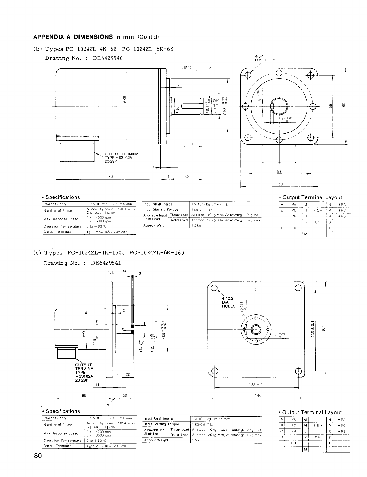
APPE:NDIX A DIMENSIONS in mm (Cent’d)
(b) ;~ypes PC-1024 ZL-4K-68, PC-1024 ZL-6K-68
I)rawing No. : DE6429540
,.
,.,5 Iiy
4-54
DIA HOLES
/
—
c Specifications
Allowable Input Thrust Load AI S!OP 10k9 ma. At rotat,.9
~“””%
Aoorox Weioht
;E
(c) Types PC-1024 ZL-4K-16O, PC-1024 ZL-6K-16O
Drawing No. : DE6429541
14
~.15+o
–0
1 1’1
2
Ill
Radial Load Al stop 20kg max, At ro[at,r,g
—
8
*
a
x
115ka
-+
k
4-10.2
DIA m
HOLES ~
—
56
● Output Terminal Layout
A
PA G N
B] Pc H“
1 1
c PB J R’ * PB
F
+5V 1P
M
* PA
* Pc
+
+
. .
r,
~+o.05
-0
$
“* Specifications
Pc,wer Supply
N~,mber of Pulses
M,,. ReSPO.Se Speed
Operat,on T.fnperature
Ot)tput Term, nals
80
OUTPUT
TERMINAL
TYPE
MS3102A
20-29P
+ 5 VOC A 5 % 350mA ma.
A- and 8.~hases
+
5“
● Output Terminal Layout
1C24 o/rev
Al PA IGI
—4
B PC H
, ,
+5V P * Pc
* PA
IN
I
Page 87

APPENDIX B 1/0 PORT ADDRESS SETTING
(1) 10 20
Short plug (SW1) setting and 1/0 module Nos.
are shown below.
Swl
16
1
2 -l 15
3
4
~
I
6
7
8
H
(3) ADDRESS CLASSIFICATION (COMPARISON
BETWEEN LX2 AND LX3)
Address classifications of IOOIB , 1002, SP20,
1020-01, 1020–02, and 1020-03 are as follows:
(a) Input Port
1001 B
Modu
No.
# 1000
to
1013
#
#1016
2 2
#
#
3
to
# 1045
# 1048
to
1061
#
---+ I No module selected I
--- I Module No 1 selected \
--+ \ Module N02 selected I
14
---+ I Module NO.3 selected I
13
Module No, 4 selected
} Spare
I
1002 SP20–02
Address
Port
# 1000
# ::07
# 1008
# It:l 5
#1016
# lt;23
# 1024
# ::31
# 1032
to
# 1039
# 1040
3
029
032
+
12
11
10
9
F
I
–––- I
---+11
1–1
1–2
2–1
2–2
3–1
3–2
Area
No.
1–1
1–2
2–1
2–2
3–1
3–2
I
Address
Port
1000
#
# 1008
# ;:15
#1016
# ?023
# 1024
# ::31
# 1032
# ;:39
# 1040
# ::47
(2) SP 20
Short plug (SW2) setting and 1/0 area Nos. are
s hewn below.
4
5
6
7
8
B
10 20–01 1020–02
Module
No.
Address
Port
# 1005
1
2
3
4
to
1009
#
#lo13
# 1021
# ;:25
# 1029
# 1037
# ;:41
# 1045
# 1053
# ::57
# 1061
f
-LX2—
13
12
11
10
9
~k
Modu
No.
I I
Area No. 1-2 selected
Area No. 2-1 selected
Area No. 2-2 selected
Area No. 3-1 selected
Area No. 3-2 selected
Address
Port
# 1000
1
#
:;09
# 1013
#1016
# i:25
# 1019
# 1032
3
4
LX3——
# ::41
# 1045
# 1048
to
# 1057
g 1061
Module
No.
1
2
3
4
1020–03
Address
Port
# 1000
to
#lo13
#1016
to
1029
#
# 1032
to
1045
#
# 1048
to
# 1061
I
Page 88
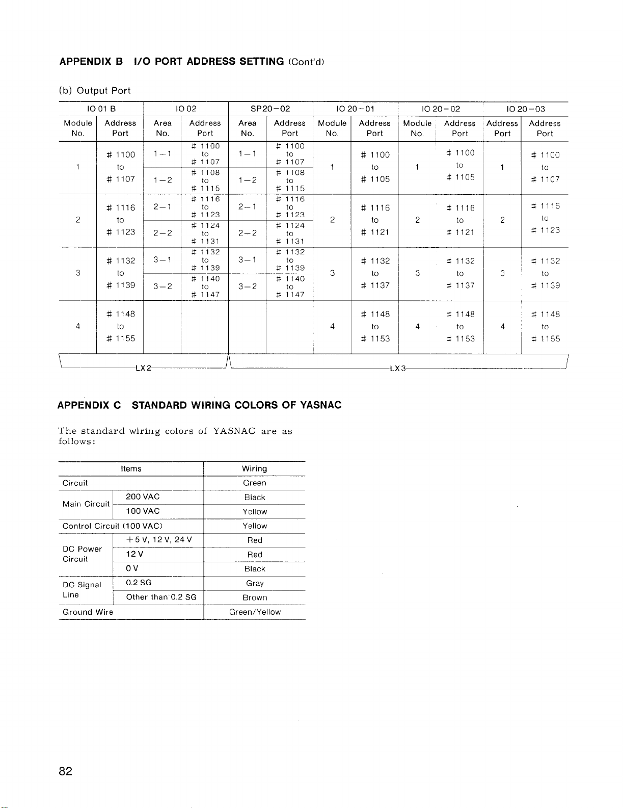
APPENDIX B 1/0 PORT ADDRESS SETTING (Cent’d)
(b) output Port
1001 B 1002
Module
N().
Address
Port
# 1100
1
2
3
to
1107
#
#1116
to
#1123
# 1132
to
# 1139
# 1148
to
#1155
-LX 2—–
Area
No.
1–1
1–2
2–1
2–2
3–1
3–2
Address
Port
#l loo
# ;;07
#1108
*;?15
#1116
# 1124
# ;:31
#1132
# 1140
_* ;:47
SP20–02
Area
No.
1–1
1–2
2–1
2–2
3–1
3–2
I
Address
#l loo ~
# ::07 ~ ,
# 1108
~Module
Port
I
1020–01
No.
2
3
4
Address
Port
# 1100
to
#llo5
.
#1116
to
#1121
#1132
to
#1137
#1148
to
#1153
—LX3
10 20–02
Module Address
No. ~ Port
41100
1
2
3 to
4
to
$1105
X1116
to
$1121
41132
41137
~ 1148
to
41153
10 20–03
Address
Port
1
2
3
4
Address
Port
#lloo
#llo7
#1116
41123
41132
$1139
$1148
I
#1155
.—.1
to
to
to
to
APPI:NDIX C STANDARD WIRING COLORS OF YASNAC
The standard wiring colors of YASNAC are as
follows :
Items Wiring
Circuit
Mairl Circuit
Conirol Circuit (100 VAC)
DC Power
Circuit
DC Signal
200 VAC
100 VAC
I
+5 V>12V,24V I
I
12V
Ov
I
I
Green
Black
Yellow
Yellow
Red
Red
Black
‘ine H ::.–
Gro~}nd Wire
I
Green/Yellow
82
Page 89

83
Page 90

YASNAC LX3
CNC SYSTEM FOR TURNING APPLICATIONS
CONNECTING MANUAL
TOKYO OFFICE Ohtemachl Bldg 1-6.1 Oh!emach[ Ch[yoaa-ku, Tokyo, 100 Japan
Phone (03)3284-9111 Telex YASKAWAJ33530 Fax (03)3284-9034
SEOUL OFFICE 8th Floor Seoul Center Bldg, 91.1, Sogong-Dong Chung-ku, Seoul, Korea 100070
Phone (02)776-7844 Fax(02) 753.2639
TAIPEI OFFICE Shen Hs!ang Tang Sung Ch]ang Buldlng 10F 146 Sung Chlang Roac Talpe[ Taw,an
Phone (02)563-0010,.7732 Fax (02)567.4677
YASKAWA ELECTRIC AMERICA, INC.
Chicago-Technical Center
3160 }MacArthur Blvd Northbrook, IL 60062-1917, USA
Phone (708)291-0411 Fax (708)291-1018
Los Angeles Ofhce
5626 Corporate Avenue Cypress, CA 90630 USA
Phone (714)828.9692 Fax (714)828.1165
New Jersey Office Riverdale One, 44 Route23 North, Suite 5 Rlverdale NJ 07457.1619 US).
Phone (201)835-9512 Fax(201)835-95tl
YASKAWA ELECTRIC EUROPE GmbH
Monschauer Strasse 1, 40549 Dusseldorf 11, Germany
Phone (0211)950030 Telex (41) 8588673 YASD D Fax (0211)507737
YASKAWA ELECTRIC (SINGAPORE) PTE. LTD.
Head Ofhce CPFBldg, 79 Robinson Road # 13-05, SngaporeO 106, SINGAPORE
Phone 2217.530 Telex (87)24890 YASKAWA RS Fax 224.5854
SeNice Center 221 Henderson Road, # 0720 Henderson BulldngS lngapore0315, SINGAPORE
Phone 276-7407 Fax 276-7406
YATEC ENGINEERING CORPORATION
Shen Hslang Tang Sung Chlang Building 10F 146 Sung Ch}ang Road, Tatpel, Talv/an
Phone (02)563-0010 Fax(02)567-4677
YASKAWA ELECTRIC CORPORATION
Y
YASKAWA
Due to -,w paixt md)ficat,ort/,mwovmen<data s“b,et to ct!a”ge w,M not,..
.
TO E-C843-9.22B
@
Printed in Japan October 199386.6 0 6WA ~
 Loading...