

Page 1
YASNAC LX3
CNC SYSTEM FOR TURNING APPLICATIONS
MAINTENANCE
Before initial OF
)eration read these instructions thoroughly, and retain for future reference
YASUAVVA
Page 2
This manual is primarily intended to give operator’s maintenance instruc-
tions for YASK!”ICLX3.
The information contained in manual does not provide all details to be
met. concerning maintenance and troubleshooting.
If uncertainties be
encountered for particular maintenance operation, refer to the following
YASNACLX3documents for additional information:
. YASNACLX3/llX3PC SYSTEM(TOE-C843-9.1)
. YASNACLX3SPECIFICATIONS(sIE-C843-9.20)
. YASNACLX3OPERATOR’S MANUAL(TOEC843-9. 20)
. YASNACLX3CONNECTINGMANUAL(TOE-C843-9. 22)
a ---- .
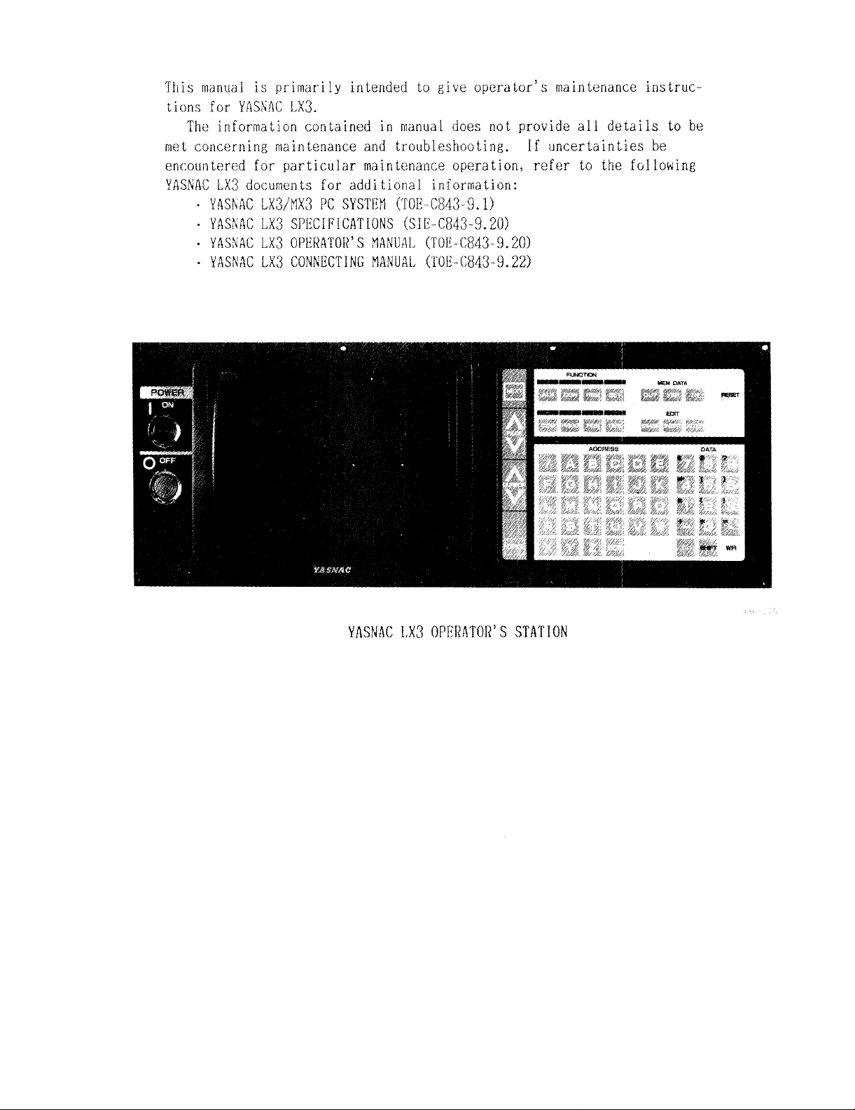
YASNAC1,X3OPllRfiTOR’SSTATION
Page 3
TABLEOF CONTENTS
1. OUTLINE1
1.1 COMPONENTARRANGEMENT1
1.2 CONSTRUCTION3
1.3 MAJORCOMPONENTS5
2. ROUTINEINSPECTIONSCHEDULE7
2.1 TAPEREADER8
2.2 CONTROLPANEL 8
2.3 ACSERVOMOTOR8
2.4 BATTERY9
3. MAINTENANCEINSTRUMENTS10
4. TROUBLESIIOOTING11
4.1 TROUBLEIDENTIFICATION11
4.2 TROUBLESBOOTINGBYALARMCODES 12
7. SETTINGANDADJUSTMENTFORMODULE56
7.1 MB20BOARD56
7.2 SP20 BOARD57
7.31020 BOARD57
7.4 1021 57
7.5 AREANOSETTINGAND1/0 ADDRESSPORT 5!3
8. NCDATABANDLING60
8.1 SYSTEMNO. SETTING(#6219) 60
8.2 DISPLAYINGANDWRITINGPARAMETERS60
8.3 DISPLAYINGANDWRITINGKEEPMEMORY62
8.4 TAPEINPUTOF SETTINGDATAANDPARAMETER
DATA62
8.5 PUNCBING-OUTOF SETTINGDATAAND
PARAMETERDATA63
4.3 TROUBLESHOOTINGWIT11OUTALARMCODES 28
4.4 MAINTENANCEOF ACGC 45
4.5 SUPPLYVOLTAGECIIECK 47
4.6 INPUT/OUTPUTSTATUSDISPLAYBYON-LINE
DIAGNOSTICSFUNCTION(DGN) 48
5. ADJUSTMENTSUPONINSTALLATION50
5.1 ADJUSTKIH{TPROCEiNRES50
6. MODULE/UNITREPLACEMENTPROCEDURE53
6.1 CPUUNIT 53
6.2 OPERATOR’S PANEL 54
6.3 OPTIONALMODULES55
8.6 SUMMARYOF STORINGDATAANDEDITING
OPERATIONS64
APPENDIX1 LIST OF ALARMCODE 65
APPENDIX2 LIST OF DATA 96
APPENDIX3 LIST OF SETTINGNOMBERS104
APPENDIX4 LIST OF PARAMETERNUMBERS112
APPENDIX5 STOREDLEADSCREWERROR
COMPENSATION130
APPENDIX6 LIST OF STANDAKDINPUT/
OUTPUTSIGNALS 131
Page 4
INDIX
SUBJECT CHAPTER SECTION
AACSERVOMOTOR ”” S”.+.”*’ “.0” .”000””2. ”2.30 .8
ACGCALARMINDICATION*O” O* OOO*
ADJUSTMENTPROCIIDURES”+””. ”0
ADJUSTMENTSUPONINSTALLATION* “ “ “ . . “ o 0 0 “ + o 5 “ s 5.
ALARMO1OANDO1I (Parity Error)
● “ “ ● ‘ “ ● s “ ● “ “ 4 “ “ 4.2.1 “ “ 12
●o*{oco *4*04.4.20*45
●*””O”OO” 05..5.1” “50
● “ 50
ALARM075, 076, 077 (RS232C Faulty) “ . . “ “ “ . 0 “ “ 4 “ . 4.2.2 s “ 14
ALARM170, 172, 173, 174 AND175 (MemoryError) . “
ALARM179 (Temperature Alarm inside the Panel)
● “ “ ● “ 4 “ “ 4.2.4 ● “ 18
ALARM31O(Servo Power Supply Incomplete) “ . . “ “
ALARM320 (Control Not Ready)
ALARM323(ACGC2SYNC ERROR)”*”” O”
ALARM325 (Servo CPUError) .
● “ ● “ “ ● “ “ “ o “ . “ 4 “ ● 4.2.9 s “ 21
● *”. oQ”” 4.” 4.2.18 ““ 27
● ● ● ● ● ● “ . . c o “ ● 4 . “ 4.2.15 ● “ 26
ALARM329 (Built-in type PC CPUError)” + “ o “ “ “ .
ALARM330 (Emergency Stop)” “
ALARM820 (ROM/RAMCheckError) “ .
● ● “ ● . + o “ “ “ . * ● 4 ‘ “ 4.2.10 “ “ 22
● ● “ ● ● ● “ ● ● “ 4 ● o 4.2.17 ● ● 26
ALARMS231 AND232 (Zero Point Return Area Error)
● ‘ 4 . “ 4.2.3 “ . 17
● “ 4 . 0 4.2.8 ● o 21
● 4 “ o 4.2.16 . 0 26
● “ ● 4 “ “ 4.2.5 ● o 19
ALARMS241 AND242 (Reference Point Return Area Error) “ 4 “ “ 4.2.6 “ “ 20
ALARMS271 AND272 (P-SET Error)* “ “ “
ALARMS331 AND332 (Servo Fuse Blown) . .
ALARMS341 AND342 (Servo Error)
● . ● ● ● ● ● ● “ ● ● ● 4 “ ● 4.2.12 ● ● 23
● “ o “ “ ‘ “ ● 4 “ . 4.2.7 “ + 20
● ● “ ● . + ‘ 4 “ . 4.2.11 ● “ 22
PAGE
ALARMS351 AND352 (Motor Overload) “ + “ “ “ “ “
ALARMS361, 362 AND366 (PG Disconnection Error) . . “ . 4 s
● “ “ 4 ● “ 4.2.13 0 . 24
● 4.2.14 . “ 25
APPENDIXILISTOF ALARMCODE”* “*0””00”0*””.”*”0 ““””” 65
APPENDIX2LISTOFDATA” *”’” ““”””’””’”””””””” “’”””915
APPENDIx3LIsToF sETTrNGNuMBERs ““””’””’”’””””””” ““””104
APPENDIX4 LIST OF PARAMETERNUMBERS“
APPENDIX5 STOREDLEADSCREWERRORCOMPENSATION“
APPENDIX6 LIST OF STANDARDINPUT/OUTPUTSIGNALS + +
● . 0 “ . + “ “ ● “ “ o “ + o “ . ● + 112
● “ ‘ o “ “ . ● ● “ o . . . 130
● . “ ● . 0 c o “ “ “ “ lQl
AREANOSETTINGAND1/0 ADDRESSPORT” “ “ . . “ . + “ “ 7 “ o 7.5
BBATTERY”*.so”””.””.” “..””””.o”+2.”2,4
C CHECKACPOWERSUPPLYVOLTAGEo
● “ ● “ . ● + . “ ● ● ● 4 0 “ 4.5.1
CHECKDCPOWERSUPPLYVOLTAGE.“. . “ s “ “ “ “ . . “ “ 4 “ - 4.5.3
COMPON!3NTARRANGEMENT””O” “+”.””0.”*””” 1“” 1.1
CONSTRUCTIONO. “ “ “ “ “ “ “ “. + “ “ “ o 0 “ “ “ “ “ 1 “ “ 1.2
CONTROLPANEL “
● ● “ “ ‘**” ““ . 0 .* o “ “ ● “ ● 2 “ “ 2.2
II
. .
. .
. .
. .
. .
. .
. .
101
59
9
47
48
1
3
8
Page 5
INI)IX
SUBJIK1’
c
DISPLAYINGANDWRITINGKEEPMEMORY
D
● ● “ “ “ ● ● “ “ ● ● 8 “ o
DISPLAYINGANDWRITINGPARAMETERSs “ o ● “ ● o + “ “ ● 8 “ o
E
EDIT DOESNOTFUNCTION”QO*”O O“”OO””OS”O 4+”
FAULTSNOTDISPLAYEDACGCALARMINDICATION”
F
● o ● ● ● “ 4 “ +
H
INDICATIONLAMPOF POWERSUPPLYUNIT” “
I
● “ ● “ o 0 0 “ 4 0 0
INITIAL DIAGNOSTICERRORDISPLAYATI’OWERAPPLICATION“ 4
INPUT/OUTPUTSTATUSDISPLAYBYON-LINEDIAGNOSTICS
FUNCTION(DGN)O****OO*” *O””
●00*0 ”” *4”*
1020 BOARD””””””””””””””” ““””””””7””
10210.”000.o”””ooc”**. 0“”0”0”*7+0
CHAPTER
SECTION
4.3.3
6.1
4.3.4
4.3.9
8.3
8.2
4.3.13
4.4.3
4.3.5
4.5.2
4.3.2
4.6
7.3
7.4
. .
. .
. .
. .
. .
. .
. .
. .
. .
. .
. .
. .
. .
PAGE
29
53
30
35
62
60
40
45
30
48
29
48
57
57
MAINTENANCEINSTRUMENTS
M
● ● ● “ ● + s ● ● ● o “ ● ● ● ● 3 + ●
tlAINTENANCEOF ACGC*””” 00 O+” ● *””” 0.0”40s
MAJORCOMPONENTS””” O” DO Q”~OQ ““O OO” C”l SO
MANUALJOG MODEOPERATIONFAULTY*+ “ +
● “ ● ● ● ● ● “ 4 Q ●
MANUALRAPIDMODEOPERATIONFAULTY“ ● ● ● ● ● “ ● “ o “ 4 “ ●
MANUALZERORETURNOPERATIONFAULTY● “ o + “ “ ● ● ● ● 4 “ “
MB20BOARD””””””””””””””” ““””””””7””
MODULE/UNITREPLACEMENTPROCEDURE
● ● + ● c ● ● “ “ “ c 6 “ ●
NCDATAIIANDLING*”” BOO.”**** “*”00”0”80*
9* CRTSCREENIS DARK””””””””” ““””””””4””
OPERATINGPROCEDURETO DISPLAYINPUT/OUTPUTSIGNALS
o
● ● 4 ● ●
OPERATIONIS NOTAVAILABLEWITHGO1, G02 ORG03 “ ● o ● 4 0 ●
OPERATIONIS NOTAVAILABLEWITHG32, G76 ORG92 “ “ ● ● 4 . c
OPERATOR’SPANELO
OPTIONALMODULES*
● + . “ “ ““ “ o ● OO ● “ “ ● o ● “ 6 “ “
● ● ● “ “ ● + ● ● ● + ● ● ‘ ● s ● ● ● 6 “ o
3.
4.4
1.3
4.3.6
4.3.7
4.3.8
7.1
6.
8.
4.3.12
4.6.2
4.3.10
4.3.15
6.2
6.3
1.
4.6.1
. .
. .
. .
. .
. .
. .
. .
. .
. .
. .
. .
. .
. .
. .
. .
. .
. .
10
45
5
32
33
34
56
53
60
39
49
36
42
54
55
1
48
RI
Page 6
INDIX
SUBJECT
CHAPTER SECTION
PAGE
P PARAtlETERDATADISPLAY”””*” ““.”’”~””0”” 8“” 8.2.2 ““ 61
PA[{AHETERTYPES ”O” OO”. ”O ””* ““”” ”””’ 8”08.2.1*”61
POWERC8NNOTBESUPPLIED”O”. .O”” .“”””.”. 4.* 4,3.1 “O 28
PUNCHING-OUTOF SETTINGDATAANDPARAMETERDATB “ “ “ ‘ 8 “ Q 8.5 e
o 63
R RUCOGNI’rIONOF NCSYSTEM”.O.” “’””+””””~” 4“. 4.1.2 .. 11
RECOGNITIONOF TROUBLESTATUS “ . 0 . “ s . s “ o “ “ . 4 “ “ 4.1.1 “ “ 11
ROUTINEINSPECTIONSCHEDULEo . “ “ “ “ “ “ “ “ “ “ . 0 2 0 s 2. “ “ 7
Rs232C DOESNOTFUNCTIONWELL“ “ “ . “ “ “ “ “ “ “ . “ 4 “ “ 4.3.14 0 “ 41
S SETTINGANDADJUSTMINTFORMODULE.
● . “ “ “ “ “ . “ “ 7 . s 7. 0 “ 56
SKIP FUNCTION(G31) OPERATIONFAILURE o . “ . 0 “ “ . “ 4 “ “ 4.3.16 . “ 43
SOFTWAREVERSIONINDICATION. “
● . 0 0 “ “ o “ o “ “ “ 4 0 s 4.4.4 0 “ 46
SP20BOARD””O. .OS”” O”” *-O ““”” ”0”07”.7.2””57
SPINDLEDOESNOTROTATE”””. “.”””..””””” 4.” 4.3.11 .“ 37
SUMMARYOF STORINGDATAANDEDITINGOPERATIONSo
● “ “ . 8 “ “ 8.6 “ . 64
SUPPLYVOLTAGECliECK” **”””” “..00””””*~4””4.5 ‘.47
SYSTEMNO. SETTING(#6219) ”OO” O”0 ““O”OOCS 8.” 8.1 .“ 60
T TAPEINPUTOF SETTINGDATAANDPARAMETERDATA “ “ “ ~ Q 8 “ “ 8.4 “ “ 62
TAPEMODEDOESNOTFUNCTION00 ””” +. ”.”””.” 40~ 4.3.17 “* 44
TAPEREADERo
● “ . 0 + . “ o “ “ ● ● “ “ Q “ o 0 “ . “ 2 . “ 2.1 ““ 8
TROUBLEIDENTIFICATION”””” .0”00 ““00.+”” 4“” 4.1 “O 11
TROUIILESliOOTING*”. .O”””” O*O 0“.”0”.*40.4.””
TROUBLESHOOTINGBYALARMCODES“ . .
TROUBLESHOOTINGSERVICEOF ACGC
0 . “ . * . “ “ o “ 4 “ . 4.2 “ “ 12
● “ “ “ + . “ “ - “ “ ● 4 0 ● 4.4.1 “ o 45
TROUBLESHOOTINGWITHOUTALARMCODES o “ “ “ “ s “ . “ “ 4 “ “ 4.3 “ “ 28
W WI{ITINGPARAMETERDATA””’”” .-”.””’’”... 8“. 8.2.3 “- Cl
N
Page 7
1. OUTLINE
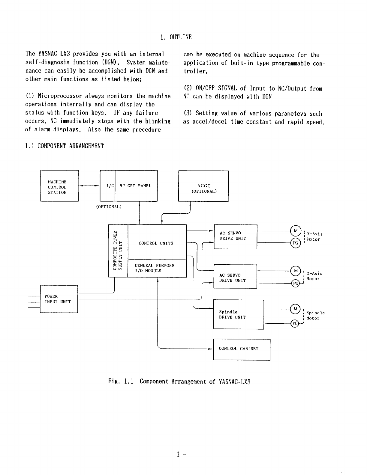
The YASNACLX3provides you with an internal
self-diagnosis function (DGN). System maintenance can easily be accomplished with DGNand
other main functions as listed below;
(1) Microprocessor always monitors the machine
operations internally and can display the
status with function keys. IF any failure
occurs, NCimmediately stops with the blinking
of alarm displays. Also the same precedure
1.1 COMPONENTARRANGEMENT
MACNINE
CONTROL
STATION
1/()
9’sCRT PANEL
D’
(OpTIONAL)
v
d
2
EEJ
Ia.lz
w=
H
~g
Ucn
I
CONTROL UNITS
GENERAL PURPOSE
1/0 MODULE
be executed on machine sequence for the
can
ication of buit-in type programmable con-
apo
ler,
tro
ON/OFFSIGNALof Input to NC/Output from
(2)
NCcan be displayed with DGN
(3) Setting value of various
as accel/decel time constant
parameters such
and rapid speed.
ACCC
(OPTIONAL)
)
.
AC SERVO
DRIVE UNIT
f---
7
---
[
AC SERVO
DRIVE UNIT
—
1
X-Axis
kbtor
I
+ CONTROL CABINET I
Fig. 1.1 Component Arrangement of YASNAC-LX3
–l–
Page 8
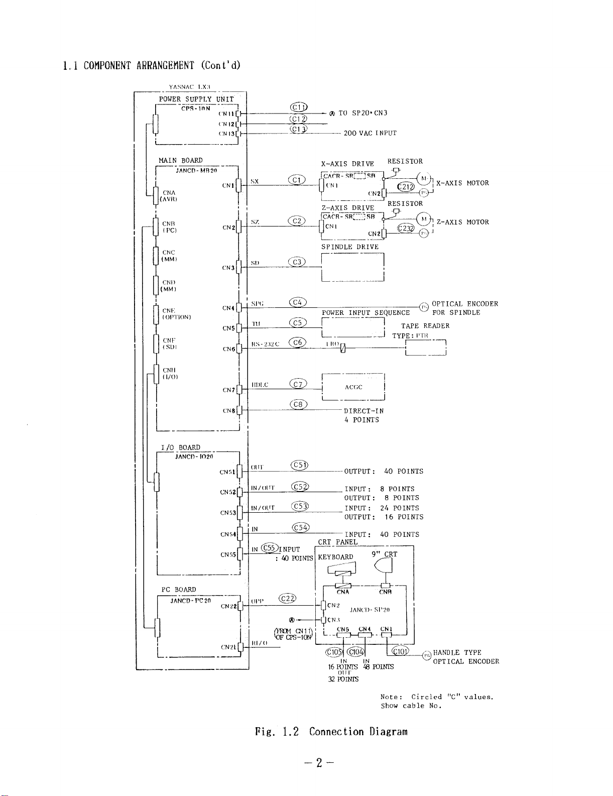
1~1 COMPONENTARRANGEMENT(Cont’ d)
YASNA(’ 1.X:1
—.
POWER SUPPLY UNIT
~-cPs.,”t4 --1
u
-.
NAIN BOARD
~-;ANCt3- kmzo -
CNA
(AVN)
0
,
CNI{
PC)
(
.
f-
CNC
(MM)
u
CNI)
(MM)
(1
1
CNI;
( OP”I”ION” )
CNl(Sl))
(’Nil
(’N12
(’N13
-J
CNl
1+
CN z
CN 4
CN5
(’N 6
1
cNII
( 1/[))
/.., *
G,. ,
!
i
L
c’N 8
-~ ,
<
+
5X
,1
ST
&
1
S1’(i
‘Ill
NS-2.i2C
111)1.c
r+I
!--L
!1
@
‘cl
@l
cl
C2
~
~
C6
\c7J j
@j
m TO
SP20. CN3
200 VAC INPUT
X-AXIS DRIVE
Fr;w$x-mlsMOTOR
~;%%y’- Z-A’IS MOTOR
k’--,-’
SPINDLE DRIVE
poWER INPUT SEQu_OpTIcM ENCODER
~.—
L-. _~
1
lto~
AC(; C
RESISTOR
FOR SPINDLE
“1
TAPE READER
TYP; :III’1{ ~
1
L _ti
]
L-_. -J
DIRECT-IN
4 POINTS
I/0 _BOARD
JANCD - 1020-
[
—-
cN51
CN52
cN53
CN54
0111”
m
OUTPUT : 40 POINTS
INPUT :
OUTPUT : 8 POINTS
INPUT : 24 POINTS
OUTPUT :
CRT PANEL
32 Fonm
8 POINTS
16 POINTS
40 POINTS
Note :
Show cable No.
Fig. 1.2 Connection Diagram
OPTICAL ENCODER
Circled “C” values.
–2–
Page 9
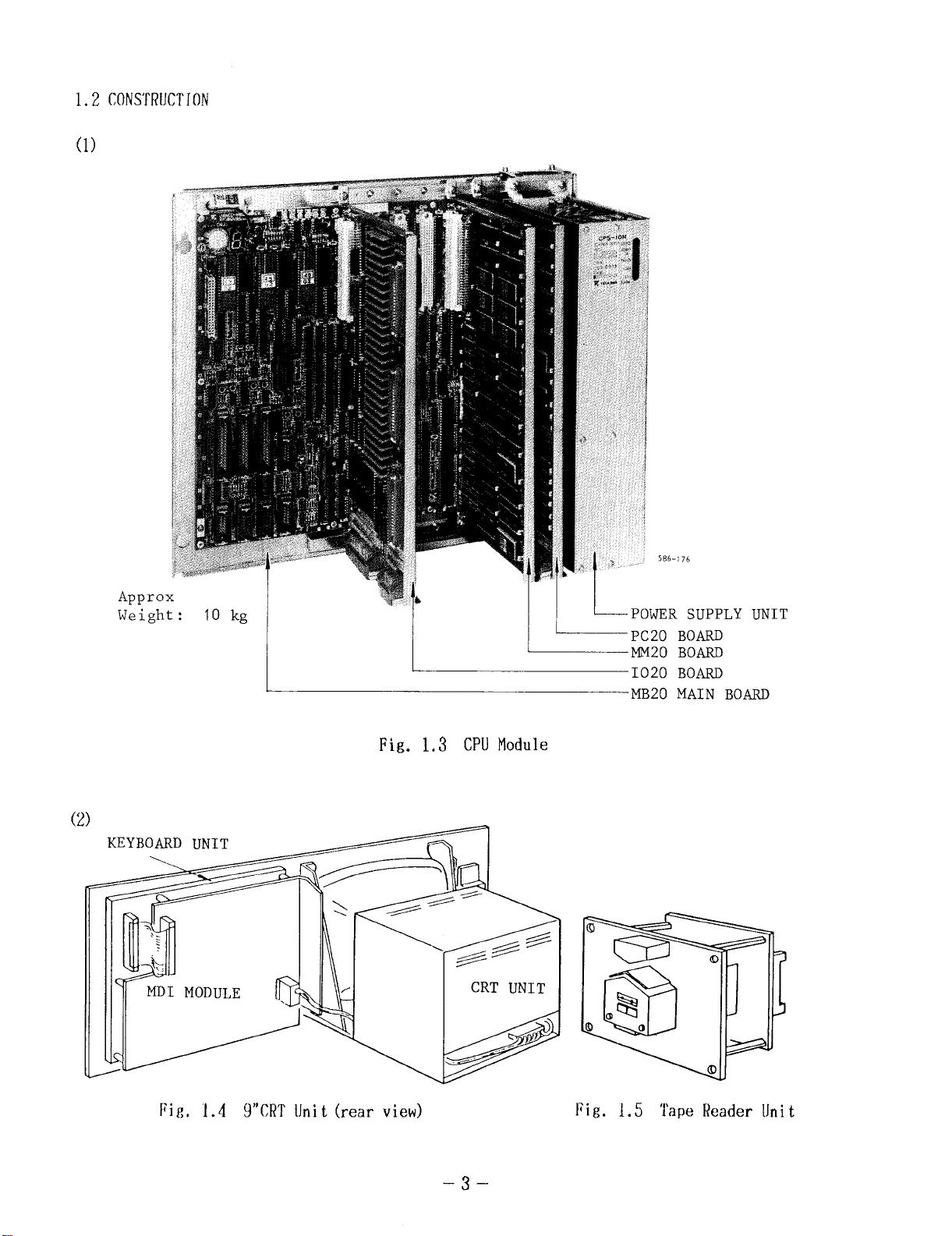
1.2 CONSTRUCTION
(1)
(’2)
Appr(
Weigl
-176
SUPPLY
L
BOARD
BOARD
I
BOARD
MB20 MAIN BOARD
UNIT
Fig. 1.3 CPUModule
Fig. 1.4 9“CRT Unit (rear view)
Fig. 1.5 Tape Reader Unit
–3–
Page 10
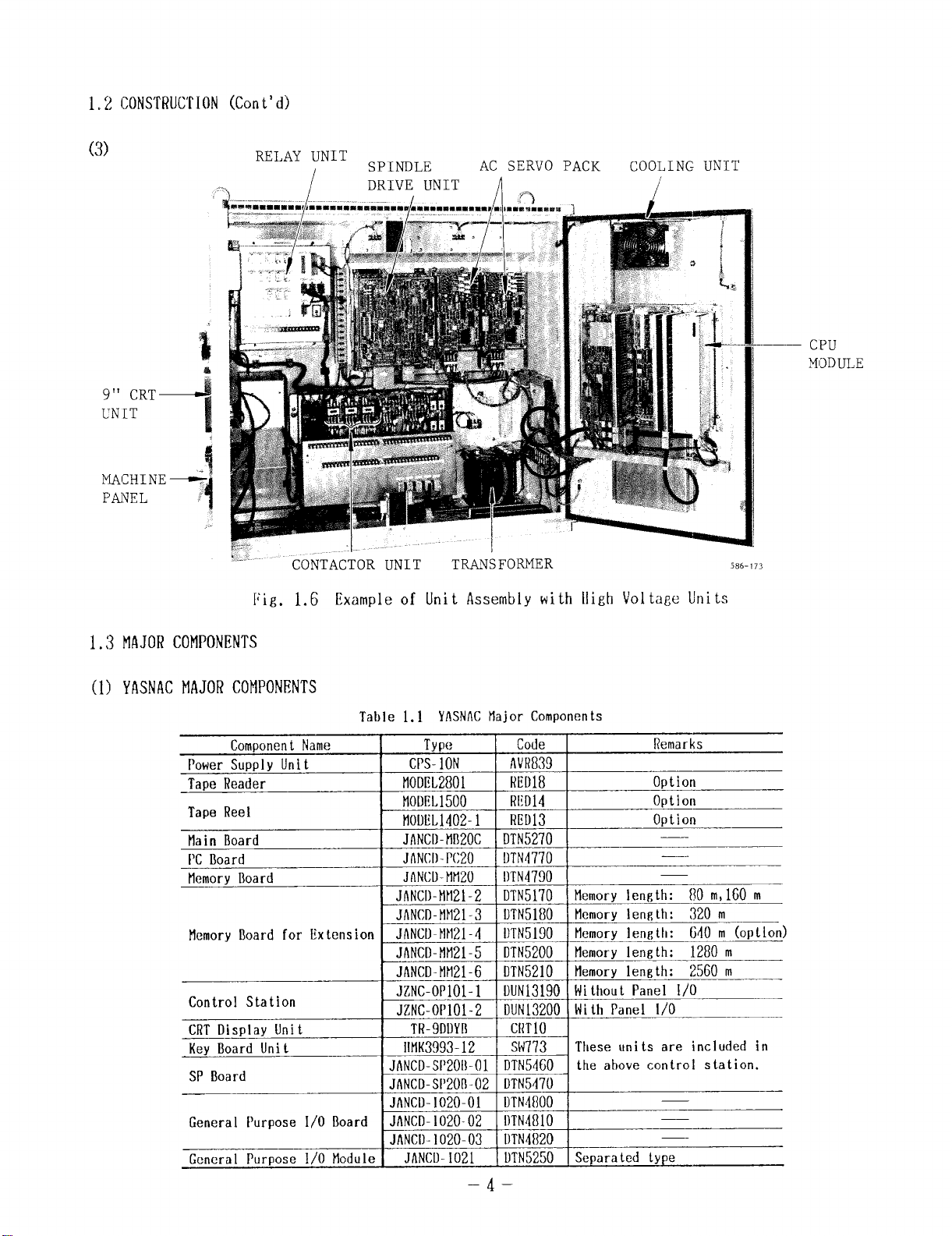
1, z CONSTRUL’TION(Cont’ d)
(3)
RELAY UNIT
:.-
J
/
CONTACTOR UNIT
SPINDLE
DRIVE UNIT
Fig. 1.6 Example of Un
AC SERVO PACK
J ..> /
TRANSFORMER
COOLING UNIT
t Assembly with High Voltage Units
— CPU
M,~I)lJLE
586-173
MAJORCOMPONENTS
1.3
YASNACMAJORCOMPONENTS
(1)
ComponentName
PowerSupply Unit
TapeReader
Tape Reel
tfain Board
PCBoard
tlemoryBoard
MemoryUoardfor Extension
Control Station
CRTDisplay Unit
KeyLtoardUnit
SP Board
General Purpose 1/0 Board
General Purpose 1/0 Module
Tahte 1.1 YASNACHajor Components
Type
CPS-1ON I I
MODEL2801
t10DflL1500
t10tIEL1402-1
Code
AVRKN
RED18
RLD14
RED13
I
Remarks
Option
OptIon
Option
JANCI)-MB20CDTN5270
JANCI)-PC20
JANCD-MM20
DTN4770
OTN4790
JANCI)-MM21-2DTN5170 Memorylength: [?0m,160m
JANCD-MM21-3DTN5180 Memorylength: 320 m
JANCI.-NN21-4
DTN5190 Memorylength: 640 m (option)
JANCD-MM21-5DTN5200 Memoryleneth: 1280m
JANCD-tlH21-6DTN521OMemorylength: 2560m
JZNC-OP1O1-1DUN13190Without Panel 1/0
JZNC-OP1O1-2DUN13200\With Panel 1/0
TR-9D+T,0 ,
These units are included in
the ahove control station.
JANCD-102O-OI
DTN4800
JANCD-1020-02 DTN481O
JANCO-102O-O3OTN4820
JANCD-1021
DTN5250
Separated type
–4–
Page 11
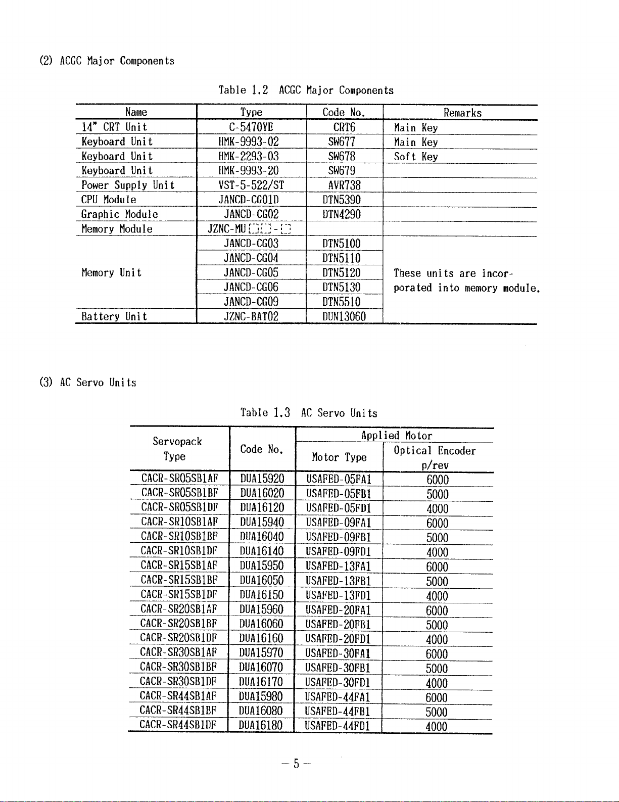
(2) ACGCMajor Components
Table 1.2 ACGCMajor Components
14” CRTUnit
Keyboard Unit
Keyboard Unit BMK-2293-03
Keyboard Unit
Power Supply Unit
CPUModule
Graphic Module
MemoryModule
MemoryUnit
Battery Unit
(3) ACServo Units
Name Type
C-5470YE CRT6 Main Key
HMK-9993-02
HMK-9993-20
VST-5-522/ST AVR738
JANCD-CGOID
JANCD-CG02
JzNc-Mu::;::: - ~:;
JANCD-CG03 DTN51OO
JANCD-CG04
JANCD-CG05 DTN5120 These units are incorJANCD-CG06 DTN5130
JANCD-CG09
JZNC-BAT02 DUN13060
Code No.
SW677
Main Key
SW678 Soft Key
SW679
DTN5390
DTN4290
DTN511O
porated into memory module.
DTN551O
Remarks
Servopack
Type
CACR-SR05SB1AF
CACR-SR05SB1BF
CACR-SR05SB1DP
CACR-SR1OSB1AF
CACR-SRICISBIBF
CACR-SR1OSB1DF
CACR-SR15SB1AF
CACR-SR15SB1BF
CACR-SR15SBIDF
CACR-SR20SB1AF
CACR-SR20SB1BF
CACR-SR20SB1DF
CACR-SR30SB1AF
CACR-SR30SB1BF
CACR-SR30SB1DF
CACR-SR44SB1AF
CACR-SR44SB1BF
CACR-SR44SB1DF
Table 1.3 ACServo Units
Applied Motor
Code No.
DUA15920
DUA16020
DUA16120
DUA15940
DUA16040
DUA16140
DUA15950
Motor Type
USAFED-05FA1
USAFED-05FB1
USAPED-05FDI
usAiED-09FAl
USAFED-09FBI
USAFED-09FD1
USAFED-13FA1
DUA16050 USAFED-13FB1
DUA16150
DUA15960
DUA16060
DUA16160
DUA15970
DUA16070
DUA16170
DUA15980
DUA16080
DUA16180
USAFED-13FD1
USAFED-20FA1
USAFED-20FB1
USAFED-20FD1
USAFED-30FA1
USAFED-30FB1
_USAFED-30FD1
USAFED-44FA1
USAFED-44FB1
USAFED-44FD1
Optical Encoder
p/rev
6000
5000
4000
6000
5000
4000
6000
_
5000
4000
6000
5000
4000
6000
_
5000
4000
6000
5000
4000
–5–
Page 12
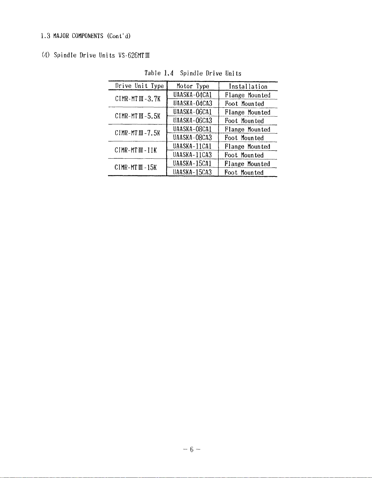
1.3 MAJORCOMPONENTS(Cont‘ d)
(4) Spi nd
e Drive Units VS-626FITIR
Table 1.4 Spinal e Drive Units
Drive Unit Type Motor Type Installation
cIMR-MTm-3.7K
CIMR-MTIII-5.5K
cIMR-MTnI-7.5K
CIMR-MTIR-llK
CIMR-MTUI-15K
UAASKA-04CA1 Flange Mounted
UAASKA-04CA3 Foot Mounted
UAASKA-06CA1 Flange Mounted
UAASKA-06CA3
UAASKA-08CA1
UAASKA-08CA3 Foot Mounted
UAASKA-llCA1 Flange Mounted
UAASKA-11CA3 Foot Mounted
UAASKA-15CA1 Flange Mounted
UAASKA-15CA3 Foot Mounted
Foot Mounted
Flange Mounted
-6-
Page 13
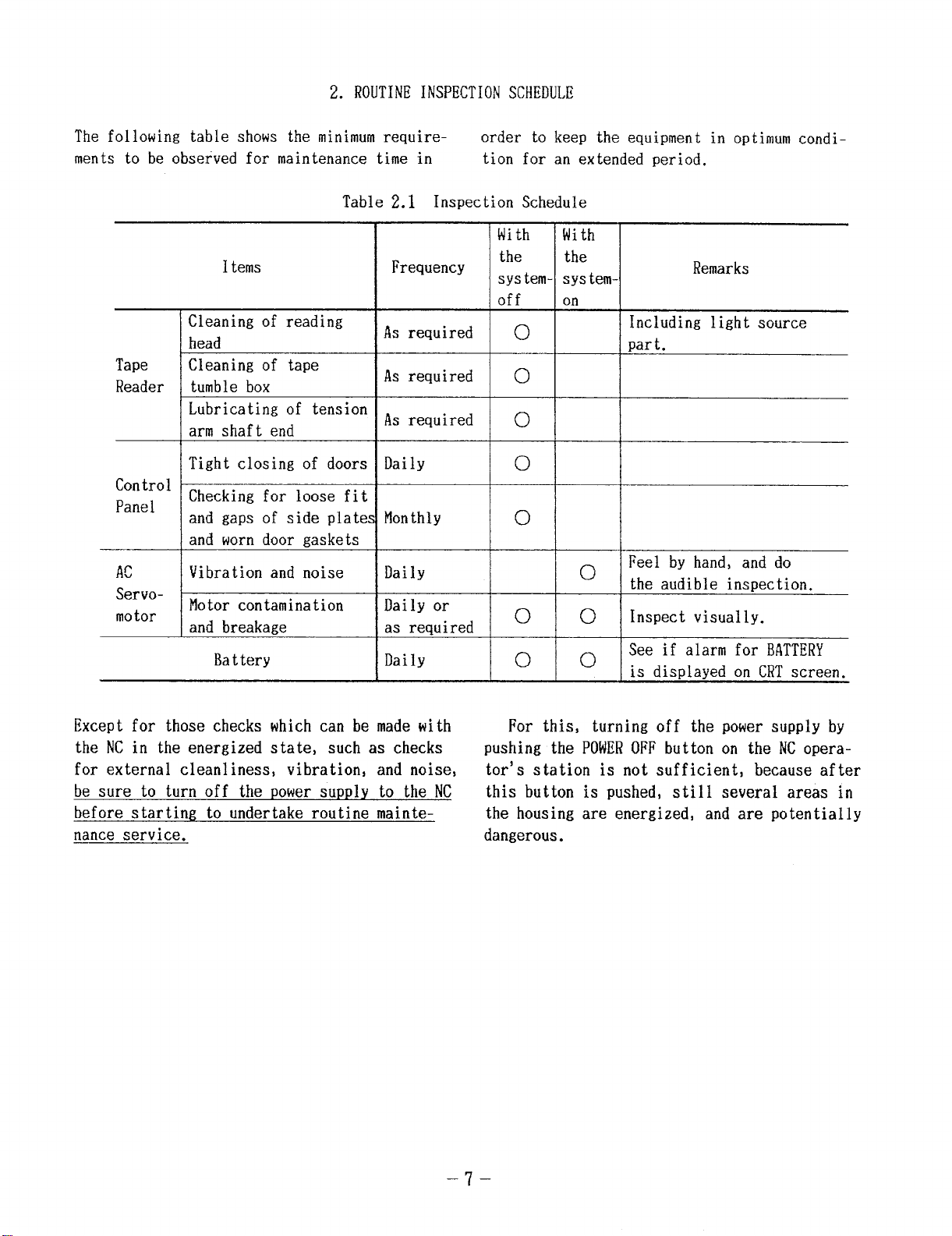
2. ROUTINEINSPECTIONSCHEDULE
The following table shows the minimumrequirements to be observed for maintenance time in
Table 2.1 Inspection Schedule
I terns
Cleaning of reading
head
Tape Cleaning of tape
Reader tumble box
Lubricating of tension
arm shaft end
Tight closing of doors Daily
Control
Panel
AC
Servo-
motor
Checking for loose fit
and gaps of side plates
and worn door gaskets
Vibration and noise
Motor contamination
and breakage
Battery
Frequency
As required o
As required o
As required o
MonthlY
Daily
Daily or
as required
Daily
order to keep the equipment in optimum condi-
tion for an extended period.
With
the
system- systemOff on
o
o
o 0
o 0
With
the
o
Remarks
Including light source
part.
Feel by hand, and do
the audible inspection.
Inspect visually.
See if alarm for BATTERY
is displayed on CRTscreen.
Except for those checks which can be made with
the NCin the energized state, such as checks
for external cleanliness, vibration, and noise, tor’s station is not sufficient, because after
be sure to turn off the power supply to the NC
before starting to undertake routine mainte-
nance service.
For this, turning off the power supply by
pushing the POWEROFF button on the NCopera-
this button is pushed, still several areas in
the housing are energized, and are potentially
dangerous.
–7–
Page 14
2.1. ‘TAPEREADER
(1) [Cleaning the tape reader head (Dai
(a) Removetape rubbish and dust from the
glass with a blower brush. If the glass is
stained with oil or oily dust, wipe it using
agauze or soft cloth with absolute alcohol.
Also clean the tape guide and the tape
retainer.
(b) Remove the dust, if any, on LED (light
source) on top with a blower brush.
(2) Cleaning of tape tumble box (Weekly)
Clean the braided nylon leading tape with a
clean, soft cloth.
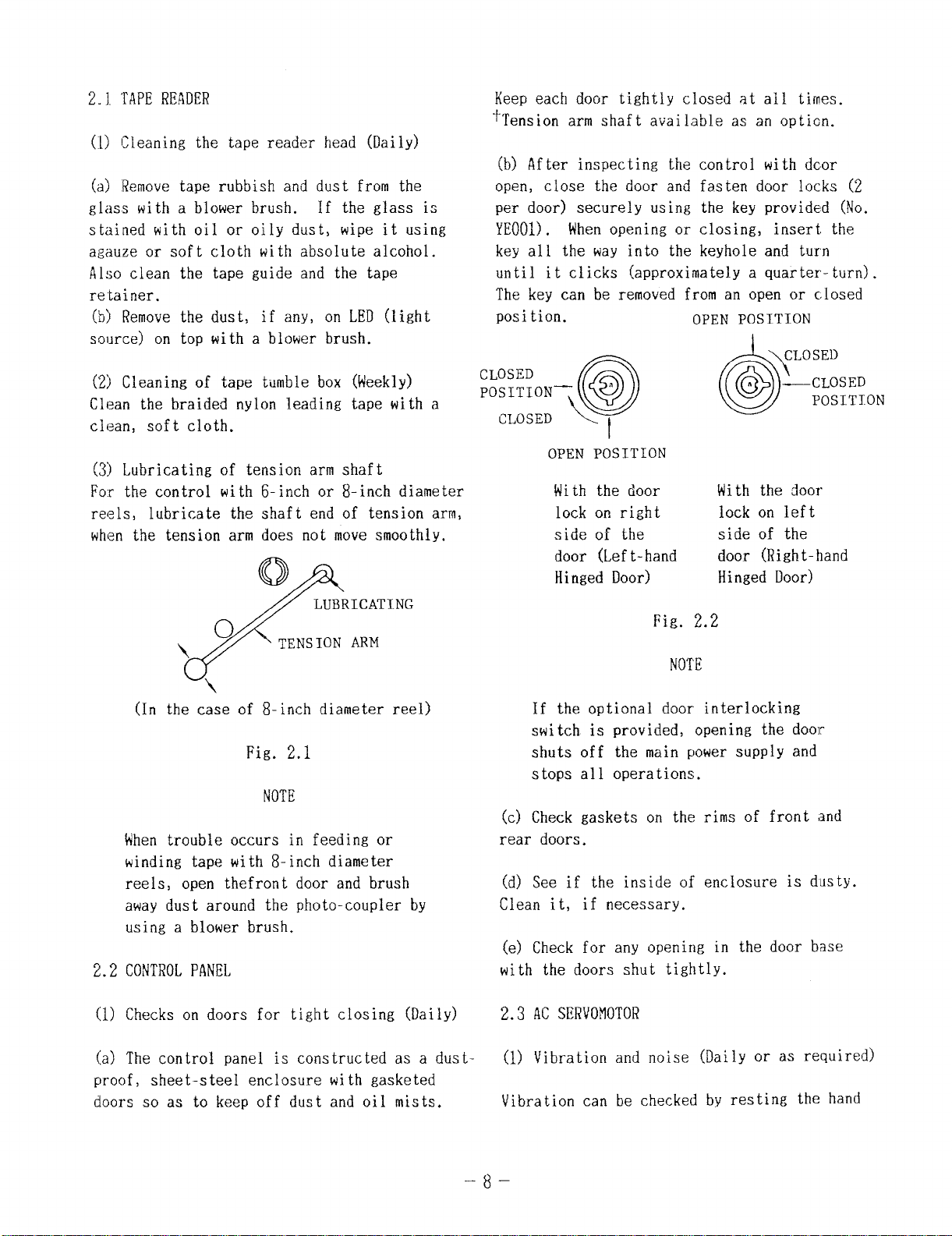
(3) Lubricating of tension arm shaft
Fo:r the control with 6-inch or 8-inch diameter
reels, lubricate the shaft end of tension arm,
when the tension arm does not move smoothly.
lY)
Q
LUBRICATING
o
\
/
\
(In the case of 8-inch diameter reel)
Whentrouble occurs in feeding or
winding tape with 8-inch diameter
reels, open thefront door and brush
away dust around the photo-coupler by
using a blower brush.
CONTROLPANEL
2.2
TENSION ARM
Fig. 2.1
NOTE
Keep each door tightly closed at all times.
~Tension arm shaft available as an option.
(b) After inspecting the control with dcor
open, close the door and fasten door locks (2
per door) securely using the key provided (No.
YEOOI). Whenopening or closing, insert the
key all the way into the keyhole and turn
until it clicks (approximately a quarter-turn).
The key can be removed
position.
CLOSED
POSITION—
CLOSED L
OPEN POSITION
If the optional door interlocking
switch is provided, opening the door
shuts off the main power supply and
stops all operations.
(c} Check gaskets on the rims of front and
rear doors.
(d) See if the inside of enclosure is dusty.
Clean it, if necessary.
(e) Check for any opening in the door base
with the doors shut tightly.
a
Q
t
with the door
lock on right
side of the
door (Left-hand
Hinged Door)
from an open or closed
OPEN POSITION
\
r,
d=
6
With the door
lock on left
side of the
door (Right-hand
Hinged Door)
Fig. 2.2
NOTE
CLOSED
—CLOSED
POSITION
Checks on doors for tight closing (Daily)
(1)
(a)
The control panel is constructed as a dustproof, sheet-steel enclosure with gasketed
doors so as to keep off dust and oil mists.
2.3 ACSERVO!lOTOR
(1) Vibration and noise (Daily
Vibration can be checked by resting the hand
–8–
or as required)
Page 15
on the motors, and for noise, using a listen-
ing stick is recommended.
If any abnormality
is found, contact maintenance personnel imme-
diately.
(2) Motor contamination and impairment (Dai
or as required)
Check the motor exterior visually. If dirt
damage should be observed, inspect the motor
by removing the machine cover. Refer to the
machine tool builder’s manual.
2.4 BATTERY
Make sure that ‘BAT”or ‘A/B” on the right-
low position of CRTscreen is not displayed.
If it is displayed, the battery must be
replaced within a month.
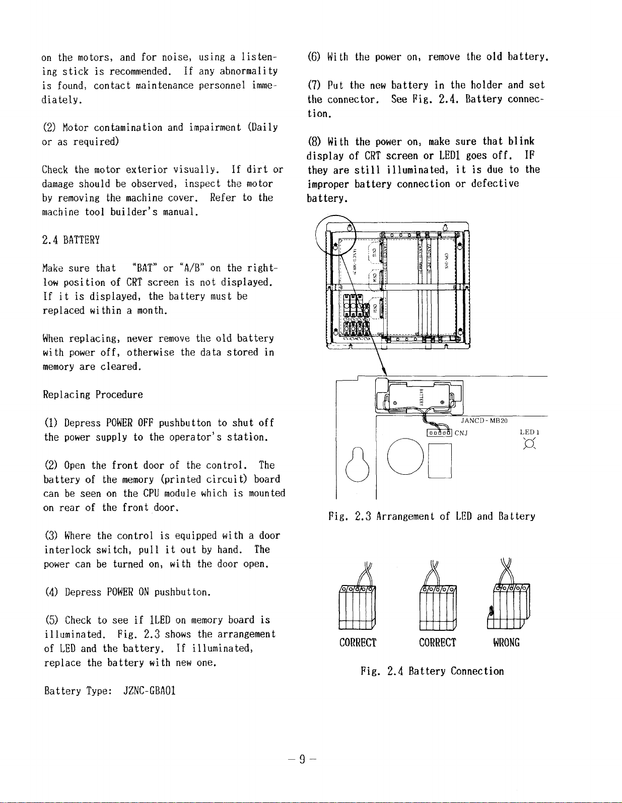
(6) With the power on, remove the old battery.
(7) Put the new bat tery in the holder and set
the connector.
See Fig. 2.4. Battery connec-
tion.
Y
(8) With the power on, make sure that b] ink
display of CRTscreen or LED1goes off. IF
or
they are still illuminated, it is due to the
improper battery connection or defective
battery.
—
\
*\
,+
A -1
Whenreplacing, never remove the old battery
with power off, otherwise the data stored in
memoryare cleared.
Replacing Procedure
(1) Depress POWEROFFpushbutton to shut off
the power supply to the operator’s station.
(2) Open the frent door of the control. The
battery of the memory (printed circuit) board
can be seen on the CPUmodule which is mounted
on rear of the front door.
(3) Where the control is equipped with a door
interlock switch, pull it out by hand. The
power can be turned on, with the door open.
(4) Depress POWERONpushbutton.
(5) Check to see if lLED on memoryboard is
illuminated. Fig. 2.3 shows the arrangement
of LEDand the battery.
If illuminated,
replace the battery with new one.
A \
L
I
Fig. 2.3 Arrangement of LEDand Battery
CORRECT
Fig. 2.4 Battery Connection
CORRECT
WRONG
Battery Type: JZNC-GBAO1
–9-
Page 16
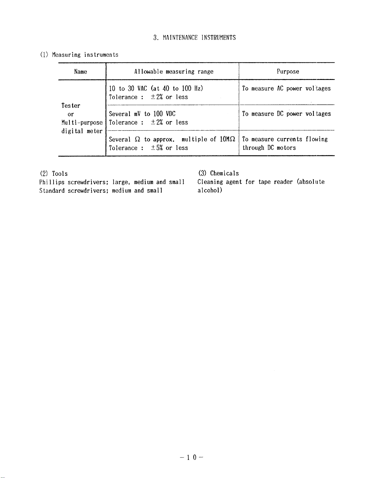
(1) Measuring instruments
3. MAINTENANCEINSTRUMENTS
Name
10 to 30 VAC(at 40 to 100 Hz)
Tolerance :
Tester
or
Multi-purpose
digital meter
(2) Tools
Phillips screwdrivers; large, medium and small
Standard screwdrivers; medium and small
Several mVto 100 VDC
Tolerance :
Several Q to approx.
Tolerance :
Allowable measuring range
~~~ or less
~~~ or less
*5% or less
Purpose
To measure ACpower voltages
To measure DCpower voltages
multiple of 10MQ
(3) Chemicals
Cleaning agent for tape reader (absolute
alcohol)
To measure currents flowing
through DCmotors
–lo-
Page 17
4. TROUBLESHOOTING
4.1 TROUBLE
Try to fully
which the trouble occurred. This is necessary
for identifying the trouble and/or for having
the YASNACservice personnel called in to
correct the trouble.
points will minimize
system:
4.1.1 RECOGNITIONOF
(1) What operation w
(Is other opera t ion performed normal lY?)
(2) Whendoes the trouble occur: every time
or frequently?
(3) Was there no external disturbance such as
power interruption or lightning when trouble
occurred?
(4) Did it occur during or after operation of
mode switches such as EDITor memory, or func-
tion such asm(parameter) or~(diagnose)
or key switch on CRTpanel?
(5) Ensure the fol lowing points if the trouble
occurred as related to feed and/or spindle
operation:
. Check of LEDon the drive unit
. ON/OFFcheck of fuse or MCCB
“ Time of trouble occurrence such as
power application.
at
at
acceleration.
at
deceleration.
at
steady-state running.
(6) Does it depend on part program?
If so, record also part program, offset and
coordinate system settings.
DENTIFICATION
analyze the circumstances in
Verifying the following
the down time of your
TROUBLESTATUS
11 cause the trouble?
recognize the status of
regardless of the detai
The NCunit is provided
switch. When the operator opens the door, the
NCunit power supply is tripped by MCCBand
the interlock switch is released.
Do not start the check operation until the
interlock switch is released.
(1) Nameof
(2) Time of
(3) Nameand type of machine
(4) Nameand type of NCunit and others
(Example)
NCunit
Servo drive : CACR-SR053SB
Servo motor : USAFED-05MA
Spindle drive
Spindle motor
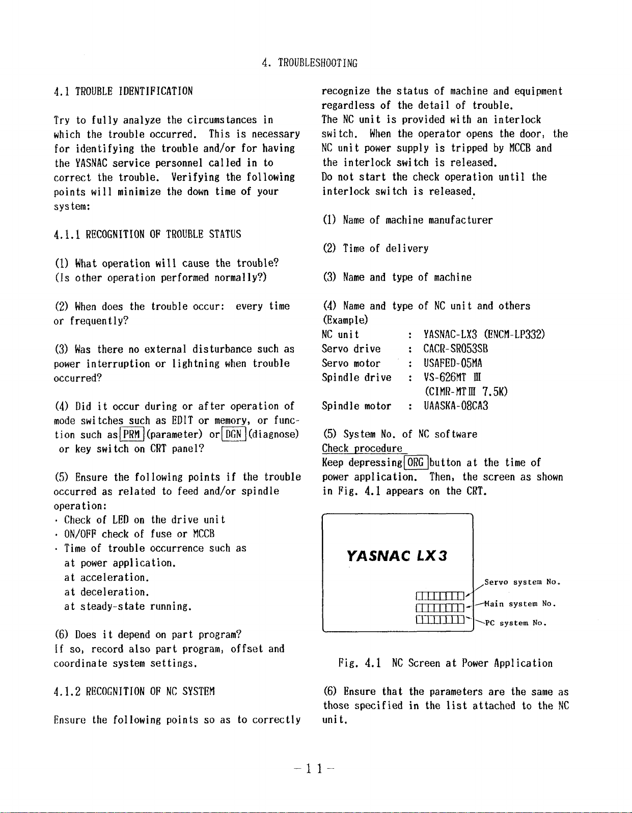
(5) SYStem No. of NCsoftware
Check procedure
Keep depressing~button at
power application. Then, the
in Fig. 4.1 appears on the CRT.
Fig. 4.1 NCScreen at Power Application
machine manufacturer
delivery
: YASNAC-LX3(ENcM-LP332)
: VS-626MTIII
: UAASKA-08CA3
Lx 3
IrrImn Lain sy~tem No
uuuln!nnnn’
1
machine and equipment
of trouble.
with an interlock
(CIMR-MTIII7.5K)
the time of
screen as shown
\
I
Servo system No.
.
~PC system No.
4.1.2 RECOGNITIONOF NCSYSTEM
Ensure the following points so as to correctly
(6) Ensure that the parameters are the same as
those specified in the list attached to the NC
unit.
–11--
Page 18
4+~ TR~U~LESj]()()’TINGBy ALAf/MCODES
This description covers the troubles displayed
by alarm codes that were recognized by diagnos-
tic function of NCunit during normal operation.
Refer to Appendix 1
“List of Alarm Codes.”
Some additional explanations are given for
especially difficult troubles.
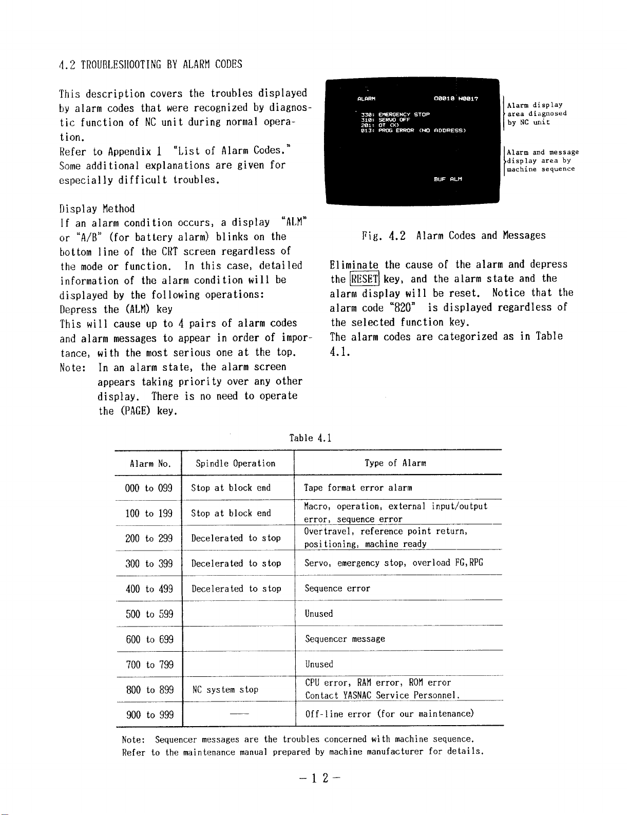
Display Method
If an alarm condition occurs, a display “ALM”
or “A/B” (for battery alarm) blinks on the
bottom line of the CRTscreen regardless of
the mode or function.
In this case, detailed
information of the alarm condition will be
displayed by the following operations:
Depress the (ALM)key
This will cause up to 4 pairs of alarm codes
and alarm messages to appear in order of impor-
tance,
Note:
with the most serious one at the top.
In an alarm state, the alarm screen
appears taking priority over any other
display.
There is no need to operate
the (PAGE)key.
Alarm di splay
area diagnosed
by NC unit
Alarm and message
display area by
machine sequence
Fig. 4.2 Alarm Codes and Messages
Eliminate the cause of the alarm and depress
the=l key, and the alarm state and the
alarm display will be reset. Notice that the
alarm code ‘820”
is displayed regardless of
the selected function key.
The alarm codes are categorized as in Table
4.1.
AlarmNo.
000 to 099
100 to 199
200 to 299
300 to 399
400 to 499
500 to 599
600 to 699
700 to 799
800 to 899
900 to 999 I
Table 4.1
Spindle Operation Typeof Alarm
Stop at block end Tape format error alarm
Stop at block end
Decelerated to stop
Decelerated to stop
Decelerated to stop
I
I
Macro, operation, external input/output
error,
sequence error
Overtravel, reference point return,
positioning, machineready
Servo, emergency stop, overload FG,RPG
Sequence error
I
Unused
i
Sequencermessage
,
I
NCsystem stop
1
Unused
I
CPUerror, RAMerror, ROMerror
Contact YASNACService Personnel.
] Off-line error (for our maintenance)
Note:
Refer to the maintenance manual prepared by machine manufacturer for details.
Sequencer messages are the troubles concerned with machine sequence.
–12-
Page 19
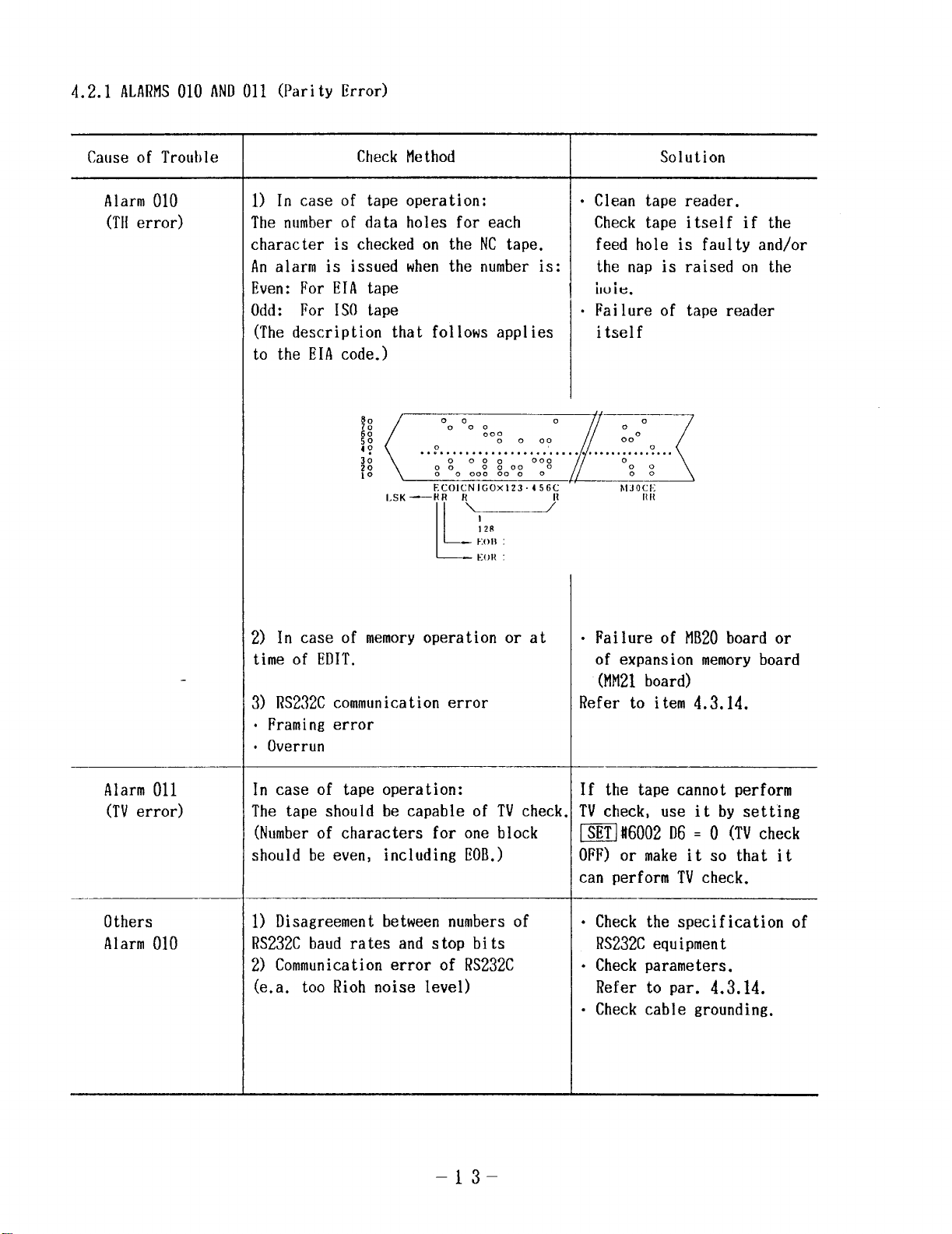
4.2.1 ALARMS010 ANDO1l (Parity Error)
Cause of Trouble
Alarm 010
(THerror)
Check Method
1) In case of tape operation:
The number of data holes for each
character is checked on the NC tape.
An alarm is issued when the number is:
Even: For EIA tape
Odd: For 1S0 tape
(The description that follows applies
to the EIA code.)
!Wr,ca
LSK-RR R
Ec01cNIGox123.456c hlJOCl;
II +
128
ton :
k
E(JR :
Solution
● Clean tape reader.
Check tape itself if the
feed hole is faulty and/or
the nap is raised on the
iluie.
. Failure of tape reader
itself
Tn
HII
Alarm 011
(TVerror)
Others
Alarm 010
2) In case of memoryoperation or at
time of EDIT.
3) RS232C communication error
● Framing error
. Overrun
In case of tape operation:
The tape should be capable of TVcheck
(Number of characters for one block
should be even, including llOB.)
1) Disagreement between numbers of
RS232Cbaud rates and stop bits
2) Communicantion error of RS232C
(ea. too Rioh noise level)
.
Failure of MB20board or
of expansion memory board
(MI121board)
Refer to item 4.3.14.
If the tape cannot perform
TVcheck, use it by setting
m ft6002 D6 = O (TVcheck
OFF) or make it so that it
can perform TVcheck.
● Check the specification of
RS232Cequipment
● Check parameters.
Refer to par. 4.3.14.
“ Check cable grounding.
–13-
Page 20
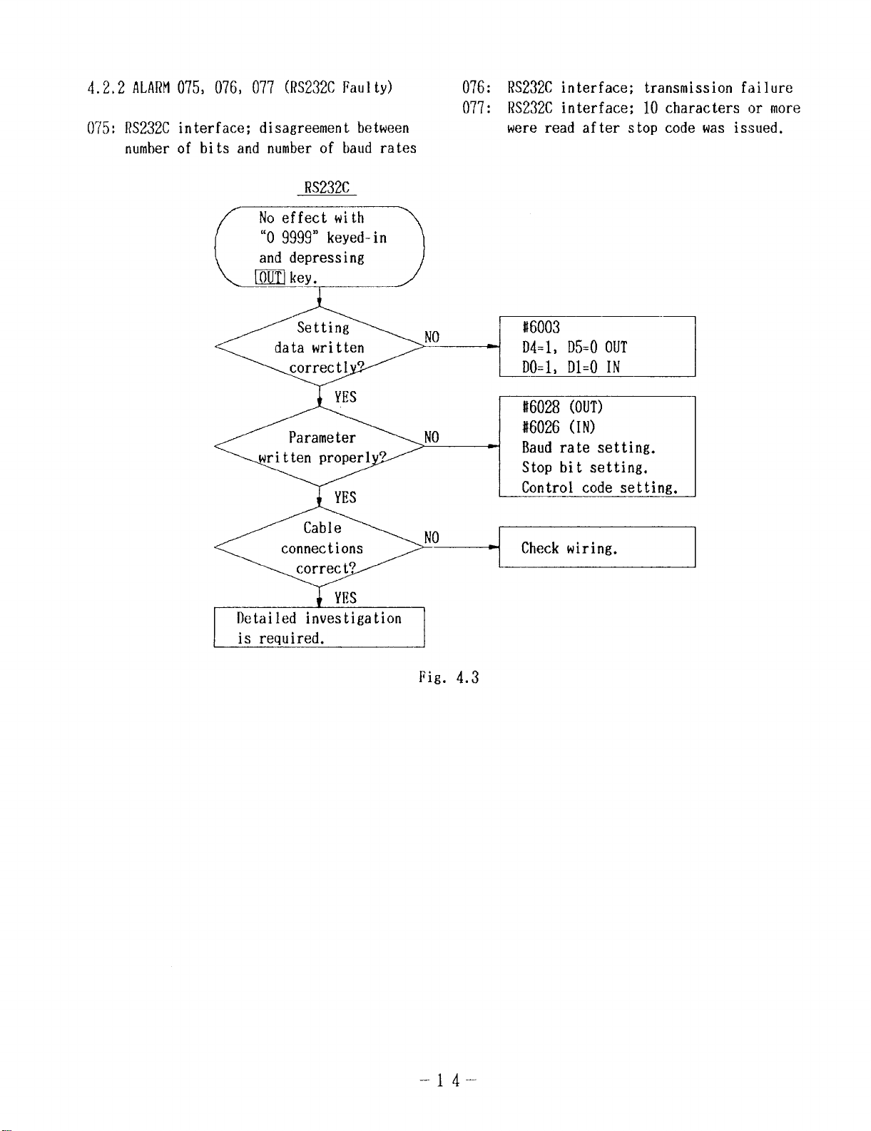
4.2,2 ALARM075, 076, 077 (RS232CFaulty)
075: RS232C interface; disagreement between
number of bits and number of baud rates
RS232C
076: RS232C interface; transmission fi~ilure
077: RS232C interface; 10 characters or more
were read after stop code was issued.
~llkey. ~
—
Setting
data written
~No “ __!ti
correctl 9
NO
\- “-
Fig. 4.3
#6028 (OUT)
#6026 (IN)
Baud rate setting.
Stop bit setting.
Control code setting.
Check wiring.
–14-
Page 21
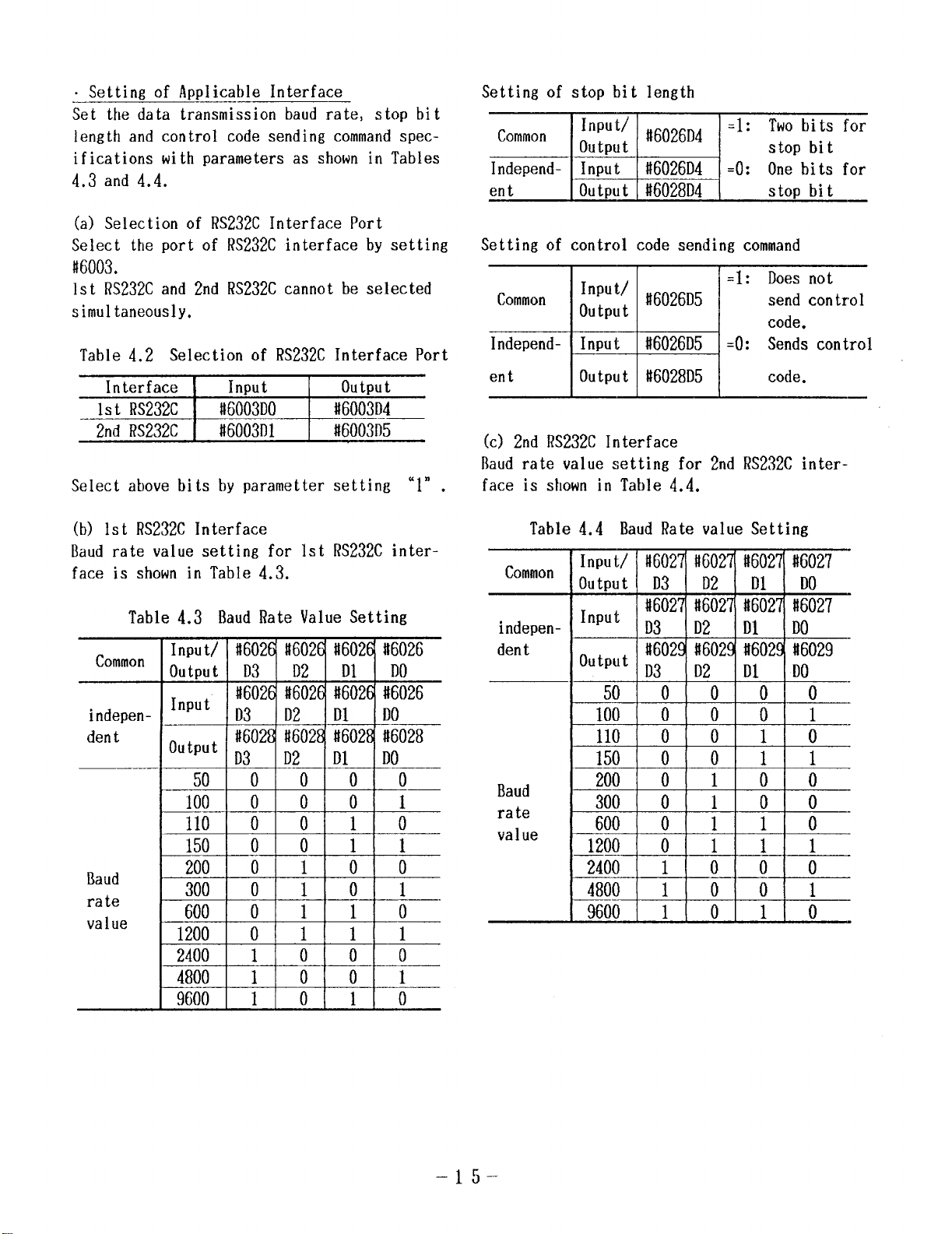
o Settin~ of Amlicable Interface
Set the data transmission baud rate, stop bit
length and control code sending commandspecifications with parameters as shown in Tables
4.3 and 4.4.
(a) Select ion of RS232C Interface Port
Select the port of RS232C interface by setting
#6003.
1st RS232Cand 2nd RS232Ccannot be selected
simultaneously.
Table 4.2 Selection of RS232CInterface Port
Interface
1st RS232C
2nd Rs232C
Select above bits by parameter setting ‘1” .
Input
#6003D0 #6003D4
#6003f)l
Output
#6003D5
Setting of stop bit length
Setting of control code sending command
I
Common
Independentt
(c) 2nd RS232C Interface
Baud rate value setting for 2nd RS232C inter-
face is shown in Table 4.4.
input’#6026D5
output
Output #6028D5
I
=1: Does not
send control
code.
=0: Sends control
code.
(b) Ist RS232C Interface
Baud rate value setting for 1st Rs232C inter-
face is shown in Table 4.3.
Table 4.3 Baud Rate Value Setting
Common
indepen-
dentt
Baud
rate
value
Input/
output
‘nput
‘u ‘Put
Jo
110
150
200
300
600
#6026 li6026 it602E it6026
D3 D2 D1 DO
#6026 #6026 #6026 #6026
D3 D2 D1 DO
#602/?’#6028 #6028 #6028
D3 D2 D1 DO
50
0 0 0 0
o 0
0 0 1 0
0 0 1 1
0 1 0 0
0 1 0 1
0 1 1 0
0 1
Table 4.4 Baud Rate value Setting
Common
indepen-
dentt
Baud
rate
value
Input/
Output
Input
output
100
110
150
200
300
600
1200
2400
4800
9600
t1602~#602~ #602~ #6027
—
50
#&i&
iEHEk
–lrj _
Page 22
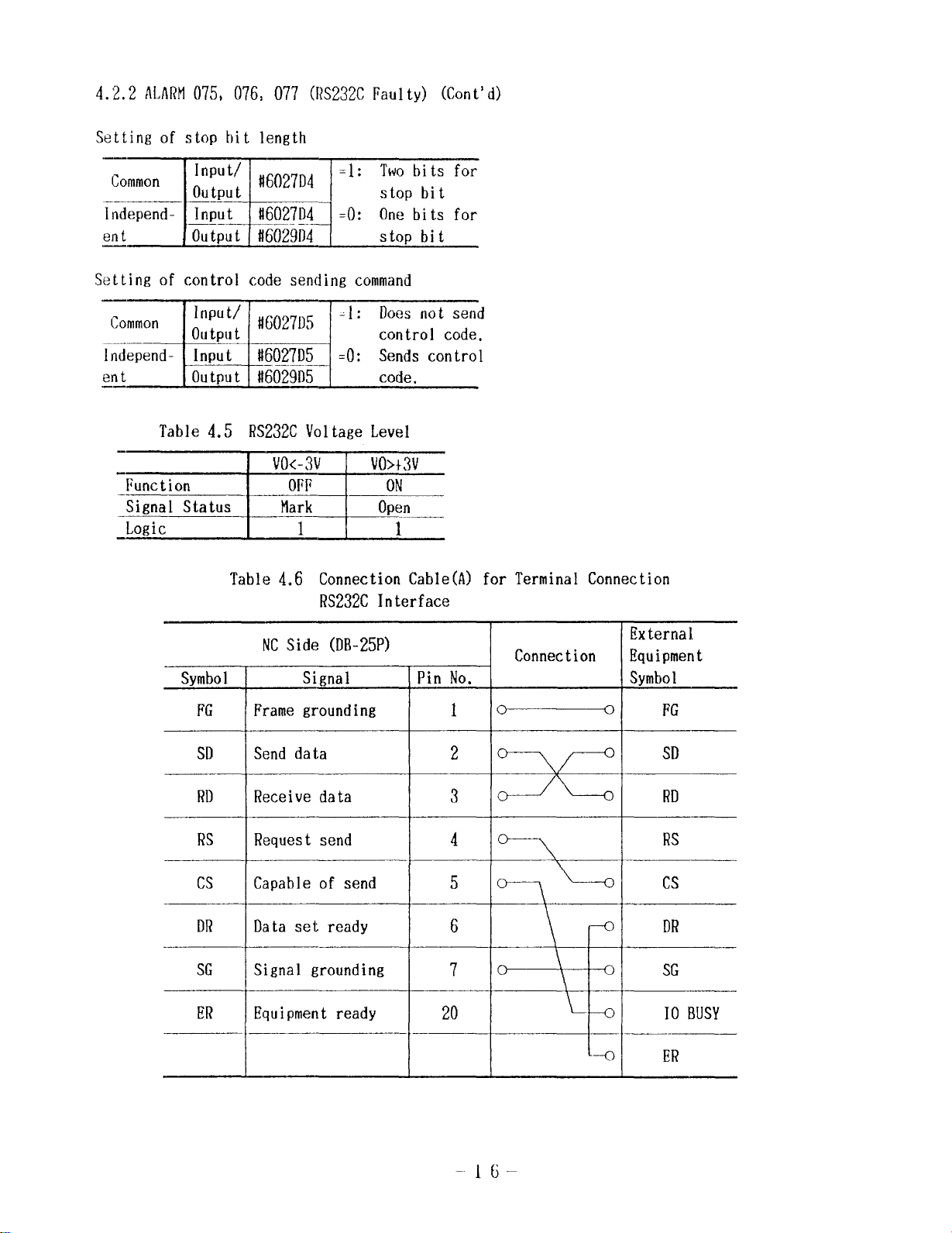
4.2.2 ALARM075, 076, 077 (RS232CFaulty) (Cont’ d)
Setting of stop bit length
—
Common
lndepend- Input !16027D4 =0: One bits for
ent Out;ut
Setting of control code sending command
Function
‘Signal Status
—
_Logic
input’ #6027D4
output
#6029D4 stop bit
Table 4.5 RS232CVoltage Level
VO<-3V VO>+3V
I
OFF ON
Mark Open
I
=1: Twobits for
1 -[
stop bit
1“
Table 4.6 Connection Cable (A:
RS232C Interface
NCSide (DB-25P)
Symbol
FG Frame grounding
SD
RD Receive data
RS Request send
Cs Capable of send
DR Data set ready
SG Signal grounding
ER
I
Send data
Equipment ready
Signal
\
Connection
External
o
*
— ..—.
+
for Termina
Connection Equipment
]Pin No. Symbol
1~
I
2
3
4
5
6
7
20
—,—
0
FG
SD
RD
RS
SG
10 BUSY
ER
16
Page 23
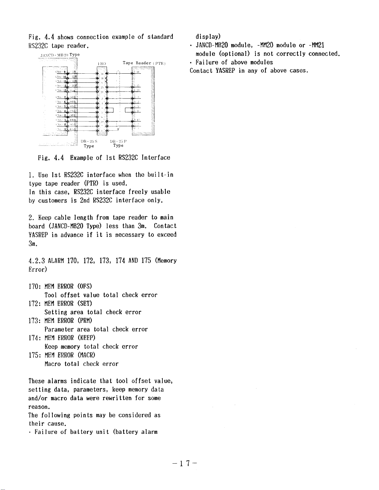
Fig. 4.4 Example of 1st RS232C Interface
1. Use 1st RS232Cinterface when the built-in
type tape reader (PTR) is used.
In this case, RS232Cinterface freely usable
by customers is 2nd RS232C interface only.
display)
“ JANCD-MB20module,
-MM20module or -MM21
module (optional) is not correctly connected.
● Failure of above modules
Contact YASREPin any of above cases,
2. Keep cable length from tape reader to main
board (JANCD-MB20Type) less than 3m. Contact
YASREPin advance if it is necessary to exceed
3m.
4.2.3 ALARM170, 172, 173, 174 AND175 (Memory
Error)
HEMERROR(OFS)
170:
Tool offset value total check error
MEtlERROR(SET)
172:
Setting area total check error
MEMERROR(PRM)
173:
Parameter area total check error
MEMERROR(KEEP)
174:
Keep memory total check error
MEMERROR(MACR)
175:
Macro total check error
These alarms indicate that tool offset value,
setting data, parameters, keep memorydata
and/or macro data were rewritten for some
reason.
The following points may be considered as
their cause.
. Failure of battery unit (battery alarm
–17-
Page 24
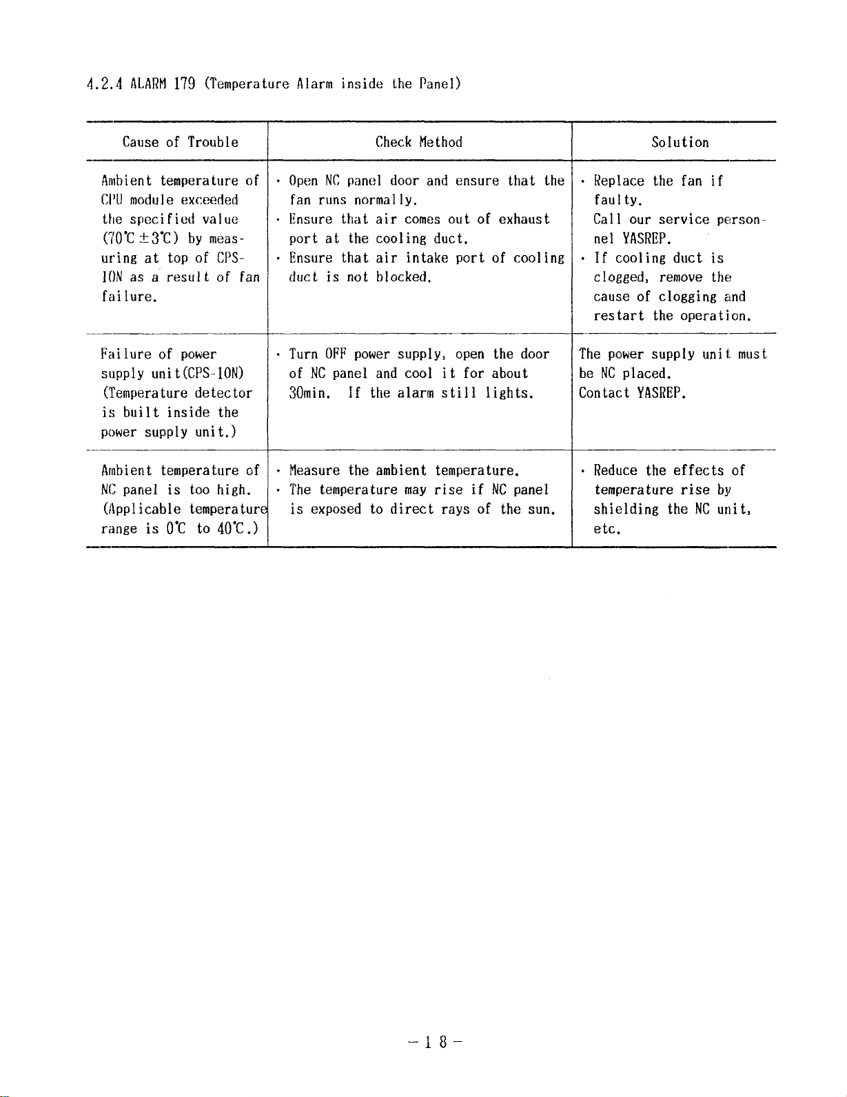
4.2.4 flLARtl179 (Temperature Alarm inside the Panel)
Cause of Trouble
Ambient temperature of
CI)Umodule exceeded
the specified value
(70”Ct3”C) by meas-
uring at top of CPS10N as a result of fan
failure.
Failure of power
supply unit(CPS-10N)
(Temperature detector
is built inside the
power supply unit.)
_——
Ambient temperature of
NCpanel is too high.
(Applicable temperature
range is O-C to 40”C.)
Check Method
.
Open NCpanel door and ensure that the
fan runs normally.
.
Ensure that air comes out of exhaust
port at the cooling duct.
.
Ensure that air intake port of cooling
duct is not blocked,
—
“ Turn OFF power supply, open the door
of NCpanel and cool it for about
30min.
If the alarm still lights.
“ Measure the ambient temperature.
“ The temperature may rise if NCpanel
is exposed to direct rays of the sun.
Solution
o Replace the fan if
faulty.
Call our service personnel YASRllP.
● If cooling duct is
clogged, remove the
cause of clogging and
restart the operation.
The power supply unit must
be NCplaced.
Contact YASREP.
o Reduce the effects of
temperature rise by
shielding the NCunit,
etc.
–18–
Page 25
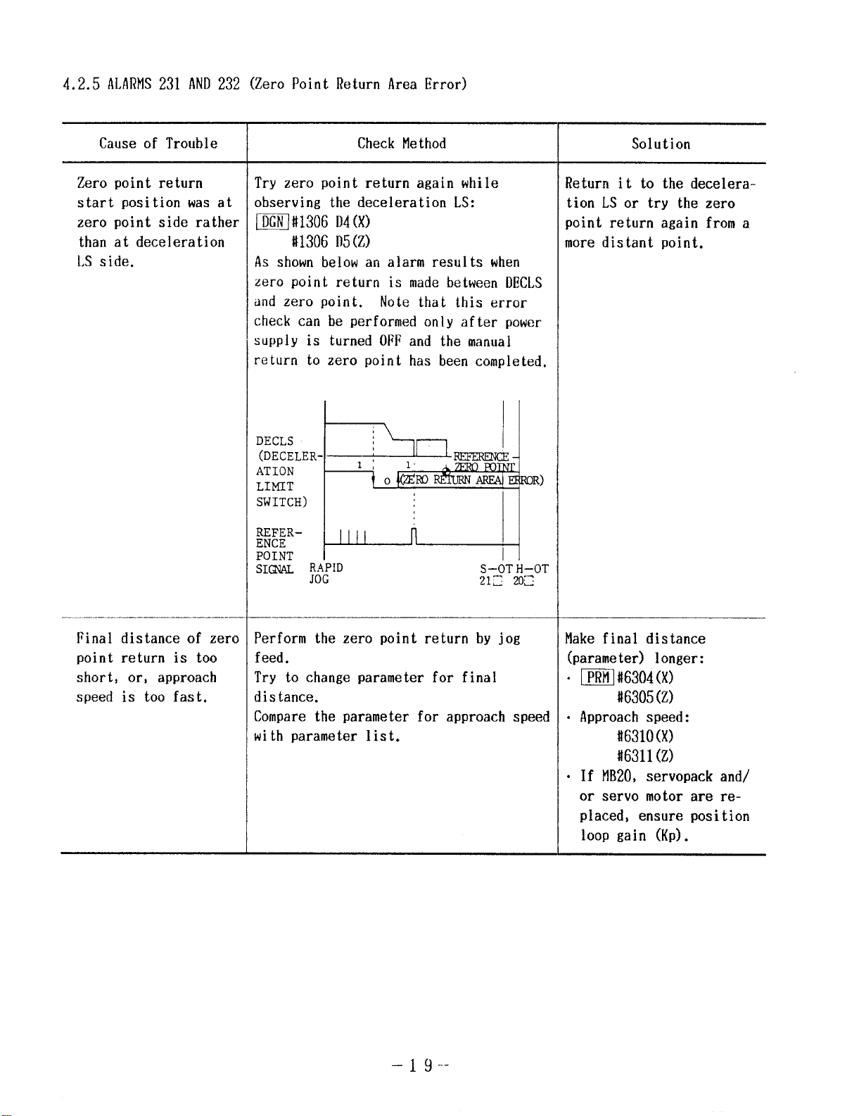
4.2.5 ALARM231 AND232 (Zero Point Return Area Error)
Cause of Trouble
Zero point return
start position was at
zero point side rather
than at deceleration
LS side.
Check Method
Try zero point return again while
observing the deceleration LS:
~#1306 D4(X)
#1306 D5(Z)
As shown below an alarm results when
zero point return is made between DECLS
and zero point.
Note that this error
check can be performed only after power
supply is turned OFFand the manual
return to zero point has been completed.
SWITCH)
Solution
Return it to the decelera-
tion LS or try the zero
point return again from a
more distant point.
Final distance of zero
point return is too
short, or, approach
speed is too fast.
!%!:-L-L
SI@J& R#D
S–OT
212. ;
Perform the zero point return by jog
feed.
Try to change parameter for final
distance.
Compare the parameter for approach speed
with parameter list.
Make final distance
(parameter) longer:
. m#6304(X)
116305(Z)
● Approach speed:
#6310(X)
+16311(Z)
● If MB20,servopack and/
or servo motor are replaced, ensure position
loop gain (Kp).
–l(J._
Page 26
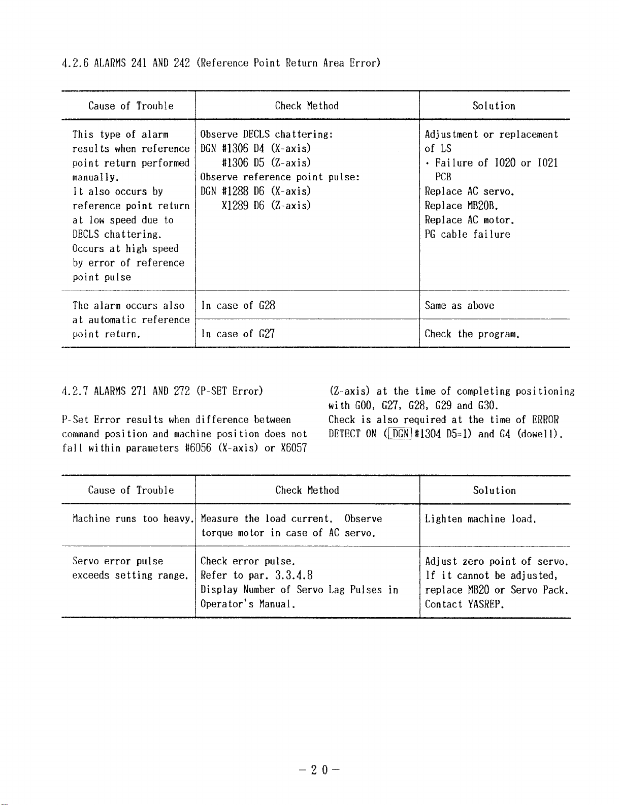
4.2,6 ALARMS241 AND242 (Reference Point Return Area Error)
Cause of Trouble
This type of alarm
results when reference
point return performed
manually.
It also occurs by
reference point return
at low speed due to
DECLSchattering.
Observe DECLSchattering: Adjustment or replacement
DGN#1306 D4 (X-axis) of LS
#1306 D5 (Z-axis)
Observe reference point pulse: PCB
DGN#1288 D6 (X-axis) Replace ACservo.
X1289 D6 (Z-axis) Replace MB20B.
Check Method
I
● Failure of 1020 or 1021
Solution
Replace ACmotor.
PG cable failure
Occurs at high speed
by error of reference
point pulse
The alarm occurs also
In case of G28 Same as above
at automatic reference
point return.
4.2,7 ALARMS271 AND272 (P-SET Error)
In case of G27 Check the program.
(Z-axis) at the time of completing positioning
with GOO,G27, G28, G29 and G30.
[)-Set Error results when difference between Check is also required at the time of ERROR
commandposition and machine position does not DETECTON (~#1304 D5=1) and G4 (dowell).
fall within parameters #6056 (X-axis) or X6057
Cause of Trouble Check Method
Miichine runs too heavy. Measure the load current. Observe
torque motor in case of ACservo.
Servo error pulse
exceeds setting range.
Check error pulse.
Refer to par. 3.3.4.8
Display Number of Servo Lag Pulses in
Operator’s Manual.
-20–
Solution
Lighten machine load,
Adjust zero point of servo.
If it cannot be adjusted,
replace MB20or Servo Pack.
Contact YASREP.
Page 27
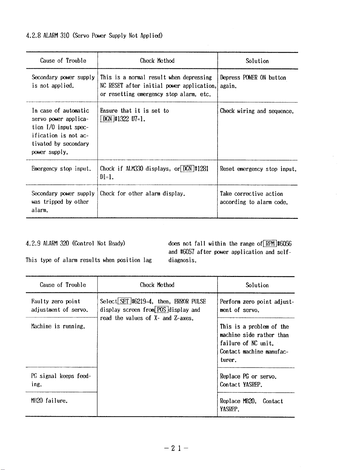
4.2.8 ALARM310 (Servo PowerSUPPlYNot APP1ied)
Cause of Trouble
Secondary power supply
is not applied.
In caseof automatic
servo power applic-
ation 1/0 input specification is not activated by secondary
power supply.
Emergencystop input.
Secondary powersupply
was tripped by other
alarm.
Check Method
This is a normal result whendepressing
NCRESETafter initial ~r application
or resetting emergency stop alarm, etc.
Ensure that it is set to
~#1322 D7=l.
Chwk if ALht330displays, or~l!ll?lll
Dl=l.
Check for other alarm display.
Solution
Depress IWERONbutton
again.
Check wiring and sequence.
Reset emergency stop input.
Take corrective action
according to alarm code.
4.2.9 ALARM320 (Control Not Ready)
This ty~of alarm results whenposition lag
Cause of Trouble
Faulty zero point
adjustment of servo.
Machine is running.
PCsignal keeps feeding.
MIMIfailure.
Wctm!%219=4, then, ERRORPULSE
iisplay screen from~display and
wad the values of X- and Z-axes.
Check Method
does not fall within therangeofmM056
and it6057 after powr application and selfdiagnosis,
Solution
Perform zero Wint adjust-
ment of servo.
This isaproblmof the
machine side rather than
failure of NCunit.
Contact machine manufac-
turer.
Replace FCor servo.
Contact YASREP.
Replace MB20. Contact
YASREP.
–21-
Page 28
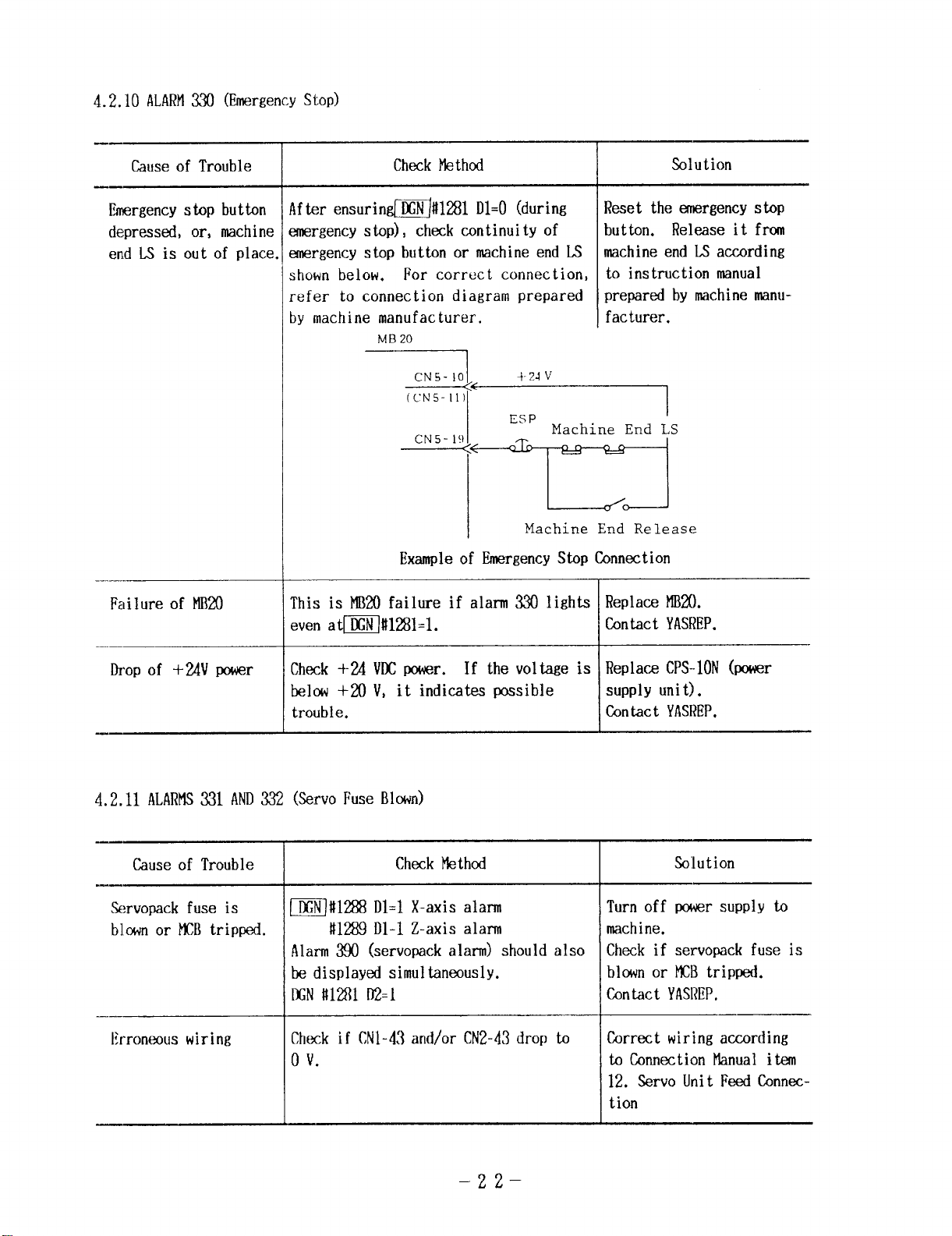
4.2.10 ALARM330 (EmergencyStOP)
——
Cause of Trouble
CheckMethod
Solution
Emergencyshp button
depressed, or, machine
end L-Sis out of place
Failureof MIMI
!fter ensurinm#1281 D1=O(during
anergency stop), check continuity of
mergency stop button or nnchine end LS
shown below. For correct connection,
refer to connection diagram prepared
by math ne manufacturer.
MB20
1
ESP
Machine End LS
“ m
L--%--J
Machine End Release
Exampleof EmergencyStop Connection
This is MB2Qfailure if alarm 330 lights
even amgli%l=l.
Reset the emergency stop
button. Release itfrcrn
machine end LS according
to instruction manual
prepared by machine manu-
facturer.
I
Replace HB20.
Contact YASREP.
Drop of +24V power
Check +24 VDCpower. If thevolt.age is
below +20V, it indicates pmsible
trouble.
4.2.11 ALARMS331 AND332 (.ServoFuseBlown)
Cause of Trouble
Servopack fuse is
bl.wn or~B tripped.
I
m#1288 Dl=l X-axis alarm
#1289 D1-1 Z-axis alarm
Check Methcxl
Alarm3!%)(servoPack alarm) should also
be displayed simultaneously.
IXN#1’281D2=l
Erroneous wiring
Check if CN1-43and/or CN2-43drop to
o vi
Replace CPS-10N(power
supply unit).
Contact YASREP.
Solution
Turn off power supply to
mathine.
Check if servopack fuse is
blcm or KB tripped.
Contact YASREP.
Gm-ect wiring according
toconnection f’lanualitem
12. Servo Unit Feed Ca-mction
–22–
Page 29
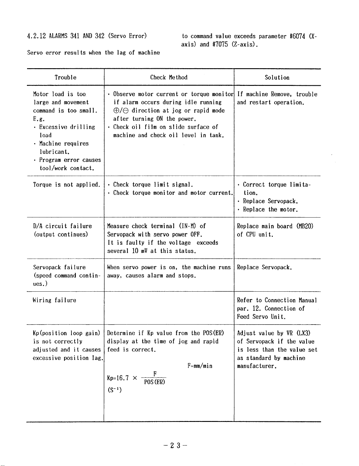
4.2.12 ALARMS341 AND342 (Servo Error)
Servo error results when the lag of machine
to commandvalue exceeds parameter #i6074 (X-
axis) and #7075 (Z-axis).
Trouble
Motor load is too
large and movement
commandis too small.
E.g.
“ Excessive drilling
load
● Machine requires
lubricant.
“ Program error causes
tool/work contact.
Torque is not applied.
D/A circuit failure
(output continues)
Check Method
.
Observe motor current or torque monito;
if alarm occurs during idle running
@/t3 direction atjogor rapid mode
after turning ONthe power.
.
Check oil film on slide surface of
machine and check oil level in tank.
—
● Check torque limit signal.
● Check torque monitor and motor current
Measure check terminal (IN-M) of
Servopack with servo power OFF.
It is faulty if the voltage exceeds
several 10 mVat this status.
Solution
If machine Remove, trouble
and restart operation.
● Correct torque limita-
tion.
● Replace Servopack.
“ Replace the motor.
Replace main board (MI120)
of CPUunit.
Servopack failure
(speed commandcontin-
ues. )
Wiring failure
Kp(position loop gain)
is not correctly
adjusted and it causes
excessive position lag
Whenservo power is on, the machine runs
away, causes alarm and stops.
Determine if KP value from the POS(ER)
display at the time of jog and rap’
d
feed is correct.
F=mm/min
F
‘P=16”7 x POS(ER)
(s-’)
Replace Servopack.
Refer to Connection Manual
par. 12. Connection of
Feed Servo Unit.
Adjust value by VR (LX3)
of Servopack if the va
is less than the value
ue
set
as standard by machine
manufacturer.
–23–
Page 30
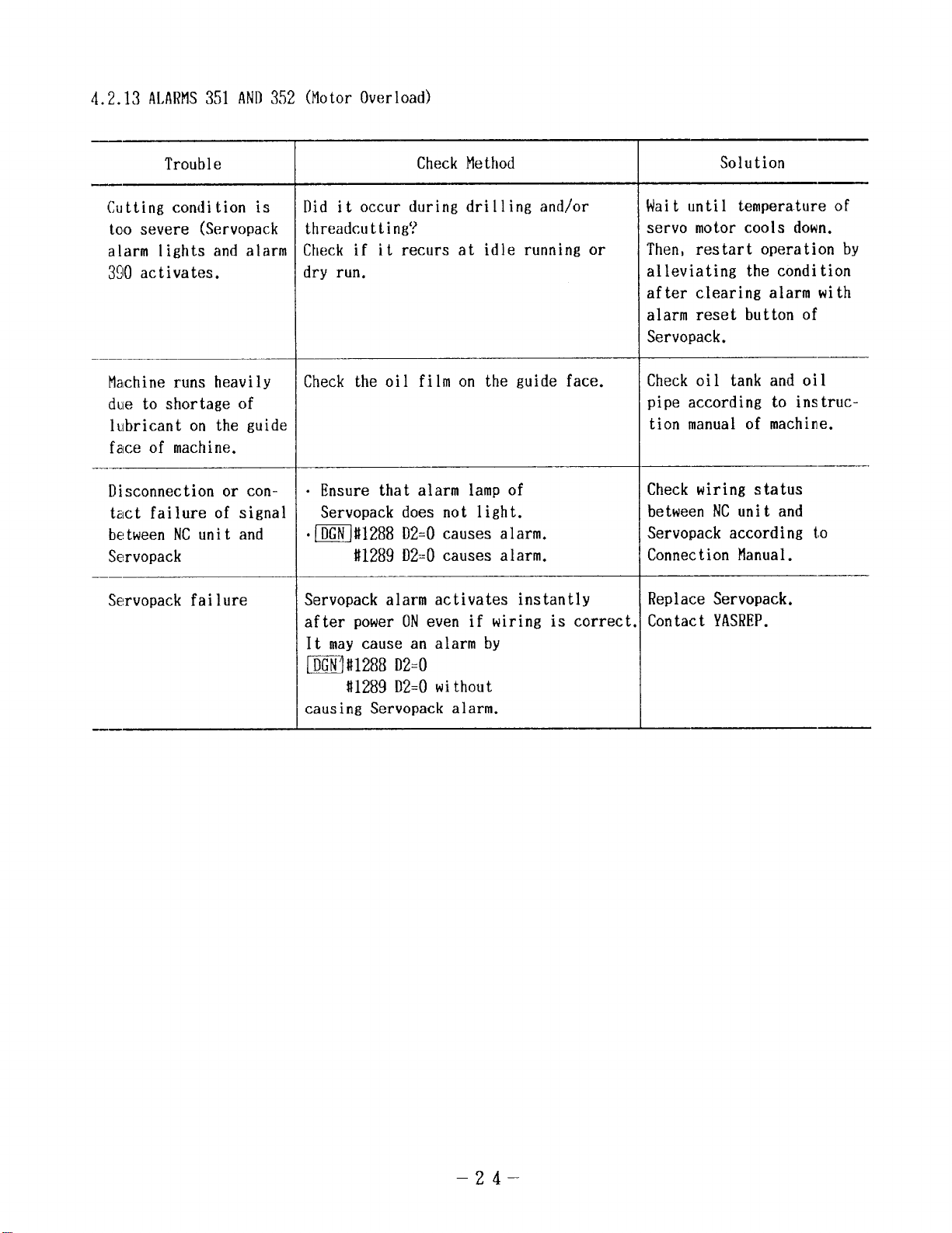
4.2.13 ALARMS351 AND352 (Motor Overload)
Trouble
Cutting condition is
too severe (Servopack
alarm lights and alarm
390 activates.
Ma(chineruns heavily
due to shortage of
lubricant on the guide
face of machine.
———
Disconnection or con-
tact failure of signal
between NCunit and
Servopack
!%!rvopack failure
Check Method
Did it occur during drilling and/or
threadcutt.ing?
Check if it recurs at idle running or
dry run.
Check the oil film on the guide face.
“ Ensure that alarm lamp of
Servopack does not light.
.~#1288D2=0 causes alarm.
#1289 D2=0 causes alarm.
Servopack alarm activates instantly
after power ONeven if wiring is correct
It may cause an alarm by
m#1288 D2=0
#1289 D2=0 without
causing Servopack alarm.
Solution
Wait until temperature of
servo motor cools down.
Then, restart operation by
alleviating the condition
after clearing alarm with
alarm reset button of
Servopack.
Check oil tank and oil
pipe according to instruc-
tion manual of machine.
Check wiring status
between NCunit and
Servopack according to
Connection Manual.
Replace Servopack.
Contact YASREP.
–24–
Page 31

4.2.14 ALARMS361, 362 AND366 (PG Disconnection Error)
They perform 2 types of checkup: Signal wire
disconnection check of A, B and C phases from
PG and check by PG input comparison at the
time when TGONsignal from Servopack turns ON.
Trouble
Disconnection or
contact failure of
signal wire between NC
unit and servopack
Failure of PG detector
circuit connection
No shorting plug connector even without
spindle PG.
Servopack failure
Check Method
.
Check for looseness and removal of
MB20board’s connectors CN1 (X-axis),
CN2(Z-axis), CN3(spindle) and/or
CN4(spindle PG).
.
Check looseness and removal of
Servopack connectors.
.
Perform wiring check according to
Connection Manual.
—
This type of alarm results when main
power is applied though result of check
for above item 1 is normal.
Shorting plug connector to CN4at CPU
module is required for such specifica-
tions without spindle PG.
● Check if
m#1288 D7=1
(X-axis TGON)
#1289 D7=1
(Z-axis TGON)
occur at motor stop.
“ If alarm occurs above the speed to
turn ONTGONsignal, it may be PG
output signal failure of Servopack.
Solution
● Correct looseness and/or
removal of connectors.
“ Correct wiring as neces-
sary.
Replace MB20.
Contact YASREP.
Mount shorting plug
connector.
Replace Servopack.
PG failure
Setting failure of
TGONsignal detect
level for Servopack
(Abnormal case)
“ If alarm occurs above the speed to
turn ONTGONsignal, it may be failure
of PG.
This type of alarm results when position
detector PPS is low. Motor may reach
running speed at TGONsignal detect
level in case of a large speed change
ratio with an external detector (such as
Inductosyn, linear scale).
–25–
Replace PG
This is a rare case.
But, change TGONsignal
detect level of servopack
to 12%from the standard
~.
Page 32

4.2.15 ALARM325 (Servo CPUError)
Trouble
Servo CPUfailure
4.2.16 ALARM329(Buil t-in type PC CPUerror)
Cause of Trouble
PC CPUfailure
4.2.17 ALARM820 (ROM/RAMCheck Error)
It performs check of ROMconstantly and RAMat
the time of power application with self-
diagnostic function of NCunit. If there is
mflfi014 D6=1 causes error.
I
m#6014 D7=1 causes error.
Check Method Solution
Check Method
Replace MB20.
Contact YASREP.
Solution
Replace PC20.
Contact YASREP.
any fault, it is displayed together with RO1l/
RAMnumber.
This is one of the major failures. After recording the alarm number, immediately contact
YASREP.
Trouble
#00 to #05 ROMin
failure
#30, #33 ROMerror MM-20 ERROR
#350 RAMerror PCURAMtiERROR
#36 ROMerror
I
IIM-20 ERROR
#ON:820
#30 :820
(#33)
$350820
MFI-20ERROR
#36 :820
Check Method
(n=O to5)
Solution
Replace ROM#00 to #05
mounted to MM20.
Replace ROM#30(#33)
mounted to MM20.
Failure of RAMmounted to
PC20
Replace PC20.
Replace ROM#36 mounted to
Mf120.
–26–
Page 33

Trouble
Check Method
Solution
#500 RAMerror
#40 error
#44, 45 error
#100 to#103 RAMfailure
#120 RAMfailure
#300 to #301 RAMfailure
#302 RAMfailure
#510 to #511, #520,
#521, #530 RAMfailure
RAMCHECKERROR
#0500 820
(#501)
PC-ROMUERROR
#40 :820
MB-20 ERROR
#44 :820
(i145)
RAMCHECKERROR
#XXX:820
RAMCHECKERROR
#XXX:820
Failure of RAMmounted to
MB20
Replace MB20.
Replace ROM#40 mounted to
PC20.
Replace ROM#44(#45)
mounted to MB20.
Replace MM20.
Replace MB20.
Replace PC20.
Replace PC20.
Replace MB20.
4.2.18 ALARM323 (ACGC2SYNCERROR)
Trouble
ACGC2CPU failure
m 116014D5=1causes error.
Check Method
–27–
Solution
Contact YASREP.
Page 34

4.3 TROUBLESHOOTINGWITHOUTALARMCODES
The following examples are instructions for
locating and correcting the troubles not indi-
4.3.1 POWERCANNOTBE SUPPLIED.
cated by alarm codes.
For further details of signal meanings expressed by the address~, refer to Section “Re-
tails of Signals” in Connection Manual.
Trouble
No power SUPP1
unit.
.——
Alarm LEDof CPS-ION
lights.
d to NC
Check Procedure
Ensure that SOURCELED(green) of DC
power SUPP1Y(CPS-1ON)inside CPUmodule
lights.
CPS-IONLEDDisplay
Signal
Naw
Pwer
Norma 1
Trouble
Display
supply
status
Pn+er on
status
v
+5
Trouble
+12 v
Trouble
-12 v
Trouble
+2.4 v
Trouble
External
trouble
Note:
LEDlights for external trouble (EXT) when CN13
connector batwen 4 and 7 short-circuits.
i LED
Display !
IWER ON Grsen
+5 v,
*12
+24v
Color
,
SOURCE ~ Green
Rad
v
Red
EXT Red
Func t ion &
Cause
Lights when AC
pouer is on, out
when owr is
Lights i+hen SOURCE
input above 170
VAC at NC!IXCN.
Lights at +5 V
over- vo 1 tage or
overcurrent.
Lights at +12 V
overvoltage or
–
12 V under-
vol tsge.
Lights at
over- vo 1 tage
overcurren t.
or
Lights with
external EXALtl
signal.
off.
+24 V
Solution
Check molded-case circuit
breaker or NCpanel and
also connector CN13of
CPS-1ON.
When trouble in Table on
the left is displayed by
LED, correct the trouble,
then, turn on power again.
If the trouble is not
corrected by this procedure,
trouble mey be in the power
unit. Contact your YASKAWA
representative(YASREP).
Power ON/OFFSwitch is
not set properly.
SW5
)
i
I0 =
10 I o ~ 12- POF(invalid/valid)
u
(Set at factory
Prior tO
shirment)
I
i 3+ ’14 ‘Cn’y cm)
Use panel (POF)
only
lo~3
~
SW5
7~09
10 o= 12
SW5Setting(for 9 ‘CRT)
1
Use external
device (EOF)
only
000 G
El
I
I
–28–
Use both
Set correctly shorting
plug SW5at left corner on
MB20PCB.
3
6
9
12
Page 35

4.3.2 INITIALDIAGNOSTICERRORDISPLAYATPOWERON
Trouble !
Error identified by
initial diagnostics at
power ON.
4.3.3 “CPUERROR”DISPLAY(Without Alarm Codes)
Trouble
“CPUERROR”only is
displayed on CRT
screen.
Both diagnostic items passed and
diagnostic item lead up to error are
displayed and NCunit stops.
I
CPUcannot function normally and this is
major failure. The main system shuts
off th6 servo power, but, depress the
emergency stop and power OFF buttons to
make check for proper AC input voltage
and ensure power is OFF.
Check Procedure
Check Procedure
I
Record the diagnostic item
lead up to NCunit stop,
turn on power again and
contact your YASKAWArepresentative of its results.
I
Removeany noise source
near the NCunit.
Turn on the main power
under emergency stop
condition.
YASKAWArepresentative
immediately if it is “CPU
ERROR”.
If normal, start operation
after ensuring correct
parameters, settings, offsets and programs.
Solution
Solution
Contact our
–29-
Page 36

4.3.4 CRTSCREENDOESNOTDISPLAY
CRTscreen may not display any data as a result
of trouble of CRTunit itself, display circuit
and/or connection cable.
If there is no display on the screen even after
the NCunit power is applied, check to ensure
4.3.5 HANDLEMODEOPERATIONFAULTY
that the wire is properly connected to the NC
operator’s station, connectors are not loose,
or fuse inside CRTunit is not blown(refer to
Par. 4.3.12, “ 9“ CRTSCREENIS DARK”).
Contact YASREP,if the trouble can not be lo-
cated even after the above procedure,
Trouble
Handle mode not selec-
tion,
——
Axis not selection.
Magnification not se-
lection.
Check Procedure
~#1300 D,
m#1302 D, (X-axis)
m#1302 D, (Z-axis)
Handle Magnification Setup
#1302 D,
MP3
0
0
0
0
1
#1302 Do
#1302 D7
MP2 MP1 cation
0
0
1 0
1 1
Either Oor 1
is acceptable.
Solution
Check wiring for Proper
mode.
Select the axis.
Check wiring.
llagnifi-
Check sequence.
0
1
xl
x 10
x 100”
Check wiring.
x 100”
x 100
No power to handle PG.
No pulse generated by
turning handle.
Check that +5 V is supplied on
terminal of handle PG.
Also check the signal wiring.
Hanual pulse monitor~#1282 DOto D7
Does this DGNchange by turning handle?
–30-
Correct wiring according
to Connecting Manual(TOE-
c843-9.22) .
Same as above
Page 37

Trouble
Check Procedure
Solution
Parameter not set correctly.
SW1of SP20 not set to
ENB.
m#6222
Max.
1: Magnification to be set with~
0: Magnification XIOO
SW1setup is shown below.
1 HPGpower is fixed to +5 V.
2 SW1on SP20 board is set as below by
speed at handling(Reference)
m#6009 D4
#6223 at handlex 100
specification of manual pulse
generator.
(Swl)
1
Em”
000
4
000
7
000
10
Simultaneous 1 axis manual
pulse generator
3
6
9
12
Set parameter according to
YASNACLX3Operator’s
Manual(TOE-C843-9.20)
Specification for simultaneous 1 axis manual pulse
generator. (Use this
terface.)
–31–
Page 38

4.3.6 MANUALJOG MODEOPERATIONFAULTY
Trouble
Jclg mode not selected
Axial direction not
specified.
Jcg override not enter
ed
_——
Check Procedure
mti1300 D,
+xmIt1302
IIz
–X~~#1302 D3
i-Z~#1302 D4
–z~#1302 D5
Feed override/Hanual JOG feed rate Selection
=
r !6238 Setting speed_
r #6239 Setting speed
110; 0101 80% lPar.ame~r__~241 Setting speed
araaeter t6240
100’0
-+ t--
.1 0-
~o..
.~
l_olo
t
1 ,–03
;-~$+-{--
‘~ 1-::
-f~, ~~
-:”–:7-
-fi+- 1#+-
1
kote: 1: close O: open
g
‘--
0
0 1 170%
_~ j. _
1 1 190 ~
o 0 203%
-;- -;-
-t-
.1-+.1
7—
0
.O+O. Para~ter ~6261 Setting sgeed
,,
1
160 %_
@%__ Para~ter #6251 SettingspSed
araweter
Parawter t6249 %ttings~ed
Parameter #6250 Setting speed
Parameter 16252 %tting speed
Paraweter t6253_%tting speed
Parameter #6254_%tt i ng_s~_ed _
Parawter t6255 Setting sp~d
Pa:?~_tg~
Parameter~Setting speed..
Para~ter t6258 Setting speed
o% Paramter $6259 Setting :_@ed
~- ‘--”-”-”
Parawter
Para.~t::.#6&2.Setting sq?ed_
~a~~m~er *6263 Set t i ng_spwd
, Paramter
Settings&ed
~42 Setting sy@
t6243SettinS_>@
t6244Setting sqd
r
r t6245 .%-
r
t6246Settingj.~d.
r
ffi247 Setting speed
t6248Setting speed
$62EfjSetti “g speed
t62?XlSettig~_:peed
#6264Setting speed
S&_@
Solution
Select the mode.
Check wiring.
Select axial directicm.
Check wiring.
Set jog
value o
Check w
override to move
her
han O.
re.
Parameter not set correctly.
Not at machine lock.
Ensure thatmlt6233 to #6264 are set
according to Table 4.9.
m#1303 D,
–32–
Set parameter
Check the switch to ensure
thatm#6000Dl is at 1.
Page 39

4.3.7 MANUALRAPIDMODEOPERATIONFAULTY
Trouble
Rapid mode not selected.
Axial direction not
specified.
Rapid override not
entered.
Check Procedure
m#1300 DO
+X~#1302 Dz
–X~#1302 DS
+Zm#1302 D4
–Zm#1302 D5
Input status and Rapid feedrate
MNSlzol
Inputstatus
Rapidfeedrate
ROV2Rovl Xaxis Zaxis
; ; [SF+ r!F+
0,’ ,E!ng lx+ [=n’1“+
0 [01 F. (*6231 Setting speed)
Notes: 1) 1: close O: open
2) The following table is applied for rapid
override at 6 step specification.
(6 step specification: Parameter u6018 Dz=l)
Input status
ROV4 ROV2 ROV1
1
1
o
0 1 100% 100%
0 0
1
o 1 A
o 0 1
o 0
1: close O: open
0 FO
Rapid feedrate
X axis Z axis
50% 50%___
25%
10%
5%
(!6231 Setting speed) --
25% _
lo%__
L—+
Solution
Select the mode.
Check wiring.
Select axial direction.
Check wiring.
Select rapid override and
set the parameter.
Parameter not set correctly.
Not at machine lock.
Check following parameters for correct
setting as shown in the above table.
#6280 X-axis rapid feedrate
#6281 Z-axis rapid feedrate
#6231 Rate at FO specification
~#1303 DI
–33–
Check the switch.
iTliiJt6000D, notatl.
Page 40

4.3,8 MANUALZERORETURNOPERATIONFAULTY
Trouble
Modenot set to zero
return.
Rapid or jog mode not
selected.
-—_
Axial direction not
specified.
Deceleration LS not in
order of 1 to O to 1?
Parameter not set correctly?
Check Procedure
RAPID~#1300 Do
JOG ~#1300 D,
+X~#1302 Dz
–X~#1302 Ds
+Z~#1302 D4
–Zm#1302 Ds
X-axis m#1306 D.4
Z-axis~ #1306 D5
Manual feed
(#6233 to #6264)
Speed Rapid feed
(I)6 80, //6281)
t
k-n
Solution
Select the mode.
Check wiring.
Select the rapid or jog
mode at the time of ,zero
return on sequence.
Select axial direction.
Check wiring.
Check the limit switch.
Check wiring.
Set parameter correctly,
Approach speed 1
(#6310, //6311)
Approach speed 2
(//6316. //6317)
1 Traverse distance
I
L J,
Jlnmuui
.--Zero point pulse
Reference point return
control 1/0 signals
Approach speed 1
X-axis m#6310
Z-axism #6311
Approach speed 2
X-axis m #6316
Z-axis m#6317
Final traverse distance
X-axismfi6034
Z-axis ~#6305
Decel LS signal
(*Dcx, *DCZ)
–34–
Page 41

Trouble
Check Procedure
Solution
Motor run slips one
turn.
Position slips at
random.
4.3.9 CYCLESTARTFAILURE
Trouble
No start signal.
—
Feed hold signal is
fed.
Move from zero point to deceleration LS
direction, read the point where~
#1306 Dd(X-axis) and DS (Z-axis) turn to
O and ensure the positional relation
between zero point pulse position and
deceleration LS position.
● Ensure that coupling and dog are not
loose.
c Check to ensure that the wire is
shielded.
Check Procedure
:heck ifm#1304 Do becomes 1.
;heck ifw#1304 DI is set to 1 (norms
if it is set to 1).
Locate the point where
deceleration LS turns to 1
from O to the medium of
zero point pulses.
Solution
!elease the interlock with
‘eference to instruction
Ianual of machine manufacturer. Check the sequence
md also ensure to be cor‘ectly wired.
;heck that feed hold but;on is not depressed and
;hat wiring is not disconnected. If there is any
[ault, correct it.
Mode is erroneous.
Reset signal is fed.
System number switch
set erroneously.
Monitor on PROGscreen if the mode is
set to MEH,TAPEand MDI.
Check if~#1202 D) is set to 1 (normt
if it is set to O).
Normal ifm#6219 is at O or 4,
Normal is the system number switch on
MB20is set toO or 4.
–35–
Check the mode switch.
Refer to #1300 in ~
table.
Check that external reset
input of #1305 DZ is set
to o.
Correct setting.
Page 42

4.3.10 OPERATIONIS NOTAVAILABLEWITIIGO1, G02 or 03.
Trouble
Spindle stops at feed
per revolution.
Spindle revolution is
checked by feed per
minute.
Cutting feed override
is set to O%.
Manual jog feedrate is
nt;t set correctly at
dry run status.
Check Procedure
;heck on~ylscreen if the mode is S(
to G!19.
;heck ifmti6006 Dq is at 1 (spinal
revolution is checked if it is at 1)
;AGR#1306 117
Insure if~#1301 DOto Dq is set
:orrectlyo
~~edoverride/~anua1JOGfeedrate Selection
Solution
~urn the spindle. Make
;ure of revolution by~
;pindle revolution display.
——
(Spindle PG monitor~l~
41287
D4, D5)
hrn the spindle.
[f it is at dry run, make
spindle revolution nclt be
:hecked by setting #fiO06
)4=0,
I’urn the override switch.
;orrect wiring if discon~ected.
;heck parameter setting.
Interlock signal is
entered.
——
Servo system is erroneously set.
Check if~]i!1305 Ds is at 1 (norms
it is O).
Check if manual spindle feed is work
(check its function by manual mode).
–36-
Release interlock with
reference to instruction.
Manual of machine manufac-
turer. Refer to the item
for manual feed.
Page 43

4.3.11 SPINDLEDOESNOTROTATE
Trouble
Program failure
● No Scommand.
● No start flcode(e.g.
M03, M04).
No start signal.
Spindle speed command
is not given.
S2 digit specification
S4 digit specification
A.
S4 digit specification
B.
Check Procedure
Check on PROGscreen and~screen.
Check the output signal on~screen
(numbers in *11OO).
Check instruction voltage with spindle
unit.
Check #1216, #1217, #1323 and #1324 on
D1211Jscreen.
Solution
Modify the program.
Release the interlock with
reference to instruction
manual of machine manufac-
turer.
Correct wiring and sequence
properly to apply instruc-
tion voltage to the spindle
unit.
Spindle drive is at
alarm.
Combination of SSTP,
GRSand GSCinputs is
erroneous.
O is enterd to parame-
ters #6270 and #6275.
Check the alarm of spindle drive unit.
Ensure DGN#1307 by the following table.
SSTP, GRS&GSC Inputs And S4 Digit
CommandAnalogue Voltage
mm #1307
D. I D, ] D6
GRS \ GSC S4 Digit Couand
SsTP
Input Input
Input
o 0
0
o 1
o
1
1
1
1
Note: 0: contsct open
1: contact close
0
1
0
0
1
1
0“ Ov
0
1
0
0
1
1
1
Analog Voltage by
The voltage to wet with
spinalIe WA to NCprogram
This csubination causes c~nd
voltage at O V and the spindle
does not run.
The spindle does not run if
O is set.
Ov
. Be careful for SSTP to cause reverse
input if 1 is set to parameter SSTPAB
(#16020D,) .
Remove the cause of alarm
for spindle drive unit.
It may be caused by failure
of limit switch or sequencer. Adjust input signal
with reference to instruc-
tion manual of machine
manufacturer.
Also refer to item 8.2
SpindleS commandInput...
in Connecting Manual(TOE-
c843-9. 22)
Set the correct value to
parameters it6270 and
f16275.
–37–
Page 44

4.3.
SPINDLEDOESNOTROTATE(Cont’ d)
Cause of Trouble
Parameters for spindle
function are erroneous
#1307 Do
ti1307 D,
#1307 I),
#1307 D3
GR1
GR2
GR3
GR4
Check Procedure
?otation command
for spindle revolution
-—-— -—-— -—
.(2\
—
L:6Z71
~j~)
(MACCR1) (MACGR21
L
— z 6276
[MICGR 1 )
L $6272
E= L’::}&”’
~ ,s~,
Z
(MICGR 2 )
6277
II
,,
(MACCR3)
(MICGR 3 )
Solution
Correct setting.
–38-
Page 45

4.3.12 9“ CRTSCREENIS DARK.
Cause of Trouble
Power voltage is too
low.
Escutcheon is dirty.
Check Procedure
Check it with CN3on SP20 board at rear
side of 9* CRTunit.
—
Check visually if the surface of
escutcheon and section between escutcheon
and CRTare dirty.
Solution
.
If the voltage drops at
power cable, replace the
cable.
●
If CPS-1ONoutput voltage
is also low, it may be
caused by failure of CPS-
10N.
Call our service personnel if it is so.
tlean up CRTdisplay and
:scutcheon.
Brightness is not proproperly adjusted.
Hardware failure
/
coN”rRAsT
V-HOI.D
HEiGHT
(Trouble other than above)
‘FOCLIS
Do not perform setup
change of CRTas a
[
rule.
10, perform adjustment
!ith VR1(BRIGIIT)on SP20
}oard.
/eplace CRTunit or SP20
]oard.
~all our YASREP.
1
–39–
Page 46

4.3.13 EDIT DOESNOTFUNCTION
Trouble
Failure of input sigr
!lode input) is n[
cc,rrect.
Edit lock is input.
Parameter setting
Connection & materia
failure
Check Procedure
~#1300 D, should be 1 and all #1300
Do to Db should beO.
#1303 D~ should he O and SET
116000DTshould be O.
Operator tries to edit number O that
cannot edit data.
08000 to 08999m
#6002 Dd: Edit interlock
#6004 Dz: Edit, display and output
interlock
09000 to 090000m
#6002 DFj:Edit interlock
#6021 D~: Edit, display and output
interlock
Alarm 010 lights if operator tries to
edit.
The program characters registered turn
to other characters.
Key entry is not made correctly.
Key entry turns to other characters.
Solution
Check mode input rotary
switch, etc.
Release edit lock input.
Release
ting.
Release
ting and
Failure of CMOSmemory
Replace MB20.
Replace MM21in case of
mass storage.
Failure of keyboard
Failure of SP20
Plug-in failure of S1’20
flat cable
nterlock for set-
nterlock for setparameter.
Ol,her failures
The trouble caused by exceeding memory
capacity or by exceeding number of
registered programs.
Check the number of characters left and
number of registered programs by alarm
directory screen.
–40–
Erase the program with
Oxxxxplilg
Page 47

4.3.14 RS232CDOESNOTFUNCTIONWELL
Trouble
Cable failure
Parameters
Check Procedure
Refer to connection examples of
connecting Manual.
The cable is too long.
Check if lstand 2nd RS232CSand 1/0
settings can make proper selection.
Ensure the value of m#6003.
Check if baud rate, stop bit and
control codes are properly set.
]s t RS232C
2nd RS232C
1st RS232C
2nd RS232C
input 116026DO to Ds
input #i6027 DOto Ds
output #6028 Do to D5
output #6029 Do to D5
#6021 Do
Solution
Readjust cable wiring.
Limitable length to within
15nl.
DI u,
Status
o 0 It does not
o operate
Input ‘o
o
1 Ist RS-232C
1 0 2nd RS-232C
1 1 Unsettable
DS D4 Status
o 0 lt does not
0 opera te
Output o
o
1 1st RS-232C
1 0 2nd RS-232C
1 1 Unsettable
Regard M02, M30and M99as
end of program.
Noise
tt6021 D,
#6021
D,
#6021 D5
it6022 Dz
#6022 D3
If TNerror, framing error and/or
overrun error occur, connecting
equipment may require noise solution.
Regard NXXXXas OXXXX.
Ensure DR(data set’ ready).
Turn ON/OFFRS signal (request
for sending) by%.
—
Disregard or not disregard
1S0 parity at the time of ~
operation.
Output or not output ISO
parity at the timeofm
operation.
Install a line filter in AC
input line of connecting
equipment.
–41–
Page 48

4.3.15 OPERATIONIS NOTAVAILABLEWITHG32, G76 ORG92
—
Cause of Trouble
Check Method
Solution
Pulse of spindle encoder does not return.
Unevenness of starting
point pulse(C phase)
Slip of chuck or spindle
Servo response
Staggering of spindle
revolution
—
Failure of thread
cutting bias or acceleration/deceleration
setting
;heck POSS on POS screen(failure of A
~nd/or B phase).
;an be observed by~#1287 if at low
speed revolution such as manual
rota+tion.
0 phase is faulty if GOl(mm/rev) is
proper and G32 is faulty.
Occurs when thread is shifted.
Occurs when thread pitch is shifted,
Ensure the servo response with TG-M,
Check if POS S staggers on the POS
screen.
m #6306 X-axis acceleration/dece lera-
tion at thread cutting
#6307 Z-axis acceleration/decelera-
tion at thread cutting
~ailure of encoder, loosen
:able, timing belt or con~ector, or PG interface
railure of MB20.
——
ieplace the spindle PG.
:heck wiring.
;heck the function of
nachine.
\djust KP(L-GAIN).
~ailure of spindle clrive
mit, spindle drive unit,
spindle motor, DAoutput
of MB20, or noise
Adjust parameters.
Spindle speed X F
(pitch) exceeds maximu
rating of machine.
#6308 X-axis bias at thread cutting
X6309 Z-axis bias at thread cutting
Check the program.
–42–
Reduce the commandfor
spindle speed.
Page 49

4.3.16 SKIP FUNCTION(G31) OPERATIONFAILURE
Trouble
Input failure of skip
signal
Parameters
Others
Check Procedure
Check~ #1280 DO.
● Chattering must be eliminated.
GSignal should exceed 5 m Sec.
m#6232(G31F) value is not set.
#6031 Dd setting
+24V
Ov
Case O
J
‘1’
Case 1
#6032 setting
D, only should beat 1, but all Do, Dz
and Dx should be at O.
Optional
Solution
● Replace LS and/or proxim-
ity switch.
● Check noise level.
Change wiring route.
Correct parameter settings.
Contact machine manufac-
turer.
–43–
Page 50

4.3,17 TAPEMODEDOESNOTFUNCTION
Trouble
Failure of input signa
Mcldeinput(T) is not
correct.
TAPEmode does not
s tart.
..— —
Parameters failures
such as baud rate, sto
bit and control code
Tape reader setting
failure
Check Procedure
mM1300D.i should bel, but
#1300 Do to D, and DS to D?
should be O.
TAPEshould appear on PRGscreen,
Refer to Par. 4.3.9
Refer to Par. 4.3.14, “RS232CDoes Not
Function Well”.
Tape Reader Setting
DIP Wtch (OS)
For
For
Tm.nsa13-
Pm
SFe=d :;: ,:_
Input
Cuitml
SeIw-
J I I I
For
sOlf Cnezkiq (cAar/s) Ewd rata Checking
I
Read Tram.is-
- sion
NJlu
sOll-
Solution
Check setting status of
tape reader Model 2801B-2
according to the table at
lrwt
COstrol
the left column and set it
correctly again.
C13nnection failure
Failure of tape reader
Others
* standard setting
Dip switch arrangement) -- standard setting
0
—
.
Check the wiring status of RS232C
~ :T:.’2C!::1
UFF‘L-T–
[[ 1
ON
_l#L :. :
cable according to the Connecting
Manual.
.
Check for looseness of connector.
.
Tape does not work even by depressing
tape feed switch.
.
Tape reader LED(red) does not light.
1 f)ower is not applied to the tape
reader.
2 Failure of tape reader,
Check tape retainer again.
0
Correct connection.
Plug in firmly if loose.
Replace the tape reader.
Failure of MI120or cable
Replace the tape reader.
–44–
Page 51

4.4 MAINTENANCEOF ACGC
4.4,1 ACGCTROUBLESHOOTING
ACGCfailure may be caused
by any one of fol-
lowing conditions:
(1) Hardware failure
(2) System software failure
(3) Application program failure
For (1) or (2) above, contact your YASKAWArepresentative.
If the cause appears to be application program
failure, contact the service agent of the
machine tool manufacturer.
4.4.2 ACGCALARMINIIICATION
4.4.3 FAULTSNOTDISPLAYEDBYACGCALARM
INDICATION
(1) CRTscreen remains blank:
If nothing appears on the CRTscreen after
power is turned on,
@ ACpower SUPPI.Y,
check the following:
e.g. one phase is open.
@ CRTfuse blown.
@ SUPPIY voltage at the ACGCrear panel termi-
nal is 230 VACk15%.
@ DCsuPPly in ACGCis normal. (Voltages are
+5V, +12V, and –12 V.)
(1) A YASNACsystem equipped with ACGCmay in-
dicate what appears to be a machine-triggered
alarm. Refer to the Instruction Manual of the
machine manufacturer for details of such alarm.
(2) If such machine- triggered alarm does not
appear, the screen displays an alarm code with
the same meaning as that for the 9“ CRTNCOp-
erator’s Panel.
Refer to Par. 4.2 TROUBLE-
SHOOTINGBYALARMCODEfor further details.
(3) ACGCperforms self-diagnosis and data
check, and any trouble in ACGCis indicated
by
an alarm. Table 4.7 describes alarm displays
and their meanings.
Table 4.7 ACGCAlarms
Alarm Display/lleaning Solution
I
SYSTEMPROMTOTALERROR:
The PROMcontaining the sys-
Contact YASREP.
tem software is faulty. The
faulty PROMNo. appears on.
@ Wiring between the PCBand CRT is correct.
After checking these items, turn on power
again.
If the normal operation cannot be
achieved, contact YASREP.
(2) No keyboard operation is accepted (hang UP)
(a) A1though message may appear on the CRT
screen after power is turned on, no keyboard
operation is accepted:
@ Check keyboard wiring for loose or open
connections.
@ Check the terminals of the DCsupply unit
for +5 V, +12 V, and –12 V.
-t12 V/12 V POWERDOWN
The power supply for RS232C
interface is faulty.
–45–
Page 52

4.4.3 FAULTSNOTDISPLAYEDBYACGCALARM
INDICATION(Cont’d)
@ Depress a key and check for a beep.
DC POWER
SUPPLY UNIT
1
.—
TR-
BRIGHT
CONTROL
~+
00000000000 0000
00000000000 0000
1
Ilr
00000000000 000[)
—,
00000[) 00000 0000
00000000000 0000
I
;1 00000000000000
r“
7
4.4.4 SOFTWAREVERSIONINDICATION
If memory-related hardware such as the bubble
memory fails, it is often desirable after
repair to recover the stored software. For
easy identification, software is managed with
i
i
a version number, and can he determined by one
of two methods:
(1) Indicated on “System No. Labels on the
nameplate on the back of the CRT.
FUSE r
(250-V, 5 A)
Fig. 4.5 Rear View of ACGCUnit
CAUTION
The brightness has been preset to the
bestcondition at the factory.
Adjustments may be made to compensate
for local light conditions. If the
bright control is maintained at a
high setting, it may reduce the life
of that circuit.
POWER SUPPLY
TERMINAL
(230 VAC, ~15Z)
+
‘“-Tr70000000:00000
d
u
KM s,.,,,,, M
. . ------ _ . .---——- -__-—— -_
DLb s+,
--——_ ——- .-— --—— ____ ___
—--— ——- ——--——— -—--- ._
------ —- --—--—- ___ ____ _
Fig. 4.6 Nameplate On
0.30000000000 000
00000000000 0000
~
00000 00000000
III-J
-. -___— --- _-—- ___
0 0
●
I *
Al+ ,,.., w A@,,.,, w
Llk SW D,. 5+
+
7
-—
P
II
$1
SYSTEM
Back of CRT
NO.
LABEL
–4t3-
Page 53

4.4.4 SOFTWAREVERSIONINDICATION(Cent’ d)
4.5 SUPPLYVOLTAGECHECK
(2) Displayed on the CRTscreen
(a) A sample indication in NCmode is shown
below. This appears only when power is turned
on.
YASNAC LX3
NC sIIII SYSTEM 117:}111.II
=
Fig. 4.7 Sample of Various, Software
Version Nos. in NCMode
(b) A sample indication in ACGCmode is shown
t)etOw.
4.5.1 CHECKACPOWERSUPPLYVOLTAGE
The VOItage between terminals CN13-1 and CN135 in the power supPlY unit CPS-1ONshould be
within 200/220 VACf 15% (170
50/60 Hz f 2
HZ.
Is
2
3 [;NI)
4
Eli
N 5
to 253 VAC)at
G
7
INDICATION
J LAMP
- GREEN
– GREEN
. RED
= RED
Y RED
r
ACGC MODE
BUO{
VERSION NO. 26-JULY-VERSION NO. 8
T
INTER NC
I
1
ROM
Fig, 4.8 Sample of ACGCMain Software
Version Nos. in ACGCMode
Whenmemory-related hardware fails, notify
the service agent of machine tool manufacturer
or your YASNACservicu officu and report the
tatest version number of the related software.
4
Fig. 4.9 External View of Power Supply
Unit CPS-1ON
_47-
Page 54

4.5.2 INDICATIONLAMPOF POWERSUPPLYUNIT
4.6.1 OUTLINEOF DISPLAYS
Table 4.8 Indication Lamp
INDICATION Color
‘~
SOURCE Green
POWERON Green
-+5 v, Red
+12 ~
-+24 v
EXT. ALARM
4.5,3 CHECKDCPOWERSUPPLYVOLTAGE
Measure at check terminals on MB20 board.
4.6 STATUSDISPLAYBYON-LINEDIAGNOSTICS
FUNCTION (DGN)
When the 1/0 section of the NCunit is suspected of failure, diagnostic numbers can be keyed-
in on the NCcontrol panel to display and check
1/0 signals for status.
Red
Red
With this lamp on, AC
input is executed or DC
high voltage will still
be applied even if AC
input off.
Power on with normal DC
output
+5 V or t12V abnormal
Output
+24 V abnormal output
Alarm input from external
power supply etc. is on.
MEANING
Table 4.9 Diagnostic Nos and Conl,ents
Diagnostic
No.
#1000–Jt1061
H11OO–II1155
#1200–#1295
#1300– #1329
Notes:
1. With a power sequence (PC) Setup built-in,
signals #1000 to #1061 and #1100 to #1155
in meaning depending on each powe:r se-
quence program.
builder’s manual.
Display -----
2. For keep memory, refer to Par. 8, “NCDATA
PROCESSING.“
Display Contents
Input signals fo]
machine tool
Output signals
to machine tool
Output signals
to power se-
quence (PC)
Input signals
from power sequence (PC)
Read the machine tool
D, Db D5 D4 D3 Dz DI Do
0000 1 1 1 1
T T
‘Contact
Opened
Refer to
machine tool
builder’s
manual.
Refer to par.
9.6or connecting manual
TOE--C843-9.22.
Lcontact
colsed
Remarks
-48–
Page 55

4.6.2 OPERATINGPROCEDURETODISPLAYINPUT/
OUTPUTSIGNALS
1. Depress the (DGN)key.
A page containing the diagnostic number specified previously will appear on the CRTscreen,
with the status of 1/0 signals displayed “l,”
‘O” and hexadecimal digits.
2. Key-in the diagnostic number to redisplayed, and depress the CURSOR~or~key.
This will change the screen to the page
containing keyed-in number.
The data on each line is displayed in hexadecimal digits in the rightmost positions on
the screen.
HEXADECIMAL
NOTATION
When the cursor reaches top line, the screen
switches to the previous page.
5. Depress the ~ key.
PAGE -
o
The next page will be displi
t
6. Depress the
PAGE key.
1
The previous page will bed
yed.
splayed,
f
DIAGNOSIS
~looo 1 01 1 1 01 0
d 1001
t 1002
# 1003
# 1004 000 00 0 0 1
?$1005
i 1006
# 1007
# 1008 01 01 0 1 00
flow 00 1 0 0 000
76543210
0000000000
0 1 0 00 00 1
00 0 1 1 00 0
1 1 01 000 1
01 01 01 1 0
00010001
clOPEN
l:CLOSE
01234 NO018
2
BA
41
18
01
D1
56
11
54
20
I
RDY
\
Fig. 4.1(I Example of Input/Output
Signal Display
3, Press the ~
CURSOR
n
I
key.
4
The cursor will move down by 1 line to the
next diagnostic number. Keeping this key depressed continuously moves down the cursor.
When the cursor reaches the last lower line,
the screen switches to the next page.
T---T-l
4“ ‘ress ‘he CUR’SOR‘ey”
L.~
The cursor will move up by 1 line to the previous diagnostic number. Keeping this key depressed continuously moves up the cursor.
.
-49-
Page 56

5. ADJUSTMENTS
UPONINSTALLATION
5.1 ADJUSTMENTPROCEDURES
Upon installation, make adjustments in refer-’
Table 5.1 adjustment Procedures
F/o,
Check the interior and exterior of the control cabinet.
1
Check screw terminals for tightness.
2
Connect external cables and check.
3
Connect the power input cable.
4
Check connector and module locations to be sure of
5
Procedure
positive connections.
Check settings.
6
Check the input power supply voltage and frequency.
7
Check that the composite power supply unit outputs are not
8
short-circuited.
Check the output voltages after a first
9
Check the 1/0 signals between the NCun
10
tool .
Check parameters and setting data.
11
Perform a second power application.
12
Check to be sure the emergency stop functions.
13
Check movement on each axis by manual feed.
14
Adjust the servo system.
15
Check that all NCfunctions are successfully operable.
16
ence to the adjustment procedures given in the
table below.
Remarks -
power application.
t and the machine
(1) Check the interior and exterior of the control cabinet.
.
Check the control panel exterior for contami-
nation and damage.
.
Check the module connections inside the cabinet for tighteners.
.
Check the cables and lead bunch inside the
cabinet for damage.
(2) Check screw terminals for loose connections.
.
power input unit terminal block
.
Pclwer on/off pushbutton switches on MDIand
Ck!Tunit.
.
Ccmtrol power transformer terminal block
.
Check each terminal block cover, if any, for
dislocation.
(3) Connect external cables.
.
Check that the cable shield is connected to
the ground block through clamp.
.
Check that a protective ground wire lS installed between the control unit and the machine tool.
.
Check that the protective ground wire is of
a one-point ground type.
(4) Connect the power input cable.
Before connecting the power input cable, verify
that power input terminals R, S and T inside
the control unit are not shorted.
-50–
Page 57

(5) Check connector and module locations and
insertions.
.
Check that the screws on the module clamps
are tightened on the CPUrack.
.
Check that the clamp claws on Honda connec-
tors are tightened and that clamp screws are
securely in place.
.
Check that the clamp claws on power supply
connectors are in place.
.
Check that the clamp claws on flat cables
are in place.
(6) Check set t ings.
Verify the control power transformer setting
in reference to the input power supply voltage
(see Par. 3.2).
(7) Check input power supPly voltage and fre-
quency,
.
Check that the power supply voltage and frequency meet ratings,
.
Check that the input power supply capacity
is high enough for power consumption of the
control unit.
(8) Check that the composite power supply un
outputs are not short-circuited.
Check for
short-circuit between:
.+5VandOV: +24VandOV
.+12VandoV: –12VandOV
(9) Check the output voltages after a first
power application.
Depress the POWERONpushbutton for first pow-
er application.
.
Check that the air flow from the cooling air
exhaust port is normal.
.
Verify the output voltages of the composite
power supply unit.
Rated Outputl
+5V
+12V
–12 v
+24 V
Output Voltage Range
4.75 to 5.25 V
11.4 to 12.6 V
–12.0 to –13.8 V
22.8 to 25.2 V
(10) Check the 1/0 signals between the control
unit and the machine tool.
Check the 1/0 signals according to the list of
1/0 signals (see 9.6 standard 1/0 Diagnostic
No.
(11) Check parameters and setting data.
Conduct checkups according to the list of parameters (see 9.4 Parameter).
(12) Perform a second power application.
Press the POWER-ONpushbutton again for second
power application.
.
An alarm, if displayed, should be dealt with
according to the list of alarms.
.
Check that each axis can be placed under
servo clamp.
.
Adjust the ZEROADJpotentiometer on the
servo drive unit so that the servo position
deviation comes within Of2 pulses in the
servo clamp state.
NOTE
Servo deviation pulses can be displayed
t
on theMDI & CRTunit by fo
lowing the
steps given below:
Write ‘4”
1.
Depress the POSkey.
2.
Depress the
3.
to SET #6219.
[Yl ‘f m k; tose~ect
the display (POSITION‘ERROR”) of a servo
position deviation value.
Reset SET #6219 to O.
4.
(13) Verify the emergency stop.
With emergency stop activated (e.g., by emergency stop pushbutton, machine end LS), check
that the second power supply (servo power
supply) is turned off and that the alarm dis-
play “330: EMERGENCYSTOP” appears.
–51–
Page 58

5.1 ADJUSTMENTPROCEDURES(Cent’ d)
Turn the INPUTADJpotentiometer for servo Position deviation adjustment on the servo drive
(14) Check movement on each axis by manual
feed.
Check that the machine tool properly follows
unit so that the position gain comes within
flo% of the
target value, ‘fhedifference he-
tween the axes should be 1%or less.
up on the movement made by handle or step
feed.
Operate the machine tool by manual jog feed.
(16) Check that all NCfunctions are success-
fully operable.
Activate il,s OT limit switch intentionally, . Check that reference point return ’is normally
and check to see that the machine is stopped
by detection of an overtravel alarm.
performed.
● Run the test tape on each machine for check.
Check that the machine tool follows in the
entire feedrate range in manual jog and rapid
feed.
(15) Adjust the servo system,
“ Operate the machine tool by F4-digit feed or
Coo feed in the tlDl mode. Check the servo
position deviation on the tlDI & CRTunit.
Iiith the feedrate and servo position devia-
tion, the position gain Kp is obtained by
the formula:
Kp= 16.7 X ~
Where, F: feedrate
servo position deviation(().()()1 mm)
E:
Kp: position gain (sec. -’)
F
(mm/min)
–52–
Page 59

6.1 CPUUNIT
6. MODULE/UNITREPLACEMENTPROCEDURE
Component Name
Power supply unit CPS-
10N
Main Board JANCD-MB20
Function
Input voltage: 170 to 253 ACV,
300 VA
Output voltage/current:
+5v, 10 A”+12V,1.7
–12 V, 0.3 A
—
.
Data controller
.
Function generator
.
Servo controller
.
Spindle interface unit
.
RS232C interface unit
.
HDLCinterface unit
.
Direct-in interface unit
.
Power supply signal
.
Parameter memory
.
Machining tape memroy
—
● +24 V, 2.5A
Cautions for Replacement
Replace it after checking
input voltage and load
short-circuit if faulty
Refer to Par. 4.5, “SUPPLY
VOLTAGECHECK.”
Whenreplacing MB208
. Parameters and machining
tape data are required
to enter again.
“ Check version no. of
function generator (ROM
#44, #45); servo control-
ler (ROM#48); and that
required ROMis mounted.
● Set SW5correctly for
selecting CRT14a/9”,
power ON/OFFand internal/external device.
PC board JANCD-PC20
Memoryboard JANCD-MM2
“ Built-in type PC
● CRTcontroller
● Remote 1/0 controller
“ Data controller ROM,RAM
“ Servo controller ROM
● PC ladder ROM
–53–
. Ensure version no. of PC
manager (ROM#40);
character generator (ROM
#90); and that required
ROMis mounted.
. Ensure version no. of
data controller (ROM#00
to # ); servo controller
(ROM#36 to #37); PC
ladder (ROM#30 to #33);
and that each required
number of ROMsis mounted.
Page 60

6.1 CPUUNIT (Cent’d)
Component Name Function
.—
Memoryboard JANCD-IIM20. Data controller ROM,RAti
. Serro controller ROM
. PC ladder ROM
1/0 board JANCD-1020 . Input
“ output
I
—
(polarized and contactless type)
112 points
64 points
6.1! OPERATOR’S PANEL
Component Name
Panel Interface Board
(4JANCD-SP-20)
‘ 9“ CRTinterface unit
“ Keyboard interface unit
Function
“ Single-axis handle PG interface unit
. 1/0 unit for the panel
(input: 64 points
output: 32 points)
Cautions for Replacement
“ Whenchanging ROMsfrom
the old PCB to new PCB,
be sure the ROMsa:re
plugged securely i:nto IC
socket before mounting
new PCB.
“ Mount after ensuring
that I/Oareano.(SWl)
is correctly set.
Cautions for Replacement
● Adjust brightness of CRT
as required after completing replacement.
(BRT: VR, CONTRAST’:VR)
“ Ensure that ENABLE/DIS-
ABLE
(SW1)and 1/0 area No.
(SW2)of single-axis
handle PG are correctly
set.
CRTUnit (TR-9DDYB)
Keyboard Unit
9“ CRTmonochrome (yel low)
. Function key and LED
. Address key
“ Data key
. Buzzer
–54–
.
Makereplacement c)nly
after turning OFF the
main power supply;
CRThas high voltage
generating section.
Page 61

6.3 OPTIONALMODULES
Componect Name
Large capacity memory
module
Model: JANCD-Ml121-[1~
External 1/0 module
tlodel: JANCD-1021
Tape reader unit
Model-2801
I
Function
Addition of machining tape area
Q Input :
‘ output:
112 points
68 points
(Polarized and contact less type:
64 points
Contact type: 4 points)
● RS-232C Interface output
“ 200 char/s
Cautions for Replacement
I
● Requires reentry of the
machining tape data.
Before replacement set
according to Par. 7.3.
Ensure that the dip switch
(DS) is set as standard
according to the Table 4.12.
–55–
Page 62

7. SETTINGANDADJUSTMENTFORMODULE
7.1 NB20BOARD
(1) SW1 (System No. Switch) Setting
No.
T
1
2
——
3
Sw1
4“’”0
~o:
@
“+. “
0.’”
En
A
Performs normal operation and parameter
changes.
(Select ti6219 = 1 or 4 at the time of
parameter change.)
~hanges parameters.
(It cannot make cycle start, so do not
use it for that purpose.)
Not used.
Not used.
Set this switch to O for normal
operation, since this switch is
provided only for maintenance
and creation of sequence ladder.
Function
(2) SW5Setting
This switch can select 14 ‘CRT (with ACGC)or
9“ CRT (standard) on operator’s panel. It can
also select if POWEROFFsignal is entered on
operator’s panel (POS), from external device
(EOF) or by both POF and EOF.
SW5
1 0 [rq
4000
7~qo
10 0 [v~ 12-pOp
II
(Standard set t ing)
SW5
6-Wor system(operation
9+EOF
)
prohibited)
enable/disable
4
5
.——
6
7
Can enter into edit operation mode of
sequence ladder from online mode.
Do not use this setting since it is reserved for future developments and is
used only by OEMand factory service
personnel.
Not used.
Can enter into edit operation mode of
sequence ladder at online immediately
after power application.
Do not use this setting since it is reserved for future developments and is
used only by OEMand factory service
personnel.
Can operate memorygeneration.
Do not use this setting since it is for
maintenance and is used only by our
service personnel.
(3) Adjustment of VR1 to VR6
~E
These are VRSfor adjusting D/A of each axis
and spindle. They have been already been
adjusted at the factory prior to shipment.
Readjustment is not required.
–56–
Page 63

7.2 SP20 BOARD
7.31020 BOARD
(1) SW1 (RPG)
(Swl)
ON1
i==%’” rl
000
4
000
7
00
10
Simultaneoussingle axis
manua 1 pulse generator
standard setting
This switch selects use or prohibition of manual pulse generator interface.
Use it by standard setting for all except for
simultaneous 3-axis manual pulse generator
specification (optional).
(2) SW2 (Remote 1/0 address)
6
9
0 12 10 000
1 1
ON1 0 (=] 3 ()”
Sirnul taneous 3-axis
manua 1 pulse generator
oplional setting
4 000
7 000
(Swl)
6
9
12
I
● SW1(Remote 1/0 address)
Swl
1
m
2
3
4
5
6
7
8
1 1 I
The above diagram shows shorting plug (SW1)
setting and 1/0 area no.
Note: Normal input cannot be made if the same
16-------------:$ No area selection
15 “-”””---”---”:”
14 ------------+s Area No.2 selection
13------------+> Area No.3 selection
12------------+’ Area No.4 selection
~~ .........+.
Area No.1 selection
H
10 ‘-----------~$ Spare areas
9 ---”-”-””--”+1
1/0 area no. is selected for selection
of 1/0 area.
I
I
SW2
1
2
--l
31~ 14 -------------;, Area No.1-1 selection
4]
I
5 I I 12 -------------~”~Area No.2-1 selection]
61
I
71
8 I I 9-------------:’
This switch selects 1/0 area for using SP20-2
(operator’s panel with 1/0).
The diagram at the left shows shorting plug
(SW2)setting and 1/0 area no.
16 -------------~”
15 “---”-------+’
No area selection
I
I 13 ..-... -...;.1 Area
I
I ~~ .......1 A
I
I lo .....-. -.--..1 Area Noe3-1 selection I
1-
L
No.I-Z selection I
rea No.2-2 selection I
Area No.3-2 selection
1021
7.4
SWl (Remote 1/0 address)
(1)
above diagram shows shorting plug (SW1)
The
setting and 1/0 area No.
[
f
Swl
1
m 15--------””---:’
2
1
3
4
5
6
7
8
i
] 16------------:,1 No area selection
14 --------’---~s
13 --------”----:’
12 “-””-”--”--””:’
~~ ..........+.
10 -.-------....;.
9 ----”------”-~”
Area No.1 selection
Area No.2 selection
Area No.3 selection
Area No.4 selection
spare areas
–57–
Page 64

i’.4 1021 (Cent’d)
(2) SW2 (Logic reverse)
This switch turns the function ON/OFFto make
logic at the time of contact closing to logic
u
M
regardless of +24Y common/Ozdcommon.
1,
(3) SW3 (Terminator)
Terminator ON/OFFmust be selected when one
remote 1/0 board (JANCD-1021) is used, or if
several boards are used, or if signal is transferred to an other remote 1/0 board.
Logic at contact
closed
SW2
.—
pm]
o
0 0
0 0
(> o
0 0
0 0
0 0
0
16
15
14
13
12
11
10
9
L . . . . . . . . . . . . . . . . . . .
024Common
roJ
+24 V Common
7
rlj
The above setting makes reverses logic in case
of input contact closing similar to YASNACX2
series.
Logic at contact
closed
SW2
c) o
1
c) o
2
~Y-q
3
c) o
4
c) o
5
c) o
6
c) o
7
c) o
8
16
15
14
13
12
11
10
9
d._ . . . . . . . . . . . . . . . . . . .
OZd Common
+24 V Common
rlj
!
i
< Example >
JANC1)
- I’C’20
ra
L.-o
(_l,s_l~N
pfi12
l--i
SW3
I I
Note:
All four circuits
should be set in a
same side.
JANCI) JANCD
3
?
01;[: OFF oN
!
JANCD
4
Left setting makes logic “1” in case of input contact closing.
Use 3 for standard setting, although the result is the same even if any one of SW2to SW8
is short-circuited.
–58–
Page 65

7.5 AREANOSETTINGAND1/0 ADDRESSPORT
Input port
/ \
1021
Address
~or t
#looo
1-1
to
#looo
II1OO7
1
to
#1008
1-2
to
#lo13
U1015
#1016
2-1
to
#1016
N1023
2
to
#1024
2-2
to
ii1029
#lo31
~~
Area No.
1-1
1-2
2-1
2-2
SP20-02
Address–
Illloo
#llo3
#1108
#lIll
#1116
#1119
#1124
#1127
Output port
port
to
to
—
to
—
to
1020
Area No.
1
2
1021
Address
port
#lloo
to
#llo7
(#1108)
#1116
to
#1123
(#1124)
#1132
to
#1135
#l140
to
#1143
#1132
3
tll139
(#l140)
#1148
4
81155
3-1
3-2
#1032
to
#lo39
#lo40
to
#lo47
#1032
3
to
#lo45
3-1
3-2
#1048
4
to
iI1061
(#1156)
Precautions:
(1) In case Of 1021, more points output are added than for 1020 value ( ) of
output board.
(2) Normal input cannot be made if game area No. is erroneously set.
to
to
–59–
Page 66

8. NCDATAHANDLING
8.1 !5YSTEMNO. SETTING(#6219)
Set system No. at
“1” to write parameter
number. System number can be set by setting
the value of #6219 through the operator’s
panel.
(1) Setting of #6219
‘on :
For normal operation.
SYSTEM
Writing parameters is
prevented.
Wn
To write parameters.
PARAMETER
1:
At this position, Cycle
start is prevented.
Wn
TEST (0) (Maintenance mode)
4:
To prevent this, alarm status is displayed
if #6219 is set at a value other than “O.”
ALARM
01234 NOO03
SYSTEMNO. SETTING(#6219) : (11
MESSAGE
LSK
Fig. 8.1 Typical Alarm Display
System number #6219 should be set at ‘Cl”
except for writing parameters.
8.2 DISPLAYINGANDWRITINGPARAMETERS
Normal operation is similar to the case of “O”
SYSTEM,but available only for maintenance
tiode.
Note:
1. Setting values other than those described
above will prevent correct operation.
2.
~ettingcan be effective only when thesys-
tem number switch provided on the control
unit main module (IIB20) is set at”(l. “
Refer to Par. 7, ‘SETTINGANDADJUSTMENT
FORMODULE.“
(2) Alarm Display of System No. Setting (#6219)
Whensetting #6219 is Set at”l”, cycle
Start is prohibited, causing unexpected errors.
This system has various parameters stored in
memory.
such as tape coding and feedrate.
They determine operating conditions
The para-
meters can always be displayed regardless of
the mode even during automatic operaticm.
For details, see Par. 9.4, ‘LIST OF PAF!AMETER
NUMBERS.“ For sequence parameters #7000 to
#7099, see machine tool builder’s manual.
–fjo–
Page 67

8.2.1 PARAIIETERTYPES
2. The parameter number specification can be
Parameters are displayed either in binary or
in decimal digits.
PARAMETER 01234 NO017
#6010 O 0 0 0 0 0 1 1
#6011 O 0 0 0 0 0 0 0
~6012 O 0 0 0 1 1 1 0 1:
#6013 00 0 0 0 0 0 0 0
#6014 00 0 0 0 1 i O
#6015 O 0 1 0 0 1 1 1 3:
#6016 O 0 1 0 0 1 0 0 36
#6017 O 0 0 0 0 1 0 0
#6018 o 0 1 0 0 0 0 0 3:
#6019 o 0 0 0 0 1 0 0
76543210
IIOFF
l:ON
3
4
RDY
Fig. 8.2 Typical Parameter Display
(in binary digits)
Parameters #6005 to #6049 are displayed in
binary digits.
PARAMETER
# 6603
# 6601
# 6602
# 6603
# 6a4
# 6605
# 6606
# 6607
# 6606 — 50000
76609
— 100000
— 100000
1000000
20000CCI
500000
0
o
0
0
01234 No017
ROY
updated by operating the
moru
key.
by operating the
8,2.3 WRITINGPARAMETERDATA
Set the parameter #6219 to “l.”
For display in binary disgi ts
Specify a des ired parameter number.
1.
Depress the INSRTkey. The cursor wiII move
2.
from the parameter number to the binary
digit display, indicating the bit position
of D7 first.
Depress the ,
3.
by 1 bit towards the bit POSi t ion DOevery
time this key is pressed. Keeping this
depressed can cent inuous 1y move the cursor
to the desired position.
Depress the WRkey, and the designated bit
4.
data reverses (0 to 1 or 1 to O). Pressing
the key again wi11 reverse the data.
General 1y,
being on and “O” being off.
CURSOR
I
key. The cursor moves
1
+
I
“1” represents the funct ion
key
Fig. 8.3 Typical Parameter Display
(in decimal digits)
Parameters #6050 and larger are displayed in
decimal digits.
8.2.2 PARAMETERDATADISPLAY
Key-in a parameter number and press the
1.
m ‘+ail?!d‘e’*‘hesymbO1““
need not be typed.
numbers and their contents can be displayed.
Up to ten parameter
–61–
Only when the cursor is set to the rightmost
5.
decimal position, decimal data can be keyed
in.
Key-in data
O WR
❑n
76543210
>00000000 0
EEED ‘11111111 L
Page 68

8. ;j. ~ w~]’1’INGp~RA~~T’~~DATA ((’/~~t’d)
6. Repeat steps 2 to 5 to write desired parameter data.
‘eeping‘hemOrLLlke’depres-
ed moves the cursor continuously on the
screen.
7. With the writing completed, depress the
INSRTkey in a ‘sandwiching” manner
(INSRT, data, and INSRTin that order).
For display in decimal digits
8.4 TAPEINPUTOF SETTINGDATAANDPARAMETER
DATA
Although setting data and parameter data are
generally input through tlDI operation, they
can also be entered by means of punched paper
tape. The two types of data may be input from
a single tape.
If something wrong with the data transfer by
RS-232C, refer to Par. 4.2.3.
(1) The tape format is as follows:
Specify a desired parameter number.
1.
key-in the data and depress theWR key.
2.
The data will be written to the parameter
number indicated by the cursor.
The parameter number specification can be
3.
updated by operating the
mlEil
Ormlmkey
Check that the writing has normally completed, and set the parameter #6219 back to ‘O.”
8.3 DISPLAYINGANDWRITINGKEEPMEMORY
In keep memory to control machine sequence,
vital important information are set and still
stored even if power off.
The wrong setting results in machine failure,
so display and write with care according to
machine tool builder’s manual.
(1) Keep memory’s area.
DGN function address *71OOto #7999
[3
(2) Displaying and Writing keep memory
Re:fer to Par. 8.2 because of the same procedure.
Lable %;
N6000 X128;
N6001 x 5;
N6002 X O;
.
* .
. .
(2) The input operation procedure
lows: Set the parameter #6219 to
Select the EDITmode.
(a)
Depress the ~lkey.
(b)
Set the setting/parameter data tape onto
(c)
the
tape reader.
Depress the [ml key.
(d)
Depress the ~key. The tape reader will
(e)
start reading the tape. ‘IN= blinks on the
CRTscreen while the data is being read.
(f) On completion of reading symbol % (or characters ER), the tape reader comes to a stop
and causes the “IN” display to disappear
from the CRTscreen.
input.
Set the parameter #6219 back
.
Fig. 8.4
This completes the data
Note:
“%” is used in
the ISO code and
“ER” in the EIA
code.
is as fol-
‘l.n
I;O “O.”
–62–
Page 69

8.5 PUNCRING-OUTOF SETTINGDATA
DATA
If something wrong with the data
RS-232C, refer to Par. 4.2.3.
The punching out procedure
1. Select the EDIT mode.
2. Depress the I PRMI key.
3. Depress the ] RESET\key.
8.6 SUMMARYOFSTORINGDATAANDEDITINGOPERATIONS
u
is as
ANDPARAMETER 4.
5.
transfer by
follows:
6.
the ~RESET]key.
Punching cannot be resumed. Restart operations
from the beginning after interruption.
Set the parameter 46219 back to ‘O.”
Confirm puncher is ready.
Depress the l~]key. The setting and
parameter data will be continuously punched
out.
To interrupt the punching operation, depress
Opera t ion
I .Storlng from NC operator’s panel keyboard I I I
Storing froa tape (Note 4) (Note 6)
Edit P;rafite]
Lock Setting
kz=G+#_
Storing froa NC opera tor’s panel keyboard
[ I
‘uric
tion
‘Rn
WIT
—
—
;ET
EOIT
II
Storing from NC operator’s panel keyboard
Sloring from tape
Punch out
Matching with tape
Clear of all offsets
] Storing frea NC operator’s panel keyboard I OFF I
Tape ni th number O
Tape Hi thout number O
Fd
Storing
k
o
f rem
L
tape
.
u
2
r
Punch
r
Out
One part
‘rograg
Al I part programs on tape
Addition to registered part progra OFF
Oesigna Led part program
Al 1 part program
OFF
OFF
OFF
I
1-
II
—
EDIT
)FS
Procedure
Parameter number + -~ oat.+ ~
E “m
IiiiEil”iEl
@iI
-’El
Setting nuder + [=] Oata -+ ~
m -’m
ml”m
El”@ml
Offset number + CURSOROatn -* WR
Iml-+m
m-ml
I@il”m
“–9999”piiJ
III
~ -+ Program number -+ ~ Repeat of edit
opea t i on “addi tion of address da tam
m -“m
= -+ Q -+ Program nuder+ @J
m+[~+w.~
- NEXT -+~
m
m -+ ~ + Program nu.ber + ~
mm
–63–
Page 70

8.6 SUMMARYOF STORINGDATAANDEDITINGOPERATIONS(Cent’ d)
Operation
I
I Edit
ttatch-
ing
with
lapa
Edit
iddress search
Clear
Notes:
Storing of a part program having a program number di f-
1.
ferent from program number O on tape is performed by the
same opera t ion as for
Within the limit of 32 characters, addition of
2.
address data and the change 10 one address da la are per-
■itted.
Setting is punched out at the same tine.
3.
Al
1 part prograns on tape
Modification of address data
(Mote 2)
Addition of address data (Note 2)
Deletion of one address data
Deletion of one block (Note 5)
Designated part prograx
All part programs on tape
“tape wi thou t program number O.”
I
I OFF
L
I
Lock
OFF
OFF
OFF
OFF
OFF
❑ultiple
P;&fi te
Salting
tfode
d-
TAPE
tliM
EDIT
EDll
3
If the tape contains setting information, it is also stored
4.
and matched at the same time.
When the cursor to the address data in the middle of a block
5.
and EOB and ERASE keys are depressed, the data f ol Iowi ng the
cursor position is deleted.
I/hen data has been stored f roa a parameter tape, turn the
6,
power on and off.
‘uric -
lion
—
Procnduro
m“m
l!iEiEl”lE
[CURSOR] (Set to address data to he modified)
-+ Address data —’
-1 (Se t to address data just before
M I t ion)+ Address dn tn
I’NOC
[CUKSOR1(Set to address data to be dc 1e ted)
-m
ICURSOR](Set to address da la at head of block
to be deleted) + ~ -+ m
Address data to he searched -+ m]
+H
❑+ program number to be searched -+ m
iIl --9999. m
–64–
Page 71

APPENDIX1 LIST OF ALARMCODE
APPENDIX1 LIST OF ALARMCODES
Code Causes
000
001
002
ZR UNREADY(X)
CYCLESTARTEDWITHOUTRETURNINGREFERENCE
POINT.
RETURN1!) REFERENCEPOINT.
ZR UNREADY(Z)
CYCLESTARTEDWITHOUTRETURNINGREFERENCE
POINT.
RETURNTO REFERENCEPOINT.
Code Causes
006
007
008
003
004
005
RESETUNREADY(AFTEREDITING)
CYCLESTARTEDWITHOUTDEPRESSINGRESET
IIUTTONAFTEREDITING.
009
010
011 TV ERROR
TH ERROR
TAPEHORIZONTALPARITYERROR.
SEE PAR. 4.2.2
TAPEVERTICALPARITYERROR.
SEE PAR. 4.2.2
-65–
Page 72

APPENDIX1 LIST OF ALARMCODE(Cent’ d)
Ccjde Causes
012
013
01.4
OVERFLOW(128 Cl])
BUFFERCAPACITYOVERFLOWIN A BLOCK
(128 CHARACTERS).
CORRECTPROGRAM.
PROGERROR(NOADDRESS)
ADDRESSPLUSNODATAANDNEXTADDRESSCOMMAND.ORNOADDRESSPLUSDATA.
SEE OPERATOR’S MANUAL(TOE-C843-9.20) PAR.
2.1.1 ANDCORRECTPROGRAM.
PROGERROR(“-,””.”)
SIGN“-, ” AND“.” NOTCORRECTLYUSED.
SEE ORERATOR’S MANUAL(TOE-C843-9.20) PAR.
2.1.1 ANDCORRECTPROGRAM.
Code
018
019
020
PROGERROR(G)
UNUSABLEG CODEORG CODENOTINCLUDEDIN
OPTIONSPROGRAtlMED.
SEE ORERATOR’S MANUAL(TOE-C843-9.20) PAR.
2.8.1 ANDCORRECTPROGRAM.
Causes
0:15
016
017
PROGERROR(UNUSABLECl])
UNUSABLECHARACTERPROGRAMMEDIN INSIGNIFICANTDATAAREA.
SEE OPERATOR’S MANUAL(TOE-C843-9.20) PAR.
2.1.2 ANDCORRECTPROGRAM.
PROGERROR(8 DIGITS)
INPUTDATAOVERFLOW(MORETHAN8 CHARACTER-
S).
SEE ORERATOR’S MANUAL(TOE-C843-9. 20) PAR.
2.1.1 ANDCORRECTPROGRAM.
021
022
023
PROGERROR(G)
G CODESIN 1, AND* GROUPSPROGRAMIIEDSIMULTANEOUSLYIN A BLOCK.
SEE ORERATOR’SMANUAL(TOE-C843-9.20) PAR.
2.8.2 ANDCORRECTPROGRAM.
–66–
Page 73

Code Causes
I
Code
Causes
024
025
026
PROGERROR(G, G41-44)
UNUSABLEG CODECOI’RIANDEDDURINGNOSE
RADIUSCOMPENSATION.
SEE ORERATOR’sMANUAL(TOE-C843-9.20) PAR.
2.8.19 ANDCORRECTPROGRAM.
PROGERROR(G41-44)
RISE ERRORIN NOSERADIUSCOMPENSATION
START.
SEE ORERATOR’S MANUAL(TOE-C843-9.20) PAR.
2.8.19 ANDCORRECTPROGRAM.
030
PROGERROR(F/E)
I
NOF ORE COMMANDIN FEEDCOMMAND.
E COMMANDEDIN G98 MODE.
SEE ToE-C843-9.20 PAR.2.4.2
031
032
PROGERROR(R = O)
CIRCLEWITHRADIUSO COIIMANDEDIN CIRCULAR
ARCCOMMAND,RADIUSO CIRCULARARCCOMMAND
IMPOSSIBLE,CORRECTPROGRAM
027
028
029
PROGERROR(G41-44)
ERRORDURINGNOSERADIUSCOMPENSATION
CANCELLATION.
(ERRORIN CIRCULARINTERPOLATIONMODE).
SEE ORERATOR’S MANUAL(TOE-C843-9. 20) PAR.
2.8.19 ANDCORRECTPROGRAM.
033
034
I
035
PROGERROR(G02/03)
CIRCULARARCR DESIGNATIONERROR.
SEE TOE-C843-9.20 PAR.2.8.9 ANDCORRECT
PROGRAM
PROGERROR(T OFS)
TOOLARGENO. OF T OFSCODEFORTOOLRADIUS
COMPENSATIONANDTOOLLENGTHCOMPENSATION.
SEE TOE-C843-9. 20 PAR.2.6.1
–67–
Page 74

APPENDIX1 LIST OF ALARMCODE(Corit’ d)
Code
036
03”7
——
038
PROGERROR(P-G 10)
TOOLARGEP (NUMBERDESIGNATION)WHENOFFSE:
IS PROGRAM-INPUT. OR P NOTPROGRAMMED.
SEE TOE-C843-9.20 PAR. 2.62 AND2.86 AND
CORRECTPROGRAM.
PROGERROR(G 10)
TOOLARGER WHENWORKCOORDINATESYSTEMIS
PROGRAM-INPUT.
SEE TOE-C843-9. 20 PAR. 2.62 AND2.86 AND
CORRECTPROGRAM.
Causes
Code Causes
042
044
PROGERROR(M98, G65/66 NEST)
SUBPROGRAM”(M98) ORMACROCALL(G65/G66)
FIVE-NESTED.
SEE TOE-C843-9.20 PAR. 2.7.5 NOTE4 OR
2.8.23.10
TOOLDATAERROR(R ANDC)
NOSER IS WRITTENIN OFFSETNO.
SPECIFIEDBY E:[:j OF T**LIL: COMMAND.
039
04:0
041
PROGERROR(M98, G65/66)
P NOTPROGRAMMEDIN G65/66 BLOCK.
P ORQ NOTPROGRAMMEDIN M98 BLOCK.
SEE TOE-C843-9.20 PAR. 2.75 OR2.8.23.2
NOPROG
PROGRAMNO. (SEQUENCENO.) NOTFOUNDWHEN
PROGRAMIS CALLEDBYM98, M99, G65, G66, G
M, ANDT.
SEE TOE-C843-9.20 PAR. 2.75 OR2.8.23.2
045
046
047
PROGERROR(G41-44)
INTERFERENCECHECKERROR
SEE TOE-C843-9. 20 PAR.2.8.19 NOTES.
–68–
Page 75

Code
Causes
Code
Causes
048
049
050
PROGERROR(G41-44)
INTERSECTIONPOINTNOTOBTAINEDBY INTERSECTIONCOMPUTATION
SEE TOE-C843-9.20 PAR.2.8.19.
PROGERROR(G41-44)
REVERSEORALMOSTREVERSECOMMANDEDIN M97
MODE.
SEE TOE-C843-9.20 PAR.2.8.19.
PROGERROR(Gil/12)
I, K, R NOTCORRECTLYCOMMANDEDFORBEVEL-
INGANDROUNDING.VALUESOF I, K, RTOO
LARGE.
SEE ToE-c843-9.20 PAR.2.8.7.
054
055
056
PROGfiRROR(M, S, T)
M, S, T COMMANDSIN TIIEBLOCKIN WHICHM,
S, T CODECANNOTBE COMMANDED.
NOTAVAILABLEFORM, T COMMANDSOF G70 TOG76,
G90 TO G94, ANDGill TOG112. CORRECTPROGRAM.
PROGERROR(AXIS)
AXISCOMMANDIN G20, G21 BLOCKS. AXIS NOT
CORRECTLYCOMMANDEDIN G04, G36-G38.
SEE TOE-C843-9.20 PAR.2.8.8. (2)
051
052 PROGERROR(GO1)
053
PROGERROR(Gil/12)
TAPERINGCOMMANDIN BLOCKSFORBEVELINGAND
ROUNDING.
SEE TOE-C843-9.20 PAR.2.8.7.
ANGLEPROGRAMMINGNOTCORRECTDURINGANGLE
PROGRAMMINGLINEARINTERPOLATIONBYGO1.
SEE TOE-C843-9.20 PAR.2.8.3(3)
PROGERROR(G50T/G92T)
VALUESOF TOOLCOORDINATEMEMORYOUTOF THE
RANGEBETWEEN51 TO80 IN WORKCOORDINATE
SYSTEMSETTINGBYG50T.
SEE TOE-C843-9.20 PAR.2.8.22.
057
058
059
ZR UNREADY
G28 NOTCOMPLETEDONTHEAXISWHICHHASG2
COMMANDORREFERENCEPOINTRETURNNOTCOMPLETEDONTIH3AXISWHIC1{HASG30 COMMAND.
SEE TOE-C843-9.20 PAR.2.8.12.
–69-
Page 76

APPENDIX1 LIST OF ALARMCODE(Cent’d)
Cc]de
060
061
062
PROGERROR(G34)
LEADINCREASE/DECREASEVALUEEXCEEDING
MAXItlUMPROGRAMMABLEVALUEDURINGVARIABLE
LEADTHREADCUTTING.
MINUSVALUEOF LEADCOMMANDED.
SEE TOE-C843-9.20 PAR.2.8.17.
PROGERROR(Gil/G121N THREAD)
ROUNDING,BEVELINGCOMMANDEDIN THREAD
CUTTINGBLOCK.
THESECOMtlANDSPROHIBITED.
PROGERROR(G32/33)
THREADCUTTINGCOMIIANDEDIN G98 MODE.
MULTI-STARTTHREADCUTTINGCOMMANDB OUTOF
SPECIFIEDRANGE.
SEE TOE-C843-9.20 PAR,2.8.15 AND2.8.16.
Causes
Code
066
067
068
CANNOTCONTINUOUSTHREAD
TOOSHORTTIMEFOR1 BLOCKOF CONT[NUOUS
THREADCUTTING.
CHANGESPINDLESPEEDCOMMANDNOTTOOCCUR
THIS ERROR.
Causes
063
064
.—
065
PROGERROR(G92/G78/G21)
RAPIDTHREADPULL-UPVALUEIN X-AXISDIRECTION IN THREADCUTTINGWITHBEVELINGSMALLE
THANBEVELINGVALUESET BYPARAMETER.
SEE TOE-C843-9.20 PAR.2.8.26.2.
PROGERROR(G92/G78/G21)
RAPIDTHREADPULL-UPVALUEIN Z-AXIS DIRECTION IN THREADCUTTINGWITHBEVELINGVALUE
SET BYPARAMETER.
SEE TOE-C843-9.20 PAR.2.8.26.2.
069
070
071
PROGERROR(M02/M30/M99)
MEMORYOPERATIONCOMPLETIONCOMMANDNOT
GIVEN.
PROGRAMMODESM02/M30/M99.
–70–
Page 77

Code
Causes
Code
Causes
072
073
074
075
PROGERROR(G50T/G50XZ) 079
SET COORDINATEWITHT CODES.
G50T ORG50XZCOMMANDED.
080
I
081
082
I
076
077
078
RS 232C ERROR(OVER-RUN)
10 CHARACTERSMOREHAVEBEENREADIN AFTER
STOPCODEHASBEENTRANSMITTEDTHROUGHRS
232C INTERFACE.CONFIRMTRANSMITTER’S STOP
CODEPROCESSINGCAPABILITY.
083
084
I
085
–71–
Page 78

APPENDIX1 LIST OF ALARMCODE(Cent’ d)
Code
Causes
086
087 PROGERROR(G31/G35)
TOUCHSWITCHNOTONWHENMOTIONREACHESEND
POINTBYSKIP.
CONFIRMCOMMAND,THENTOUCHSWITCHHOTIONI
NOPROBLEMS.CHECKIF DGN#1280 D, BECOMES
1 TOO BYTOUCHSWITCHON/OFF.
088
Code
091
PROGERROR(70-76/G72-78)
Causes
BLOCKOF SEQUENCENO. SPECIFIEDBY P, Q IN
G70 NOTFOUNDPROGNO. INCLUDINGIN G70
BLOCK.
SEE TOE-C843-9.20 PAR.2.8.25.2
092
PROGERROR(G70-76/G72-78)
NO. OF BLOCKSINCLUDINGFINISHEDSHAPE
PROGRAMSPECIFIEDBYP, Q IN G70, G’71, G72
ANDG73, OVER46.
SEE ToE-C843-9.20 PAR.2.8.25.1
093
PROGERROR(G70-76/G72-78)
UNABLEG- ANDII-CODEIN FINISHEDSHAPE
PROGRAMSPECIFIEDBYP, Q IN G70, G’71, G72,
ANDG73. CORRECTPROGRAM.
08!9
PROGERROR(G90/G92/G94)
UNUSABLEADDRESSESSPECIFIEDIN G90, G92,
ANDG94 BLOCKS.
R, B, C, P, Q, L NOTAVAILABLE.
090
PROGERROR(G70-76/G72-78)
P, Q NOTCOMMANDEDIN G70, 71, 72, 73 BLOCK
SEE TOE-C843-9.20 PAR.2.8.25.2,3,4.
CORRECTPROGRAMAFTERCHECKINGSEQUENCENO.
094
PROGERROR(G70-76/G72-78)
BEVELINGANDROUNDINGCOMMANDSAS LASTMOVE
COMMANDFORFINISHEDSHAPEPROGRAMSPECIFIED
BYP, Q IN G70, G71, G72 ANDG73.
CORRECTPROGRAM.
095
PROGERROR(G70-76/G72-78)
FAULTSIN FINISHEDSHAPEPROGRAIISPECIFIED
BYP, O IN G71, G72.
G29 COMMANDEDIN FINISHINGSHAPEPROGRAM
SPECIFIEDBYP ANDQ IN G70, G71, G72, AND
G73.
CORRECTPROGRAM.
–72-
Page 79

Code Causes
Code
Causes
096
097
—
098
PROGERROR(G70-76/G72-78)
D (CUTTINGFREQUENCY)SPECIFIEDBYG73 ZER
OR128 ORMORE. 1, K (ROUGflCUTTING)SPEC
FIED BYG73 BOTHZERO. D, K OF G76 EXCEED
INGPROGRAMMABLERANGE.
SEE TOE-C843-9.20 PAR.2.8.25.4,
PAR.2.8.25.8.
PROGERROR(G70-76/G72-78)
FOURORMOREPROCESSINGINTERRUPTIONSBY
FINISHEDSHAPEPROGRAMIN STOCKREMOVAL
CYCLEBYG71, ORG72 RI.
SEE TOE-C843-9.20 PAR.2.8.25.2(2)
PROGERROR(G70-76/G72-78)
DATASPECIFIEDBYG70 P, Q NOTREGISTERED
IN INTERNALKEEPMEMORY.
SEE TOE-C843-9. 20 PAR.2.8.25. 5(3)
102
103
104
CALERROR(DIVISION)
CALCULATIONDIVISORZEROOROVERFLOWERROR.
CORRECTPROGRAM.
CALERROR(SQUAREROOT)
ROOTVALUEIS A NEGATIVE~ ( –)
CORRECTPROGRAM.
PROGERROR(DOUIILEADR)
CHARACTERWHICHCANNOTBE REPEATEDIN A
BLOCKCOMMANDIN REPETITION.
CORRECTPROGRAM.
099
100
101
PROGERROR(G70-76/G72-78)
UNUSABLEADDRESSESSPECIFIEDIN G70 TO G76
BLOCKS. ADDRESSREQUIREDIN THEBLOCKNOT
SPECIFIED.
CHECKFORHATANDCORRECTPROGRAM.
CALERROR(FIXEDPOINT)
MAGNITUDEOF FIXEDPOINTDATABYCALCULATIONEXCEEDINGUPPERLIMIT.
RECHECKPROGRAM.
CALI?RROR(FLOATING)
EXPONENTOF FLOATINGPOINTDATABYCALCULATIONEXCEEDINGALLOWABLERANGE.
RECHECKPROGRAM.
105
106
107
MACROERROR(CONSTANT)
CONSTANTSEXCEEDINGTHELIMIT.
SEE TOE-C843-9.20 PAR.2.8.23.1O (1) b,c,
ANDCORRECTPROGRAM.
MACROERROR
TOOMANYCODESFORCANCELLINGG67.
CHECKNUMBERSOF G66 ANDG67 ANDCORRECT
PROGRAM.
MACROERROR(FORMAT)
ERRORIN THEFORMATEXCEPTFOREQUATION.
SEE TOE-C843-9.20 PAR.2.8.23 ANDCORRECT
PROGRAM.
Page 80

APPENDIX1 LIST OF ALARMCODE(Cent’ d)
Code
108
109
110
MACROERROR(UNDEFIN#NO.)
UNDEFINEDVARIABLENO. DESIGNATED.
SEE TOE-C843-9.20 PAR.2.8.23.5 TABLE1.66.
CARRECTPROGRAM.
MACROERROR(# NONOTLEFT)
PROHIBITEDVARIABLEDESIGNATEDAS SUBSTITUTION,
SEE TOE-C843-9.20 PAR.2.8.23.5 (3), (4)
ANDCORRECTPROGRAM.
MACROERROR( [ 1 5 LIMIT)
MULTIPLELAYERSOF PARENTHESESEXCEEDING
THEUPPERLIMITS (5) .
SEE TOE-C843-9.20 PAR.2.8.23.6 (6)
CORRECTPROGRAM.
Causes
Code
I
114
115
116
MACROERROR(DO-FORMAT)
“DO”NOTCORRESPONDINGTO‘END.“
SEE TOE-C843-9.20 PAR.2.8.23.7 ANDCORRECT
PROGRAM.
MACROERROR( [ 1 UNMATCH)
FORMATERRORIN <EQUATION>.
CHECKNUMBEROF MARK( ] TOMEETAND
CORRECTPROGRAM.
MACROERROR(DGENDNO.)
Causes
I
“m” IN DOm OUTOF RANGE1 =
SEE TOE-C843-9.20 PAR.2.8.23.7 ANDCORRECT
PROGRAM.
m = 3.
111
112
11.3
MACROERROR(MOVEG66-M99)
MOVECOMMANDIN M99FINISHINGCOMMANDOF
MACROCALLEDBYG66.
NOMOVEIN M99BLOCK.
MACROERROR
MULTIPLELEVELSOF MACROCALLEXCEEDINGTHE
UPPERLIMIT4.
SEE TOE-C843-9.20 PAR.2.8.23.1O (2),
ANDCORRECTPROGRAM.
C, d,
117
I
118
I
119
I
MACROERROR(GOTO N)
“n” in GOTOn OUTOF RANGEO = n S 9999.
ORAPPROPRIATESEQUENCENO. NOTFOUND.
AS AFTERREADSUBPROG/MACRO
ADDRESSSEARCHEDDURINGEXECUTIONOF
SUBPROGRAMORMACROPPOGRAM.
THIS OPERATIONPROHIBITED.
–74–
Page 81

Code Causes
I
Code
Causes
120
121
122
123
PRTNERROR(NOTFOUND)
SEQUENCENO. SEARCHEDNOTFOUNDIN PART
PROGRAM.
CHECKSEQUENCENO.
PRTNERROR(G50/G92)
G31 COMMANDEDDURINGPROGRAMRESTART.
THIS COMMANDPROHIBITED.
128
I
129
130
I
131
EXTDATA
DATAERRORIN A GROUPDATA.
NEEDIIACHINESEQUENCE’SORHARDWARE’SCHECK
CONTACTMACHINETOOLBUILDEROROURYASREP
124
125
126
PRTNERROR(IIDI MOVE)
AXISOPERATEDBYtlDI AFTERPROGRAMRESTART
PREPARATION.
THIS OPERATIONPROHIBITED.
132
I
133
134
–75–
Page 82

APPENDIX1 LIST OF ALARMCODE(Cent’ d)
Code Causes
135
136 142
13’7
EXTDATA
ERRORIN DATAGIVENBYEXTERNALDATAINPUT.
NEEDtlACHINESEQUENCE’S ORliARDWARE’S CHECK
CONTACTMACHINETOOLBUILDEROROURYASREP.
Code Causes
I
141
I
!
143
I
PROGERROR(Gill/Gl12)
ANGLEFORANGLEPROGRAMMINGA, B BYGill
OUTOF RANGE – 360 s A, B s 360.
SEE TOE-C843-9.20 PAR.2.8.30.
CORRECTPROGRAM.
PROGERROR(Gill/G112)
1ST BEVELINGPORTIONOUTSIDERECTANGLECOMPOSEDBYSTARTANDENDPOINTSORBETWEEN
45” STRAIGHTLINES OF STARTTOENDPOINTS
ANDENDTOSTARTPOINTS.
SEE TOE-C843-9.20 PAR.2.8. 30.
CORRECTPROGRAM.
PROGERROR(Gill/Gl12)
ERRORIN Gill COMMANDBLOCK.
CORRECTPROGRAM.
138 144
139
140
PROGERROR(Gill/G112)
ERRORIN ADDRESSWORDCOMMANDINGOF Gill
BLOCK.
SEE TOE-C843-9.20 PAR.2.8.30.
CORRECTPROGRAM.
145
146
I
PROGERROR(Gill/G112)
M, S, T COMMANDIN Gill, G112 BLOCK.
SEE TOE-C843-9.20 PAR.2.8.30.1, 2.
CORRECTPROGRAM.
PROGERROR(Gill/Gl12)
ERRORIN COMMANDINGADDRESSWORDFORG112
BLOCK.
CORRECTPROGRAM.
PROGERROR(Gill/G112)
ERRORIN COMMANDINGPROGRAMMEDSHAPEFORMED
BYG112 BLOCK.
CORRECTPROGRAM.
–76-
Page 83

Code Causes
co&? Causes
147
148
149
152
A VALUEOTHERTHAN1s TOOLNUMBERs 50
IS DESIGNATEDFORTHETOOLNUMBER.
A VALUEOTHERTf{AN1S COMPENSATIONMEMORY
NUMBERs 50 IS DESIGNATEDFORTHE COMPENSATIONMEMORYNUMBER.
ZEROORA VALUEGREATERTflAN20 IS DESIGNATEDIN (GROUPNUtlBER)OF T 90 THROUGHT 95,
ORT 99.
153
THETOOLINFORMATIONOF THESAMEGROUPNU!lBERIS REGISTEREDTWICE.
154
IT WASATTEMPTEDTOREGISTERIIORETHAN16
PAIRSOF “TOOLNUIIBER+ COMPENSATIONMEMORY
NUMBER*IN A SINGLEGROUPNUMBER.
150
G122 ORG123 COIIHANIIIS NOTSPECIFIEDONA
SINGLEBLOCKBASIS.
ANADDRESSOTHERTHANP, L, ANDT IS
DESIGNATEDIN THETOOLINFORMATION
REGISTRATIONPROGRAM.
151
THEDESIGNATIONOF GROUPNUMBERP IS NOT
PROVIDED.
5 19 IS DESIGNATED.
THEDESIGNATIONOF LIFE PER TOOLL IS NOT
PROVIDED.OR A VALUEOTHERTHAN1 s L s
9999 IS DESIGNATED.
ORA VALUEOTHERTHAN1 s P
155
THETOOLOF THESPECIFIEDGROUPNUMBERIS
NOTREGISTERED.
TlXl!12, TU093, TCHI14, 0RTC3C195 IS
SPECIFIEDBUTTHECORRESPONDINGCOMPENSATIONMEMORYNUMBERIS NOTREGISTERED.
156
TOOLLIFE CONTROLIS DESIGNATEDIN THECON-
TROLHAVINGNO“T 4-DIGIT DESIGNATIONAND”
OFFSETMEMORYADDITION”OPTIONS.
–77–
Page 84

APPENDIX1 LIST OF ALARMCODE(Cent’ d)
Cc)de
—
157
THETOOLREPLACEMENTREQUESTOUTPUTIS ON. KEEPMEMORYTOTALCHECKERROR.
158 175 MEMERROR(tIACR)
SOMEREGISTEREDTOOLIN THETOOLGROUPDES- USERMACROTOTALCHECKERRORIN VARIABLE
IGNATEDINCICI OF WORKCOORDINATESYSTEM AREA.
SETTING(G50 TCICI 90) flASA TOOLNUMBER SEE THIS PAR.4.2.3
GREATERTHAN“31”.
159
MORETHAN6 PAIRS OF COMPENSATIONMEMORY
NUMBERSAREREGISTEREDIFORA SINGLETOOL.
170
MEMERROR(OFS) 177
Causes
Code
174 HEMERROR(KEEP)
SEE THIS PAR.4.2.3
176
Causes
TOOLOFFSETTOTALCHECKERROR.
SEE THIS MANUALPAR.4.2.3.
—
1’71
1’72
—
1’73
MEMERROR(SET)
SETTINGAREATOTALCHECKERROR.
SEE TI{IS PAR.4.2.3 OF “1” FORDGN#1281 Do.
MEMERROR(PRM) 180
PARAMETERAREATOTALCHECKERROR.
SEE THIS PAR.4.2.3
178
179
I
TOOLNOSET ERROR
51 ANDABOVEFROMTOOLNO INPUTSIGNAL
#1317 (D4 TOD7) #1342 (D4 TODE)
OVERTEMP
PANELINSIDETEMPERATURETOOHIGHIN CASE
SEE THIS MANUALPAR.4.2.4.
SEQERROR
SEQUENCEERROR(1) IN CASEOF “1“ DGN#1305
D6. CONTACTMACHINETOOLBUILDERORSEE
THATBUILDER’SMANUAL.
-78–
Page 85

Code
Causes
I
Code
Causes
190
191
192
193
HDLCSYSTEHSOFTERROR
TRANSMISSIONSYSTEMSOFTWAREERRORCONTACT WRONGREQUESTCOMMANDACGCTO NC. CONTACT
OURYASREP. YASREP.
HDLCSOFTCOMMANDERROR
NCRECEIVEDDATAEXCEPTTRANSMISSIONPROTOCOLBETWEENACGCANDNC. TE.
CONTACTOURYASREP.
flDLC8530 SENDERROR
TRANSMISSIONNCSENDINGHARDWAREERROR.
CONTACTOURYASREP.
HDLC8530 RECEIVEERROR
TRANSMISSIONNCRECEIVINGHARDWAREERROR.
CONTACTOURYASREP.
197 HDLCNCREQUESTERROR
I
198 HDLCOPERATIONERROR
I
DATASENDINGTIMEACGCTO NCOVERONEMINU-
CONTACTYASREP.
201
I
202
OT (X)
OVERTRAVELX FOR“O” OF DGN#1306 DO, D1.
SEE MACHINETOOLBUILDER’S MANUAL.
OT (Z)
OVERTRAVELZ FOR“O” OF DGN#1306 D2, D3.
SEE MACHINETOOLBUILDER’S MANUAL.
194
195
—
196
HDLCNARERROR(10 TIMES) 203
SENTSAMEDATA10 TIMESNCTOACGCONLYTO
FAIL.
CONTACTOURYASREP.
HDLCCMOSFILE ERROR
READINGANDWRITINGCMOSFILE FROMACGCTO
NCNOTEXCECUTED.
CONTACTOURYASREP.
HDLC1/0 DATAERROR
READINGSYSTEMVARIABLEFROMACGCTONCNOT
EXCECUTED.CONTACTYASREP.
----1
204
205
–79–
Page 86

APPENDIX1 LIST OF ALARMCODE(Cent’ d)
Code
206
201
208
20!3
Causes
Code Causes
213
214
’215
8
216
210
211
212
S-OT1 (x)
STOREDSTROKELIMITFIRST AREAX.
SEE TOE-C843-9.20 PAR.2,8.18.
S-OT1 (Z)
STOREDSTROKELIMIT FIRST AREAZ.
SEE TOE-C843-9.20 PAR.2.8. 18.
217
218
219
–80-
Page 87

Code
Causes
Code Causes
I
220
221
222
223
S-0T2 (INSIDE)
STOREDSTROKELIMITSECONDAREA
(INSIDE INHIBIT).
SEE TOE-C843-9.20 PAR.2.8. 18.
S-0T2 (X)
STOREDSTROKELIMIT SECONDAREA
(OUTSIDEINHIBIT) X.
SEE TOE-C843-9.20 PAR.2.8. 18.
S-0T2 (Z)
STOREDSTROKELIMITSECONDAREA
(OUTSIDEINHIBIT) Z.
SEE TOE-C843-9.20 PAR.2.8.18.
S-0T3 (INSIDE)
STOREDSTROKELIIIIT THIRDAREA
(OUTSIDEINHIBIT).
SEE TOE-C843-9.20 PAR.2.8.18.
227
I
228
I
229
I
230
I
224
225
226
S-0T3 (X)
STOREDSTROKELIMITTHIRDAREA
(OUTSIDEINHIBIT) X.
SEE TOE-C843-9.20 PAR.2.8. 18.
S-0T3 (Z)
STOREDSTROKELIIIIT THIRDAREA
(OUTSIDEINHIBIT) Z.
SEE TOE-C843-9.20 PAR.2.8.18.
–81–
231
I
232
I
233
ZR ERROR-AREA(X)
REFERENCEPOINTRETURNAREAERRORX.
SEE TOE-C843-9.20 PAR.4.2.6.
ZR ERROR-AREA(Z)
REFERENCEPOINTRETURNAREAERRORZ.
SEE TOE-C843-9.20 PAR.4.2.6.
Page 88

APPENDIX1 LIST OF ALARMCODE(Cent’d)
Code
234
235
236
237
Causes
Code Causes
241
242
243
244
ZR ERROR-POS(X)
REFERENCEPOINTRETURNPOSITIONERRORX.
SEE THIS MANUALPAR.4.2.6.
ZR ERROR-POS(Z)
REFERENCEPOINTRETURNPOSITIONERk!ORZ.
SEE TliIS MANUALPAR.4.2.6.
238
239
240
245
246
247
–82–
Page 89

Code Causes
Code
Causes
248
249
270
271
P-SET ERROR(X)
P SET ERRORX.
SEE THIS PAR.4.2.7.
275
276
277
278
272
273
274
P-SET ERROR(Z)
P SET ERRORZ.
SEE THIs PAR.4.2.7.
280
MACHUNREADY
I
MACHRDYOFFFOR“O” OF DGN#1305 DO.
CONTACTMACHINETOOLBUILDER.
281
–83–
Page 90

APPENDIX1 LIST OF ALARMCODE(Cent’d)
Cocle Causes
282
283
284
Code Causes
288
289
310
SERVOOFF
SERVOPOWERNOTSUPPLIED.
SEE THIS MANUALPAR.4.2.8.
285
286
287
311
312
313
–84-
Page 91

Code
Causes
Code Causes
I
314
315
316
317
321
322
323
324
ACGC2SYNCERROR
SYNCHRONOUSCPUERRORBETWEENACGC120
ANDNC
CONTACTOURYASKAWAREP.
AMGCSYNCERROR
I
SYNCfiRONOUSCPUERRORBETWEENAMGCANDNC
CONTACTOURYASKAWAREP.
318
319
320
NCUNREADY
NCUNREADYP SET UNREADY.
SEE THIS MANUALPAR.4.2.9.
–85–
325
I
326
327
I
ACGC2/AMGCSERVOOFF REQ.
SERVOOFF DUETOACGC2ORAMGCMAJORERROR
CONTACTOURYASKAWAREP.
UNFINISHEDPROGGEN
GENERATIONIN ALLPROGRAMSNOTFINISHED
SEE TOE-C843-9.20 PAR.4.6.5 (4), ANDDELETE
ALLPROGRAMNUMBERS.
Page 92

APPENDIX1 LIST OF ALARMCODE(Cent’ d)
Causes
3;:8
3;~9
330
UNFINISHEDI’IM21
PROGRAMMEMORYREGIONSETTINGNOTACCORD
WITHPHISICALCAPACITYOF MEMORYMODULE.
CONTACTYASREP.
PC CPUERROR
PC ANDCPUERROR.
CPUFAILUREFORSEQUENCECONTROLORKEEP
tlEtlORYCONTENTSDELETED.
SEE THIS MANUALPAR.4.2. 16.
EMERGENCYSTOP
EMERGENCYSTOP INPUTTEDFOR“O” OF DGN
#1281 D1.
SEE THIS PAR.4.2.1O.
I
I
Code
334
335
336
Causes
3:31
332
333
FUSE (X)
FUSEBLOWNX:
FUSEBLOWNORMCCBTRIPPEDIN X-AXISWHEN
DGN#1288 D1 IS “l”, SERVOPACK.
SEE TflIS PAR.4.2.11.
FUSE (2)
FUSEBLOWNZ.
WHENDGN#1289 D1 IS “ 1“, FUSEBLOWNOR
tlCCB TRIPPEDIN Z-AXIS SERVOPACK.
SEE THIS PAR.4.2.11.
337
I
338
I
339
–86–
Page 93

Code
Causes
I
Code
Causes
340
341
342
343
SERVOERROR(X) 348
SERVOERRORX.
EXCESSIVEDEVIATIONIN X-AXISSERVOSYSTEM.
SEE THIS PAR.4.2.12.
SERVOERROR(Z)
SERVOERRORZ.
EXCESSIVEDEVIATIONIN Z-AXISSERVOSYSTEM.
SEE THIS PAR.4.2. 12.
347
349
I
350
I
344
345
346
351
I
352
OL (X)
OVERLOAD(1) X.
OVERLOADIN X-AXISSERVOPACKWHENDGN#1288
D2 “O”.
SEE THIS PAR.4.2.13.
OL (Z)
I
OVERLOAD(1) Z.
OVERLOADIN Z-AXIS SERVOPACKWHENDGN#1289
D2 “O”.
SEE THIS PAR.4.2.13.
353
–87–
Page 94

APPENDIX1 LIST OF ALARtlCODE(Cent’ d)
Code
354
35!5
356
357
OL (OTHER)
Causes
Code
360
361
362
363
PG ERROR(X)
PG ERRORX.
DISCONNECTIONIN X-AXISPG
SEE THIS PAR.4.2.14.
PG ERROR(X)
PG ERRORX.
DISCONNECTIONIN X-AXISPG DETECTED1.
SEE THIS PAR.4.2.14.
PG ERROR(Z)
PG ERRORZ.
DISCONNECTIONIN Z-AXIS PG DETECTED.
SEE THIS PAR.4.2.14.
Causes
OVERLOAD(2) .
OVERLOADFORMULTIPURPOSEWHENDGN#1281
D3 “O”.
CONTACTMACHINETOOLBIJILDER.
358
359
364
365
–88-
Page 95

Code
Causes
I
Code
Causes
366
367
368
369
PG ERROR(S)
PG ERRORS.
DISCONNECTIONIN SPINDLEPG DETECTED.
SEE THIS PAR.4.2.14.
373
I
374
375
376
370
371
372 FG NOTREADY
FG ERROR(1)
FG ERROR1.
CONTACTOURYASREPFORCHECKINGMB20
MODULE.
F(I
CONTACTOURYASREPFORCHECKINGMB20
tlODULE.
377
378
I
379
I
-89–
Page 96

APPENDIX1 LIST OF ALARMCODE(Cent’ d)
Code Causes
380
381
.—
382
383
AXISERROR(1)
AXISERROR(X-AXIS).
CONTACTOURYASREPFORCHECKINGMB20
MODULE.
AXISERROR(2)
AXISERROR(Z-AXIS).
CONTACTOURYASREPFORCHECKINGMB20
MODULE.
AXISERROR(3)
AXISERROR(SPINDLE).
CONTACTOURYASREPFORCHECKINGMB20
MODULE.
Code
I
387
388
389
390
I
SERVOPACKALARM(S)
CONTACTYASREPFORCHECKINGX-AXIS, Z-AXIS
SERVOPACK,SPINDLEDRIVE,ORMB20MODULE.
Causes
384
385
386
–90–
391
I
392
393
SERVOPACKALARM(X)
CONTACTYASREPFORCHECKINGX-AXIS
SERVOPACK.
SERVOPACKALARtl(Z)
CONTACTYASREPFORCHECKINGZ-AXIS
SERVOPACK.
Page 97

Code
Causes
Code Causes
394
305
396
397
400
SEQERROR
SEQUENCEERROR(2) . WHENDGN#1305 D7 “]”.
SEE MACHINETOOLBUILDER’S MANUALOR
CONTACTTflEMACHINEBUILDER.
401
402
403
398
399
404
405
–91–
Page 98

APPENDIX1 LIST OF ALARMCODE(Cent’ d)
Cocle Causes
406
407’
408
—
—
Code
814
815
816
817
Causes
810
811.
81;!
813
—
818
819
820
ROMERROR,RAMERROR
ROMOR RAMERROR.O
ORHARDWARECHECKREQUIRED.
SEE THIS PAR. 4.2.17.
–92-
Page 99

SUPPLEMENTALALARMCODE
ALARM‘140”
ALARM“095”
X-coordinates differnt between G71 command
cutting start point and last block for
finished shape program.
Z-coordinates different between G72 command
cutting start point and last block for finished shape program.
Z-coordinate for cutting start point by G71
commanddifferent from Z-coordinate for the
first block of the finished shape program.
(CommandG71 . . .
X-coordinate for cutting start point by G72
commanddifferent from X-coordinate for the
first block of the finished shape program,
(CommandG72
X-coordinate
G71 . . . R1.
point.
R1 is excepted. )
R1 is excepted. )
. . .
for finished shape program by
Commandexceeding cutting start
CUTTING
------ ----- ........--------------
.
A
~ START
L/ ~pOINT
●Commandingone or no address of addresses B,
X(U), Z(W) specifying second straight line.
●Commandingtwo addresses of addresses B,
X(U), Z(W) specifying second straight line.
In addition to this, one or no address commanded among addresses A, I, K, specifying
first straight line.
“Address D specifying second beveling and ad-
dress Q specifying second rounding commanded.
“Commanding addresses X and Z specifying sec-
ond straight line and Q and D specifying
second beveling and rounding.
ALARM“143”
Commandvalues for addresses A, I, K specifying first straight are determined as follows,
and programmed shape cannot be formed.
CommandValue for A
–360.000, –180.000,
0, 180.000, 360.000
Address I commandedfor
specifying first
straight line.
Z-coordinate for finished shape program by
G72 . . .
point.
R1 commandexceeding cutting start
fi CUTTING
~ ! START
< ~POINT
–93–
-270.000, –90.000,
90.000, 270.000
Address K commandedfor
specifying first
straight line.
Page 100

APPENDIX1 LIST OF ALARMCODE(Cent’ d)
Commandvalues for addresses B, X(U), Z(W)
specifying second straight line are determined
as follows, and programmed shape cannot be
formed.
Commandvalue for B
– 36IO.000, – 180.000 Address X(U) commanded
O, 180000 360000 for specifying second
—
.A.
–270.000, –90.000
90.000, 270.000
Commandvalues for addresses C and D for bev-
eling too large for the programmed shape.
eration cannot be made according to the command.
END -
POINT
>’
Address Z(W) commanded
for specifying second
straight line.
...............
c-
‘,
\
“.
>
~;.START
POINT
(lfl-
‘=Q;:NT
;:!!;\
First straight line and second straight line
on the same line.
ALARM‘145*
“X(U) or Z(W) not commanded.
●X(U) and Z(W) both commanded.
● R not commanded. Or “O” ‘ “ “ n
● I and K not commanded.
“O” commandedfor I and
●P and C both commanded.
●Q and D both commanded.
ALARtl“146”
Beveling for commandC cannot be made.
G;
L’-
commanaea ror K,
K.
Commandvalues for address P and Q specifyi
ng radius for rounding too large for the programmed shape.
according to the command.
No intersecting point for first straight line
and second straight line.
Operation cannot be made
Beveling for commandD cannot be made.
CENTEROF ;;~CULAR K
Q @y
POINT
No intersecting point between circular arc and
straight line.
–94–
 Loading...