

Page 1
YASNAC LX3
CNC SYSTEM FOR TURNING APPLICATIONS
Before initialoperation read these instructionsthoroughly,and retain forfuture reference.
YASKAVW
Page 2
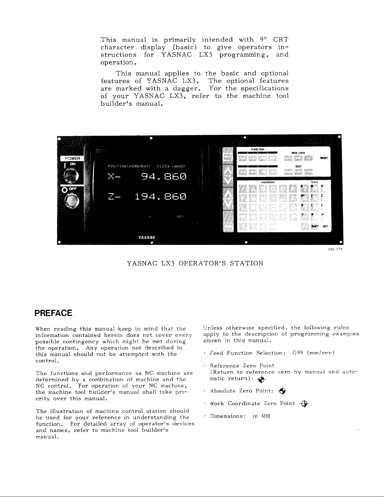
This manual is primarily intended with 9” CRT
character display (basic) to give operators in–
structions for YASNAC LX3 programming, and
operation.
This manual applies to the basic and optional
features of YASNAC LX3.
are marked with a dagger. For the specifications
of your YASNAC LX3,
builder’s manual.
The optional features
refer to the machine tool
YASNAC LX3 OPERATOR’S STATION
PREFACE
When reading this manual keep in mind that the
information contained herein does not cover every
possible contingency which might be met during
the operation. Any operation not described in
this manual should not be attempted with the
control,
The functions and performance as NC machine are
determined by a combination of machine and the
NC control.
the machine tool builder’s manual shall take prl–
ority over this manual.
The illustration of machine control station should
be used for your reference in understanding the
function. For detailed array of operator’s devices
and names, refer to machine tool builder’s
manual.
For operation of your NC machine,
586-175
TJnless otherwise specified,
apply to the description of
s“fiown in this manual.
Feed Function Selection:
Reference Zero Point
(Return to reference zero by manual and auto-
matic return) :
Absolute Zero Point:
Work Coordinate Zero Point
Dimensions: in MM
+
the following rules
programming examples
G99 (mm/rev)
+
+?
Page 3
TABLE OF CONTENTS
INTRODUCTION 1
1.
2.
PROGRAMMING 1
2.1
Tape Format 1
2.2
Program Number and
2.3
Coordinate Words 7
2.4
Rapid Traverse Rate
spindle-Speed Function (S-Function) 13
2.5
2.6
TOO I Function (T-Function) 14
2.7
Miscellaneous Functions (M-Function) 19
2,8
Preparatory Functions (G-Function) 23
3.
NC TAPE PUNCHING 148
3.1 Tape code 148
3.2 Programming 148
3.3 NC Tape 150
3.4 NC Tape Handling 150
4. STANDARD NC OPERATOR’S STATION WITH
CRT CHARACTER DISPLAY
Pushbuttons,
4.1
4.2
Power ON/OFF Operation 155
Display and Writing Operation 156
u. 3
4.4
Loading Part Programs and NC Data into
Memory (in) 174
Tape Verifying 178
4.5
Edit 180
4.6
4.7
Part Program and NC Data Output
Operations 183
4.8
Summary of Storing and Editing
Operations 186
Key S, and Lamps 151
sequence Number 6
10
151
5. MACHINE CONTROL
5.1 Switching Units on
5,2 Operation procedure 198
6.
OPERATION PROCEDURE 213
6.1
Inspection before Turning on Power 213
6.2
Turning on Power 213
6.3
Manual Operation 213
6.4
Preparation for Stored Lead Screw Error
Compensation and Stored Stroke Limit 214
6.5
Preparations for Automatic Operation 214
6.6
Operation in Tape and Memory Mode 215
6.7
Manual Operation Interrupting Automatic
Operation 216
6.8
Automatic Operation in MD I Mode 216
6.9
MD I Operation Interrupting Automatic
Operation 216
6.10 Preparation for Turning off Power 217
6.11 Turning off Power 217
APPENDIX 1
APPENDIX 2
APPENDIX 3
APPENDIX 4
APPENDIX 5
APPENDIX 6
LIST OF SETTING NUMBERS A–1
LIST OF PARAMETER NUMBERS A–?
STORED LEADSCREW ERROR COM-
PENSATION A–25
LIST OF STANDARD lNPUT/OUT-
PUT SIGNALS A–26
LIST OF ALARM CODES A–35
LIST OF DATA A–54
STATION 187
the Control Station
.
187
Page 4
INDEX
Subject
ABSOLUTE AND INCREMENTAL INPUT S............................ 2 ........ 2.3.5
A
ABSOLUTE/INCREMENTAL PROGRAMl,41NG (G90,
. . . . . . . . . . . . . . . . . . . . . .
G91)
Accelerationand Decelerationof Rapid Traverse
and Manual Feed .......................................$......2 ........ 2.4.3.
ADDING PART PROGRAMS
ADDRESS KEYS
...................................................
Address Search ....................................................4
ALARM CODE (ALM) DISPLAY
Alarm Code Display
Alarm Number of Microprograms ..................................2 ........
Argument Designation
AUTO MODE HANDLE OFFSET
.........................................
..................................... ........
................................................ ........
.............................................. ........
.....................................
AU TO MOD E HANDLE OFFSET SWITCHt ...................44......5
AUTOMATIC ACCELERATION AND DECELERATION ........0..0.....2 ........
AUTOMATIC COORDINATE SYSTEM SETTING+
..................... ........
AutomaticNose RFunction .........................................2
AU TOMATIC OPERATION INMDI h40DE ...........................6 ........
AUTOMATIC RETURN TO REFERENCE POINT (G28)
AutomaticThreading Cycle (G76)...................................2
AutomaticWritingintothe Tool CoordinateMemory
................ ........
................. ........
Chapter
2
4
“.””””..4.6.4
4
.’””””””4.1.4
........
4
4
2
........
5
........
5
........
2
........
5
AutomaticWritingintothe Work CoordinateSystem
ShiftLIemory..................................................5 ........
BUFFER REGISTER
B
................................................ ........
2
BUFFERING FUN CTION(M93, M92)t ..............................-2 ........
C CANNED CYCLES (G90, G92, G94) ................................ 2 ........
CHECKING REGISTERED PART PROGRAM NUMBER ................. 4
........
CircularArc MultipleCornering (G112) .............................2 ........
CIRCULAR INTERPOLATION (G02, G03)
........................... ........
2
CIRCULAR PATH hfODE ON/OFF ON TOOL RADIUS COMPENSATION
(G97, L496)+
................................................. ........
2
COMMAND DATA DISPLAY ..........................................4 ........
Command Data Display .............................................4
........
Command Pulse AccumulationRegisterDisplay
(COMMAND PULSE) ........................................... 4 ........
Conditionsforthe AutomaticNose R CompensationFunction
to be Enabled ................................................ 2 ........
Conditionsof the Specificationsto Perform FS Editing.............. 5 ........
Considerationsand Remarks for Macro Programs ................... 2 ........
CONSTANT DISPLAY .............................................. 4 ........
CONSTANT SURFACE SPEED CONTROL (G96, G97)t ............... 2 ........
ControlComma~ ds
................................................. ........
2
CoordinateSystem Setting (G50 X_. Z_. ) ........................ 5 ........
COORDINATE WORD S.............................................. 2 ........
COORDINATE WORDS .............................................. 2 ........
CORNERING (Gil, G12)+............ 2
............................... ........
CRT CHARACTER DISPLAY ........................................ 4 .......
CURRENT POSITION DISPLAY ..................................... 4 ........
CURSOR KEYS
CUTTING DEPTH OVERRIDE SWITCHt FOR G71 AND G72
CYCLE START PUSHBUTTON AND LAMP
DATA KEYS .......................................................4 ........
D
DECIMAL POINT PROGRAMMING
DELETING PART PROGRAM BLOCKS
Display and Deletingof RegisteredProgram Number
(PROGRAM NO. TABLEDR )t
Displayand Writeof Localand Common Variables
DISPLAY AND WRITING OPERATION
Displayof Subprogram Run Status (SUB PROG . NESTING)
Displayof Tool LifeControl Use Status (TOOL LIFE CONTROL) .... 4
Displayin EDIT Mode .............................................. 4
DISPLAYING AND CHECKING STORED PART PROGRAMS ...........
.................................................... ........
.......... ........
.................
......... ........
...................................
............................... ........
.................................
..................
...............................
.........
4
5
5
........
2
4
.,.,....
4
........
2
........
4
........
4
........
........
........
4
Par.
Page
. .. .
2.8.31
4.3.3.4““”
4.3.9 -.O..
4.3.9.1-..
2.8.23.10-
2.8.23.2‘.
5.2.7 ‘----
5.1<28 ----
2.4.3
5.2.2
2.8.19.1..
6.8
2.8.11 ....
2.8.25.8‘.
5.2.3.3 .“”
5.2.3.4 .“’
2.1.5 ..”””
2.7.3 .“”””619
2.8.26 ‘“””
4.6.1
2,8.30.2..
2.8.4 .....
2.7.4 .....
4.3.2 .....
4.3.2.1 ...
4.3.4.9.. 165
2,8.19.2..
5.1.31.7..
2.8.23.9“.
4.3.1 .....
2.8.27..-.
2.8.23,6-.
5.2.3,5...
2.3
2.3.1
2.8.7
4,1.2 ....-
4,3.4
4.1.8
5.1.29 ....
5.1.2 ....
4.1.5....
2.1.3 ...,.
4.6.5
4.3.9.3 ...
2,8.23.8,.
4.3
4.3.2.2 ...
4.3.2.3 ...
4.3,3.3 ...
4.6.2
..”” 146
. . .
.,. .
. . . .
.....
.....
.......
.....
.......
.....
.....
.....
.....
.....
.......
.....
12
181
153
161
172
172
88
68
212
195
12
199
56
216
35
109
203
204
116
180
143
28
20
157
158
56
198
84
156
123
81
205
31
152
162
154
195
188
153
182
173
83
156
158
159
161
180
8
7
7
6
Page 5
INDEX (Conttd)
Subject
DISPLAYING AND WRITING PARAMETERS .......................... 4 ........ 4.3.7 ..... 17o
D
Displayingand WritingParameters
DISPLAYING AND WRITING SETTING DATA (SETTING) ............ 4 ........ 4,3.6 ..... 168
DISPLAYING AND WRITING TOOL OFFSET DATAt
DISPLAYING STATUS INPUT/OUTPUT SIGNALS
Displayin Memory Run Mode (PROGRAM
DISPLAY LOCK/MACHINE LOCK SWITCH
DRY RUN SWITCH
......................
DWELL (G04).o.....................o....
E EDIT
...................................
EDIT KEYS
EDIT LOCK SWITCH
.............................
............................................... ........
EIA/ISO AUTO RECOGNITION ...................................... 3 ........ 3.1,2 ..... 148
EMERGENCY STOP PUSHBUTTON
ERROR DETECT OFF POSITIONING (G06) .............4............ 2 ........ 2.8.2.2 ... 27
Example of FS Editing
............................................. ........
Example of High-speed M Function Processing
Exercisesof Macro Programs
Facing Cycle B (G94)
F
..............................................
FEED FUNCTION (F- AND E-FUNCTION)
FEED HOLD PUSHBUTTON AND LAMP
FEED/MINUTE AND FEED/REVOLUTION SWITCHOVER .............. 2 ........ 2,8.28 .... 124
Feed Per Minute (G98 Mode)
Feed Per Revolution(G99 Mode)
FEEDRATE OVERRIDE CANCEL SWITCH
FinishingCycle (G70)
FS AUTOMATIC EDITING FUNCTION
FUNCTION KEYS
Functions
Functions
G General
General
General
General
......................................................... 2
.........................................................
...........................................................
........................................................... ........
...........................................................
...........................................................
GENERAL PROGRAM FORM
G50 POINT RETURN SWITCHt
G50 POINT RETURNt
.............................................
..................................................
......................................... ........
..............................................
.................................
.................
...................
MEM]) ................... 4 ........ 4.3.3.2 ... 160
..........................
..........................
.......................... ........
.......................... ........
..........................
..................................
......................
...................................... ........
.......................... ........
.............................
....................................... ........
...................................
...........................
...............................
.....................................
Chapter
4
........ 4,3.7.3 ... 171
4
........ 4.3.5 ..... 166
4 ........ 4.3.8 ..... 172
5
........ 5.1.19 .... 193
5 ........ 5.1.18 .... 193
2
4
4
........ 4.1.10 .... 154
5
5 ........ 5.1.4 ..... 189
5
2
........ 2.7.8.4 ... 23
2
2
........ 2.8.26,3 .. 121
2
5 ........ 5.1.3 ..... 188
2 2.4.2.2 ... 12
2
........ 2.4.2.1 ... 11
5 ........ 5.1.12
2
........ 2.8.25.5... 106
5 ........ 5.1.31..... 196
4
........ 4.1.3 ..... 152
........ 2.6.5.2 ... 17
5 ........ 5.1.31.3... 196
2
........ 2,8.25.1... 94
5 5.1.8.2
5 ........ 5,1.31.1... 196
5 ........ 5.2.3.10... 206
3
5
........ 5.1.24 .... 195
5 ‘-------5.2.4 ..... 208
Par.
2.8.5 ..... 29
4.6
........ 180
5.1,22
5.1.31.6 .. 197
2.8.23.11.. 89
2.4.2
3.2.2
...... 148
GROOVE WIDTH COMPENSATION (G150, G151)*..................... 2 ........ 2.8,32
Grooving in X-Axis (G75) .......................................... 2 ........ 2.8.25.7... 108
Page
.... 194
.....
... 192
... 190
.... 147
10
HANDLE AXIS SELECT SWITCH+ ................................s.. 5 ........ 5.1.6...... 189
H
HANDLE DIAL+ (MANUAL PULSE GENERATOR)
HANDLE DIALS FOR SIMULTANEOUS CONTROL OF
UP TO TWO AXESt
Handle InterpolationFunction
HIGH-SPEED M FUNCTION
..........................................
......................................
........................................ ........
I Improved MultipleRepetitiveCycle Function ........................ 2 ........ 2.8.25.10.. 115
INCH/METRIC DESIGNATION BY G CODE (G20, G21)t
....<...............
............. ........
5 ‘-------5.1.5 ----- 189
5
..-.-... 5.1.8 ..4-. 189
5
.....+.. 5,1,8.1---- 190
2
2
2.7.8
2.8.8
.....
......
22
33
Input/Output ...................................................... 5 ........ 5.1.31.2... 196
I/OChannel ...................................................... 2 ........ 2.7.8.1 ... 22
INPUTTING SETTING DATA AND PARAMETER DATA
INPUTTING TOOL OF OFFSET DATA INTO MEMORY
Input Unit andl O Times Input Unit ............................... 2 ........ 2.3.3.1.... 7
INSPECTION BEFORE TURNING ON POWER
INTERLOCK INPUT (INTERLOCK)
InternalToggle Switchesf
INTRODUCTION
JOG FEEDRATE SWITCH AND FEEDRATE OVERRIDE SWITCH
J
...................................................
.........................................
.................................
........................
JOG PUSHBUTTONS AND RAPID PUSHBUTTON
K KEEPING OF NC TAPE
............................................
.............. ........
...............
.......
....................
4
4
........ 4.4.4 ..... 177
4.4.5
..... 178
6 ........ 6,1 ....... 213
5 ........ 5.1.23 .... 195
4 ........ 4.3.6.2 ... 169
.....................
1
5
........ 5,1.10 ..... 191
5
........ 5.1.9 ..... 191
........ 3.4.2 ..... 150
3
1
Page 6
INDEX (Cent’cl)
Subject
LABEL SKIP FUNCTION
L
LEAST INPUT INCREMENT AND LEAST OUTPUT INCREMENT ...... 2 ........ 2.3.3 ..... 7
Least Output Increment
LINEAR INTERPOLATION (GOl)t ................................... 2 ........ 2.8.3 ..... 2;
LIST OF ADDRESS CHARACTERS AND FUNCTION CHARACTERS .. 2 ........ 2.1.2 ..... 4
LIST OF ALARM CODE ..............................
LIST OF DATA ...............................................APPENDIx 6 ................A-54
LIST OF G CODES
LIST OF PARAMETER NUMBERS
LIST OF SETTING NUMBERS ............
LIST OF STANDARD INPUT/OUTPUT SIGNALS .........-......APPENDIX 4 ................A-?.&
LIST OF TAPE CODE
LOADING PART PROGRAM TAPE INTO MEMORY ............
LOADING PART PROGRAMS AND NC DATA INTO MEMORY (
LOADING PART PROGRAM SBYMDI .......................
M MACHINE CONTROL STATION
Macro Program CallCommands
MAC REPROGRAMS (G65ANDG67) ................................ 2 ........ 2.8.23 .... 66
MaintenanceHistoryDisplay (MAINTENANCE) .......................4 ........ 4.3.9.5.... 174
MAKING ADDITION TO A PART PROGRALf
MANUAL ABSOLUTE SWITCH ...................................... 5 ........ 5.1.21..... 194
MANUAL INTERRUPTION POINT RETURN Sh’ITCH ................. 5 ........ 5.1.25..... 195
MAN UAL INTERRUPTION POINT RETURN* ......................... 5 ........ 5.2.5 ..... 209
MANUAL OPERATION *...... ....................................... 6 ........ 6.3 ....... 213
MANUAL OPERATION INTERRUPTING AU TOhfATIC OPERATION .... 6 ........ 6.7
MANUAL PULSE hlULTIPLY SELECT SWITCH+
hfANUAL REFERENCE POINT RETURN SWITCH . .................... 5 ........ 5.1.14 .... 192
MANUAL RETURN TO REFERENCE POINT .......................... 5 ........ 5.2.1 ..... 198
L4AXIMUM PROGRAMhfABLE DIMENSIONS ........................... 2 ........ 2.3.4 ...-.
MAXIMUM SPINDLE-SPEED SETTING (G50)+ ...........4............ 2 ........ 2.8.21 .-.. 6!
........................................... ........
........................................... ........
.........AppENDIX 5................A-35
................................................ ........
..............................
......................APPENDIX 1 ................ A-1
......................................
.............................
..................................... ........
......................... ........
......................
Chapter
2
2
2
APPEND IX . ............... A-7
2
4
5 ........ 5.1.7 .....
Par.
2.1.4 ..... 6
2.3.3.2 ...
2.8.1 ..... 23
2.8.23.1 .. 66
4.4.2 ..... 176
.......
Page
216
189
M CODES FOR INTERNAL PROCESSING (G99 TO M109) ............. 2 ........ 2.7.2 ----- 19
MCODES FOR STOP (MOO, MO1, M02, M30) ........................ 2 ........ 2.7.1
k4DIOPERATION INTERRUPTING AU TOhiATIC OPERATION ......... 6 ........ 6.9
MEASURED WORKPIECE VALUE DIRECT INPUT + .................... 5 ........ 5.2.3 ..... 199
MEMDATA (MEMORY DATA) KEYS ................................ 4 ........ 4.1.11....- 154
Message Display (ALARM)t
M-FIJNCTION LOCK SWITCH (AUXILIARY FUNCTION LOCK)
MISCELLANEOUS FUNCTIONS (M-FUNCTION) ...................... 2 ........ 2.7 ....... 19
MODE SELECT SWITCH
MODIFYING PART PROGRAM BLOCKS ............................. 4 ........ 4.6.3 ..... 180
M3-DIGIT BCD OUTPCTt
Multi-blockWritingand Operationin MDI Mode ..................... 4 ........ 4,3.3.1 ... 159
MULTIPLE CORNERING (Gill, G112)+ ............................. 2
MULTIPLE REPETITI\’E CYCLES (G70 TO G76)t 2
MULTI-START THREAD CUTTING (G32)t .......................... 2 ........ 2.8.16..... 41
N NC TAPE .......................................................... 3 ........ 3.3........ 150
NC TAPE CHECK .................................................. 3 ........ 3.3.3 ..... 150
NC TAPE HANDLING
NC TAPE PUNCH
NC TAPE PUNCHING .............................................. 3 ..................... 148
NEW COORDINATE SYSTEM SETTING FUNCTION ................... 2 ........ 2.6.5 ..... 17
NEXT KEY
New Tool SetterFunction .......................................... 5 ........ 5.2.3.9 ... 206
No. of Servo Lag Pulses Display (ERROR PULSE) 4
Notes
NOTES WHEN USING THE CONVENTIONAL G50T****FUNCTION .... 2 ........ 2.6.6 ..... 19
OffsetCalculationof AutomaticNose R Compensation Approach
0
and Relief.................................................... 2 ........ 2.8.19.3 .. 57
OffsetScreen Display ............................................. 5 ........ 5.2.3.8.... 205
Operation.......................................................... 5 ........ 5.1,8.3 ... 190
OperationCommands ............................................... 2 ........ 2.8.23.5 .. 79
OperationExpressionfor CoordinateSystem Setting
........................................................ ........
............................................................. ........
................................................. ........
........................................
.......
............................................ ........
.......................................... ........
................... ........
..............................................
................. ........
................ ........
4
........ 4.3.9.2 ... 172
5 .......,5.1.20..... 194
5
2 2.7.7 ..... 21
........
3 ........ 3.4 .......
3 3.3.2 ..... 150
4 4.1.6
2
2
5.1.1 ..... 187
2.8.30..... 134
2.8.25..... 94
4.3.4.8 ... 165
2.7.8.3 ... 23
2.6.5.3 ... 18
.....
.......
..... 153
19
216
150
Iv
Page 7
INDEX (Cent’d)
Subject
OPERATION IN TAPE AND MEMORY MODE 6
o
OperationProcedure
OPERATION PROCEDURE
OPERATION PROCEDURE
...............................................
..........................................
.......................................... .....................
......................... ........
Chapter
5 ........ 5.1.31.4 .. 196
5 ........ 5.2 ....... 198
6
Par.
6.6 ....... 215
OperationTime Display ............................................ 4 ........ 4.3.9.4 ... 174
OPTIONAL
OPTIONAL BLOCK SKIP SWITCH
ORG (ORIGIN) KEYS
OTHER M CODES
BLOCK SKIP (/1-/9)+
..............................................
..................................................
OUTPUTTING PART PROGRAM TO PAPER TAPE
OUTPUTTING SETTING IPARAMETER DATA TO PAPER TAPE
OUTPUTTING TOOL OFFSETS TO PAPER TAPE
Overview
.........................................................
. . . . . . . . . . . . . . . . . . . . . . . . . . . . . . . . . .
..................................
...................
....................
......
2 ........ 2.2.3
5 ........ 5.1.17 .... 193
........
4
4.1.9 ..... 154
2 ........ 2.7.6
4 ........ 4.7.1 ..... 183
4 ........ 4.7.3 ..... 184
4 ........ 4.7.2 ..... 184
2 ........ 2.6.5.1 ... 17
Overview of L4acroProgram Body .................................. 2 ........ 2.8.23.3 .. 69
PAGE KEYS
P
PAPER TAPE
Parameter of Bit DisplayFormat
Parameter of DecimalDisplay Format 4
Parameters
Parameters ........................................................ 5 .......- 5.2.3.2 ‘o- 203
PART PROGRAM AND NC DATA OUTPUT OPERATIONS
PatternRepeating (G73)
.......................................................
..................................................~..
............................
.......
............................... ........
.................
.......................................
...........4........
..........................................
4 ........ 4.1.7 ...... 153
3 ........ 3,3.1 ..... 150
4 ........ 4.3.7.1 ... 171
4.3.7.2
2
........ 2.7.8.2 ... 22
........
2
4.7 ....... 183
2.8.25.4 .. 104
Peck Drillingin Z-axis (G74) ...................................... 2 ........ 2.8.25.6 .. 107
Position........................................................... 4 ........ 4.3.4,4 ..- 163
Position[ABSOLUTE]
Position
Position(EXTERNAL) “O” Setting.................................. 5 ........
[EXTERNAL I . . . . . . . . . . . . . . . . . . . . . .. . . . . . . . . . . . . . . . . . . . . . . . 4 ........ 4.3.4.1 ... 162
Position[INCREMENT]
POSITION (GOO, G06)
..............................................
.............................................4........ 4.3.4,3 ... 163
............................................. ........
........ 4.3.4.2 ... 163
4
5,2.3.6 ... 205
2 2.8.2
.....
.....
... 171
.....
Page
213
7
21
24
Positioning(GOO)
POSITION STORED PUSHBUTTON+ 5
POWER ON/OFF OPERATION
..................................................
..............................
................................ ........
......... ........
POWER ON IOFF PUSHBUTTONS ................................... 4
2 ........ 2.8.2.1 ... 24
5.1.30..... 196
4
........
4.2 ....... 155
4.1.1
Precautionsin Programming G70 through G76 ...................... 2 ........ 2.8.25.9... 112
PREPARATION FOR STORED LEADSCREW ERROR COMPENSATION
AND STORED STROKE LIMITt
PREPARATION FOR TURNING OFF POWER .......................6 ........ 6.10 .“...- 217
PREPARATIONS FOR AUTOMATIC OPERATION
...............................
..................... ........
6 ........ 6.4 ....... 214
6
6.5 ......-. 214
PREPARATORY FUNCTIONS (G-FUNCTION) ........................ 2 .......” 2.8 -------- 23
PROCESS SHEET ...........................”....,.......-.””-”-””3 ““-””--” 3.2.1”””-”- 148
PRoGRAMh41NG
PROGRAMMING
PROGRAhIMING OF ABSOLUTE ZERO POINT (G50)
PROGRAM MIRROR IhiAGE (G68, G69)t
PROGRAM NUMBER
PROGRAM NUMBER AND SEQUENCE NUMBER
PROGRAM RESTART SWITCHt ..................................... 5
PROGRAM RESTARTt .......-..........~.......................... 5 ....---- 5.2.6 ““”-- 209
Program Return
PUSHBUTTONS, KEYS, AND LAMPS
RADIUS PROGRAMMING FOR CIRCULAR INTERPOLATION
R
(G22, G23)t .................................""-""""----"""-""2 ““””””””2.8.9 ”-””-- 33
RAPID TRAVERSE RATE
RAPID TRAVERSE RATE.... ....................................... 2 ...~....2.4.1
RAPID TRAVERSE RATE OVERRIDE SWITCH
REFERENCE POINT CHECK (G27)
REFERENCE POINT LAMPS
.................................................... .....................
....................................................
.................
............................
................................................
......................
................................................... ........
...............................
...........................................
.......................
..................................
..............................
..........
2
3 ........ 3.2 ‘.....- 148
........
2
........
2
........
2
........
2
........
4 4.3.4.5
...$.... 4,1
4
2 .....s.. 2.4
2.8.20
2.8.24 .... 92
2.2,1
.......
2.2
5.1.26 .... 195
.......
.......
5 ........ 5.1.11 .... 192
2 ........ 2.8.10 -... 34
5 ........ 5,1.15 .... 193
Registrationof Macro Programs .................................... 2 ........ 2.8.23.7... 83
RESET KEY ..........................................-.....O------4 .-o-----4.1.12 ..-.. 155
RETURN FROM REFERENCE pOINT (G29)
..........................
2 ........ 2.8.12
..... 152
.-”-4 61
.....
... 164
151
.....
.....
10
10
36
1
6
6
v
Page 8
INDEX (Cent’d)
Subject Chapter
2ND REFERENCE POINT RETURN (G30)t .....0....4................ 2 ........ 2.8.13...... 37
s
SEQUENCE NUMBER
SettingData of Bit DisplayFormat
SettingData of DecimalDisplayFormat
S4-DIGIT PROGRAMMING At
S4-DIGIT PROGRAMMING B+
SIMULTANEOUS CONTROLLABLE AXES
SINGLE BLOCK SWITCH
SKIP FUNCTION (G31)t
...............................................
................................. ........
............................
....................................... ........
....................................... ........
............................
...........................................
...........................................
2
........ 2.2.2
4
4
........ 4.3.6.3 ... 169
2
2
2
........ 2.3.2
5
........ 5,1,16 .... 193
2 ........ 2.8.14 .... 37
Par. Page
4.3.6.1
2.5,2
2.5,3
SUBROUTINE PROGRAM (M98, M99) ...............o................ 2 ........ 2.7.5
SpindleCounter
SPINDLE SPEED OVERRIDE SWITCHt
SPINDLE-SPEED FUNCTION (S-FUNCTION)
SPLICING NC TAPES
S2-DIGIT PROGRAMMING (SPECIAL SPECIFICATIONS)
STANDARD NC OPERATOR’S STATION WITH
CRT CHARACTER DISPLAY
Stock Removal in Facing (G72)
Stock Removal in Turning (G71)
STORED LEAD SCREIi ERROR COMPENSATION
STORED STROKE LIMIT (G36-G39)
SWITCHING UNITS ON THE CONTROL STATION
T TAPE FORMAT .............................................. ....... 2 ........ 2.1
................................................... ........
..............................
........................
...............................................
.............
.................................. .....................
....................................
...................................
.................
................................ ........
...................
4
4.3.4.7.... 165
5 ........ 5.1,13 .... 192
2 ........ 2.5 ........ 13
3 ........ 3.4.1 ..... 150
2 ........ 2.5.1
4
2 ........ 2.8.25.3... 101
2 ........ 2.8.25.2... 95
APPENDIX 3
2
................A-25
2.8.18..... 44
5 ........ 5,1 ....... 187
.......
TAPE FORMAT ..................................................... 2 ........ 2.1.1
The G40 GO1 X_ Z—I— K—;
Also Availablein the AutomaticNose R Function .............. 2 ........ 2.8.19.4... 61
TOOL FUNCTION (T-FUNCTION)
T 4-DIGIT PROGRAMMING
TOOL OFFSET MEMORY t........................................... 2 ........ 2.6.2 14
TOOL POSITION OFFSETS
Command Cancel Function is
..................................
.........................................
......................................... ........
2 ........ 2.6
2 ........ 2.6.1
2
........
......
2.6,3
.....
... 168
.....
.....
.....
.....
.....
.....
.....
.....
7
13
14
7
20
13
151
1
1
14
14
15
W WORK COORDINATE SYSTEM SHIFTt .............................. 2 ........ 2,6.4 ..... 17
x X-AXIS DIAMETER /RADIUS SWITCHING ............................ 2 ........ 2.3.6 ..... 10
Page 9
1. INTRODUCTION
YASNAC LX3,
is a combination of two high-performance 16-bit
microprocessors running in parallel.
ing our modern system technique, it is designed
to provide the highest lathe performance.
The dual processor CNC system drastically reduces the data processing time to meet highspeed cutting.
creased by the use of high-speed buffer function and buffering function.
. Enhanced cutting capability includes a maximum
of 24 meters /rein feed command, precise feed E
command, 500-milimeter lead thread cutting,
continuous thread cutting, multiple thread
cutting, and variable pitch thread cutting.
To meet FMS trends, program interrupt function, tool life control, user macro, tool set
error correction, stored stroke limit per tool,
and other functions can be installed.
IIultraspeed dual processor CNC”
Incorporat-
Block-to-block stop time de-
2. PROGRAMMING
. Part program memory can be extended to a
maximum of 320 meters .
interface is available with FACIT, RS232C and,
in addition, RS422 serial interface capable of
high-speed long distance transmission.
. Programming is further facilitated by improved
tool radius compensation function, G 50–work
coordinate system setting, angle–specified line–
ar interpolation, and combined beveling/rounding function.
. The servo function uses a drastically miniatur-
ized and low-noise, newly transistorized PWM
control unit and a high-performance DC servo
motor.
The position feedback is available with the
standard pulse generator (PG) system and,
the inductosyn-applied complete closed loop
system.
Its data input loutput
2.1 TAPE FORMAT
2. 1.1 TAPE FORMAT
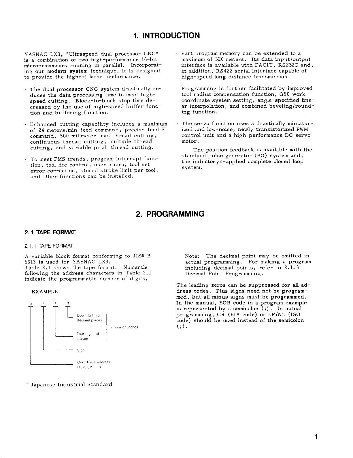
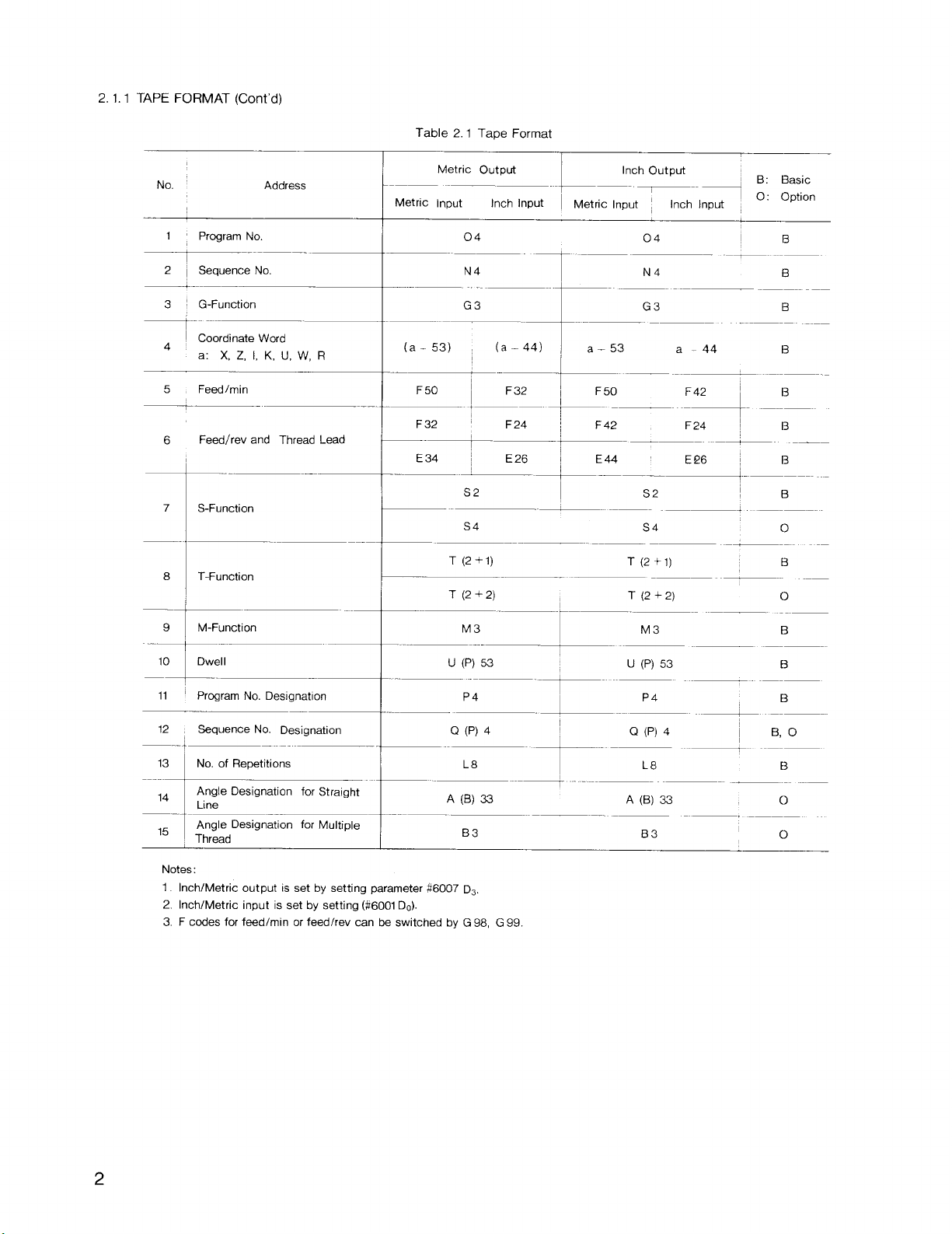
A variable block format conforming to JIS# B
6313 is used for YASNAC LX3.
Table 2.1 shows the tape format.
following the address characters in Table 2.1
indicate the programmable number of digits.
EXAMPLE
+
a
1-
~ .Oodnaeadd=s
# Japanese Industrial Standard
4
3
—
Down to thtro
L
dec]mal places
L
Four d[glts of
Integer
Sign
(X, ZI, K )
Numerals
,n mm or inches
Note: The decimal point may be omitted in
actual programming.
including decimal points, refer to 2. 1.3
Decimal Point Programming.
The leading zeros can be suppressed for all address codes. Plus signs need not be programmed, but all minus signs must be programmed.
In the manual, EOB code in a program example
is represented by a semicolon (;) . In actual
programming, CR (EIA code) or LF /NL (1S0
code ) should be used instead of the semicolon
(;).
For making a program
Page 10
2, 1.1 TAPE FORMAT (Cent’d)
Table 2.1 Tape Format
No.
1
Prcgram No
.-
2
Sequence No.
I
G-Function
Coordinate Wmd
4
a: X, Z, 1, K, U, W, R
5
Feed/rein
Feed/rev and Thread Lead
6
.
7
S-Function
8
T-Function
M-Function
9
10
Dwel I
11
Program No. Designation
——
.—
12
Sequence No. Designation
13
No. of Repetitions
Angle Designation for Straight
14
~
Line
Angle Designation for Multiple
15
~
Thread
Address
Metric output
Metric Input
Inch Input
.—
04
—- - -_
N4
G3
(a- 53)
F 50
F32
—-~
E34 ! E26 ~ E44
I
+——
.=-
(a-44)
~~ ‘— -“;42 ‘“-—---
F24 *- -
S2
-. –——– .—
54
T(2+I) T(2+I)
T(2 +2) T(2 +2)
M3
-–-~-
-. .-
U(P) 53
Q (P) 4
A (B) 33 A (B) 33
P4
L8
_+_ ‘(P)53 . :
L.... ‘4 ; __
4--- Q “) 4 ‘ ---~
...+ .––—— —— .—
—— —..
B3
~–-
Metric Input ~
I
~ a_53
F 42
\
-~-——–
I
-.
r
I
Inch Output
——–
‘
Inch Input i
04
-7— ---
N4
G3 B
a-44 B
.+- .___B_
F24
—— ———
E!26 ~ B
S2 B
—+
S4
————
.—
M3
L8
—— ..—
—,
B3
B: Basic
O: Option
~
. .
B
B
B
0
B
0
B
B
0
o
Notes:
1. Inch/Metric output is set by setting parameter *6007 D3,
2. Inch/Metric input is set by setting (#?6001Do).
3. F codes for feed/rein or feed/rev can be switched by G 98, G 99
2
Page 11
Program No. O
Address
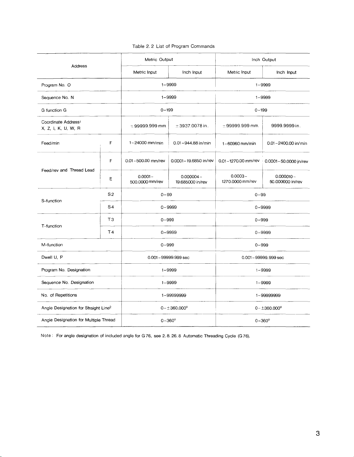
Table 2.2 List of Program Commands
Metric Output Inch Output
—-——-—
Metric Input
Inch Input
I
Metric Input Inch Input
1-9999 1-9999
Sequence No. N
G function G
Coordinate Addressl
X, Z, 1, K, U, W, R
Feedfmin
Feed/rev and Thread Lead
S-f unction
T-function
M-function
Dwell U, P
I
i
L
S4
T3
T4
F
F
E
S2
* 99999.999 mm
1– 24000 mmlmi n
0.01-500.00 mmlrev
0.0001-
500,0CK)0 mmlrev
0.001 – 99999.999 sec
1-9999
0-199
? 3937.0078 in
1
~ 0.01 –944.88 in/rein
0.0001-19.6850 in/rev
o,CKD304-
19,685030 in/rev
o-99
0-9999
o-999
o-9999
o-999
1– 9999
0-199
I
~:=
0.01 –1270.00 mm/rev 0.0001 –50.00CQ inlrev
ooo~ o,oooolo_
1270.0000 mmlrev
——
I
I
I
0.001 –99999.999 sac
50 .00Ci)OO inhev
o-99
0-9999
o-999
o-9999
0-999
Program No. Designation
Sequence No. Designation
No. of Repetitions
Angle Designation for Straight Lin#
—
Angle Designation for Multiple Thread
Note : For angle designation of included angle for G 76, see 2.8.26.8 Automatic Threading Cycle (G 76).
—
1-9999 1–9999
1–9999
1-99999999 1– 99999999
O– ? 360.~0°
0-360”
I
I
1– 9999
0- t360.000°
0–360”
3
Page 12
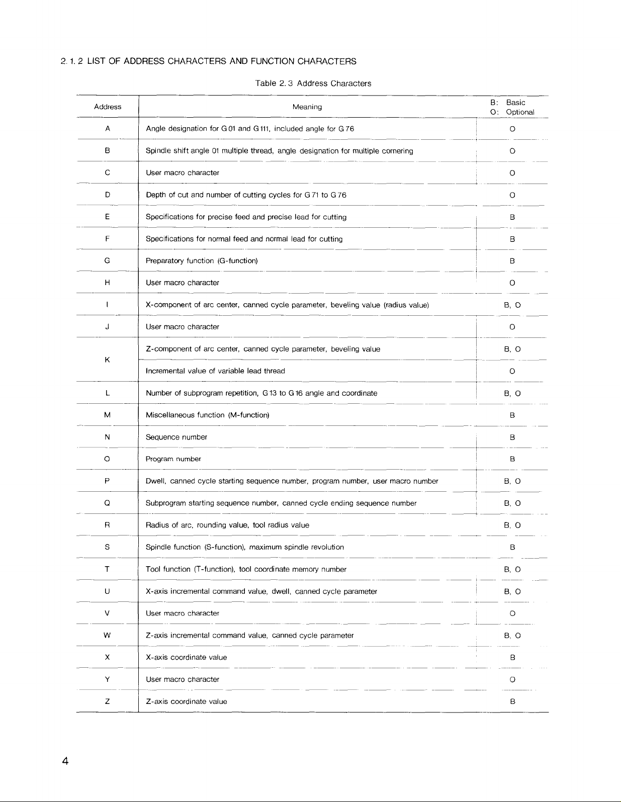
2.1.2 LIST OF ADDRESS CHARACTERS AND FUNCTION CHARACTERS
Table 2.3 Address Characters
Address Meaning
A
B Spindle shift angle Ol multiple thread, angle designation for multiple cornering o
c
Angle designation for GOl and Gill, includfxf angle for G76
-.
User macro character
—– .——
.— ——
——— ———
D
E
F
G
H User macro chaacter o
I X-component of arc center, canned cycle parameter, beveling value (radius value) B, O
J
K
Depth of cut and number of cutting cycles for G 71 to G 76
Specifications for precise feed and precise lead for cutting
—— ~. ‘— -
Specifications for normal feed and normal lead for cutting
Preparatmy function (G-function) B
—
User macro character
Z-component of arc center, canned cycle p~ameter, beveling value
.-
Incremental value of variable lead thread
.—.
+- —– —
I._ .—
.——
——— .—— —
I
~
–—— + —–——
–— —— —–—
L
M
Number of subprogram repetition, G 13 to G 16 angle and coordinate
.—.
Miscellaneous function (M-function)
— .— .—
B: Basic
O: Optional
o
o
0
B
o
B, O
o
B, O
B
N
o
P
Q
—
F?
s
T
u
v
Sequence number B
— .—
Program number
Dwell, canned cycle starting sequence number, program number, user macro number B, O
-—
Subprogram starting sequence number, canned cycle ending sequence number B, O
Radius of arc, rounding value, tool radius value
Spindle function (S-function), maximum spindle revolution B
Tool function (T-function), tool coordinate memory number B, O
. —.
X-axis incremental command value, dwell, canned cycle parameter B, O
User macro character
- ~ —— —
-—— —–—
—— -—
I
—t—
\
I
—. .— .—
.—
B
B, O
o
–—— .——
w
Z-axis incremental command value, canned cycle parameter B, o
——
x
Y
z
X-axis coordinate value B
User macro character
Z-axis coordinate value
o
B
Page 13
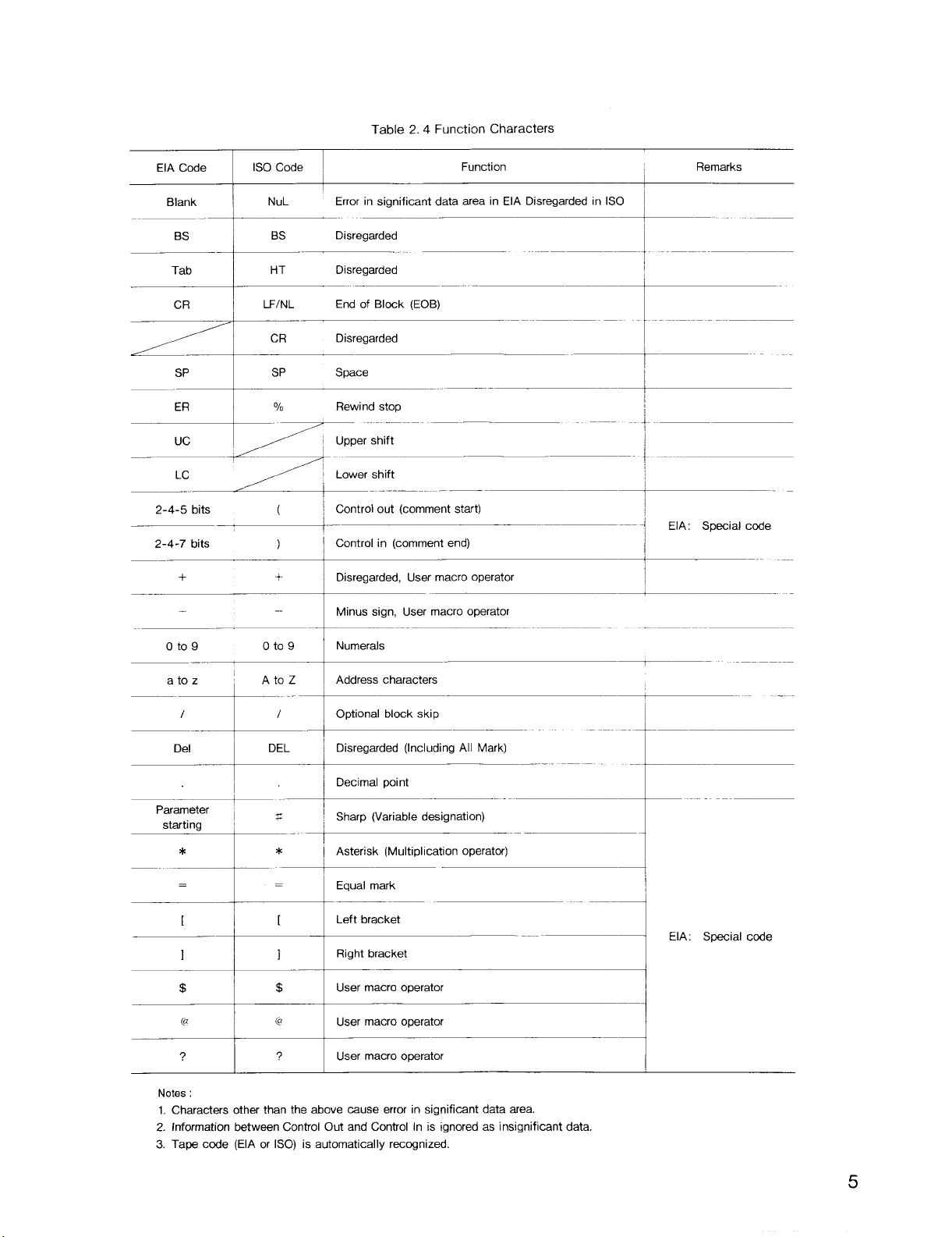
Table 2.4 Function Characters
Function Remarks
——~—
-~ ‘-
—
—-––~-
‘-
1-------._
—+
—
>
EIA Code
Blank
BS
Tab
SP
ISO Code
I
NuL
0S
e--
HT Disregarded
LFINL
c!+ Disregarded
SP Space
Error in significant data area in EIA Disregarded in ISO i
Disregarded
.—
End of Block (EOB)
--+>5::::----‘-- ----/– -
2Z2::F.. . .. .1. - ._:-=..
2-4-5bits
~“—
2-4-7 bits
..~
‘--;~~*“” --------------‘-
oto9 Oto 9 I Numerals
~ Control out (comment start)
(
~ Control in (comment end)
)
Disregarded, User macro operator
Minus sign, User macro operator
I
-!
EIA: Special code
]
1
‘ Ad=== ‘-–-
—~tx—-----~ ‘-
:-ti~––-- ‘--- ---4
1 Disregarded (Including All Mark)
‘:+* -------!----
—.~ --
Parameter ~
starting ~
*
s
I
*
I
‘ -Ld=:k-- ‘ ------4
: -H- -1“A:‘“iacde
?
Notes :
1. Characters other than the above cause error in significant data area.
2. Information between Control Out and Control In is ignored as insignificant data.
3. Tape code (EIA or ISO) is automatically recognized.
17 I
I
i Sharp (Variable designation)
!
[ Asterisk (Multiplication operatcx)
User macro operator
I
-.
5
Page 14
2.1.3 DECIMAL POINT PROGRAMMING
Numerals containing a decimal point may be used
as the dimensional data of addresses related to
coordinates (distance) , angle, time and speed.
They can be input” from punched tape or MDI.
Decimal points can be used in the following ad-
dress words.
Coodinate words;
Angle words: A, B
Feedrate word: F, E
Time words: U, P
EXAMPLE
X15.
z20.5—
(G99)F.2t —FO.20 mm/rev or
X, Z, U, W, I, K, R
[mm]
X15.000 mm or
220.500 mm or
(for F32)
[inch ]
X15.0000 in.
220.5000 in.
FO. 2000 infrev
(for F24)
The blocks including the following
are not read in advance .
. MOO, MO1, M02, M30
. M codes ( 6 maximum) set by parameter com-
manding to stop advance–reading.
Notes :
M codes
1. This function is effective for G22 and G 23
where the control is provided with Radius
Programming for Circular Interpolation option.
2.
Block-to-block stop time due to the time
required to compute tool radius compensation is not eliminated or remains.
this stopping time, use 2.7.3
Function (M93, M92) (optional).
tion of consecutive blocks up to 5 in M93
mode, inter-block stoppage time is reduced
to zero.
To reduce
Buffering
When opera-
2.2 PROGRAM NUMBER AND SEQUENCE
NUMBER
(G98)F25.6 F25 mm/min or
G04Pl.—
When data without a decimal point is input, the
control regards
LABEL SKIP FUNCTION
2.1.4
In the following cases the label skip function
becomes effective, and LSK is displayed on the
CRT .
. When the power supply is turned on.
. When the RESET operation is executed.
While the label skip function is effective, all data
on the punched tape up to the first EOB code are
neglected.
the MEM (memory) or EDIT (editing) mode, it indicates the presence of a pointer at the leading
end of the part program.
BUFFER REGISTER
2. 1.5
During normal operation, one block of data is
read in advance and compensation is computed
for the follow-on operation.
In the tool radius compensation”- mode, two
blocks of data or up to 4 blocks of data are read
in advance and compensation computing required
for the next operation is executed. One block
can contain up to 128 characters including EOB .
(for F50)
Dwell 1.000 sec
11111as o.001 mm (or 0.0001 inch).
When LSK is displayed on the CRT in
F25. 60 mm/min
(for F32)
2.2.1 PROGRAM NUMBER
Program numbers may be prefixed to programs
for the purpose of program identification.
Up to 4 digits may be written after an address
character
program numbers can be registered in the control, and up to 199 or 999 can be registered employing an option.
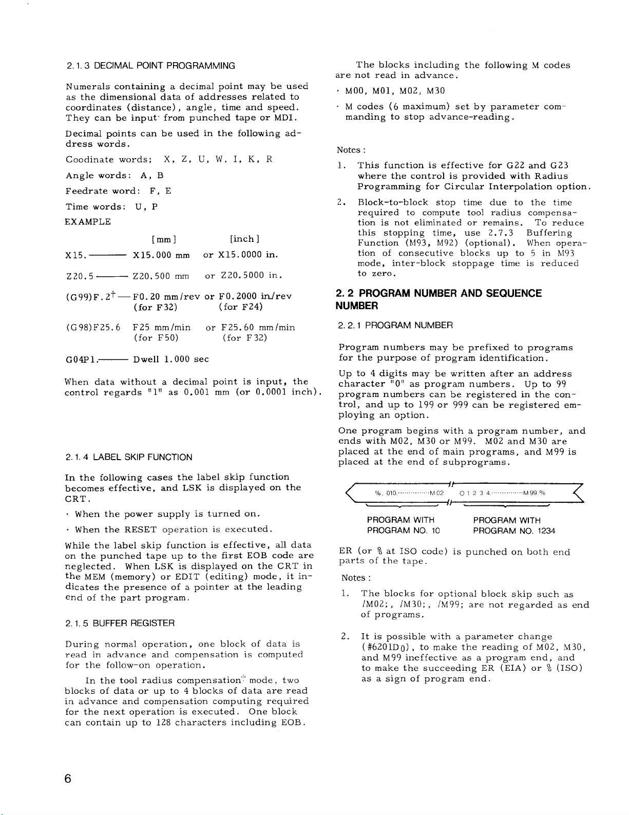
One program begins with a program number, and
ends with
placed at the end of main programs, and M99 is
placed at the end of subprograms.
ER (or % at 1S0 code) is punched on both end
parts of the tape.
Notes :
“O” as program numbers. Up to 99
M02, M30 or M99. M02 and M30 are
PROGRAM WITH PROGRAM WITH
PROGRAM NO. 10 PROGRAM No. 1224
1. The blocks for optional block skip such as
/M02; , /M30; ,
of programs.
It & possible with a parameter change
2.
(#6201Do) , to make the reading of M02, M30,
and M99 ineffective as a program end, and
to make the succeeding ER (EIA) or % (ISO)
as a sign of program end.
/M99; are not regarded as end
Page 15
2. 2.2 SEQUENCE NUMBER
2.3 COORDINATE WORDS
Integers consisting of up to 4 digits may be writ-
ten following an address character N as sequence
numbers.
Sequence numbers are reference numbers for
blocks, and do not have any influence on the
meaning and sequence of machining processes.
Therefore, they may be sequential, non-sequen-
tial, and duplicated numbers, also not using
any sequence number is possible.
sequential numbers are convenient as sequence
numbers.
When searching for sequence numbers, be sure
to search or specify program numbers beforehand.
Notes :
Generally,
1. Five or more digits must not be written as a
sequence number.
2.
When two or more blocks have the same sequence number, only one is retrieved and
read, and no more searching is performed.
3. Blocks without sequence numbers can also
be searched for with respect to the address
data contained in the blocks.
2.2.3.
Those blocks in which “ /n” (n = ( 1 - 9) is included are neglected between
that block, when the external
switch for that number “n” is
OPTIONAL BLOCK SKIP (h - /91+]
In and the end of
optional block skip
on.
Generally,
tions and commands for setting coordinate systems are called coordinate words, and coordinate
words consist of address characters for desired
axes and numerals representing dimensions of
directions.
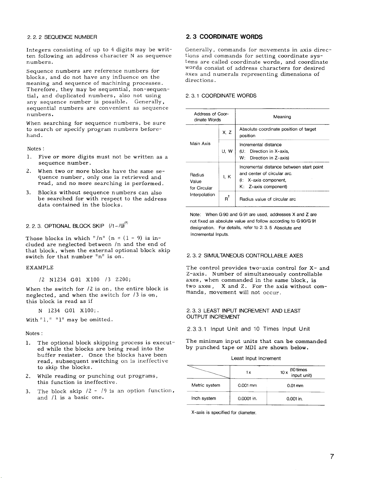
2.3.1
Address of Coordinate Words
Main Axis
Radius
Value
for Circular
Interpolation
Note: When G 90 and G 91 are used, addresses X and Z are
not fixed as absolute value and follow accofdi ng to G 90/G 91
designation. For details, refer to 2. 3.5 Absolute and
Incremental Inputs.
2.3.2 SIMULTANEOUS CONTROLLABLE AXES
commands for movements in axis direc-
COORDINATE WORDS
I
Absolute coordinate position of t~get
x,
z
position
Incremental distance
U, W (U: Direction in X-axis,
W: Direction in Z-axis)
Incremental distance between start point
and center of circular arc.
1, K
(1: X-axis component,
K: Z-axis component)
R’
Radius value of circular arc
—
+
1 I
I
I
I
Meaning
EXAMPLE
/2 N1234 GO1 x1OO /3
When the switch for /2 is on,
neglected, and when the switch for /3 is on,
this block is read as if
N 1234 GO1 xlOO; .
With “ 1, “
Notes :
The optional block skipping process is execut-
1.
ed while the blocks are being read into the
buffer resister. Once the blocks have been
read, subsequent switching on is ineffective
to skip the blocks .
2.
While reading or punching out programs,
this function is ineffective.
The block skip /2 - /9 is an option function,
3.
and /1 is a basic one.
1!l!! may be omitted.
Z200;
entire block is
the.
The control provides two-axis control for X- and
Z–axis.
axes, when commanded in the same block, is
two axes ,
mands, movement will not occur.
2.3.3
Number of simultaneously controllable
Xand Z. For the axis without com-
LEAST INPUT INCREMENT AND LEAST
OUTPUT INCREMENT
2,3,3.1
The minimum input units that can be commanded
by punched tape or MDI are shown below.
X-axis is specified for diameter,
Input Unit and 10 Times Input Unit
Least Input Increment
7
Page 16
2.3.3.1 Input Unit and 10 Times Input Unit
(Cent’d)
Inch/MM input is selected by setting #6001D0.
Inch/MM input selection by G20/G21 is optional.
Selection of multiplication factor xl /x10 is made
by parameter #6006D 5.
Tool offset value must always be written in O. 001
mm (or O. 0001 inch) , and offset is possible in
these units.
In O. 01 mm increment system, the following operation must be made in the unit of O. 01 mm.
. Programming for operation in TAPE mode.
o Write operation in MDI mode.
o Programming for operation in MEMORY mode.
. Program editing operation in EDT mode .
Notes :
If NC tape programmed by O. 001 mm is fed
1.
into or stored in an equipment set by O. 01
mm increment, the machine will move ten
times the intended dimensions.
If the increment system is switched when the
2.
contents of NC tape are stored in memory,
the machine will move by ten times or one
tenth of the commanded dimensions.
3.
When the stored program is punched out on
the tape+, the stored f?gures are punched
out “as stored” regardless of switching of
the increment system.
4.
Multiplication factor 10X (10 times the input
unit) is effective for distance command only.
It does not function on the designation of
time, angle”, etc.
10X is set as effective ( #6006D5 = 1) , the
same address word is multiplied by 10 or not
depending on type of G command.
EXAMPLE
G04 U...
GOO U...
;—Not multiplied by 10 (Time)
;— Multiplied by 10 (Distance)
When multiplication factor
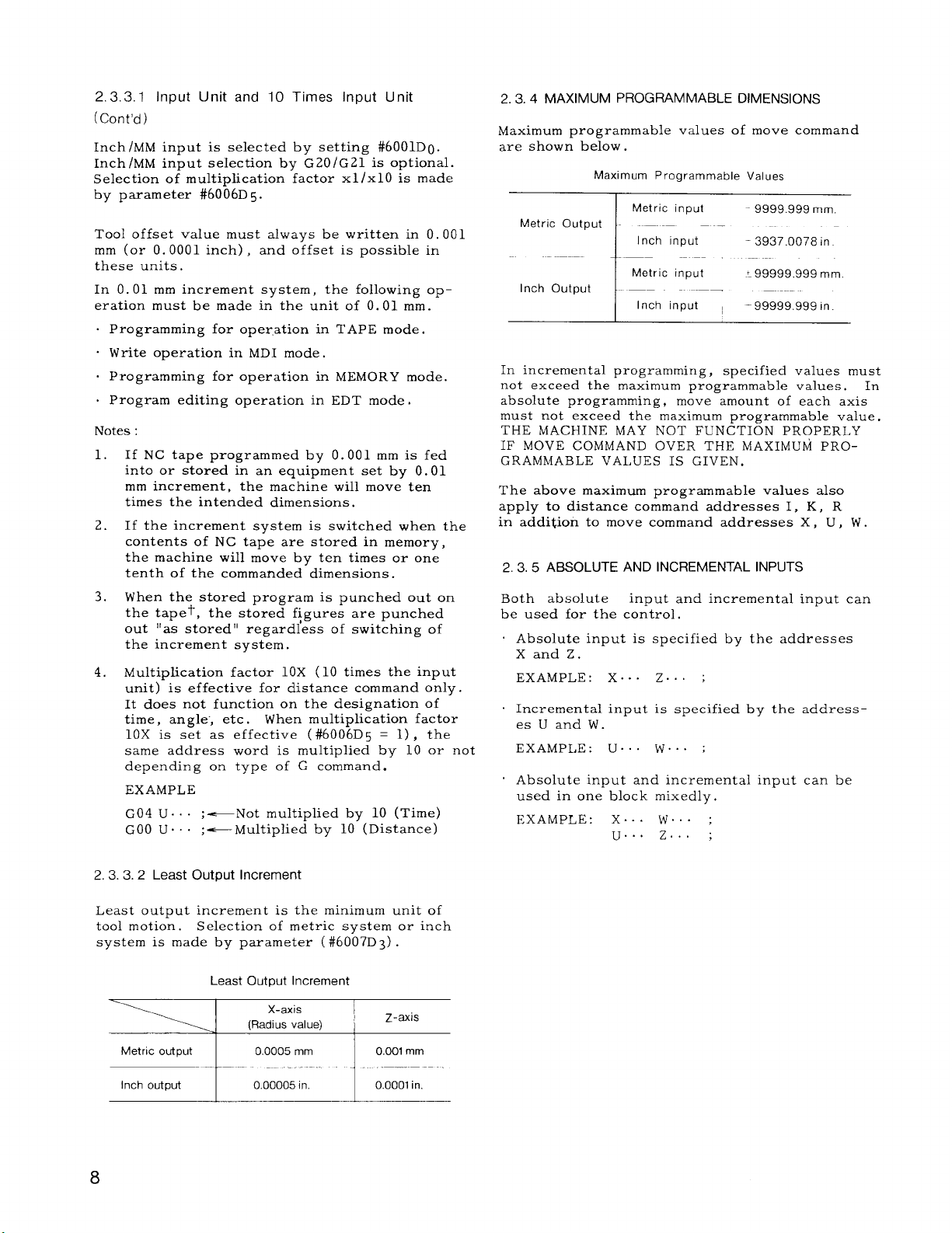
2.3.4 MAXIMUM PROGRAMMABLE DIMENSIONS
Maximum programmable values of move command
are shown below .
Maximum Programmable Values
Metric input
Metric Output — -—
Inch input
Metric input
Inch Output
Inch input I
-9999.999 mm.
—
-3937.0078 in
Y99999.999 mm.
‘99999 .999 in.
In incremental programming, specified values must
not exceed the maximum programmable values. In
absolute programming, move amount of each axis
must not exceed the maximum programmable value.
THE MACHINE MAY NOT FUNCTION PROPERLY
IF MOVE COMMAND OVER THE MAXIMUM PROGRAMMABLE VALUES IS GIVEN.
The above maximum programmable values also
apply to distance command addresses 1, K, R
in addition to move command addresses X , U , W .
2.3.5 ABSOLUTE AND INCREMENTAL INPUTS
Both absolute
be used for the control.
Absolute input is specified by the addresses
Xand Z.
EXAMPLE: X.. . Z.. ;
Incremental input is specified by the addresses U and W.
EXAMPLE: U.. . W., . ;
Absolute input and incremental input can be
used in one block mixedly.
EXAMPLE: X.. . W.. ;
input and incremental input can
u.. . z. ;
2, 3. 3.2 Least Output Increment
Least output increment is the minimum unit of
tool motion. Selection of metric system or inch
system is made by parameter (#6007D3) .
Least Output Increment
X-axis
“-”J !
Metric output
Inch output 0.00005 in. 0.0001 in.
--”1-””- ‘-”--””
(Radius value)
0.0005 mm 0.001 mm
Z-axis
“---”-
8
Page 17
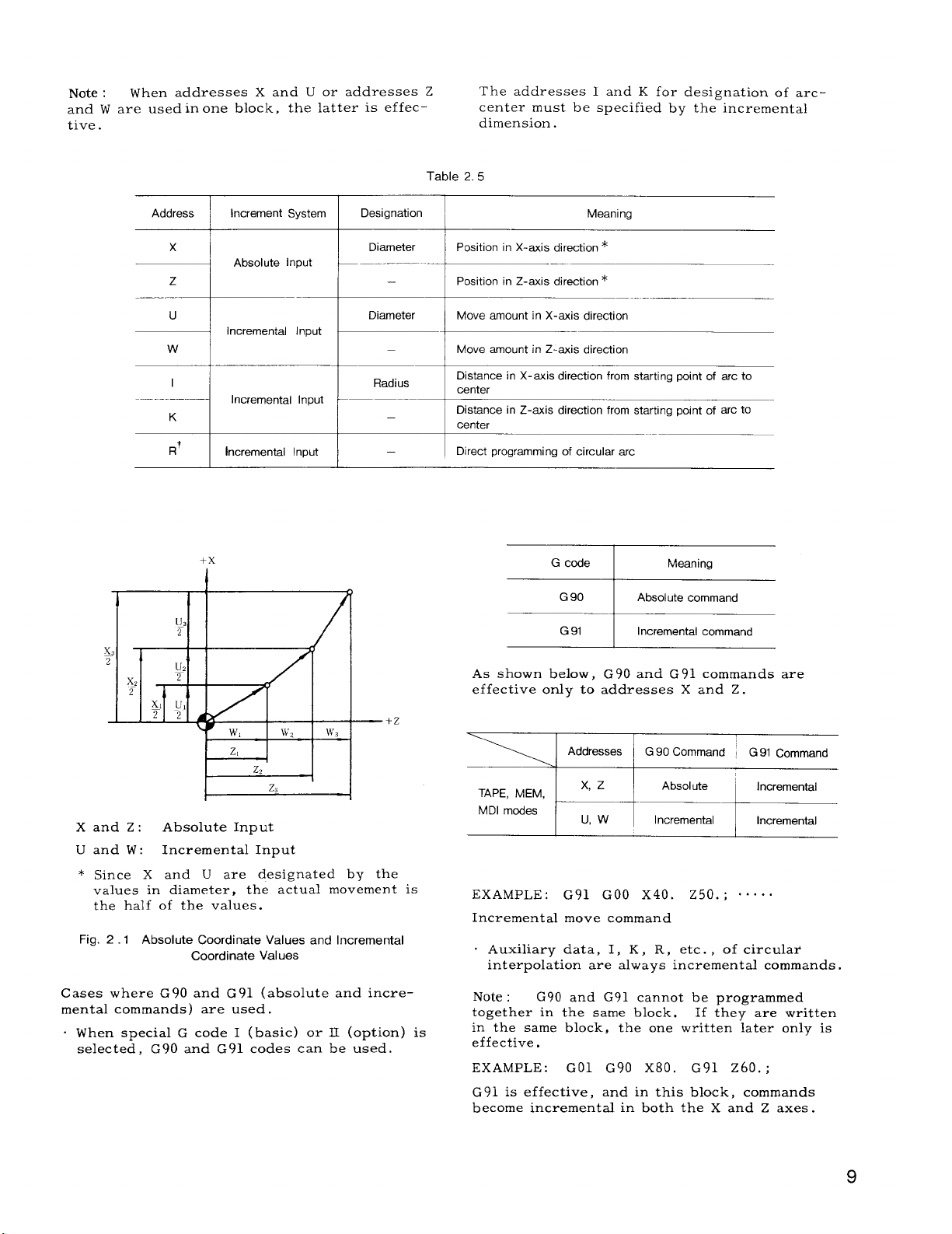
Note :
and W are used in one block, the latter is effec tive.
When addresses X and U or addresses Z
The addresses 1 and K for designation of arccenter must be specified by the incremental
dimension.
Table 2.5
Address
x
z
u
w
I
K
Increment System
Absolute Input
Incremental Input
incremental
Incremental Input
+x
I
Input
Designation
Diameter
—
Diameter
—
Radius
—
Meaning
Position in X-axis direction *
Position in Z-axis direction *
Move amount in X-axis direction
Move amount in Z-axis direction
Distance in X-axis direction from starting point of arc to
canter
Distance in Z-axis direction from starting point of arc to
center
Direct programming of circular arc
G code Meaning
G9CI I Absolute command
G 91
Incremental command
—+Z
b+--
Xand Z: Absolute Input
U and W: Incremental Input
* Since X and U are designated by the
values in diameter, the actual movement is
the half of the values.
Fig. 2.1
Cases where G 90
mental commands) are used.
. When special G code I (basic) or II (option) is
selected, G90 and G91 codes can be used.
Absolute Coordinate Values and Incremental
Coordinate Values
and G91 (absolute and incre-
As shown below, G90 and G 91 commands are
effective only to addresses X and Z.
Addresses
TAPE, tvfEtvf,
MDI modes
EXAMPLE :
Incremental move command
. Auxiliary data, 1, K, R, etc. , of circulai
interpolation are always incremental commands.
Note : G90 and G91 cannot be programmed
together in the same block. If they are written
in the same block, the one written later only is
effective.
EXAMPLE:
G 91 is effective, and in this block, commands
become incremental in both the X and Z axes.
~+ ,::::al*
G91 GOO X40. Z50. ; o“. . .
GO1 G90 x80. G91 z60. ;
G 90 Command ~ G 91 Command
Page 18
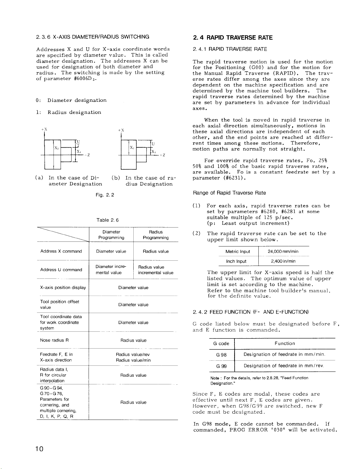
2.3.6 X-AXIS DIAMETER/RADIUS SWITCHING
2.4 RAPID TRAVERSE RATE
Addresses X and U for X–axis coordinate words
are specified by diameter value.
diameter designation.
used for designation of both diameter and
radius .
of parameter #6006D s.
o: Diameter designation
1: Radius designation
The switching is made by the setting
The addresses X can be
This is called
I I
w-zPP+z
(a) In the case of Di-
ameter Designation
(b) In the case of ra-
dius Designation
Fig. 2.2
Table 2.6
Diameter Radius
Programming
Programming
2. 4.1 RAPID TRAVERSE RATE
The rapid traverse motion is used for the motion
for the Positioning (GOO) and for the motion for
the Manual Rapid Traverse (RAPID) . The traverse rates differ among the axes since they are
dependent on the machine specification and are
determined by the machine tool builders. The
rapid traverse rates determined by the machine
are set by parameters in advance for individual
axes.
each axial direction simultaneously, motions in
these axial directions are independent of each
other,
ent times among these motions.
motion paths are normally not straight.
50% and 100% of the basic rapid traverse rates,
are available.
parameter (#6231) .
Range of Rapid Traverse Rate
(1) For each axis, rapid traverse rates can be
(2) The rapid traverse rate can be set to the
When the tool is moved in rapid traverse in
and the end points are reached at differ-
For override rapid traverse rates, Fo, 25%
Fo is a constant feedrate set by a
set by parameters #6280, #6281 at some
suitable multiple of 125 p /sec.
Least output increment)
(p:
uPPer limit shown below.
Therefore,
Address X command
Address U command
X-axis position display
Tool position offset
value
Nose radius R
Feedrate F, E in
X-axis direction
Radius data 1,
R for circular
interpolation
G90-G 94,
G70-G76,
Parameters for
cornering, and
multlple cornering,
D, 1, K, P, Q, R
“-*-”-
Diameter value
I
Diameter incre-
mental value ~ ~dius value
I
I
t
~
1 Incremental value
Diameter value
Diameter value
I
1
t
I
Radius value
Radius val uehev
Radius value/rein
Radius value
Radius value
Radius value
Metric Input
Inch Input
The upper limit for X-axis speed is half the
listed values. The optimum value of upper
limit is set according to the machine.
Refer to the machine tool builder’s manual,
for the definite value.
FEED FUNCTION (F- AND E-FUNCTION)
2.4.2
G code listed below must be designated before F ,
and E function is commanded.
G code I
G 98
G99
Note : For the details, refer to 2.8.28, “Feed Function
Designation.”
Since F, E codes are modal, these codes are
effective until next F , E codes are given.
However, when G98/G99 are switched, new F
code must be designated.
In G98 mode, E code cannot be commanded. If
commanded, PROG ERROR “030” will be activated.
I 24,000 mmlmin
i
2,400 inlmin
I
Function
Designation of feedrate in mm/min.
Designation of feedrate in mm/rev.
Page 19
2.4. 2.1 Feed Per Revolution (G99 Mode)
(1) Tool feed per revolution of the spindle can
be specified with F (normal feed) or E ( fine
feed) .
(2) The feed ranges that can be specified by
the F and E codes are as follows.
Mode, F and E Feed Ranges
G 99
of Feed/Revel ution
Range
Metric
Metric
output
Inch
output
These feed ranges are subject to the following
restrictions depending on the spindle speed S.
Notes :
1.
2.
3.
input
Inch I
input
Metric
, input
Inch
input
Metric output
Inch output
Notes :
1. Program feed per revolution within such a range that the
X-axis component remains below 12,000 mm/min or
1,200 in./min.
2. This uppar limit may still be reduced by the performance
limit of the machine.
Refer to the machine tool builder’s manual.
A command “FO” causes data errors.
Any minus value should not be specified for
F commands.
not operate properly.
EXAMPLE
F-250 ; . . . . . Wrong
Feedrate commands in the direction of the
X–axis must be given in radius.
F 32
E34
F 24
E 26
I
F 32
E34
F 24
E 26 F O.000010-E 50.00C0OO in/rev
F 0.01- F 500.00 mm/rev
E 0.0001- E 500.0000 mmlrev
~
F 0.0301 –F19.6Ek50 in./rev
I
E0.000004–E 19.685000
1
F 0,01 –F1270.00 mmlrev
E 0.0003-E 1270.0000 mmlrev
FO.001 –F 50.0000 in./rev
I F(E) XS~24,000mm/min
F(E)XS S 2,400 in./min
I
If specified,
the machine will
in./rev
EXAMPLE
G99 S350 (r/rein) ;
GO1 U1OO. F200 ;
In the above case, the feedrate is:
F x S = 2.0 mm/rev. x 35o r/rein
= 700 mm/m~n
. . . In case of F32.
+x
ql
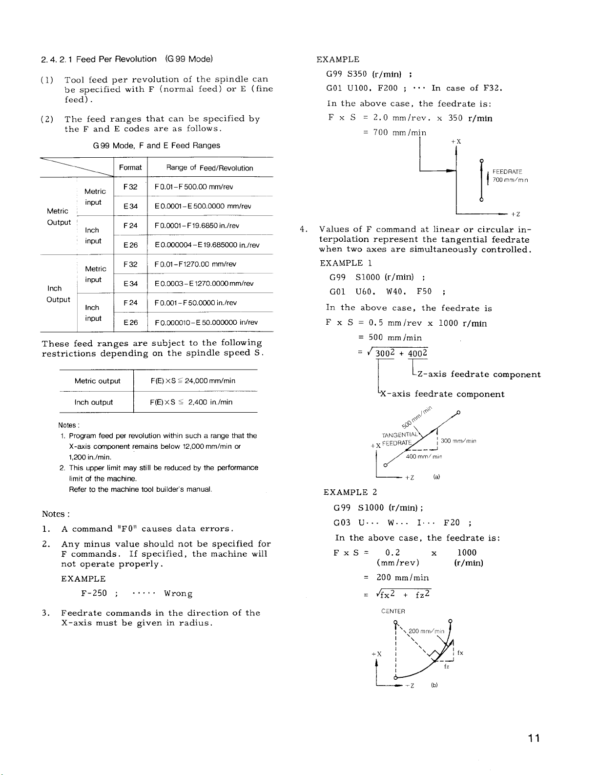
4.
Values of F command at linear or circular in–
terpolation represent the tangential feedrate
when two axes are simultaneously controlled.
EXAMPLE 1
G99 S1OOO (r/rein) ;
GO1 U60, W40. F50 ;
In the above case, the feedrate is
x S = 0, 5 mm/reV x Io(lf) r/rein
F
500 mm/min
=
~3002 + 4002
rr
I
I
‘X–axis feedrate component
TANGENTIAL
FEEDFIATE
+x
I
IO’
~ .Z
EXAMPLE 2
G99 s1OOO (r/rein) ;
G03 U.. - W.. . I
In the above case,
FxS= 0.2
(mm/rev)
= 200 mm/min
. 4fx2 + fz2
CENTER
Lz-axis feedrate component
~.o
#+
@~
~ 300 mm/mln
——-
400 mm/mln
x
(a)
. . F20 ;
the feedrate is:
1000
x
(r/rein)
FEEDRATE
700 mm/mn
I
+x
t
L---- .Z
fx
(b)
11
Page 20

2.4. 2.2 Feed Per Minute (G 98 Mode)
(1) Tool feed can be specified in mm/min or
in/rein with F codes .
(2) The feed range that can be programmed
with F codes is as follows.
Mode F Code Feed Range
G 98
EXAMPLE 1
G98 ;
GO1 u60.
In this case,
F =
500 = ~3002 + 4002
(mm/min)
W40. F500 ;
~ ~-a~i~
Lx-axis component
component
Notes :
1. Program feed-per-minute values so that the X-axis speed
ccmponent wi II not exceed half the above upper limit
feedrates.
EXAMPLE
G98 GOI U300. F1200’
(Metric output, metric input)
2. The upper limit value is further subject to the limitation
impoeed by the machine performance. Refer to the
machine tool build&s manual. This upper limit value is
to be set in parameter #6228
Notes :
Do not write F command in FO or negative
1.
values.
Commands in the X-axis direction indicate
2.
speeds in radius.
Example
G98;
GO1 X200. F700 ;
F 700
—!
FEEDRATE
700 mm,’mlq
-!-+
l——————+,
Values of F command at linear or circular
interpolation represent the tangential feed-
rate when two axes are simultaneously controlled.
EXAMPLE 2
G98 ;
G03 X.. . Z.. . 1.. . F200 ;
In this case,
F=200=ifxZ+fz Z
(mm/min)
CENTER
–x
I
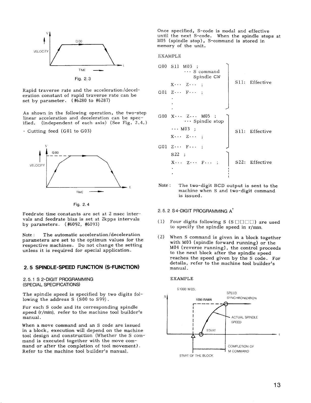
2,4.3 AUTOMATIC ACCELERATION AND
DECELERATION
Acceleration and deceleration for rapid traverse
and for cutting feed are automatically performed
without programming ,
2.4. 3.1
Traverse and Manual Feed
In the following operation, the pattern of automatic acceleration and deceleration is linear.
(See Fig. 2.3. )
Acceleration and Deceleration of Rapid
Positioning (GOO)
Manual rapid traverse (RAPID)
Manual continuous feeding (JOG)
Manual HANDLE feeding (HANDLE)
12
Page 21
Once specified,
until the next S-code.
M05 (spindle stoD) ,
memor~ of the u~it.
EXAMPLE
S-code is modal and effective
When the spindle stops at
S-command is stored in
TIME —
Fig. 2.3
Rapid traverse rate and the acceleration /deceleration constant of rapid traverse rate can be
set by parameter. ( #6280 to #6287)
As shown in the following operation, the two–step
linear acceleration and deceleration can be specified. (independent of each axis) (See Fig. 2.4. )
o Cutting feed (GO1 to G03)
v
G00
.———
P
VELOCITY
TIME —
Fig. 2.4
Feedrate time constants are set at 2 msec intervals and feedrate bias is set at 2kpps intervals
by parameters. ( #6092, #6093)
Note : The automatic acceleration /deceleration
parameters are set to the optimum values for the
respective machines.
unless it is required for special application.
SPINDLE-SPEED FUNCTION (S-FUNCTION)
2.5
Do not change the setting
t
GOO S11 M03 ;
. . . S command
Spindle CW
Sll:
x.. . z.. . ;
GO1 Z.. . F.. . ;
1
GOO X.. . Z.. . M05 ;
GO1 Z.. . F.. . ;
Note :
2.5.2 S4-DIGIT
(1) Four digits following S (S ❑ ❑ ❑ ❑ ) are used
. . c Spindle stop
..-M03 ;
x.. . z.. . ;
S22 ;
. . .
x
z.. . F.. .
The two-digit
machine when
is issued.
1
BCD output is sent to the
S and two-digit command
PROGRAMMING AT
to specify the spindle speed in r/rein.
Effective
Effective
Sll:
S22: Effective
(2) When S command is given in a block together
with M03 (spindle forward running) or the
M04 (reverse running) , the control
to the next block after the spindle speed
reaches the speed given by the S code. For
details, refer to the machine tool builder’s
manual.
proceeds
2.5,1 S 2-DIGIT PROGRAMMING
(SPECIAL SPECIFICATIONS)
The spindle speed is specified by two digits fol-
lowing the address S (S00 to S99) .
For each S code and its corresponding spindle
speed (r/rein), refer tO the machine tool builder’s
manual.
When a move command and an S code are issued
in a block, execution will depend on the machine
tool design and construction (Whether the S command is executed together with the move com–
mand or after the completion of tool movement) .
Refer to the machine tool builder’s manual.
EXAMPLE
s
S1OOO M03,
1000 FUMIN
———— . .
1I
I
I
I
u
START OF THE BLOCK
SPEED
SYNCHRONIZATION
ACTUAL SPINDLE
~
SPEED
t
13
Page 22

2. 5.2 S 4-DIGIT PROGRAMMING A+(Cont’d)
(3) S
commands are modal. Although the spindle stops at the M05 command, the S command is retained.
Therefore, when M03
(or M04) is given, the spindle runs accord-
ing to the S command.
(4) When S command is changed after the spin-
dle start by M03 or M04, S command should
be given within the range of spindle speed
selected by spindle gear.
Notes :
1.
The lower limit of the spindle speed depends
on the spindle drive. Refer to the machir,e
tool builder’s manual for the low-speed limit.
Negative S commands must not be programmed.
2.
When the control is provided with the S 4digit command function, the “Spindle speed
override” option can be built into it.
3.
With machine tools with which the main spindle gear ratio changes can be specified by
M codes, first write the applicable M code
to preselect the desired gear ratio, and then,
write the S command.
Refer to the data of
the machine tool builder for the number of
gear ratios, the speeds at various gear ratios,
and other details.
4.
When the control is provided with this func -
tion, the spindle maximum speed commanding
function with the instruction “G50 S . . . ; “
can be used.
2. 5.3 S 4-DIGIT
This function is to modify the S4-digit com-
(1)
PROGRAMMING B+
mand A output freely through the programmable machine interface.
(2) Basically, this function is used in the same
as the S 4-digit command A function,
way
but it is normally used to set the manually
controlled spindle speeds controlled by the
rotary switch on the m“achine control station
corresponding to S command speeds. For
the details of S command speeds, refer to
the machine tool builder’s manual.
TOOL FUNCTiON (T-FUNCTION)
2.6
2.6.1 T 4-DIGIT PROGRAMMING
Four digits following the address T specifies
(1)
the tool number.
TDDDU
(2) For applicable tool number to be specified,
refer to the machine tool builder’s manual .
Notes :
1. When the tool number is changed by the T
command, a turret lathe begins to index the
tool instantaneously.
Therefore, the turret
should be removed, before the command,
from the area where” an accidental collision
might occur.
Tool offset number 00 cancels the tool offset.
2.
2.6.2 TOOL OFFSET MEMORY+
The area in which tool position offset values, tool
radius compensation values, and other compensa-
tion data are stored is called Offset Memory .
(1) The entire memory areas of Offset Memory
including the options are as shown below.
OFFSET MEMORY NO
[
‘TOOL OFFSET
MEMORY
,50 GROUP5MA: f ‘---’”--- ‘--- ~:~i;:;
“TOOL COORDINATE
MEMORY — \
(49 GROUPS MAXI ‘g
“TOOL RADIUS
MEMORY
Note :
For the actually usable range within the
above Offset Memory,
builder’s manual.
(2)
The “tool offset Nos. “
function directly correspond to the “offset
memory Nos. , “
for various compensations.
tool coordinate memory Nos. ( for setting the
work coordinate system) correspond to the
tool selection Nos . in the T function . The
work coordinate shift memory is an independent function, not related to the T function. )
Ii –_-–
---
I ;0
51
1
‘I&/
-r-
refer to the machine tool
specified by the T
and their contents are used
However, the
-MEMORY
J SUPPLEMENT
14
Tool offset number
(O - 160r 50)
1
Tool selection
Page 23
(3) Write these data in the memory, before start-
ing to operate the machine under automatic
co; trol. to 4.3.5, “ Displaying and Writing Tool Offset
Values .“
Memory, follow the procedure described in
6.2.3, “ Work Measurement Value Direct Input *.”
TOOL POSITION OFFSETS
2.6.3
When the tool offset number is specified, the off-
set value corresponding to the tool offset number
is added algebraically to the command value in
the program and the tool is moved to the offset
position.
coordinate values of the programmed tool tip and
the actual tool tip must be stored into tool offset
memory in advance as the offset value.
When the coordinate value of the actual tool tip
has changed due to tool wear or some other reasons, the tool position offset values should be
set again.
attained without correcting the program.
(1) Range of tool position offset value
The programmable range of tool offset value
is shown below.
For the writing procedure, refer
For writing into Tool Coordinate
Therefore, the difference between the
Thus, the programmed machining is
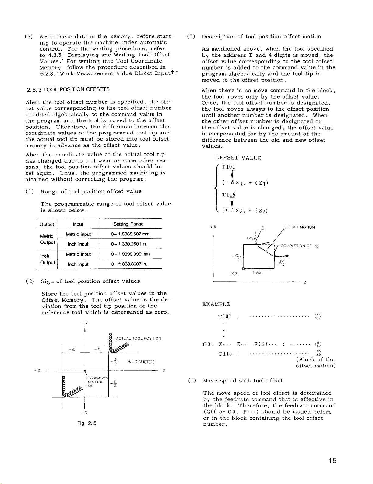
Description of tool position offset motion
(3)
As mentioned above, when the tool specified
by the address T and 4 digits is moved, the
offset value corresponding to the tool offset
number is added to the command value in the
program algebraically and the tool tip is
moved to the offset position.
When there is no move command in the block,
the tool moves only by the offset value.
Once, the tool offset number is designated,
the tool moves always to the offset position
until another number is designated. When
the other offset number is designated or
the offset value is changed, the offset value
is compensated for by the amount of the
difference between the old and new offset
values.
OFFSET VALUE
T101
T
(+6X1, + 6z~)
T115
T
I
(+ 6X2, + 6Z2)
input I o- f9999.999rnnl
Inch
out put
(2) Sign of tool position offset values
store the tool position offset values in the
Offset Memory.
viation from the tool tip position of the
reference tool which is determined as zero.
z
Metric
Inch input
tiOLpO’’T’oN
I
I J.
Fig. 2.5
,
O–
I
The offset value is the de-
+x
I I
P~OGnAtMMED
–x
fE@3.&307in.
6“
_
I& DIAMETER)
~
+Z
+x
,,1+
L!x~
+
(X,z)
EXAMPLE
‘Tlol ; . . . . . . . . . . ...+...”..
GO1 X.. . Z.. .
T115 ; . . . . . . . . . . . . . .
(4) Move speed with tool offset
The move speed of tool offset is determined
by the feedrate command that is effective in
the block.
(GOO or GO1 F
or in the block containing the tool offset
number.
Therefore, the feedrate command
{3
8Z2 :
+-
-—
7L?z.
F(E) . . . ; .
..) should be issued before
OFFSET MOTION
1
COMPLETION OF @
.-
-8KL
2
. . . . . .
. . . . .
( Block of the
offset motion)
a
a
B
15
Page 24
---—— —————.
25
3 TOOL POSITION OFFSETS (Cent’d)
EXAMPLE
EXAMPLE
G50 X.. . 2.. . ;
GOO S.. .
Instructions for commanding tool position
(5)
offset
Tool position offset is executed by designating the tool offset number corresponding to
the actual tool must be designated.
Tool offset starts at the block in which the
a.
T-code is commanded. When T–code is read,
the tool selection signal ( BCD) is fed and
the tool starts to move by the offset value
corresponding to the tool offset number.
Since T code is modal, it is retained until
the other T code is designated.
EXAMPLE
GOO T0202 ; . . . The tool number N 02 is
M03 TO1O8 ;
x.. . z.. . ;
selected. Tool offset
motion is made accord–
ing to the contents of
the tool offset number 02.
Off set mot ion is
made at the rapid
traverse rate.
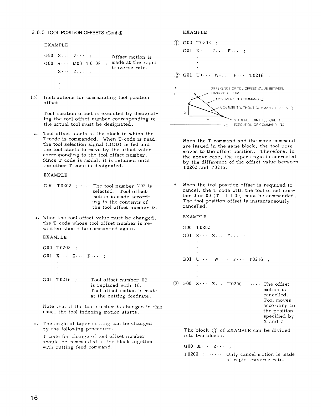
~ GOO T0202 ;
GO1 X.. . Z.. . F.. . ;
~ GO1 U+. . . W-. . . F.. . T0216 ;
-x
I
/
T
,.L ‘
DICFER~NcE ,OE ~~L OFFSET l/AL~JE 3ET’,vEEN
T0216 AhD T 0202
MOVEMEN” OF COMMAND ~,
, UOVEMENT wITHO IIT CCIMMAN17 T07. R Ih <
-~1 ~- ‘- ‘-” - ‘-
–;y
~
When the T command and the move command
are issued in the same block, the tool nose
moves to the offset position.
the above case,
by the difference of the offset value between
T0202 and T0216.
d . When the tool position offset is required to
cancel, the T code with the tool offset number O or 00 (T
The tool Dosition offset is instantaneously
cancelled~
“-=.
STARTING POINT (BEFOQE THE
EXECUTION OF COMMAND ~,,
.Z
Therefore, in
the taper angle is corrected
❑ ~ 00) must be commanded.
When the tool offset value must be changed,
b.
the T–code whose tool offset number is re–
written should be commanded again.
EXAMPLE
GOO T0202 ;
GO1 X.. . Z.. . F.. . ;
GO1 T0216 ;
Note that if the tool number is changed in this
case, the tool indexing motion starts.
The angle of taper cutting can be changed
c.
Tool offset number 02
is replaced with 16.
Tool offset motion is made
at the cutting feedrate ,
by the following procedure.
T code for change of tool offset number
should be commanded in the block together
with cuttin~ feed command .
EXAMPLE
GOO T0202
GO1 X.. . Z.. . F.. . ;
GO1 U+. . . W-. . . F.. .
@ GOO X.. . Z.. . T0200
The block ~ of EXAMPLE can be divided
into two blocks.
G(IO X.. . Z.. . ;
T0200 ; . . . . . Only cancel motion is made
at rapid traverse rate.
ro216 ;
. . . .
The offset
motion is
cancelled.
Tool moves
according to
the position
specified by
Xand Z.
Page 25
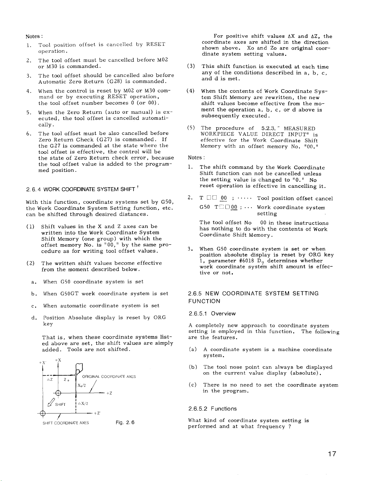
Notes :
Tool position offset is cancelled by RESET
1.
operation.
2.
The tool offset must be cancelled before M02
or M30 is commanded.
The tool offset should be cancelled also before
3.
Automatic Zero Return ( G 28) is commanded.
When the control is reset by M02 or M30 com-
4.
mand or by executing RESET operation,
the tool offset number becomes O (or 00) .
When the Zero Return (auto or manual) is ex-
5.
ecuted, the tool offset is cancelled automati–
tally.
The tool offset must be also cancelled before
6.
zero Return Check ( G27) is commanded. If
the G27 is commanded at the state where the
tool offset is effective, the control will be
the state of Zero Return check error, because
the tool offset value is added to the program–
med position.
WORK COORDINATE SYSTEM SHIFT i
2.6.4
With this function, coordinate systems set by
the Work Coordinate System Setting function,
can be shifted through desired distances.
Shift values in the X and Z axes can be
(1)
written into the Work Coordinate System
Shift Memory (one group ) with which the
offset memory No. is
cedure as for writing tool offset values.
(2)
The written shift values become effective
from the moment described below,
G50 coordinate system is set
When
a.
“ 00, ” by the same pro-
G50,
etc.
For positive shift values AX and AZ, the
coordinate axes are shifted in the direction
shown above. Xo and Zo are original coordinate system setting values.
(3)
This shift function is executed at each time
any of the conditions described in a, b, c,
and d is met.
(4)
When the contents of Work Coordinate Sys-
tem Shift Memory are rewritten, the new
shift values become effective from the mo-
ment the operation a, b, c, or d above is
subsequently executed,
(5)
The procedure of
WORKPIECE VALUE DIRECT INPUT” is
effective for the Work Coordinate Shift
Memory with an offset memory No, “00. “
Notes :
The shift command by the Work Coordinate
1.
Shift function can not be cancelled unless
the setting value is changed to “O. “
reset operation is effective in canceling it.
T~noO ;. . . . .
2.
—
5.2.3, “
Tool position offset cancel
MEASURED
G50 T~UOJ; . . . Work coordinate system
setting
The tool offset No
has nothing to do with the contents of Work
Coordinate Shift Memory.
3.
When G50 coordinate system is set or when
position absolute display is reset by ORG key
1, parameter #6018 D7 determines whether
work coordinate system shift amount is effective or not.
00 in these instructions
NO
G50GT work coordinate system is set
When
b.
When
c.
d,
automatic coordinate system is set
Position Absolute display is reset by ORG
key
That is, when these coordinate systems listed above are set, the-shift values are simply
added.
-v,
4
. .
. .
~
Tools are not shifted.
-x
20
ORIGINAL COORDINATE
z
AXES
Xoi2
+2
p%
SHIFT ,
8
~+z
SHIFT COORDINATE AXES
—
I AX,12
Fig. 2.6
NEW COORDINATE SYSTEM SETTING
2,6.5
FUNCTION
2.6.5.1 Overview
A completely new approach to coordinate system
setting is employed in this function.
are the features.
(a) A coordinate system is a machine coordinate
system.
(b) The tool nose point can always be displayed
on the current value display (absolute) .
(c) There is no need to set the coordinate system
in the program.
2.6.5,2
What kind of coordinate system setting is
performed and at what frequency ?
Functions
The following
17
Page 26
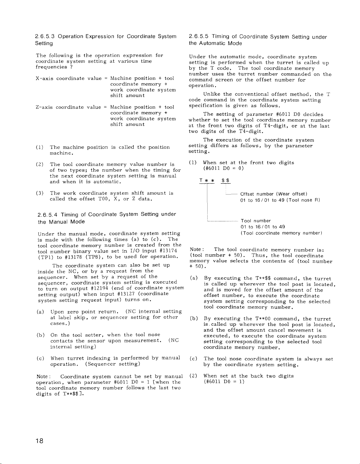
2.6.5.3 Operation Expression for Coordinate System
Setting
2.6.5,5 Timing of Coordinate System Setting under
the Automatic Mode
The following
coordinate system setting at various time
frequencies ?
X-axis coordinate value = Machine position + tool
is the operation expression for
coordinate memory +
work coordinate system
shift amount
Z-axis coordinate value = Machine position + tool
coordinate memory +
work coordinate system
shift amount
( 1) The machine position is called the position
machine.
The tool coordinate memory value number is
( 2 )
of two types; the number when the timing for
the next coordinate system setting is manual
and when it is automatic.
(3) The work coordinate system shift amount is
called the offset TOO, X, or Z data.
2.6.5,4 Timing of Coordinate System Setting under
the Manual Mode
Under the manual mode, coordinate system setting
is made with the following times (a) to (c) .
tool coordinate memory number is created from the
tool number binary value set in 1/0 input #13174
(TP1) to #13178 (TP8) , to be used for operation.
The
The coordinate system can also be set up
inside the NC,
sequencer.
or by a request from the
When set by a request of the
sequencer, coordinate system setting is executed
to turn on output #12194 (end of coordinate system
setting output) when
system setting request input) turns on.
(a) Upon zero point return. (NC internal setting
input #13127 (coordinate
at label skip, or sequencer setting for other
cases. )
(b) On the tool
contacts the sensor upon measurement.
setter, when the tool nose
(NC
internal setting)
Under the automatic mode, coordinate system
setting is performed when the turret is called up
by the T code.
number uses the turret number commanded on the
command screen or the offset number for
operation.
Unlike the conventional offset method, the T
code command in the coordinate system setting
specification is given as follows.
The setting of parameter #6011 DO decides
whether to set the tool coordinate memory number
at the front two digits of T4-digit, or at the last
two digits of the T4-digit,
The execution of the coordinate system
setting differs as follows, by the parameter
setting.
(1) When set at the front two digits
(#6011 DO = O)
T** $$
T—
~
,_
—— Tool number
Note :
(tool number + 50).
memory value selects the contents of (tool number
+ 50).
(a)
The tool coordinate memory number is:
By executing the T**$$ command, the turret
The tool coordinate memory
— Offset number (Wear offset)
01 to 16/01 to 49 (Tool nose R)
01 to 16/01 to 49
(Tool coordinate memory number)
Thus, the tool coordinate
is called up wherever the tool post is located,
and is moved for the offset amount of the
offset number, to execute the coordinate
system setting corresponding to the selected
tool coordinate memory number.
(b)
By executing the T**OO command, the turret
is.called up wherever the tool post is located,
and the offset amount cancel movement is
executed, to execute the coordinate system
setting corresponding to the selected tool
coordinate memory number,
(c) When turret indexing is performed by manual
operation,
Note :
operation, when parameter #6011 DO = 1 [when the
tool coordinate memory number follows the last two
digits of T**$$I.
Coordinate system cannot be set by manual
(Sequencer setting )
18
(c)
The tool nose coordinate system is always set
by the coordinate system setting.
(2)
When set at the back two digits
(#6011 DO = 1)
Page 27
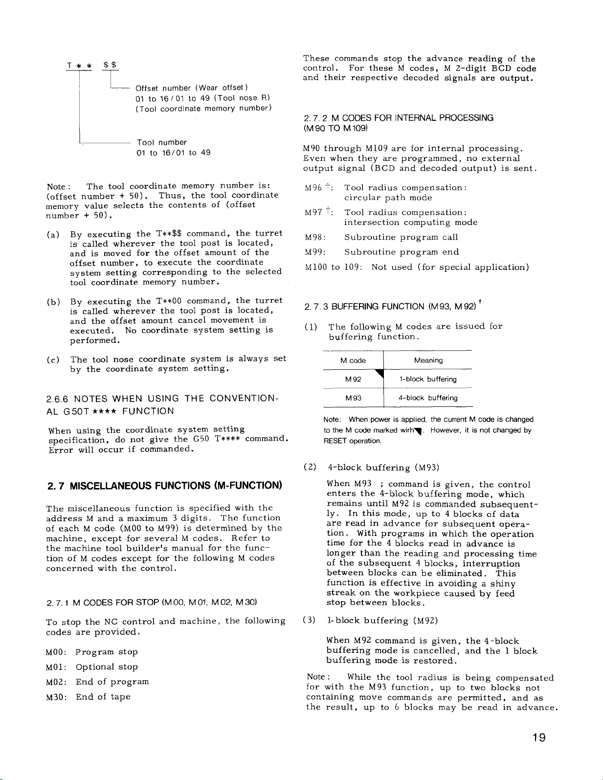
T** $$
-l-T
1,
L—
Offset number (Wear offset )
01 to 16/01 to 49 (TooI nose R)
(Tool coordinate memory number)
Tool number
01 to 16/01 to 49
These commands stop the advance reading of the
control. For these M codes, M 2–digit BCD code
and their respective decoded signals are output.
2.7.2 M CODES FOR INTERNAL PROCESSING
(M 90 TO M 109)
M90 through M109 are for internal processing.
Even when they are programmed, no external
output signal (BCD and decoded output) is sent.
Note :
(offset number + 50).
memory value selects the contents of (offset
number + 50) .
(a)
(b)
(c)
2.6.6
The tool coordinate memory number is:
By executing the T**$$ command, the turret
is called wherever the tool post is located,
and is moved for the offset amount of the
offset number, to execute the coordinate
system setting corresponding to the selected
tool coordinate memory number.
By executing the T**OO command, the turret
is called wherever the tool post is located,
and the offset amount cancel movement is
executed.
performed.
The tool nose coordinate system is always set
by the coordinate system setting.
No coordinate system setting is
Thus, the tool coordinate
NOTES WHEN USING THE CONVENTION-
AL G50T **** FUNCTION
When using the coordinate system setting
specification, do not give the G50 T**** command.
Error will occur if commanded.
MISCELLANEOUS FUNCTIONS (M-FUNCTION)
2.7
The miscellaneous function is specified with the
address M and a maximum 3 digits.
of each M code (MOO to M99) is determined by the
machine, except for several M codes.
the machine tool builder’s manual for the func-
tion of M codes except for-the following M codes
concerned with the control.
I M CODES FOR STOP (M 00, M 01, M 02, M 30)
2.7.
The function
Refer to
M96 -?:
M97 ‘:
M98:
M99:
M100 to
Tool radius compensation :
circular path mode
Tool radius compensation:
intersection computing mode
Subroutine program call
Subroutine program end
109: Not used ( for special application)
2.7.3 BUFFERING FUNCTION (M 93, M 92)+
The following M codes are issued for
(1)
buffering function.
M93 I 4-tIlock buffering
Note: When power is applied the current M code is changed
to the M code maked wirh~. However, it is not changed by
RESET operation.
(2)
4-block buffering (M 93)
When M93
enters the 4-block buffering mode, which
remains until M92 is commanded subsequent-
In this mode, up to 4 blocks of data
ly .
are read in advance for subsequent opera–
tion.
time for the 4 blocks read in advance is
longer than the reading and processing time
of the subsequent 4 blocks, interruption
between blocks can be eliminated. This
function is effective in avoiding a shiny
streak on the workpiece caused by feed
stop between blocks .
t
; command is given, the control
With programs in which the operation
To stop the NC control and machine, the following
codes are provided.
MOO:
MO1:
M02:
M30:
Program stop
Optional stop
End of program
End of tape
1-block buffering (M92)
(3)
When M92 command is given,
buffering mode is cancelled,
buffering mode is restored.
Note :
for with the M93 function , up to two blocks not
containing move commands ar-e permitted , and as
the result, up to 6 blocks may be read in advance.
While the tool radius is
the 4-block
and the 1 block
being compensated
19
Page 28
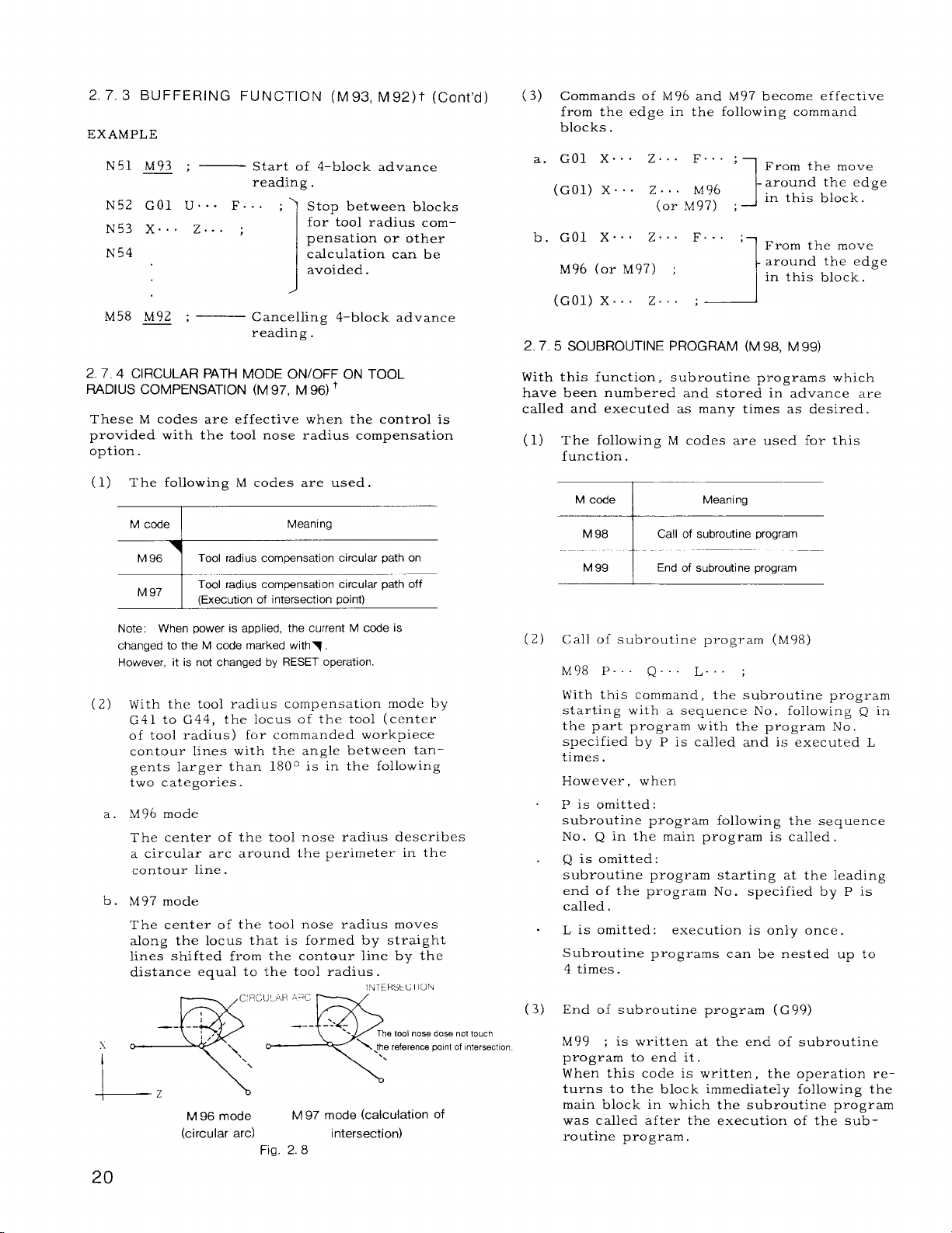
2. 7.3 BUFFERING FUNCTION (M93, M92)t (Cent’d)
EXAMPLE
N51 M93 ; —
N52 GO1 U.. - F.. . ;
N53 X.. . Z.. . ;
N54
M58 M92 ; — Canceling 4–block advance
Start of 4-block advance
reading .
Stop between blocks
for tool radius com
pensation or other
calculation can be
avoided.
1
reading .
(3) Commands of M96 and M97 become effective
from the edge in the following command
blocks .
a. GO1 X.. . Z.. . F.. ;
(GO1) X.. Z.. . M96
(or M97) ;
b. GO1 X.. Z.. . F.. . ;
M96 (or M97) ;
(G 01) X... Z.. ;
1 From the move
around the edge
in this block,
J
From the move
around the edge
in this block.
-1
2.7.5 SUBROUTINE PROGRAM (M 98, M 99)
2.7.4 CIRCULAR PATH MODE ONIOFF ON TOOL
RADIUS COMPENSATION (M 97, M 96)+
These M codes are effective when the control is
provided with the tool nose radius compensation
option.
(1) The following M codes are used.
M cede
M 96 1 Tool radius compensation circular path on
M 97
Note: When power is applied, the current M code is
changed to the M code m=ked with~
However, it is not changed by RESET operation.
(2)
With the tool radius compensation mode by
Tool radius compensation circular path off
(Execution of intersection point)
G41 to G44, the locus of the tool (center
of tool radius) for commanded workpiece
contour lines with the angle between tan–
gents larger than 180° is in the following
two categories.
M96 mode
a
The center of the tool nose radius describes
a circular arc around the perimeter in the
contour line.
b
M97 mode
The center of the tool nose radius moves
along the locus that is formed by straight
lines shifted from the contour line by the
distance equal to the tool radius.
Meaning
lNTFFiSELll ON
With this function, subroutine programs which
have been numbered and stored in advance are
called and executed as many times as desired.
(1) The following M codes are used for this
function.
M code
(2)
Call of subroutine program (M98)
M98 P.. . Q.. . L.. . ;
With this command, the subroutine program
starting with a sequence No. following Q in
the part program with the program No
specified by p is called and is executed L
times.
However, when
I
P is omitted:
subroutine program following the sequence
No. Q in the main program is called.
Q is omitted:
subroutine program starting at the leading
end of the program No. specified by P is
called.
L is omitted:
Subroutine programs can be nested up to
4 times.
End of subroutine program (G99)
Meaning
execution is only once.
.1
I
=Q!c3:000’nO”dO’‘3)
\
—z
M 96 mode
(circular arc)
‘b
M 97 mode (calculation of
Fig. 2.8
~,t~ reference pan! of lmtemacfmn.
\
intersection)
is written at the end of subroutine
;
M99
program to end it.
When this code is written, the operation returns to the block immediately following the
main block in which the subroutine program
was called after the execution of the subroutine program.
Page 29
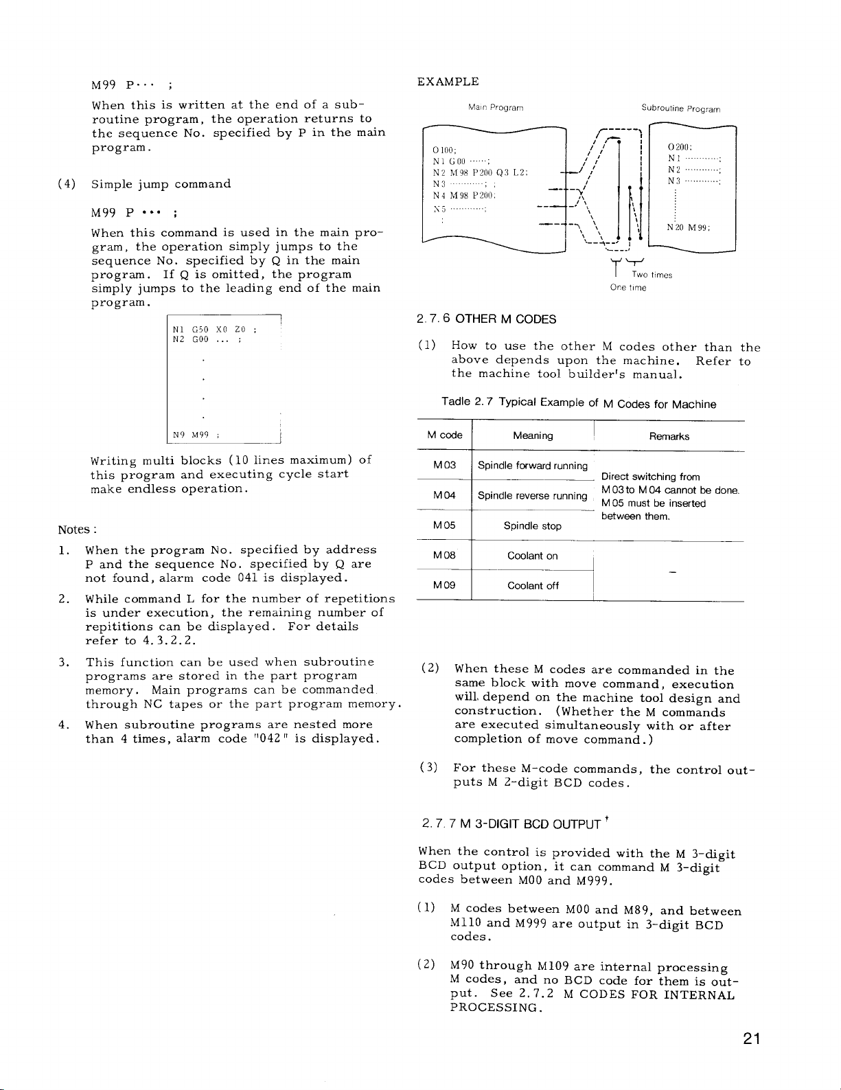
M99 P.. . ;
When this is written at the end of a sub-
routine program, the operation returns to
the sequence No.
program.
(4) Simple jump command
M99 P ‘“” ;
When this command is
gram, the operation simply jumps to the
sequence No.
program. If Q is omitted, the program
simply jumps to the leading end of the main
program.
I
specified by p in the main
used in the main pro-
specified by Q in the main
N1 G50 XO 20 ;
N2 GOO . . . ;
EXAMPLE
Man Program
,1 ,A
, ,/
,/’,!
/’
,’
--
–>:
_,/’‘$
--
—-
‘\
\
-1
--l ‘,
—’——J “-:’.
Subroutine program
t
1
1
1
‘1
\
11
,--.,
ITotlmes
One hme
2.7.6 OTHER M CODES
How to use the other M codes other than
(1)
above depends upon the machine.
the machine tool builderfs manual.
N“20 hi 99 ;
Refer
the
to
I
L
Writing multi blocks (10 lines maximum) of
this program and executing cycle start
make endless operation.
Notes :
When the program No. specified by address
1.
P and the sequence No. specified by Q are
not found, alarm code 041 is displayed.
While command L for the number of repetitions
2.
is under execution, the remaining number of
repetitions can be displayed. For details
refer to 4.3.2.2.
This function can be used when subroutine
3.
programs are stored in the part program
memory.
through NC tap-es ~r the part program memory.
When subroutine programs are nested more
4.
than 4 times, alarm code “042 “ is displayed.
Main programs can be commanded
Tadle 2.7 Typical
M code
M 03
M04
M 05
M 08
M 09
(2) When these M codes are commanded in the
(3) For these M-code commands, the control out-
Spindle forwa’d running
Spindle reverse running
.—.’
same block with move command, execution
will, depend on the machine tool design and
construction. (Whether the M commands
are executed simultaneously with or after
completion of move command. )
puts M 2-digit BCD codes.
Example of M codes for Machine
Meaning
Spindle stop
Coolant on
Coolant off
I
Direct switching from
M 03to M 04 cannot be done,
M 05 must be inserted
between them.
Remarks
—
2.7.7 M 3-DIGIT BCD OUTPUT+
When the control is provided with the M 3-digit
BCD output option, it can command M 3–digit
codes between MOO and M999.
(1) M codes between MOO and
M11O
and M999 are output in 3-digit BCD
codes.
(2) M90 through M109 are internal processing
M codes, and no BCD code for them is output. See 2. 7.2
PROCESSING .
M CODES FOR INTERNAL
M89, and between
21
Page 30
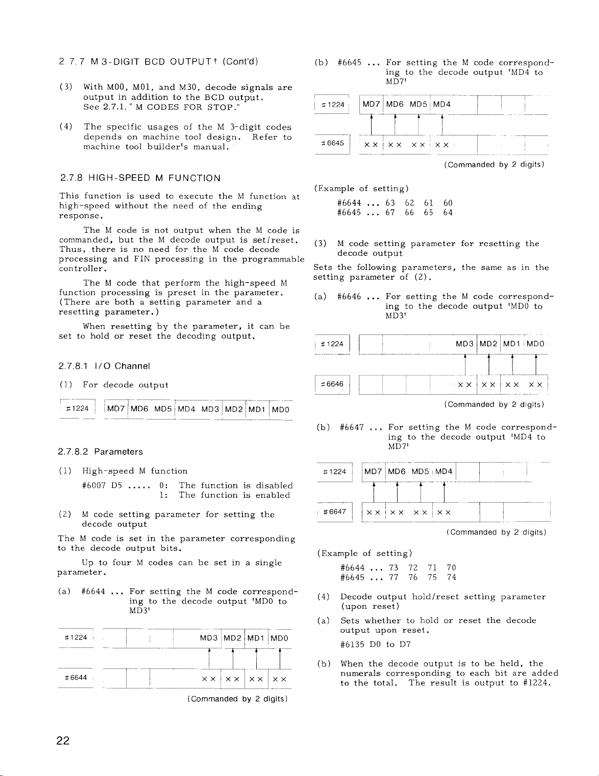
27
7 M 3-DIGIT BCD OUTPUTt (Cent’d)
With MOO, MO1, and M30, decode signals
(3)
output in addition to the BCD output.
See 2.7.1, “ M CODES FOR STOP. ”
The specific usages of the M 3-digit codes
(4)
depends on machine tool design. ‘Refer to
machine tool builder!s manual.
2.7.8 HIGH-SPEED M FUNCTION
This function is used to execute the M function at
high-speed without the need of the ending
response.
The M code is not output when the M code is
commanded, but the M decode output is setlreset.
Thus, there is no need for the M code decode
processing and
controller.
The M code that perform the high-speed M
function processing is preset in the parameter.
(There are both a setting parameter and a
resetting parameter. )
When resetting
set to hold or reset
2.7.8.1 1/0 Channel
(1) For decode output
~. -—_
F1224 ~
2.7.8.2 Parameters
FIN processing in the programmable
by the parameter, it
the decoding output.
:-”
IMD71MD6 MD51MD4 MD31MD2 MD1
——
‘-‘ 7-
are
can be
MDO
(b) #6645 . . .
r?
=1224
36645
‘1 :.~=x ;xm----
(Example of setting)
#6644 . . .
#6645 . . .
(3) M code setting parameter for resetting the
decode output
Sets the following parameters, the same as in the
setting parameter of (2),
(a) #6646 . . .
==1
For setting the M code corresponding to the decode output 1MD4 to
MD7’
MD7 MD6 MD51MD4 ~ ~ ~
n“
l-’-m-l ‘-- ‘ --
63 62 61 60
67 66 65 64
For setting the M code correspond-
ing to the decode output ‘MDO to
MD3’
!
1’
i;
–——
(Commanded by 2 digits)
MD3 MD2i MDl MDO
m-m
I
-T-–-–..
lxx~x;xx
FI rl- ~ ~“----xx
(Commanded by 2 digits)
(b) #6647 . . .
For setting the M code correspond-
ing to the decode output ‘MD4 to
MD7’
(1) High-speed M function
#6007D5 . . . . . 0:
M code setting parameter for setting the
(2)
decode output
The 1,4code is set in the parameter corresponding
to the decode output bits.
Up to four M codes can be set in a single
parameter.
(a) #6644 . . .
t!6644
For setting the M code correspond-
ing to the decode output ‘MDO to
MD3’
~- ”--~-” ~ ‘
The function is disabled
The function is enabled
1:
.xxxlx~
(Commanded by 2 digits)
22
=7 FD7”F===TT7”””i
#q , ~
(Example of setting)
(4)
(a)
(b)
xxix.
‘P- ,,..i
L ——
#6644 . . .
#6645
Decode output holdlreset setting parameter
Sets whether to hold or reset the decode
output upon reset.
#6135 DO to D7
When the decode output is to be held, the
numerals corresponding to each bit are added
to the total.
. . . 77
(upon reset)
Xx lxx
73 72 71 70
?6 75 74
The result is output to #1224.
._.—.——
1
--~ ---
(Commanded by 2 digits)
Page 31

MD1
MD7 MD61MD5
MD4 MD3
MD2
128 64 32 16 8 4 2 1
MDO
2.7.8.4 Example of High-speed M Function
Processing
The following are simple examples of the
high-speed M functions.
Value of each bit when the decode output
is to be held
(Exampje of setting)
{M~~ . . .
M . . .
{;$$ :::
JM67 . . .
Set MD1 output
Reset MD1 output
Set MD4 output
Reset MD4 output
Set MD7
OUtpUt
\M77 ... Reset MD7 outpUt
When the decode output is to be kept upon
reset, set the parameters as follows.
#6644 00006100
#6645 67000064
#6646 00007100
#6647 77000074
M code setting for setting
M code setting for resetting
The value of each bit corresponding to MD4
and MD7 are added to #6135,
16 + 128 = 144
144 is set in #6135.
(1) Sets the parameter (for setting, resetting).
#6644
#6645
#6646
#6647
(2) 01;
M60;
M61;
M62;
M63;
M64;
M65;
M67;
M30;
(3) 02;
M70;
M71;
M72;
M73;
M74;
M75;
M76 ;
h177;
M30:
63 62 61 60
67 66 65 64 setting
73 72 71 70
77 76 75 74
The left program is executed.
The bits corresponding to #1224 DO to
D7 are set.
M60 to M67 do not wait for FIN.
If an M code is to be held, set the total
of each bit corresponding to #6135.
The value to be held is set in #1224 at
the end of the program.
The left program is executed.
The bits corresponding to #1224 DO to
D7 are reset.
The M codes M70 to M71 do not wait for
FIN .
code setting for
M
M code setting for
resetting
#1224 is 1001000 upon reset.
2.7.8.3 Notes
Do not set the following hl codes when setting
(1)
the original M code.
.
MOO, MO1, M02, M30
When these M codes are set, the original M
code functions are lost;
has the priority.
.
M90 to M99
When these M codes are set, the M code
functions have the priority.
Check that the above-M codes are not found
when setting the M code.
(2) If an other process is waiting to be completed
in the same block, it waits for the first
process to be completed.
(3) Do not command two or more
same block.
* If executed, alarm occurs.
the high–speed M code
M codes in the
2.8 preparatory Functions (G-FuNcTlON)
2.8.1 LIST OF GCODES
Address G, plus up to 3 digits specify the meaning of the block. Table 2. 8.1 gives G codes and
their groups.
(1) G codes are broadly classified into the
following two types.
Meaning
Modal G-ccdeeffestive until the other
G-code G-cede of the same group is commanded.
Non-modal G-code effective only in the commanded
G-code
block.
(2) G codes in groups from 01 through 11 are
modal.
the power switch,
When the control is energized with
the G codes marked with
➤ in Table 2.8. 1 are automatically selected.
23
Page 32

1 LIST OF G CODES (Cent’d)
2.8.
(3)
G codes of * group in the Table 2.8.1 are
non–modal.
together with the other G codes in one
block .
(4)
The modal G codes can be commanded mixedly in a block.
(5)
G codes in Class B are basic, and those in
Class O are options. The use of optional
G codes is determined by the machine tool
design.
manual,
(6)
Standard G codes can be coverted to specialG codes I by parameters. This is a
basic feature, and, when parameter #6005D7
is set to 1, standard G codes are converted
to special G code 1.
(7)
When the sDecial G code IIowtion is incor-
porated in the control, the setting of param–
eter #6005D 7 to 1 will convert G codes to
special G codes D.
to O will reconvert the
ard G codes.
POSITIONING (G 00, G 06)
2.8.2
2.8.2.1 Positioning (G 00)
They should not be commanded
See the machine toolbuilder’s
.
Setting the parameter
G codes to the stand-
Along the axes specified by GOO, the ma-
(3)
chine slide moves in rapid traverse rates ,
independently of each other. The resultant
tool locus may not be a straight line, and
when working out the program , care must
be taken to avoid fouling between the tool
and the workpiece .
(4)
GOO is
When it is commanded, it remains effective
until other G codes in the 01 group are
commanded.
(5)
For the positioning with G 00, the pulse distribution is started only after the ERROR
DETECT state is turned on, and the program
advances to the next block only upon the
activation of the ERROR DETECT state after
the completion of the pulse distribution.
When this G code is used, therefore, the
workpiece edges are machined true, and
rounding is avoided.
(6)
Notes :
The ERROR DETECT ON state means the
a.
decrease of the servo lag pulses to the permissible level after the pulse distribution
for move command.
When T code is commanded, GOO should be
b,
put in the T-code block. GOO is required
for designation of tool traverse rate for
tool offset motion using T code.
a modal G code in the 01 group
(1) GOO X( U)... Z(W) . . . ;
This command moves a tool at rapid traverse
rate to the point (X, Z) in the coordinate
system set by the G50 command or moves it
away by (U, W) from the present point for
each axis independently.
(2) For the rapid traverse rate, as it depends
upon the machine,
builder’s manual.
EXAMPLE
X-Axis:
Z-Axis:
12 m/min
refer to the machine tool
6 m/min
z
EXAMPLE
G50 X150. Z1OO. ;
GOO TO1O1 S1OOO M03 ; . . .
. . . GOO for designation of traverse
rate for tool offset motion
(GOO) X30. Z5. ; . . . GOO can be omitted
in positioning.
E--l
P-’
-x
i
--
f’
i
5
30 DIA
[
1-
-.
~,
,/’
“1
/’
-z
Page 33

Table 2.8 List of G Codes
B: Basic
O: Optional
G Code
r
G 00
r
GO1
G 02
G 03
G 04
GC6
GIO
G 22
G
--+
G 27
G 28
G29
G30 Gm ~ G30
G31
23
Gscf~l
r
GOiI
r
—
GO1
G 02
G 03
G04 ~ GM
GOB
G 10
G 22
G 23
G 27
G28
G 29
G31 i
Special
G Code II
v
G#
v
GOI
G02 ~
G03 Gircular interpolation CCW, (radius R designation)
1
G06
GIO
G 22
G 23
G 27
G 28
G 29
I
G31
Group
01
*
—
01
—
* -=
%T=T%- O’
G35
G=
G 37
G38
~-.;:
—
G41
G 42
G43 G43
G44 G44
G%
G36
G 37
G28
G39 G
v
G40
G41
G 42 G 42
-.
G%
G36 Stored
G 37 Stored stroke limit 2nd area OFF o
G28
39 Stored stroke limit 3rd aea OFF
r
G40
G41
G43
G44 Tool radius compensation No. 4 0
*
07
06
06
Function
Positioning (rapid traverse feed) B
Linear interpolation, angle programming for linear interpolation B, O
Circular interpolation CW, (radius R designation) B, O
— .—
Dwel I B
ERROR DETECT OFF positioning B
Tool offset value setup
Radius programming for circular interpolation CW
Radius programming fm circular interpolation CCW
Automatic return to reference point
Retunrn to 2nd reference point
-~
tam= -~
Threadcutting, continuous threadcutting, multi-start threadcutting
Variable lead threadcutting
Tool set error compensation
stroke limit 2nd area ON o
Stored stroke limit 3rd area ON
Tool radius compsmsation cancel
~
—–
Tool radius compensation No. 1
I
Tool radius compensation No. 2 0
Tool radius ccfnpensation No. 3
_—
“~
Section
B, O
o
o
o
o
o
0
0
~ shows the G codes selectedwhen the control
is powered or reset.
Notes :
1.
The followingG codes for initialstatewhen
power is applied can be set by parameters.
Group G code Parameter
01 GOOor GOl
04 G980r G99
03
G900r G91 h6005 Do
#6005 DG
#?6005 DI
When the control is reset, whether G code
2.
of 01 group should be GOO or kept
as the
current one can be set by parameter #6005D6.
3.
Radius programming for circularinterpolation
can be made by G02 and G03 instead of G22
G23, respectively.
4.
Cornering can be programmed by GO1 instead
of Gll and G12.
5.
Initialstates of G codes of 05, 07, 08 groups
Refer to 2.8.7 Cornering.
when power is applied are determined by
their respective setting data (#6001D0, Dl,
D2).
25
Page 34

2.8 PREPARATORY FUNCTIONS (G-FUNCTION) (Cent’d)
Table 2.8 List of G Codes (Cent’d)
B: Basic
O: Optional
G Code ; ~s~~~ll
G 50
G 92 G 92
.—
G 51
G 65 G65 G65
G 72
G 73 G 73 G75 ; *
G 74
G 75 G 75
G 76
G90
G 92
G51
G 72 G 74
G 74 G76
G 76 G78
G 77 G 20
G78 I G21 ~ 01
I
Special
G Code
G,, t--
G 77
G93
G 91
G122
r
G123
Gill I Gill 1 Gill
GI12 T G712 ~ GI12 I *
G 122
r
G 123 G123 ;
G122 :
~ 11
.—
II
--* *
I
I
Group
~
Coordinate system setup
*
*
Maximum spindle revolution setup, work coordinate system setup
4— -—- -— -—--— -
i Return of current display value to origin
L -—..
User macro simple call
User macro modal call
User macro modal call cancel
Mirror image by programming ON
-—
L
Mirror image by programming OFF
Finishing cycle
Stock removal in turning
Stock removal in facing
Pattern repeating
Pack drilling in Z-axis
Grooving in X-axis
Automatic threadcutting cycle
Turning cycle A
Threading cycle
L
Facing cycle B
Constant surface speed control
Constant surface speed control cancel
Feed per minute (mm/min)
—
Feed per revolution (mm/rev)
—
Absolute command
03
Incremental command
Tool registration start
Tcml registration end
Ta~r multiple beveling/rounding o
Arc multiple beveling/rounding o
—.
Function Section
.
-——
—— .-—
Multiple repetitive cycies
--
.L -
]
Tool life control
7.
—4---B—
—-~ ----J—
-H..
.---c
–——-
.—. ..—
— .—
B
-—
0
~—
0
0
--0
0
I
0
0
0
0
0
I
B
&--–
o
+.— -—
B
o
0
~ showe the G codes selected when the control
is powered or reset.
Notes :
1. The following G codes for initial state when
power is applied can be set by parameters.
Group I
01 I GOOor G(X ~
041
03
G cede
G980r G99
G900r G91 i
Parameter
I
#6005
~6
ti6005 DI
46005 Do
2.
When the controlis reset, whether G code
of 01 group should be GOO or kept as the
current one can be set by parameter #6005D6.
3.
Radius programming for circularinterpolation
can be made by G02 and G03 insteaclof G22
G23, respectively.
4.
Cornering can be programmed by GOI instead
of Gll and G12. Refer to 2.8.7 Cornering.
5.
Initialstatesof G codes of 05, 07, 08 groups
when power is applied are determined by
theirrespective setting data (#6001D0, D1 ,
D2).
Page 35

2.8,2,2 Error Detect off Positioning (G06)
EXAMPLE
(1)
G06 x(u)””” ‘z(w).”- ;
With this command the positioning process
is identical to that of GOO except for the
following aspects.
G06 is a non-modal G code in the * group.
a.
It is effective only in the programmed block.
EXAMPLE
GOO X.. . Z.. . ;
G06 x.. . z,. . ; —
x.. . z.. . ; —
b.
With the positioning of G06, the positioning
Move by G06
Move by GOO
pulse dis~ribution &. immediately ‘started on the completion of the pulse distribution
for the preceding block, after making an
ERROR DETECT check, and the program
advances to the next block after the comple–
tion of the pulse distribution process. For
this reason, wrokpiece edges are rounded
to the extent of servo lag pulses.
Note :
The ERROR DETECT ON /OFF signals
(SMZ’) are effective only for cutting feeds, and
have no influence on the motion under GOO and
G06.
LINEAR INTERPOLATION (G 01) 1
2.8.3
‘GO1 X(U)””” Z(W).”. F(E). ”0 ;
A tool is moved to the point (X, Z ) on a straight
line at the traverse rate designated by the F or E
code in the coordinate system set by G50
moved away by (U, W) from the present point.
. F or E code must be specified in the block con-
taining the G 01 or in the previous block. If
not, i; causes a format error.
Feedrate designated by the F or E code is the tangential feedrate.
+,x
z
POSITION PROGRAMMED
1 /
\~
G50 X1OO. z60. ;
GOO T0202 s600 M03 ;
x35. Z5. ;
@ GO1 ZO F1. ;
Q
x60. FO.2 ;
+x
i
i
.
Angle programming for linear interpolation
----
/
/
Executed by
linear interpolation GO1.
/
/
With the control equipped with this option,
linear interpolation can be commanded at
specified angles.
GO1 X(U)””” A.. . F(E) . . . ;
or
GO1 Z(W)”. A.”. F(E) . . . ;
With these commands, a linear interpolation
will be executed by specifying angle A in
the + direction of the Z-axis and distance
either in X– or Z–axis direction. The feedrate in the tangential direction is specified
by the F or E code. The range of angle
specifiable with address A iS as fOllOWS.
% I programmable Range of Angle A
Metric Input
O- *360.0i)O0
Inch Input
I
(a)
(b)
u
I
2
PRESENT TOOI POSITION
+2
27
Page 36

2. 8.3 LINEAR INTERPOLATION (GO1) t (Cent’d)
Table 2.10
Table 2.9
Sign I
A+
A–
Angle counterclockwise from +Z-axis,
Angle clockwise from
+ Z-axis,
Meaning
A -
*
.A
+sr-
.rl-py-J-y&%
START
I
EXAMPLE
~ GO1 X50. A+150. FO.3 ;
~ GO1 zO. A–180. ;
POIN1
Meaning
Circular interpolation,
G 02
clockwise
-z
Circular interpolation,
G 03
counterclockwise
–Z
End point of arc on X-axis
x(u)
(Diameter value)
End point of arc on
z(w)
Z-axis
Distance fTom start wi nt of
I
arc to arc center on X-axis
(Radius value)
Distance from start point of
K
arc to arc-center on Z-axis
+x
.—
+.x EfQDPOINT
ii!=
.—
CENTER
.
‘.. -
~
. .
c)
z
~ CENTER
2
(;{1?
(;1)3
Iv
---
K
-z
START POINT
L
j
-z
50 DIP
F
I
7’Y-f+150”
)/
1 I
/
.
1
/--
-7
WJ--’ 60
2.8.4 CIRCULAR INTERPOLATION (G 02, G 03)
G02(G03) X( U)... Z(W) ... 1.. . K.. . F(E) ...;
A tool is moved on the circular arc whose center is away from the present position by (I, K) .
The end point of the arc is (X, Z) in the coordinate system set by G 50 or away from the
present position by (U, W)
A tool moves along a
verse rate specified by the F or E code.
The meanings of G02, G03 and each address
are shown below .
circular arc at the tra-
U-/
Fig, 2, 9
Circular interpolation of an arc on multiquadrant can be programmed in a single block.
EXAMPLE
.x
B
100 [11A
1~ ‘
60 DIA
.Z
Page 37

Table 2.11
Arc Center
Coordinate
I
K
The above case can be programmed as follows.
Gol z-. . F.. . ;
] G02 x60.
The feedrate commanded by the F code is a
tangential feedrate.
Notes :
The direction of the arc of G02 for Clockwise
1.
is defined as follows.
!!When viewing the X, Z plane in -Y direction
in the right–hand coordinate system, the tool
moves clockwise from the beginning point of
the arc.“
Therefore, the direction of rotation in the
plate (-X, Z plane) in the figure below is
presented inversely.
z-46.6 120. K-19.6 F.. . ; \
(10000, – 2700)
100 – 60
—=20mm
2
–
J2~2 – 202. ,;~
= –19.596+ –19.60 mm
Note that if the end point is designated in the
shaded area, the alarm is not displayed and the
tool will continue to move endlessly.
The end point coordinate should be precisely
commanded when the circular interpolation is
apphed to the tool nose radius compensation, or
the tool may not move properly. Generally, it
is recommendable to calculate up to the next
digit of least input increment and count fractions over 1/2 as one and disregard the rest.
3.
When the control is provided with Radius
Programming for Circular Interpolation, ra-
dius value can be commanded by G02, G03
instead of G22, G23.
EXAMPLE
G03 X80,0 Z15. O 1-10.0 K-30. O F150 ;
a.
x
END
I
‘a”aatl=?oo
15.00
I
55.00
I
z
-.
.
G 03
u
2. When the end point of arc is not designated
on the circumference specified by the radius,
the alarm is not displayed and the tool path
is as follows.
point of arc.
/
&
The mark o indicates the end
v
Y 42
*--
W/c
CENTER
o--
-0
/
P
b. G03 U40. O W-40. O 1-10.0 K-30. O F150 :
x
END
POINT
–40 {Jo
40.00
:,500
20.00
– 10.0(1
z
20.00
CENTER_~-
–30 lx)
15 0[1
&
2.8.5 DWELL (G 04)
(1) G04 U(P) . . . ;
This command interrupts feed for the length
of time designated by the address U or P.
(2) Dwell is programmed as an independent
block .
29
Page 38

2.8, 5 DWELL (G04) (Cent’d)
Table 2, 12
(3) The maximum length of time which can be
designated with address U or P is as fol-
lows .
Dwell time: 0.001 to 9999.99 seconds
Dwell time is not influenced by input/output
increment.
EXAMPLE :
G04 U3.5 ...
G04 P3500 . . .
Notes :
1.
G04 is a non–modal G code.
3. 5-second dwell
3. 5-second dwell
2. The counting of dwell time is started from
the instant the control enters the ERROR
DETECT ON state upon completion of the
move command block before G04.
Therefore, with G04 UO ; , the control
advances to the next block immediately
after detecting the ERROR DETECT ON
state.
EXAMPLE
GO1 W-1. F25 ;
G04 UO.2 ;
GO1 W-1. ;
With the above program, chip cutting feed
is obtained.
+x
— 1 mm feed
— O. 2 second dwell time
— 1 mm feed
Meaning
P For specifying tool offset No.
For changing the tcol offset value to the
x
z specified value.
For adding the specified value to the original
u
w tool offset values.
For changing the tool radius to the specified
R
vai ue.
The offset values for which no address is
programmed are not changed.
EXAMPLE
G1O P16 x32.5 wO.05 ;
-r T7————
~ 0.05 mm is added to
Z- axis value
LContents of tool offset No. 16
is changed
(2)
The above format is used to make offset
value tapes,
Offset M-emery at once.
The tape format is as follows .
/
Label
and to store the values in
\
I
02 DWELL
1mm
h
—.—
2. 8.6 TOOL OFFSET VALUE (G 10)+
With G 10 command,
set and corrected.
(1) G1O P-. . X(U). . Z(W) C.. R... ;
With this command, tool offset values are
set or corrected in part programs.
tool offset values can be
30
Q
0;
GIOP. .. X... Z.. .R . . . ;
GIOP. .. X... Z.. .R ... ;
GIO P... X.. . Z.. .R ... ;
~
/
~
Page 39

2.8.7 CORNERING (G 11, G @ ‘
(1) Beveling (Gil)
Gll
X( U)... K.. .
Z(W) . . . 1.. .
{
Gll X( U)... K.., F(E)... ;
END
+X
I
K *
POINT
1
Beveling for X-axis
K- K+
N
45”
m
START POINT
F(E) . . . ;
Ux
2
“ER)
(DIAMEI
Table 2.13
This command removes the sharp corner of
workpiece.
specified simultaneously in a block.
Meaning of each address is shown below.
Gll Z(W)... 1... F(E)... ;
END POINT
I+
I–
/
@7
Addresses X and Z cannot be
Beveling for Z-axis
,,50
POINT
START
w
I f
L
Bevellng Value
[
~ Bevellng Dlrecllon
Beveling values (K and I) are limited within
the following values.
The command exceeding the above value causes
format error.
GOO X30. ZO ;
~
@ I (Gil) x80. K-7. ; I
Gll Z-20. 18. F30 ;
I
7, 20.
DIA ‘~
O
8.
+x
lo
30 DIA
-z
I
Fig. 2.10
B
JZ
L-
(2) Rounding (G12)
This command performs the rounding of the
corner.
ified simultaneously in a block. The corner
is formed
each address is shown below.
Bevellng Value (Raalus Value)
—
Beve, ing Dlrectlon
Addresses X and Z cannot be spec -
ZLS a quarter–round.
Meaning of
31
Page 40

2. 8.7
CORNERING (Gil, G12)t (Cent’d)
Table 2.14
Rounding for X axis Rounding for Z axis
G12 X( U)... K.. . F(E). ., ;
K- K-
END
POINT >
-x
I
L.-...-.,
K’
L-,,”,,,,
T-_
\
m
START ~OINr
qcu~d,r,g c red w
u
~
,,!”.
x
[DIAMETER)
Rounding values ( K and I) are limited within Notes :
the following values.
1.
Gll and G12 are modal G codes in the A group .
They remain effective until other G codes in
]Kl <lU/21
The command exceeding the above value
causes format error.
GOO X20. ZO ;
, Ill<lwl
the group A are commanded.
2.
Gll and G12 are for one axis only. If they
are commanded for both axes in the same
block, they constitute a format error.
EXAMPLE
G12 X.. . W.. . K.. . ;
G12 Z(W)... K... F(E)... ;
END
POINT
1+
I–
z
/
iv
b
START
Po ,N?
K*
T___ ,Our,lr,g ,Ja,”e
T
Error “ 050”
: m
In the G 10 or G
3.
12 modes, no block without
I and K nor block in which I and K are O
can be commanded. If such a block is commanded, correct tool movement can not be
25.
I
.x
1
+7
6
.9-
I “
70 DIA
f
.-.
9
20 DIA
assured.
Tool radius compensation functional”is effec-
4.
tive to the blocks containing G 11 or G 12.
In the finish form commands G70 through G 73
5.
of the special canned cycle t, blocks contain–
ing Gll or G12 can be commanded.
6.
GO1 code can be used instead of Gll to specify identical beveling.
GO1
X( U)... K.. .
z(w) . . . 1$. .
I
7.
GO1 code can be used instead of G12 to speci-
fy rounding.
However, in this case, R must
I
F(E). . ;
J
be used instead of I and K.
Gol ~ X( U)... R... ‘ F(E)
Z(W) ... R, ..; ““” ;
i
32
Page 41

2.8.8 INCHIMETRIC DESIGNATION BY G CODE
(G 20, G 21)+
Unit of measurement (metric or inch) of input
data is selectively specified by the following G
codes.
b.
In principle,
tion when current position display (external) is useci.
The tool offset values are processed differ-
4.
ently in the G20 mode and the G21 mode.
G 20/G21 must be commanded after modifying
the tool offset values.
make the display reset opera–
These G codes are programmed at the leading
end of a block of its own.
are commanded, the units of all the following
motions are than ged.
Subsequent part programs
a.
Tool offset values
b.
part of settings and parameters
c.
Part of manual movements
d.
Displays
e.
Notes :
1. When G20 or G 21 is commanded, the setting
of inch/metric selection is changed.
fore, the state of G20/G21 at the time of
power application depends on the setting
by parameter #6001D0.
EXAMPLE
ER
CR
01234 ;
G20 ;
1
If these G codes
There-
Inch input designation
Stored Offset
Values (Inch)
15000
Processing in G 20 I Processing in G 21
4
1,5000 in.
I
15.000 mm
(Metric)
2,8.9 RADIUS PROGRAMMING FOR CIRCULAR iNTERPOLATION (G 22, G 23)+
In programming, circular interpolation (G02, G03) ,
the control requires the data of the arc-center
coordinates.
the addresses I and K.
(1) In programming of G2.2 or G23, the control
automatically calculates the arc center coor–
dinates (1 , K) from the radius value desig-
nated by the address R and performs circular
interpolation.
G22
( G23)
A tool moves along the circular arc whose
center is radius R away from the present
position. The end point of arc is at coor–
dinates (x,
the present position by (U, W) . Tool moves
along the circular arc at feedrate designated
by F code.
Normally, they are given by using
X( IJ) . . . Z(W) . . . R.. . F(E) . . . ;
1
Z) set by G50 or is away from
(2) The meanings of G22, G23 and each address
are shown below.
T
2.
When G 20 /G 21 selection is commanded in the
program, take the following procedure beforehand.
Cancel work coordinate system ( G50T ) , if
a.
used.
Cancel tool position offset, and tool radius
b.
compensation (G41 – G44) .
Take the following procedure after the com-
3.
mand of G20/G21 selection.
a. Program absolute zero point for all axes
before move command (G50) .
(3) Designaticm of radius value R
Radius value R is commanded by incremental
value with a sign of radius programming.
In this case,
When radius value R > 0, an arc, describing
less than 180°, and when R < 0, an arc
describin~; more than 180° are specified.
33
Page 42

2. 8.9 RADIUS PROGRAMMING FOR CIRCULAR
INTERPOLATION (G22, G23)t (Cent’d))
Table 2, 15
Meaning
.I
Circular interpolation by radius for
G 22
Cw
Circular interpolation by radius for
G 23
Ccw
x
\ ~(,z
...
G23
L!4_
-z
Notes :
1.
G22
and G23 codes are modal. ‘They are kept
until other G code of 01 group is commanded .
2.
In the
R is not contained or R is designated as zero
should not be commanded. Radius cannot be
designated by I and K .
3.
When R is varied with both start and end
points fixed , the tool willmove along the
following circular arc .
G22 or G23 mode, the block in which
The X-coordinate of the end of the i + ~
x (u)
arc (Diameter value)
I
The Z-coordinate of the end of the ~
=F-- “---:
Distance from the start point of arc ‘
R
‘-t
to arc center
(Incremental value with sign)
START
POINT
.- -
ARC
CENTER
\v
END
POINT
u
X2
z
R
START
POINT
—,
!
~
END POl’-
~
l:w.~po.
+
Fig. 2.11
&
I
Fig. 2.12
EXAMPLE
GO1 X40. Z-10. F20 ;
$, G02 I(X40. ) z-52.5 R30. (F20) ; ]
‘
--&7
z
Therefore, in the following case, the arc cen–
ter does not
(alarms “031,” “034”).
R < (Distance between start point and end point)
Tool nose radius compensation is effective
4.
for the block containing G22 or G23.
5.
The block containing G22 or 23 can be
designated in finishing shape commands of
special canned cycles (G70 to G73) .
6.
When the control is provided with radius pro-
gramming option , cir’cular interpolation by
radius (R) programming can be made by G02,
G03 instead of G22, G23.
2.8.10 REFERENCE POINT CHECK (G 27)
(1) G27 X(u) . . . Z(W) . . . ;
With this command, the tool is positioned to
the absolute coordinate point ( X , Z ) or incremental coordinate point (U, W) by moving
along the two axes simultaneously, and then,
the position is checked for conformance with
the reference point.
no command is given, positioning and check–
ing are not executed.
K:GIN
exist which causes data error
2
For the axis for which
END
POINT ,/’
ARC CENTER
/
/’
‘ R 3U
.Z
Fig, 2, 13
Page 43

(2) If the position is the reference point, the
return–to–reference lamp lights. The posi–
tion is the reference point in all the axial
directions specified, the automatic operation
is continued further.
the reference point even along one axis,
this constitutes the return-position–error,
and the automatic operation is interrupted.
(Cycle start lamp goes off. )
Notes :
The reference point is an fixed point on the
1.
machine tool to which the tool can return by
the motion under the control of the automatic
reference point return or G28 automatic ref–
erence point return function.
“Automatic Reference Point Return .“
2. If G27 is commanded in the tool position offset mode, the tool returns to the position
displaced from the reference point by the
tool offset value. Positioning cannot be made
at the reference point. Before commanding
G27, cancel the tool offset mode.
EXAMPLE
a.
Canceling tool offset in the block preceding G27.
TEIE]OO ;
G27 U.. . W.. . ;
b.
Canceling in the block containing G 27.
G27 U.. . W.. . TGT.; OO ;
The mirror image function is effective with the
3,
motion commanded by G27. To avoid the
return position error, command G 27 in the
G 69 mode ( Opposite tool post mirror image
off) .
AUTOMATIC RETURN TO REFERENCE POINT
2.8.11
(G 28)
(1) G28 X(U)””” z(w) . . . ;
With this command, the tool can be brought
back to the reference point automatically
after passing througkl an interim point. In
other words, the tool positions to the com-
manded absolute coordinate position (X , Z )
or incremental position (U, W) by moving
simultaneously along the two axes, and then
automatically returns to the reference point
by the reference point return function.
The specified point (X, Z) or (U, W) is
known as “INTERIM POSITIONING POINT ,“
or “INTERIivl POINT. “
If the position is not
See 6.2.1,
INTERIU POSITIONING POINT POINT
-x
,,AR:T’OYcd+---
POINT z
.-”
i’
\i”
z
REFERENCE
RETURN TO REFERENCE
x
— +Z
4+
Fig, 2.14
The tool does not move along the axis for
which instruction is omitted.
(2)
When the return to reference motion is com–
pleted, Reference Point Return lamp for the
returned axis lights. When the tool returns
to the reference point in both axes, the
automatic operation is resumed.
(3)
The series of RETURN TO REFERENCE
motions are as follows, With initialpower
application, the return motions to the
reference point are as shown below in the
low-speed mode as shown below.
APPROACH SPEED 1
,pEE,r-U::j::TER
SPEED REDUCTION LI!vIIT SVV
Fig, 2.15
Thereafter, the RETURN TO REFERENCE
POINT motion is in rapid traverse as under
the command of GOO.
RAPID TRAVERSE
I
Fig. 2.16
(4) However, when low traverse speed is speci–
fied by parameter #6010D 5 set to 1, the
same law motion speed as in the 1st time is
obtaineci.
I
REFERENCE
POINT
35
Page 44

2.8.11 AUTOMATIC RETURN TO REFERENCE
POINT (G28) (Cent’d)
Notes :
1. For parameter setting and other details of
the low traverse speed return motion shown
in Fig. 2.8.11.2, refer to 5.2.1 Manual Return to Reference Point.
2.
The starting point for RETURN TO REFERENCE POINT motion must be in the area
2.8.11.3 can
shown in Fig. 2.8.11.4.
Fig.
be started from any position.
RETURN
DIRECTION
(2)
When G.29 is used, consideration on the distance between points B and C is unnecessary
in programming.
tal instructions are used, this function is
useful to return the tool to the original co–
ordinate system after returning to the
reference zero.
Motions C + B and B + D are made simul-
(3)
taneously along the two axes in rapid traverse. However, the tool will not move in
the direction for which instruction is omitted.
(4)
Where G28 is programmed several times,
Especially when incremen-
the point B creat~d by the latest G28 in-
struction is effective for the motion by G 29.
~ “’s
3. Before writing G28 in the program, cancel
the tool position offset as shown below .
a. Canceling in the preceding block
TU 1100 ;
G28 X.. . Z.. . :
b. Canceling in the block containg G28
G28 X.. . Z.. . TE~OO ;
4.
When G 28 is written with the tool position
offset or tool radius compensation on, the
offset or compensation is automatically cancelled.
2,8.12 RETURN FROM REFERENCE POINT (G 29)
(1) With this function, the tool is positioned to
a specified point via the interim point, after
it has been once returned to the reference
zero point by the AUTOMATIC RETURN TO
REFERENCE ZERO COMMAND (G28) .
EXAMPLE (absolute input)
Coordinates of interim
these two blocks.
N20 G28 X1O. z20.
N25 G28 x30. ; —
N26 G29 x-40. z-50. ;
I
GOO X30. Z20.
u
point is equivalent to
;—G. 20. )
(30. 20. )
l--r
I I
‘+--
GOO X-40. Z-50. ;
Notes :
Commanding G 29 without the execution of
1.
G28 after turning on the control constitutes
an error “059. “
2. In principle,
gramming G28 or G29. If they are programmed while offset is effective, the interim
point B will be offset, and the tool will pass
point B’.
cancel tool offset before pro-
‘z
G28 X.. . Z.. . : Point A-+B+C
—“
Point B
G29 X.. Z.. . ;
Point D
[REFERENCE ZERO POINT,
~
-&
i
.4’.4
(reference zero point)
Point C+B+D
RETURN TO
REFERENCE ZERO
INTERIL! POINT
Fig, 2.17
Page 45

3. Commanding G29 in the TOOL RADIUS COM-
PENSATION mode (G40 - G44) or in CANNED
CYCLES (G70 - G76, G90, G92 and G94) constitutes an error.
EXAMPLE
N50 T0300 ;
N51 G28 u80. w20. ;
N52 T0400 ;
N53 G29 u-80. w40. ;
c (REFERENCE
ZERO POINT)
+
,/
/’
/
,0”
,/
-x
+Z
~L~l-
%--l
B /“
\
\
\
\\
\
\
\\
ID
40
2.8.13 2ND REFERENCE POINT RETURN (G 30)+
(1) G30 X( U)... Z(W) . . . ;
EXAMPL12
G30 U-40. W30 ;
T-],,,,/-~~E:
INTERIM POINT
TO 2N0 REFEPENCE
POINT
PARAMETER t 6613
Notes :
Before commanding G 30, after the energiza-
1.
tion of the control, G28 or MANUAL RETURN
TO REFERENCE POINT must be executed.
2.
For the 2rld REFERENCE POINT RETURN
motion, there is no area from where returning is impossible ,
and the tool can be return
from any position.
3.
The same notes 3.
and 4. of (5) for 2.8.11
Automatic Return to Reference Point apply
to G30 command.
4. When G29 is commanded after G 30, the tool
moves via the interim point specified by G30
to the position specified by G 29. However,
the interim point is renewed only in the axis
specified by G30.
POINT
With this command, the tool first moves to
an interim positioning point (X, Z) or (U,
W) in two axial directions simultaneously,
and then, moves to the 2nd reference point.
The tool does not move along the axis for
which no coordinate position is specified.
z
INTERIM
POINT
! +
/
/
2ND REFERENCE
POINT
Fig. 2.18
(2) The 2nd reference point is specified in
advance in terms of the distance from the
1st reference point commanded by G28, by
parameters #6612 and #6613.
2.8.14 SKIP FUNCTION (G 31)+
(1)
(2)
a.
X( U)... Z(W) . . . (F(E)...);
G31
With this command, a special linear inter–
polation is executed. During the interpolation movement under this instruction, the
tool interrupts the interpolation motion
immediately, and proceeds to the next block,
when a skip signal is received.
The motion after the receipt of a skip signal
varies with the instruction of the next
block.
When the next block is programmed in incremental values :
The tool moves incrementally in accordance
with the next block from the point where
the interpolation is interrupted.
37
Page 46

2, 8.14 SKIP FUNCTION (G31)t (Cent’d)
EXAMPLE
G31 W120. ;
GO1 u1OO. ;
ACTUAL
MOTION
x
~z
b.
When the next block is programmed in absolute values only for one axis:
The tool moves to the specified coordinate
position in the specified axis. It remains
at the position where the skip signal is re–
ceived, if axis is not specified.
EXAMPLE
G31 Z400. ;
GO1 X1OO. ;
,-+ :J
1~~
SKIP
SIGNAL ON
ACTUAL
x
L-
MOTION
z
4’
SKIP SIGNAL ON
/
COMMAND 1
.— --
4
COMMAND ~
~ 100 DIA
--—-
400
--l
G31 is a non-modal G code.
(3)
When no skip signal is received during the
execution of the block containing G 31, the
tool stops at the end of the block, and alarm
“087” is displayed.
(4)
The feedrate for blocks containing G 31 are
set in the following two methods, selectively
,50
I
v
specified by parameter #6019D 4.
a.
Designation by F in the same way as with
normal programs .
Presetting of feedrates by parameter #6232.
b
(5)
When a skip signal is received, the coordinate
values at that moment are automatically stored
as parameter data.
#6568 for storing X coordinate value
#656 9 for storing Z coordinate value
These data can be used as system’ variables
in user macros.
Notes :
1.
When parameter #6004D0 is set to 1, the pro-
gram is advanced to the next block automatically even when no skip signal. is received
during the execution of the block of G31.
2.
Before programming G31, be sure to program
G40 for canceling TOOL RADIUS COMPENSATION .
alarm “024. “
3.
Commanding G31 with skip signal ON advances
the program to the next ~loc~ without executing
the current block.
Failure to do this initiates
When the next block is programmed in abso-
c.
lute values along two axes :
The tool moves to the commanded position
from the point at which a skip signal is
received.
EXAMPLE
G31 W1OO.
GO1 X300.
Z200. ;
x
L
200.
2
I
L
/
SKIP SIGNAL ON
___
\
\
\
100
\ 300 DIP
\
\
2.8.15 THREAD CUTTING, CONTINUOUS THREAD
CUTTING (G 32)
This function is for cutting straight threads,
taper threads, scrolls and for continuous thread–
ing.
(1) G32 X( U)... Z(W) . . . F(E) . . . ;
With this command, the tool cuts threads up
to the point (X, Z ) specified in absolute
coordinates or (U, W) specified in incre–
mental coordinate values, at a lead desig–
nated by F or E code.
(2) The range of leads to be specified by F and
E codes is as follows.
Page 47

Table 2.16
Metric
Input
Metric
output
Inch
Input
Metric
Input
Inch
output
inch
Input
F code is for normal thread cutting.
E code is for precise thread cutting.
=
F24 I
E 26
F 32
E34 I EO.0303-E1270.0000mm
F24 \ FO.COl-F50.0000in.
E 26
FO,CxJOl–F19.6850 in.
I
E 0,~0004-E19.685000 in.
FO.01 -F 1270.00 mm
I
EO.O3OO1O-F5O.OOCOOO in.
Feedrates are limited by spindle-speed S as
follows.
Metric Output I F(E,XS<= 24,000 mm/min
inch Output F(E)x S S 2,400 in./min
The upper limit of X-axis speed component is
half the above.
(4) Command format of threadcutting is shown
below.
Table 2.17
Type
Straight
Thread
R~
I
Command format
(3) The direction of lead specified by F and E
codes is shown below.
Direction of Lead
Limitation of Taper Angle
+x
(x,z)
o
L~
+2
+x
I
~~~~
0> 45”
---------
cI
I
I
Fig. 2.19
END POINT
Direction of Lead
I
Lead in the direction of Z-axis
Lead in the direction of X-axis
Y
/
START PO IN
L [Lead)
“dI=*
EXAMPLE : Straight Thread
Thread leac[ L = 5.0 mm
6~=5. Omm
tiz=3. Omm
Cutting depth = 1.0 mm
(iJ GO(I
@ G32
+Z
T
GOO
G32
GOO
–x
u--42. ;
w--68. F5. O
IJ,Q. ;
w 68. ;
u-44. ;
w--68. ;
U44. ;
.-— ——
_12-
(’
I
+2
Page 48

2.8.15 THREAD CUTTING, CONTINUOUS
f-------~
THREAD CUTTING (G 32) (Cent’d)
EXAMPLE : Taper Thread
Thread lead L = 4.0 mm
51=3. Omm
62=2. Omm
Cutting depth = 1.0 mm
e
1.
(b) Worm Screw
GOO X13. ;
G32 x38. W-35. F4.
GOO x60. ;
W35. ;
X-n. ;
G32 X36. w-35. ;
GOO x60. ;
I
I
I
Continuous thread cutting
G32 X( U)... Z(W) . . . F(E) . . . ;
(G32) X( U)... Z(W). ;
(G32) X(U)”” Z(W)”. ;
This command executes thread cutting.
I
o;
I
I
I
Since the stop time between thread cutting
blocks is approximately zero, smooth, continuous thread cutting is possible. If
thread lead specification is changed midway,
the thread becomes irregular near the
boundary of blocks.
Notes :
1.
Allowances 6 1 and 6 z are required for thread
cutting because lead error occurs near the
starting and end points.
+x
v
I
(.
2.
If spindle speed is not constant during thread
cutting, the leads become incorrect due to the
servo lag.
Threading up for thread is not effective at
3.
G32.
commanded.
4.
5.
6.
Do not command M code for continuous thread
7,
tinuous thread cutting.
If necessary, G92 (or G76t) should be
The following operation is disregarded during thread cutting including G 32
. Feedrate Override
o Feed Hold Operation
. Single Block Operation
The G 32 command should not be commanded
in G98 mode.
In Dry Run mode, the tool moves at Jog feed-
rate.
cutting.
stops as feedhold and will not permit con-
If commanded, the commanded block
i
& ‘!
—
—
0.0 Regarded as 100%
— .Z
(a)
Pipe Joint
Page 49

(6) Allowance for lead error( 61, 6 2)
+x
1
tJ- #--
—
+Z
i
Fig. 2.20
61 and 6 z are obtained approximately from the
following equation.
Table 2.18
Equation
L (mm): Lead of thread
S(r/min): Spindle speed
K: Constent
(Normal value: 33)
a ( –): Accuracy of thread
_ AL. Lead error
—
1-
In: Natural logarithm
(Icg e)
2.8.16
With
two or more threads per lead can be machined
without shifting the starting point. In thread
cutting, the tool feed is started in phase with a
start point pulse ( 1 pulse /revolution) generated
by a pulse generator installed on the spindle to
control the starting point of thread always at the
same position around the workpiece circumference.
after cutting a thread by controlling the starting
point by the starting point pulse, another thread
is cut by starting the cutting feed at an angular
position of the spindle which is displaced from
the starting pulse position by a preset angle.
MULTI -S,TART THREAD CUTTING (G 32)’
this function, multi–start threads containing
With the multi-start thread cutting function,
LEAD
m
a
(ln~ – 1)
EXAMPLE
1150 1/100
2.91 3.61
Lead of thread L = 3.0 mm
Spindle speed
Thread cutting a = 1/100
61>
_3. ox 500
—
60.K
~=
62>
60. K
1/150 1/200
4.01
S = 500 rjrnin
x3.61 =3. Omm
3.0X500 =0 p,qmm
60. K “
1/250 1/300
4.29 ; 4.52
4.70
Two Start Thread
Fig. 2.21
(1)
G32 X((J) . . . Z(W) . . . F(E) . . . B.. . ;
With this command, the tool cuts a thread
starting at an angular position which is
displaced from the position corresponding
to the starting pulse by an angle specified
by B, to X(U) or Z(W) point, at a lead
specified by F Or E code.
(2)
The data specified by address B in the
multi–start thread cutting function is
as follows.
Least input increment: O. 001 deg.
Programmable range: O s B s 360.000
When decimal point input is used, B 1.=ldeg.
The B code is non-modal, and is effective
only in the programmed block.
41
Page 50

2.8.16 MULTI-START
THREAD CUTTING (G32) t
(Cent’d)
(3) Number of starts
In principle, the
the workpiece circumference sh&jd divide
the circumference into equal portions.
and B code
thread starting points on
EXAMPLE
G32 W“”.
G32 W.”’
B90
Continuous
ting cannot
thread cut-
be performed
because of feedhold at
this block.
EXAMPLE : Two-start Thread
2START THREAD
START:NG POINT
@&@
1S- n-READ NO 8
21,: ‘1PEA2 E180
CO MtJAh D
3-START TbREACI
STARTING PO NT
1ST ‘H REAC
2ND THRE/t2 6’20
3RD T}it?EA3 E240
NC e 1ST T-IREAD hO B
c c 1.1b>’-.h 2
Fig. 2, 22
4-START THREAD
STARTING POINT
2N0 TH5EAD B90
3 R13THREAD 3180
4 T+ THREAD B270
COMI.lANG
Notes :
1. Since the angular position detection pulses
(4096 pulses/rev. ) generated from the spin-
dle pulse generator is used to define the
angular position of the spindle with respect
to the starting point as controlled by the B
command, the least detectable increment is
360°/4096 pulses ~, O. 08790/pulse.
From the position commanded by B codes,
an error up to fl pulse may occur.
2. The angular position from the starting pulse
can be specified in both forward and reverse
directions by BO - B 360. commands.
When B command is made to specify angles
3.
outside the permissible range (O - 360.000) ,
alarm “062” is displayed,
If multi-start thread cutting B is speci-
fied, continuous thread cutting cannot be
executed.
GOO U.. . ;
G32 W.. . F.-.
GOO U.. . ;
w.. . ;
u.. . ;
G32 W.. . ;
GOO U.. . ;
G32 W.. . B180
GOO U.. . ;
w.. . ;
u“”” ;
G32 W.. . B180. ;
1
~ Threading of part I@)
1
Page 51

2.8.17 VARIABLE LEAD THREAD CUTTING+
G34 X( U)... z(w) . . . K.. F(E) -$” ;
(1)
With this command, variable lead screws are
controlled with the increase or decrease of
lead per revolution specified by address K.
VARIABLE LEAD SCREW
Fig. 2.23
Variable Lead Threadcutting
(3) Confirmation calculation for K command of
variable lead thread cutting.
a. K command is restricted in the following
conditions.
Feedrate at end point must not exceed
(i)
programmable range.
500 mrfl/rev (metric output) or 50 in
rev (inch output)
(ii)
Feedrate at end point must not be minus
value.
(iii)
Accumulated value of movement due to
lead variation must not exceed 4194.303
mm (metric output) or 419.4303 in (inch
output) .
(iv)
Feedrate change corres~ondin~ to lead
variation must not exceed 5, 400 mm /rein
(metric output) or 540 in /mm (inch output
The range of K programmable for variable
(2)
lead screws is as follows.
Least input increment:
0.0001 mm/rev.
(Metric Input)
0.000001 in./rev.
(Inch Input)
Programmable range:
The highest feedrate is within the maximum
a.
programmable feedrate range ( 500 mm/rev
(metric) or 50 in/rev. (inch))
The total displacement resulting from changes
b.
in lead is within the following.
4194.303 mm (metric output)
419.4303 in.
Feedrate change corresponding to lead
c.
(inch output)
variation must not exceed 5, 400 mm /rein
(metric output) or 540 inJmm (inch output).
Lead value should not be minus value.
d.
Notes :
When variable lead threads are cut by continu-
1.
ous block programs, command pulses are
interrupt ed at block junctions.
If K commands exceed the permissible range,
2.
alarm (1060!!” will be displayed.
When G 34 command is executed in the Dry
3.
Run mode, the tool moves only at the speed
specified by the manual continuous feedrate
command, if parameter SCRDRN ( #6019 BIT5)
is set to 1.
When parameter
4.
!11oIN!! ( #6006D5) is set to
1, least increment for K commands is 0.001
mm/rev or O. 0001 in./rev.
Commanding address B in G34 block causes
5.
alarm 11(360.II
b. The control checks the restriction described
above using the following equation.
F:
Fixed lead command (mm /rev or in,f
rev)
K:
Variable lead command (mm/rev or
in./rev )
Distance between start and end points
w:
on Z–axis (mm or inch) .
For facing screw, distance is specified
as U on X-axis.
Spindle speed (rev/rein)
s:
Spindle speed for movement between
N:
start and end points (rev)
-(F +$) + (F +*)2 +2. K.W
N=
i
K
Equaticm for limit in a. (i)
(i)
F + ~ + KN S 500.000 mm/rev or
50.0000 in/rev
Equaticm for limit in a. (ii)
(ii)
(F+~-)2+2Kw>I)
(iii)
Equaticm for limit in a. (iii)
~KN2 S 4194, 303 mm or
419,4303 in
Equaticln for limit in a. (iv)
(iv)
. K.N S 5,400 mm/min or 540 in/rein
&
43
Page 52

2.8.18 STORED STROKE LIMIT (G 36-G 39)+
This function is for preventing the entry of the
tool into the prohibited area, in both automatic
operation mode and manual operation mode, to
secure safer operation.
hibited areas can be set up as shown below.
2ND PROHIBITED AREA,
(BY G36)
I /
/
INSIDE OR
OUTSIDE
PROHIBITION
c1
I)
-x
I
4+---‘z
Setting 1st prohibited area
(1)
Set + side boundary A and - side boundary
a.
B by parameter.
The area outside the range between points
b.
B is prohibited.
This area can not be specified by part
c.
programs.
(2)
Setting 2nd prohibited area
Set + side boundary C and - side boundary
a.
D by the setting function.
Selectively designate the inside or the out-
b.
side of the area between points C and E by
parameter #6007D0.
Three types of pro–
1ST PROHIBITED AREA
(BY PARAMETER)
OLTSIDE PROHIBITION
c
INSIDE OR OUTSIDE PROHIBITION
~
P
3RD PROHIBITED
AREA (BY G 38)
Fig. 2.25
E
G36 U.. . W.. 1.. . K.. . ;
z=
coordinate coordinate
The area check function is turned off by a
single code block G37 ; .
Setting 3rd prohibited area
(3)
Set up + side boundary point E and - side
a.
boundary point F by the setting function.
.4
A
Selectively designate the inside or the out-
b.
side of the area between points E and F by
parameter #6007D 1.
=
In addition to the method by the s’etting
c.
function, the following instruction can be
used to set a prohibited area, and to turn
on the area check function also.
G38 U.. . W.. 1.. . K.. . ;
Y--r-
Point E
coordinate coordinate
The area check function is turned off by a
single code block G39 ; .
Point F
Table 2.19 Parameters and Settings for
Setting Prohibited Area
\
Ist
Prohibited
Area
Point A z 66m
Point B
X axis
~%06
Z axis
z 66m
8&137
Division
—
Parameter
=
In addition to the method by the setting
c.
function, the following instruction can be
used to set a prohibited area, and to turn
on the area check function also.
44
(4)
Coordinate system for area setting
The above Points A through G are all set in
absolute values on the machine coordinate
system (MACHINE) .
is written as the distance from the ( lst)
reference point ( 1 = least output (move) increment) .
become effective unless the manual or automatic RETURN TO REFERENCE ZERO is ex–
ecuted once after the energization of the
control.
Therefore, this function will not
That is, the position
Page 53

(5) Effective-ineffective selection of prohibited
are a
With the following setting, the 2nd and the
3rd prohibited areas are selectively made
effective and ineffective.
c
Setting
~6001 DI
When G36 through G39 are commanded, these
setting data are automatically rewritten.
Therefore, the ON or OFF state ultimately
specified by G code commands or setting
function becomes effective.
hibited area is always in the CHECK ON
mode.
(6) Starting area check
When the tool is returned to the reference
point once manually or automatically after
the energization of the control, the area
check function is started immediately.
Therefore, if the reference point is in the
prohibited area, immediately, STROKE
LIMIT ERROR will be caused. In
this case, turn off the area check function,
and change the data.
(7) Stored stroke limit error
the tool enters the prohibited area,
When
it stops just inside the boundary line, and
the control enters STORED STROKE LIMIT
ERROR state.
only be moved manually in the return direc-
tion.
I
2nd prohibited area check OFF
o
1
2nd prohibited area check ON
0
3rd prohibited area check
1
3rd prohibited area check ON
In this case, the tool can
Meaning
The 1st pro-
OFF
EXAMPLE
1STPROHI131TEDAREA
B . D (-11000, -100’00)
Inside/Outside
F
i:DAREA(NISIDE)
10,-8000)
E(-4000 6500)
3RDPROHIBITEDAREA(INSIDE)
ir
7000, -9000)
7-///////// /// ////////// /
— <_. WORKPIECE
Table 2.20
Pararnetar/
Setting
~6007 DO
a6007 D,
~65rXI
6501
+
=s
:6502 ~ –11000
#6503
+x
1
I
/
/
/
/
/
/
/
/
/
/h.
Contents
–
–6000
–10000
A (2003, 10CO) )
+Z
REFERENCE
POINT
CENTER
o
o
5000
c
)
Displaying remaining distance
(8
With this function, the distance between the
current tool position and the boundary of the
prohibited area in the X and Z directions
are displayed on the CRT . Refer to 4.3.4.6.
“ Stored Stroke Limit .“
Notes :
The points on the boundary line in both
1.
axes are included in the prohibited area.
2. Two prohibited areas can be set with partial
overlapping.
In the MACHINE LOCK ON mode, AREA
3.
CHECK function is not effective.
Third Area
First Area
~L
e;
#e601
?6606
+6607
1000
–11000
–ICQOO
B
“)
45
Page 54

2 8.19 TOOL NOSE RADIUS COMPENSATION
(G 40 THROUGH G 44)
VIRTJAL
TIP NOSE
Because
a deviation between the desired curve and the
actual curve produced.
are not enough for taper and circular cuttings.
The tool nose radius compensation option resolves
the problem of nose radius.
(1)
a.
of a nose radius of lathe tools, there is
Therefore, tool offsets
See Fig. 2.26.
m—- -+
CENTER
PROGRAtiMED CIJTTING CONTOUR,
WITH TOOL NOSE RADIUS
COMPENSATION
Fig. 2.26
Tool
nose radius values
Radius value storage
Tool nose radius value must be written in the
storage before the tool nose radius compensation is commanded.
can be written in the storage depends upon
the machine.
T 3-digit: 9 sets
T 4-digit:
Refer to 2.6.2, “
16 or 50 sets
Tool Offset Memory+ .“
j ‘TOOL NOSER
\
VIRTUAL
TOOL NOSE
Number of pairs that
ALL ROUND
INSERT
Fig. 2.27
For the writing
nose radius compensation, refer to Fig .
4.3.5 Displaying and Writing Tool Offset
Data.
(2) T code designation
The T code for tool nose radius compensation
a.
must be programmed with sign (+ or -) .
The address character is R .
of radius values for tool
T f ~n ~’~ (In the case of T 4-digit)
l--T-l-
1-
Offset number for tool position
offset and tool nose radius
compensation
L
~ Direction of tool nose radius
ll+l! . . .
rl_ll . . .
Right side viewed in the direction
of tool travel
Left side viewed in the direction
of tool travel
““1’-“
Tool number
compensation
..,1. ,,
b.
Range of tool nose radius values
Radius value can be set within the following
range.
Metric
Inch
i
o *99.999 I o *9.9999
c. Setting of tool nose radius values
Radius value of tool nose must be set with-
out signs.
‘x-lfiii24iiL
Fig. 2.28
b . When a tool is used for turning and for fac-
ing , as the direction of tool motion changes ,
the correct direction of compensation should
be programmed with sign of T code .
q,~~.
,X
—
*
Fig. 2.29
s,~~
CO!b)PEhSATION (T ~ ‘
LEFT SIDE
COMPENSATION T
—-z
Page 55

The direction of compensation is changed
from + to – or - to + during program execution.
be necessarily programmed to cancel the
tool nose radius compensation.
(3)
G code designation (G40 to G44)
a.
G code of tool nose radius compensation
One of G41, G42, G43 and G44 and T code
should be programmed before the execution
of tool nose radius compensation.
tween the virtual tool nose and the tool
center.
G40 or T~ U 00 command should not
(G41 to G44)
four G codes specify the relationship be-
These
(ii)
When the power supply is turned on, G40
is in effect.
(iii) When the RESET button is depressed, G
code of 06 group are cancelled and G40
becomes effective.
(4) Tool motion on the tool nose radius compen-
sation
2.31. shows the outline of the tool
Fig.
a.
motion .
...
..>
-Ku2)’-
VIRTUAL
TOOL TIPS
t
t
R
Q>l
G 43
Regardless of the mode of tool nose radius
compensation, the current position of the
virtual tool nose is displayed by depress–
ing the POS pushbutton.
b. Issue G40 to cancel the tool nose radius com-
pensation.
c. Cautions in programming G code
(i)
Since G40 to G44 are modal G codes of
06 group, they are retained until the
other G code is commanded. Before
switching one of G41, G42, G43 and G44
to another, G40 must be intermediated to
cancel the compensation.
\
TOOL
CENTER
G 42
El
‘ G~~
Fig. 2.30
\
L=-
G41
c1
/
v +’
G ‘NJ
n]
// \\
G 43
c1
G 44
c1
-Z
BLOCK OF
+x
(iii)
(iv)
Relationship between tool nose radius com-
b,
pensaticm and tool position offset
Tool nose radius compensation apply to
the programmed contour which has been
offset by the tool position offset function.
~,
‘:3;,
Fig. 2,31
When the compensation is cancelled, the
programmed contour meets with the path
of virtual tool tip ( @ and @) .
In compensation mode, the tool center
path is deviated by radius from the pro-
grammed contour.
of virtual tool nose does not meet with
programmed contour. But the current
position displayed by depressing POS
ke is the position of virtual tool tip
( bto @).
The (connection between two blocks in
compensation mode is provided by the
intersection of tool center paths (M97)
and I:)y the circular arc (M96) . In the
above diagram,
nected by a circular arc.
Block @ for compensation start and
block @ for compensation cancel per-
form the connection of compensation
mode and compensation cancel mode.
Program should be made carefully for
these blocks.
Therefore, the path
blocks 3 and 4 are con-
COMPENSATIOh
WITH G 00
47
Page 56

2 8.19 TOOL NOSE RADIUS COMPENSATION
(G40 THROUGH G 44) (Cent’d)
HOW to enter compensation mode
(5)
a. Compensation mode is set when both the tool
offset number by T code and G41 (or G42
through G44) are instructed. When this
mode is set, tool nose radius compensation is
started. More precisely, compensation mode
is entered when the AND condition between
T code and G code is established. Hence,
the order in which these codes are specified
does not affect the operation.
(b)
~) GOO T+0202 ;
@ GO1 G41 x20. z7. F600 ;
@ G02 U30. W-15. 115 FO.2 ;
Compensation Mode
Movement at Start
of Compensation
7
(for GO1)
b. At the start of compensation. the tool center
is offset onto the n~rmal of the origin of the
block G41 to G 44 which entered the compensation mode first or of the block immediately
after T code.
right of tool advancing direction when T +
is specified and to the left when T– is specified.
Sample Program (A) :
(a)
~
GOO T+ O1O1 ;
(2J GOO G41 X30. Z5.
,-,
3‘UGO1 z-18. FO.25 ;
Compensation Mode
The offset is made to the
Movement at
Start of Compen sation ( for GOO)
[
;J
-x
CEhTEP
DIA
x
3
G U1
.
h
I
-z
-
c. If the block of G41 (or G42 through G44)
satisfying the compensation mode condition
does not have the move command, the compensation starts and the tool center is moved
on the normal.
Since G41 (or G42 through G44) involves
such a movement, it is necessary to specify
GOO or GO1 in th last or current block for
the G code of 01 group. Specification of a
G code other than GOO, GO1, and Gll will
result in alarm “026. “
EXAMPLE (B) :
has no move command.
(c)
l@
GOO T+0303 ;
g
GO1 G41 F.. . ;
(3’ GO1 X.. . Z.. . F.. . ;
G41 (or G42 through G44)
48
Page 57

(d)
@ GOO T-0404 ;
GO1 G44 F.. . ;
@
@ G03 X.. . Z.. . 1.. F.. ! ;
m
Note that the
normal to the
diately after G41 (or G 42 through G44) or
T code, for each of above examples (a)
through (b) .
block or the block following T code has no
move command, one block ahead is read and
the compensation start operation is performed
on that block.
fied, up to two blocks may be programmed
consecutively.
blocks have no move command, an error is
caused.
(6) Movement in compensation mode
When the tool nose radius compensation mode
is entered by G 41 (or G 42 through G44) command, the tool center keeps moving along
the path which has been offset by the tool
nose radius by the program command, until
the mode is cancelled by G40 or T •l 000
command.
lated by the control.
tour may be specified in the part program.
However, the following should be considered
for the inter-block movements and special
contours:
I
CENTER
tool center is offset onto the
start point of the block imme-
If G41 (or G42 through G44)
With no move command speci-
However, if three or more
The path is automatically calcu-
G44
So, only the cut con-
For an outside corner (tangent-line angle
(ii)
is more than 180°) , the movement is controlled.by the following M-code commands:
M96 ...
M97 ...
Tool radius compensation
circular path ON
Tool radius compensation
circular path OFF
(execution of intersection
calculation)
/
\
\/\\
‘.,
\
.
m
M96: Circular Path Mode
M97: Intersection Computing Mode
Movement of circular path is included in
the previous block.
Normally, M96 is used for this operation
However, when there is a possibility of
an “overcut” in cutting special shapes
with the M96, M97 should be used.
b,
Movement in GOO mode
The instruction G 00 positions tools independ-
ently alc,ng each axis toward the final offset
position,. Care should be taken on the cutter
path so that tool does not contact the work.
TOOL MC VEMENT
Inter-block movement
a.
For an inside corner (tangent-line angle
(i)
is less than 180°) , the intersection point
is computed and is passed.
point computing formula.
v
PASSING INTERSECTION
POINT
(Intersection
GOO OR
G 01
Fig. 2.32
PROGRAMMED
COMMAND
49
Page 58

2.8.19 TOOL NOSE RADIUS COMPENSATION
THROUGH G 44)+ (Cent’d )
(G 40
Movement in compensation mode (Cent’d)
(6)
Programming consideration in compensation
c.
mode
(i) Be careful not to program a
shaped cutting contour.
T–
(a) Wrong
M 96
‘IY.---”~---” ------- ~;;::oo,
-=:: --.–_.:,___________
Q-
INTERSECTION IS FAR AWAY
4“
T-
f ;l&cJp,4::
i
(b) Correct
wedge-
NOSE OF
GET IN
Command involving no movement in compen-
d.
sation mode
The control normally reads two blocks ahead
during tool radius compensation mode and
calculates the tcml path. If either of these
blocks gives no coordinate instructions such
as G04 (dwell) , the control reads a block
further ahead and makes calculations. When
coordinate instructions are missing in three
or more blocks , tool radius compensation be-
comes impossible and accurate tool path can–
not be obtained.
where G41 to G44 are used ensure that, after
them , two or more blocks without movement
command in the compensation plane will not
follow .
GO1 G41 F.. .
Therefore, in a program
;
T+
\l 97
(ii)
(a) Wrong
(b) Correct
-------
i-
L ---—-.
~
Program the tool movement so that the
tool nose of 2R diameter can be in the
contour,
; j
------
------
1
T
\f 97
_ PROGRAM IS MADE SO
THAT TOOL NOSE OF
1
2 R CAN GET IN THE
WENDGE
Q
PROGRAMMED CONTOUR
PROGRAMMED CONTOUR
G04 U.. . ;
M.. . ;
M40 ;
movement instruction is programmed
If no
Compensation is normally
made by the two or less
1
blocks without move command.
in three consecutive blocks ,tool center is
offset on the normal line at the end point
of the block immediate before them.
e.
Use of dummy blocks
If it is impossible to specify a move command
in three or more consecutive blocks and the
offset on the normal line is not satisfactory,
a dummy block may be inserted.
The dummy block does not cause an actual
movement.
purpose of providing the data necessary for
the tool nose radius computation. For the
address of this dummy command, I and K
are used.
I: X-axis dummy command (incremental) .
K : Z -axis dummy command (incremental) .
This block is specified for the
/
Page 59

EXAMPLE :
N1 GO1 G41 X.. . Z,.. F.. . ;
N2 X.. . z.. . ;
N5 2.. . ;
—
Three
blocks
or more
1
Dummy block
/
N6 1.. . K.. . ;
N7 fvfxx
N8 G04 U.”” ;
N9 MM
N1O X“”. z.. . ;
Nll Z“. . ;
11
Ii
I and K should be signed according to the
type of the circular arc.
,M96 CIRCULAR PATH MODE)
By dummy block N 11, the linear command
block of N 10 stops at point A for the follow-
ing circular movement.
f. Switching between T + and T - in compensation
mode
This coml?ensation provides the switching
between T + and T - without canceling the
compensation by G40
EXAMPLE:
or T 3P 00 command.
%0 5
‘x ~
Namely, specify incremental commands I and
K, which are equivalent
mand,
Remarks:
is a circular interpolation, generate the
linear dummy block that specifies the direc-
tion of the tangent line
the circular command.
EXAMPLE :
N1O GO1 Z“. . F.. . ;
IN1l GO1 1(-a) K(-b) ; I
N12
N13 MOO ;
N14 MM ;
rN15 G02 X... Z... 1...” K... ;I
N164. .
in N6 for the dummy block.
If the purpose of the dummy block
kfxx ;
CENTER
Nil DUMMY BLOCK
(LOQEAR LINE)
THREE BLOCKS OR
MORE INCLUDING
NO MOVE COMMAND
I
-b
to N 10 block com-
at the start point of
Dummy block
IN5 GOO -T+O1O1 ; ~
Designates righthand side
compen-
sation facing {he
N6 G41 X.. . Z.. . ;
N7 GO1 X.. . Z.. . F.. . ;
N8 x.. . ;
N9 T-O1O1 Z.. . F600 ;
r: 7::::~:eft-
N1O X.. > F.. . ; compensation
x
g . Modification of tool offset volume in compen-
proceeding direction
/ (M96 MODE)
sation mode
It is invalid to newly specify a tool offset
number by T
code in compensation mode.
The originally specified tool offset number
remains valid until the compensation mode
is cancelled by G40 or T G3 00 command.
51
Page 60

2.8.19 TOOL NOSE RADIUS COMPENSATION
(G40 THROUGH G44) (Cent’d)
Movement in compensation mode (Cent’d)
(6)
However,
changed by varying the offset memory con–
tents corresponding to the originally speci–
fied tool offset number, by means of MD I
operation.
tool offset number is made valid beginning
with the block newly stored in the prefetch
buffer.
the tool nose radius value may be
After this modification, the new
SINCE THE TOOL POSl TION OFFSET IS CANCELLE2 THE POSITION
IS (110 40) FOR THE
REFERENCE TOOL
,,’
/’
c ()[,
---::-----––=U \
—--+---”’
(b)
(;4!
\@
,,7, ,
(7) How to cancel compensation mode
a. When G40 or T q~ 00 is specified, compen-
sation mode is cancelled, terminating the
tool nose radius compensation operation.
.-
~i
%
*CJ
~-d .
~o
CLz .
g.
I._.
U G40 j-”--’i6iO; -; ‘--G~Oj-–iOlOo ;
TOlOO ;
Upon termination of compensation, the tool
b.
center is offset onto the normal line to the
end point of the finalblock in compensation
mode, or the block immediately before
that for which G40 or T 3700 has been
specified. (Consequently, if a retracting
which results in acute–angle contour is
specified in G40 or T 3E 00 block, no uncut
portion is produced. )
Then, the tool moves so that the virtual
tool nose matches the end point of the move
command specified in G40 or T all00 block.
EXAMPLE A :
(T+ O1O1, G41)
.~f
21.
z
1.
si?(~1
1
~ GOO G40 X11O. Z40. ; ~
G40 ;
(a)
MOTION ON COMPLE-
TION OF COl
(GOO)
GO1 U20. FO.25 ;
____
[PENS ATION
(T+0202, G41)
@
GO1 X.. . Z.. . F.. . ;
@ GO1 U24. FO.3 ;
MOTION ON COMPLETION OF COMPENSATION (GOO)
I
@ GO1 G40 x80. z40. F6. ;
@ GOO T+0200 ;
-1
—--+-’--z
If the block of G40 (Nose radius compen-
c.
sation cancel) does not have the mov-e com–
mand, the virtual tool nose moves to the
specified end point.
G40 (and T DU 00) commands contain movement.
Specify GOO or GO1 in the block previous to or
the same as G40.
other than GOO, GO1, or Gil, alarm II027!!will be
activated.
If the G code of 01 group is
IQ
TO1OO ;
Page 61

EXAMPLE B: Move command is not included
in G 40 block for canceling compensation.
(c)
(T-0303, G41)
@ GO1 X... Z... F... ;
‘~ GO1 G40 F... ;
GOO T-0300 ;
\
,5; , -
/’
,.’
/
P
(d)
(T+0404, G44)
G02 X.. . Z.. . K.. . F.. . ;
,~, MOVEMENT AT
~]
“ COMPENSATION
G41
START BY 2
Notes :
programmed shapes that produce input
a.
errors
When programming an inside arc with tool
(i)
compensation, if programmed arc radius R s
tool radius d
TOICL
—
-—-.
:>
R
62
r..
R
r~:$.?.L
r<d
—
-—.
7
—-—
r
--.,,
r
‘- )
Outside compensation is correctly
made even when r < R
1
I
GO1 G40 F.. . :
CENTER
MOVEMENT AT
I s:H%s8T’ON
I COMMAND
G44
is per-
GOO T+0400 ; ‘Z
cc
.-
,.,
/’
,’
/
–L_..-–_.i
m
Note that, for each of above examples (a)
through (b) , the tool center is temporarily
offset onto the normal line to the end point
of the block immediately before G04 or
T E200 command.
When tool nose radius compensation is can-
celled by the use of T’~E 00 command, the
tool position offset cancel operation
formed concurrently with the operation at
tool nose radius compensation termination.
The cancel operation provides the move-
ment in which the virtual tool nose matches
the last specified position for which tool
position offset has been cancelled. If co-
existence of these operations is not desired,
cancel either of them by the use of GAO
command.
(ii) When :no intersection point exists on the
locus lofthe offset tool center.
,--
/
-.
NO INTERSECTION
/’ ‘ 5,2:
\)< ,’ , I
NO INTERSECTION
-.
%
(a)
~
TOOL
\
&
(b)
R,
53
Page 62

2.8.19 TOOL NOSE RADIUS COMPENSATION
(G40 THROUGH G 44) (Cent’d)
Usable G codes
Remarks
(iii) When reversing command or an angle
close to reversing command is programmed in M97 (Outside Corner Circular
Arc Path Off) mode.
(a) Reversing command
Command close to reversing
(b)
R
In M96 mode, all of the above shapes are
correctly compensated.
Interference check
b.
To prevent the tool from cutting deeper into the
finished shape than was programmed in advance.
Interference check error is activated when the
difference of moving direction is 90° to 270° between
the programmed virtual tool nose and compensated tool
center,
When an error is detected, the block prior
to the block in which overcutting may occur is
immediately stopped and an alarm is shown.
This function does not always prevent over–
cutting.
There might be occasions when overcutting
is not detected as an error or normal cutting is
detected as an error.
GOO, GOI, G04, G06, Gll
G 96, G 97
Constant surface speed control
G 98, G 99
Feed function designation
(G90, G 9t)
Absolute/incremental designation
G02, G03, G12, G22, G23
Command including circular arc
G70, G71, G72, G73
Multiple repetitive cycle
Gill, G112
Multiple cornering
(Beveling, rounding)
Inhibited in
the block of
compensation
cancel or start
d. The subprogram (M98 or M99) may be speci-
fied in compensation mode.
e.
When the tool offset number is T code com-
mand of “00, “ T:= 00 command has the follow-
ing two meanings :
(i) Tool position offset is cancelled.
( ii) Tool nose radius compensation is cancelled.
The following program can be specified:
N2 G41 ;
N3 GOO T+O1O1 ;
TOOL RADIUS
COMPENSATION
MODE WITH TOOL
110111
NO .
:1
OIRECTION IS 180C DIFFERENT
c.
G codes usable in compensation mode
As a rule G codes other than shown below should
not be used in the compensation mode.
54
N21 GOO TOlOO ;
N25 GOO T-0202 ;
:1
N40 GOO T0200 ;
N41 G40 ;
TOOL RADIUS
COMPENSATION
TOOL POSITION
OFFSET
TOOL RADIUS
COMPENSATION
MODE WITH
TOOL NO. “02”
CANCEL
Page 63

f. Inhibition of MDI mode
(i) Operation in the MDI mode cannot be per-
formed in the compensation mode. When
,RESET button is depressed, GOO (compensation cancel) becomes effective and
the operation in the MD I mode becomes
possible.
(ii) G40 through G44 cannot be written
operation in MDI mode.
Command or operation for canceling
g.
compensation
The following command or operation during
tool radius compensation, cancels the compensation completely or temporarily.
The command or operation should not be
performed:
Three consecutive blocks
1.
without move command
1
MOO or MO1
2<
3.
M-code set by param-
command
Temporarily
cancelled
eter for stopping
advance reading
(6 Max)
G commands for stopping
4.
advance reading G36, G37,
G38, G39
M02, M30 commands
5.
Reset operation
6.
Turning off power supply j
7.
I
1
Completely
can celled,
i
h. Commands causing error
The following commands must not be given,
for they cause errors.
1.
G28, G29, G30
2.
G50, G51
3.
G74, G75, G76
4. G90, G92, G94
5.
G31 - G35
6.
G68, G69
7.
G122, G123
by the
i,
Even in M96 mode (tool nose radius compensation and circular arc path are on) , if
circular arc distances AX, AZ are smaller
than the fixed values, the tool does not
follow the corner circular arc path but moves
directly to point B . The fixed values are
those which are set by parameter #6230.
~
z
@X,’2
--—————
TOOL
MOVEMEN1
‘.
*
PROGRAMMED COMMANO
In case of
‘\
A/’
AX/2 S NEGNR
AZ S NEGNER
NEGNR:
Constant value for
parameter setting
EXAMPLE A :
G50 X140. z.30. ;
?41
N2 COO s1700 M03 T+02132 ;
N3 (cOO) G41 XO z5. ;
N4 GO1 20 F0,2 ;
_TOOL NOSE
CO,MPENSATION +
START BLOCK
rJ5X20, ;
N6 z-20. ;
N7 X30, w-15, S11OO ;
N8 G12 w-20. 13, ; —ROUNDING
N9 Gll X50. K-3, S700 ; —BEVELING
N1O GO1X-70. ,
Nll G22 X90. Z-90, R20, s360 ; —ARC BY
N12 GO1 xI1O. S300 ;
N13 G04 UO :
N14 (GO1)
‘DWELL
Z-11O. ;
N15 X120, ;
N16 GOO x140. Z30. T0200 ;
N17 G40 ;
=-------------------------------a‘:O;’
/’ CC$,IPENSATION CANCEL
,.’
~lj :___ -__.. ---ill;--
1109;$ j#’ ~~~L CENTER
20.
b
K-no. k --90.P-70
/,
.1
DIA
50.
fv/M BEVELING 1 ~
3
R3 RI:)UN61NG ‘
:!0.
15.
~o~p~Ns*~~oN J
- -— --—---
\
DIA
30.
20.
‘r ‘1
CIRCULAR
RADIUS
TOOL NOSE
COMPLETE BLOCK
T~j:~&~:N->;,@
OF%ET MOTION,,.’ j
PROGRAMMED ~
CONTOUR
COMPENSATION ; I’
START
+X:J’
20.DIA
15. 20.
b
I //
3;3
N4
5
TOOL NOSE
COMPENSATION
/. ,{
II
,!
: 1’
It
II
-z
55
Page 64

2.8.19 TOOL NOSE RADIUS COMPENSATION
(G40 THROUGH G 44) (Cent’d)
2.8.19.2 Conditions for the Automatic Nose R
Compensation Function to be Enabled
(7) How to cances compensation
~.
-
T+– T-
(a) Normal Insert
G41 ~_
T.
G42
G-il
T : T,+
mode (Cent’d)
T–
-
-
4
G42
All ROUND INSERT
@
VIRTIJAL
TOOL NOSE
I
Automatic nose R compensation
by four conditions:
designation set by the offset number, the radius
of tool nose R, the offset side setting by G41 and
G42, and the T code command.
The following are the details.
2.8.19 .2.1 Designation of the projected tool nose
point
(1) Direction of the projected tool nose point
The shift direction of automatic nose R is
prescribed by determining the projected tool nose
point position by specifying a numeral of O to 9.
The direction is as shown in Fig. 2.34 (X
the projected tool nose point
becomes effective
plus specification).
2 6
71
I
0’9
5
L
3
Fig. 2.34 Projected Tool Nose Direction
8
(b) All Round Insert ( G code to
is decided
Fig. 2.33 Relations between G code and Sign of T Code
by setting side of virtual
for Tool Nose Radius Compensation.
be used
tool nose. )
2.8.19.1 Automatic Nose R Function
Nose R compensation is performed by the nose R
control point (0 to 9) command and G41, G42.
The offset side switching from the end face to
the outer diameter becomes simple.
When the T command is executed, the tool is
selected and the nose R and control point
corresponding to the tool is also selected,
Then the tool coordinate system based on the
machine coordinate system is set.
After the T command is given, the calculation
for nose R compensation is performed by the
control point and G41, G42.
(2) How to set the projected tool nose point
The projected tool nose point is set through the
offset screen (Fig, 2.35) .
(a) Select the “ •~~ “ function.
(b) Select the corresponding tool offset memory
from TO1 to T49.
projected tool nose point is 3.
m
n
Fig. 2.35 Offset Screen
56
Page 65

2.8.19.2.2 How to set the tool nose R data
memory
The tool nose R data memory is set through the
offset screen (Fig. 2.35).
--
(a) Select the “ OFS “ function.
(b) Select the corresponding tool offset memory
from TO1 to T49.
tool nose R data is “O, 8 mm” ,
2.8. 19.2.3 G41, G42 command
The offset direction of the current cutting is
commanded by the G41, G42 commands (X plus
specification ).
G40:
G41:
G42:
2.8.19.2.4
The T code number ( 4 digits) determines the
coordinate system, wear off set, and tool nose R.
For details, refer to par. 2,6.5 ‘!New coordinate
system setting function. It
T** $$
-rT
a
Nose R offset off
Forward direction on the left is center
of nose R
Forward direction on the right is center
of nose R
T code command
~ offset number (wear offset)
(tool nose R)
01 to 16/01 to 49
(1) Approach GOO + GO1 or relief GO1 + GOO
(a) When the cutting command move axis direction
is larger than 45° against the Z-axis
(1 X/21 >
parallel to the Z-axis is assumed, to calculate
the compensation with the cutting move axis.
position.
(b) When the cutting command move axis direction
is smaller than 45° against the Z-axis
( lX/21 < = I ZI ) , a projected vector (wall)
parallel to the Z- axis is assumed, to
calculate the compensation with the cutting
move axis.
position.
I ZI ), a projected vector (wall)
The machine moves toward this calculated
The machine moves toward this calculated
x
A
PROJECTED
VECTOR x
LARGER THAN 45 a
(a)
-z
PROJECTED VECTOR
SMALLER THAN 45”
-z
~ Too, number
(tool coordinate memory number)
01 to 16/01 to 49
2.8.19.3 Offset Calculation of Automatic Nose R
Compensation Approach and Relief
The automatic nose R compensation function has
been improved from the nose R compensation
function of the conventional YASNAC LX3.
2.8. 19.3.1 The GOO + GOO block is not
compensated.
performed.
2.8. 19.3.2 Compensation is performed for
approach GOO + GO1 (G02, G03) by setting a
prolected vector (wall) on the tool to prevent
excess infeed or shock, as follows.
Compensation is performed for relief GO1
(G02. G03) + GOO, by setting a projected vector
(wall) to prevent insufficient cut, as follows.
In short, positioning alone is
(b)
57
Page 66

2. 8.19.3 Offset Calculation of Automatic Nose R
Compensation Approach and Relief (Cent’d)
(Example) Tool nose point 3
—
I
/
/
,/’// . I
/
‘/ /,,
(pARALLEL WITH
z-AXIS)
PROJECTED /’
vECTO R
,/
/ ,
/’ ,, ‘
THAN 45-1
\’
/
#T,,
Q ,,
&/
c:, 1
I
(PARALLEL WITH
PROJECTED
---~ Ooy:<;.. ,
//.
co],
‘@42)
l/’ SMALLER
THAN 45
M--
GOO(G42:I
PROJECTED
VECTOR
\
U7 i
I
(a)
x
(b)
-7.
“ED
Approach GOO + G02 (or G03) or relief G02
(2)
(or G03) + GOO
When the circular cutting command move axis
(a)
direction is larger than 45° against the
Z-axis,
the Z–axis is assumed, to calculate the
compensation with the cutting move axis,
position.
When the circular cutting command move axis
(b)
direction is smaller than 45° against the Zaxis,
assumed, to calculate the compensation with
the cutting move axis,
position.
a projected vector (wall) parallel to
The machine moves toward this calculated
a vector (wall) parallel to the Z–axis: is
The machine moves toward this calculated
58
Page 67

( Example) Tool nose point 3
PROJECTED VECTOR
SMAIIER THAN 45°
T
G03(G 42)
PROJECTED VECTOR
SMAIIER ?HAN 45” /
%
C03(G 42)
j;/
@/
QQ,
G,/
/
/
59
Page 68

2. 8.19.3 Offset Calculation of Automatic Nose R
Compensation Approach and
Relief (Cent’d)
Table 2.20A Automatic Nose R Approach and Relief Patterns
CIRCULAR
45 ~ OR LESS
LINEAR
MORE THAN 45
\\
\
7
C=l
A
i,
\
‘\
*
Page 69

2.8.19.4 The G40
Cancel Function is
Nose R Function
GOIXZIK
Also Available in the Automatic
; Command
The G40 GOO X
function (menti=ned~at=) , ~s” well as the same
function by the GOI command are available.
This makes a projected wall by the I, K
commands in the block before the G40 GO1
command, to execute the nose R calculation.
Notes :
The nose R center is
1.
end point in the G40
G40 single-block.
The nose R complete
2.
the block immediately
ZIK : command cancel
on the normal of the
GOO X Z
— —
; block or
cancel is performed in
before the G51 single-
block or G28 block,
The cross point is calculated in the block
3.
immediately before G40 GOO X Z I K ;
and the vector indicated by ‘~, ‘K. ‘r —
When GO1 and G41 (G42) are commanded at
4.
the same time, the nose R center will be on
the normal of the start point of the next
block .
However, in canned cycle, start up can
be performed by GO1 G42 of the firstblock,
but cannot be performed by repeating the
command later.
G40 GO1 X K
5.
; and G40 GO1 Z I ; are
of the sam~com—mand format as th~ ch>mferin g
command, but the cancel function has priority
only when the G40 command is given.
2.8.20 PROGRAMMING OF ABSOLUTE ZERO POINT
(G 50)
Absolute coordinate system should be set before
move command.
coordinate system,
on the absolute coordinate system.
After setting up the absolute
all motions can be commanded
x
.—
ABSOLUTE ZERO
POINT (O, O)
d
Fig. 2.34
(2)
G50 U.. . W.. .
When the addresses U and W are specified
instead of X and Z, the new absolute coordinate is set up by adding incremental
values U (X-axis) and W ( Z-axis) to the
absolute coordinate previously set.
When the tools are very cliff erent in length,
the incremental G 50 (addresses U, W) is
use f ul. The tools should be divided into two
groups.
length of the reference tool and that of the
second group of tools can be set at the
incremental G 50 command and an absolute
coordinate system can be stored.
G50 U1OO.
+x
I
FOSITION OF
THE SECONO
GROUP
Then, the difference between the
B
H
; (Incremental G50 )
W-1OO. ; . . . Setting of
Position B
100.
50 /(G50x z ‘)
y
G50 COMMAND FOSITION
OF REFERENCE TOOL
+------+’
Fig. 2.35
2
+Z
(1) G50 X.. . Z.. . ;
This command makes the present position of
tool tip the absolute coordinates (X, Z ) .
The values with a sign following the addresses X and Z are the distances between tool
tip and the absolute zero point (O, O) to be
Therefore, it can be said that “G50
set.
command specifies the absolute zero point. ”
61
Page 70

2.8.20 PROGRAMMING OF ABSOLUTE ZERO POINT
(G 50) (Cent’d )
(3) Assume that the tool No. 01 is reference
tool, and perform the setting of the following coordinate system for this tool:
G50 X80. z62. ;
then , select the tool No. 02 which has the
tool position compensation value shown in
the figure below and peroform the compensation operation,
and the tool No. 02 moves
to point A.
N3 G50 x80. z62. ;
N4 GOO TO1O1 ;
4.
When
the power supply is turned on, the pre-
position of tool is set to the coordinate
sent
(o, o).
Therefore, the absolute coordinate
system should be set up before operation.
5. The current position of the tool in G 50 coor–
dinate system is shown in “POSITION
ABSOLUTE” of current position display.
6,
The coordinate system which was set is not
affected by reset operation. The cmrdinate
system is reset by one of the following oper-
ations:
(i)
The reset operation by ORG key (see
POSITION ABSOLUTE) is per-
; command is written in MDI
is executed.
is turned on again.
(ii)
(iii)
4.3.4.2,
formed.
G50 XO ZO
mode and
The power
N1O GOO T0202 ;
TOOL NO 02
‘H+
G50COMMAND
POSITION AT
TOOI NO 01
40mm
=
~;
+------+z
Fig. 2,36
If the coordinate system setting is performed
the reference tool and tool position com–
with
pensation is applied to the other tool as
shown above, the tool movement may be
programmed on a single coordinate system
for alltool noses.
Notes :
1.
When T , S and M commands are programmed
the block following that containing G50,
in
GOO should
This designates
offset motion.
G50 X.. . Z.. . ;
GOO S500 M03 TO1O1 ;
2.
G 50 is
the specified block.
in
codes, and M, S, and T codes cannot be
G
specified in the same block. Note that
G50 S.. .
separate feature and is not for coordinate
system setting.
3.
G 50 should
set and tool radius compensation are cancelled
be programmed in the block.
the traverse rate for tool
a nonmodal G code which is valid only
Generally,
command is a
;or G50
T.. .
;
be commanded after the tool off-
the other
7. When setting work coordinate system by G50,
parameter #6o 18
Coordinate
fective or not.
2.8.21 MAXIMUM SPINDLE-SPEED SETTING (G50)t
This function is used for the control provided
with S 4–digit designation option.
(1) G50 S.. . ;
Four digits following
specifies
D7 can select whether Work
System Shift in 2.6.5 will be ef-
the address S
the upper limit of spindle speed
in rpm. If an S command exceeding the
limit is issued in subsequent blocks, the
spindle speed is governed at the upper limit,
In G 96 (Constant Surface Speed Control)
(2)
mode, when spindle speed rises up too fast
as the current X-coordinate of the tool is
too small, the spindle speed is clipped
the limit.
EXAMPLE
G50 S2000 ;
The maximum spindle speed is clipped at
2000 r/rein.
Notes :
1.
Maximum spindle speed specified by G50 can
be displayed on the CRT display. Refer to
4.3.2.1,“Command Data Display.”
2. The specified maximum spindle speed is not
cleared by reset operation.
3. In case of S 4-digit designation B , unit of
address S is not shown by rpm.
machine toolbuilder’s manual.
designation,
this function cannot be used.
Refer to
For S 2-digit
62
Page 71

2.8.22 WORK COORDINATE MULTI-SHIFT (G 50T, G 51)+
This feasure is used in combination with “5.2.3,
Measured Workpiece Value Direct Input” option.
Hence itis necessary for the programmer to be
familiarwith paragraph 5.2.3.
The purpose of this feature is to retain a
“work coordinate system” with a certain point on
the work used as absolute zero point by performing G 50T coordinate system setting at the replace–
ment position of each tool. In other words, pro-
gramming may be performed with a single coor-
dinate system throughout the entire machining.
(1)
Tool coordinate value memory (number)
It is necessary, before specifying G 50T, to
a.
write the coordinate data for each tool to
the tool coordinate memory. For the writing procedure, see
Value Direct Input.”
piece
The number of available tool coordinate
b.
memory units corresponds to the number
of tool offset memory combinations as shown
below.
—
Number of Tool Offset
Memcxy Combinations
5.2.3,“Measured Work-
%tilable Tool Coordinate
Menwy Number
+Z
Ztn
Zm
r -1
Xm
(< T,
I \ :~g~~ COORDINATE SYSTEM” SET BY
(2) Work coordinate system setting (G50T)
G50 TZLAA
a.
1-1--
Using this command, set the coordinate
system for each of K axis and Z-axis with
the following work coordinate system setting
value:
% wORKPIECE
TOR AT ‘“WORK MEASURED VALUE
DIRECT INPUT’OPERATION
~ Specifies tool offset number
L Specifies tool coordinate
I
Tn
TOOL SLIDE AT THE
POSITION INDICATED
Atn
Fig. 2.37
(00 to 50)
memory number
BY CURRENT POSITION
DISPLAY (0, O)
(SEE NOTE 1)
2
Xtn
I
+Z
(51 to 99)
c. For ease of use, write the coordinate data
for tool No. 01 in tool coordinate memory
No. 51, etc. , as shown below:
Tool Coordinate Memory
I
Tool No.
I
It is assumed that the tool coordinate mem-
d.
ory contains the following coordinate data
Xtn and Ztn for each tool Tn: .
Work coordinate
system setting
value
Content of
programmed tool +
coordinate memory offset memory
[
Note :
the one which is shown in “POSITION
[EXTERNAL] screen of the current position display (POS ) on CRT display.
b.
Usually, specify
number specification field A A .
EXAMPLE :
G50 T51OO ;
When the above program is specified with
the tool slide at a given position (for
example, –x, –z in the unit current position display) ,
defined by the operator is set correctly as
shown below :
1!unit current position value” is
L 1100,1
‘[~:~n:
Content of
programmed tool
1[
“ 00” in the tool offset
specifies the work
coordinate system setting
with the contents of tool
offset memory being zero.
the work coordinate system
1
63
Page 72

2,8.22 WORK COORDiNATE MULTI-SHIFT (G50T, G 51)T
(Cent’d)
T1 WHEN TOOL SLIDE IS
AT A GIVEN POSITION
(–\,
—:)
-x
z,,
r,
M
WORK COORDINATE SYSTEM
Fig. 2.38
+--T--- ‘--i
;T,
P, 1 VJHEN TOOL SLIDE IS
‘-~ AT POSITION (O, 0)
.
~
/
I
,
T
X,l 2
4.
When the G 50 T work coordinate system set-
ting is performed,
2.6.4,“ Work Coordinate
System Shift” is made valid.
5.
The current position of the tool in the set
work coordinate system is shown in the cur–
rent position value
“POSITION ABSOLUTE. “
It is not shown in POSITION EXTERNAL.
6.
The work coordinate system set by G 50 T
cannot be cancelled by a reset operation.
EXAMPLE A :
(The start point is current position display
(0, 0))
N1 G50 T51OO ;— Work coordinate system
setting for tool No. 01.
N2 GOO TO1O1 M03 s1OO ;
Selection of tool No. 01
(Note 1).
(Machining by tool No. 01)
c.
G50 TOOOO ;
By this command, the coordinate system is
set with the unit current position value.
This means that the canceling of the work
coordinate system setting is performed with
the content of tool coordinate memory = “ O“
and the content of tool offset memory = “ 0“
by the specification of TOOOO.
(3)
Return to current position origin (G 51)
a.
By G51 ; command, tool is returned to the
point at rapid traverse rate where the unit
current position value is (O, O) , on both
X-axis and Z-axis.
With a part program that uses work
b.
coordinate system setting, the machining
start point is the current position value
(O, O) in principle, Hence, the use of G51
command facilitates the return to the start
point (O, O) after completion of machining.
c.
G51 command should always be specified on
a single block basis.
Notes :
1.
G 50 T and G51 are nonmodal G codes which
are valid only for the specified blocks.
When this function is used, set parameter
2.
#6005D5to O (G50 preset of POS-EXTERNAL
display is off) .
3.
G51 ; command is equivalent to the following
two block commands.
m
Consequently, after the execution of this
command, the tool offset number is cancelled
together with the work coordinate system,
setting the tool offset number to “ 00. “
N20Goox. ..z. ..; —
N21 G50 T5200 ; —
N22 GOO T0202 ; —
(Machinig by tool No. 02)
N40 G51 ; —
Note 1: The tool position offset in TO1O1
and T0202 commands may be used for the
compensation for tool wear.
during machining, the tool position offset
may also be used for the compensation for
taper machining.
Return to current position
display (O, O) .
“ wCRK COORDINATE SYSTEM
MACHINING BY TOOL NO 01, 02
CAN BE PROGRAMMED ON THIS
COORDINATE SYSTEM
Positioning to a given
point.
Work coordinate system setting for tool
No. 02.
Selection of tool
No. 02 (Note 1) .
When specified
64
Page 73

Notes :
EXAMPLE B:
If the machining which was started by the
following program is interrupted and the
program is restarted without returning the
tool to the machining start point, the tool
correctly moves to the first approach posi–
tion.
G50 T51OO ;
N1
N2 GO1O1 ;
N3 G96 S150 M03 ;
@ N4 GOO x20. z2.5 ;
PROGRAM STARTED AT THE
POSITION OF CURRENT
POSITION DISPLAY (–20 –27 5)
AFTER MACHINING INTERRUPTION
/
-x
T 01
-rO1
480.
40.
--l
B
MACHINING START POSITION
‘CURRENT POSITION OISPLAY
10 o)
N1 G50 T51OO ;
N2 GOO TO1O1 M03 S1OOO ;
(Machined by TO1)
N25 G50 TOOOO ;
N26 GOO x-50. z-35. ;
iN27 G50 T5200 ;I
N28 GOO T02020 M03 s800 ;
(Machining by T 02)
N48 G51 ;
- The coordinate system setting values
by this command are as follows:
. . .
Tool replacement position
of T 02 is current position
display (-50, -35) .
p“
/1
(
WORK
COORDINATE
SYSTEM
This is because N1 G50 T51OO ; command
at point B performs coordinate system set–
ting with the following values to retain the
work coordinate system, thus keeping
approach position A unchanged:
EXAMPLE C :
This example shows a program for which the
replacement position of each tool is different
from each other, and the values for work
coordinate system setting .
A APPROACH POSITION [20 25)
.P
TOOL COORDINATE MEMORY
51X=80
512=40
X = (-20. ) + (80. ) = 60.
Z = (-27.5) + (40. ) = 12.5
Tool Coordinate Memory
No. x z
51
52
Im. 47.5
110. 40.
~z
———
X = (-50. ) + 110. = 60.
z = (-35. ) +40. = 5.
1
88
/
F---
h.
s.
40.
P-
DI.A
+x
I
Z=i.
T
x=
60. DIP,
+r—————‘z
\ wORK COORDINATE SYSTEM
110
To,[Z —’
47.5
100D[A
–35.
T 01
TO
$
30.2
MACHINING START
POSITION =
= CURRENT POSITION
DISPLAY (O, 0)
Page 74

28.23 MACRO PROGRAMS (G65 AND G67)
Special programs written by the machine builder
or user by the use of a group of instructions are
registered in the part
programs can be called by the use of
command to execute them .
These special programs are referred to as the
program memory. These
G65 or G66
macro program body, which can be written and
stored in the same format as a subprogram.
The “argument designation: in calling a macro
program body from the main program makes it
possible to assign the real numbers to the variables in the body. This enables this macro
program to run as a series of specific programs
that provide tool movements,
In this manual, the macro program body is some–
times referred to as simply, “macro. II
2. 8.23.1 Macro Program Call Commands
Main Program
#
G65 P9001
(Argument
Designation)
Program
Main
/+09001 ;
/
\
Y
I
User
Macro Body
)
r
~ Variable
Operation Command
Control Command
L
1
M99 ;
Subprogram
1
A macro program
following “fiv; manners:
No.
1
2
3
4
5
( 1) Simple Call (G65)
G65
The macro program, whose program number was
specified by p) is called and is executed L times.
The default value of L is 1. When the designa-
tion of an argument to the macro program is
desired, specify it in (argument designation) .
I!Argument designation”
numbers to the ‘Ilocal variables”
Type of Call
Simple call
Modal call
Call by arbitrary G cede
Call by M code
Call by T code
P.. . L.. .
macro program.
body ma~ be called in the
Code
G 65
G 66
Gxx
Mxx
Txxxx
(argument designation) ;
is the assignment of real
-.
tiemams
G 67: For cancel
4digits max.
used in the
For details, see 2.8.23.2,
“ ARGUMENT DESIGNATION. ”
However. unlike a subprogram, a macro pro-
gram allows:
Use of variables.
( 1)
(2) Computation between variables or between
constants.
(3) Use of control commands such as a condition-
al branch.
These features enable the user macro body
to provide a generalized program that requires
complicated computations and decisions .
(2) Modal Call (G66 and G67)
G66 P.. . L.. .
(argument designation) ;
This command callsthe macro subroutine specified
by program number P. Each time a move command is executed, the specified macro is run L
times.
G67 ;
This command cancels the modal call mode.
Page 75

(3) Macro Call by Arbitary G Code
(5) Macro Call by T Code
Gxx (argument designation) ;
This provides the command with is equivalent to
G65 P...
ten G codes of GO1 through G199 excluding those
designated by NC maker can be set by parameter.
The macro program numbers which correspond to
these G codes are as follows:
#6120 ~. .
program number 09010.
#6121 . . ~
program number 09011.
(argument designation) ; . For Gxx,
Sets G code which calls the macro of
Sets G code which calls the macro of
\
#6129 ...
program number 09019.
Note :
only sin gle nesting.
was called for by using arbitrary G code, M code,
or T code does not permit another macro call by
arbitrary code.
(4) Macro Call by M Code
G. X“. ”
This command may call macros. In this case, the
macro is executed after the move command is
completed in that block. MF and M codes are not
transmitted.
ignated by parameter excluding MOO, MO1, M02,
M30, M90 through M99.
Sets G code which callsthe macro of
Macro call by arbitrary G code permits
Namely, the macro which
Z-”- h’ixx;
For Mxx, four M codes may be des-
All the T code commands provide a macro call com-
mand .
. . .
X.. . Z.. Txxxx ;
G
With this command, the macro of program num–
ber 09000 is executed after the move command
in the same block is completed.
Transmission of T code and TF signal is not per-
formed. Whether a T code is to be used as a
macro call command may be specified by the following parameter :
Parameter No.
#6134
o ... T code designation is handled as a T code.
1 . . . T code designation is handled as a macro
call command to call the macro of program
number 09000.
When a T code is specified as a macro call
command,
to decimal 4 digits) becomes the argument of
common variable #149.
MENT DESIGNATION OTHER THAN THIS IS NOT
PERMITTED . When a T code is programmed in a
macro subroutine that has been called by an arbitrary G code or by a macro M or T code, it will
be processed like a normal T code.
(6)
a.
G65 Simple Call And G66 Modal Call
the value designated by T “XXXX” (up
NOTE THAT THE ARGU-
Multiple Call
#6130 . . ~ Sets M code which calls the macro of
program number 09001.
#6131 . ~
program number 09002.
#6132 . . .
program number 09003.
#6133 ~..
program number 09004.
Sets M code which calls the macro of
Sets M code which calls the macro of
Sets M code which calls the macro of
NOTE THAT THE MACRO CALL BY M CODE
DOES NOT PERMIT ARGUMENT DESIGNATION.
When a macro M code is programmed in a
macro subroutine that has been called by an arbitrary G code or by a macro M or T code, it will
be processed like a normal M code.
As a subprogram is called from another subprogram, a macro program may be called from
another macro program. Quadruple nesting is
permitted for simple call and modal call combined. Multiple call is disabled for the macro
call by arbitrary G code, or M code or T code.
b,
Multiple Call by G66 Modal Call
modal call, each time a move command is ex-
In
ecuted, the designated macro is run.
This is
also valid for the move command in the macro
called by multiple call.
The macros are sequen-
tiallyexecuted from the one designated latest.
67
Page 76

2. 8.23.1 Macro Program Call Commands (Cent’d)
For the address in which
designated ,
the command
no argument need
may be omitted,
be
S ample Program
G66 P9400 ;
GOO X1O. ;
@
G66 P9500 ;
GOO Z20. ;
@
Main Program
G67 ;
G67 ;
GOO Z30. ;
1
09400 ;
GOO X40. ;
GO(J z50. ;
M99 ;
09500 ;
GOO x60. ;
GOO Z70. ;
M99 ;
17
+=
Id
*I@o
-l
o
@
Macro
0
Macro
J
The above sample program is executed in the
following order:
2. 8.23.2 Argument Designation
Argument is the real value to be assigned to a
variable used in the macro program body.
gument designation, therefore, is the act of
assigning real values to variables,
designation is of type I and type II, which can
be selected as required.
(1) Argument Designation I
Argument may be designated in any address ex-
cept for G,
between the argument designation addresses and
the variables are as shown below .
Argument Designation I
L, N, O,and P.
Address of
A
B
c
D
E
F
H
I
J
K
M
Q
R
s
T
u
v
w
x
Y
z
The relationships
Macro Program Body
Argument
Variable in
M
#2
#3
$7
:8
#9
#11
#4
;:
$13
Z17
k18
?19
420
?!21
#22
#23
#24
#25
#26
Ar-
Sample Program
#1 #2
++
G65 P91OO L3 A30 B60
#24
x34.8 z50.2 ;
Argument Designation
#26
+ +
I
P art
(2) Argument Designation D
A, B, and C arguments and 10 sets of I, J, and
K arguments may be designated.
must be designated in this order.
ships between the argument designation address–
es and the variables are as shown below .
Address of
Argument Designation H
A
B
c
11
J,
K,
12
Jz
K~
Is
J3
K3
Id
J4
K4
Is
Js
K5
1~
Je
KG
IT
J7
K,
1~
J8
K8
19
J9
Kg
1,~
JIO
K,.
The suffixes 1 through 10 to 1, J, and K are determined by the order of the designated 1, J,
and K combinations.
For the address in which no argument need
be designated, the command may be omitted.
User Macro Body
I, J, and K
The relation-
Variables in’
#l
72
#3
*4
85
#6
87
*8
?49
$10
*11
*12
#13
#14
#15
#16
#17
#18
#19
%20
#21
#22
#23
$24
$25
#26
$27
$28
#29
WI
#31
#32
K33
68
Page 77

Sample Program
#4 #5 #6 #7 #9
+++++
G65P9005A. .. C.. .C. .. I.. .J..K,..K...K...;
Argument Designation Part
(3) Position of Decimal Point in Argument
An argument may generally be designated with a
sign and decimal point.
out decimal point, the position of decimal point is
as shown on the next page.
Address in
Argument Designation
A, B
D, H
E
F (In G 99 mode)
F (In G 98 mcde)
J, K, C
1,
M, S, T
Q
R
u, v, w
x, Y, z
For the designation with-
Metric
Input Input
3
o
4 6
1214
Inch
3
0
1012
3 (2)
o
o
3 (2)
3(2) I 4(3)
I
3 (2)
4 (3)
0
0
4 (3)
4 (3)
2,8,23, 3 Overview of Macro Program Body
A macro
combination of the following commands.
(1)
a.
b.
c.
(2)
a.
b.
(3)
a.
b.
quires complicated operations and conditional
judgements may be written in the general format.
Hence, the feature of user macro is to enable the
programming of the wide range of NC functions
from a simple machining cycle which is rather a
subprogram to a special, complicated canned cycle,
and the storing of these cycles in the machine.
Described below are details of the commands
mentioned above.
program body is programmed using the
Variables
Local variable (#1 through #33)
Common variable ( #100 through #549)
System variable ( #1000 through #5104)
operation Commands
Arithmetical operations (+, -, *, /, “ “ “)
Functional operations (SIN, COS, ROUND, . ..)
Control Commands
Branch command (IF < qualification>
GO TO n)
Repeat command (WHILE < qualification>
Do m)
Using these commands, a program which re-
The value shows the position of decimal point
as counted from the least significant digit. The
value in parentheses indicates the number of
digits that follows decimal point at the time of
parameter #6006-D5 = 1.
(4) Considerations in Argument Designation
Argument designation types I and II may be
a.
used concurrently.
designated twice, the last one is validated.
b. For both types I and II, addresses I, J, and
K should be designated in this order. The other
addresses may be designated in any order.
c. In the argument designation part, negative
sign and decimal point may be used regardless
of the address.
d. In
G65 and G66 blocks, G65 and G66 should
always be specified before each argument designation.
This holds true with the macro call by
G code.
If the same variable has been
2. 8.23.4 Variables
Instead
dress in a macro program body, the address may
be designated by a variable. When this variable
is called during execution, the corresponding
value is fetched from the variable area to provide the address value.
variable, common variable, and system variable.
Each is identified by a variable number.
assigned using the argument designation part of
macro call command by G65 or G66.
(1) Local Variables (#1 through #33)
A local variable is the one that is used for each
macro locally,
is used, the variable area ( #1 through #33) is
independently allocated for each macro call,
Certain values are stored by argument designa-
tion, and the results of operations in macro are
retained ,
of directly assigning a value to an ad-
There are three types of variables: local
To the local variables, real numbers can be
That is, when the local variable
69
Page 78

2,8.23.4 Variables (Cent’d)
Main Program
1’
G65 P9201
A.. .B. .. C,* ;
Argument
Designation
o
\“\
Single-level Macro
09201 ;
“ #1, #2, #3
G65 P9205
~
eadlwrite
Enabled
#l =...
Local variable area
for single-level macro
———————
Double-level Macro
~.
09205 ;
#i
#2
#3
Read /write
Enabled
o-
#l =...
I
w
Local variable area
for duplicate-level macro
Hence, the variables #1, #2, #3, , . . of the
same macro assume different values each time it
is called.
macro call and is registered by argument desig-
nation. The variable not designated becomes
“blank. “ Each local variable is set to “blank”
at the time of power-on and reset operations.
(2) Common Variables ( #100 through #149, #500
throuth #549)
A common variable may be shared by all macros
and through all macros of all nesting levels. That
is, the common variable enables a macro to refer
to the result’s obtained by another macro.
Each local variable is reset for each
Common Variable Area
oJIoKIJ’\oK
Single-nest Double-nest Tripple-nest Quadruple-
Macro
Common variables are divided into the following
two types depending on clear conditions:
Macro Macro
nest Macro
a. #100 through
are cleared at the time of power-on and reset
operations and are set to IIblank. !1
trols, they are not cleared by reset operation if
parameter #6008Dl is set at 1.
b.
#500 through #549:
are not cleared at the time of powe-on and reset
operations.
The common variables are available to the
user without restrictions.
designated by arguments. Indirectly, however,
they can be designated as follows:
(3) System Variables
A system variable is the one whose use is unique
to the system.
tem variables:
a. Interface input signals . . . #1000 through
#1015, #1032T
b. Interface output signals . . . #1 100 through
#1115, #1132.~
#149: These common variables
In some con-
These common variables
They cannot be
‘Argument Designation of #1
There are following types of sys-
Page 79

c, Tool offset amount, tool coordinate data.
and tool wear amount . . .
#2051 through #2080, #2081 through #2099, #2101
through #2150, #2151 through #2180, #2181
through #2199, #2201 through #2250
d. Alarm message display . . . #3000
#2001 through #2050,
YASNAC
e.
Clock . . .
f. Single-block stop and auxiliary-function
completion wait control . . . #3003
Feed-hold feedrate-override, and exact-stop
g“
control . . . #3004
h. RS232C data output . . . #3100 (printout
feature).
i.
Modal information . . .
Positional information . . .
jm
#5102
Note:
a. and b, may not be installed. Follow the
specifications of the machine tool builder.
tails of the variables mentioned above.
a. Intervace Input Signals ( #1000 Through #1015,
#1032)~
i. When one of the system variables, #1000
through #1015, is specified to the right-hand
side of an operational expression, the on/off
state of each of user–macro–dedicated 16-point
input signals is read,
the input signals and the system variables are as
shown below.
The interface input and output signals of
The following paragraphs describe the de-
#3001, #3C102
#4001 through #4120
#5001 through
The relationships between
Each read variable is 1, 0 or O. 0 when the associated contact is
regardless of the unit system of the machine.
When system variable #l 032 is designated,
ii.
the input signals (UIO through U115) that consist
of 16 points (16 bits) are collectively read as a
decimal positive value.
“closed” or “open” respectively,
#loo7
#l@36 #loo5
UI7 UI6 UI5
27 26
:1015
#lo14 #lo13
UI15
UI14
214 ~13 212
~15
Variable
mo4 mo3
25
#lo12 :1011
(JI13 UI12
Value
*IOO2
UI 3
UI 4
24 23 22
:1010
Ulll
211
Input Signal
I
UI 2
Ullo
2’0
fm)l
#looo
u! 1
UIo
2’
2’3
#1009 #1008
UI19
UI 18
.29
+
28
#1032 = \5# [1000 + i] * 2i
i =0
Sample Program
IF [#1015 EQ O
1 GO TO 100;
Bit 215 (U115) is read and, if itis “O,” a branch
is made to sequence number N1OO.
#130 = #1032 AND 255
Bits 2° through 27 (UIO through U17) are collec-
tively read to be stored in common variable #130
as a decimal positive value.
Note:
not be placed to the left-hand side of operational
expressions.
System variables #1000 through #1032 can-
71
Page 80

2.8.23.4 Variables (Cent’d)
b. Interface Output Signals (#1100 Through
#1115, #1132)*
i. When one of system variables #1100 through
#1115 is specified to the left-hand side of an
operational expression,
an on or off signal can be
sent to each of the user–macro-dedicated 16–Point
output signals.
The relationships between the
output signals and the system variables are as
shown below:
#1107 #1106 #llo5
Uo 7 UO 6 Uo 5
27 26
#1115 #1114 %1113
UO15 UO14 Uo 13
15
2
14
2
Variable Value
25
13
2
1
o
#llo4 ZII03 $1102 #llol
Uo 4 Uo 3 Uo 2
24 23 22 2 “20
#1112 ~1111 ~#1110~ #1109 #1108
Uo 12 Uoll ~ Uolo U09
12
11
2
2
Output Signal
Contact Closed
Contact Open
10
2
#lloo
I
Uol i Uoo
UO 8
~ 28
29
. ., . . . ,,-----
11.
When system variable 7fl15LIS speclllea, Tne
.,-.,, t
output signals (UOO through U015) that consist
of 16 points
(16 bits) are collectivelyoutput.
At this time, the decimal positive value substituted
in #1132 is output in the form of binary 16-bit
value.
#1132 = ~ #[1100 + i] * 2i
With system variables #1 100 through #1132,
i~i.
i=O
the value sent last is retained. Hence, when one
of them is written to the right–hand side of an
operational expression, its value is read.
iv. Considerations
When any values other than 1.0 or O. 0 are sub-
stituted into one of the system variables, #1 100
through #1115, the values are handled as follows:
“Blank” and any values less than O.5 are as-
sumed to be “O.“
Any values of O.5 and over
and other than “blank” are assumed to be “ 1,“
Sample Program
YASNAC
20
21
G-4
211
b’
2’2h–-t
#llo7 = #lo ; (#lo = 1.5)
I
o
Uoo
Uo 1
U02
U03
U04
The output signal of bit 27 (U07) is outputted in
the contact (closed) state.
#1132 = (#1132 AND 240) OR (#8 AND 15)
The output signal of bits 24 through 27 (U04
through U07) are outputted without change and
the contents of local variable #8 are outputted to
the output signals of bits 2° through 23 (UOO
through U03) .
(Decimal 240 = 11110000 Binary 15 = 00001111)
U05
U06
U07
U08
c. Tool Offset Amount And Tool Coordinate
Data, Tool Wear Amount
#2001 - #2050, #2051 - #2099, #2151 - #2199,
#2101 - #2150, #2201 - #2250
U09
Uolo
I
Uoll
U012
U013
U014
U015
i, When one of the system variable #2001
through #2250 is specified to the right-hand side
of an operational expression , the tool offset
amount, tool coordinate data, and tool wear
amount can be read,
ii. The relationships between the
numbers and the system variables
below :
tool offset
are as shown
When 1.0 or ().O are substituted in any of #1100
through #1115, the associated output contact is
output in the “closed” or “open’’state.
72
Page 81

X-axis
Tml Nose
Radius
X-axis
System Variable
#2001
to
#2050
#2201
I
to
#2250
System Variable
#2051
to
#2099
Tool Offset
Memory No.
I
I
Tool Coordinate
Memofy No.
01
50
d. Alarm Message Display ( #3000)
When a condition to be alarmed occurs in a user
macro program,
to
01
to
50
51
to
80
specified to put the machine in the alarm state.
i. #3000 = n ( <alarm message>);
Using this command, specify the alarm message
(less than 32 characters) preceded by a 3-digit
alarm number n and enclosed with control-in and
control–out symbols.
be three digits and not be one used by the machine.
ii. When this #3000 command is executed, “ALM”
or “A/B” is displayed on the bottom of CRT
screen regardless of the mode and function.
Its message can be seen by the following operation:
Press ALM function key.
The alarm number and message and displaved on
the bottom of CRT screen. -
system variable #3000 may be
The alarm number should
. .
Z-axis
#2151 ~
#2t~80
iii. When one of the above system variables is
specified to the left–hand side of an operational
expression, its value can be changed.
Sample Programs
#116 = #2016 ;
The contents of tool offset number 16 for X-axis
are substituted for common variable ?4116.
#2081 = #24 ;
The tool wear amount (memory No.
is erased and the contents of local
are set.
51
to
80
81) of X-axis
variable #24
‘ALARM
I
I
USERS MESSAGE
550 MACRO ERROR:
E: :“A” o“iRd
t
Message
display area and
09100 NO054
“ALM “
\
sample display
When RESET key is pressed after removal of the
cause of alarm, the message display and the alarm
state can be cleared.
Sample Program
#3000 = 550 (MACRO
FLOW )
ERROR :
DATA OVER-
73
Page 82

2.8.23.4 Variables (Cent’d)
e. Clock (#3001 , #3002)
i.
When system variable #3001 or #3002 for clock
is specified,
the clock can be read.
When the finish signal is not waited for, the
distribution end signal (DEN) is not transmitted.
In this case , the FIN is waited for in the block
with the check skip cleared. Hence, when the
FIN is not waited for, be careful not to specify
the next auxiliary function.
System
Variable
;3001
Z3002 Clock 2
ii.
To preset the clock,
this system variable put at the left-hand side of
expression.
the
Type
lClockl I lms ~
Unit At Power-On
I
Reset to “O
Same as When STL
1s
power-off time
substitute the value with
Condition
Always
~
signal is on
Count
Sample Program
#3001=o; . . .
Restrictions
iii.
The accuracy of clock 1 is 8 ms. When
4294968000 msec has been reached, and overflow
occrus, setting the clock to “ O. “
The accuracy of clock 2 is 8 ms. When
429496800 sec has been reached, an overflow
occurs , setting the clock to “ O. ‘t
Sample Program
Main Program
The clock is preset to value “ O. 1’
Argument designation
of variable #1
[~] ,Seconds. . . Macro to wait for
Macro Program
09351 ;
#3002 = O ;
WHILE [ #3002 LE #1 ] DO1 ;
END 1 ;
M99 ;
I
+3003
o
Feed-Hold, Feedrate-Override, And Posi-
g.
tioning Completion Control ( #3004)
Single
Block Switch !
I
Valid
I
[
I
FIN Signal
Waited
When the value listed in the following table is
substituted in system variable #3004, feed hold,
feedrate override, and positioning completion
can be made valid or invalid.
I
$3004
Sample Program
Special Threadcutting Cycle (Incremental
Command)
Feed Hold
o
1
21
31
41
51
61
7
Valid ‘ Valid
Invalid Valid
Valid I Invalid I
Invalid
Valid
Invalid
Valid
Invalid Invalid
+x
-+
ii
%~
AKk
?
r
o———————–~—
Feedrate
Override
+
I Invalid I
Valid
I
Valid
I
Invalid
I
G 0(1
THREADCUTTING
Positioning
Completion
I Invalid
I
I
I
/
I
\
,y
Valid
Valid
Valid
Valid
Irival id
I
rival id
Invalid
lJ–2
-7
f. Single Block Stop And Auxiliary Function
Completion Wait Control (
When the value listed in the following table is
substituted in system variable #3003, the single
block switch can be disabled or the next block
may be entered without waiting for the checking
of the finish signal (FIN) of the auxiliary func–
tion (MST) .
#3003)
74
Macro C all
%Lead
~ #6: Without sign,
radius value
[L
#21: Negative value, diameter
#23: Negative value
value
Page 83

Macro Program
09093 ;
M93 ;
#10 = ROUND [#6] *2 ;
#11 = ROUND ~#21] +#10
#12 = ROUND [#23] +#10
#3003 = 1 ;
GOO U#ll ;
#3004 = 7 ;
G22 U-#10 w-#6 F#9 ;
G32w#12 ;
G32 U#10 w-#6 ;
#3004 = o ;
GOO U-#11 ;
GOO w-#23 ;
#3003 = o ;
M92 ;
M99 ;
— Buffering 4 blocks
Single block switch
invalidated
r
Feed hold invalidated
F eedrat e override invalidated
Positioning com-
1
pleted
iii. The above output is performed when system
variable #3100 is executed in the macro program.
It is required, therefore, to previously attach
the external equipment such as a printer via
RS 232c interface and preset the parameters that
use the interface.
Sample Program
#3100=( ); . . .
#3100 = (TOOL OFFSET 01) ;
#3100 = (I.JU Xuuuuuuuuuu
z UUUUUUUUUU R);
#3100 = [ #2001
#3100 = [ #2101
#3100 = [ #2201
#3100 = ( ) ;
Printout Data
I TOOL OFFSET 01
x
Carriage ret urn /line feed
= 10.000 mm
;.. .
;. ..=
:.. .
-10.000 mm
=0.800mm
z
R
I
UUUU1O. OOOOUUU–10. 0000 uuuu I-10.80000
I I
I
I
1
h. RS232C Data Output (#3100)
When system variable #3100 is specified, messages
and NC internal data can be output to external
euuipment via RS232C data input/output interface.
If- tie external equipment
information is printed.
i, Output of Messages
#3100 = (<Message>)
When this command is specified, the message
enclosed by control–in and control–out is output,
via RS232C interface.
Each output message is followed by CR/LF
(Carriage Return /Line Feed) . Hence, when
#3100 = ( ) is specified, only CR/LF is outputted,
which is useful in tabulating the punched data.
Note:
enclosed by control–in and control–out.
ii.
#3100 = [ i variable >]
When this command is specified, the value of the
local variable,
ble at the right-hand side is output via RS232C
interface as plus or minus decimal 9 digits ( 4
digits after the decimal point, 5 digits before the
decimal point) data.
Notes:
1. The value is rounded out to the fifth digit
after the decimal point.
2. When the value is of 6 digits or more before
the decimal point, the asterisk is output.
When the message is output, it should be
Output of Data
common variable, or system varia–
is a printer, the above
A ~aximum of 6 digits (data plus signs)
before the decimal point can be output.
i. Modal Information #4001 Through #4120)
i. When one of system variables #4001 through
#4120 is specified,
specified up to the immediately preceding block
can be known.
times called the current values of modal information commands.
System Variable
#4001
the modal commands that are
These modal commands are some-
Modal Information
I
G code (group 01 )
\
# 4021
?$4108
#4109
#4114
#4115
#4119
#41 20
Notes :
12M code can not be read out because of non-modal
information,
The value of either E (#4108) or F ( #4109) is specified
just before being stored, giving # 4108 and # 4109 the
same value.
G code (group 21 )
E code
F code
Sequence number
Program number
S code
T code
75
Page 84

2,8.23.4 Variables (Cent’d)
ii #4001 through #4120 cannot be placed to the
left-hand side of the operation expression.
Sample Program
Main Program
G65 P9602 <Argument Designation> ;
I
Macro
Program
I
~Gcodes(.oothr.u.h
GOO X.. .Y. .;
GO1 Z.. .F . . . ;
G03 X.. .Z. .. R...;
GOO Z.. . ;
G#l ;
M99 ;
Positional Information ( #5001 Through #5102)
].
When system variables #5001 through #5102 are
specified, various positional information can be
obtained,
The unit of the information is millimeters
es .
In the macro program body, the “input unit x 10”
feature is invalid.
System
Variable
X5001
115002
#5021
$5022
IJ5041
z5042
Positional Information
X-axis block end Enabled
position (ABSIO)
Z-axis block end
position (ABSIO)
X-axis current
position (ABSMT)
Z-axis current
position (ABSMT)
X-axis current
position (ABSOT)
Z-axis current
position (ABSOT)
G03) of 01 group ar~
retained.
I
G codes of 01 group
are restored.
Read During
Move
I
(Note)
Enabled
(Note)’-
Enabled
I
or inch-
System
V=iable
$5061
#5062
#5081
$5082
T5101
z5102
Note: Reading of #5021, #5022, z5041, #5042, ?I5101,
and #5102, when commandd during movement, will be
performed after completion of the movement. Accordingly, nose radius compensation is not performed.
Mnemonic
Meaning
Coordinate
System
Tool
Position
Offset
Tool
Radius
Compensation
Amount
Notes:
1. When the skip signal is not turneri on in G 31 block, the skip
signal position is at the end of G 31 blcck.
2. The “input unit x 10” feature is valid up to the macro call
block (the argument designation pert by G&5 or G 66) but is
in valid in the user macro body.
3. System variables iz5001 through ~5102 may not be placed to
the left-hand side of operational expression.
Positional Information
X-axis skip signal
position (ABSKP)
Z-axis skip signal
pesiton (ABSKP)
X-axis tool offset
amount
Z-axis tool offset
amount
X-axis servo position
deflection amount
Z-axis servo position
deflection amount
ABSIO ABSMT
End posi -
tion of
block
immediately
before.
Work
coordinate
system
Not
included
Not
included
Command
current
position
(same as
Pos.
MACHINE
display).
Machine
ccardinate
system
/“
,’
Iv’
v
/
~ Included
Read During
Enabled
Enabled
Enabled
ABSOT
Command
current
position
(same as
Pos.
ABSOLUTE
display).
Work
coordinate
system
Included
Move
(Note)
(Note)
ABSKP
Position
at which
skip signal
did not go
on in G31
block.
Wofk
ccordi nate
system
Included
Included
76
Page 85

Sample Program
The tool is positioned to the specified location
(X, Z) on machine coordinate system, performs
the specified M feature,
and returns to the start
point.
Main Program
G65P9603X. ..z OM” #”:.:
Variable
No.
#
1to #33
#loo to #l’@
$500 to #549
rllo~ to #lo15
List of Variables
Meaning
.mcal variables.
:ommon variables (reset to “blank at
power-off).
Common variables (retained at powerDff)
Interface input signals (each signal for
each bit).
L #24
Macro Program
09603 ;
❑ #5001 ;
#1
#2 = #5002 ;
G91 ;
GOO X [#24 -#5021] ;
GOO Z [#26- #5022] ;
M#13 ;
GOO Z#2 ;
GOO X#l ;
M99 ;
#26
#13
zH032
irlloo to #1115
#1132
z2001 to #2050
#2101 to #2150
#2201 to t2250
#2051 to 12080
#2151 to ?i2180
#2081 to ti2099
:2181 to #2199
g3000
#3001
#3002
+3003
f13004
83100
Z4001 to *41X
$5001 to $5002
85021 to #502Z
#5041 to +5042
+508 1 to 85062
t!5081 to #5082
~5101 to $5102
Interface input signal ; #[lOCO +
Interfaceoutput
each bit).
Interface output signal ~ #[1100+
Tooloffset
[X-axis, Z-axis, nose radius)
Tool coordinate data
[X-axis, Z-axis)
Tocl wear amount
[X-axis, Z-axis)
Alarm message display.
Clock 1 (In units of 1 ins).
Clwk 2 (in units of 1 s).
Single block stop, auxiliary function
complete wait control.
Feed-hold, feedrate-override, and
exact-stop control.
RS 232 C data output (print out feature).
Current value of modal information
command.
End position of the immediate
preceding block (for each axis).
Current position of machine ccerdinate
system (for each axis).
Current position of POS. UNIVERSAL
(for each axis).
Position at which G 31 skip signal is
turnad on (for each axis).
Effective tool position offset
amount (X-axis, Z-axis).
Servo position deflection amount
(for each axis).
amount
(
,=0
signals (each signal for
(
,=~
i] * 2i
i] * 2 i
)
).
77
Page 86

2. 8.23.4 Variables (Cent’d)
(4) Variable Representation
Each variable is represented in a variable number
that follows #.
a.
How to designate a number directly:
#i(i=l ,2,3, 4,...)
me
#lo
#130
#2000
How to designate an expression as a variable
b.
number:
# [ <expression>]
[#loo]
&22E&
In the following description, variable #i may be
replaced with variable #[< expression >].
#
# [#500 + 1]
# [#2012J
Sample
(i) When #l = 45.2346
x#l ...
(ii) When #2 = O. 255
F#2 ...=
= X45.235 mm (for metric input)
FO. 26 (mm/rev)
(iii) When #3 = 5.37672
G04 P#3 ...
(iv) When #4 = 2.7236
M#4 . . . M03
GW. ..GO3
4. Value for each address should not exceed
the maximum programmable value.
5. The value that follows an address may be
replaced with <expression >.
= G04 P5, 377 (see)
(J. The constant without decimal point enclosed
in brackets [
] is assumed to have a decimal
point at its end.
(6) Undefined Variable
(5) Variable Reference
a.
The value that follows an address may be
replaced by a variable.
When < address> #i or <address> -#i is specified,
the value of the variable or its negative value
(complement, more exactly) is made the specified
value of the address .
Es!2P.k
#30= l.o;
#lol = 100. ;
#lo3 = 300. ;
#140 = o. 3 ;
G#30 X#lOl Z-#102 F#140 ;
The above specification is equivalent to the
specification below.
GO1 x1OO. Z-300. FO.3 ;
Notes:
1. Address / , 0, and N may not refer to varia-
bles .
Sample
2. A variable number may not be replaced with
a variable.
Sample
/#8, N#100 . . . Error.
##20 . . . Error.
#[ #20] . . . Correct.
The value of an undefined variable is assumed to
be “blank. “ An undefined variable occurs in the
following situations:
a.
The local variable for which argument desig-
nation was not performed in macro call command.
Common variables #100 through #149 at the
b.
time of power–on and reset operations.
c. The local variables and common variables
for which the values were not written from MDI
panel.
3. When a variable is used as address data, the
values below the least significant digit are rounded.
Page 87

Designation and function of <blank> is classified
in the following two versions A and B. The
control is set for either version.
Switching from
versions A to B and from B to A cannot be inter–
changed,
—
Version A
Version B
—
.#O defined as
variables of
(blank>.
“Commanding
#0 at the lefthand
side of the
equation.
-Where #2 is
(blank>, command #3 = ?22;
means
*3 = <blank}.
-Where #2 is
<blank>, com-
mand6CX3 X ‘$2;
is equivalent to
command G 00;
(Address is
ignored.)
‘Where ti2 is
<blank),
#3 is O.
@’Condition
“IF #3 EQ #2° is
established.
@Condition
“IF #3 EQ X2” is
established.
— In these command,
#3 = (Blank)
In these
commands,
$3 =0.
1
Concept of #0
Variable <blank>
is commanded in
the replacement
aquation.
Variable <blank>
is commanded
in the part
prcgram.
Variable <blank>
is commanded
‘
in the condition
of EQ and NE.
—
I
Others
—
No conception
of #o.
‘Commanding *O
causes alarm.
‘Where #2 is
(blank>, command #3 = n2.
means #3 = O.
‘Where #2 is
(blank>,
command 600 ~
#2; is equivaler
to command G C
GOOXO;
‘Where $2 is
<blank>,
#3 is O.
@condition
“IF #3 EQ #2° is
established,
@Condition
“IF #3 NE w2° is
not established.
?3 =F [#o+~o]
?3=R2 *60;
Y3=PO+$O;
Y3=*OI$O;
?3=5*+O;
?3=2–$0; maans #3=2
,!3 =51} O; causes alarm.
<Blank> in the replacement described
above is treated as “O.”
‘Condition IF ?3 GE Z2 is established
when #2 and P3 are <blank>, or
#2 is O and $3 is <blank),
-Condition IF:3 LTfi2 is not
established when #2 and ‘P3 are
(blank>, or 72 is (blank),
and *3 = O.
2.8,23.5 Operation Commands
Various operations can be performed between
variables and between variables and constants .
The operation expression is represented in the
form of #i = <expression> , in which < expression>
is a general arithmetic operational expression produced by combining variables and constants with
operators and functions. The available operations and functions are as follows. Instead of
fi and #k, constants may be used.
(1) Variable Definition and Replacement
#i = #j . . . definition, replacement.
(2) Add-Type Operations
#i. #j+#k . . .
#i=#j -#k . . .
#i=#j OR#k . . .
Sum.
Difference.
Logical sum (for each of
32 bits) .
#i=#j XOR #k...
Exclusive logical sum
(for each of 32 bits).
(3) Multiply-Type
#i=#j *#k . . .
#i=#j /#k . . .
#i=#j AND #k...
Operations
Product.
Quotient.
Logical product
(f& each of 32 bits) .
Note: In OR, XOR , or AND operation, the
variable value (or constant) is converted into
the binary 32–bit equivalent and the operation
is performed on each bit.
(4) Functions
#i= SIN [#j] . . .
#i=cos[fi] ..
#i= TAN[#j] . . .
❑ ATAN [#j/#k]
#i
#i= SQRT [#j] . . .
i+i=ABs [~] . . .
#i= BIN[fi] . . .
#i- BcD [#j] . . .
#i = ROUND [#jj ..
#i= FIX [#j] ...
#i= FUP[#jj ...
Sine (in degrees) .
Cosine (in degrees) .
Tangent (in degrees) .
. . .
Arctangent .
Square root.
Absolute value.
Convert from BCD.
Convert into BCD .
Produce integer by rounding.
Truncate the fractions .
Raise the fractions to a unit.
79
Page 88

2.8.23.5 Operation Commands (Cent’d)
(5) Combinations of Operations
The above operations and functions may be used
in combinations.
formed first.
performed. An add-type operation is performed
last.
S ample
#i= #j+
A functional operation is per-
Then, a multiply-type operation is
‘k * SIN [#L]
~
@
Y
GOO X#10 ;
Usually, ROUND is not used as mentioned above;
it is used as shown below :
Sample (b)
When ROUND is used as follows, the program re-
turns to the start point correctly:
@ #10 = 12.3758 ;
@ #11 = 13.1236 ;
@ G()’O U#10 ;
@ GO1 U#l~ F.. . ;
@ GOO
U- [ROUND [#10] + ROUND [#lI]] ;
‘:;;;a
— +x
IJ2._J
(6) Change of Operational Order by [ ]
Priority may be given to an operation by enclosing it in brackets [ ] . Up to quintuple (five-
hold) nesting of brackets is permitted including
those of functional operations.
Sample
I
u
I
(7) Considerations for Operational Commands
a. The constant without decimal point used in
<expression > is assumed to have a decimal point
at its end.
When used in conditional Expression IF or
b.
WHILE, function ROUND truncates the fractions.
c. When used in address data, function ROUND
rounds off the part below the least significant
digit.
Sample (a)
12.3758
#10 =
When the least significant digit of address
X is O. 001 mm, the following command
Goo x [ROUND [ #lo]];
means
GOO x12.376 ;
because 8 of 12.3758 is rounded.
This command is also equivalent to
*
] h]
I
This is because the data of #10 and #11 in @
and @ blocks are substantially rounded before
being executed.
If @ block is
@ GOO U- [#10 +#11] ;
then, the movement is made by the following
amount:
U- [#10 + #H] = U - [12.3758 + 13.1236]
= U - [25.49@
—
- U - [25. 499]
On the other hand, block movement of
~+@is
rJ#10 + U#ll = U12. 376 + U13. 124
Hence, the program of @ is not correct.
(8) Operational Errors
The data format and the operational errors in the
macro programs are as follows:
a. Data Format
The numeric data handled in macro programs are
of the floating point format.
= U25. 500
m
where, M is sign + data 52–bit binary,
E is sign + data 10-bit binary.
b. Operational Errors
Each time an operation is performed, the following error is caused and is accumulated. The number of significant digits is 15 to 16, which compensates the error sufficiently.
80
Page 89

2.8,23.6 Control Commands
The commands which control the flow of the
micro–program are of the following two types:
a. Branch command . . .
ssion>] GO TO n ;
b. Repeat Command . . . WHILE [ < conditional
expression > ] DO m ,
(1) Branch Command
a. IF [ < conditional expression >] GO TO n ;
If < conditional expression>of this command is
established, a branch is made to the block of
sequence number n within the same program.
When a variable or an expression is used for n,
the branch destination may be changed. If the
condition is not satisfied, the program proceeds
to the next block.
IF [ f conditional expre-
Conditional expressions are EQ , NE, CT, LT, GE,
and LE. They are represented as follows:
Conditional ExWession
A constant
and #j.
used for n.
A variable and <expression > may be
#i EQ#j (#i= ?#j)
#i NE#j
#i GTi!j
#i LT#j (#i < #j)
#i GE#j
#i LE#j (#i Z #j)
and < expression> may be used for #i
Meaning
(ifi=k?fj)
(#i> #j)
(#i2#j)
Notes:
1.
The sequence number must be located at the
head of the block when it is called for by a
branch command.
the sequence number is ignored as shown below:
Otherwise, the data prior to
E ;F [< Conditional>]GO TO n;
r
Q
;
.~ -“
* “
m .
0
expression
(Next Block)
5 “
~..;l ~
IF [< conditional expression>] may be omitted to
provide a simple branch command as shown below:
GO TOn;
Nn. .. ;
—
Branch Destlnatloc Se~uence No
~
2.
The reverse branch on the program takes
longer execution time than the forward branch.
(2) Repeat Command
a.
WHILE [ < conditional expression >] DO m ;
(m = 1, 2 and 3)
,gnored
END m ;
While <conditional expression > is satisfied, the
blocks between DO m and END m are repeated.
When it is unsatisfied, the processing branches
to the block following END in.
---- .
TJ
- WHILE <Conditional DO m;e
.c
m
2
~
*
r I
:
END
[
m;
expression>
1
—
~
~
d
(BlockfollowingEND m)
81
Page 90

2. 8.23.6 Control Commands (Cent’d)
When the specification is made omitting WHILE
L< conditional expression>], the blocks between
DO m and END m are repeated infinitely. Generally, this is used in the format shown below .
5.
Triple DO-loop nesting is permitted for each
micro progralm.
I
I
IF[<Condlt>onal
expmssmn>]
.;
.
-Nn.. ,
Notes:
DO m should be specified before END m.
1.
2. m of DO m and END m should have the same
value. However, only 1, 2, or 3 may be specified
in m.
DO 1
1
END 1~ Do and END to calleach
D02 --l
3. The same identification number may be used
repeatedly except where repeat ranges overlap.
4. To get out of a Do loop, a GO TO n can be
used. However,
entrance to a DO loop as shown below:
The valueofm, 1,
iscalledtheidentification
number, whichisused by
other.
a GO TO n does not enable
GO TOn;
I
2, or 3
DO1;
D02;
D03;
G65..
ABC ;. Gb5... XYZ ;
END 3 ;
END 2 ;
END 1 ;
Enabled
6. The codings shown below cause an error:
(i
(ii)
DO1;
DO1;
J
END 1 ;
DO1;
?
?
--l
1
‘1
END 1 ;
J
‘?
-J
1
OverlapofDO
rangesisnot
‘?
permitted.
Rewriteas
shown right.
(iii
END 1 ;
END 1 ;
DO1;
D02;
I)ol;
D02;
D03;
END 3 ;
END 2 ;
END 1 ;
Enabled
The returndestination
ofEND 1 isunknown.
One END 1 ismissing.
DO1; I
D02;
1
END 2 ;
ENDl; —
I
“-1
2 ;
END
82
DoI;
5
al
GOTO 100 ;
25
,%
END 1 ;
!$
N1OO ;
L
GOTO100;
:
DO1;
z
d
N1OO ;
.2
Q
END 1 ;
!__
Page 91

(iv)
DO1;
(2) Classification of Program Numbers
D02;
D03;
DO1;
(v)
1-
END 1 ;J
END 3 ;
END 2 ;
ENll1 ;
DO1;
‘~”””””;T
END 1 ;
IF.,GO
‘T07000 ;d
Quadruplenesting.
Max. nestingpermittedistriple.
Do loopmay not
be enteredfrom
I
outside.
I
The program numbers are classifiedinto the
following:
09000 to
09999
When D 7 of #6021 is set to 1, the
registration, erase, and adit of
programs are disabled.
2.8.23, 8 Display and Write of Local and Common
Variables
Local variables (#1 through #33) and common variables (#100 through #149, #500 through #549)
can be displayed and written by the following
operatio~s:
(1) Display Operations
Display of Variables
2. 8.23.7 Registration of Macro Programs
(1) How to Make Registration of Macro Programs
The registration and edit of macro program bodies
are performed in the same manner as usual part
programs and subprograms.
program size restriction that applies to the user
macro body.
macro programs may be stored together in the
part program memory to its full capacity.
Part programs, subprograms, and
Hence, there is no
a. Press SET function key. Mode select position
may be provided anywhere.
Key-in the variable number and press
b.
cuRsOR Ikey or ~ ~uR-soR
1
need not be keyed in.
key. However, #
Ten sets of variable num–
hers including the specified variable number and
their data are displayed. The data are displayed
in the signed 8-digit integer part and the 8-digit
fraction part.
— Macro nestinglevel
(0: Macro
I SETTING MACRO
*LEvEL 0
#oloo
#olol
#olo2
~ #olo9
I
not ln execUtlOn)
01234“0035
-12345678,12345678
0.00000001
3. 00000000
RD Y
Sample Display of Common Variables
83
Page 92

2. 8.23.8 Display And Write Of Local And Common
Variables ( Cent’d )
2. 8.23.9 Considerations and Remarks for Macro
Programs
(1) Summary of Restrictions
display may be scrolled up or down,
Remarks
a. Common variables may always be displayed
for review.
b. For local variables , those of the macro cur-
rently executed are displayed. Consequently,
when a macro of a nesting level is in execution,
the local variables belonging to macros of the
other nesting levels cannot be seen.
The local
variables after completion of execution are all
rest to “blank. “
(2) Write Operations
Writing of Values to Variables
a. Press SET function key. Mode select position
may be provided anywhere.
b. Key-in the variable number to be written
‘ress m ‘ey‘r .CG,9K ‘eya ‘Ow-
ever, # need not be keyed-in. The keyed-in
variable number is specified and the cursor is
positioned to it.
a. Available Variables
#l through
#100 through #149
#500 through #549
System variables
b. Available Variable Values
Maximum value o.-
Minimum value ...
c.
Constant Values Usable in < Expression >
#33 ~~~ Local variables.
Common variables.
T
:10+308
+10–308
:(8 digits above decimal point). (7 digits below
decimal points ).
Sample Maximum value 399999999.9999999
Minimum value 30.0000001
d. Operational Accuracy
Decimal 15 digits significant.
e. Macro Call Maximum Nesting Level
~. Key-in the value to be written. Press WR
key. The keyed-in value is stored as the data
of the variable number with the cursor positioned.
Press ~w key or =1 key or
d.
~A-GE key or ~
n n
e. Repeat operations in c. and d. to write the
values to the desired variables.
Remarks
a.
Common variables can always be changed.
Local variables may not be written at any
b.
time other than when a macro is in execution.
Any attempt to do so is invalidated. However,
rewriting of local variables during macro execution may cause an unexpected failure. Before
attempting the rewriting , stop the machine operation by single stop function and check to see if
it is safe to rewrite variables.
The written local variables and common vari-
c.
PAGE key to move the cursor.
ables #100 through #14$1are reset to ‘Iblankllby
the reset operation or the power-on operation .
Quadruple (four-hold) .
f. Maximum Nesting Level of Repeat Command
Triple (three–hold) for each macro.
Repeat Command (DO) Identifier m
g.
m ❑ 1, 2, and 3.
h.
Maximum Nesting Level of Brackets
Quintuple ( five-hold)
(2) Difference between Macro Program and Sub-
program.
a. User macros G65 and G66 allow argument
designation but the subprogram (M98) does not.
The macro program directly branches to the
b.
macro program body without executing any command that was specified in G65 or G66 block and
has no relationship with the macro. With the
subprogram, however, a branch is performed
after the execution of the command (ifany) other
than P and L in M98 block.
Page 93

The maximum nesting level of macro program
c.
is quadruple including G65 and G66 calls,
of subprograms is also quadruple but separately.
If macro programs are specified via MDI
d.
during automatic operation, the maximum nesting
level is restricted to quadruple. With subprograms,
in tape mode or memory mode, or separately in
MDI mode,
up to four levelS of nesting are permitted
That
(6) Relationship with Optional Block Skip
The slash “/” character used in the right-hand
side of an operational expression or in brackets
is assumed to be the operator for quotient. It
does not mean the optional skip.
(7) Parameter Setting of Program Number
Classification
(3) Relationship with MDI Operation
a. MDI writing permits the macro call and the
execution of the called macro,
b. MDI writing does not permit or execute macro
body commands such as operational commands and
control commands.
c.
When a macro program being executed is
stopped by the single block stop function, any
MDI writing command not related to the macro
may be specified and executed.
(4) Relationship with Address Search
The address search function is not permitted to
search for the sequence numbers in the macro
body.
(5) Relationship with Single Block Switch
a. The operational command and control command blocks do not single–block stop if the
single block switch is turned on.
is enabled for the other macro program blocks.
b. However, when setting number #6004D1 = 1,
the single block switch is enabled for the opera–
tional command and control command.
This switch
(1) Disabling of Program Registration, Erase,
And Edit
The following setting is permitted to protect the
registered user macros and subprograms from
inadvertent destruction:
Setting
Number
#6004
D2 =1...
#8000 through #8999 are disabled for registra-
tion, erase, and edit.
D2 =0...
enabled.
Parameter
Number
#6021
D7 =1...
#9000 through #9999 are disabled for registra-
tion, erase, and edit.
D7 =0..
enabled.
The programs of program numbers
Registration, erase, and edit are
The programs of program numbers
. Registration, erase, and edit are
System variable #3003 (for the control of
c.
single block stop see 2.8.23. 5) and setting #6004
Dl mentioned above operate as shown below:
When Single Blcck
Switch is on
DI=O
L--
DI=O
=lor3
=Oor2
4
Dl=l
Dl=l
=lor3
I
=Oor2
T
None of the operational
commands, control commands,
and general commands stoD,
Operational commands and
control command do not stop.
General ccfnmands stop.
None of the operational
command, control commands,
and general commands stop.
All of the operational
commands, control commands,
and general commands stop.
(8) Effects of Reset Operation
a. A reset operation resets all local variables
(#l through #33) and part of common variables
( #100 through #149) to “blank. “
b, A reset operation resets the user-macro
multiple call state and the multiple DO loop state,
making the program pointer return to the pro-
gram head.
85
Page 94

2.8. 23.9 Considerations and Remarks for Macro
Programs (Cent’d)
(9) Special Codes Usable in Macro Program Body
2. When the codes shown below are output from
the NC unit for punch-out or other purposes, the
uPPer code (UC) or lower code (LC) is output
immediately before,
(1) The special codes listed below may be used
in the user macro body :
a. Codes preceded by UC . ~~ #, +, $, ?.
b. Code preceded by LC . . . @.
C. Codes preceded by UC only at parameter
designation . . . (,) , *, =.
2.8.23 .9.1 Outline of User Macro External Output
Command
The following macro commands are available in
addition to the standard user macro commands.
(1) Open command (POPEN)
(2) Data output command (BPRNT or DPRNT)
(3) Close command (PCLOS)
The above commands are used to output variables
and characters via external dev”ices with the
RS-232C interface.
2.8.23 .9.2 Details of Each Command
(1) Open command (POPEN)
(Format)
POPEN La] ;
T
-RS-232C port number
Notes :
1. For the hole pattern of EIA code, when the
character is attached with an asterisk, the pat–
tern shown above is standard. However, other
patterns may be specified by using the following
pzirameters:
#6110 . .
#6111 . . .
#6112 . . *
#6113 . . . =
#6114 ..
#6115 . . .
Read the desired hole pattern in the binary value,
convert it into the decimal equivalent, and set it
to the parameter. For examfile,
shown below is set as “ 152” :
When the value of the parameter
pattern listed in the above table
[
J
(1
)J
1
the hole
is “O, “
is
pattern
the hole
provided.
(Function)
The DC2 control code is output from
the NC side.
before the sequential data output
commands.
Give this command
The RS–232C number can
be specified as 1 or 2.
The default is the 1st RS-232C.
(Example)
POPEN ;
Opens the 1st RS-232C.
.....
POPEN [2] ; ,... Opens the 2nd
RS-232C.
(2) Data output command (BPRNT or DPRNT)
(a) BPRNT
(Format)
BPRNT [a $b
~ ~ L
~Character
[cl.,..];
Effective digits
L;::: po’n’
below
86
Page 95

(Functions)
The commanded characters are directly output
1
in 1S0 code,
. Alphabets (A to Z)
. Numerals
. Special characters (*, /, +, -)
Can be output.
the space code.
The value of the variables is regarded as 2-
2
word data (32 bits) considering the digits
below the decimal point, and is output from
the higher order bytes, directly as binary
data.
The effective digits after the decimal point
are commanded in parentheses after the
variable command.
After outputting the command data, the EOB
3
code is output in ISO code.
(Example)
BPRNT [C ** X #100 [3] Y #101 [3]
M #10 [01;
When the variables are;
#100 = 0.40956
#101 = -1638.4
#10 = 12.34
it is output as;
However,
‘*’is output by
2 The variable values are output from the
higher order digit, digit-by-digit, for as
many digits as commanded. The decimal point
is also output in 1S0 code.
The variable value is output by commanding
the variable number after l’#il.
digits before the decimal point, and the digits
after the decimal point are each commanded in
parentheses.
Assume that the variables have a maximum of
8 digits. When the higher order digit is O,
the output follows parameter #6016D7.
[Parameter #6016D7 = 0:
#6016D7 = 1:
When the digits after the decimal point of the
commanded variable is other than O, as many
digits after the decimal point as commanded,
are output.
the decimal point is O, no decimal point is
output .
When the sign is positive, the output of the
space code follows parameter #6016D7.
[Parameter #6016D7 = O:
When the commanded digits after
#6016D7 = 1:
Then the
Output space
code.
No output. :
Output space
code.
No output. ]
C3 AO AO D8 01 9A 59 FF E7 Cl) 00 4D OC OA (Hexadecimal)
~~~T~~o~
~12
Space
Space
‘c’
(b) DPRNT
(Format) DPRWT [ a
I 1 i
#b[c d].. ] ;
T TTT
Digitsafter
~
decimal point
Digits before
decimal point
L
I
~ Character
Variable
After outputting the command data, the EOB
code is o~tput in ISO code.
(Example)
When;
Variable value #2 = 128.47398
And;
When parameter #6016D7 = O
AO AO AO 61 B2 B8 2E B4 37 B4
DPRNT [X#2[531Y#5[531 T#30[2011;
#5 = 91.2
#30 = 123.456
I
-x
~;-”’”2°
D4 AO B2 33 OA
128.474
(Functions)
The commanded characters are directly output
1
in 1S0 code,
as in the (i) BPRNT command.
87
Page 96

2, 8. 23.9 Considerations and Remarks for Macro
Programs (Cent’d)
When parameter #6016D7 = 1
2
(2) The output data output command can be
stopped by resetting the command.
data will also be erased.
Therefore,
etc. At the end of the output program, it is
necessary to give the close command at the
end of the program,
are output, and then command M30, etc.
if reset is commanded by M30 ,
wait until all the data
All later
~:’’”
~;’””
???
~EOB
I
L
(3) Close
(Format)
(Function)
(Example)
2.8,23 .9.3
Function
(1) When
command
PCLOS [a];
The DC4 control code is output from
the NC side.
This is commanded after allthe data
output command is given.
The RS-232C number is given in the
same manner as the (1) POPEN
command.
PCLOS;
Setting
outputting data by the BPRNT, DPRNT
command, set #6022D3 = O (no parity bit upon
ISO tape output) .
If #6022D3 = 1, the data cannot be output
correctly.
(PCL OS)
RS-232C port number
.... Closes the 1st RS-232C.
Necessary when Using This
-23
(3) User macro and 1/O interface option is
required to use this function.
p. 8.23. I(I Alarm Number Of Macro programs
Shown below are the user–macro-associated alarms
and their causes.
105
T
106
107
108
109
110
htAc Ro ERROR (CONSTANT)
The number of constants is in excess of
the specified range.
MACRO ERROR
There are too many G67 cancel codes.
MACRo ERROR (FoRMAT)
format other than expression
A
error.
MACRO ERROR (UNDEFIN #NO)
The value not defined as a variable number is designated.
MACRO ERROR (#NO NOT LEFT)
The variable of assignment statement is
the one that is disabled for assignment.
MACRO ERROR ( [ ] 5 LIMIT)
The bracket nesting level is in excess of
the upper limit (5) .
has an
(2) When outputting data by the DPRNT
command,
to be output by spaces.
#6016D7 = O:
2,8.23 .9.4 Notes
(1) The open command (POPEN) and close
command (PCLOS) do not need to be
commanded in sequence.
Once the open command is given, there is no
need to give another open command until the
close command is given.
set whether the leading zero is
Output space as leading zero
when outputting data by the
DPRNT command.
No leading zero is output.
= 1:
88
111
112
113
MACRO ERROR (MOVE G66 - M99)
A move command is specified in the macro
end command M99 called by G66.
MACRO ERROR (5)
The macro call nesting level is in excess
of the upper limit (4) .
Page 97

114
115
MACRO ERROR (DO FORMAT)
DO and END are not paired.
MACRO ERROR ([ ] UNMATCH)
The format of <expression > has an error.
T :
Type I for small number of variables. This
type allows the use of U , W and F and therefore makes the argument designation easier
to understand.
S: OK.
When type I is used, we have the fol-
lowing variables:
116
117
118 MACRO
2.8.23.11 Exercises of Macro pro9rams
(1) Canned Cycle by G92
T (Teacher) :
S (Student) :
T: An example of usual G 92 command takes the
m
I ~ GOO U50. ;
L
S : They are local variable #1 through #33,
MACRO
DO m is not
GO TO n is
9999.
following format:
G92 u-50. w-60. F6. O :
This command is divided into the following
and executed within the NC unit.
assumed that Rapid Pull Out of Threading
is not included i; this
@ GOO w60. ;
Fir st, these moving distances and lead
threads can allbe converted into variables.
aren’t they ? But which type of localvaria–
ble?
ERROR (DO - END NO. )
in the range of 1 Sms 3.
ERROR (GO TO N)
not in the range of O Sn L
We have discussed many complicated rules you have to understand to
write user macros. Now, let’s
create some user macros as exercises. Let’s take straight threadcutting cycle by G92, because it is
a simple operation.
Where shall we start?
(Pi)
It is
command.
(P2)
‘(?J
Q_––––_
Q
(Z
l&-
1
-z
m3)
T:
Right, Using these variables , rewrite the
former program (P 2) .
S: OK.
(P4)
~ GOO U#21 ;
~ G32 w#23 F#9 ;
~ GOO U-#21 ;
~ GOO w-#23 ;
Is this all right?
T:
Yes. Just add this
user macro body.
~
s: That’s easy.
Then, using G65, create this macro calland
T:
the macro program body in the complete
formats.
s: Let me try it.
Supposing the program No. of macro program
body is 09093; the macro call command will
be:
r
G65 P9093 u-5o. w-6o. F6. O ;
The macro program body is:
09093 ;
GOO U#21 ;
G32 w#23 F#9 ;
GOO U-#21
GOO w-#23 ;
1M99 ;
and we have a complete
(P5)
(P6)
89
Page 98

2.8.23.11 Exercises of Macro Programs (Cent’d)
T :
Very good.
T:
That looks OK.
**********
s:
I think something is wrong. With this pro-
gram, I have to specify points W and F
every time !
T:
That’s true.
With a usual canned cycle,
when points W and F have been specified
once, their values are retained. Thereafter,
only U is specified.
s:
Do you have any trick to overcome this in–
convenience ?
I do.
T:
In such a case,
(#100 - #549) help.
write the macro to designate the position of
points W and F.
I’ve got it! Now, I divide the macro body
s:
common variables
Using common variables,
into ;WO parts as follows:
09000 ;
#100 = #23 ;
#lol = #9 ;
M99 ;
(P8)
**********
s:
I’d like to try to program Rapid threading
pull-out .
about designating the width of
T:
s:
How
OK.
rapid threading pull–out using address K ?
AH right. Let’s see . . . . .
Macro call is as follows:
G65 P9000 w-60. K4.8 F6. O ;
G65 P9093 u-50. ;
G65 P9093 u-51.4 ;
G65P9093 U- . . . ;
09093 ;
GOO U#21 ;
G32 w#100 F#lOl ;
GOO U-#21 ;
GOO w-#100 ;
M99 ;
and I write the macro call as follows:
G65 P9000 w-60. F6. O ;
G65 P9093 u-50. ;
G65 P9093 u-51.4 ;
G65 P9093 u-52.6 ;
G65 P9093 U. . . ;
(P9)
(Plo)
Macro body is as follows:
09000 ;
#100 = #23 ;
#lol = #9 ;
#102 = ABS [ #61;
M99 ;
09093 ;
#10 = ROUND [ #1021 *2 ;
#11 = ROUND [ #211 + #10 ;
#12 = ROUND [ #1001 + ROUND [#102] ;
GOOO U#21 ;
G32 W#12 F#lOl ;
G32 U#10 W-#102 ;—RAPID THREADING
GOO U-#11 ;
GOO w-#100 ;
M99
Is this OK?
PULL-OUT
90
Page 99

Yes.
T:
vou had better prevent a malfunction by
~rogramming #3i03:
block or #3004:
This threadcutting can be performed in U-
your reasoning is right. Practically,
invalid control of single
invalid control of feedhold.
and W-directions only. Now we’d like to
expand this function in four directions.
?’-??_-Q
-— ---
L
~-__---#+ %w
II
,,
UL---J
I see.
s:
--- How about the next program ?
Let me think.
L----------- ‘J
G 00
?)
U, K:
K:
The macro call command is as follows:
G65 P9000 w-45. K4. O F5.0 ;
G65 P9093 u40. ;
I
G65 P9093 u41.4 ;
I
G65 P9093 U.. . ;
The macro program body is as follows:
09000 ;
#100 = #23 ;
#lol = #9 ; —
#102 = ABS [#6] ;—
M99 ;
Designation with a sign
Designation without a sign
u = #21 (DIAMETER VALUE)
W = #23
K = #6 (RADIuS VALUE)
F=#9
-~
—w
1:1
I
I
09093 ;
#3003 = 1 ;
M93 ; ~ 4-block buffering
#10 = ROUND [#102] *2 ;
IFIABS] [#21] LT #10] GO TO 4 ;
IF[#21GTo]Go Tel;
JF[#21EQO]GOT04;
#11 = ROUND [#21 ] + #10 ;—U: Negative
#12 = #lo ;
GO T02;
N1 #11 = ROUND [#21] -#n ;—U: Positive
#12 = -#lo ;
N2 #13 = ROUND [#102] ;
IF [ABS [#100ILT #13] GO TO 4 ;
IF [#100 GT O] GOTO 3 ;
IF [ #loo EQ o ]GOTO 4;
#14 = ROUND [#1001 + #13 ;—W:
#15 = -#13 ;
GO T05;
N3 #14 = ROUND [#100] -#13 ;—W: Positive
#15 = #13
GO T05;
N4 #3000 = 499 (MACRO INPUT ERR. ) :
N5 GOO U#21 ;
#3004 = 7 ;
G32 w#14 F#lOl ;
G 32 U#12 W#15 ;---( :~~_~;threading
#3004 = o ;
GOO U-#11 ;
GOO W-#100 ;
M92 ;
#3003 = o ;
M99 ;
T: Well.
error willbe displayed in “your’pro~rarnming,
That’s good.
_ Single block invalid
L
Error display
Feedhold
Feedr ate override Invalid
3
If Uor W= O,andl U/210rl W I<K,
Positioning
completion
1
Negative
91
Page 100

2.8.24 PROGRAM MIRROR IMAGE (G 68, G 69~
Program
mirror image is the feature to reverse
the NC program operation in all directions
around the work center line (Z-axis) by the use
of G command.
(1)
G68; . . .
Program mirror image on.
The program mirror image on
state is held until G 69 is speci–
fied.
G69; “-”
Program mirror image off.
The program mirror image off
state is held until G68 is speci–
fied.
When program mirror image is on, the X-
axis operation by the NC program IS in-
verted with Z-axis being the center line.
The manual operations (manual continuous
feed and handle /step feed) are not affected
by this feature.
(2)
Details of program mirror image
When the PROGRAM mirror image feature is
on, the movement by the NC program is
inverted with Z-axis ‘being the center line.
The following inversion is processed in the
NC unit:
h. The operational direction after X-axis tool
position compensation is inverted.
i. T command for tool nose radius compensa–
tion tool nose center is inverted in the sign.
G command for tool nose radius compensa-
~.
tion virtual tool nose position is inverted.
?rogrammeo !00
rad]us com~en sation
Tool center
,, .,,,
T-, ..,..
Wrtual 1001 rose
G 41
1
tilRTUAL TOOL NOS’?
VIRTUAL TOGL NOSE
‘OOL
CENTER
P
u
Fig. 2,40
.
.
COm PellSatlOfl T.
and tool center
G44 when PROGRAM
m,rr Or Image fumt,o”
m 0.
X command for X-axis coordinate value is
a.
inverted.
U command for X-axis incremental coordinate
b.
value is inverted.
I command for x -axis coordinate value of
c.
arc center is inverted.
Circular motion direction inverted.
d.
{ PROGRAMMED CIRCULAR ARC
DIRECTION OF ROTATION
G 02”.
‘..-
CHANGED
TO G 03
CIRCULAR ARC ROTATIONAL
OIRECTION OF ROTATION
WITH PROGRAM MIRROR IMAGE
f
FEATURE ON
Fig. 2.39
I command for X-axis beveling/rounding
e.
volume and direction is inverted.
I command for canned cycle taper X–axis
f.
distance is inverted.
U and I commands for special canned cycles
!3.
finishing allowance, etc. are inverted.
92
 Loading...