

Page 1
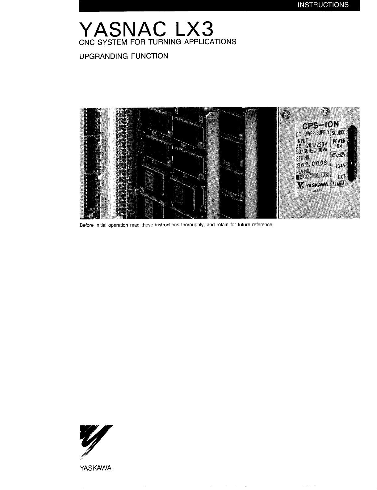
YASNAC LX3
CNC SYSTEM FOR TURNING APPLICATIONS
UPGRADING FUNCTION
Before initial operation read these instructions thoroughly, and retain for future reference.
YASUAWA
Page 2

Page 3

Specification upgrading of several functions is possible witn YASNAC
LX3 if it has a “Compact Interactive Function. ” (optional).
This manual describes these specification upgrading items and
operation.
The reader is requested to refer to the YASNAC LX3 Operator’s
Instruction Manual (TOE-C843-9.20) regarding those items that
are not covered here.
The data No. of the operator’s manual referred
to in this manual is ‘TOE-C843-9.20.
CONTENTS
1. STANDARD FUNCTION UPGRADING / 2
1.1 UPGRADING OF MULTIPLE CANNED
CYCLE FUNCTION / 2
1,2 UPGRADING AND CHANGE IN 9“
SCREEN DISPLAY ITEM / 6
1.3 UPGRADING 9“ EDIT OPERATION / 8
2. NEW TOOL SETTER FUNCTION / 9
2.1 GENERAL / 9
2.2 WRITING TOOL COORDINATE MEMORY / 9
2.3 WRITING Z-AXIS WORK COORDINATE
SYSTEM SHIFT AMOUNT / 11
2.4 OFFSET DISPLAY / 73
3. NEW COORDINATE SYSTEM
SETTING FUNCTION / 15
3.1 GENERAL / 15
3.2 DESCRIPTION FUNCTIONS / 15
3.3 PRECAUTIONS IN USING CONVENTIONAL
G 50 T*”* FUNCTION / 76
4. FS AUTO EDIT FUNCTION / 17
4.1 GENERAL / 77
4.2 INPUT AND OUTPUT / 77
4.3 DESCRIPTIONS OF FUNCTIONS / 78
4.4 PRECAUTIONS / 21
5. AUTO NOSE R FUNCTION / 22
5.1 GENERAL / 22
5.2 CONDITIONS TO MAKE AUTO NOSE
R COMPENSATION FUNCTION EFFECTIVE / 22
5.3 COMPENSATION CALCULATIONS OF AUTO
NOSE R COMPENSATION APPROACH AND
RETRACT / 23
5.4 CANCEL FUNCTION (G40, GO1) / 27
5.5 PRECAUTIONS / 27
6. Z-AXIS TOOL CHUCK BARRIER
FUNCTION / 27
6.1 GENERAL / 27
6.2 OPERATION / 27
6.3 PRECAUTIONS / 28
7. OTHER ADDITIONAL FUNCTIONS / 29
7.1 HIGH-FREQUENCY SKIP SIGNAL APPLIED FOR
MACHINE SETTER / 29
7.2 WORK SHIFT FUNCTION ADDED (G54) / 29
7.3 ABSOLUTE COORDINATE SWITCHING ADDED
WHEN MACHINE LOCK EFFECTIVE IS
SWITCHED TO INEFFECTIVE / 29
7.4 ADDITIONAL PARAMETER SWITCHING TO
AUTO NOSE R COMPENSATION AND COMMAND
T (INCLUDING G 50 T) FUNCTION / 30
7.5 HANDLE INTERPOLATION FUNCTION / 30
8. LIST OF NC PARAMETERS FOR
COMPACT INTERACTIVE FUNCTION / 31
-1-
Page 4

1. STANDARD
1.1 UPGRADING
FUNCTION UPGRADING
C)F
MULTIPLE CANNED CYCLE FUNCTION
1.1.1
Nose R compensation can be executsd with the G 70 to G 73 cycles even while
the finish profile program is being performed.
By this, G41 and G42 are added to the G codes that can be designated
by the blocks other than blocks Ns f and Nnf during finish profile program
execution.
During the rough finish and finish cycles, nose R compensation will become
effective during the finish cycle by the blocks instructed by G41 to G42.
Always instruct with the GOO or GO 1 moving command when instructing
G41/G42 to the block to start the finish profile program.
Commands with single-blocks are prohibited.
Upgrading (d) and (e) of par. 2.8.25.2, “Rules in programming” in the
YASNAC! LX3 Operator’s Instruction Manual.
.
Upgrading in (6) of par. 2.8.25.4,
tor’s Instruction Manual.
.
Upgrading in (2) of par. 2.8.25.5,
tor’s
Instruction Manual.
“NOTES” in the YASNAC LX3 Opera-
“NOTES” in the YASNAC LX3 Opera-
1.1.2
The T
during
gram become effective during the finish cycle (G70) and is disregarded during rough cutting of the external fclrm.
“ Upgrading in
YASNAC LX3 Operator’s Instruction Manual.
“ Upgrading in (1) of par. 2.8.25.4, “NOTES” in the YASNAC LX3 Operator’s
Instruction Manual.
1.1.3
A command with different start and end points in a finish profile program
can be executed during the G70 to G72 cycles.
- Upgrading in (a) of par. 2.8.25.2, “ Rules in programming “ in the
YASNAC LX3 Operator’s Instruction Manual (Condition of BA being parallel to Axis Z is lost.)
s Upgrading in par. 2.8.25.3, “Rules and cautions in programming finish
shape”
BA being parallel to Axis Z is lost.)
code command can be executed during the G70 to G73 cycles even
the finish profile program.
By thj.s, the codes F, S and T instructed during the finish profile pro-
(c) of par. 2.8.25.2,
in the YASNAC LX3 Operator’s Instruction Manual (Condition of
—
“ Rules in programming” in the
1.1.4
Execution using finish allowances lJ and W as stock removal allowances is
possible during the cycles G70 to G73 if both stock removal allowances I and
–2-
Page 5

K are omitted. Upgrading is possible with the related parameter # 6009 D1
= 1.
1.1.5
The recessing fixed cycle
(number of cutting-off stages) and Command B (cutting-off bite blade width)
to the functions G74 (end face cutting-off cycle) and G75 (outside diameter
cutting-off cycle) .
Given the following command,
(1)
- Upgrading in (1)
G 74X (U)
of par. 2.8.25.6 of the YASNAC LX3 Operator’s
.Z(W) _l_K_D_A_B _ F(E) ._ (RI);
—
I
can be executed by adding the Command A
G74 executes the cycle as shown
f ~ -
1’
~ –.—. — AMOUNT OF RETRACT ,QT
‘LEEDCOMMAND
BLADEWIDTH
(WITHOUTSIGNS)
OF CUTTING-OFF
NO,
STAGES(WITHOUT
CUT BOTTOM(wlTHOuT SIGNS)
CUTTING-OFFAMOUNT IN
z-Axis DIRECTION(wlTHOuT SIGNS)
MOVE AMOUNT
DIRECTION(WITHOUTSIGNS)
IN X-AXIS
SIGNS)
in Fig. 1.
Manual.
L
+x
R: RAPID FEED
F: F CODE FEED
d: PULL BACK AMOUNT (SETTING # 6208)
—— Z-AXISCOORDINATE
‘--— X-AXISCOORDINATEAT
NO. OF STAGES
POINT c (WITH SlGNS)
POINTB (WITH SIGNS)
AT
START POINT
WIDTH
-+2
Fig. 1 G7’4 Cycle Execution
-3-
Page 6

1.1.5 (Cent’d)
(2) Given the following command,
“ Upgrading in (1) of par.
75x(u) __ z(w)
(3
—
2.8.25.7 in the YASNAC LX3 Operator’s
_l_K__D_A_B– F(E) – (R l);
—
——– X-AXIS COORDINATE AT
(175 executes the cycle as shown
TTT
~-
~--—-—– NO. OF CUTTING-OFF
—— MOVE AMOUNT IN Z-AXIS
— CUTTING-OFF AMOUNT IN
--—
Z-AXIS COORDINATE AT
POINT B (wITH SIGNS)
POINT c (wITH SIGNS)
DIRECTION (WITHOUT SIGNS)
x-Axis DIRECTION (WITHOUT SIGNS)
,STAGES (WITHOUT SIGNS)
AMOUNT OF RETRACT AT
CUT BOTTOM (WITHOUT SIGNS)
FEED COMMAND
BLADE WIDTH
[wlTHOuT siGNs)
in Fig.2
Manual.
B
‘-T
n~
a
L
z
R: RAPID FEED
F: F CODE FEED
d: PULL BACK A!AOUNT (SETFING $ 6209)
R
F
R
R
K
w--l
BLAADE W ID,TH
A
d
START
I
POINT
U/2 I NO. OF STAGES
I
I
x
-+Z
Fig. 2 G75 Cycle Execution
–4–
Page 7

1.1.6 Upgrading of G76 Thread Cutting Cycle Function
The final nth cycle specified by L is executed by adding command L to
(1)
original G76 command.
G76X (U)_ Z (W) _
LO : Executes the
L1 : Executes the
final cycle.
Ln : Executes the
final cycle.
When n is a
cycles (n2N) , a
Zig zag cutting
(2)
adding command
G76X (U)– Z (W) -
The following plunges are obtained by command P :
Without P :
P,
P,
P3, P4, P5 ““”” :
I_ K_ D_F(E) _A_L ;
command of the final cycle.
commands in one cycle before the final cycle and the
commands from nth cycle before the final cycle to the
larger number than the number (N) of normal cutting
normal cutting cycle is executed.
with constant cutting
P to original G76 command.
I–K–D– F(E)– A_ P_;
Constant normal cutting amount, one-blade cutting
Constant normal cutting amount, one-blade cutting
Constant normal cutting amount,
Constant normal cutting amount, one-blade cutting
amount can be performed by
zig zag cutting
BLADE TIP
\\ \ iw-—
‘:!5--‘TH5iiiid
B9
Fig. 3 Constant Cutting Amount, Zig Zag Cutting
-5-
-3RD ~111111
Page 8

1.1.7 Dwell Added to G74 and G75 C:ycles
Dwell can be executed on the hole bottom by setting parameter ( # 6214) to
G74 or G75. When command A is provided (with number of’ stages) , dwell
is executed on the hole bottom of the last step.
#6214 O – – 65535 l=lms
1.1.8
Precautions in Upgrading of Multiple Canned Cycle Function
The following conditions are added to pars. 1.1.1, 1.1.2 and 1.1.3.
(1)
Upgrading becomes effective with the related parameter # 6011 D1 ==1.
(a)
This upgrading increases the maximum memory capacity of the finish
(b)
profile programs to 39 blocks.
Change in (2) of par.2.8.25.l in the YASNAC LX3 Operator’s Manual.
(2)
Precautions to G74/G75 upgrading in par.1.5.
If neither Command A nor Corr.mand B is given, the execution will be
(a)
the same as in previous G74/G’75.
If Command B only is given, blade width shifting is executed at the
(b)
beginnj.ng and end of G74/G75 as mentioned in detail below:
(i) The first motion is shifting by the blade width in the X-axis co:m-
ma.nd direction with G74 and in the Z-axis command direction with
G75 from the position of the block immediately before G74/G75.
(ii) The last motion is returning to the position of the block immedi-
ately before G74/G75 after being shifted by the blade width
amount.
If Command A only is given, o:dy retract is executed without executing
(c)
blade width shifting.
If Command A is given, the pull back amount with G74 and G75 will be
(d)
the set amount of # 6208 and 6209.
Pecking is not performed if this is
“o.”
Addition to par. 2.8.25.6,
“
Instruction Manual
Alarm 96 with the groove width < B (blade width) command.
(e)
“NOTES” in the YASN.AC LX3 Operator’s
UPGRADING AND CHANGE IN 9“ SCREEN DISPLAY ITEM
1.2
Basically, this function is upgrading of and changes in the 9” character
CRT. The same functions are obtained with the compact interactive function
also.
1.2.1 Upgrading
The program directory menu was displayed in the alarm function.
(1)
By upgrading, the menu is displayed in the program function.
Therefore, the alarm function does not show a program directory
By depressing ~ in the program function regardless of the
the program directory and program menu are shown cyclically.
m
-6-
menu.
mode,
Page 9

The program directory menu is displayed when the operation returns to the
program
another function.
The page key in the program directory menu is operated by the same
method as before.
(2) The external present value display can be changed to “O” by the opera-
function after changing from the program directory menu to
tion in the all-position menu
display can be changed to
all-position menu is displayed.
Change the value of the external current value display X-
(a) ❑ t~ axis to ()
(b) ❑ ❑
II ~~~II
(c)~\(=]”-@:
The values other than the external current values do not change.
Similar operation is possible also with the external current value menu.
:
: Change the value of the external current value display Z-
axis to “O.”
Change the values of the external current value display
X and Z axes to “O.”
~p] ~ .
“O” by the following key operation when the
The external present value
1.2.2 Changes
“R” was displayed after No.51
(1)
However, this has been deleted.
The first display when power
(2)
However,
played in the all-position display has not changed.
There were independent position increment displays. However, these dis-
(3)
plays are now eliminated.
now the first display
of the offset display.
was turned on was an alarm display.
is the all-position display. The data dis-
The displays change cyclically in the following sequence if the page
key is depressed in the position function mode:
1. All-position display
2. Program restart information display
3. Display for remaining numbers of pulses of stored stroke limit
4. Spindle PG pulse number display
5. Servo position deviation display
6. Command pulse integration register display
7. External current value display
8. Current value display
By depressing OPS
(4)
cyclically:
1. All-position display
2. Spindle PG pulse number display
3. External current value display
4. Current value display
function key the following four menus are displayed
•1
-7-
Page 10
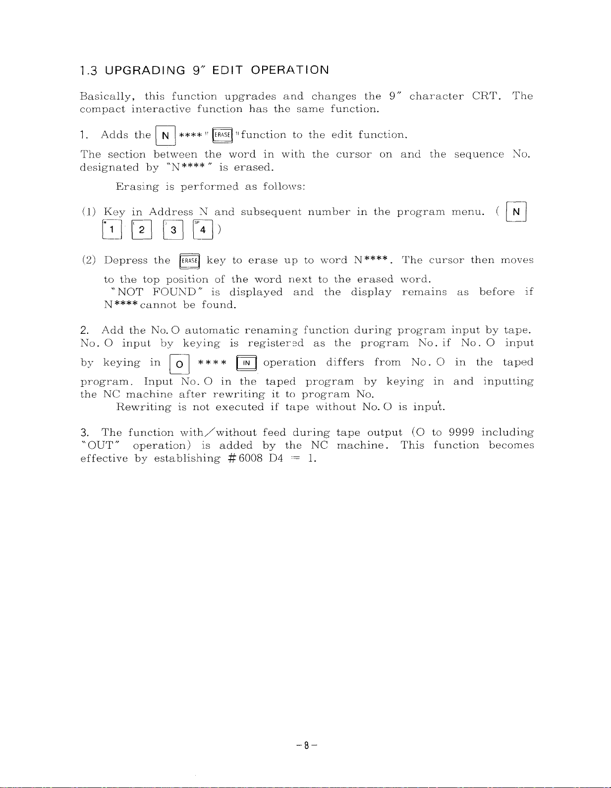
1.3 UPGRADING 9“ EDIT OPERATION
Basically, this function upgrades and changes the 9” character CRT. The
compact interactive function has the same function.
1.
Adds the ~****1~
The section between the word in with the cursor on and the sequence No.
designated by “N**** “ is erased.
Erasing is performed as follo~vs:
(1) Key in Address N and subsequent number in the program menu.
El El
(2) Depress the
to the top position of the word next to the erased word.
“ NOT FOUND “
N **** cannot be found.
2. Add the No. O automatic renamin~ function during program input by tape.
No. O input by keying is registered as the program No. if No. O input
by keying in 0
❑ rg)
ERASE key to erase up to word N****. The cursor then moves
❑
❑
program. Input .No. O in the taped program by keying in and inputting
the NC machine after rewriting it to program No.
Rewriting is not executed if tape without No. O is inpu’t.
ERASE II function to the edit function.
is displayed and the display remains
**** lN
operation differs from No . C) in the taped
n
( @
as before if
3. The function with/without feed during tape output (O to 9999 including
Ourr “ operation) is added by the NC machine.
“
effective by establishing # 6008 D4 = 1.
This function becomes
-8-
Page 11

2. NEW TOOL SETTER FUNCTION
2.1 GENERAL
Offset amounts and work coordinate system shift amounts can be written
automatically by manual operation even if the machine is not equipped with
a touch sensor.
This function simplifies setup during tool change.
This function differs from the previous tool setter function with a touch
sensor in tool coordinate memory value and in work coordinate shift amount.
The previous tool coordinate memory data was the differential distance
value between the touch sensor and the tip of the selected tool. This has
been changed to the differential distance value between the workpiece end
face and the tip of the tool.
been changed the shift amount from the projected home position to that from
the workpiece end face.
However,
function is called the new tool setter function.
the approach to the coordinate system does not change. This
2.2 WRITING TOOL COORDINATE MEMORY
Regardless of whether or not a measuring tool for a setter in the machine
exists, the tool coordinate memory amount can be written by manual operation as follows.
The tool coordinate memory amounts written in this case will be the
differential distance value between the workpiece end face and the tip position of the applicable tool.
The work coordinate system shift amount has
2.2.1 Writing Procedures
Home position return is executed by manual operation.
(1)
Mount the workpiece.
(2)
Set the tool coordinate memory value writing mode setting (6001 D6) to
(3)
\.
by this setting.
The display automatically changes to the ~~~
SHIFT) display as shown in Fig.
Select the machining tool.
(4)
The tool coordinate memory matching the tool post No. (tool post No.
input in # 1317) selected at this time is automatically selected.
tool coordinate memory No. is automatically selected, memory No. selection by the cursor or by the page key is prohibited.
cursor is moved to the tool coordinate memory No. by operating
cursor key or page key.
Make one cut of the workpiece skin.
(5)
( “PST 1” key ON in compact interaction). The write mode is set
1. “
~ function OFFSET (TOOL-
3 and the ~~s lamp blinks.
This function is effective only if parameter # 6020 D3 = 1. If the
If the tool coordinate memory No.
~
n
is not selected automatically,
the
the
–9–
Page 12

2.2.1 Writing Procedures (Cent’d)
Have the Z-axis only retract a:~d stop the spindle, keeping the X-axis
(6)
as it is.
Measure the workpiece diameter.
(7)
If the above setting is not turned on,
(8)
picture TD** Of the oFs
By inputiing the NIXnworkpiece diameter and WR
(9)
memory
(Tool coordinate memory
(10) Make one cut of the workpiece end face.
(11) Have the X-axis only retract and stop the spindle, keeping the Z-axis
as it is.
(12) Input MZ 0 and WR to automatically write in the tool coordinate
memory
(Tool coordinate memory “Z”
(13) Operate (4) to (12) for all tocls, both for X and Z axes.
(14) Set the tool coordinate memor~r value write mode setting (# 6001 D6) to
The write mode is cancelled a~d the o~s lamp stops blinking.
o
“X” is automatically written by the following calculation:
❑ n ❑
“Z” by the following calculation.
“METER 1” key OFF in compact interaction.)
“o” .
(
r7
u
a
function manually.
“X” ) = (workpiece diameter)
I = – (Position machine “Z” value)
select the tool coordinate memory
, the tool coordinate
(Position machine “X” value)
~
a
Precaution :
Tool coordinate memory value write
position return is not performed even once after turning on power.
mode setting is not effective if home
-1o-
Page 13

2.3 WRITING Z-AXIS WORK COORDINATE SYSTEM SHIFT AMOUNT
2.3.1 Writing Procedures
Home position return is executed by manual operation.
(1)
Mount the workpiece.
(2)
Set work coordinate system shift value writing mode setting (# 6001 D5)
(3)
to “l. ”
the write mode is set up.
At this time, OFFSET (WORK-SHIFT) display of the ~~~ function auto-
matically changes to TOO and the ~ function key lamp blinks.
( “PST 2“ : key ON in compact interaction. ) After this setting,
~
n
>
OFFSET(WORK-SHIFT)
~
~
02000 Noooo
d
EDIT
mmmmr==m=d
220.XOO0 20.ZOO0
I
Fig. 4 Work Coordinate System Shift
Display (Compact Interactive Function)
Make one cut of the workpiece end face.
(4)
Have the X-axis only retract, keeping the axis Z as it is.
(5)
Measure the workpiece cutting allowance.
(6)
Input
(7)
ing calculation is automatically written in the work coordinate system
shift memory “Z.”
input in # 1317.
❑ m •1
cutting allowance and WR . The result of the follow-
The tool offset memory matches the tool post No.
(Work coordinate system shift memory “Z” )
= (Cutting allowance) – (Tool coordinate memory “Z” value)
– (Position machine “Z” value)
Changing Z-axis work coordinate system shift amount.
(8)
If further shifting of the program is desired (e.g. a cutting allowance
(a)
from the workpiece end face) ,
can be rewritten for both the X and Z axes by MDI operation.
the work coordinate system shift memory
-11-
Page 14

2.3.1 Writing Procedures (Cent’d)
Calculate the shift amount, depl-ess the
value to add the value keyed in to the value presently displayed.
The code for addition is by #6018 D6.
# 6018 D 6 =
# 6018 D 6 = 1 : Workpiece shift amount – cutting allowance amount
The procedure for rewriting the work coordinate system shift memory
“X” value by
# 6018 D 6 = O : Workpiece shift amount
# 6018 D 6 = 1 : Workpiece shift amount
Normally, the ~ and numeral keys are
(b)
changes such as cutting allowance values
DE]
and
Set the writing mode setting (# 6001 D5)
(9)
shift memory value to “O.” ( “PST 2“ and
ion. ) The writing mode is cancelled and the OFS
(10) By manual home position return after changing the work coordinate
or w❑key or by inputting p
WF~again.
system shift memory,
If parameter # 6011 DO = 1 (if the tool coordinate memory No.
follows the last two digits of ‘1’ * * SS ) , refer to the Coordinate Setting
Operator’s Instruction Manual, Work coordinate system
performed in manual home position return.
O : Workpiece shift amount + cutting allowance amount
(with W code)
(with W code)
U is the same.
❑
(with code U)
(vith ‘code U)
—
❑
the work coordinate system is automatically set.
Norm
+ cutting
cutting
effective in this case. Minute
are input by adjusting by the
z?
n
~
of the work
key OFF in
~
a
key and input the
allowance amount
allowance amount
cutting allowance value
coordinate system
compact interact-
lamp
stops blinking
setting is not
Precaution :
Mode setting to write work coordinate system shift memory
effective if home position return is nob performed even once after
on.
Z-AXIS WORK
I SHIFT AMOUNT
COORDINATE
SYSTEM
,1
Z-AXIS TOOL COORDINATE
MEMORY VALUE
I
I r-
r
Fig, 5 Cc)ordinate .System
-12-
values is not
turning power
POINT)
ZERO
Page 15

2.4 OFFSET DISPLAY
The following offset display will be shown if the new tool setter function is
added.
The following displays can be changed cyclically by depressing the OFS key.
~
The
OFS key is disregarded during the PST 1 or 2 mode.
n
~
a
Fig. 6 Display No.1
Work Coordinate System
(Compact Interaction)
Fig. 7 Display No.2
Tool Offset Memory Display
(Compact Interaction)
Shift Display
OFFSET(WORK-SHIFT)
d
EDIT LSK
220.XOO0
POSITION (MAc! H&R}
x
z
Izmlmmmm
I
I OFFSET (TOOL-WEAR)
I
TX
t.:.
%!
03 : 0 :
04 . 0 .
05 . 0 .
Pos I’po N
00090 NOOOO
30.ZOO0
o
00090 .Noooo
z
o . 0:
0 . 00
0 . 00
0 . 00
0 . 00
RDY
R
EDIT
Mm=Hb_d
-13-
z
LSK
RDY
Page 16

;Z.4 OFFSET DISPLAY (Cent’d)
Fig.8 Display No.3
Tool Coordinate Memory Display
(Compact Interaction)
OFFSET(TOOL-WEAR)
00090 Noooo
-14-
Page 17

3. NEW COORDINATE SYSTEM SETTING FUNCTION
3.1 GENERAL
This function has a new approach to coordinate setting which is entirely
different from previous ones.
(a) The approach to coordinates is machine coordinate sYstem.
(b) The blade tip point can
(absolute) .
(c) Coordinate system setting is not required in programs.
3.2 DESCRIPTION OF FUNCTIONS
How and on what timing are coordinate system set?
3.2.1 Operational Expressions for Coordinates Setting
Various types of timing are used to set coordinates.
However,
coordinate system :
(X-axis coordinate value)
= (Machine position) +
(Z-axis coordinate value)
—
—
(Machine position) +
The machine position is the position machine.
(1)
Tool coordinate memory value Nos. are divided into
(2)
on whether the timing of next coordinate system
automatic.
The work coordinate system shift amount is data of
(3)
the following operational expressions are always used in setting
+ (Work coordinate system shift amount)
+ (Work coordinate system shift amount)
The features are shown below :
always be displayed as the current value
(Tool coordinate system memory value)
(Tool coordinate system memory value)
two systems depending
setting is manual or
offset T 00, X, and Z.
3.2.2 Coordinate System Setting Timing in Manual Mode
In the manual mode, coordinate system is set on timing ( a ) to mentioned
below (c) . The tool coordinate memory Nos. in this case are produced based
on tool No. binary values set from 1/0 inputs # 13174 (TP1) to # 13178 (TP8)
and are used for arithmetic operations.
Set up is performed in two modes, namely, setting up inside the NC
machine and coordinate system setting by sequencer requests. On a sequencer
request, coordinate system setting is executed and Output # 121974 (coordinate
system setting end output ) is turned on if Input # 13127 ( coordinate system
setting request input) turns on.
(a) At the tire-e of ~he home ‘position return.
(b) When the blade tip contacts the sensor with the tool setter during measure-
ment.
(c) When the turret is indexed manually.
Precaution :
Coordinate system setting in the manual mode is not performed if Parameter
#60 11 DO = 1. If the tool coordinate memory No. follows the last two digits
of T**$ $, refer to par. 2.3.
-15-
Page 18

:3.2.3 Coordinate System Setting Timing in Auto Mode
(~~ordinate
:he T code. In this case, the tool coordinate memory No. uses the turret No. or
offset No. instructed to tha command display for arithmetic operations.
Unlike the T code command b~’ the conventional
:he T code command in the coordinate system setting
as follows :
The tool coordinate memory No. can be selected to
last two digits of T4 dig-its by setting parameter # 6011
Depending on parameter setting, the execution
:setting differs as
(1) Setting first
two digits
(#”6011 DO =
Precaution :
The tool coordinate rnernory No. will be (tool No. + 50)
For this reason, select data of (tool No. + 50) as the tool coordinate memory
value.
By executing the T *‘K $$ command,
(a)
the selected tool coordinate memcry No. is set after the tool post moves by
the offset amount to the compensation No. simultaneously with turret
calling regardless of the tool post location.
T * *O O command executes turret calling and offset value cancel shift
(b)
sirnulta.neously regardless of the tool post location. Then coordinate system
is set corresponding to the selected coordinate memory No.
By this coordinate setting,
(c)
always set.
(2)
Setting last
two digits
(#6011 DO = 1)
settingis performed in the auto m~de if the turret is called by
compensation method,
specification instructs
be set in the first or
DO.
of coordinate system
o)
T** $$
L
COMPENSATION NO. (WEAR AMOUNT COMPENSATION)
01 TO 1601 T049 (B IADE TIP NOSE RI
- TOOL NO (TOOL COORDINATE MEMORY NO. )
01 TO 16/01 T049
coordinate system corresponding to
the coordinate system at the tool blade tip are
‘-- T
-—
‘-— (TOOL COORDINATE MEMORY NO )
COMPENSATION NO. (WEAR AMOUNT COMPENSATION)
—
01 T3 16/01 T049 (BLADE TIP NOSE R)
TOOL NO 01 TO 16/01 TO 49
The tool coc)rdinate memory No. will be compensation No. + 50. For this reascn,
tool coordinate m.emo]jy value will select compensation No. + 50.
the
By executing the T * * $$ command coordinate system corresponding to
(a)
the selected tool coordinate memory No. is set after moving by the offset
amount to the compensation No.
simultaneously with turret calling regardless of the tool post location.
By executing the T‘~ * 00 command moving of cancel operation of the offset
(b)
amount simultaneously with turret calling is executed regardless of the
tool post location.
By this set up, coordinate system at tool blade tip are always set.
(c)
PRECAUTIONS IN lJSING CONVENTIONAL G 50 T**** FUNCTION
3.3
Do
not issue the G 50 T * * * * command when using in the coordinate
setting specification.
Coordinate system setting is not executed at this time.
system
An error results if the command is issued.
-16-
Page 19

4. FS AUTO EDIT FUNCTION
4.1 GENERAL
This function creates optimum programs by storing effective values of feed
speed and spindle revolution speed during auto operation and feeds them back
to the NC part program.
and spindle revolution speed
In the following descriptions,
(S code) are called “FS.”
4.2 INPUT AND OUTPUT
The 1/0 signals needed in FS editing are as follows :
4.2.1 Input
FSCM (# 13134) :
(1)
feed speed (F code)
FS edit mode. Prepares for FS memory and for FS memory
ing FS editing when the signal is on.
FSMEM (# 13135) :
(2)
FS memory. Call up feed speed and spindle revolution speed
nal memory during
FSCH (# 13136) :
(3)
FS memory change.
NC PART program
FSCLR (# 13126) :
(4)
FS data clear. Clears the FS data stored when the signal is on.
4.2.2 Output
FSMD (# 12183) :
(1)
During FS edit mode. The signal shows that FSCM is on and that FS storage
and FS memory edit is ready. Feed speed and spindle revolution speed are
cancelled when the status of this signal changes from on to off.
FSCE (# 12184) :
(2)
FS memory change end.
status of FSCH becomes on and data is reflected on the NC PART program.
The status of this signal changes to off if the status of FSCH becomes off
again.
auto operation when the signal is on.
Reflects data called up in automatic operation in the
while auto operation pauses when the signal is on.
The status of this signal becomes on when the
change dur-
in the inter-
FSCLRE (# 12233) :
(3)
FS data clear end. The status of this signal becomes on if the status of
FSCLR becomes on and if the stored FS data is cleared. The status of this
signal changes to off if the status of FSCLR becomes off again.
-17-
Page 20

4.3 DESCRIPTIONS OF FUNCTIONS
Rough calculations of FS data only m--e programmed by the NC PART program and the program is optimized by feed and spindle override after cutting.
The optimum data and positions
stored in the memorY contained in the NC machine. By turning on FS
change input, the data and positions a::e reflected in the part program.
4.3.1 Operation Procedures
Set up the system ready to operate.
(1)
(2)
Search the operation program in the memory mode.
Trun on FSCM.
(3)
Check that FSM13 has been output and start memory operation.
(4)
Change the feed or spindle revolution speed for optimum value.
(5)
Make FSMEM when cptimum condition is achieved.
(6)
Execute steps (5) and (6) repetitively.
(7)
Set up the operation pause status (label skip status) .
(8)
Turn on FSCH. Put the execution values stored in FSMEM in the PART
(9)
program.
of actual cutting in the program are
memory
(10) Turn off FEFSCH.’SCE breaks.
(11) Turn off FSCM. The data stored in step (5) and (6) are cancelled.
4.3.2 Timing Chart
,Sc. ~
(PC-NC) \
FSMD
(NC+ PC)
\l
/
L
INTER=L DATA CANC’EL
-AuLJUL
(PC+ NC’
Y./
250 m sec OR MORE
FSCH
(PC-NC)
\A
FSCE ~
(NC+ PC)
FSCLR
(PC+ NC)
FSCLRE
(NC+ PC)
NC PART PROGRAM CHANGE
/ ,’4
v
DATA CLEAR
1
-18–
Page 21

4.3.3 Examples of FS Editing
The following two edit patterns are available by selecting parameter # 6008 D6.
(1) F/S is edited every time (# 6008 D6 = O)
(a) (Before editing)
1000 ;
o
N1G28UOWO;
N 2 G50 TS1OO ;
N 3 TO1O3 ;
N 4 G40 G97 G99 S1500 M08 ;
N 5 GOO X43.236 Z1O. M03 ;
N6Z1. ;
N 7 GO1 X39.216 Z–6.5 F.15 ; - F override 80% S override 110% FSMEM is
on.
N 8 X38.864 ;
N 9 G03 X18. Z–20.142 R19.85 ;
on.
N 10 GO1 Z–20.5 ;
N 11 X12. Z–22.232 ;
N 12 G40 X1O. F1. ;
.
.
.
.
.
.
.
.
- F override 50 YO S override 80% FSMEM is on.
- F override 60 YO S override 100 YO FSMEM is
(After editing)
(b)
1000 ;
o
N
1 G28 UO WO ;
2 G50 TS1OO ;
N
N
3 TO1O3 ;
4 G40 G97 G99 S1500 M08 ;
N
N
5 GOO X43.236 Z1O. M03 ;
N
6 Z1. ;
N
7 GO1 X39.216 Z–6.5 F.12 S1650 ; - F override 80% S override 110%
N
8 X38.864 ;
N
9 G03 X18. Z–20.142 R19.85 F.09 S1500 ; - F override 60 Yo S override” 100 YO
10 GO1 Z–20.5 ;
N
N
11 X12. Z–22.232 F.08 S1200 ;
N
12 G40 X1O. F1. ;
.
.
.
.
.
.
.
.
.
- F override 50 YO S override 80%
-19-
Page 22

4.3.3 Examples of FS Editing (Cent’d)
(2) F/S is edited retroactively (# 16008 D6 = 1)
In this case F/S is edited retroactive to the point where FSMEM was
last closed.
(Before editing)
(a)
1000 ;
o
1
G28 UO WO ;
N
2 G50 TS1OO ;
N
N
3 TO1O3 ;
N
4 G40 G97 G99 S1500 M08 ;
N
5 GOO X43.236 Z1O. M03 ;
N
6 21. ;
N
7 GO1 X39.216 Z-–6.5 F.15 ; - F override 80% S override 110% FSMEM
is on.
8 X38.864 ;
N
N
9 G03 X18. 2–20.142 R19.85 ; - F override 60% S override 100% FSMEM
E on.
10 GO1 2–20.5 ;
N
11 X12. Z–22.232 ; -
N
N
12 G40 X1O. F1. :
.
.
.
.
.
F overri3e 50% S override 80% FSMEM is on.
(After editing)
(b)
o
1000 ;
N
1 G28 UO WO ;
2 G50 TS1OO ;
N
N
3 TO1O3 ;
N
4 G40 G97 G99 S1200 M08 ; - S override 80% is reflected.
N
5 GOO X43.236 Z1O. M03 ;
N
6 Z1. ;
N
7 GOl X39.216 Z—6.5 F.08 ; - F override 50% is reflected.
N
8 X38.864 ;
N
9 G03 X18. 2–20.142 R19.85 ;
N
10 GO1 2–20.5 ;
N
11 X12. Z–22.232 ;
N
12 (340 X1O. F1. ;
.
.
.
.
.
.
-20-
Page 23

4.3.4 Specification Conditions for FS Editing
Conditions to store FS data in internal memory
(1)
(a) During FSMD output.
(b) During automatic operation (STL is on).
(c) Actual feed and spindle revolution speed values are stored by the rise
of FSMEM.
(d) All the data stored in (3) are cancelled by the fall of FSCM.
(e) The maximum memory cycles (the cycles to turn on FSMEM ) are
128 cycles.
(2) Conditions to reflect FS data in part program
(a) During FSMD output.
(b) During automatic operation pause. (Label skip status)
By changing the status of FSCH from off to on under this condition,
F/S data are inserted in each block in accordance with the stored
data.
4.4 PRECAUTIONS
(1) The newest feed and spindle revolution speeds become effective if the
status of FSMEM is on more than twice in one block. The FSMEM count
is not increased.
(2) FS data is inserted in the sub-program itself if the status of FSMEM is
on during a sub-program.
are also called up.
Caution must be exercised as other programs
(3) FS editing during a compound fixed cycle allows only F/S of O.D. rough
cutting cycles.
(4) Blocks in on status are changed with F if FSMEM is on in constant pe-
ripheral speed control. Blocks are not changed with S.
(5) The CYCLE START switch does not operate while FSCH is on even if
it is depressed.
(6) F/S data is stored if FSMEM is on during cutting.
(7) S data is stored if FSMEM is on during rapid feed.
(8) A warning is issued if FSMEM is on more than 128 times, and data are
not stored even if FSMED is on further.
(9) FSMD is not on even
operation.
(10) The CYCLE START switch does not operate while FSMEM is on.
if the status of FSCM is on during automatic
(11) A warning is issued if editing is performed while FSMD is on after
finishing FS editing.
-21_
Page 24

!5. AUTO NOSE R FUNCTION
5.1 GENERAL
Nose R compensation is performed b~ the nose R control point (O to 9) corr~-
mand and by G 41 and G 42. Selection of compensation side moving from a n
end face to outside diameter becomes simple. By executing the T command,
tool, as well as the nc]se R and control point corresponding to the toc,l,
a
are selected.
At this time, coordinates of the tool based on this machine coordinate
system are set. After issuing the T command,
tions are made by the control point and by G 41 and G 42.
5.2 CON DITONS TO MAKE AUTCI NOSE R COMPENSATION
FUNC1-ION EFFECTIVE
Auto nose R compensation becomes effective by four conditions, namely,
(designation of projected blade tip pcints set by compensation No., by nose R
radius, by setting of the compensation side by the G 41 and G 42 commands,
and by the T code command. They are described below.
5.2.1 Designation of Proje~ted Tool Tip Points
Projected edge point direction
(1)
nose R compensation calcul:~-
Auto nose R is determined by designating the projected tool tip point
position by using a numeral between O and 9 to regulate the shift direction. The directions a:~e shown in Fig.9 (X PIUS specification).
2 6
7
H=
3
(2)
Method to set projected
tool tip point.
Projected tool tip points
can be set using the off-
set screen. (Se; Fig. 13)
09
8
1
5
4
Fig. 9 Projected Tool Tip Point Direction
OFFSET (T OOI.-W’EAR)
[
,.
01234 NOO03
0~--12%4. 567 -12$4. 56’J 12!. 456 i
02 . 0
03 . :
(a) Select the ~ funct-
ion.
(b) Select the compensa-
tion memory of the
matching
from T 01 to 49.
(c) Input
~
I-E
are
tool
tip points.
tool
❑ , [~ a:xl
by MDI if there
three projected
No.
04 !:
05 : 0
0.
POSITION (EXTERNAL)
x–1234. 567
Z 1234.567
EDIT
LSK RDY
mmmr=w=z
\ 1
Fig. 10 Offset Display (Compact Interactive)
I
-22–
Page 25

5.2.2 Setting Tool Tip R Data Memory
(1) Setting nose R data memory
The nose R data memory can be set on the offset display as shown in Fig. 10.
(a) Select the ow function.
(b) Select the compensation memory of the corresponding to tool No. from
T 01 to T 49.
~
n
(c) Input R
8 and wR by MDI if the nose R data is 0.8 mm.
cm ❑
5.2.3 G41 and G42 Commands
The compensation direction can be instructed during cutting by the G 41 and
G 42 commands. (X plus specification)
G 40: Nose R compensation OFI?
G 41 : Left side of moving direction is nose R center.
G 42 : Right side of moving direction is nose R center.
5.2.4 T Code Commands
The T code No. (4 digit) commands select coordinates system, wear compen-
sation and nose Rs.
Refer to Sect. 3,
for details.
T**
$$
TT
‘COmpenSatiOn NO. (w EAR AMOUNT COMPENSATION)
~TOOL NO. EDGE (TOOL COORDINATE MEMORY NO. )
“ NEW COORDINATE SYSTEM SETTING FUNCTION, ”
01 TO 16/01 TO 49 (NOSE R)
01 TO 16/01 TO 49
5.3 COMPENSATION CALCULATIONS OF AUTO NOSE R COMPEN-
SATION APPROACH AND RETRACT
In auto nose R compensation,
from the conventional YASNAC LX3 nose R compensation
5.3.1
Block compensation G 00 -+ G 00 is not performed.
Positioning only is performed.
the following functions have been upgraded
function
-23-
Page 26

!5.3.2
[n approach G 00 - G 01 (G 02, G 03), a vector (wall)
set on the tool to make compensation to prevent overcutting
In recess G 01 ( G 02, G 03) - G 00, a vector (wall) is
o make compensations as follows to prevent omission in cutting.
(1) Approach G 00- G 01 or recess G 01 ~ G 00
(a) If the direction of the cutting command moving axis is larger than 45”
relative to Z-axis ( I X/2 I > I Z I ) , a vector
is theoretically erected to make compensation calculations with the cutting
moving axis.
(b) If the direction o-f the cutting command moving axis is smaller than 45[’,
or is equal, relative to Z-axis
to X-axis is theoretically erected to make compensation calculations with
the cutting moving axis. The to~l moves toward this calculated position.
See Fig
12.
The tool moves toward this calculated position. See Fig. 11.
( I X/2 I < I Z I ) , a vector (wall) parallel
./
THEORETICAL
VECTOR X
(wall) parallel to Z-axis
is theoretically
and overshock.
theoretically set
Ss
z
Fig. 11
Example : 3 tool tip points
,/” , ,
/’ ,
/’
/“ ~ ,,
)’” ,/’
/ /’
L4RGER THAN,45’
?!?2
1
,“
Fig. 12
.@/
CJ(5 “
60,,
.
,-
(PARALLEL
(G42)
GO’I
7
=., ,
%
G@J (;4;,’ .
Fig. 13 Example of 3 Tool Tip Points
/“
THEORETICAL
\/EcTo R
(vERTlcAL TO Z-AXIS)Q+’
TO Z-AXIS)
THEORETICAL
VECTOR
i
Q/
C$’
/
—
———.——
GOO(G42)
-24-
Page 27

(2) Approach GOO + G02 (G03) or recess G02 (G03) + GOO
(a) If the, vector direction of the circular arc cutting command moving axis is
larger than 45° relative to Z-axis, a vector
theoretically erected to make compensation calculations with the cutting
moving axis. The tool moves toward this calculated position. See Fig. 14.
(b) If the vector direction of the circular arc cutting command moving axis is
smaller than 450, or is equal, relative to Z-axis, a vector
to Z-axis is theoretically erected to make compensation calculations with
the cutting moving axis. The tool moves toward this calculated position.
See Fig.15.
THEORETICAL
(wall) parallel to Z-axis is
(wall) parallel
VECTOR x
LARGER THAN 45’
THEORETICAL VECTOR
%
Fig. 14
Example : 3 tool tip points
45’
z
AN
z
Fig. 15
/
/
THEORETICAL VECTOR
THEORETICAL
VECTOR
G03 (G4i~
Fig. 16 Example of 3 Tool Tip Points
-25-
45’ OR
MORE ;Z
?
#/
~>/
c+
G03 (G4;)
Page 28

5.3.3 Patterns of Auto Nose R Apprcach and Retract
0
C=3
Circular
45° or less
—
t
Linear
t
45° or more
—
/
–26-
Page 29

5.4 CANCEL FUNCTION (G40, GO1)
Auto nose R function can cancel G40 GO 1 X _ Z _ I _ K _ ; command. In addition
to cancel function of G40 GOO X _ Z —I _ K_;, GO1 has the same function.
This function makes a theoretical wall by command I or K in the block
before G40 GO1 command and executes nose R calculation.
5.5 PRECAUTIONS
(1) In G40 GOO X_Z
provided on the end point normal.
(2) In G51 independent block or G28 block, nose R complete cancel is exe-
cuted in the block immediately before G51 or G28.
(3) In G40 GOO X_ Z_ I_K_;,
indicated as
(4) When GO 1 and G41 (G42) are commanded simultaneously, the center
of nose R is provided on the normal of the starting point of the next block.
In canned cycle, the first block can be started up by GO1 G42, how-
ever, it cannnot be started up by the same command afterward.
(5) G40 GO1 X_K
as that of beveling command, however,
only when G40 command is provided.
“I” or “K” in the block immediately before G40 GOO.
_ ; or G40 independent block, the center of nose R is
node calculation is executed with vector
_ ; and G40 GO1 Z _ I _ ; have the same command format
cancel function has priority
6. Z-AXIS TOOL CHUCK BARRIER FUNCTION
Barrier for each tool in Z-axis direction is automatically set by setting the
length between absolute zero point and the barrier by extending normal
tool stored stroke limit function.
6.1 GENERAL
When # 13181 (tool range change) signal is input in the timing for changing
the tool, chuck barrier value corresponding to tool number is set in Z-axis
direction by reading the tool numbers set in # 13174 to # 13178 (TP1 to TP8) .
This function is effective when parameter # 6011 D4 = 1.
6.2 OPERATION
(1) Each tool coordinate memory value and work coordinate system shift value
is set in PST mode.
(2) A value of the length between the absolute zero point to a desired chuck
barrier in Z-axis direction is set in setting parameter (# 6573).
(3) Stored stroke limit 3 is effective. (# 6001 D2 = 1)
-27-
Page 30

6.2
OPERATION (Cent’d)
(4)
Stored stroke limit 3 setting parameter
( # 6507) in Z-axis direction is
set in the tool chan~ing timing in manual or automatic mode, by the
following operation :
# 6507 = # 6573 –- (Tool coordinate memory value +
Work coordinate system shift value)
--- —
1Z-AXIS WORK COORDINATE
SYSTEM SHIFT AMOUNT
I
Z-AXIS BARRIER(8 6507)
Z-AXIS
T(IOL
COORDINATE
=RY VALUE+
\ X-AXIS TOOL ‘
\
ABSOLUTE
ZERCI
PolN”r
Fig. 17 Coordinate System
COORDINATE
MEMORY
AMOUNT
REFERENCE ZERO
POINT
c
-
-’----+
/“-
I
6.3 PRECAUTIONS
The following conditions are required for effective functioning
(1) Stored storoke limit Z is availatlle as an option.
(~) when ~ool stored stroke limit is
value of Z-axis only can be reset.
a~~ailable, each tool stored stroke limit
-28-
Page 31

7. OTHER ADDITIONAL FUNCTIONS
7.1 HIGH-FREQUENCY SKIP SIGNAL APPLIED FOR MACHINE SETTER
When high-frequency skip signal is used together with sensor input signal
{X + OFST (#13201), X–OFST (#13202), Z + OFST (#13203), Z–OFST
(# 13204) ~, it will improve absolute accuracy of measured value.
High-frequency skip signal is switched by # 6011 D3.
X + OFST :
X–OFST[,
Z+ OFST; ~,
Z–OFST; ~\:
1 :
#6011 D3
7.2 WORK
The current
and
.,
# 6572 (Z) by G54 independent command.
Shift amount can be cancelled by G50 independent command.
.
X-axis coordinate value = Machine position
+ Tool coordinate value + Work coordinate system shift amount + # 6571
.
Z-axis coordinate value = Machine position
+ Tool coordinate value + Work coordinate system shift amount + # 6572
SHIFT FUNCTION ADDED (G54)
coordinate system can be shifted for setting amount of # 6571 (X)
Effective
0 : Ineffective
# 13201
# 13202
# 13203
# 13204
DINo (SKIP INPUT)
G54 ; Coordinate system shift effective
G~O ; Coordinate system shift ineffective
7.3 ABSOLUTE COORDINATE SWITCHING ADDED WHEN MACHINE
LOCK EFFECTIVE IS SWITCHED TO INEFFECTIVE
To prevent an error in coordinate systems when machine lock is ineffective
after drawing display at machine lock effective, absolute coordinate sYstem
is reset by the tool number currently provided when machine lock is switched
from effective to ineffective.
-29-
Page 32

“7.4 ADDITIONAL PARAMETER SWITCHING TO AUTO NOSE R
COMPENSATION AND COMIVAND T (I NcLu DING G50T)
FUNCTION
A parameter
:system setup function
command T (including G513T) function, is added.
#6011 D2 O : Auto nose R function and coordinate system setup
which switches
“by command T to normal nose R compensation and
function by cc~mmand T effective
1 : Normal nose R function and command T (including
G~OT) functi~~n effective
auto
nose R compensation and coordinate
7.5 HANDLE INTERPOLATION FUNCTION
7.5.1 General
When handle interpolation mode is commanded during program execution in
memory, tape or MDI mode, cutting speed commanded by GO1, G02 or G03 can
be controlled by turning the handle in the plus direction.
7.5.2 Operation
select handle interpolation mode to set by panel key or I / O input in
(1)
compact interactive function
monochrome display.
Setting # 6001 D4
; b~ setting parameter or I/ O input in 9”
1 : Effective
O : ineffective
1/0 Signal # 13066 1 : Effective
O : Ineffective
(2) Depress cycle start button.
“F” b links and cutting stops before executing GO1 (or G02, G03) program.
(3)
(4) The manipulator moves
and starts cutting.
The moving speed is in proportion to handle rotating speed and co:m-
mand F is overridden.
EXAMPLE : When 1 rotation/ sec = 100 Yo, the relation between rotation
speed and override is as follows :
# 6349 parameter
1 rotation/see or more
0.5 rotation/see 50%
0.01 rotation/see
0.01 rotation/see or less
(5) The manipulator stops moving
the minus direction.
(6) Turn off handle interpolation mode after cutting is completed.
while turning the handle in the plus direction
= 100 (pulse/see)
100VO
1YO
stop
when the handle is stopped or turned in
-30–
Page 33
7.5.3 Precautions
Turning the handle at 0.2 rotation / sec or more makes a constant move-
(1)
ment. If at 0.2 rotation/see or less, the movement is intermittent.
When turning off the mode during handle interpolation, the remaining
(2)
movement is executed by command F’.
In case of handle 2 axis specification,
(3)
Handle interpolation is ineffective during thread cutting.
(4)
Handle axis selection is not required for interpolation.
(5)
Handle interpolation mode is disregarded during automatic
(6)
handle offset.
Normally, the command is overridden,
(7)
ride selection switch.
In dry run,
(8)
override varies depending on feed override selection switch setting and
rapid traverse speed setting.
LIST OF NC PARAMETERS FOR COMPACT
8.
override varies depending on dry run speed.
only the first handle is effective.
disregarding setting of feed over-
Therefore,
INTERACTIVE FUNCTION
These parameters are needed to realize the compact interactive function.
Parameters (Fixed)
# 6009 D2
The compound compensation function
The T $$ ** command enables simultaneous setting of position
offsets and of coordinate system
mode
#6015 DO
#6015 D1
# 6016 D4
#6016 D5
1 : Effective
O : Not effective
The automatic X-axis coordinate system setting effective axis
1 : Effective
O : Not effective
The automatic Z-axis coordinate system setting effective axis
1 : Effective
O : Not effective
The automatic nose R function
1 : Effective
O : Not effective
The simple measured value direct input function
1 : Effective
O : Not effective
–31-
Page 34

8. LIST OF NC PARAMETEFIS FOR COMPACT
INTERACTIVE FIJNCTION
(Cent’d)
#
6016 D6
Parameters (Selective)
# 6008 D4
# 6008 D6
# 6009 D1
#6011 DO
The tool coordinate system setting function. The coordinate
system setting function by the T4-digit command
1 : Effective
O : hot effective
With or without feed during tape output by NC
1 : Without feed
O : With feed
During automatic FS editing
1 : F/S edited retroactively
O : F/S edited every time
U and W are used instead if I and K are not available wj th
G 71 to G 73.
1 : Effective
O : Not effective
The T *‘~ $$ command to make tool coordinate memory Nos.
1 : Lower 2 digits
O : Upper 2 digits
(Relatecl fixed parameter : # 6016 D6)
#6011 D1
#6011 D2
#6011 D3
#6011 D4
Setting Parameters
# 6001 D4
Enables the T code, G 41 and G 42 commands during com-
pound fixed cycles
1 : Effective
O : Not effective
Interlock of auto nose R function and coordinate setup
function by commancl T
1 : Effective normal nose R function and command T ( in-
O : Effective auto nose R function and coordinte system
Setter higkfrequency skip signal in machine
1 : Effective
O : Ineffective
Check barrier function for each tool
1 : Effective
O : Ineffective
Handle cc,rnpensation function
cluding G 50 T) function
setup function
1 : Effective
O : ineffective
-32-
Page 35

# 6001 D5
PST2 workpiece shift amount write request
1 : Effective
O : Not effective
# 6001 D6
# 6208
# 6209
#6210
#6211
#6212
PST 1 tool coordinate
1 : Effective
O : Not effective
G 74 recessing canned
Unit : Input unit
Set range :0 to 65535
G 75 recessing canned
Unit : Input unit
Set range :0 to 65535
G 74 recessing canned
Unit : Input unit
Set range : 0 to 65535
G 75 recessing canned
Unit : Input unit
Set range :0 to 65535
G 74/G 75 recessing
Unit : 1 == 100%
Set range : 0 to 127
system memory amount write request
cycle pull back amount
cycle pull back amount
cycle clearance amount
cycle clearance amount
canned cycle approach speed override
Enables override to F in approach speed after second recessing cycle.
#6213
#6214
# 6571
Reduces cutting amount of each cutting in units of 1 YO to
G 71 / G 72 cutting reduction override # 6004 (D 3 to D 7 )
or to cutting override. D * ( # 6004 or input override) *
(100 - (B 1) * # 6013) /100 = cutting amount of each cutting
D : Cutting amount
N : Number of cutting cycles
Unit: 1 = l%
Set range : 0 to 99
G 74, G 75 cycle hole bottom dwell time
Unit : 1 = lms
Set range : 0 to 65535
G 54 work shift function X coordinate
Unit : 1 = 0.001 mm or 0.0001 inch
Set range :
–99999999 to 99999999
NOTE : The NC machine automatically turns # 6001
when the new tool setter function is used.
Therefore, setting them is not possible.
shift amount
D5 and D6 on and off
-33-
Page 36

YASNAC LX3
19
CNC SYSTEM FOR TURNING APPLICATIONS
UPGRADING FUNCTION
TOKYO OFFICE OIWmachl Bldg, 16-1 Ohtemachl, Chlyoda-ku, Tokyo, iOO Japan
Phone (03)3284.911. Telex YASKAWAJ33530 Fax (03)3284-9034
SEOUL OFFICE 88? Floor Seoul Center Bldg 91-1 Sogong-Dong, Chung-ku, Seoul, Korea 1OC-O7O
Phone (02) ”776-7844 Fax (02)7532639
TAIPEI OFFICE Sh(m Hslang Tang Sung Chlang Bu[ldng 10F 146 Sung Chlang Road, Ta!pel Taiwan
Phone (02) 563-CO IO, -7732 Fax (02)567-4677
YASKAWA ELECTRIC AMERICA, INC.
Chicago-Corporate Headquarters 2942 MacArthur B1vd Northbrook, (L 600622028, US.A
Phone (708)291 2340 Fax (708)4982430
Chlcaao-Technmal Center 3160 MacArthu Bvd Northbrook, IL 60062-1917, USA
Phone-(708)2910411 Fax (708)291 1018
MOTOMAN INC.
805 Llocr!v Lane We;l Carroll[on, OH 45449 USA
Phone (513] 847-620C Fax (513)8476277
YASKAWAELECTRC EUROPE GmbH
Nleoerhochstadter Stta13e 73, 61476 KronbergOberhochstadt, Germany
Phorle (06173)9380 l“elex415660YASE [1 Fax (06173)68421
YASKAWA ELETRIC:O DO BRASILCOMERCIO LTDA
Rua Conoc Do IPmhztl 85°, Andar Sala51 SEP 01501 Sap PauloSP Brash
Phcme(Oll)35-’9ll Fax(Oll) 377375
YAstiWA ELECTRIC (SINGAPORE) PTE. LTD.
Head Off Ice CPF bldg, 79 Rob!nson Roacl # 1305, %gapore 0106, SINGAPORE
Phone 2211-530 Telex (87)24890 YASKAWA RS Fax 2245854
Service Center 221 Henderson Road # 17-20 Henderson Bulldlng Singapore 0315 S’NGAPORE
Phcme 276-7407 Fax 276-7406
YATEC ENGINEERING CORPORATION
Snen Hslang Taog Sung Ch!ang Bu!ldmg 10F 146 Sung Chkmg Road, Talpel, Taiwan
Phone (02)5630010 Fax (02)567-4677
Y
YASKAWA
YASKAWA ELECTRIC CORPORATION
TOE-C 843-9.23D
C printed
in Japan October
 Loading...