

Page 1
sum
m
SÿASKAWA
fi4S
BHI11
/:/
!-7;
Before
m
read
thoroughly,
future
lor
these
reference.
V
initial
instructions
and
M
Syr
T0E-C843-8.25
W
INSTRUCTIONS
operation
retain
'
M
A
3NG
m
>if?
$3
v
uif
mmmmmmiM
03F
m
fiSiliEffli
IvJIilPlHB
rAlRlIieM!ONS
KS
1
*8
m
Xu
m
UU.
ml
This
ators
does
maintenance
ties
operation,
office.
manual
maintenance
The
not
be
is
primarily
information
provide
and
encountered
contact
intended
instructions
contained
all
details
troubleshooting.
for
your
to
particular
nearest
YASNAC
for
in
met
be
YASNAC
to
give
this
concerning
If
maintenance
oper¬
LX2.
manual
uncertain-
service
IIIIIIIIIIIIIIIIIIIIIIIIIIIIIIIIIIIIIIIIIII
I,
—
O
7
(EXTERNAL)
POSIT
ION
X-12345
2-
4585.
00002
.
LSK
N00OO
678
337
RDY
"1
V
’
DE9B
nj-cTON
SjHHdd
|1HHQB
IPODODD
!!яяяяяя
laBaODDHQD
77
l
ed
BBBB
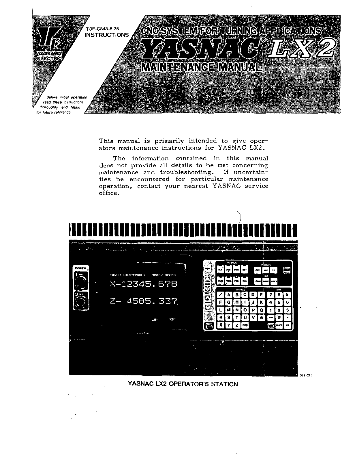
YASNAC
LX2
OPERATOR'S
--
7?
STATION
-
2
•!
:!
•
S82-215
Page 2

i
i
;
!
i
Page 3
TABLE
CONTENTS
OF
1.
OUTUNE
1.1
COMPONENT
YASNAC
1.2
CONTROL
BLOCK
SYSTEM
MAINTENANCE
1.3
1.4
ROUTINE
2.
TROUBLESHOOTING
TROUBLE
2.
1
TROUBLESHOOTING
2.
2
CODES
TROUBLESHOOTING
2.
3
CODES
1
DIAGRAM
3
INSPECTION
ISOLATION
9
37
SUBJECT
ACGC
A
ACGC
ACGC
ADJUSTMENT
ADJUSTMENTS
Indication
Alarm
MAINTENANCE
Trouble
ARRANGEMENT
SYSTEM
OF
1
YASNAC
INSTRUMENTS
SCHEDULE
7
7
ALARM
BY
WITHOUT
Service
PROCEDURES
Activity
INSTALLATION
UPON
....
....
OF
CONTROL
4
4
ALARM
ACGC
2.
4
2.
SUPPLY
5
2.
STATUS
6
DIAGNOSTICS
ADJUSTMENTS
3.
1
ADJUSTMENT
3.
POWER
2
3.
CONNECTIONS
DISPLAYING
3.
3
PARAMETERS
APPENDIX
COMPENSATION
INDEX
MAINTENANCE
VOLTAGE
CHECK
DISPLAYBYON-LINE
FUNCTION
(DCN)
UPON
PROCEDURES
TRANSFORMER
59
WRITING
AND
60
STORED
LEADSCREW
79
CHAPTER
2
2
2
3
3
.
.
44
46
47
INSTALLATION
57
ERROR
SECTION
4.
2
2.
.
.
.
.
2.
4
.
1
2.
4.
3.
1
. .
.
57
PAGE
44
.44
44
57
57
BLOCK
B
Check
C
COMPONENT
Counteracting
Power
DC
D
DISPLAYING
Faults
F
List
L
M
N
O
P
of
List
List
of
List
of
MAINTENANCE
Nature
NC
Unit
Operating
Operations
OUTLINE
Outline
Parameter
Parameter
POWER
Punching-out
DIAGRAM
Supply
Power
ARRANGEMENT
Alarm
Supply
AND
displayed
not
of
Alarm
Codes
Parameter
Setting
Standard
Numbers
and
Circumstances
Check
Procedure
and
of
Displays
Data
Types
TRANSFORMER
of
YASNAC
OF
Voltage
Codes
Voltage
WRITING
Numbers
Input/Output
INSTRUMENTS
Programming
Display
by
to
ACGC
Display
Check
PARAMETERS
of
Checks
CONNECTIONS
Setting
Data
CONTROL
YASNAC
OF
Alarm
Signals
Trouble
Input/Output
and
Parameter
SYSTEM
CONTROL
Indication
’
Signals
'
’
Data
SYSTEM
...
... .
.
.
.
.
.
.
...
1
3
.3
.3
.
1.2
2.
...
.
.
. .
.
...
1.
2. 2.
2.5.2
3.3
.
5.1
1
2.4.
2. 2.
3.3.
3.
3.
2.6.3
1.3
2.
1.
2.
1.
2.
6.
2.
1.
2.6.
3.3.2
3.3.
3.
2
3.3.
2
3
1
. .
7
. .
6
. .
.
.
1
3
2
.
.
2
. .
1
.
1
.
.
.
5
.
2
1
2
2
2
2
2
1
2
2
2
2
1
2
3
3
3
3
. .
. .
.
3
46
1
28
47
60
45
10
67
.62
48
4
7
8
.48
7
1
47
60
60
.59
.
61
R
ROUTINE
INSPECTION
SCHEDULE
1
1.4
4
Page 4
INDEX
(Cont'd)
SUBJECT
Software
s
STATUS
STORED
SUPPLY
Tap
T
Tap
Tape
TROUBLE
TROUBLESHOOTING
TROUBLESHOOTING
TROUBLESHOOTING
Writing
W
Version
DISPLAY
LEADSCREW
VOLTAGE
Changing
Changing
Input
of
ISOLATION
Parameter
Indication
Control
on
on
Control
Setting
ON-LINE
BY
ERROR
CHECK
Data
BY
WITHOUT
Data
DIAGNOSTICS
COMPENSATION
Transformer
Transformer
Parameter
and
ALARM
CODES
ALARM
(2T)
CODES
FUNCTION
.
.
Data
.
. .
(DCN)
CHAPTER
2
2
APPENDIX
2
3
3
.
...
.
.
3
2
2
2
. .
.
.
2
3
SECTION
2.4.4
2.
6
2.
5
3.2.2
3.
2.
1
3.3.4
2.
1
2
2.
.
.
2.
3
3. 3.
3
PAGE
45
47
79
46
.
.
.
.
59
.59
.
.
61
7
7
9
37
60
ii
Page 5
1.
OUTLINE
The
simultaneously
lathe.
machining,
possible
display,
called
puter),
1
1.
CONTROL
:
.
YASNAC
When
ACGC
LX2
Emphasis
and
16-bit
by
control
the
instead
sophisticated
the
controlling
(Advanced
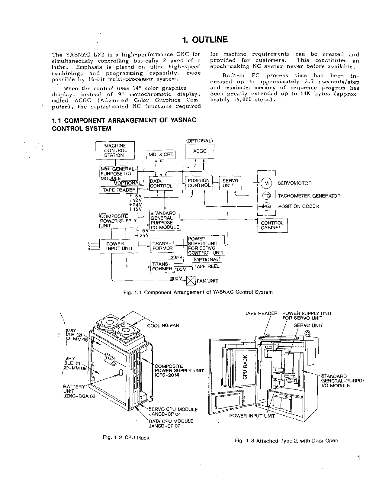
COMPONENT
SYSTEM
MACHINE
CONTROL
STATION
MINI
PURPOSE
MODULE
TAPE
COMPOSITE
POWER
UNIT
is
high-performance
a
is
programming
multi-processor
of
placed
14"
uses
monochromatic
9"
NC
basically
ultra
on
capability,
color
Color
functions
Graphics
ARRANGEMENT
MDI
GENERAL-
I/O
DATA
12
24
15
V
5
V
V
V
+
+
CONTROL
STANDARD
,
GENERAL-
PURPOSE
I/O
V
5
V
24
TRANS¬
FORMER
TRANS-
FORMER
READER
SUPPLY
_
POWER
INPUT
+
+
+
+
UNIT
2
axes
high-speed
system.
graphics
YASNAC
OF
CRT
&
T
MODULE
230
200
CNC
of
made
display,
Com¬
required
(OPTIONAL)
|
POSITION
CONTROL
.7
.
SUPPLY
V
-
1Q0V
—
V
for
a
ACGC
D
POWER
FOR
CONTROL
UNIT
SERVO
(OPTIONAL)
REEL~
|
TAPE
UNIT
FAN
for
machine
provided
epoch-making
Built-in
creased
and
been
imately
UNIT
up
maximum
greatly
16,000
SERVO
UNIT
requirements
for
customers.
NC
PC
to
memory
extended
steps).
1
system
process
approximately
CONTROL
CABINET
never
of
up
SERVOMOTOR
TACHOMETER
POSITION
can
This
time
2.7
sequence
64K
to
CODER
be
created
constitutes
before
available.
has
yseconds/step
program
bytes
GENERATOR
been
(approx¬
and
an
in¬
has
\
t
ORY
•
ULE
(2)\
p-MM
06
3RY
(ILE
(1)
.
MM
09~
N
02
ID-
/
BATTERYXE
UNIT
JZNC-GBA
Fig.
E2
1.
2
Fig.
hi
CPU
1.1
i
c
[L
C
Rack
Component
COOLING
COMPOSITE
POWER
(CPS-20N)
SERVO
JANCD-CP
CPU
DATA
JANCD-CP
Arrangement
FAN
SUPPLY
CPU
MODULE
04
MODULE
07
UNIT
YASNAC
of
I
POWER
Control
TAPE
CJ
<
a:
D.
o
Fig.
1.
System
READER
INPUT
3
Attached
j
/
LT0
E
UNIT
POWER
FOR
/
Type
SUPPLY
SERVO
SERVO
P)
2,
with
UNIT
UNIT
UNIT
STANDARD
GENERAL-PURPOf
I/O
MODULE
Open
Door
1
Page 6
1
1
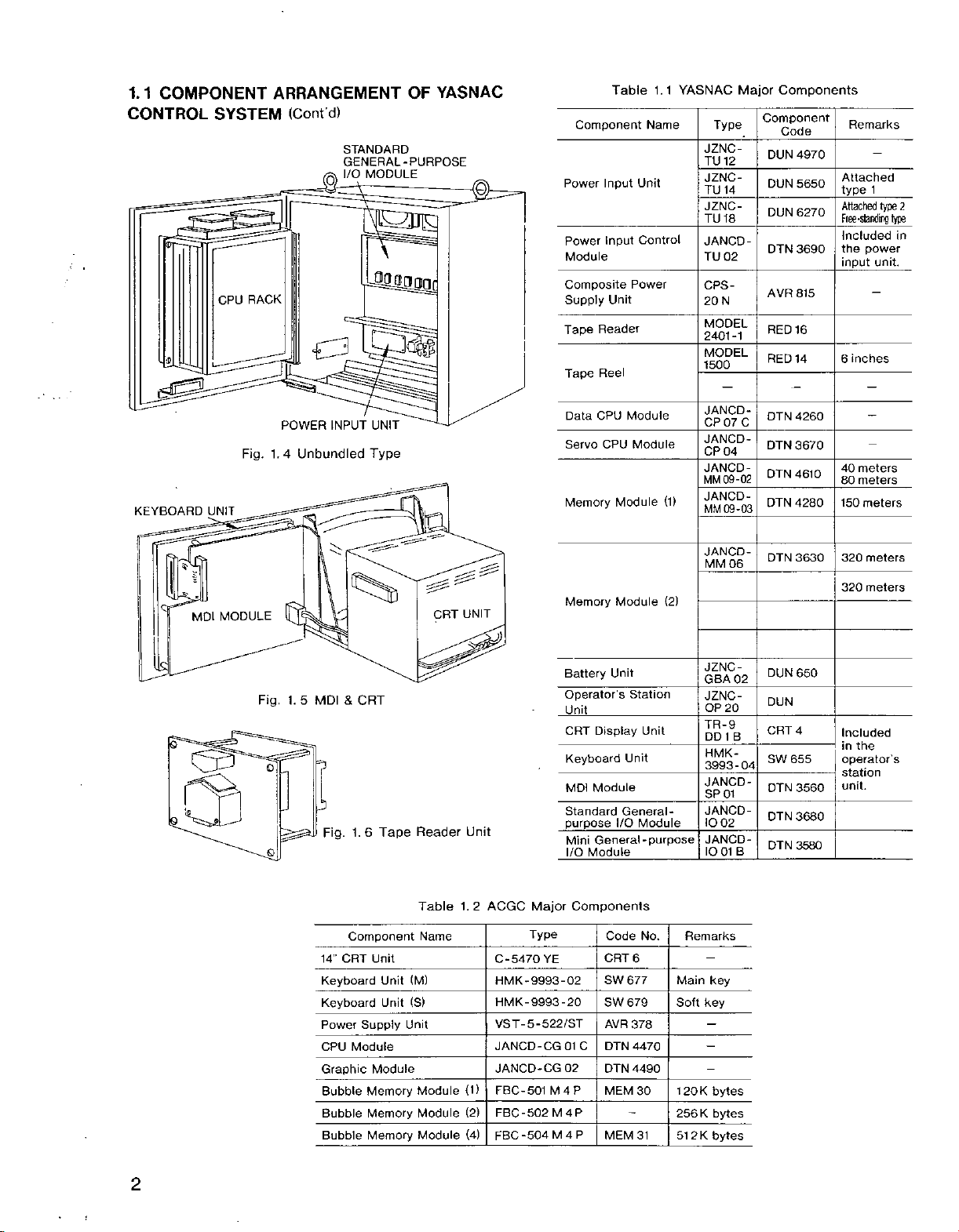
COMPONENT
CONTROL
$
efi3
KEYBOARD
SYSTEM
RACK
CPU
Fig.
UNIT
ARRANGEMENT
(Cont’d)
STANDARD
GENERAL-PURPOSE
MODULE
I/O
C3
POWER
1.4
Unbundled
INPUT
UNIT
Type
YASNAC
OF
o
Component
Power
Power
Module
Composite
Supply
Tape
Reader
Tape
Reel
CPU
Data
CPU
Servo
Memory
Table
Input
Input
Unit
Module
1.1
Name
Unit
Control
Power
Module
Module
YASNAC
(1)
Type
JZNC-
TU
12
JZNC-
TU
14
JZNC-
TU
18
JANCD-
TU
02
CPS-
N
20
MODEL
2401-1
MODEL
1500
JANCD-
CP07C
JANCD-
CP
04
JANCD-
09-02
MM
JANCD-
09-03
MM
Major
Components
Component
Code
DUN
4970
DUN
5650
DUN
6270
3690
DTN
AVR
815
16
RED
14
RED
4260
DTN
DTN
3670
DTN
4610
4280
DTN
Remarks
Attached
type
1
type
Attached
Ffee-standing
Included
power
the
input
unit.
inches
6
meters
40
meters
80
meters
150
2
type
in
Q|
JANCD-
06
MM
DTN
3630
I
Station
Unit
Unit
General
Module
No.
6
677
679
378
4470
4490
30
31
(2)
-
120K
256
Remarks
Main
Soft
K
51
2
K
JZNCGBA
02
JZNC-
OP
20
TR-9
DD1B
HMK-
3993-04
JANCDSP
01
JANCD-
IO
02
JANCD-
B
IO01
key
key
bytes
bytes
bytes
DUN
DUN
CRT
SW
OTN
DTN
DTN
650
4
655
3560
3680
3580
Battery
Operator’s
Standard
Major
Type
YE
5-522/ST
01
02
M4P
M4P
M4P
Memory
Unit
CRT
Keyboard
MDI
purpose
Mini
I/O
UNIT
Reader
Table
Name
(M)
(S)
Unit
Module
Module
Module
CRT
1.
Unit
2
(1)
(2)
(4)
ACGC
C-5470
HMK-9993-02
HMK-9993-20
VST-
JANCD-CG
JANCD-CG
FBC-501
FBC-502
FBC-504
MODULE
MDI
Fig.
1.
Q
O
t®.
9
to
5
MDI
Fig.
CRT
14”
Keyboard
Keyboard
Power
CPU
Graphic
Bubble
Bubble
Bubble
&
CRT
Tape
1.6
Component
Unit
Unit
Unit
Supply
Module
Module
Memory
Memory
Memory
Module
Unit
_
Display
Module
I/O
General-purpose
Module
Components
Code
CRT
SW
SW
AVR
C
DTN
DTN
MEM
MEM
meters
320
meters
320
Included
in
the
operator’s
station
unit.
2
1
Page 7
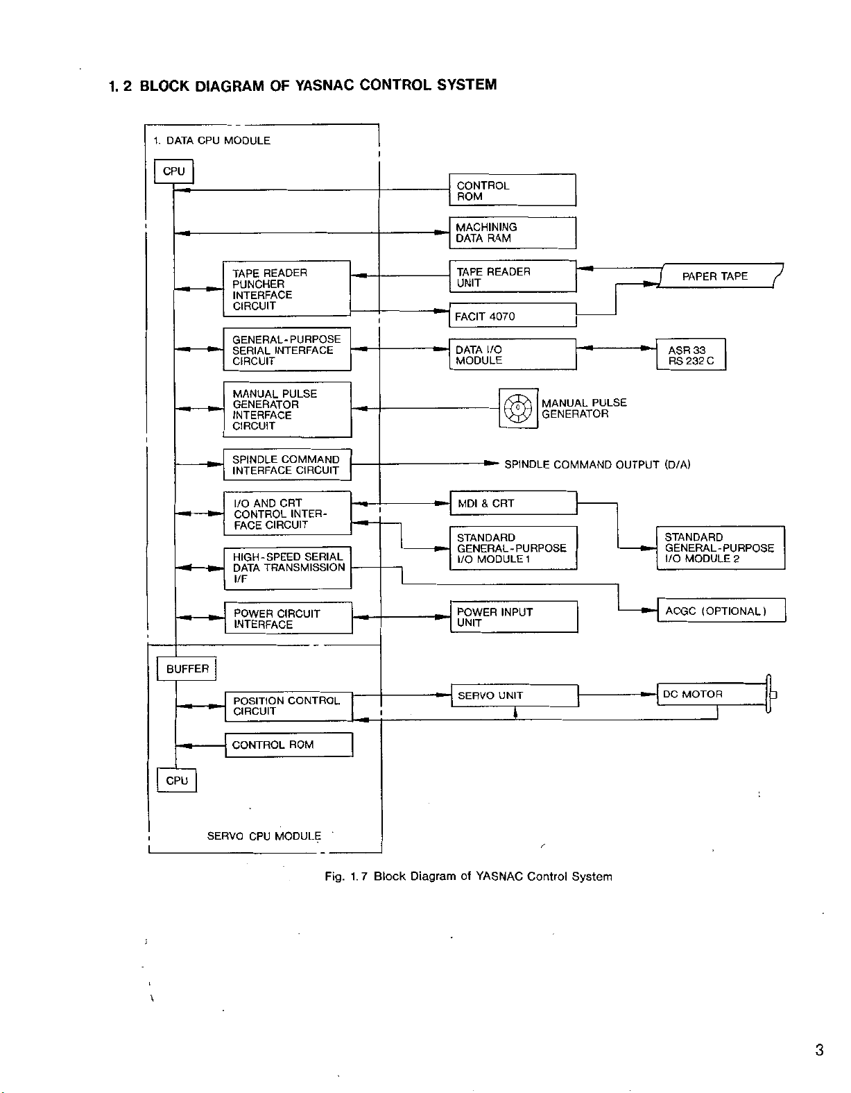
1.
2
BLOCK
DIAGRAM
YASNAC
OF
CONTROL
SYSTEM
1.
DATA
CPU
t
i
MODULE
CPU
READER
TAPE
PUNCHER
INTERFACE
CIRCUIT
GENERAL-PURPOSE
SERIAL
CIRCUIT
MANUAL
GENERATOR
INTERFACE
CIRCUIT
SPINDLE
INTERFACE
AND
I/O
CONTROL
CIRCUIT
FACE
HIGH-SPEED
TRANSMISSION
DATA
l/F
INTERFACE
PULSE
COMMAND
CIRCUIT
CRT
INTER¬
SERIAL
i
CONTROL
ROM
MACHINING
DATA
RAM
READER
TAPE
UNIT
4070
i
FACIT
I/O
DATA
MODULE
SPINDLE
-
&
MDI
CRT
STANDARD
GENERAL-PURPOSE
MODULE
I/O
1
1
J
MANUAL
GENERATOR
PULSE
COMMAND
3
OUTPUT
ASR
RS
(D/A)
STANDARD
GENERAL-PURPOSE
I/O
PAPER
33
C
232
MODULE
TAPE
2
7
i
L
\
\
BUFFER
CPU
POWER
INTERFACE
POSITION
CIRCUIT
CONTROL
SERVO
CPU
CIRCUIT
CONTROL
ROM
MODULE
Fig.
(OPTIONAL)
POWER
UNIT
SERVO
INPUT
UNIT
ACGC
DC
MOTOR
D
I
Block
Diagram
7
1.
YASNAC
of
Control
System
3
Page 8
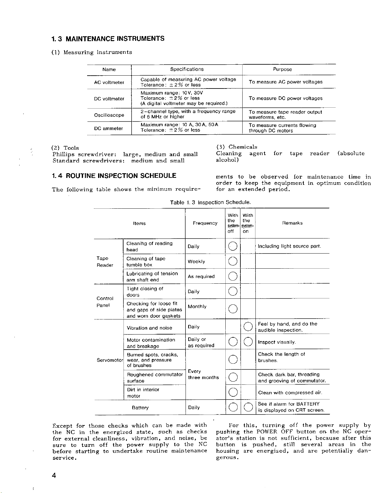
MAINTENANCE
1.
3
INSTRUMENTS
(1)
Measuring
(2)
Tools
Phillips
Standard
1.
4
ROUTINE
following
The
instruments
AC
DC
Oscilloscope
DC
screwdriver:
screwdrivers:
INSPECTION
table
Name
voltmeter
voltmeter
ammeter
shows
large,
medium
the
Items
Specifications
MHz
and
measuring
of
±2%
range:
±2%
voltmeter
type,
higher
or
range:
±2%
and
small
Capable
Tolerance:
Maximum
Tolerance:
digital
(A
2-channel
of
5
Maximum
Tolerance:
medium
SCHEDULE
minimum
Table
or
10V,
or
may
with
10A,30
or
small
require-
1.
power
AC
less
30V
less
be
frequency
a
A,
less
Inspection
3
Frequency
voltage
required.)
50A
(3)
Cleaning
alcohol)
ments
order
for
range
Chemicals
to
an
Schedule.
With With
the
system-
off
To
To
To
waveforms,
To
through
agent
to
be
keep
extended
the
system-
on
measure
measure
measure
measure
DC
observed
the
period.
Purpose
power
AC
power
DC
tape
reader
etc.
currents
motors
for
tape
equipment
Remarks
voltages
voltages
flowing
for
output
reader
maintenance
in
optimum
(absolute
time
condition
in
Except
the
external
for
sure
before
service.
NC
for
in
to
starting
those
the
turn
Tape
Reader
Control
Panel
Servomotor
checks
energized
cleanliness,
off
to
Cleanihgofreading
head
Cleaning
tumble
Lubricating
arm
Tight
doors
Checking
and
and
Vibration
Motor
and
Burned
wear,
of
brushes
Roughened
surface
Dirt
motor
Battery
which
state,
vibration,
the
power
undertake
tape
of
box
of
end
shaft
closing
for
gaps
of
side
worn
door
and
contamination
breakage
spots,
pressure
and
commutator
interior
in
can
supply
routine
tension
of
loose
gaskets
noise
_
cracks,
be
such
and
fit
plates
made
as
noise,
the
to
maintenance
Daily
Weekly
required
As
Daily
Monthly
Daily
Daily
required
as
Every
three
Daily
with
checks
or
months
be
NC
O
o
o
o
O
o
O
o
o
O
For
pushing
ator's
button
housing
gerous.
o
o
o
this,
the
station
is
are
Including
Feel
audible
Inspect
Check
brushes.
Check
and
Clean
See
displayed
is
turning
POWER
is
pushed,
energized,
hand,
by
inspection.
visually.
the
dark
grooving
with
if
alarm
not
light
source
and
length
threading
bar,
commutator.
of
compressed
for
BATTERY
CRT
on
off
OFF
button
sufficient,
still
and
part.
the
do
of
screen.
the
several
are
air.
power
on.
because
areas
potentially
the
supply
NC
after
in
by
oper¬
this
the
dan¬
4
;
Page 9
1.
(1)
(a)
with
with
soft
tape
4.
1
Cleaning
Remove
TAPE
a
oil
cloth
guide
READER
blower
or
with
and
the
tape
oily
tape
rubbish
brush.
dust,
absolute
the
tape
reader
If
wipe
alcohol.
retainer.
and
the
it
head
dust
using
glass
Also
(Daily)
from
is
a
the
stained
gauze
clean
glass
the
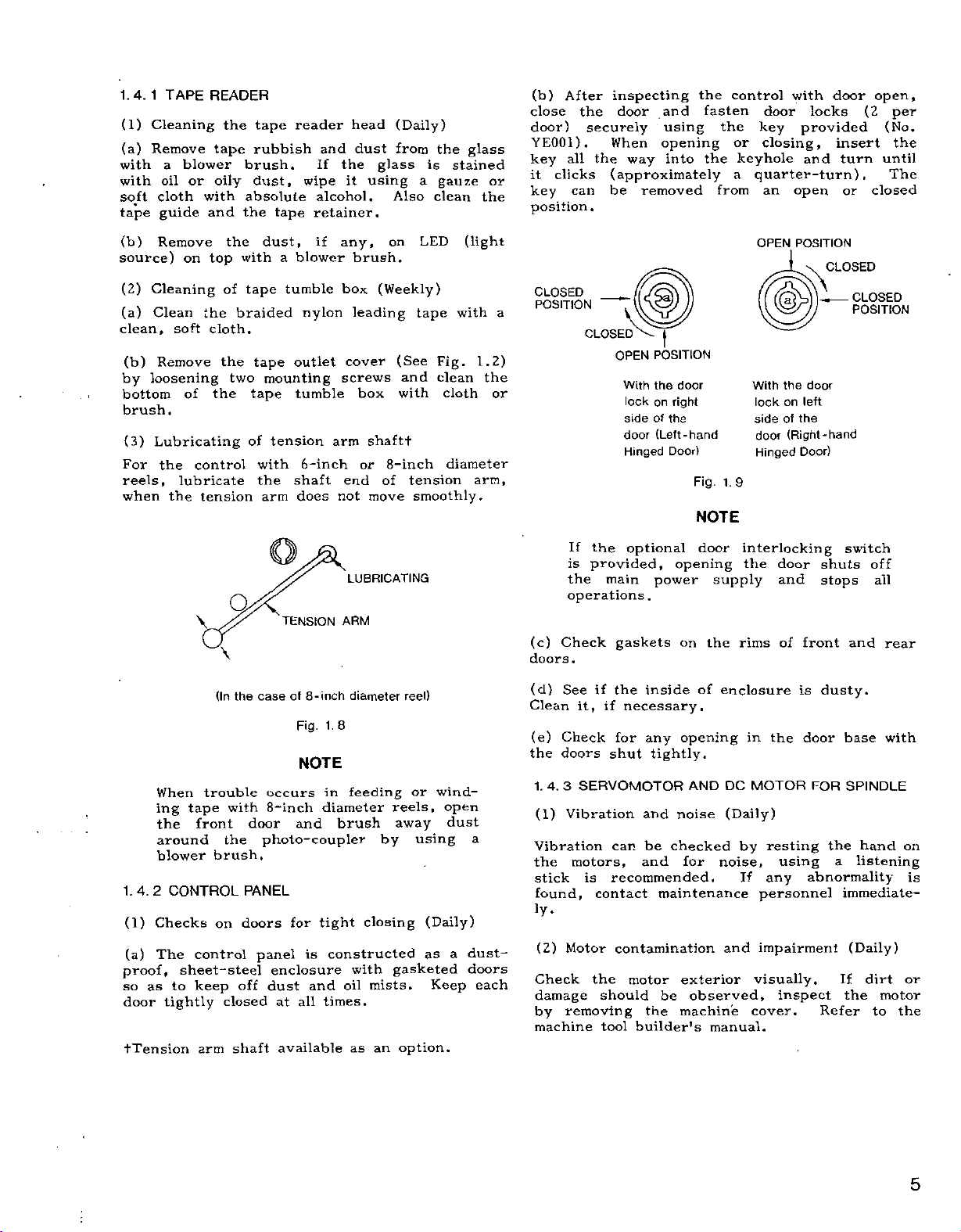
(b)
After
inspecting
door
all
clicks
can
the
securely
When
the
(approximately
be
close
door)
YE001).
key
it
or
key
way
removed
and
using
opening
into
the
fasten
the
from
control
the
key
or
closing,
keyhole
a
quarter-turn).
an
door
with
locks
provided
and
open
door
insert
turn
or
open,
(2
closed
per
(No.
the
until
The
position.
(b)
source)
(2)
Cleaning
(a)
Clean
clean,
(b)
loosening
by
bottom
brush.
(3)
For
reels,
when
1.4.
2
(1)
(a)
proof,
so
as
door
tTension
Remove
on
top
the
soft
cloth.
Remove
of
Lubricating
control
the
lubricate
the
tension
v
When
ing
the
around
blower
Checks
The
trouble
tape
front
CONTROL
control
sheet-steel
to
keep
tightly
arm
the
of
the
the
Q
\
(In
with
the
brush,
on
closed
dust,
with
tape
braided
tape
two
mounting
tape
of
with
the
arm
case
the
occurs
8-inch
door
photo-coupler
PANEL
doors
panel
off
dust
shaft
a
blower
tumble
nylon
outlet
tumble
tension
6-inch
shaft
does
TENSION
-inch
of
8
Fig.
NOTE
and
for
is
enclosure
and
all
at
available
if
any,
brush.
box
leading
cover
screws
box
arm
or
end
not
LUBRICATING
ARM
diameter
1.
8
feeding
in
diameter
brush
tight
constructed
with
oil
times.
as
on
(Weekly)
(See
with
shaftt
8-inch
of
move
reels,
away
by
closing
gasketed
mists.
option.
an
LED
tape
and
tension
smoothly.
reel)
or
using
(Daily)
as
Keep
(light
with
Fig.
clean
cloth
diameter
wind¬
open
dust
a
1.2)
the
arm,
a
dustdoors
each
a
or
CLOSED
POSITION
If
is
the
operations.
(c)
Check
doors
.
(d)
See
Clean
(e)
Check
the
doors
1.
4.
3
(1)
Vibration
Vibration
motors,
the
stick
found,
iy.
(2)
Motor
Check
damage
by
removing
machine
H
CLOSED
POSITION
OPEN
With
the
on
lock
of
side
(Left-hand
door
Hinged
the
optional
provided,
main
if
it,
if
SERVOMOTOR
is
contact
the
should
tool
power
gaskets
the
inside
necessary.
for
any
shut
tightly.
and
be
can
and
recommended.
maintenance
contamination
motor
be
the
builder's
door
right
the
Door)
Fig.
NOTE
door
opening
on
of
opening
AND
noise
checked
for
exterior
observed,
machine
1.9
supply
the
enclosure
DC
(Daily)
noise,
and
manual.
OPEN
POSITION
©
With
the
on
lock
the
side
of
(Right-hand
door
Hinged
interlocking
the
door
and
of
rims
is
in
the
MOTOR
by
resting
using
If
any
personnel
impairment
visually.
inspect
cover.
CLOSED
U
CLOSED
—
POSITION
door
left
Door)
switch
shuts
stops
front
and
dusty.
door
base
FOR
SPINDLE
the
a
abnormality
immediate-
(Daily)
If
the
Refer
off
all
rear
with
hand
listening
dirt
motor
to
on
is
or
the
5
Page 10
1.
4.
3
SERVOMOTOR
(Cont'd)
(3)
Carbon
carbon
The
around
cause
armature
the
avoid
commutators
months.
Double
turning
before
the
motor
and
worst
this,
check
off
inspecting
(Disconnecting
supply
off
cause
(a)
wears
If
contaminated
power
Under
wear
unit
fatal
by
is
overcurrent
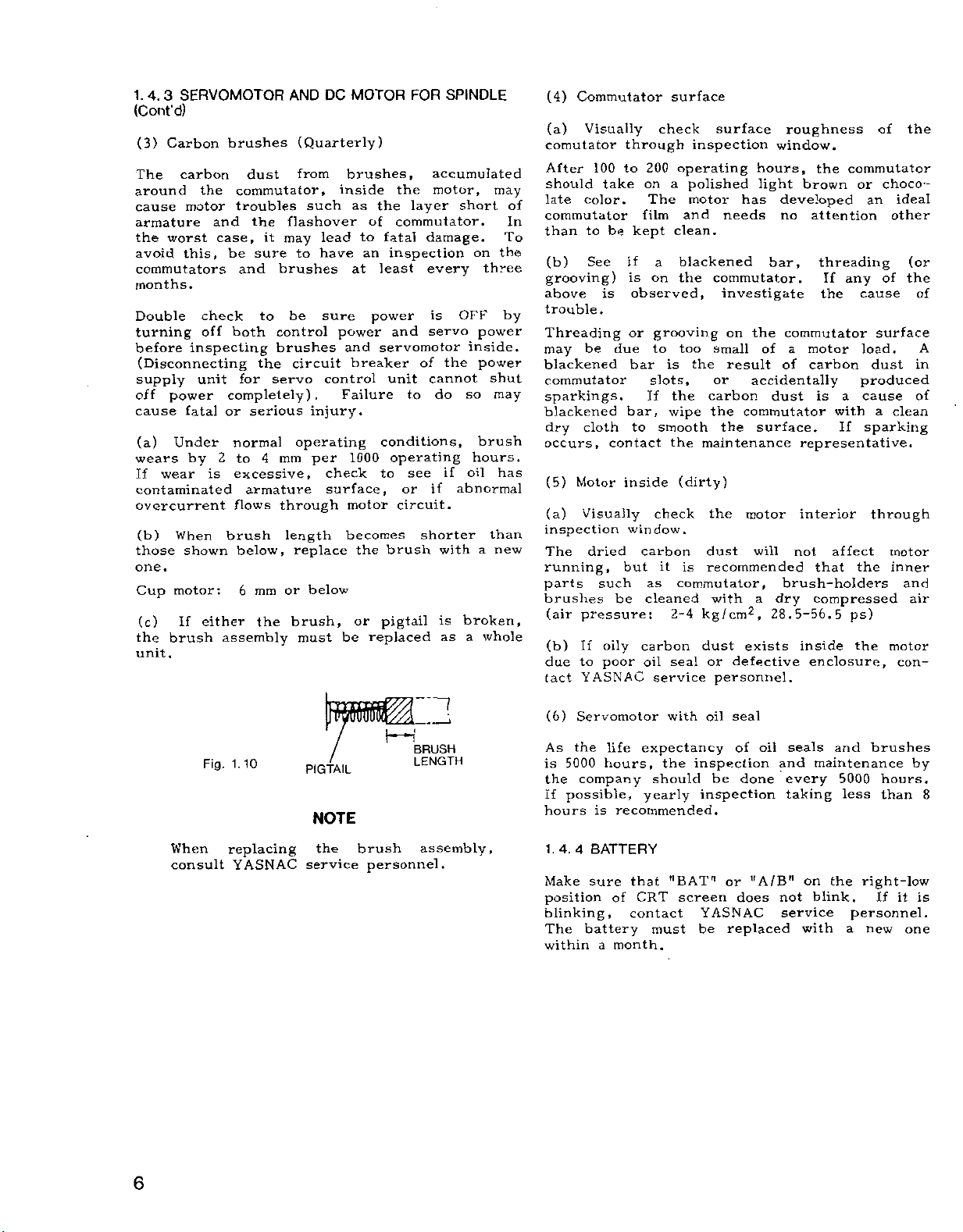
(b)
When
those
shown
one.
motor:
Cup
(c)
If
either
the
brush
unit.
brushes
dust
commutator,
troubles
the
case,
be
it
sure
and
to
both
the
servo
for
completely).
or
serious
normal
4
to
2
excessive,
armature
flows
brush
below,
mm
6
the
assembly
AND
(Quarterly)
from
such
flashover
may
to
brushes
be
control
brushes
circuit
operating
mm
through
length
replace
or
brush,
must
DC
lead
have
sure
control
injury.
per
check
surface,
below
MOTOR
brushes,
inside
as
of
to
an
at
power
power
and
breaker
Failure
1000
motor
becomes
the
or
be
replaced
FOR
accumulated
motor,
the
layer
the
commutator.
fatal
damage.
inspection
and
every
is
servo
least
servomotor
of
cannot
unit
to
conditions,
operating
see
to
or
if
circuit.
shorter
brush
pigtail
SPINDLE
short
on
OFF
inside.
the
so
do
hours.
oil
if
abnormal
with
broken,
is
as
a
may
To
the
three
by
power
power
shut
may
brush
has
than
new
a
whole
of
In
(4)
Commutator
(a)
Visually
comutator
After
should
late
100
take
color.
commutator
to
than
(b)
See
grooving)
above
trouble.
Threading
may
blackened
commutator
sparkings.
blackened
dry
occurs,
(5)
(a)
inspection
The
running,
parts
brushes
(air
(b)
due
tact
is
be
cloth
Motor
Visually
dried
such
pressure:
If
oily
to
poor
YASNAC
through
to
be
kept
if
is
observed,
or
due
bar
bar,
to
contact
inside
window.
but
be
check
200
on
The
film
a
on
grooving
to
is
slots,
If
smooth
check
carbon
it
as
cleaned
carbon
oil
service
surface
surface
inspection
operating
polished
a
motor
and
clean.
blackened
the
commutator.
investigate
too
small
the
or
the
carbon
the
wipe
the
the
maintenance
(dirty)
the
dust
is
recommended
commutator,
with
kg/cm2,
2-4
dust
or
seal
personnel.
hours,
light
has
needs
the
on
of
result
accidentally
commutator
surface.
motor
will
a
exists
defective
roughness
window.
the
brown
developed
no
attention
bar,
threading
If
the
commutator
motor
a
of
carbon
is
dust
representative.
interior
not
that
brush-holders
compressed
dry
28.5-56.5
inside
enclosure,
commutator
or
an
any
cause
load.
dust
produced
a
cause
with
If
sparking
through
affect
the
ps)
the
of
choco¬
ideal
other
of
surface
clean
a
motor
inner
and
motor
con¬
the
(or
the
of
A
in
of
air
When
consult
Fig.
1.10
replacing
YASNAC
PIGTAIL
NOTE
the
service
brush
personnel.
1
---
BRUSH
LENGTH
assembly,
(6)
Servomotor
the
As
is
5000
company
the
If
possible,
hours
1.4.4
Make
position
blinking,
The
within
battery
life
expectancy
hours,
is
yearly
recommended.
BATTERY
sure
that
CRT
of
contact
a
month.
with
the
should
"BAT"
must
inspection
inspection
screen
YASNAC
be
oil
be
or
seal
oil
of
done
"A/B"
does
replaced
seals
and
every
taking
on
not
service
with
and
brushes
maintenance
5000
less
the
right-low
blink.
personnel.
new
a
hours.
than
If
by
8
is
it
one
6
Page 11
2.
TROUBLESHOOTING
2.
Try
the
lating
service
ble.
;
1
'
:
1
!
-i
1
the
2.
(1)
•
•
•
•
•
•
•
•
•
•
•
(2)
•
•
(3)
>
i
t
:
i
1
TROUBLE
to
fully
trouble
the
personnel
Verifying
down
1
NATURE
1.
Type
In
what
In
what
operate?
What
was
trouble
the
Was
positioning
the
Was
the
Was
Was
an
What
was
which
In
was
the
Does
the
the
the
trouble
trouble
Is
Is
Frequency
When
when
How
Run
did
other
often
Recurrence
the
trouble
NC
unit
programmed.
sxternal
/erify
ributed
ncrease
sk
the
ider
which
ISOLATION
analyze
occurred.
trouble
the
of
AND
trouble
did
mode(s)
the
positioning
error,
path
the
alarm
program
trouble
of
the
machines
did
of
program
and
offset
values
or
decrease
operator
the
your
display
related
associated
trouble
it
compare
time
of
mode
occurred?
tool
feedrate
auxiliary
sequence
several
disturbances?
the
the
circumstances
and/or
called
following
This
in
for
necessary
is
having
to
points
correct
system:
CIRCUMSTANCES
the
does
displayed
erroneous
correct?
function
number?
did
trouble
of
incorrect
the
occur?
the
MDI
position
(by
used?
trouble
number?
a
in
recur
particular
to
tool
with
changing?
trouble
develop?
in
were
operation?)
occur?
trouble
that
tape
the
values
to
Check
them
trouble
stored.
the
explain
occurred.
with
and
override
the
times.
Is
being
trouble
the
the
will
TROUBLE
OF
system
CRT
&
(error
values)?
much)?
how
occur?
feedrate?
(Did
experienced
the
values
those
attributable
remaining
value.
circumstances
which
in
for
iso¬
YASNAC
trou¬
minimize
normally
when
axis,
What
mode?
occur
it
in
being
dis-
the
the
the
recent
AND
PROGRAMMING
properly
change
well
trained?
of
familiar
operators?
with
CHECKS
pro¬
the
2.
(1)
•
*
1.2
Was
Was
Was
OPERATIONS
Operations
operator
the
there
a
the
operator
gram?
•
Was
•
Was
absolute
•
Was
•
Can
•
Was
the
the
the
other
the
program
program
command?
compensation
tool
operating
optional
interrupted
placed
modes
block
under
properly
skip
before
be
incremental
selected?
function
completion?
or
set?
properly
used?
•
•
•
Was
Was
Were
the
the
there
tape
program
any
correctly
properly
inadvertent
set?
coded?
or
erroneous
oper¬
ations?
(2)
•
•
•
•
Punched
Was
Was
Were
Was
the
the
the
tapes
tape
tape
tape
properly
program
contaminated?
or
bent
crimpled?
spliced?
successfully
run
prior
to
this
operation?
•
Was
the
tape
correctly
•
Was
the
tape
puncher
•
Was
(3)
•
Is
•
Was
instruction
•
Did
•
Did
to
Was
black
a
Programming
the
program
program
the
trouble
the
trouble
the
a
check
tape
new?
manual?
occur
occur
list
operating
used?
formulated
in
in
made
punched?
a
particular
subprogram?
a
used
and
normally?
according
for
block?
tape
to
the
veri¬
fication?
(4)
Settings
or
•
•
Were
made
Was
a
there
prior
fuse
any
to
starting
blown?
corrections
the
operation?
adjustments
:
?
j
7
:
i
Page 12
1.
2
2.
(Cont'd)
•
Was
•
Was
Was
•
What
•
Was
board)
•
Was
•
Was
•
Was
Was
(5)
External
*
Was
justed?
•
Was
adjusted?
•
Was
•
Is
frequency
machine,
range?
•
Was
nearby?
•
Is
similar
Has
inside
•
Has
this
(6)
Ambient
•
What
•
Was
•
Was
•
Was
the
•
Where
•
Was
2.
1.3
(1)
Control
Was
•
Was
OPERATIONS
an
emergency
machine
the
alarm
an
the
was
the
alarm
?
MODE
the
the
override
the
machine
the
feed
factors
the
machine
control
the
NC
the
there
there
there
the
the
unit?
was
there
the
there
immediate
the
NC
the
the
any
any
failures
user
the
same
tape
there
system
UNIT
MDI
tape
unit
sewing
welding
any
NC
conditions
the
any
any
any
CHECK
unit
AND
PROGRAMMING
stop
tool
ready
effect?
in
state
number?
alarm
lit
lamp
set
lock
in
to
set?
set?
switch
hold
tool
cabinet
recently
source
noise
machine,
machine)
machine
new
in
made
NC
your
an
other
unit?
trouble
temperature?
abrupt
oil
or
contaminated?
cutting
reader
area?
vibrations?
exposed
exterior
CRT
&
reader
unit
kept
maintained?
to
module
on
a
normal
11
0"?
recently
recently
repaired
(e.g.,
electrical
within
unit
factory?
attempt
occured
change
to
the
normal?
clean?
operate?
position?
repaired
recently
that
at
previously
in
temperature?
fluid
direct
CHECKS
(on
repaired
adjusted?
or
crane,
discharge
interference
has
developed
adjustments
splashed,
sunlight?
printed
or
high-
installed
with
ad¬
or
•
Was
•
Was
•
Did
interior?
(2)
Was
What
from
(3)
•
Was
•
Was
the
normal?
Was
(4)
•
Was
•
Were
+24
•
Was
•
Was
•
Was
•
Was
*
Was
Tape
Control
Composite
the
the
any
the
the
the
the
air
the
the
V)?
each
a
the
the
the
were
)
the
fuse
tape
unit
machining
reader
tape
the
tape
unit
control
fan
flow
interior
input
output
voltage
circuit
shield
wiring
reader
operated
reader
characteristics
reader?
interior
unit
motor
from
damaged
power
voltage
blown?
breaker
properly
door
with
chips
contaminated?
interior
operating
cooling
the
supply
normal?
voltage
within
properly
closed?
its
enter
of
contaminated?
corrosive
by
unit
normal
tolerance?
tripped?
grounded?
inside
door
open?
the
the
normally?
air
exhaust
(+5V,
the
cabinet
waveforms
(Was
port
gas?
±12
control
V,
cabinet?
•
•
How
Was
much
there
did
any
the
input
significant
voltage
drop
fluctuate?
in
input
volt¬
age?
(e.g.,
machine)?
inserted?
(with
a
door
large
weld¬
•
Was
interlock
•
Is
amount
ing
(5)
Grounding
•
•
(6)
•
•
Was
Was
Cables
Were
Was
in
Was
•
Was
the
there
of
machine,
grounding
the
shield
cable
any
internal
any
external
any
front
in
cable
effect)?
machine
any
current
electrical
connectors
broken
or
rear
in
properly
grounding
cable
cable
door
that
the
factory
discharge
connected?
proper?
securely
damaged?
damaged?
contaminated?
or
open
consumes
8
Page 13
(7)
•
•
•
•
Modules
Were
Were
What
Were
ules
(on
modules
all
connectors
plug
the
was
connections
correct?
printed
securely
revision
(on
circuit
installed?
properly
letter?
cable)
flat
board)
secured?
between
mod¬
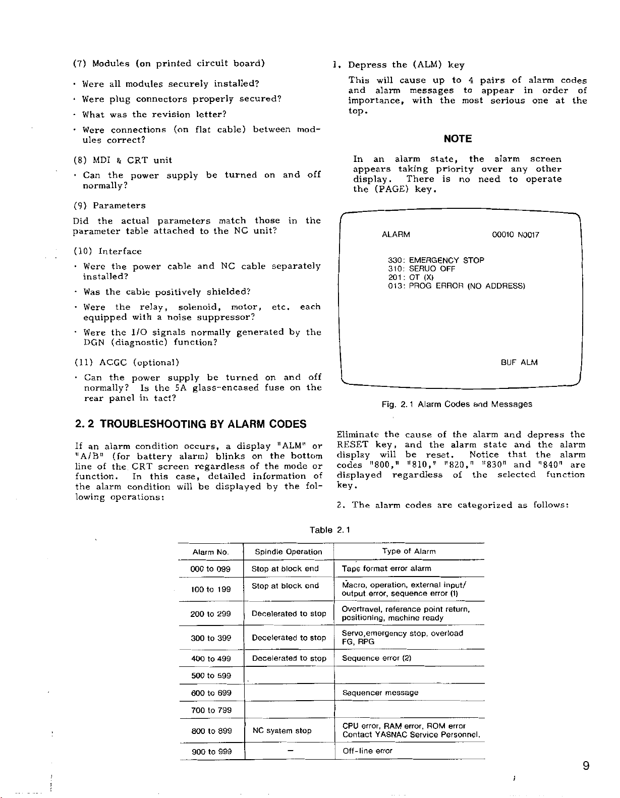
Depress
1.
This
and
importance,
top.
will
alarm
the
cause
(ALM)
up
messages
with
key
to
the
NOTE
4
to
most
pairs
appear
serious
of
alarm
in
one
order
codes
at
of
the
(8)
•
Can
MDI
the
&
CRT
power
unit
normally?
(9)
Parameters
Did
the
parameter
(10)
Interface
•
Were
actual
table
the
parameters
attached
power
installed?
Was
•
Were
equipped
Were
DGN
(11)
•
Can
normally?
rear
2.
2
an
If
"A/B"
line
function.
the
lowing
cable
the
the
positively
relay,
withanoise
the
I/O
signals
(diagnostic)
ACGC
the
panel
(optional)
power
Is
the
tact?
in
TROUBLESHOOTING
alarm
of
alarm
condition
(for
battery
CRT
the.
In
condition
operations:
screen
this
supply
cable
solenoid,
function?
supply
5A
occurs,
alarm)
case,
will
be
turned
match
the
NC
NC
to
and
shielded?
motor,
suppressor?
normally
be
turned
glass-encased
ALARM
BY
a
blinks
regardless
detailed
displayed
be
on
those
unit?
cable
generated
on
fuse
display
on
of
the
information
and
in
separately
etc.
by
and
on
CODES
"ALM"
bottom
the
mode
the
by
off
the
each
the
off
the
fol¬
or
or
of
In
appears
display.
the
Eliminate
RESET
display
codes
displayed
.
key
The
2.
an
(PAGE)
ALARM
Fig.
the
key,
will
"800,"
alarm
alarm
taking
There
EMERGENCY
330:
310:
SERUO
:
201
OT
PROG
013:
1
2.
cause
and
be
"810,"
regardless
codes
key.
(X)
Alarm
reset.
state,
priority
is
OFF
ERROR
of
the
are
no
STOP
Codes
the
alarm
"820,"
of
categorized
the
over
need
(NO
and
alarm
Notice
"830"
the
alarm
00010
ADDRESS)
BUF
Messages
and
state
selected
any
to
that
N0017
ALM
and
and
as
screen
other
operate
depress
the
the
"840"
function
follows:
the
alarm
alarm
are
Alarm
000
100
200
300
400
500
600
700
800
900
2.
Table
No.
to
099
199
to
299
to
to
399
499
to
599
to
to
699
to
799
to
899
to
999
Spindle
Stop
Stop
Decelerated
Decelerated
Decelerated
NC
block
at
block
at
system
Operation
end
end
to
to
to
stop
stop
stop
stop
1
Tape
format
Macro,
output
error,
Overtravel,
positioning,
emergency
Servo,
FG,
RPG
Sequence
Sequencer
error,
CPU
Contact
Off-line
Type
error
operation,
sequence
reference
machine
error
message
RAM
YASNAC
error
of
alarm
external
stop,
(2)
error,
Service
Alarm
point
ready
ROM
input/
error
return,
overload
error
Personnel.
(1)
9
)
Page 14
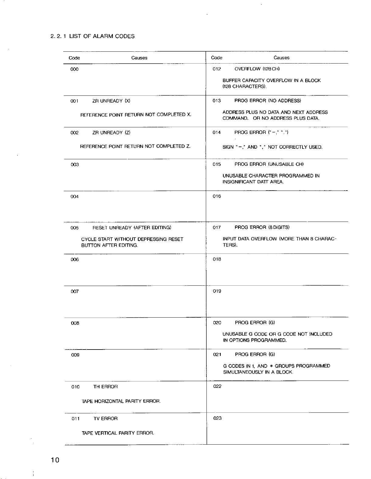
2.
LIST
2.
1
OF
ALARM
CODES
Code
000
001
REFERENCE
002
REFERENCE
003
004
005
UNREADY
ZR
UNREADY
ZR
RESET
(X)
RETURN
POINT
(Z)
RETURN
POINT
UNREADY
Causes
(AFTER
COMPLETED
NOT
COMPLETED
NOT
EDITING)
Code
012
013
X.
014
Z.
015
OVERFLOW
BUFFER
(128
CAPACITY
CHARACTERS).
PROG
ADDRESS
COMMAND.
PROG
SIGN
PROG
UNUSABLE
ERROR
PLUS
ORNOADDRESS
ERROR
AND
ERROR
CHARACTER
INSIGNIFICANT
016
ERROR
017
PROG
(128
CH)
OVERFLOW
(NO
NO
DATA
NOT
V
(UNUSABLE
AREA.
DATT
(8
Causes
IN
ADDRESS)
AND
NEXT
PLUS
V’)
CORRECTLY
CH)
PROGRAMMED
DIGITS)
A
BLOCK
ADDRESS
DATA.
USED.
IN
006
007
008
009
010
CYCLE
BUTTON
TH
HORIZONTAL
TAPE
START
AFTER
ERROR
WITHOUT
EDITING.
PARITY
DEPRESSING
ERROR.
RESET
INPUT
DATA
TERS).
018
019
020
PROG
UNUSABLE
IN
OPTIONS
G
PROG
CODES
021
SIMULTANEOUSLY
022
OVERFLOW
ERROR
G
(G)
CODEORG
PROGRAMMED.
1,
AND
IN
(G)
*
A
ERROR
IN
(MORE
CODE
GROUPS
BLOCK.
CHARAC¬
8
THAN
NOT
INCLUDED
PROGRAMMED
011
TAPE
TV
ERROR
VERTICAL
PARITY
ERROR.
023
10
:
i
Page 15
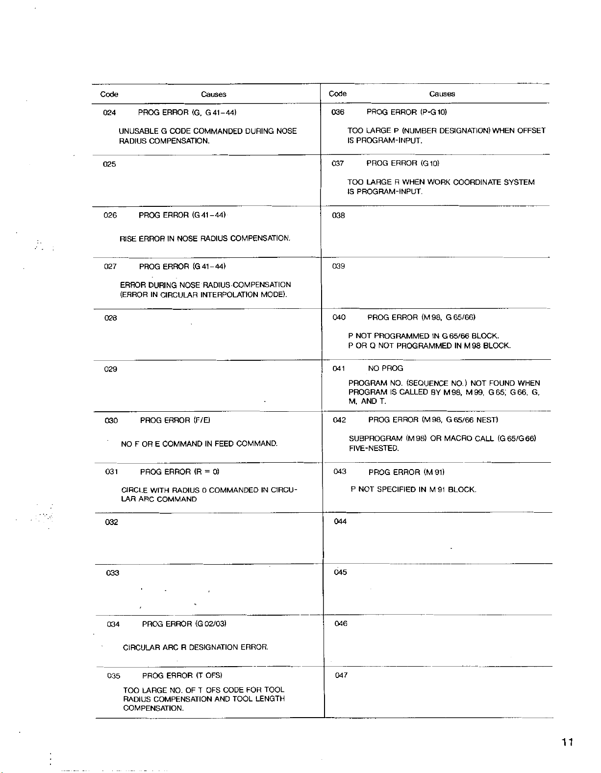
Code
024
PROG
ERROR
(G,
Causes
G41-44)
Code
036
PROG
ERROR
(P-G
Causes
10)
UNUSABLE
RADIUS
025
026
RISE
027
ERROR
(ERROR
028
029
CODE
G
COMPENSATION.
PROG
ERROR
IN
ERROR
DURING
CIRCULAR
IN
NOSE
NOSE
ERROR
PROG
COMMANDED
(G41-44)
RADIUS
(G41-44)
COMPENSATION.
RADIUS
COMPENSATION
INTERPOLATION
DURING
MODE).
NOSE
TOO
LARGE
PROGRAM-INPUT.
IS
037
PROG
LARGE
TOO
PROGRAM-INPUT.
IS
038
039
P
P
NOT
OR
PROG
Q
NO
040
041
PROGRAM
PROGRAM
M,
AND
(NUMBER
P
WHEN
R
ERROR
(G10)
<M98t
ERROR
PROGRAMMED
NOT
PROGRAMMED
PROG
(SEQUENCE
NO.
CALLED
IS
T.
DESIGNATION)
COORDINATE
WORK
65/66)
G
IN
G
65/66
IN
NO.)
M98, M99,
BY
BLOCK.
M98
NOT
WHEN
SYSTEM
BLOCK.
FOUND
G65;
OFFSET
WHEN
G66,
G,
030
PROG
NOFOR
031
PROG
CIRCLE
LAR
ARC
032
033
034
035
PROG
CIRCULAR
PROG
TOO
LARGE
RADIUS
COMPENSATION.
(F/E)
ERROR
COMMAND
E
ERROR
WITH
RADIUS
COMMAND
ERROR
ARC
ERROR
NO.
IN
(R=0)
0
02/03)
(G
DESIGNATION
R
OFS)
(T
OF
T
OFS
COMPENSATION
COMMAND.
FEED
COMMANDED
ERROR.
FOR
CODE
TOOL
AND
IN
CIRCU¬
TOOL
LENGTH
042
SUBPROGRAM
FIVE-NESTED.
043
P
NOT
044
045
046
047
PROG
ERROR
ERROR
PROG
SPECIFIED
(M98)
IN
(M
(M
98r
OR
M
91)
91
G
65/66
MACRO
BLOCK.
NEST)
CALL
(G65/G66)
11
Page 16
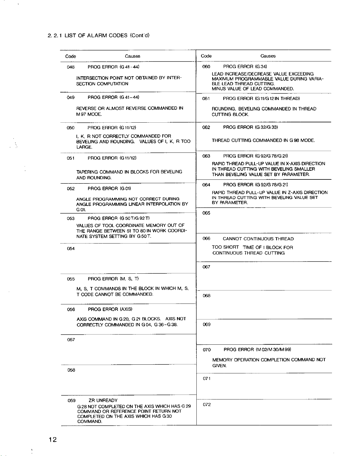
2. 2.
1
LIST
OF
ALARM
CODES
(Cont’d)
Code
048
049
PROG
INTERSECTION
SECTION
COMPUTATION
PROG
REVERSEORALMOST
MODE.
97
M
050
051
052
053
054
PROG
I,
K,
NOT
R
BEVELING
LARGE.
PROG
TAPERING
ROUNDING.
AND
PROG
PROGRAMMING
ANGLE
PROGRAMMING
ANGLE
G
01.
PROG
VALUES
THE
NATE
OF
RANGE
SYSTEM
AND
COMMAND
Causes
(G41-44)
ERROR
NOT
POINT
(G41-44)
ERROR
REVERSE
/12)
(G
1
ERROR
CORRECTLY
1
COMMANDED
ROUNDING.
(G
ERROR
ERROR
ERROR
TOOL
BETWEEN
11/12)
IN
BLOCKS
(G
01)
NOT
LINEAR
(G
T/G
50
COORDINATE
51
SETTINGBYG50T.
OBTAINED
COMMANDED
VALUES
FOR
CORRECT
INTERPOLATION
92
T>
MEMORY
80
IN
WORK
TO
INTER¬
BY
FOR
K,
OF
lr
BEVELING
DURING
OUT
COORDI¬
R
IN
TOO
OF
BY
Code
060
LEAD
MAXIMUM
BLE
MINUS
061
ROUNDING,
CUTTING
062
THREAD
063
RAPID
IN
THAN
064
RAPID
IN
BY
065
066
TOO
CONTINUOUS
PROG
ERROR
<G
INCREASE/DECREASE
PROGRAMMABLE
LEAD
THREAD
VALUE
PROG
CUTTING.
OF
LEAD
ERROR
(G11/G12IN
BEVELING
BLOCK.
PROG
ERROR
CUTTING
PROG
ERROR
THREAD
THREAD
CUTTING
BEVELING
PROG
ERROR
THREAD
THREAD
CUTTING
PARAMETER.
CANNOT
SHORT
(G
COMMANDED
<G
PULL-UP
VALUE
(G
PULL-UP
CONTINUOUS
OF
TIME
THREAD
Causes
34)
VALUE
VALUE
COMMANDED.
THREAD)
COMMANDED
33)
32/G
78/G
VALUE
IN
BEVELING
BY
78/G
VALUE
BEVELING
THREAD
BLOCK
21)
PARAMETER.
21)
IN
92/G
WITH
SET
92/G
WITH
I
CUTTING
EXCEEDING
DURING
IN
THREAD
G98
MODE.
IN
X-AXIS
SMALLER
Z-AXIS
VALUE
FOR
VARIA¬
DIRECTION
DIRECTION
SET
055
M,
S,
T
CODE
056
AXIS
CORRECTLY
057
058
059
G28NOT
COMMAND
COMPLETED
COMMAND.
PROG
ERROR
COMMANDS
T
CANNOT
PROG
BE
ERROR
COMMANDING
COMMANDED
UNREADY
ZR
COMPLETED
REFERENCE
OR
THE
ON
T)
(M,
S,
BLOCK
IN
THE
COMMANDED.
(AXIS)
BLOCKS.
G
20,
21
G04,
IN
ON
AXIS
THE
POINT
WHICH
AXIS
WHICH
IN
AXIS
G36-G38.
WHICH
RETURN
G30
HAS
HAS
NOT
Mr
NOT
G
067
S,
068
069
30/M
99)
COMMAND
NOT
29
070
071
072
PROG
MEMORY
GIVEN.
ERROR
OPERATION
(M
02/M
COMPLETION
12
1
Page 17
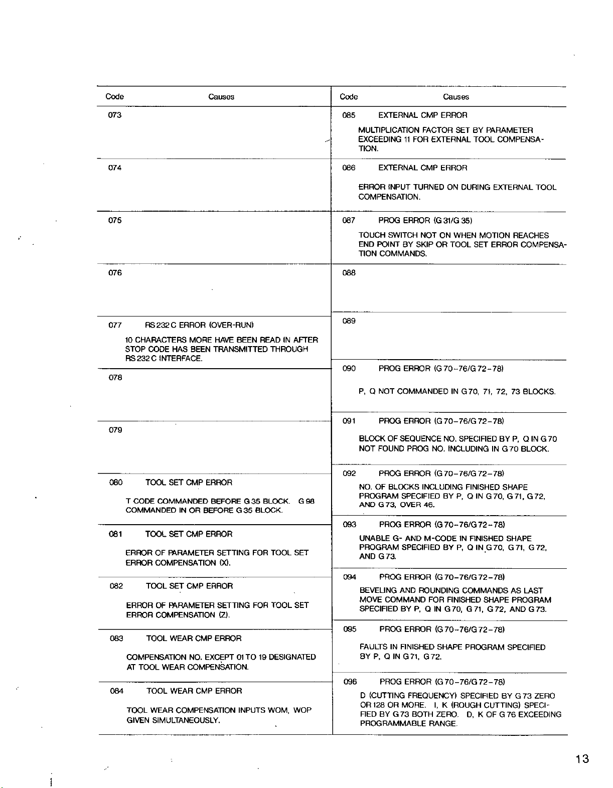
Code
073
Causes
Code
085
EXTERNAL
MULTIPLICATION
EXCEEDING
TION.
11
CMP
FACTOR
FOR
Causes
ERROR
SET
EXTERNAL
BY
PARAMETER
TOOL
COMPENSA¬
074
075
076
077
10
STOP
RS232C
078
079
RS232C
ERROR
CHARACTERS
CODE
HAS
INTERFACE.
(OVER-RUN)
HAVE
MORE
TRANSMITTED
BEEN
BEEN
READINAFTER
THROUGH
086
EXTERNAL
ERROR
INPUT
COMPENSATION.
087
088
089
090
091
PROG
TOUCH
END
POINT
TION
COMMANDS.
PROG
Q
P,
NOT
PROG
BLOCK
FOUND
NOT
SWITCH
OF
CMP
ERROR
TURNED
ERROR
BY
SKIPORTOOL
ERROR
NOT
(G
(G
ON
31/G
ON
70
COMMANDED
PROG
(G
NO.
70-
NO.
ERROR
SEQUENCE
DURING
35)
MOTION
WHEN
SET
72-78)
-76/G
G70,
IN
71,
72-78)
76/G
SPECIFIED
INCLUDING
EXTERNAL
REACHES
ERROR
COMPENSA¬
73
72,
BLOCKS.
Q
P,
BY
G70
BLOCK.
IN
TOOL
IN
G70
080
081
TOOL
CODE
T
COMMANDED
TOOL
ERROR
ERROR
082
TOOL
ERROR
ERROR
083
TOOL
COMPENSATION
TOOL
AT
TOOL
GIVEN
TOOL
WEAR
084
SET
CMP
ERROR
COMMANDED
IN
SET
OF
PARAMETER
COMPENSATION
SET
OF
FARAMETER
COMPENSATION
WEAR
WEAR
WEAR
BEFORE
OR
BEFORE
CMP
ERROR
SETTING
(X).
CMP
ERROR
SETTING
(Z).
CMP
ERROR
NO.
EXCEPT
COMPENSATION.
CMP
ERROR
COMPENSATION
SIMULTANEOUSLY.
G35BLOCK.
G35
BLOCK.
TOOL
TOOL
WOM,
SET
SET
WOP
FOR
FOR
TO19DESIGNATED
01
INPUTS
092
G
98
093
094
095
096
PROG
ERROR
NO.OFBLOCKS
PROGRAM
AND
UNABLE
PROGRAM
AND
BEVEUNG
MOVE
SPECIFIED
FAULTS
BY
SPECIFIED
73,
OVER
G
PROG
ERROR
G-
SPECIFIED
G
73.
PROG
ERROR
AND
COMMAND
BY
PROG
ERROR
IN
FINISHED
Q
P,
G71,
IN
PROG
(CUTTING
D
OR
OR
MORE.
128
FIED
BY
G73
PROGRAMMABLE
(G
INCLUDING
BY
46.
(G70-76/G72-78)
AND
M-CODE
BY
{G
ROUNDING
FOR
Q
P,
IN
(G
SHAPE
G72.
ERROR
(G
FREQUENCY)
I,
BOTH
K
ZERO.
RANGE.
70
70
FINISHED
G70,
70
70
72-78)
-76/G
FINISHED
Q
P,
IN
IN
FINISHED
Q
P,
IN
72-78)
-76/G
COMMANDS
SHAPE
G71,
72-78)
-76/G
PROGRAM
72-78)
-76/G
SPECIFIED
(ROUGH
D,
CUTTING)
K
SHAPE
G70,
G70,
G71,
SHAPE
G71,
AS
G72,
G72,
LAST
PROGRAM
G72,
AND
SPECIFIED
G73
BY
G
SPECI¬
OF
G76EXCEEDING
73.
ZERO
13
Page 18
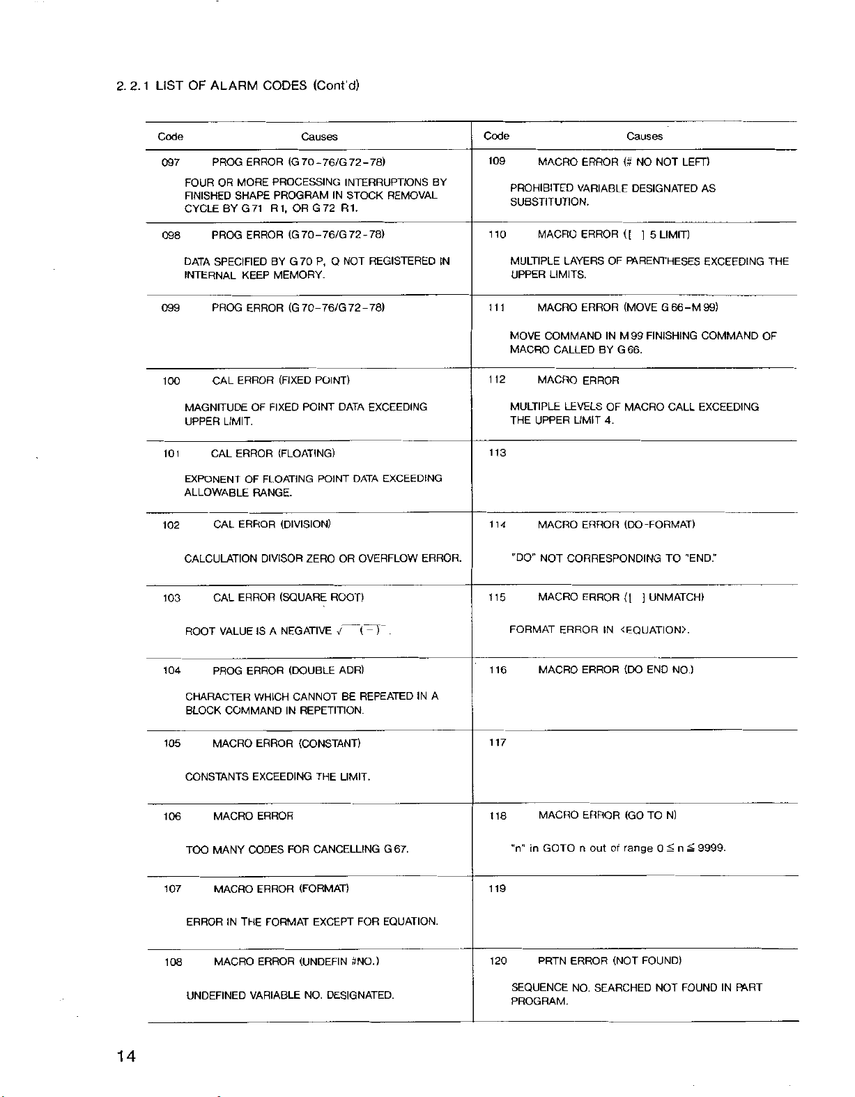
LIST
1
2.
2.
OF
ALARM
CODES
(Cont'd)
Code
097
FOUR
FINISHED
CYCLE
098
DATA
INTERNAL
099
100
MAGNITUDE
UPPER
101
EXPONENT
ALLOWABLE
102
PROG
ERROR
MORE
OR
SHAPE
G
71
BY
ERROR
PROG
SPECIFIED
KEEP
ERROR
PROG
ERROR
CAL
OF
LIMIT.
CAL
ERROR
OF
RANGE.
ERROR
CAL
Causes
(G
-
70
PROCESSING
PROGRAM
1,
R
G
OR
(G
-76/G
70
G70
P,
BY
MEMORY.
(G
-76/G
70
POINT)
(FIXED
POINT
FIXED
(FLOATING)
FLOATING
POINT
(DIVISION)
78)
72
76/G
-
INTERRUPTIONS
STOCK
IN
72R1.
72-78)
Q
REGISTERED
NOT
72-78)
DATA
EXCEEDING
DATA
EXCEEDING
REMOVAL
BY
IN
Code
109
MACRO
PROHIBITED
SUBSTITUTION.
110
MACRO
MULTIPLE
UPPER
111
MACRO
MOVE
MACRO
112
MACRO
MULTIPLE
THE
UPPER
113
114
MACRO
ERROR
VARIABLE
ERROR
LAYERS
LIMITS.
ERROR
COMMAND
CALLED
ERROR
LEVELS
LIMIT
ERROR
Causes
(#
NO
DESIGNATED
([
]
OF
FARENTHESES
(MOVE
IN
M99
G
66.
BY
OF
MACRO
4.
(DO
LEFT)
NOT
LIMIT)
5
G
66-M
FINISHING
CALL
-FORMAT)
AS
EXCEEDING
99)
COMMAND
EXCEEDING
THE
OF
CALCULATION
103
104
105
106
107
108
CAL
ROOT
PROG
CHARACTER
BLOCK
MACRO
CONSTANTS
MACRO
TOO
MANY
MACRO
ERROR
MACRO
DIVISOR
ERROR
IS
VALUE
ERROR
WHICH
COMMAND
ERROR
EXCEEDING
ERROR
CODES
ERROR
IN
THE
FORMAT
ERROR
ZERO
(SQUARE
A
NEGATIVE
(DOUBLE
CANNOT
IN
REPETITION.
(CONSTANT)
FOR
(FORMAT)
(UNDEFIN
OVERFLOW
OR
ROOT)
-
)
(
V
ADR)
REPEATED
BE
LIMIT.
THE
CANCELLING
EXCEPT
FOR
#NO.)
ERROR.
.
IN
G
67.
EQUATION.
TO
UNMATCH)
j
NO.)
END
''END;
115
116
"DO”
NOT
MACRO
FORMAT
MACRO
CORRESPONDING
ERROR
ERROR
ERROR
(l
<EQUATION>.
IN
(DO
A
117
118
119
120
'TV'
MACRO
GOTO
in
PRTN
ERROR
out
n
ERROR
of
(NOT
(GO
range
N)
TO
0
FOUND)
9999.
n
14
UNDEFINED
VARIABLE
DESIGNATED.
NO.
SEQUENCE
PROGRAM.
NO.
SEARCHED
NOT
FOUND
IN
FART
Page 19
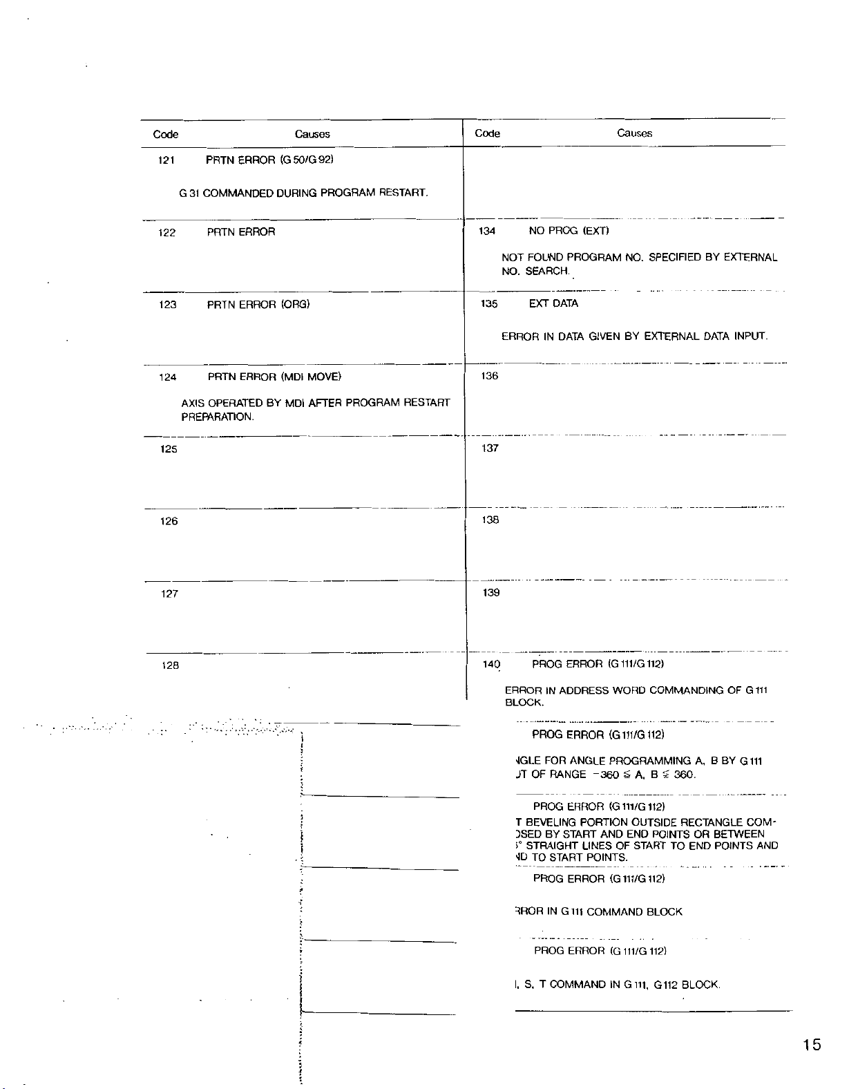
Code
Causes
Code
Causes
121
COMMANDED
G
31
122
123
124
AXIS
PREPARATION.
125
126
ERROR
PRTN
ERROR
PRTN
PRTN
ERROR
ERROR
PRTN
OPERATED
(G50/G92)
DURING
(ORG)
(MDI
MDI
BY
PROGRAM
MOVE)
PROGRAM
AFTER
RESTART.
RESTART
134
135
136
137
138
NO
FOUND
NOT
NO.
SEARCH.
EXT
ERROR
PROG
DATA
IN
DATA
(EXT)
PROGRAM
GIVEN
NO.
SPECIFIED
EXTERNAL
BY
BY
EXTERNAL
DATA
INPUT.
127
128
139
ERROR
140
PROG
ERRORINADDRESS
BLOCK.
PROG
ERROR
1
'iGLE
FOR
JT
OF
RANGE
(G111/G112)
(G111/G112)
ANGLE
-360
COMMANDINGOFG
WORD
PROGRAMMING
$
A,
B
360.
111
A,
B
BY
111
G
?
PROG
ERROR
!
i
;
i'
:
!
L
r
T
BEVELING
BY
DSED
STRAIGHT
>°
vJD
TO
START
PROG
IN
3ROR
PROG
START
ERROR
Gill
ERROR
(G111/G112)
PORTION
END
AND
LINES
OF
POINTS.
(G111/G112)
COMMAND
(G111/G112)
OUTSIDE
POINTS
START
TO
BLOCK
RECTANGLE
BETWEEN
OR
POINTS
END
COM-
AND
5
I,
S,
T
COMMAND
IN
111,
G
G
112
BLOCK.
t
15
J
Page 20
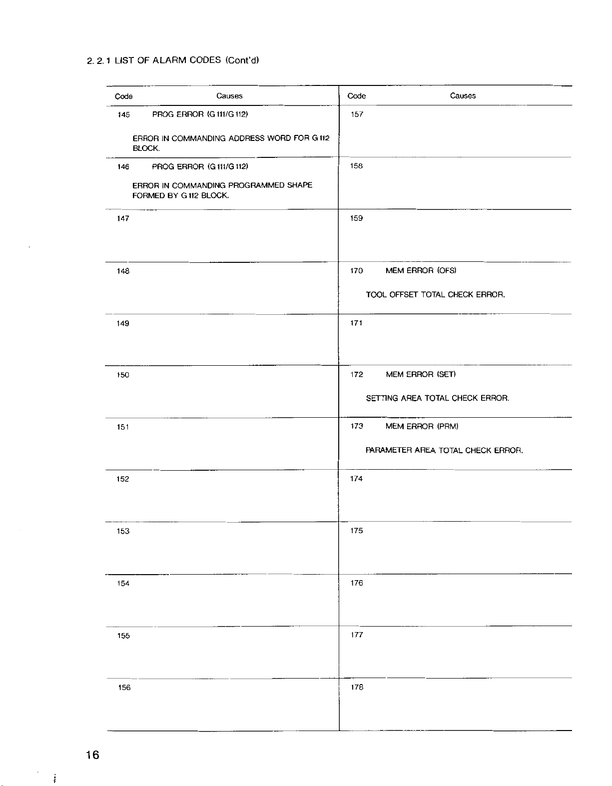
2.2.1
LIST
OF
ALARM
CODES
(Cont'd)
Code
PROG
145
ERROR
ERRORINCOMMANDING
BLOCK.
PROG
146
ERROR
FORMED
147
ERROR
IN
COMMANDING
G
BY
148
149
150
112
Causes
(G111/G112)
(G111/G112)
BLOCK.
ADDRESS
WORD
PROGRAMMED
FOR
SHAPE
Code
157
112
G
Causes
158
159
170
171
172
TOOL
MEM
ERROR
OFFSET
ERROR
MEM
(OFS)
TOTAL
(SET)
CHECK
ERROR.
151
152
153
154
155
156
SETTING
173
PARAMETER
174
175
176
177
178
MEM
AREA
ERROR
AREA
TOTAL
(PRM)
TOTAL
CHECK
CHECK
ERROR.
ERROR.
16
;
f
Page 21
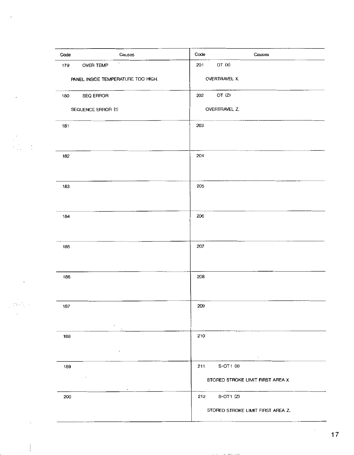
Code
179
OVER
TEMP
Causes
Code
201
OT
Causes
(X)
180
181
182
183
184
185
INSIDE
FANEL
SEQ
SEQUENCE
TEMPERATURE
ERROR
ERROR
(1)
TOO
HIGH.
OVERTRAVEL
202
OVERTRAVEL
203
204
205
206
207
OT
X.
(Z)
Z.
186
187
188
189
200
208
209
210
211
212
S-OT1
STORED
S-OT1
STORED
(X)
STROKE
(Z)
STROKE
LIMIT
LIMIT
FIRST
FIRST
AREA
AREA
X.
Z.
17
Page 22
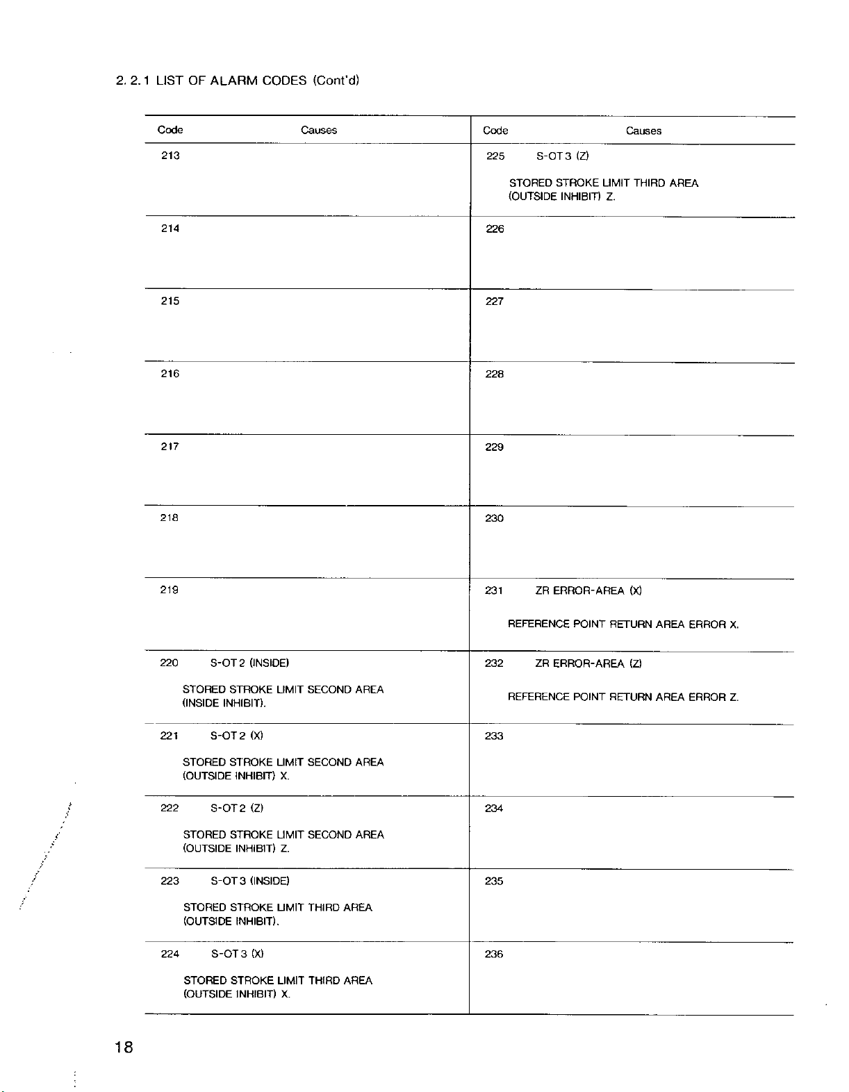
2. 2.
1
LIST
OF
ALARM
CODES
(Cont’d)
Code
213
214
215
216
217
218
Causes
Code
225
226
227
228
229
230
S-0T3
STORED
(OUTSIDE
(Z)
STROKE
INHIBIT)
LIMIT
Z.
Causes
THIRD
AREA
219
(INSIDE)
220
221
i
222
/
f
223
224
S-OT2
STORED
(INSIDE
S-OT2
STORED
(OUTSIDE
S-OT2
STORED
(OUTSIDE
S-OT3
STORED
(OUTSIDE
S-OT3
STORED
(OUTSIDE
STROKE
INHIBIT).
(X)
STROKE
INHIBIT)
(Z)
STROKE
INHIBIT)
(INSIDE)
STROKE
INHIBIT).
(X)
STROKE
INHIBIT)
LIMIT
LIMIT
X.
LIMIT
Z.
LIMIT
LIMIT
X.
SECOND
SECOND
SECOND
THIRD
THIRD
AREA
AREA
AREA
AREA
AREA
231
REFERENCE
232
REFERENCE
233
234
235
236
ZR
ERROR-AREA
POINT
ZR
ERROR-AREA
POINT
(X)
RETURN
(Z)
RETURN
AREA
AREA
ERROR
ERROR
X.
Z.
18
Page 23
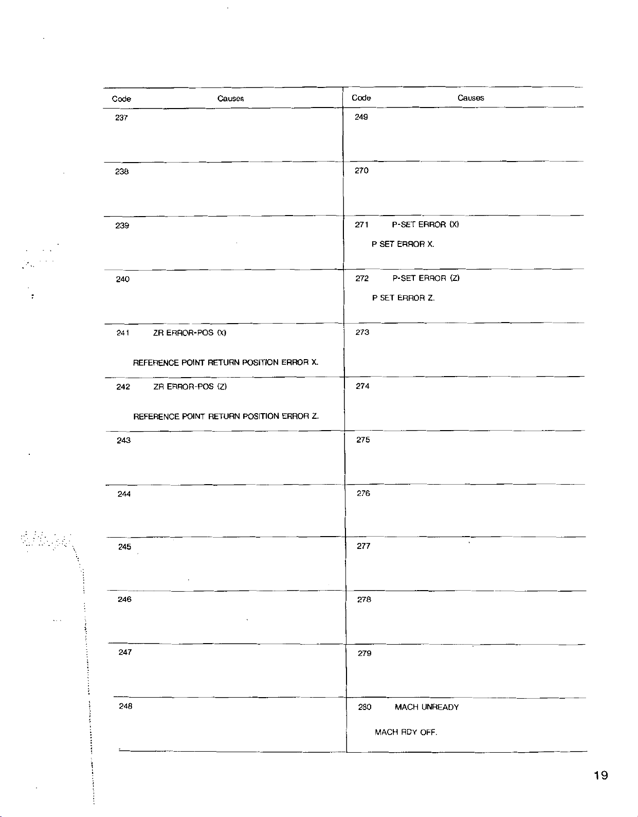
Code
Causes
Code
Causes
237
238
239
240
241
REFERENCE
242
ZR
ERROR-POS
POINT
ZR
ERROR-POS
(X)
RETURN
(Z)
POSITION
ERROR
X.
249
270
271
272
273
274
P
P
SET
SET
P-SET
ERROR
P-SET
ERROR
ERROR
X.
ERROR
Z.
(X)
(Z)
Z.
RETURN
REFERENCE
243
244
245
:
246
247
!
248
!
>
POINT
POSITION
ERROR
275
276
277
278
279
280
MACH
MACH
RDY
UNREADY
OFF.
:
i
:
19
i
'
Page 24
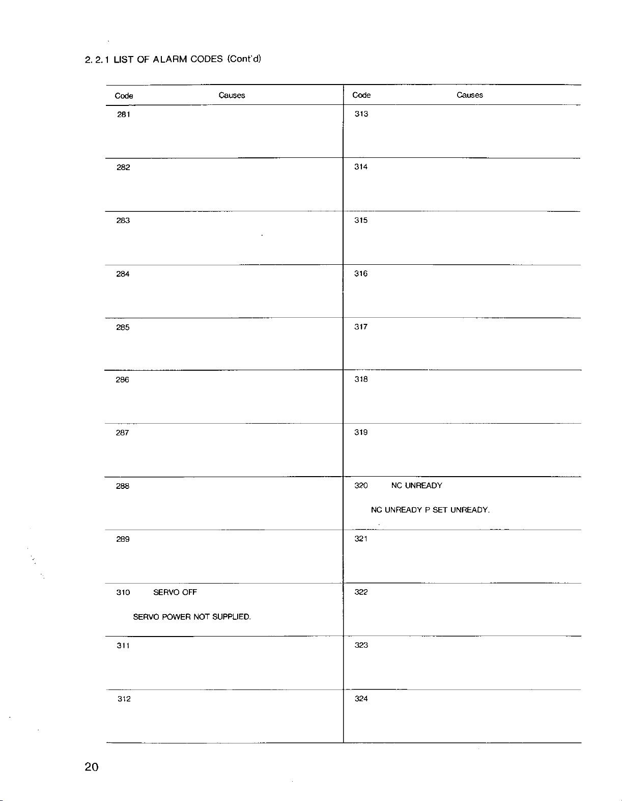
2. 2.
1
LIST
OF
ALARM
CODES
(Cont'd)
Code
281
282
283
284
285
286
Causes
Code
313
314
315
316
317
318
Causes
287
288
289
310
311
312
SERVO
SERVO
POWER
OFF
NOT
SUPPUED.
319
320
321
322
323
324
UNREADY
NC
UNREADY
NC
SET
P
UNREADY.
20
Page 25
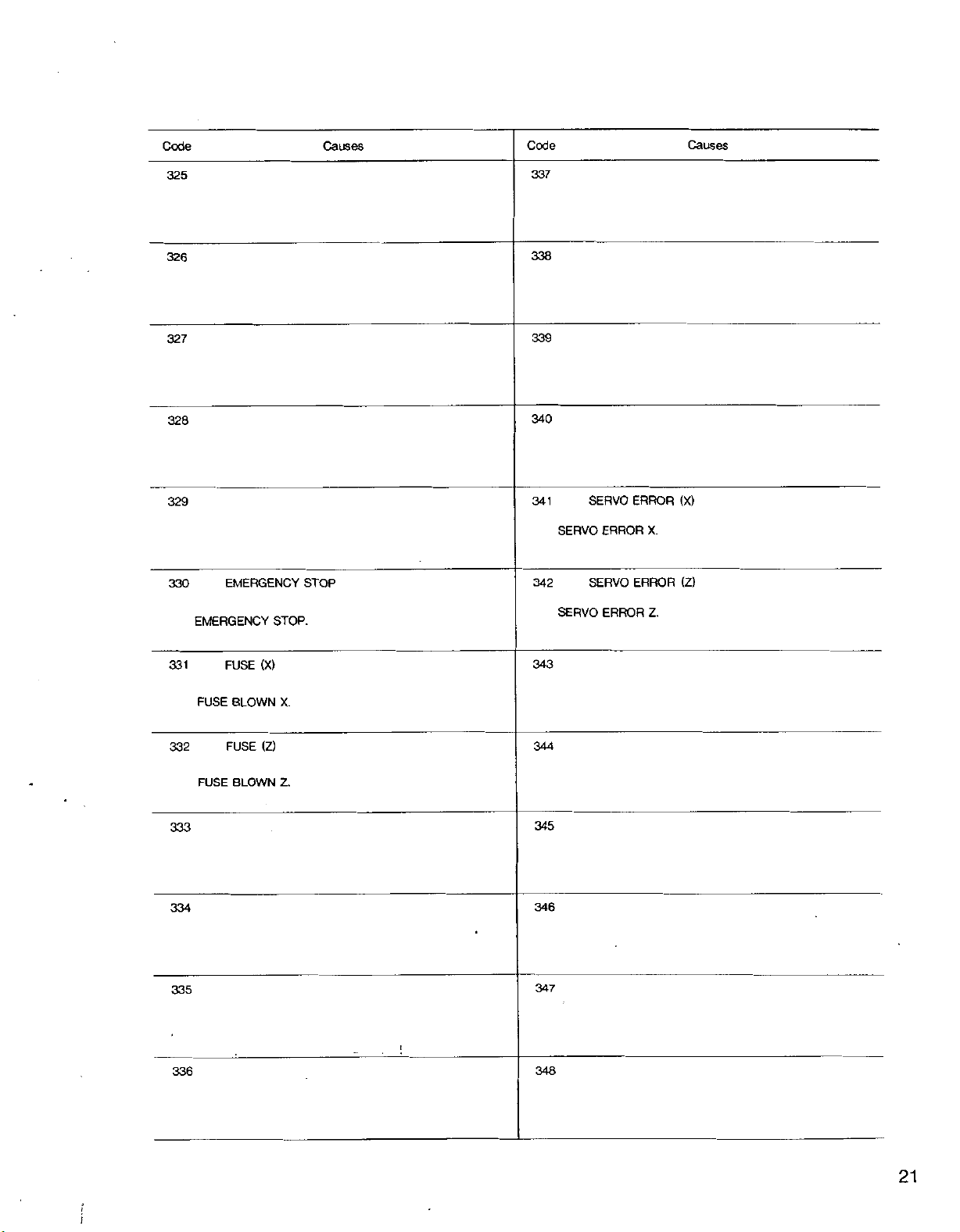
Code
Causes
Code
Causes
325
326
327
328
329
330
EMERGENCY
EMERGENCY
STOP.
STOP
337
338
339
340
341
342
SERVO
SERVO
SERVO
SERVO
ERROR
ERROR
ERROR
ERROR
(X)
X.
(2)
Z.
331
332
333
334
335
336
FUSE
FUSE
FUSE
BLOWN
FUSE
BLOWN
(X)
(Z)
343
X.
344
Z.
345
346
347
i
348
21
:
Page 26
LIST
OF
1
2.
2.
ALARM
CODES
(Cont'd)
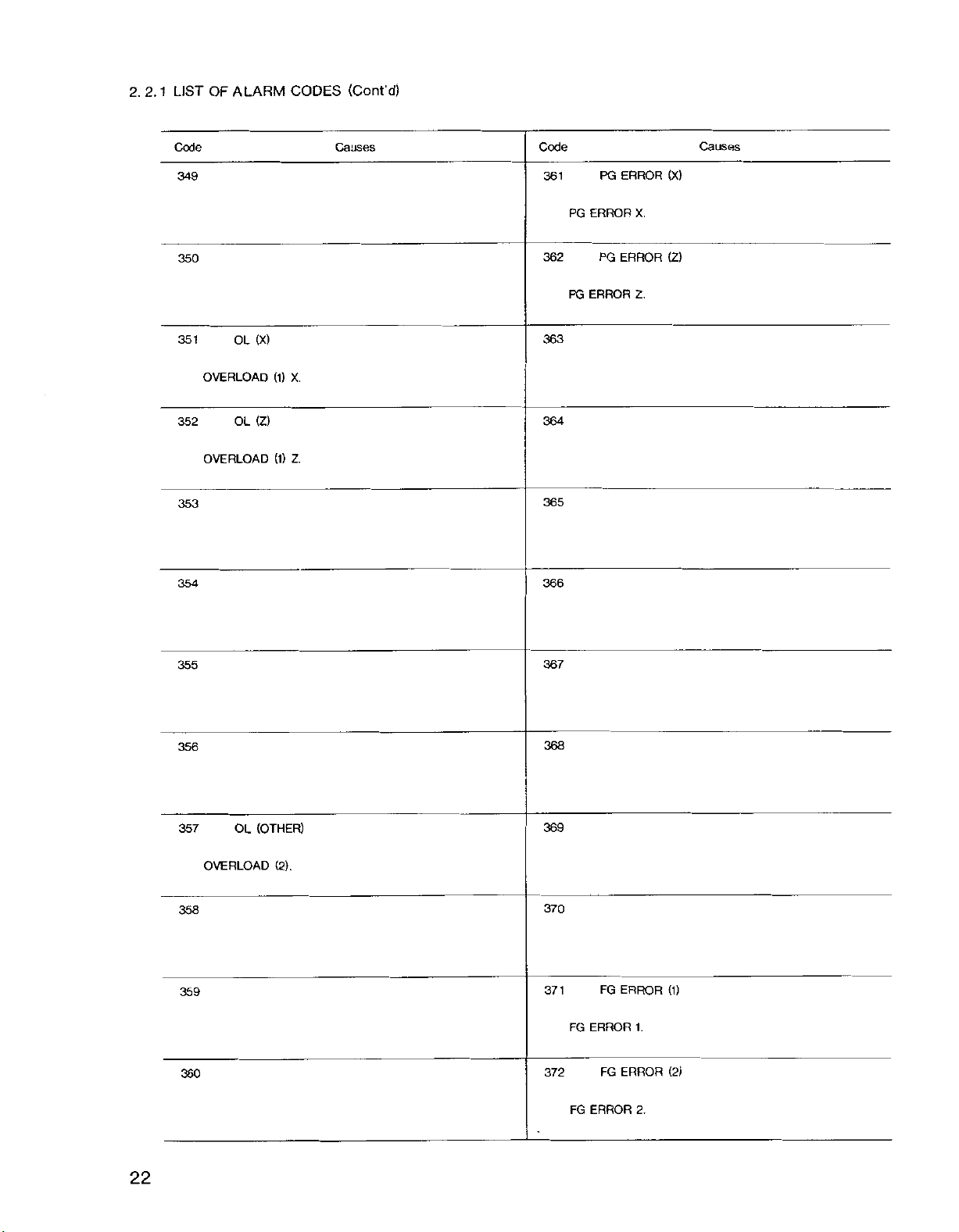
Code
349
350
351
OVERLOAD
352
OVERLOAD
353
354
OL
OL
(X)
(2)
(1)
(1)
X.
2.
Causes
Code
361
362
363
364
365
366
PG
PG
PG
ERROR
PG
ERROR
ERROR
X.
ERROR
2.
Causes
(X)
(2)
355
356
357
OVERLOAD
358
359
360
OL
(OTHER)
(2).
367
368
369
370
371
372
FG
FG
FG
ERROR
FG
ERROR
ERROR
1.
ERROR
2.
(1)
(2)
22
Page 27

Code
Causes
Code
Causes
373
374
375
376
377
378
385
386
387
388
389
390
379
380
381
382
383
384
PRG
ERROR
PRG
ERROR.
391
392
393
394
395
396
TG
TG
TG
LEAD
TG
LEAD
ERROR
ERROR
(X)
DISCONNECTION.
(Z)
DISCONNECTION.
*
.
\
1
;
23
\
Page 28

V
*»-*
'
2.
2.
1
LIST
OF
ALARM
CODES
(Cont’d)
Code
397
398
399
400
401
402
SEQ
SEQUENCE
ERROR
ERROR
(2).
Causes
Code
409
810
811
812
813
814
Causes
403
404
405
406
407
408
815
816
817
818
819
820
ROM
ROM
CHECK
ERROR
ERROR.
24
Page 29

Code
Causes
Code
Causes
821
822
823
824
825
826
833
834
835
836
837
838
827
828
829
830
831
832
CPU
ERROR
CPU
ERROR
(1).
839
840
841
842
843
844
CPU
CPU
ERROR
ERROR
(2).
25
Page 30

2. 2.
1
Code
845
LIST
OF
ALARM
CODES
Causes
(Cont’d)
CUTTING
START
POINT
846
847
848
849
910
920
TAPE-MEM
MEMORY
TAPE
TAPE
READING-IN
ERROR
VERIFYING
ERROR
ERROR
ERROR
(OFF-LINE).
(OFF-LINE).
Z-coordinate
•••
G72
point.
ALARM
•
Commanding
X(U),
•
Commanding
X(U),
In
addition
ed
among
straight
•
Address
dress
command
R1
"140"
Z(W)
Z(W)
addresses
line.
C
P
specifying
for
finished
or
one
specifying
two
addresses
specifying
this,
to
specifying
shape
exceeding
CUTTING
START
POINT
I
address
no
second
second
or
one
I,
A,
first
first
rounding
program
cutting
of
no
,
K
specifying
beveling
of
addresses
straight
addresses
straight
address
commanded.
by
start
line.
B,
line.
command¬
first
and
ad¬
,
B
ALARM
11
X-coordinates
start
ting
program.
Z-coordinates
cutting
shape
start
program.
Z-coordinate
different
mand
of
block
...
G71
R1
X-coordinate
different
mand
block
G72
of
R1
...
X-coordinate
G71
...
point.
095”
point
the
the
RI.
diffemt
and
different
point
for
from
finished
is
excepted.)
for
from
finished
is
excepted.)
for
Command
last
and
cutting
Z-coordinate
cutting
X-coordinate
finished
between
block
between
last
start
shape
start
shape
exceeding
block
program.
program.
shape
G71
for
G72
point
point
command
finished
command
finished
for
by
for
by
for
program
cutting
shape
G71
first
the
(Command
G?2
first
the
(Command
by
cut¬
com¬
com¬
start
•
Address
Q
dress
Commanding
ond
straight
beveling
ALARM
11
Command
first
straight
programmed
Command
-360.000,
0,
180.000,
-270.000,
90.000,
D
specifying
specifying
and
143"
values
line
shape
Value
-180.000,
360.000
-90.000,
270.000
addresses
and
line
rounding
for
are
cannot
A
for
second
second
X
Q
.
addresses
determined
Address
ifying
first
Address
ifying
first
rounding
and
and
be
formed.
I
commanded
straight
commanded
K
straight
beveling
Z
specifying
D
specifying
I,
A,
as
line.
line.
and
commanded.
K
specifying
follows,
spec¬
for
spec¬
for
ad¬
sec¬
second
and
26
Page 31

Command
specifying
follows,
as
formed.
Command
-360.000,
0,
180.000,
-270
90.000,
values
value
000.
270.000
second
and
-180.000
360.000
-90.000
for
addresses
straight
programmed
for
B
Address
fying
Address
fying
X
second
Z
second
line
shape
(U)
straight
(W)
straight
X(U),
B,
determined
are
cannot
commanded
line.
commanded
line.
for
for
Z(W)
be
speci¬
speci¬
ALARM
•
X(U)
•
X(U)
•
R
not
and
1
"O'1
•
P
and
•
Q
andDboth
ALARM
"145"
Z(W)
or
Z(W)
and
commanded.
not
K
commanded
C
both
"146"
commanded.
not
both
Or
commanded.
fori
commanded.
commanded.
commanded.
"0"
commanded
K.
and
for
R.
Command
too
ing
cannot
tion
Command
radius
med
shape.
the
to
No
intersecting
second
values
large
be
values
for
rounding
command
straight
for
the
for
made
END
POINT
for
Operation
.
1
point
line.
addresses
programmed
according
*
—
address
too
large
cannot
\
1*
for
first
\
\
i
V
C
to
START
POINT
and
P
for
be
\
\
START
h
POINT
V
straight
and
shape.
the
Q
the
made
bevel¬
D
for
Opera¬
command.
specifying
program¬
according
line
and
Beveling
Beveling
intersecting
No
straight
for
command
for
command
W
CENTER
CIRCULAR
ARC
line.
OF
K.
START
POINT
point
CENTER
CIRCULAR
ARC
H,
\
C
K.
D
I
between
OF
cannot
C/
/
cannot
K
K
K
START
POINT
circular
be
START
POINT
be
I
/
K/
made.
i
made.
START
POINT,
K
I
arc
and
END
and
POINT
START
POINT
second
straight
line
on
No
intersecing
end
point.
point
between
>
K
{
1’
l
K
!
First
the
straight
same
line
line.
l
START
POINT
circular
K
arc
and
l
‘2
’
K
I
\
\
;
i
i
\
27
Page 32

2. 2.
COUNTERACTING
2
ALARM
CODES
(1)
Alarm
The
checked
when
Even:
Odd:
(The
code.
010
number
on
number
the
for
for
description
)
EIA
ISO
(Tape
of
data
the
tape
tape
8
O
7
O
6
O
5
O
4
O
3
2
o
1
o
LSK
(IGNORED)
NC
is:
that
O
Horizontal
holes
for
tape.
follows
alarm
o
Error)
character
is
to
o
o
ooo
Parity
each
An
applies
o
o
o
OOO
O
o
o
o
o
EC01CN1GOX123'
R
R
L-
EOB
EOR
OOO
R
L
;
END
REWIND
:
O
1-
128
OR
is
issued
the
EIA
o
o o
OO
O
OO
o
BLOCK
DATA
CHARACTERS
LESS
BLOCK
OF
STOP
OO
456C
CODE
CODE
O
o
O
o
o
R
o
OO
o
M3
o
o
o
o
o
o
o
OCE
R
R
J
Fig.
2.2
(
ALM
The
operating
v
Tape
Tape
head
lit.
010
control
from
punched
tape
?
/
YES
faulty.
NO
reader
contaminated
NO
)
NO
YES
operable.
is
MEM
of
Number
(for
Numberofholes
(for
Punched
sharp.
Tape
Clean
holes
ISO).
EIA).
holes
contaminated.
tape
reader.
not
odd
even
Battery
module
Check
and
Create
or
faulty,
tape
modify
another
memory
puncher
tape.
NC
tape.
28
Tape
CPU
reader
module
or
is
data
faulty.
8-CHANNEL
USE
(EIA
RS-277,
BLACKORGREY
1154,
ISO
JIS
Fig.
C6246)
2.
3
PAPER
TAPES.
Page 33

Tape
Reader
Connections
TAPE
INTERFACE
PTR
(
INTERFACE
<F
—
6
245
8
244
READER
)
+
3CY
+
OV
6
{3
11
x
OV
14
12
5V
25
3RY
€3
11
CY
P
RY
100
8
C
iTRO
C
33
TR1
C
9
L
C
32
C10
31
C
1.
C11
TR3
C
30
C12ÿTR4
C
29
it
TR5
13
C
M
C
28
it
TR6
14
C
Jp
C27
JU
it
C
15
;fTR7
C26ÿ
-
,STRB
C
19
.
it
22
0
A
it
C16LTR
25
C
__C1Zÿ
TR
V
RUN
REV
AC
PT
P
P
P
P
Pi
PT
P
p~T
P
(TAPE
(TAPE
2400-1
DATA
SIGNAL
REELS)
READER)
SIGNAL
SELECT
HND
33
32
10
31
30
12
29
24
11
13
28
14
27
15
26
19
22
16
25
17
8
i
9
i
vj
1
2
'
E
PTR
MODEL
•
a,
READ
.
SPROCKET
START
:
DIRECTION
:
SIGNAL
rB
rB
Or
I
I
I
5V
+
OV
V
24
+
OV
Fig.
C3ÿ
C4
i
C
38
C37ÿ
C1
it
C
2
-it-
C
40
1
C
39
Tape
2.
4
Reader
Pi
P
PT
PT
Connection
3
4
:
38
37
5
1
2
40
39
Diagram
CONTROL
SUPPLY
MOTOR
SUPPLY
(5
POWER
VDC)
POWER
(24
VDC)
i
29
Page 34

2.
(2)
075:
076:
077:
COUNTERACTING
2.
2
RS
no.
RS
RS
were
FACIT
punching
depressing
key.
Setting
data
correctly.
075,
232C
of
232C
232C
read-in
4070
with
keyed-in
written
bits
Alarm
No
effective
"0-9999”
and
OUT
YES
076,
interface;
and
interface;
interface;
ALARM
077
no.
after
NO
CODES
(RS
232C
disagreement
baud
of
transmission
characters
10
stop
code
if
4,
D
faulty)
6003
D
(Cont'd)
rates
was
5
=
between
failure
or
issued.
0
more
SELECTION
Select
bers
(a)
(b)
the
.
Selection
PTR
RS
RS422
Interface
*
only.
Selection
Output
FACIT
Interface
Current
Interface,
Interface
RS
interface
Input
to
Interface
232
to
422
INTERFACES
OF
input
of
Interface
be
used
C
Interface
Interface
for
of
output
Interface
be
used
4070
Loop
RS
232
Interface
*
tape
to
interface
reader
C
be used
ft
6003
IDVCE
0
0
1
unit
interface
#
6003
ODVCE1
0
0
1
D
1
1
(optional)
D
5
sitting
by
6003D0
#
IDVCE
0
1
0
6003
ft
ODVCEO
0
1
0
num¬
0
D
4
connections
Detailed
gation
RS
punching
No
effective
"0-9999"
depressing
and
key.
OUT
Setting
data
correctly.
Parameter
written
connections
correct.
Detailed
gation
Cable
proper.
investi¬
required.
is
232
with
written
YES
properly.
YES
i
Cable
investi¬
is
YES
C
keyed-in
YES
required.
NO
NO
NO
NO
Fig.
Fig.
Check
2.5
6003
it
D4
=
0
D
=
6028
it
6026
it
Baud
Stop
Control
setting.
Check
2.6
wiring.
1,
1,
rate
bit
wiring.
5=0
D
D
1
(OUT)
(IN)
setting.
setting.
code
Common
Indepen¬
dent
Baud
rate
value
Input/
Output
Input
Output
50
100
110
150
200
300
600
1200
2400
4800
OUT
IN
0
=
Setting
9600
of
stop
Common
Independent
Setting
of
control
Common
Independent
bit
Input/
Output
Input
Output
input/
Output
Input
Output
it
D
#
3
D
tt
03
length
code
6026
3
6026
6028
0
0
0
0
0
0
0
0
1
1
1
6026
it
6026
it
6028
it
output
6026
it
6026
it
6028
it
6026
it
D
tt
6026
2
D
tt
6028
2
D
0
0
0
0
1
1
1 1
1
0
0
0
D
D
D
D
D
D
2
4
4
4
5
=
=
5
5
6026#6026
ft
1
D
it
6026
1
D
tt
6028
D
1
0
0
1
1
0
0
1
0
0
i
:
Two
1
=
stop
:
One
0
=
stop
:
Does
1
control
:
Sends
0
code.
DO
#
6026
o
D
tt
0
D
bits
bit
bit
bit
not
code.
control
6028
0
1
0
1
0
1
0
1
0
1
0
for
for
send
30
Page 35

Signals
Timing
P.
I
DATE
READY
PUNCH
and
100ÿ8
100
1
J
100
fis
Symbol
PR
TL
1
ERR
6V
+
0V
0V
OV
CH
1
CH
2
CH
3
CH
4
CH
5
CH
6
CH
7
CH
8
CH
9
PI
numbers
Pin
equipment
is
DB-25
Connection
AS
MS
10
FACIT
(MR-
NC
Signal
PUNCH
READY
TAPE
LOW
ERROR
Not
FACIT/
ASR.
Auto-
selection
Not
Not
GROUND
GROUND
GROUND
PUNCH
DATA
PUNCH
DATA
PUNCH
DATA
PUNCH
DATA
PUNCH
DATA
PUNCH
DATA
PUNCH
DATA
PUNCH
DATA
FEED
HOLD
PUNCH
INSTRUC¬
TION
is
P.
MIN
MIN
4070
20
Name
Used
Used
Used
are
FACIT
MS
18
MS
18
10MS
Fig.
Interface
F)
1
2
3
4
5
6
7
8
applicable
1
4070
Pin
No.
10
Diagram
MAX
MAX
n
7
2.
Connections
1
o
2
o
3
o
4
5
o
6
7
8
9
o
1
1
o
12
o
13
14
15
16
17
18
19
20
and
10
MS
Timing
Connecting
—
—
—
—
—
o
—
—
—
o
—
—
o
o
—
o
—
o
—
—
o
o
—
—
o
when
plug-in
for
o
o
o
o
o
o
o
o
o
o
o
o
o
o
o
o
the
FACIT
10
Cable
External
Equipment
(DB-25
Pin,
No.
12
21
20
24
10
25
1
2
3
4
5
6
7
8
9
11
external
connector
MS
Symbol
PR
TL
ERR
+
SD
0V
CH
CH
CH
CH
CH
CH
CH
CH
CH
PI
4070
n
P)
6V
1
2
3
4
5
6
7
8
9
(20
NC
Not
FACIT/ASR.
Auto-selection
Current
2
Current
GROUND
:
type
the
pin
connector
to
RS
NC
Frame
Sending
Sending
Receiving
Capable
Not
Signal
Not
Loop
(MR-20
Signal
Used
Used
Not
of
equipment.
current
No.
the
232
(DB-25
Signal
used
used
Current
Symbol
L
6V
+
TTY
TTY
1
ov
Note
.
The
1
1
external
When
2.
circuit
plug
plug
Symbol
FG
SD
RD
RS
CS CS
SG
F)
Name
loop
loop
connector
loop
(signal
4
DB-25P
receptacle
NC
C
Interface
P)
Name
grounding
data
data
data
sending
of
grounding
mA)
(—
(4-)
Interface
Pin
No.
)
20
and
(20mA)
RS)
for
DB-25
Pin
No.
1
2
3
4
5
6
7
8
+
25
Connection
1
i
4
5
6
o
7
o
8
9
I
pin
number
interface
pin
and
RS
232
S.
Connecting
Connections
o
—
Ch
CO
o
Connection
—
o
—
o
are
different
used,
is
(signal
No.
5
C.
Then
Cable
o
rO
K3
rO
o
o
Cable
External
Equipment
Pin
No.
(Note
connect
(B)
External
Equipment
Pin
No.
Symbol
2)
with
short-
CS)
the
Symbol
FG
SD
RD
RS
DR
SG
(OR
ER
ALARM)
of
IO
31
l
Page 36

2. 2.
(3)
170:
172:
173:
These
data,
of
a.
b.
c.
COUNTERACTING
2
MEM
MEM
MEM
alarms
parameter
and
following
of
170,
error
error
error
warn
unit
modules
memory
Alarms
the
Battery
Memory
Failure
172,
(OFS);
(SET);
(PRM);
that
reasons.
failure
(2)
ALARM
173
have
(Battery
not
module
(MEM
tool
error
setting
error
parameter
check
tool
been
connected
CODES
Error)
offset
offset
changed
alarm
(1)
or
area
error
(Cont'd)
total
area
amount,
display)
correctly.
(2).
total
due
check
check
total
setting
to
any
(5)
Alarms
(Zero
As
zero
Return
shown
point
reference
can
be
performed
turned
point
DECLS
(DECELERATION
LIMIT
off
has
SWITCH)
been
231
below
return
zero
and
(X),
Area
an
point.
the
completed.
1
232
Error)
alarm
is
only
manual
(Z)
made
Note
\
results
that
after
return
1_L
I
between
power
to
when
DECLS
this
error-check
reference
REFERENCE
ZERO
reference
supply
POINT
and
is
zero
Alarm
170
172
173
-
(4)
Alarm
High)
This
alarm
temperature
possible
high,
the
or
external
both.
I
No.
-
causes;
the
|
JANCD-
TU
C16
t
MEMORY
MEMORY
MEMORY
179
activated
is
45°C
is
cooling
ventilation
|
|
02
A
131
M1
i
CRT
(Panel
either
Display
ERROR
ERROR
ERROR
Inside
or
higher.
the
inside
fan
fan
JANCD-
I
|CP
07
13
:.M
o
2
TH
t
t“7
+
Fig.
(OFS)
(SET)
(PRM)
when
ambient
is
101
A
4.7
V
24
2.8
100
RY
K
-
the
stopped.
RY
Location
Memory
Module
MM09-XX
11
J,
11
Temperature
the
panel
There
temperature
control
Check
O
1
TH
I
CY
52
ip
T
0V
on
K
are
panel
Tool
inside
two
or
for
is
REFERENCE
POINT
(6)
Alarms
(Reference
This
type
point
(G27
ence
return
or
point.
PHASE
PHASE
PHASE
This
switch
SIGNAL
RAPID
JOG
G28)
A
B
C
check
is
(X),
241
Return
Point
of
alarm
performed
different
is
PULSES
PG
(REFERENCE
made
is
to
set
Fig.
242
90"
Fig.
"0."
2.9
(Z)
Area
results
manually
POINT
2.10
NOTE
when
II
from
PULSE)
the
Errors)
when
the
system
the
or
automatically
previous
S-OT
21
reference
No.
refer¬
H-<
20
32
•
The
thermostat
•
When
circuit
illustrated.
customer
system
the
pins
(OEM)
(contacts
C8
NOTE
is
and
can
usually
not
C16
another
add
closed).
use,
TU02,
short-
as
in
at
Page 37

C
Alarm
24
lit.
3
(7)
Alarms
This
between
ue
is
ter
positioning
type
32
271
of
current
pulses
Reference
point
ally
forms
-
Servo
faulty.
(X),
error
or
according
return
made.
PG
wave¬
propor.
Fig.
See
2.
9.
CPU
272
position
below
manu-
YES
/
module
(Z)
results
value
to
is
PG
(PSET
when
(set
by
command.
NO
NO
faulty.
and
parameter)
Error)
a
difference
command
point
matically
-v.
G
27
Operation
Reference
return
after
power.
val¬
af¬
return
made
G
or
NO
with
proper.
YES
incomplete
turning
Fig.
auto¬
28ÿ>
point
on
2.
11
G
by
00
YES
NO
Display
COMMAND
POSITION
on
the
X
X
Check
address
Feedback
faulty.
CRT
100
Less
100.33
X-
values.
is:
than
or
or
and
unit
Z-axis
is
99.968
more
Alarm
Operations
by
handle
EP
at
than
Investigate.
POSITIONING
BLOCK
(ÿ)
27
OK.
count
stop
more
32.
NO
NO
YES
H
I
error
ing
pulses.
zero
available.
.
output
D/A
faulty
(FANCD-CP
OUTSIDE
32
PULSES
Servo
occur
-
8192
at
Servo
adjustment
NO
02)*
OF
YES
YES
Fig.
•
load
Make
another
adjustment.
2.12
Parameter
"32"
#6056
#6057
"32":
"32”:
#6058
Motor
exces¬
sive.
NO
zero
settings
:
X-axis
Y-axis
Z-axis
YES
Check
Refer
(12)
--
to
on
machine
1
3.
page
58.
tool.
*
Measure
(1
pulse
the
1.22mV).
=
D/A
voltage
on
an
initial
power
application
33
Page 38

2. 2.
2
(8)
Alarm
This
ready)
NC
the
signal
(9)
Alarm
This
a
stop
depressed
switch
(10)
Alarms
(Servo
These
sistor
service
(11)
Alarms
COUNTERACTING
(Machine
280
signal
Ready
normal.
is
330
is
when
or
turned
is
Fuse
errors
.
personnel.
results
being
Signal.
(Emergency
displayed
emergency
the
when
on.
(X),
331
Blown)
attributable
are
Immediately
(X),
341
the
alarm
alarm
(s)
ALARM
from
OFF
332
342
CODES
Unready)
the
after
Check
Stop)
the
and
stop
machine
(Z)
contact
(Z)
(Servo
MRD
transmission
see
to
system
stroke
to
(Cont'd)
(machine
if
comes
pushbutton
end
damaged
the
Error)
un¬
the
MRD
limit
tran¬
YASNAC
10
24V
01
33
K
4.7K
Example
u
V
3.5
R
41
T
C
41
|
(OIL
PRESSURE)
MS2
-o
a
of
03-9
1,03-14
1
4V
2
+
Fig.
13
2.
to
is
SEQUENCE
NC
READY
MRD
ALARM
ON
OFF
-
Connection
c
Alarm
-ÿ
load
reduced
\
34
Heavy-
machining
progress.
Alarm
displayed
rate.
Motor
free
defects.
feed-
YES
of
YES
Fig.
2.
14
Sequence
lit.
)
YES YES
in
at
NO
NO
Worn-out
•
Roughened
surface.
alarm
No
no-load
in
operation.
NO
Motor
alone
NO
brush.
commutator
OK.
YES
Machining
taxing.
too
Load
motor
Replace
repair
condition
heavy
too
is
capacity.
or
brush
commutator.
is
for
TURNED
RESET
Change
condition.
Consult
builder.
tool
machining
the
OFF
SWITCH.
machine
By
34
Servo
faulty.
output
CPU
D/A
sent.
NO
module
YES
is
Servopack
faulty.
is
£
6074
6075
F
An
alarm
portion
left-hand
:
X-axis
16
:
Z-axis
16
is
issued
(follow-up
figure
when
deviation)
exceeds
the
8192
shaded
in
the
pulses.
*-7
T
Typical
parameter
(servo
2.15
Fig.
error
setting
area)
Page 39

(12)
Alarms
(Overload
Electronic
These
chining
(1))
thermal
alarms
condition
351
indicate
(X),
or
relay
machine
352
trip
overload.
(Z)
tool
Check
load,
the
ma-
(13)
Alarm
This
resistance
motor
rating),
motor
.
alarm
operation
failures
(Overload
357
is
initiated
temperature.
frequency
of
servo
by
(2))
too
Main
drive
(100%
high
causes
or
unit
regenerative
are
more
of
and
servo¬
high
the
(14)
The
the
to
TGON
C
Alarms
possible
servo
signal
Alarm
36
361
cause
CPU
being
JUSP-DCP
(X),
is
module
turned
lit.
)
362
that
C21
(Z)
no
despite
on.
ZT
0V
(type
OUT
55
1
A
OF
07
CY
ZC7)
PHASE
APPROX.
I
V
8
24
107
4.7
ov
A
JANCD-CP
V
RY
K
106
czu
K
33
90‘
RY
error)
input
the
JANCD-
02
TU
C
7
%
15
C
is
Servopack
A
given
A
Fig.
+
8
MB
9
2.16
•
'
M
PG
PHASE
9
Waveforms
A
1
C
(PG
PG
given.
Wiring
correct.
Feedback
faulty.
PG
input
NO
YES
unit
B
PHASE
Fig.
YES
NO
is
Fig.
2.17
Servo
faulty.
Correct
CPU
wiring.
module
is
•
PG
PHASE
PHASE
Waveforms
A
B
(type
90'
OUT
1
A
B
2.18
ZD7)
PHASE
OF
i
I
1
i
i
I
i
I
1
i
t
JlL
l
>
L_
r
Fig.
2.19
35
Page 40

COUNTERACTING
2.
2
2.
ALARM
CODES
(Cont'd)
(15)
(TG
MR-K:
Alarms
error)
The
wired
when
reverse.
(
(Y)
unit
when
the
,
393
PG
or
motor
)
YES
NO
NO
NO
NO
(X),
is
reverse
39
Motor
high.
B
and
+
correct
TG
A
-
correctly
on
D/A
of
proper.
.YES
392
lit
on
B
lit.
too
NO
terms'-'-
properly
YES
—
YES
B
PG.
YES
NC
unit
servo
391
alarm
in
A
and
Alarm
speed
'-"Motor
and
A
-'ÿconnectedÿ-'
--ÿWirincjÿÿ.
of
on
.
pulse
—
wired
output
-----
----
Investigate
motor.
or
(Z)
and/or
disconnected,
are
•
•
TG
wired
Check
motor
Does
TG
is
the
the
rotation
If
motor
terminals.
unit
terminals.
rotation
the
If
motor
terminals
terminals
rotation
If
the
connecting
motor
respectively
11,
J
rotation
If
the
connecting
motor
10,
respectively.
J
the
rotation
If
connecting
rotation
the
If
connect
respectively.
first
a
On
On
second
a
verification
for
Fig.
the
motor
is
or
in
TG
speed
wiring
and
B
pins
power
2.20
voltage.
is
is
is
is
is
is
connecting
power
to
clockwise
A
counterclockwise
A,
counterclockwise
application,
rating
and
from
viewed
from
(H)
M
?
exceed
correct
A
and
and
A
clockwise
pins
the
?
andBshouldbeconnected
respectively.
viewed
B,
respectively.
shouldbeconnected
B
viewed
(G)
L
.
and
viewed
PG
pins
check
D/A
M
pins
A
use
output.
viewed
(H)
from
J
viewed
and
the
EP
(G)
pins
L
clockwise
A
counterclockwise
and
application,
check
to
B
the
16
B
drive
drive
to
to
drive
and
to
D/A
(error
from
TG
from
TG
from
PG
output.
end,
end,
pins
pins
end,
18,
J
pins
pulse)
to
drive
to
drive
drive
servo
end,
servo
unit
connect
J10
and
end,
11
J
and
connect
respectively.
end,
and
J
18
connect
motor
16,
J
(16)
This
prevents
(17)
(T)
RAM
RAM
RAM
No.
100
3
3
101
3102
3
103
3
104
105
3
3
106
36
Alarm
alarm
Alarm
No.
Memory
810
the
820
check
3
and
Module
Type
09
MM
is
displayed
operation.
Location
(CPU
error
n
Location
Module
Board
7
7
6
6
5
5
3
error)
Faulty
E
D
E
D
E
D
E
820
on
when
RAM
RAM
No.
3
107
3
108
109
3
3
110
3
500
3
501
3
111
a
No.
CPU
Memory
Module
Type
MM
09
CP
02
CP
02
malfunction
Location
Module
Board
3
D
E
2
D
2
E
1
D
1
27
C
27
A
on
CP04
©
©MM09
PROM
PROM
3
error
y
error
ft
T_
820
Normal
Abnormal
P-ROM
820
Normal
Abnormal
P-ROM
total
No.
total
No.
total
total
value
value
(80-85)
value
value
(00-40)
Page 41

2.
3
TROUBLESHOOTING
WITHOUT
ALARM
CODES
following
The
correcting
which
(1)
Power
basic
flow
troubles
operations
cannot
First
impossible.
.
composite
of
supply
power
charts
not
be
power
Neon
shown
are
applied.
application
lamp
unit
YES
of
LED
input
lit.
YES
are
the
abnormal.
power
lit.
unit
instructions
alarm
by
NO
NO
codes,
for
in
power
the
Input
applied
NC
unit.
YES
to
_
NO
Connect
system.
the
Composite
blown
fuse
Power
out.
input
input
power
out.
unit
power
supply
blown
to
;
(2)
CPU
error
When
without
CPU
indicating
malfunctioned
vated.
personnel.
turned
1.
No
composite
supply
2.
+
circuited.
(with
ERROR
and
Immediately
Power
seconds
output
load
5V
flashes
any
the
off
about
YES
from
unit.
short-
no
watchdog
contact
later.
power
alarm
error
3
No.)
on
No.,
NO
CRT
the
the
timer
YASNAC
CPU
has
screen
acti¬
service
Fig.
has
2.21
(3)
When
is
operator's
If
service
No
indication
the
normally
cause
the
personnel.
CRT
panel
Power
buttons
operable.
Package
CP
on
screen
supplied,
and
cannot
04
the
be
ON/OFF
are
Type
failure.
CRT
remains
check
the
found,
push¬
freely
not
JANCD-
screen
blank
the
connector
wiring
contact
after
power
to
connection.
YASNAC
the
37
Page 42

2.
3
TROUBLESHOOTING
CODES
(4)
(Cont’d)
HANDLE
Handle
operation
MODE
selection
magnification
s.
desired.
pulses
MODE
mode
faulty.
HANDLE
selected.
YES
Axis
and
*
YES
Handle
generated.
\
as
.YES
or
data
PG
Handle
module
is
Continued
faulty.
T
to
©
operation
'
*
*
CPU
WITHOUT
is
#
DGN
07
6
D
#1301
DGN
07
D6D
“
HP
1-
1
#
DGN
6
7
D
D
H
H
X
z
#
DGN
7
6
D
D
i.J
H1H
H
1
7
P6P5P
P
Fig.
2.22
faulty.
1300
5
D
5
1302
D5D
1282
D5D
1
ALARM
4
D
3
D
3
D
4
0
D3D2D
4
D
4
H
1
HI
P
4
D
3
3
2
H
D2D
2
D
H
1H1
P
2
*
These
Displayed
Note
1
=
D
HP
4
D
P
1
1
1
I
1
:
7.5
£o]
DO
DO
HP
2
0
D
1
H
PO
checks
Set
mm/min.)
right
at
correctly
'"\handle
Data
should
side
the
A
V
+12
/
across
ter¬
1
minals
—
handle
and
PG.
of
2
.YES
Pulses
3
,YES
Pulses
to
of
data
module.
,YES
module
made
each
from
5
and
PG.ÿ--'''
con¬
F
CPU
is
by
displaying
check
#
of
faulty.
6222
item
(maximum
generated
terminals
input
nector
CPU
be
of
parameter
is
NO
NO
NO
I/O
the
Check
Handle
Check
signals.
correct
manual
power
for
Check
connectors.
is
PG
wiring
signal
states.
handle
supply.
shorted
faulty.
and
feedrate
cables.
;
•
38
Handle
PG
PAH
PBH
Connection
90*
OF
PGH
OUT
PHASE
Diagram
jL.
4
5,
6
1
DATA
CPU
+
+
12
5V
MODULE
07)
PG
V
)
(JANCD-CP
PAH
(PHASE
!
f
.
P
i
PBH
(PHASE
Ti
i
P
!
t
+12
0V
7
.
T
V
8
-
SIGNAL)
OAH
SIGNAL)
OBH
V
A
B
1
SHORTED
-
12V
(
V
Fig.
2.
23
5
16
F
17
F
F
9
18
F
-fP
19
f
M
F
12
F4
*
1
F
5
F
F
2
F
6
F
3
20
IF
PI
M-
P16
2
P
P15
.
CONNECTORS
HANDLE
HANDLE
OG
PG
PG
:
P1-P16
:
P2-P15
HANDLE
INTERFACE
f
i
CONNECTED'
CONNECTED
Page 43

(5)
Manual
jog
mode
operation
faulty
Jog
mode
mode
faulty.
Jog
pushbutton
depressed.
Jog
selected.
Jog
feedrate
input.
operation
*
YES
YES
*
NO
1302
DGN
it
D
D
7
06
D
DGN
D7D
5
-Z
#1300
6
5
D
D4
+
D
-X
Z
D
4
*
it
1301
DGN
7
6
D
4
D
D
5
16
JV
1
3
D
D
D.2
+
D
3
D
JV8
0
X
1
2
D
DO
J
1
3
2
D
4
JV
D
JV2
DO
JV
1
Note:
in
Note:No
if
no
feedrate
is
the
feedrate
given.
operation
No
automatic
operation
exceeding
given
is
is
operation
is
the
made
mode.
executed
or
the
rating
setting
Detailed
required.
is
Parameter
correct.
NO
investigation
These
*
Displayed
checks
at
should
right
side
step
Jog
#
6233
#
6264
be
made
of
each
I
Fig.
Jog
2.
displaying
by
check
feedrate
1
feedrate
24
item
0
1
T
mm/min
step
31
signals.
I/O
correct
the
is
CT
signal
=
0.1
=
in/mi
states.
n)
i
i
39
Page 44

TROUBLESHOOTING
2.3
CODES
(Cont’d)
WITHOUT
ALARM
(6)
Manual
rapid
Rapid
operation
pushbutton
depressed.
mode
Override
input
mode
mode
Jog
YES
Rapid
selected.
YES
entered.
NO
faulty.
*
operation
+
*
faulty
DGN
D7
DGN
D7
DGN
D7
#
1302
D6
D6
D4
-Z
+z
#
1300
D5
D6
D4D3D2
1301
ft
D5
D6
ROV ROV
1
2
D3
D2
D1
-X
+x
D1
D4D3D2
DO
DO
RT
D1
DO
ROV
ROV
PRM
25%
0
1
2
1
0
0
50%
0
100%
1
1
1
setting
Detailed
required.
is
Parameter
correct.
NO
investigation
*
checks
These
Displayedatright
6280
#
6282
ft
6286
ft
6288
ft
6231
ft
should
sideofeach
X
Rapid
feedrate
Z
1
7.5
=
(0.75inch/min)
mm/min
X
Rapid
acceleration/deceleration
1
=
125/8
mm/sec2
Z
Rapid
override
Fig.
2.
25
by
check
displaying
itemisthe
made
be
I/O
rate
F0
signals.
correct
signal
status.
40
;
Page 45

(7)
Manual
(i)
reference
zero
return
operation
faulty
Overtravel
without
return
selected.
Deceleration
LS
1
setting
Detailed
required.
is
results
deceleration.
YES
Zero
mode
YES
in
order
to0to
YES
Parameter
correct.
YES
investigation
DGN
#1304
7
D
*
ZBN
DGN
of
*
1.
D7
#
#6311
#6316
#
6
D
#
1306
D6D
*
6310
6317
5
D
5
DCZ
X
Zj
XI
Z
04D3
1
J
2
D
D
D4D3D2D
*DCX
Approach
point
Approach
point
speed
return
speed
return
1
DO
1
DO
for
reference
1
1
75mm/min
=
2
for
reference
(0.75inch/min)
(ii)
Deceleration
overtravel.
in
reference
generated.
v
Feedback
faulty.
No
point
YES
Unit
results
pulse
is
NO
>
*
These
checks
Displayedatright
package
CP
02
shouldbemade
sideofeach
Fig
is
2.26
faulty.
Fig.
2.27
displaying
by
check
I/O
itemisthe
signals.
correct
signal
status.
41
Page 46

TROUBLESHOOTING
2.3
CODES
(Cont'd)
WITHOUT
ALARM
(8)
Cycle
c
start
Cycle
No.
Detailed
required.
is
failure
start
ST
signals
sp*
input.’
STLK
signal
absent.
System
switch
to
investigation
and
"0."
failure.
YES
*
YES
*
YES
set
)
#1304
DGN
D7
DGN
D7
DGN
D7
*
These
D5
06
3
1305
05
D6
ST
LK
1280
3
D5
D6
Displayed
D4
04
D4
checks
at
03
03
D3
1
should
right
Fig.
D2
D1
*
SP
01
02
01
02
sideofeach
2.
28
DO
ST
00
DO
0
be
made
SP*:
ST
“1”:
"1”:
by
displaying
check
:
T
"0“
NG
NG
item
"0"
to
'T
to
signals.
I/O
is
the
correct
signal
status.
(9)
No
operation
operation
No
with
G
input
Detailed
required.
available
available
01,
02
G
Distribution
progress.
in
YES
Override
given.
YES
Dry
pre¬
inpul
*
sent.
NO
investigation
G01,
DGN
07
DGN
D7
*
G02
3
D6
D6
These
Displayed
with
03.
or
G
*
is
Note
screen
1301
05
3
1303
05
or
:
checks
G03
The
during
D4
FV
16
04
DRN
character
D3
FV
8
03
right
at
distribution.
02
01
FV
FV
4
2
D
02
should
side
1
be
"F”
DO
FV
1
of
DO
made
each
blinks
at
Note
is
set
by
check
bottom
:
Check
0%,
at
displaying
item
CRT
the
of
override
the
if
see
to
or
200%
I/O
is
the
signals.
correct
or
higher.
signal
status.
42
Fig.
2.29
Page 47

(10)
Spindle
does
not
rotate.
•
Connection
Spindle
not
'
command
given
\
'
check
at
does
rotate.
Speed
voltage
spindle
to
drive.
NO
Voltage
terminal
B.
4
NO
Diagram
for
.
YES
YES
Spindle
SPEN
Check
Data
16
0
spindle
output
(sequencer).
CPU
B
4
1
E
drive
SPEN
present
module
7
I
unit.
0
defective.
DAS
NO
Fig.
Check
on
2.30
interlock
machine
tool
signal
side.
SPINDLE
D/A
’
OUTPUT
SG
DATA
CPU
(JANCD-CP01)
SPINDLE
BINARY
OUTPUT
SPEN
.
MODULE
12
BIT
1
o
OG
E
12
19
E
6
E
13
E
E201
£2ÿ
3
E
E
4
E6ÿ
8
E
E9
10
E
E
14
15
E
16
E
17
E
E18L.
H
$
i
I
I
j
X-
A-
j.
EN1
SGS
ENO
SGSO
R
1
2
R
3
R
R
4
5
R
R
6
7
R
R8
R
9
R10
11
R
12
R
1
SPINDLE
SPEED
LiCOMMAND
WITH
ON
>
T
SIGNAL
7
OR
f
ov
Fig.
2.
31
43
i
i
Page 48

2.3
TROUBLESHOOTING
The
(Cont'd)
9-inch
CODES
(11)
ment
*
I1
9
O
8o
JS-
VIDEO
Fig.
2.
32
BRIGHT
CRT
9”
CRT
screen
Screen
WITHOUT
brightness
Brightness
ALARM
adjust¬
CRT
9”
MAINFRAME
Adjustment
2.
4
ACGC
2.
4.
1
ACGC
The
following
(1)
Hardware
(2)
System
(3)
Application
For
service
When
gram,
machine
ble
2.
4.
2
MAINTENANCE
ACGC
ACGC
may
:
software
(1)
personnel.
the
contact
tool
ALARM
TROUBLE
fault
and
cause
the
SERVICE
as
fail
fault
program
(2),
seems
service
company.
INDICATION
the
fault
contact
to
ACTIVITY
result
be
agent
of
one
your
application
of
the
of
the
YASNAC
pro¬
applica¬
The
BRIGHT
user.
•
BRIGHT:
•
VIDEO:
not
Do
critical
screen
adjust
need.
control
adjusts
adjusts
brightness
to
contrast
the
The
faulty
The
The
stored
value
The
The
The
DC
When
bubble
can
satisfy
brightness
contrast
SYSTEM
PROM
PROM
12
+
power
PARAMETER
parameter
the
in
ACGC
the
BUBBLE
bubble
of
detail
possible
power
unit,
BUBBLE
the
bubble
memory
the
unless
Alarm
containing
appears
No.
V/—
12
supply
value
bubble
has.
memory
bubble
the
cause
or
loader
differs
be
desire
Indication
PROM
the
V
POWER
for
ERROR
indicating
memory
ERROR
does
may
graphic
.READ
from
adjusted
there
Table
TOTAL
system
| |
on
RS232C
differs
:
not
memory
be
a
module
ERROR
used,
Is
that
of
2.
2
and
ERROR
software
DOWN
interface
the
operate
error
fault
(CG
the
of
by
the
is
List
Cause
bubble
from
of
content
the
(1)
machine-triggered
of
the
(2)
the
content
a
panel."
Shooting
(3)
check,
an
ACGC.
ACGC
of
:
[
faulty.
is
.
faulty.
is
memory
parameter
the
correctly.
appears
the
02).
bubble
bubble
on|
of
loader.
YASNAC
the
machine
When
screen
ACGC
alarm.
Alarms
The
capacity
_
memory,
the
alarm,
as
For
by
and
system
refer
tool
company.
no
machine-triggered
indicates
for
the
details,
Alarm
performs
any
trouble
Table
Contact
YASNAC
Personnel.
Contact
YASNAC
personnel.
Initialize
memory
Contact
YASNAC
].
personnel
The
a
maintenance
which
YASNAC
personnel
tool
equipped
alarm
may
to
the
the
"9-inch
refer
Code.
self-diagnosis
in
describes
2.3
Action
bubble
the
correctly.
loader
bubble
operated
is
service
or
machine
manufacturer.
appear.
Instruction
alarm
CRT
to
ACGC
is
device
by
para.
with
alarm
code
NC
is
the
ACGC,
For
Manual
appears,
for
operator's
2.2
and
indicated
alarms
a
details
of
same
Trouble
data
by
of
44
Page 49

2.
4.
FAULTS
3
INDICATION
(1)
CRT
screen
If
nothing
is
AC
CRT
Supply
DC
+12
Wiring
After
turned
power
fuse
is
supply
If
power
(T)
(|)
(3)
terminal
(?)
V,
+5
(5)
again.
achieved,
nel.
(2)
(a)
screen
operation
(T)
connections.
(?)
for
(?)
keyboard
No
Although
after
Check
Check
V,
+5
Depress
is
NOT
appears
supply,
blown.
voltage
230
V,
and
between
checking
the
contact
message
power
accepted:
keyboard
the
V,
+12
a
key
DISPLAYED
remains
on,
check
VAC
±15%.
in
ACGC
-12
the
these
normal
your
operation
is
terminals
and
and
blank:
on
e.g.
at
V.)
PCB
YASNAC
may
turned
wiring
-12
check
the
the
one
the
normal.
is
items,
operation
is
of
V.
BY
CRT
following:
phase
ACGC
and
accepted
appear
on,
for
the
for
ACGC
screen
(Voltages
CRT
turn
service
loose
DC
beep.
a
ALARM
is
rear
is
on
cannot
(hang
the
on
no
keyboard
supply
after
open.
panel
correct.
power
person¬
CRT
or
open
are
up)
unit
be
The
brightness
best
ments
cal
light
is
trol
reduce
may
4.
2.
4
SOFTWARE
If
memory-related
memory,
recover
to
fication,
number,
methods
(1)
nameplate
:
Indicated
m
rvjl
3
*
©
/
©
©
@
+
condition
may
be
conditions.
maintained
fails,
the
software
and
the
on
[
]
0
at
made
the
life
VERSION
hardware,
is
it
stored
can
on
back
-
00000
00000
00000
00000
00000
0000
o
0000
©
®
-+•
CAUTION
been
has
factory
the
compensate
to
If
a
at
of
that
INDICATION
desirable,
often
software.
managed
is
determined
be
"System
of
the
00000
00000
00000
00000
00000
00000
OOOO
OOOOO
OOOO
OOOO
OOOO
O
o
0
OOOOO
OOOOO
n
£
the
high
O
O
preset
bright
circuit.
such
No.
CRT.
O
3
€
<L
-»
.
setting,
as
For
with
by
Label"
00000
00000
00000
00000
00000
00000
O
o
’
o
o
o
OOOOO
OOOOO
to
Adjust¬
for
con¬
the
after
easy
a
one
~F
OOOO
il-lslslil!
3>
the
lo¬
it
bubble
repair,
identi¬
version
of
on
two
the
-+
UJ
POWER
DC
SUPPLY
m
I
t
@
©
+
UNIT
[
[
FUSE
(125
]
/
4
V,
5
BRIGHT
CONTROL
OOOOO
/OOOOO
/OOOOO
1
00000
o
©
A)
Fig.
2.
OOOOO
OOOO
OOOO
OOOO
O
0000
OOOO
OOOO
33
O
Rear
0,0
OOOOO
OOOOO
OOOOO
00000
OOOOO
OOOOO
o
O
o
o
o
OOOOO
OOOOO
View
o
3
3-
of
o
<E
»-
'
ACGC
OOOOO
OOOOO
OOOOO
00000
OOOOO
OOOOO
0
O
O
o
OOOOO
OOOOO
F
OOOO
3
>TJ
VAC,
Unit
SUPPLY
±15%)
POWER
TERMINAL
(100
System
ACGC
Sign.
Date
‘9
y
'
Fig
Application
No.
2.
Date
34
PR
Sign.
Nameplate
Application
:
Date
On
Sign.
Back
BU
:
-
-
CRT
of
SYSTEM
NO.
LABEL
45
i
1
Page 50

4.
2.
SOFTWARE
4
VERSION
INDICATION
(Cont'd)
2.
5
SUPPLY
VOLTAGE
CHECK
screen
CRT
the
This
on
indication
appears
only
in
when
NC
power
(2)
(a)
below.
on
.
Displayed
sample
A
r
YASNAClLMm
SUBSYSTEM
SUBSYSTEM
NC
PC
MAIN
ACGC
(b)
below
Fig.
A
.
2.
35
sample
Sample
indication
APPLICATION
APPLICATION
Various,
of
in
NC
Mode
in
PROM
BUBBLE
Software
ACGC
mode
VERSION
Version
mode
is
is
05671.12
OOOQO.QO
03
0123
0245.35
78
0123
is
shown
turned
NO
Nos.
shown
2.
1
5.
RJ
©
®
©
13
Ln
CHECK
CN
14
C
CN
n
POWER
3
0
1
LED
CC
CN
15
17
CN
SUPPLY
CN
16
l
JANCD-TU
a:
CO
©
SN
©
02
CM
4
RL
VOLTAGE
CN
18
o
CA
CO
O
x
©
SVM
m
©
©
Fu
1
Fu
2
0
©
©
AJ
the
or
latest
ACGC
Fig.
When
your
[BUB
2.
36
service
version
MODE
|
Sample
memory-related
YASNAC
of
agent
number
)
ACGC
in
of
service
VERSION
|INTER|
Main
ACGC
machine
the
of
NO.
NC
f
Software
Mode
hardware
tool
office
related
26—
JULY-85
Version
fails,
manufacturer
and
software.
|PROM]
notify
report
Nos.
the
0
AMXBMX
©
©
0
©
©
EMX
© ©
Fig.
©
AMZ
2.37
0
EMZ
BMZ
© ©
I/O
©
© ©
0
Power
©
r
R
s
© ©
© ©
200/220/230
10%
+
50/60
Terminal
©
©
to
Hz
©
©
s
-15%
T
VAC,
G
©
46
Page 51

5.
2.
2
DC
POWER
SUPPLY
VOLTAGE
CHECK
J
l
will
lamp
be
Power
Rated
Output
+
24
+
12V
+
-12V
fuses
VAC
5V
NEON
It
encased
Input
200/220
Specifications
CN
1
S?
0
0
T
M?
«24
-12
12
7
OUTPUT
CONNECTOR
Fig.
2.
38
is
lit
distinguished
is
Supply
±15%,
of
Rated
Current
A
22
V
3
A
2.5
A
A
0.5
'o'
o
o
r
5
*5
*
EE
7
Composite
when
blown
Voltage
50/60
Composite
Table
Applicable
Voltage
5.0
5.25
22.08
26.4V
11.4
12.6V
-
1
2.0
-13.8
CN
2
pxg
nin
the
out.
o
if
Hz
2.
Range
-
V
-
-
-
V
i
[Q|X|iO
h?-j+i?t»>i
OUTPUT
TERMINAL
Power
NC
any
(r
Power
3
CN
3
7
Supply
unit
of
and
±2
Logic
Read
CRT,
I/O
CRT,
Position
circuitry
Position
circuitry
Q
foO+
+
is
two
the
of
s
Hz
Supply
Application
circuitry,
relay
tape
signals
memory,
control
control
oO-
-
24
Unit
powered.
glass-
5CN)
Unit
reader,
1TB
Q1
oO+
'+12''
12
LED
(GREEN),
7+5
SEQUENCE
5V
+
OUTPUT
VOLTAGE
ADJUSTING
POTENTIOMETERS
CIRCUIT
CONNECTOR
2.6
TICS
When
failure,
of
the
on
I/O
2.
6.
Note:
#1000
sequence
manual.
CN
4
Mo
W,OM
/vADJ
7
STATUS
FUNCTION
the
I/O
diagnostic
NC
control
signals
1
for
OUTLINE
Diagnostic
1000—
if
1100—
it
1200-
it
1300—it1350
ti
With
a
#1157
to
program.
5
CN
$
1
DO
FG
CPS-
20
10
A
10
7
FUSE
INPUT
POWER
CONNECTOR
NEON
(ORANGE)
DISPLAYBYON-LINE
(DCN)
NC
to
Display
signals
signals
signals
signals
setup
machine
unit
can
display
Contents
(PC)
(PC)
on
section
status.
OF
it
it
it
power
in
of
panel
DISPLAYS
Table
No.
sequence
meaning
Read
Input
tool
Output
tool
Output
sequence
Input
sequence
1096
1157
1291
the
numbers
2.4
(PC)
depending
the
N
POWER
A
LAMP
DIAGNOS¬
is
be
for
machine
to
machine
power
to
power
from
built-in,
each
builder's
tool
T
suspected
keyed-in
check
and
signals
power
i
47
Page 52

6.
2.
2
OUTPUT
Depress
1.
A
specified
screen,
displayed
Key-in
2.
ed,
This
containing
"I":
"0":
The
decimal
the
OPERATING
SIGNALS
the
page
containing
previously
with
in
the
will
diagnostic
depress
change
and
keyed-in
contact
contact
on
data
digits
screen.
PROCEDURE
(DGN)
"1,"
the
key.
"0"
the
the
the
will
status
and
number
CURSOR
number.
closed
open
each
line
rightmost
the
in
DISPLAY
TO
diagnostic
appear
hexadecimal
screen
is
displayed
of
on
I/O
to
to
positions
be
or
INPUT/
number
the
signals
digits.
display¬
the
in
CRT
key.
page
hexa¬
on
3.
5.
6.
Press
cursor
The
next
depressed
sor.
the
line,
Press
cursor
The
vious
pre-
key
depressed
cursor.
screen
the
Depress
next
The
Depress
The
previous
CURSOR
the
diagnostic
continuously
When
the
screen
the
CURSOR
diagnostic
When
switches
the
page
the
1
will
will
PAGE
T
PAGE
1
will
T
page
key.
move
down
number.
cursor
switches
key
.
move
number.
continuously
cursor
the
to
the
key.
displayed.
be
key.
will
moves
reaches
to
up
displayed.
be
by
Keeping
down
the
the
1
by
moves
reaches
previous
line
1
last
next
line
Keeping
this
the
page.
up
top
page.
to
lower
to
the
key
cur¬
the
this
the
line,
DIAGNOSIS
£1000
#
1001
1002
#
S
1003
#
1004
#1005
#1006
#1007
#1008
#1009
Fig.
7
5
4
6
1110
10
00000000
01000
0 0
0
0
1
0
0
0
0
aOPEN
2.
1
0 0 0
10
10
10
0 010 0
10
10
010
Example
39
Signal
3
1
0 0 0
000
1
0 0 0
1:CLOSE
Display
2
1
10
0
0
000
110
0
10
of
HEXADECIMAL
NOTATION
N0018
01234
0
BA
00
1
41
18
01
1
1
D1
56
1 1
1
54
0
20
0
Input/Output
RDY
2.
6.
3
Refer
ft
Diagnostic
I/O
of
LIST
to
T
Signal
OF
machine
No.
STANDARD
tool
builder’s
D7
D6
0
000
l
Contact
INPUT/OUTPUT
manual.
D4
D5
opened
D3
1
-
SIGNALS
D,
D2
1
1
Contact
DQ
1
closed
48
i
Page 53

Input
Signals
#1300
#1301
#1302
#1303
07
EDT
EDIT
MP1
RAPID
HZ
MANUAL
SELECT
INHEDT
INHIBIT
EDIT
D6
MEM
MEMORY
ROV
SPEED
HX
PG
AFL
S.
M.
LOCK
D5
D
MDI
ROV1
2
1
OVERRIDE
-Z
AXIS
ABS
MANUAL
T
ABS.
04
L3
TAPE
FV16
FEEDRATE
+Z
MANUAL
DIRECTION
TRAVERSE
DRN
DRY
RUN
D3
FV8
—
SELECT
BDT
BLOCK
DELETE
D2
H/S
HANDLE/
STEP
FV4
OVERRIDE/MANUAL
i
DLK
DISPLAY
LOCK
+x
X
AXIS
MANUAL
JOG
FV2
JOG
MP4
MANUAL
MULTIPLY
MLK
MACHINE
LOCK
D,
J
Do
RT
MANUAL
RAPID
FV1
SPEED
MP2
PG
SELECT
SBK
SINGLE
BLOCK
#1304
#1305
#1306
#1307
ZRN
RETURN
TO
REFER¬
ENCE
ERR1
EXTERNAL
INPUT
SAGR
SPINDLE
SPEED
AGREE¬
MENT
GRS
S-
COMMAND
CON-
STANT
CDZ
THREAD
CUT
UP
ERRO
ERROR
GSC
SPINDLE
SPEED
CONSTANT
SWZ
ERROR
DETECT
STLK
INTER¬
RUPT
*DCZ
DECREASE
REFERENCE
SSTP
S-
COMMAND
”0"
RWD
REWIND
*DCX
INPUT
FOR
POINT
SINV
s-
COMMAND
INVERT
SRN
UP
SET
POINT
RETURN
EOP
END
OF
PROGRAM
*
LZ
—
GR4
SPINDLE
PST
POSITION
SET
ERS
EXTERNAL
RESET
*
+LZ
OVERTRAVEL
GR3
GEAR
*SP
FEED
HOLD
FIN
MST
FIN
*
—LX
INPUT
GR2
RANGE
MACHINE
READY
SELECT
ST
CYCLE
START
MRD
*
+LX
GR1
49
!
i
(
Page 54

STANDARD
OF
LIST
6.
3
2.
Signals
Input
INPUT/OUTPUT
SIGNALS
(Cont'd)
#1308
#1309
#1310
-1311
D7
EOUT
NC
PROGRAM
PUNCH
OUT
BDT
i
WN
16
|
WOM
TOOL
ADJUST
f
EVER
1
NC
PROGRAM
VERIFY
BDT
9
WN8
EXTERNAL
WOP
WEAR-OUT
INPUT
06
8
WORK
D5
EIN
NC
PROGRAM
INPUT
BDT
T
WN4
NUMBER
D4
I
DRSZ
DISPLAY
BDT
7
ADDITIONAL
WN
SEARCH
CPFN
CUTTING
INTERRUPT
POINT
RETURN
6
2
DRSX
RESET
I
BDT
BLOCK
WN
1
HOPS
AUTO
MODE
HANDLE
OFFSET
SCOMMAND
AUTO
5
DELETE
1
D2
SAT
BDT
4
SPC
SPINDLE
MIX
AXIS
X
MIRROR
IMAGE
D,
SMN
SCOMMAND
MANUAL
3
BDT
SPB
OVERRIDE
PRST
PROGRAM
RESTART
Do
EXTC
TIME
COUNT
BDT
2
SPA
OVC
OVERRIDE
CANCEL
“1312
-1313
#1316
#1317
I
COV16
COV8
G71/G
i
[
PINT
PROGRAM
INTER¬
RUPT
SID
TP
8
8
TOOL
STROKE
7
SID
T
4
TP
NO.
LIMIT
SET
FOR
SID
6
2
TP
STORED
SID
SPINDLE
TP1
!
5
INDEX
SID
POSITION
•
"T
SID
12
4
72
CUTTING
TOOL
ERROR
TION
SET
COV4
ZAE
SID
SID
3
11
COV2
OVERRIDE
XAE
SETTING
COMPENSA¬
i
SID
1
i
SID10
COV1
SKIP
SKIP
INPUT
SID
2
1
j
;
SID
;
9
:
50
Page 55

Input
Signals
£1318
#1319
#1320
£1321
D7
TLTM
I
TIMER
OCUNT
SIGNAL
DEND
DATA
END
SET
EXTERNAL
INPUT
CONTROL
28
OF
i
D6
FOR
DERR
DATA
ERROR
OFFSET
24
OF
TOOL
TLSKP
TOOL
SKIP
LIFE
OF
DATA
D5
CONTROL
22
INPUT
D4
TLRST
TOOL
RESET
TLA
OF
FOR
EXTERNAL
21
CHANGE
21
D3
SIDXI
SPINDLE
INDEX
RESTART
18
TLA
TOOL
18
OF
OFFSET
D2
SIDXING
SPINDLE
INDEX
POSITION
INCRE¬
MENTAL
DESIGNA¬
TION
TLA
14
(TOOL
NO.
OF
14
D,
TPS
TOOL
CHANGE
FOR
S.
LIMIT
TLA
CONTROL)
LIFE
OF
NO
S.
12
12
Do
SIDX
SPINDLE
INDEXING
11
TLA
OF
11
#1322
1323
if
L
RI8(SDI
[~
7)
T
RI7(SDI6)
DIX
X
10
DATA
6(SDI
Rl
FOR
EXTERNAL
:
:
5)
INPUT
OFSN
OF
SIGN
DATA
RI5(SDI4)
OF
S-COMMAND
OF
38
RI4(SDI3)
(S4
OF
34
RI3(SDI2)
DIGIT)
NO.
32
OF
R!2(SDI1)
1
31
OF
RIKSD10)
I
13)
5
I
INPUT
FOR
(SD1
FOR
UI4
12)
"USER’S
S-COMMAND
EXTERNAL
6
(SD1
Ul
INPUT
#1324
:
l
:
\
!
1
£1325
(SD115)
Ul
(SDI14)
~]
7
Ul
11)
(SO1
(S4
Ul
3
MARCRO"
(SDI10)
DIGIT)
NO.
i
T
(SDI
9)
NO.
2
i
Ul
2
1
UI1
(SDI
UI0
8)
i
i
i
:
!
I
:
51
Page 56

OF
LIST
6.
2.
3
STANDARD
INPUT/OUTPUT
Signals
Input
SIGNALS
(Cont'd)
#1326
#1327
#1328
#1329
D7
Ul
15
7
ED
15
ED
EDCL
De
Ul
14
6
ED
T
ED
14
EDS
2
D5
Ul
13
INPUT
5
ED
13
ED
1
EDS
CONTROL
DA
Ul
12
"USER’S
FOR
ED
4
EXTERNAL
ED12
EXTERNAL
EDSO
SIGNAL
DATA
DATA
FOR
D3
11
Ul
MACRO"
3
ED
INPUT
NO.
11
ED
INPUT
EDSD
EXTERNAL
NO.
NO.
1
ED
2
EDSC
DATA
D2
Ul
10
2
ED
2
10
INPUT
D,
Ul
9
ED1
9
ED
EDSB
Do
Ul
8
EDO
ED
8
EDSA
1
£1330
£1331
I
:
:
i
;
1
52
Page 57

Output
Signals
#1200
#1201
#
1202
#1203
r~
M28
M30R
30
M
DECODE
OUTPUT
T-FUNC-
TION
SAMPL-
ING
OUTPUT
D7
TF
De
M24
R
02
M
M
02
DECODE
OUTPUT
SF
S-FU
NO¬
TION
SAMPL-
ING
OUTPUT
EDTS
EDIT
OPERAT¬
ING
STATUS
Ds
M
22
M01
R
M01
DECODE
OUTPUT
MF
M-FUNC-
TION
SAMPL-
ING
OUTPUT
AUTO
AUTO
MODE
STATUS
M21
M
FUNCTION
MOOR
MOO
DECODE
OUTPUT
SINVA
S4
DIGIT
INVERT
STATUS
MAN
MANUAL
MODE
STATUS
OUT
D3
M
18
OUTPUT
BCD
38
M
IER
INPUT
ERROR
OUTPUT
THC
THREAD
CUTTING
STATUS
D2
14
M
34
M
ESPS
EMERGENCY
STOP
OUTPUT
RWDS
REWIND
STATUS
D,
M
12
M
32
RST
RESET
OUT-
PUT
OP
FEEDING
Do
M
11
M31
ALM
ALARM
OUTPUT
DEN
POSITION¬
END
ING
#1204
#1205
#1206
#1207
S28
28
T
2
ZPZ
AXIS
Z
2
REFERENCE
NO.
POSITION
S24
T
2
X
24
ZPX
AXIS
S22
22
T
ZPZ
AXIS
Z
REFERENCE
POSITION
S21
FUNCTION
S-
T21
FUNCTION
T-
ZPX
AXIS
X
BCD
BCD
•
S
18
OUTPUT
T
18
OUTPUT
14
S
T
14
S
12
T
12
SPL
FEED
HOLD
LAMP
S11
T
11
STL
CYCLE
START
LAMP
53
;
Page 58

STANDARD
OF
LIST
3
6.
2.
INPUT/OUTPUT
Signals
Output
SIGNALS
(Cont'd)
#1216
#1217
#1218
#1219
D7
7)
(SDD
R
15)
END
07
(SDD
ZSTB
Z
EXTERNAL
INPUT
EREND
EXTERNAL
DATA
INPUT
COMPLE¬
08
R
(SDD
REND
EXTERNAL
OFFSET
INPUT
READ
ESEND
EXTERNAL
DATA
SEARCH
COMPLE-
TION TION
6)
(SDD
EXTERNAL
14)
EXTERNAL
AXIS
STROBE
D5
R06(SDD5)
OUTPUT
13)
(SDD
OUTPUT
XSTB
AXIS
X
OFFSET
R
05
(SDD
D4
{SDD
FOR
FOR
R04(SDD3)
4)
S-COMMAND
12)
R0
12
S-COMMAND
TLCH
TOOL
CHANGE
COMMAND
(TOOL
CONTROL)
D3
(SDD
11)
LIFE
R03(SDD2)
(S
DIGIT)
4
R0
11
(S4
DIGIT)
SIDXO
SPINDLE
INDEX
EXECUT-
ING
02
(SDD
R02(SDD1>
NO.
RO10(SDD9)
10)
NO.
S.
CHANGE
D,
1
2
TPSA
5.
LIMIT
AREA
END
Do
RQ1
(SDDO)
R09(SDD8)
SIDXA
SPINDLE
INDEX
END
#1220
#1221
#1222
#1223
UO
U015
U01
U09
UOO
UO
8
NO.
NO-
U02
1
UO10
2
7
U06
U014
UO
5
OUTPUT
U013
OUTPUT
U04
FOR
U012
FOR
"USER'S
"USER’S
U03
MACRO"
U011
MACRO"
54
Page 59

Output
Signals
#1280
#1281
#1282
#1283
D7
O
PWLST
DC
POWER
LOST
7
1
HP
D6
O
•OFFPB
POWER
OFF
PB.
1
HP6
1
NO.
D5
O
5
HP
MANUAL
1
D4
R
REVERSE
TAPE
MANUAL
ONPB
POWER
ON
PB.
4
1
HP
PULSE
D3
F
FORWARD
READER
S
SWITCH
•OLD
OVER¬
LOAD
3
1
HP
GENERATOR
D2
SN
3
SYSTEM
SVAM
SERVO
ALARM
2
1
HP
MONITOR
DI
SN2
NUMBER
•ESP
EMER¬
GENCY
STOP
HP1
1
Do
SN
SWITCH
•OHT
OVER¬
HEAT
HPO
1
1
#1284
#1285
#1286
#1287
SVMX
SERVO
"NRD”)
<=
O
o
SVMX
POWER
ON
O
O O O
O
O O
CONSTANT
CONSTANT
"1"
O
'XT
O O
o
SRDS
Z-AXIS
SERVO
O
o
o
SRDX
X-AXIS
UNIT
READY
55
i
Page 60

LIST
6.
2.
3
STANDARD
OF
INPUT/OUTPUT
Signals
Output
SIGNALS
(Cont'd)
#1288
#1289
#1290
#1291
D7
ALMX
SERVO
ALARM
X
OF
AXIS
(TOTAL)
ALMX
SERVO
ALARM
Z
OF
AXIS
(TOTAL)
De
PGALMX
PG
ALARM
X
OF
AXIS
PGALMZ
PG
ALARM
OF
Z
AXIS
Ds
SERX
SERVO
ERROR
AXIS
X
SERZ
SERVO
ERROR
AXIS
Z
OF
OF
D4
*TGONX
*TGONZ
D3
ALX
MONITOR
ALZ
MONITOR
FOR
FOR
D2
OLX
SERVO
OLZ
SERVO
UNIT
UNIT
Dt
FUX
OFXAXIS
FUZ
AXIS
OF
Z
Do
SRDX
SRDZ
#1292
#1293
#1294
#1295
ALM
28
ALM
24
ALM
22
ALM
ALARM
21
CODE
ALM
18
MONITOR
38
ALM
ALM
ALM
14
34
ALM12
32
ALM
ALM
ALM
11
31
56
Page 61

3.
1
ADJUSTMENT
installation,
Upon
to
the
adjustment
below.
3.
ADJUSTMENTS
PROCEDURES
adjustments
make
procedures
given
in
in
reference
the
table
UPON
INSTALLATION
No.
10
11
12
13
14
15
16
Adjustment
1
3.
Table
Procedure
of
control
Check
1
Check
2
Connect
3
4
Connect
Check
5
Check
6
Check
7
Check
8
Check
9
Check
Check
Perform
Check
Check
Adjust
Check
interior
the
terminals
screw
external
power
the
connector
settings.
input
the
the
that
output
the
the
I/O
parameters
second
a
to
be
sure
movement
servo
the
all
that
and
cables
input
and
power
composite
voltages
signals
and
power
the
on
system.
NC
functions
exterior
for
and
cable.
module
supply
between
setting
application.
emergency
each
the
tightness.
check.
locationstobe
voltage
supply
power
first
a
after
NC
the
data.
stop
by
manual
axis
successfully
are
and
unit
power
unit
functions.
Procedures
cabinet.
sure
frequency.
outputs
application.
and
the
feed.
operable.
positive
of
are
machine
connections.
not
short-circuited.
tool.
Remarks
(1)
Check
trol
cabinet.
•
Check
nation
•
Check
net
•
Check
cabinet
(2)
Check
•
Power
•
Power
CRT
Control
Check
dislocation.
for
unit
the
the
and
damage.
the
module
tighteness.
the
for
screw
input
on/off
power
each
interior
control
cables
damage.
terminals
unit
pushbutton
transformer
terminal
and
panel
connections
and
terminal
block
exterior
exterior
lead
for
block
switches
terminal
inside
bunch
loose
cover,
of
the
for
contami¬
the
inside
connections.
on
MDI
block
if
any,
con¬
cabi¬
the
and
for
(3)
Connect
•
Check
ground
•
Check
with
(JZNC-TN01)
*
Check
stalled
chine
•
Check
one-point
(4)
Connect
Before
power
that
control
external
the
that
block
that
serial
a
that
between
tool.
that
ground
the
connecting
input
are
unit
through
the
.
a
the
cables.
cable
MDI
transfer
protective
the
protective
type.
power
the
terminals
shorted.
not
shield
clamp.
and
control
input
power
bus
CRT
R,
connected
is
unit
terminal
ground
unit
ground
cable.
input
S
and
is
wire
and
wire
cable,
T
to
equipped
connector
is
the
is
verify
inside
the
ma¬
of
the
in¬
a
57
Page 62

ADJUSTMENT
3.1
(5)
Check
insertions
•
Check
are
•
Check
.
that
tightened
that
nectors
securely
are
•
Check
that
connectors
•
Check
in
(6)
Verify
reference
3.2).
(7)
that
place.
Check
the
to
Check
quency.
•
Check
quency
•
Check
high
control
(8)
outputs
short-circuit
•
+5
+12
(9)
er
application.
Depress
power
•
Check
exhaust
•
Vefify
power
+5
obtained
enough
Check
V
and
V
and
Check
application.
supply
V
output
that
meet
that
unit.
are
the
that
the
at
module.
connector
the
are
the
are
the
settings.
control
the
input
the
the
that
not
between:
V
0
0
the
POWER
the
port
output
Rated
+
+
-12
+
is
voltage
PROCEDURES
and
screws
CPU
the
on
clamp
the
tightened
place.
in
clamp
place.
in
clamp
input
power
power
ratings.
input
for
the
V
output
normal.
is
unit.
Output
V
5
12V
V
V
24
adjusted
claws
power
power
supply
supply
power
power
composite
short-circuited.
+24
:
:
-12
voltages
ON
flow
air
voltages
Output
check
module
on
the
rack.
claws
that
and
claws
on
on
transformer
supply
supply
consumption
power
V
and
V
and
after
pushbutton
from
of
Voltage
4.75
11.4
-12.0
22.8
so
that
terminal
(Cont’d)
module
on
flat
voltage
voltage
the
the
to
5.25
to
12.6V
to
-13.8
25.2
to
+5
locations
Honda
clamp
power
cables
setting
voltage
and
capacity
supply
Check
V
0
0V
first
a
for
cooling
composite
Range
V
V
V
V
of
memory
screws
supply
and
of
can
and
clamps
con¬
are
(see
fre¬
fre¬
the
unit
for
pow¬
first
air
be
in
is
{10)
Check
unit
and
Check
I/O
signals
Diagnostic
(11)
Check
Conduct
meters
ters)
.
(12)
Perform
Press
power
ond
•
alarm,
An
according
•
Check
servo
•
Adjust
servo
deviation
clamp
Servo
on
steps
Set
1.
Depress
2.
3.
Depress
display
sition
4.
After
back
(13)
Verify
With
emergency
check
power
display
(14)
Check
feed.
•
Check
on
up
feed.
•
Operate
Activate
check
detection
•
Check
entire
feed.
the
the
I/O
the
Function).
parameters
checkups
(see
3.3
POWER-ON
the
application
to
that
clamp.
the
drive
comes
state.
deviation
the
MDI
given
system
the
the
the
(POSITION
deviation
adjustment,
to
"0."
the
emergency
stop
that
supply)
"330:
movement
that
the
the
its
see
to
of
that
feedrate
machine
tool.
signals
I/O
signals
(see
2.5
according
Displaying
second
a
.
if
displayed,
list
the
each
ZERO
the
is
EMERGENCY
the
movement
machine
OT
an
the
axis
so
unit
within
pulses
CRT
&
below:
No.
POS
PAGE
1
value.
emergency
stop
pushbutton,
second
turned
machine
limit
the
that
overtravel
machine
range
according
Status
and
setting
power
pushbutton
of
alarms.
can
ADJ
potentiometer
that
0±2
NOTE
unit
switch
key.
or
PAGE
"ERROR")
set
the
stop.
activated
power
off
on
each
made
tool
switch
machine
manual
in
between
Display
to
the
and
application.
should
be
the
pulses
can
by
to
T
key
system
machine
and
STOP"
axis
tool
properly
by
manual
by
intentionally,
alarm.
tool
the
to
the
data.
list
Writing
again
be
placed
servo
in
be
displayed
following
11
"4.
to
of
a
(e.g.,
supply
that
appears.
handle
is
stopped
follows
jog
by
of
for
dealt
the
select
servo
No.
end
the
by
jog
and
control
list
Self-
para¬
Parame¬
sec¬
with
under
on
the
position
servo
the
the
po¬
switch
LS)
(servo
alarm
manual
follows
or
step
feed.
and
in
the
rapid
of
by
,
by
58
Page 63

(15)
Adjust
•
Operate
GOO
position
With
the
formula:
Kp
where,
2
POWER
3.
1
3.
2.
(2T)
When
check
transformer.
the
within
condition
according
gain
x
MD1
on
and
F
~
E
system.
Kp
position
feed
the
position
=
F:
E:
KP:
the
machine
the
the
in
deviation
feedrate
16.7
servo
feedrate
servo
position
TRANSFORMER
TAP
CHANGINGONCONTROL
control
a
the
+10%
tap
and
is
to
transformer
connections
-15%
met,
not
the
following
The
of
change
tool
mode.
the
servo
is
(mm/min)
gain
(2T)
on
supply
the
figures.
by
MDI
position
obtained
deviation
(sec.
F4-digit
Check
&
-*)
feed
the
CRT
deviation,
by
(0.001
CONNECTIONS
TRANSFORMER
is
voltage
voltage.
the
incorporated,
primary
connection
tap
side
must
the
tap
servo
unit.
If
the
this
or
mm)
of
be
Turn
position
unit
so
of
the
axes
should
(16)
Check
operable.
•
Check
performed.
•
Run
2
3.
2.
When
check
transformer.
the
within
condition
according
INPUT
the
deviation
that
target
that
the
test
CHANGING
TAP
a
control
tap
the
+10%
is
to
the
value.
be
1%
that
reference
tape
connections
and
not
the
ADJ
adjustment
position
or
less.
NC
all
on
ON
transformer
The
-15%
met,
following
potentiometer
gain
The
difference
functions
point
each
CONTROL
on
supply
the
of
change
figures.
on
the
comes
are
return
machine
for
TRANSFORMER
incorporated,
is
the
primary
voltage
voltage.
tap
the
tap
for
servo
servo
drive
within
between
successfully
is
normally
check.
side
must
If
connection
±10%
the
of
be
this
Table
Supply
Voltage
200
220
380
420
460
/240
/480V
550
3.
according
V
V
V
V
V
Transformer
2
R-3,
S-11,
T-19,
R-2,
S-10,
T-18,
R-3,
S-11,
T-19,
R-3,
S-11,
T-19
R-2,
S-10,
T-18,
R-1,
S-9,
T-17,
Tap
Supply
to
Tap
3-7,
11-15,
19-23,
2-6,
10-14,
18-22,
4-7,
12-15,
20-23,
4-6,
12-14,
20-22,
,
4-6,
12-14,
20-22,
4-5,
12-13,
20-21,
Connections
7-24,
15-8,
6-24,
8-11
8-11
8-10
8-9
16-17
Transformer
Connections
Voltage
Primary
24-20
8-4
23-16,
24-20
14-8,
22-16,
16-19
24-3
16-19
24-3
16-8
24-2
24-1
16-12
8-4
16-12
Side
1
275
Table
Supply
Voltage
200
220
380
420
460
/240V
/480
550
2
230
3.
according
V
V
V
V
V
Transformer
4
3
190
3
0
Transformer
to
Transformer
R-3,
T—
8
R-2,
T-8
3,
R—
T-8
•
R-3,
T-8
R-2,
T-8
R-1,
T-8
Terminals
5
275
Supply
Tap
3-7,
2-6,
4—7
4-6
4-6
4-5
6
230
Tap
Connections
Voltage
Connections
Primary
4-8
4-8
190
7
Side
8
0
59
Page 64

DISPLAYING
3.
3
system
This
memory
such
.
as
meters
mode
even
3. 3.
1
PARAMETER
Parameters
decimal
PARAMETER
16012
tape
can
digits.
#6010
#6011
#6013
#
6014
#
6015
#6016
#6017
#
6018
#6019
Fig.
has
They
coding
always
during
are
7
000 0 0
00000000
000
00000000
000
0
0010
000
0
0
0:OFF
3.1
WRITING
AND
various
determine
and
displayed
be
automatic
TYPES
displayed
432
5
6
111
0
0
0
1
0 0
0
010
000010
Typical
(in
010
0 0
0 0 0
1:ON
Parameter
binary
parameters
operating
feedrate.
operation.
either
01234
10
1
1
0
0
0
1
111
0
10
0
0
0
digits)
PARAMETERS
stored
conditions
The
para-
regardless
in
binary
N0017
3
0
14
0
6
39
36
4
32
4
Display
of
or
RDY
the
3. 3.
in
1.
2.
in
3.
Set
For
1.
2.
3.
PARAMETER
2
Key-in
CURSOR
need
numbers
played.
The
updated
key
.
The
t
PAGE
3.
3
WRITING
the
display
Specify
Depress
move
ry
digit
of
D7
Depress
moves
every
this
cursor
the
a
i
not
parameter
screen
or
system
binary
in
a
from
first.
by
time
key
DATA
parameter
or
be
and
I
CURSOR
typed.
their
number
by
operating
can
be
PAGE
key.
1
PARAMETER
No.
switch
disgits
desired
INSRT
the
the
parameter
display,
CURSOR
the
towards
bit
1
this
depressed
to
the
DISPLAY
number
key.
contents
the
updated
DATA
to
parameter
key.
indicating
is
key
can
desired
and
The
to
Up
specification
CURSOR
!
by
1
.
"
"
number.
The
number
the
.
key
the
bit
pressed.
continuously
position.
press
symbol
ten
can
or
operating
cursor
to
bit
The
position
"#"
parameter
be
can
1
CURSOR
the
bina¬
position
cursor
Keeping
move
the
dis-
be
the
will
DO
Parameters
binary
PARAMETER
Parameters
decimal
digits.
#6600
#6601
#6602
#6603
#6604
#6605
#
6606
#6607
#6608
7
6609
digits.
Fig.
#6005
3.2
#6050
to
1000000
2000000
500000
100000
100000
50000
Typical
(in
decimal
and
#6049
0
0
0
0
Parameter
digits)
larger
are
01234
Display
are
displayed
N0017
displayed
RDY
WR
and
data
when
the
reverses
the
"0"
position
"1"
being
the
key
represents
cursor
key,
(0
again
off.
decimal
will
is
in
bit
Depress
4.
Pressing
Generally,
on
Only
5.
decimal
to
set
and
the
data
the
or
1
reverse
function
to
can
designated
1
the
to
the
data.
being
rightmost
be
keyed
0).
in.
Key-in
data
|
WR
I
0
@0®
6.
Repeat
meter
Keeping
pressed
the
in
screen.
steps
data.
WR
1
the
moves
h-1
2
CURSOR
|J
7
6
00000000
1111111
to
5
1
cursor
the
3
4
5
write
to
or
0
2
1
desired
T
CURSOR
continuously
key
0
255
para¬
de-
on
60
i
Page 65

With
7.
INSRT
(INSRT,
display
For
1.
2.
3.
Specify
Key-in
The
number
The
in
data
parameter
updated
PAGE
or
1
Check
pleted,
"0."
to
3.
3.
4
TAPE
PARAMETER
Although
generally
The
be
entered
The
tape.
tape
also
tape.
single
a
(1)
the
key
data,
decimal
a
the
indicated
by
that
and
INPUT
DATA
setting
input
two
writing
desired
data
will
operating
T
PAGE
the
set
through
types
format
in
and
disgits
be
number
the
OF
SETTING
data
by
is
completed,
"sandwitching"
a
INSRT
parameter
and
depress
written
by
the
the
key
.
writing
system
and
MDI
means
data
of
follows:
as
depress
that
in
number.
the
to
the
cursor.
specification
CURSOR
1
normally
has
No,
AND
DATA
parameter
operation,
of
punched
may
be
order).
WR
parameter
switch
data
they
input
the
manner
key.
can
1
CURSOR
com¬
back
are
can
paper
from
be
(2)
The
input
the
Select
Depress
Set
reader.
Depress
Depress
reading
On
ER)
screen.
the
PUNCHING
3.
5
system
the
while
completion
the
system
Set
(a)
(b)
(c)
tape
(d)
(e)
start
screen
(f)
acters
causes
CRT
Set
3.
PARAMETER
The
punching
Select
1.
Depress
2.
operation
switch
No.
EDIT
the
the
PRM
1
mode.
setting/parameter
[
the
RESET
|IN|
the
the
tape.
the
data
This
No.
of
tape
display
completes
switch
,
the
"IN”
-OUT
DATA
out
procedure
the
EDIT
I
|
the
PRM
|
key.
key.
is
reading
reader
OF
I
mode.
key.
procedure
"l,"
to
data
key.
1
The
blinks
"IN"
being
symbol
comes
to
disappear
the
back
SETTING
is
read.
to
as
is
tape
tape
to
data
"0."
DATA
follows:
as
reader
on
%
a
input.
AND
follows:
onto
the
(or
stop
from
the
will
CRT
char¬
and
the
Label
N
6000
N
6001
N
6002
%
%;
X
X
X
128
Depress
3.
Depress
4.
5.
parameter
out.
To
interrupt
press
Punching
ations
the
from
;
5;
;
0
Fig.
:
Note
used
is
ISO
the
’ER"
code.
3.
3
in
and
code
the
in
EIA
the
the
|
cannot
data
RESET
|
RESET!
OUT
will
the
]
be
the
beginning
key.
key.
1
be
continuously
punching
key.
resumed.
The
after
setting
operation,
Restart
interruption.
and
punched
de¬
oper-
61
Page 66

LIST
6
3.
3.
SETTING
OF
NUMBERS
#6000
INHEDTT
1:
Turns
0:
Turns
AFLT
Turns
1:
0:
Turns
ABST
1:
Turns
0:
Turns
DRNT
1:
Turns
0:
BDTT
1:
0:
Turns
Turns
Turns
:
DLKT
1:
Turns
0:
Turns
MLKT
Turns
1:
0:
Turns
SBKT
:
Turns
1
0:
Turns
Notes
1.
These
switches
When
2.
control
tings
function
:
Internal
toggle
Toggle
machine
on
Resultant
ON/OFF
D7
D7
on
off
D6
on
off
D5
on
off
D4
on
off
D3
on
off
D2
on
off
Dl
on
off
D0
on
off
settings
.
each
station,
and
switch
switch
state
De
Lock
Edit
Edit
Auxiliary
Auxiliary
Manual
Manual
Run
Dry
Dry
Block
Block
Display
Display
Machine
Machine
Single
Single
switch
toggle
on
/off
Lock
Absolute
Run
Delete
Delete
Block
Block
are
the
state.
OFF
OFF
OFF
D4
function-
function.
Function
Function
Absolute
function.
function.
function.
Lock
Lock
Lock
Lock
for
setting
is
provided
logical
switch
ON
OFF
ON
D3
function.
function.
function.
function.
function.
function.
function.
function
function.
sum
setting
D2
Lock
Lock.
.
internal
with
OFF
ON
ON
DJ
Do
,
toggle
machine
of
these
determines
ON
ON
ON
set¬
=6001
BUZON
1:
Turns
ator's
0:
Turns
SLT
Effective
1:
0:
Ineffective
The
value
G39
or
SLT
Effective
1:
0:
Ineffective
The
value
G37
or
INCHMM
Selects
1:
0:
Selects
#6002
ISOEIA
1:
Punches
0:
Punches
TVCHK
1:
Executes
0:
Does
UM09000E
1:
Effective
0:
Ineffective
UM08000E
1:
Effective
0:
Ineffective
3:
command
2:
command
D7
D2
Dl
D0
D7
D&
D7
on
panel)
off
of
of
inch
metric
D7
out
out
not
D_
D
D,
4
touch
touch
on
on
limit
on
on
limit
D6
TV
execute
on
on
on
on
.
the
in
the
in
input
tape
tape
check.
the
the
buzzer
buzzer.
Stored
third
the
third
automatically
part
program.
second
the
second
automatically
part
program.
increment.
increment.
input
D„
D6
code
with
code
with
TV
check.
edit
edit
interlock
edit
interlock
edit
the
the
(key
Stored
changes
Stored
Stored
changes
i
ISO
EIA
interlock
interlock
D2
switch
Stroke
Stroke
Stroke
in
in
D,
on
by
Stroke
code.
code.
O9000's.
in
08000's
in
Do
oper¬
Limit.
Limit.
G38
Limit.
Limit.
G36
by
09000's,
08000’s.
62
Page 67

#6003
D5(
D4
.
Do
Setting
Code
0
0
1
0
1
0
1.
0:
1
(T
ODVCE
ODVCE
Df
IDVCE
IDVCE
#6004
COVI6KD7),
COVIKD3):
Sets
the
in
Turning
(G72)
cycles.
Selects
I/O
Selects
O
I
/
I/O
Device
No.
0
1
2
Dr
override
(G71)
D5
the
interface.
the
interface
Input
Device
Tape
reader
RS232C
RS
422
D5
D6
COV81(D6),
of
cut
and
Stock
D4
output
input
Output
Device
FACIT
PUNCHER
RS
232
ASR
RS
422
D4
COV41(D5),
depth
device
device
C
33/43
D3
for
Removal
of
of
data
Parameter
requiring
Setting
Rate
#6026
#6028
#6027
#6029
D2
Stock
in
D,
Do
data
No.
Baud
D,
Do
COV21(D4),
Removal
Facing
UM08000
1:
Inhibits
the
8999.
0:
Permits
UMSBK
1:
Makes
programs
input
0:
Does
user
control.
SKIPIN
1:
Executes
signal
movement
(G31).
0:
Alarm
#6161
#6162
#6163
part
is
not
macro
D2
editing
program
editing
D1
Single
in
on.
permit
DO
the
not
is
"087"
of
Block
user
blocks
next
given
block
is
displayed.
and
punchout
of
program
and
punchout
Stop
macro
Single
commanding
block
before
including
effective
when
Block
when
completion
TG1LF
TG2LF
TG3LF
operations
No.
8000
operations.
single
Stop
operation
the
Skip
to
for
the
block
for
the
skip
of
Function
of
and
COV16I
0
0
0
0
0
0
0
0
0
0
0
0
0
0
0
0
1
1
1
1
1
Note:
(COVP)
COV8I
These
"0.”
is
COV4I COV2I
settings
0
0
0
0
1
1
1
0
0
0
0
1
1
1
0
0
0
0
1
are
effective
0
0
0
0
0
O
0 0
0
1
1
1
1
1 1
1
1
1
0
0
0
0
0 0
#6164
Depth
0
1
0
1
0
1
1
0
1
0
1
0
1
0
1
0
1
0
1
0
parameter
Cut
Override
0%
10%
20%
30%
40%
50%
60%
70%
80%
90%
100%
110%
120%
130%
140%
150%
160%
170%
180%
190%
200%
#6023
D2
#6165
#6166
#6167
#6168
#6169
TG1LF
Individual
1
to
9
Setting
Setting
to
is
range:
:
TG9LF
life
set
"l"
L
:
expectancy
part
by
0
-
1
=
program.
9999
COV1I
0
0
1
1
0
o
11
1
0
0
1
1
0
0
1
1
0
0
1
1
when
for
(Tool
TG4LF
TG5LF
TG6LF
TG7LF
TG8LF
TG9LF
tools
life
in
control)
groups
!
63
Page 68

TG10
(Cont'd)
LF
#6203
OFL
G
72
LIST
3.
3.
6
SETTING
OF
NUMBERS
#6170
#6171
#6172
#6173
#6174
#6175
#6176
#6177
#6178
#6179
TG10LF
Individual
to
10
19
Setting
Setting:
to
TG19LF:
life
set
is
range:
"1"
expectancy
part
by
-
0
9999
1
minute
=
TG
TG12LF
TG13LF
TG
TG15LF
TG16LF
TG
TG
TG
for
program.
(Tool
1
1
14
7
1
18
19
tools
LF
LF
LF
LF
LF
life
groups
in
control)
G720FL:
Sets
retraction
cutting
Setting
Setting:
#6204
G740FL:
Sets
retraction
Z-axis
Setting
Setting
#6205
G750FL
Sets
retraction
(G75).
Setting
Setting:
cycle
range:
.
(G74)
range:
:
Least
:
range:
Least
Least
value
in
input
value
.
input
value
input
after
Stock
0
0
-
-
Removal
65536
increment
(6)
65536
increment
(6)
0-65536
increment
completion
G
74
in
Peck
G75OFL
in
Grooving
in
OFL
Facing
Drilling
in
of
each
(G72)
in
X-axis
.
#6181
#6182
5
#6198
#6199
TG1CNT
of
No.
dicated
Note:
#6202
G710FL:
retraction
Sets
cutting
Setting
Setting
to
TG19CNT
times
used
individually
Writing
in
cycle
range:
Least
:
is
value
input
and
not
Stock
-
0
:
operating
for
tools
permitted
after
Removal
65536
increment
CNT
1
TG
TG2CNT
s
TG18CNT
TG19CNT
times
in
groups
in
OFL
G71
completion
in
this
of
Turning
are
in¬
to
1
setting.
each
19.
(G71).
#6206
G760FL:
Sets
cut
depth
Threadcutting
Setting
range:
Setting:
#6207
the
When
program
#6500
#6501
Least
tape
no.
L
(in
(G76).
input
without
set
is
0
X-axis)
-
65536
for
increment
program
the
tape.
G76OFL
"a"
in
TINON
no.
XSL2P
ZSL2P
Automatic
stored,
is
64
Page 69

XSL2P,
Sets
Stored
axis
Setting
Setting:
the
and
ZSL2P:
boundary
Stroke
Z-axis,
range:
Least
Limit
respectively.
to
0
output
in
area
second
199999999
increment
positive
prohibit
direction
on
area
X-
of
#6514
#6515
#6516
T2XSLM
T
ZSLM
2
T3XSLP
#6502
#6503
XSL2M,
Sets
Stored
axis
Setting
Setting:
#6504
#6505
XSL3P,
Sets
Stored
Z-axis,
and
Setting
Setting:
#6506
#6507
XSL3M,
Sets
Stored
Z-axis,
and
Setting
Setting
the
and
the
the
ZSL2M:
boundary
Stroke
Z-axis,
range:
Least
ZSL3P:
boundary
Stroke
range:
Least
ZSL3M
boundary
Stroke
range:
:
Least
area
second
Limit
respectively.
to
0
output
area
Limit
respectively.
to
0
output
:
area
Limit
third
respectively.
to
0
output
XSL2M
ZSL2M
in
minus
prohibit
-99999999
increment
ZSL3P
ZSL3P
positive
in
third
prohibit
±99999999
increment
XSL3M
ZSL3M
minus
in
prohibit
±99999999
increment
direction
area
direction
area
direction
area
on
on
X-axis
of
on
X-axis
of
of
X-
#6517
#6518
#6519
#6520
#6521
#6522
#6523
#6524
#6525
#6526
#6527
#6528
#6259
#6530
#6531
#6532
#6533
T3ZSLP
T3XSLM
T
3
ZSLM
T4XSLP
T4ZSLP
T4XSLM
4
T
ZSLM
T5XSLP
T5ZSLP
T5XSLM
T
ZSLM
5
T6XSLP
T6ZSLP
T6XSLM
T
ZSLM
6
T7XSLP
T7ZSLP
}
s
/
#6508
#6509
#6510
/
#6511
#6512
#6513
T1XSLP
T1ZSLP
T1XSLM
ZSLM
T
1
T2XSLP
T2ZSLP
#6534
#6535
#6536
#6537
#6538
#6539
T7XSLM
7
ZSLM
T
T8XSLP
T8ZSLP
T8XSLM
T
ZSLM
8
65
Page 70

3. 3.
6
LIST
OF
SETTING
NUMBERS
(Cont’d)
#6540
#6541
#6542
#6543
#6544
#6545
#6546
#6547
#6546
#6549
#6550
f
#6551
i
*6552
[
#6553
r
T9XSLP
T9ZSLP
T9XSLM
ZSLM
T9
T10XSLP
T10ZSLP
T10XSLM
T10ZSLM
T11XSLP
T11ZSLP
T11XSLM
T11ZSLM
T12XSLP
T12ZSLP
#6565
#6566
#6567
T
1
Sets
reference
Setting
Setting
#6568
Indicates
signal
#6569
Indicates
signal
nns
the
:
is
is
L[ÿ
distance
point.
range:
Least
X-axis
detected.
Z-axis
detected.
P
M:
X:
Z:
nth
of
to
0
±99999999
output
coordinate
coordinate
Positive
:
Minus
X-axis
Z-axis
tool
Stores
increment
T15ZSLP
T15XSLM
T15ZSLM
direction
direction
Stroke
XSKIP
value
ZSKIP
value
when
when
Limit
the
the
from
skip
skip
I
:
L
#6554
#6555
#6556
#6557
#6558
#6559
#6560
#6561
#6562
#6563
#6564
T12XSLM
T12ZSLM
T13XSLP
T13ZSLP
T13XSLM
T
ZSLM
13
T14XSLP
T14ZSLP
T14XSLM
ZSLM
T
14
T15XSLP
#8601
#8602
#8649
#8650
TGPN01
Part
program
including
Setting
(Tool
life
J
to
TGPN50:
tools
range:
control)
determines
(number
to
0
20
the
01
TGPN01
TGPN02
5
TGPN49
TGPN50
number
50).
to
of
groups
66
Page 71

£8651
I
TOFN01
#8701
TOFO01
#8652
#8669
#8670
TOFN01
Part
program
of
offset
Setting
(Tool
7
3.
3.
#6005
GCDSP
1:
Uses
0:
Uses
RSTG01
Determines
1:
resetting.
0:
Determines
resetting
to
range:
life
LIST
TOFN50:
sets
memory
control)
PARAMETER
OF
I
D7
D7
special
standard
D(,
.
tool
numbers
0
to
D6
code
G
G
G
code
G
code
50
06
code
TOGN02
TOFN49
TOFN
number
01
NUMBERS
D4
as
I
as
01
of
of
01
\
50
using
50
to
code.
G
code.
G
group
group
offset
orderly.
D,
as
G01
as
GOO
value
Do
when
when
#8702
\
#8749
#8750
TOFO01
Part
program
values
tially.
Setting
(Tool
PONG03
Sets
1:
power
0:
Sets
power
Note:
G
code
changed
1:
0:
to
in
offset
range:
control)
life
Do
the
is
theGcode
is
Where
option,
II
as
Uses
Uses
TOFO05:
sets
memories
0
G
code
applied.
applied.
control
the
follows.
special
standard
the
order
"01"
5
to
the
in
the
in
is
determination
G
code
code.
G
TOFO02
1
TOF049
TOF059
of
using
to
03
group
03
group
provided
H.
of
"50,"
setting
offset
to
to
with
sequen¬
when
G91
when
G90
special
is
POSEXT
1:
Presets
coordinate
0:
Does
setting
EXTSET
Resets
1:
display
Does
0:
EXTERNAL
PONG04
1:
Sets
power
0:
Sets
power
D5
position
system.
preset
not
coordinate
D.
4
the
value
to
"0."
not
reset
display
D
1
the
theGcode
is
is
code
G
applied.
applied.
external
position
system.
at
value
the
to
the
in
in
the
display
external
POSITION
at
"0."
05
group
05
group
by
display
EXTERNAL
POSITION
to
G99
to
G98
setting
when
when
by
#6006
SDASGN2,
Setting
SDASGN2
0
0
1
IN
IO
1:
Sets
0:
Sets
SAGRCH
1:
Checks
signal
a
rapid
0:
Provides
signal
Dr
SDASGN1:
of
S4-digit
D5
ten
the
D4
to
(SAGR)
traverse
(SAGR).
D6
SDASGN
0
1
0
1
times
least
see
check
no
D5
(analog
1
the
input
if
is
D3
D4
,
D7
D6
output)
Output
M03
At
Plus
Minus Minus
Plus
Minus
least
input
increment.
the
spindle
off
upon
to
block
on
the
a
spindle
D2
output.
At
increment.
speed
transition
cutting
D,
M04
Plus
Minus
Plus
speed
Output
match
from
feed
Do
block.
match
67
Page 72

3. 3.
7.
LIST
PARAMETER
OF
NUMBERS
(Cont'd)
XRAD
1:
Radius
0:
Diameter
RPDDRN
1:
Enables
traverse
0:
Disables
traverse
ZZRNILK
1:
Causes
when
not
0:
Causes
XZRNILK
1:
Causes
when
not
0:
Causes
NOTE:
D3
designation.
designation.
D2
Dry
command.
dry
command.
Dj
alarm
an
Reference
made
manually
no
alarm.
DQ
an
alarm
Reference
made
manually
no
alarm.
Set
Compensation
provided,
at
when
"1"
1.
Run
Run
set
in
in
{”002")
Point
after
("001")
Point
after
Stored
Stored
or
ZZRNILK
response
response
upon
Return
power
upon
Return
power
Lead
on
Screw
Stroke
at
to
to
Cycle
is
Cycle
on
is
1,
the
rapid
the
rapid
Start
Z-axis
applied.
Start
X-axis
applied.
Error
Limit
XZRNILK
SCRSOV
1:
Makes
D2
the
Spindle
Override
100%
during
tapping.
of
the
of
the
of
the
of
the
D,
selected
100%
Stored
Stored
Stored
Stored
Do
is
at
the
the
the
the
Override
area
boundary.
area
boundary.
area
boundary.
area
boundary.
of
arc)
is
intersection)
not
Does
0:
during
SLT3IO
1:
Establishes
Stroke
Establishes
0:
Stroke
is
SLT2IO
:
1
Establishes
Stroke
0:
Establishes
Stroke
is
?6008
PONM97
1:
is
M97
selected
0:
M96
tapping.
D
}
Limit
Limit
DQ
Limit
Limit
D5
command
command
power-on
make
at
.
the
the
prohibited
outside
3
the
prohibited
inside
3
the
prohibited
2
outside
the
prohibited
2
inside
D5
(calculation
power-on.
(circular
Spindle
36007
L
EDTSTLK
1:
Does
without
edit
0:
Causes
STUD
1:
Effective
signal
0:
Effective
'
signal
RWDOUT
1:
Provides
program
signal.
0:
Provides
NC
signal.
OUTPUT
Sets
1:
0:
Sets
D7
D
7
not
reset
operation
an
D6
"1"
"0"
D4
program
D3
the
the
D6
cause
operation
.
alarm
on
Cycle
changes
on
Cycle
changes
Rewinding
rewound
is
Rewinding
no
is
output
least
output
least
an
alarm
005.
Start
to
Start
to
rewound
DI
D3
upon
after
when
"0."
when
.
1
"
"
Activate
RESET
by
Activate
by
increment
increment
D2
Cycle
part
cycle
cycle
Signal
&
RESET
DI
Start
program
start
start
when
REWIND
Signal
&
0.0001
at
0.001
at
|
DQ
NC
when
REWIND
inch.
mm.
CVSAVE
Does
1:
#100
0:
Clears
thru
ZRNOFS
Cancels
1:
reference
Tool
pensation.
0:
Cancels
block.
56009
i
ZMOVILK
After
1:
except
Z-axis
matically,
0:
Does
shown
XMOVILD
After
1:
except
X-axis
matically,
0:
Does
D
1
not
thru
user
#140
DO
the
Position
the
D7
D7
turning
by
to
not
above.
D6
turning
by
to
not
clear
#149
macro
by
reset
commanded
point
Offset
blocks
De
G28
reference
alarm
cause
G28
reference
alarm
cause
user
by
by
Dj
on
is
11
alarm
on
is
"001"
alarm.
macro
reset.
common
operation.
G30
or
following
power,
executed
point
001"
will
in
power,
executed
point
will
variables
block
commanded
is
Tool
if
without
manually
be
the
if
without
manually
be
command
when
Nose
commanded
the
move
command
caused.
same
move
command
caused.
variable
#100
the
during
Radius
D,
returning
auto¬
or
condition
returning
auto¬
or
second
Com¬
Do
68
Page 73

OTALILK
1:
Causes
Does
0:
BLZDR,BLXDR
Specify
sation
1:
Minus
0:
Positive
#6010
AZRNHS
1:
Executes
(deceleration
on
not
the
Z-,
direction
D5
Dc
an
start
automatic
when
way
b
alarm
cause
and
direction
the
reference
power
at
an
Dlf
Do
direction
X-axis,
D5
first
limit
is
overtravel.
alarm
of
respectively.
D4
reference
switch)
point
applied.
at
overtravel.
backlash
point
and
returns
the
compen¬
D,
Do
return
subsequent
in
the
same
#6017
E1A#B7-B0
to
code.
Hole
No
code
whether
symbol
hole
Specify
channels
ing
El
A
1:
0:
Example:
The
considered
code.
NOTE:
No
The
assumes
the
D,
De
-
D
7
8-1,
or
respectively,
"#"
EIA#B7-B0
with
holes
equivalent
for
code
specification
code.
EIA
DO
(used
that
D5
not
on
use
D4
hole
a
with
01001001
=
channels
to
symbol
by
of
symbol
D3
is
to
in
code
a
user
7,
#"
"
unit
the
E1A#B7-B0
is
D2
be
macro)
4,
in
can
not
D,
Do
made
on
correspond¬
in
the
and
1
is
the
EIA
be
set.
00000000
=
in
used
0:
Executes
(position
MZRNHS
1:
Executes
the
subsequent
turns
Executes
0:
ZRNDRZ
Specify
on
tion
1:
Minus
0:
Plus
#6015
ATSUPZ
Specify
System
whether
Setting
respectively.
1:
Effective
0:
Ineffective
D4
in
,
ZRNDRX
the
start
,
Z-
direction
direction
,
ATSUPX
high-speed
reference
at
the
first
same
the
high-speed
direction
X-axis,
and
or
effective
is
reference
automatic
way
Dl,
DO
Dj,
DO
not
the
reference
point).
point
reference
when
power
reference
Backlash
of
respectively.
Automatic
on
the
point
return
point
D,
Coordinate
Z-
and
return
point
is
applied.
return.
Compensa¬
Do
X-axis,
and
re¬
#6019
G92FHP
Specifies
cutting.
1:
Stops
is
0:
Returns
Threading-up
SCRDRN
Enables
1:
Disables
0:
D7
D7
the
position
at
the
completed.
to
TOOL
THREAD
D
5
Dry
Dry
position
start
PATH
CUTTING
r
I
1
Run
D5
point
is
completed.
DURING
FEED
Run
D4
temporary
of
where
B
A
TEMPORARY
INTERRUPT
HOLD
threadcutting.
at
threadcutting.
at
D3
and
:==0
of
stop
Threading-up
stops
after
A
76)
(OB2.
O
thread¬
NOTE:
Automatic
The
established
Inch
system:
Metric
system:
Coordinate
with
#6631,
#6637,
the
System
following
#6630
#6636
is
parameters:
SKPFED
1:
Employs
(G31F)
0:
Employs
for
ESPRST
Does
1:
ON.
Turns
0:
the
D4
for
Skip
D3
not
on
the
the
the
turn
RST
feedrate
Skip
F
code
Function
on
output
set
Function
command
command
RST
with
in
output
parameter
command
as
the
(G31).
with
ESP
input
#6232
(G31).
feedrate
ESP
ON.
input
69
Page 74

3. 3.
PARAMETER
OF
LIST
7.
NUMBERS
(Cont'd)
#6020
OFSDSP
:
1
Displays
position
0;
Displays
tool
play
FOVAB
1:
Effective
0:
Effective
SSTPAB
1:
Analog
zero
0:
Analog
zero
PSTSGN
Shown
during
set
memories
1:
0:
D7
D7
display
position
(POSITION
D5
D4
output
input
output
input
D2
in
the
of
MDI
of
Data
coordinate
memory
Current
temporarily
stored
register
of
Data
coordinate
memory
Written
measurement
value
D5
programmed
(POSITION
programmed
offset
ABSOLUTE).
feedrate
with
with
feedrate
zero
signal
SSTP
zero
to
in
SSTP
50.
value
the
signal
calculation
measured
00
tool
tool
DA
position
position
current
in
with
with
formula
work
ABSOLUTE).
override
override
spindle
"0."
spindle
"1."
of
point
Written
measurement
value
Current
temporarily
stored
register
D,
D2
in
current
modified
position
signal
signal
S
command
S
command
storing
into
value
the
in
tool
Do
with
dis¬
"0."
"l.”
data
off¬
OFSG96
1:
Specifies
X-axis
tion
Control.
0:
Specifies
programmed
stant
POSG96
Surface
1:
including
Surface
0:
including
med
#6021
UMO9000
1:
Inhibts
the
9999.
0:
Permits
MERSIN
Replaces
1:
when
0:
Displays
PSONOF
Sets
1:
character
0:
Keeps
finished.
CHKDR
1:
Recognizes
0:
Does
-
O
99990
1:
Punches
9,
0:
Does
O,
depressed.
offset
before
part
part
on
not
9,
not
-,
D
1
the
coordinate
the
Surface
Do
Speed
Rapid
Speed
Rapid
D7
D?
editing
program
editing
D6
the
program
ALREADY
D
5
and
.
RS
signal
D4
recognize
D3
OO
9,
9
punch
9,
9,
surface
value
surface
X-axis
the
D6
stored
off
DR.
when
keyed
9,
in
Speed
Control
Traverse
Control
Traverse
Cutting
Ds
and
of
and
RS
on
in
OO
and
speed
value
Constant
speed
coordinate
Control.
functions
functions
Feed
D4
punchout
program
punchout
program
is
already
ALARM.
(RS232C
until
DR.
is
tape
and
when
keyed
9
calculated
modified
calculated
(GOO).
(GOO)
block.
Ds
No.
with
signal)
reading-in
punched
OUT]
|
tape
in
by
Surface
value
on
on
,
if
program¬
D,
D2
operations
9000
operations
a
new
stored.
with
key
depressed.
is
punched
and
|QUT|
tool
in
the
the
by
is
by
Speed
by
Con¬
block
block
Do
of
to
one
O,
the
posi¬
the
-,
with
key
70
PONON
1:
Does
tion.
shut
0:
Clears
not
(Program
off.
D2
clear
number
)
program
program
is
No.
stored
on
No.
power
on
power
power
at
application.
applica¬
supply
Page 75

:
PRGNO
:
1
Employs
as
block)
0:
Employs
program
M02M99
1:
Considers
end
0:
Does
program
into
#6022
HOFSMV
1:
Enables
dle
0:
Enables
dle
traverse
TLCC
1:
Effective
amount
0;
Effective
amount
TRDFH
Executes
1:
ing
ation
Stops
0:
thread
during
MABIN
Ignores
1:
incremental
Does
0:
incremental
1SOPO
Does
I:
putting
key
0:
Outputs
ISOPI
1:
Ignores
ISO
mode)
the
0:
Performs
the
when
not
memory
offset
offset
Dfe
D_
thread,
°4
(in
codes
TAPE
Dl
the
program
.
the
number.
DO
part
consider
end
D7
D7
the
during
the
except
.
on
is
on
is
D
the
feedhold
or
completion
on
at
thread
manual
not
ignore
D3
not
output
ISO
the
parity
°2
parity
and
parity
value
number
value
M02,
program
when
.
De
movement
movement
the
changed.
the
changed.
block
and
single
cutting.
command
command
codes
EDIT
operating
by
when
mode.
following
following
M30
M02,
part
Ds
cutting
during
next
next
stops
during
block
absolute
manual
parity
from
mode)
bit.
bit
reading-in
check.
{specifiable
and
M99
is
M30
program
D4
D3
of
automatic
of
automatic
execution
T
code
block
next
at
of
the
operation
function
by
absolute
by
bit
NC
.
.
bit)
(8th
address
address
stored
and
feed
to
single
thread
block
U
and
U
and
(8th
by
IN
as
D2
by
when
when
the
when
key
ISO
the
operating
or
O
one
in
as
O
program
into
memory.
as
M99
is
stored
D,
Do
mode
interpolation.
mode
rapid
of
offset
offset
block
specify¬
oper¬
block
cutting.
specifying
feedhold
or
for
W.
function
W.
bit)
when
outputting
(in
the
data
tape
the
han¬
han¬
N
the
for
out-
OUT
EDIT
HOFSZ,HOFSX
Specifies
movement
1:
0:
#6023
PERIAB
1:
0:
PERST
1:
0:
MCHMST
1:
0:
WOPMCT
1:
0:
CONP
1:
0:
#6024
Sets
and
in
whether
is
Effective
ment.
Ineffective
ment.
D7
D
Incremental
Leadscrew
Absolute
Leadscrew
D6
Regards
before
.
aiton
Ignores
M30
in
D
Lights
commands
selected
Does
not
commands
operation
operation.
D
Ignores
pensation
continuously
or
Adds
compensation
wear
inputted
D2
cut
Sets
override
(G71)
cut
Sets
#6004.
method
the
X-axis.
Dl.
automatic
effective
automatic
automatic
D6
Ds
7
setting
Error
setting
Error
code
M02orM30
code
TAPE
or
5
feedhold
when
during
feedhold
light
are
forced
mode
4
the
second
input
two
subtracts
continuously
depth
input
and
stock
ORGZ
of
value
reference
depth
DQ
mode
ineffective.
or
mode
handle
mode
D4
of
offset
Compensation.
of
offset
Compensation.
M30,
as
in
TAPE
commanded
if
mode
MEM
lamp
and
manual
automatic
operation
lamp
to
input
the
input
(or
reset
WOM)
.
offset
WOP
is
WOP
times
selected
two
value
in
override
Stroke
removal
override
CNZZ
NZZ
handle
handle
D2
value
value
if
"
or
operation.
stores
operation.
and
during
when
value
times.
Removal
in
facing
ORGZ
point
offset
for
MEM
before
when
tool
is
(or
with
with
return
offset
move¬
offset
for
Stored
Stored
commanded
is
mode
M02
M,
S,
mode
S,
M,
manual
automatic
wear
inputted
when
WOM)
cut
in
Turning
(G72)
setting
NZX
move¬
and
is
and
com¬
tool
is
depth
.
CNZX
on
oper-
or
T
T
Z
—
71
:
Page 76

7.
LIST
3.
3.
OF
PARAMETER
NUMBERS
(Cont'd)
Return
to
Reference
Point
System
Grid
Near
Near
for
Input
#6026
SIF1CI
Determines
current
not
.
1:
Does
0:
Sends
SIFISI
Determines
RS232C
and
1:
Determines
0:
Determines
SIF1BID
input
Sets
interface,
Baud
1200
2400
4800
9600
System
System
zero
System
zero
Current
loop
not
control
SIF1BIA
-
Rate
50
100
110
150
200
300
600
(Reference
Loop
D
5
whether
and
send
D
4
the
interface
baud
SIF
X-axis
Z-axis
Pulse)
"1")
(Signal
”0")
(Signal
and
05
the
RS232C
control
code.
stop
input
stop
stop
1
as
bit
bit
rate
for
SIF1BIC
BID
0
0
0 0
0
0
0
0
0
1
1
1
ORGX
ORGZ
0
0
RS232C
D4
input
interface
code.
bit
two
two
as
one
as
-
DQ
D3
current
0
0
0
1
1
1
0
0 0
0
1
D3
control
for
bits
bits.
bit.
SIF
NZX
NZZ
0
1
1
D,
D2
code
is
given
current
or
one
and
loop
SIF1BIA
1
BIB
0
0
1
1
0
0
1
1 1
0
1
CNZX
CNZZ
0
0
1
loop
bit.
RS232C
0
1
0
1
0
1
0
0
1
0
Do
for
or
Output
for
#6028
ICO
SIF
Determines
loop
rent
1:
Does
Sends
0:
SIF
ISO
Determines
RS232C
Determines
1:
0:
Determines
1BOD-SIF
SIF
output
Sets
RS232C
Baud
1200
2400
4800
9600
46050
#6051
XBLP,
Sets
backlash
axis.
Setting
Setting
Current
D5
whether
and
not
control
D4
output
interface
interface.
Rate
50
100
110
150
200
300
600
ZBLP:
range:
:
Least
Loop
and
output
RS232C
send
interface
control
code.
stop
two
as
bit
stop
bit
stop
rate
D3
for
SIF1BOC
-
1BOA
baud
1
BOD
SIF
0
0
0
0
0
0 0
0
0
1
1
1
compensation
0
255
-
output
increment
RS
a,
bit
bits
as
as
Do
0
0
0
0
1
1
1
1
0
0
0
C
232
D3
control
code.
for
or
two
one
current
SIF1BOB
XBLP
ZBLP
value
D2
code
is
sent
current
bit.
one
bits.
bit.
loop
0
0
1
1
0
1
1
0 0
0
1
for
D,
for
or
not.
loop
and
SIF1BOA
0
1
0
1
0
1
0
1
1
0
and
X-
Do
cur¬
and
Z-
72
Page 77

#6056
#6057
XPSET,
position
Sets
Setting
Setting:
#6068
#6069
XPERML,
Sets
factor
Outputs
value
error
the
Setting
(Setting
#6074
ZPSET:
range:
Least
ZPERML:
leadscrew
for
X-
the
multiplied
compensation
range:
0
L
error
will
0-255
output
error
and
result
not
Z-axis.
by
0-3
range
of
the
execute
XPSET
ZPSET
for
X-
increment
XPERML
ZPERML
compensation
the
preset
multiplication
value.
compensation.)
XSVER
and
Z-axis.
multiplication
compensation
factor
SIDGAN
#6084
:
Sets
Setting
Setting:
#6085
Sets
starting
Setting
Setting:
#6092
as
CUTACC
Time
Deceleration
Setting
Setting
spindle
range:
the
range:
constant
range:
:
:
indexing
=0.31
1
J
percentage
spindle
(Spindle
1
=
1
x
100
:
at
during
"n"
=
4
.
ms
255
0
-
mV
of
indexing
0-10
exponential
-
255
0
1
-
j
command
/pulse
the
.
indexing
feed.
t:
constant
2
voltage
SIDSER
spindle
speed
CUTACC
Acceleration/
speed
(ms),
gain
No.
for
command)
set
2.
by
#6075
XSVER,
servo
Sets
Position
causes
Setting
Standard
Setting:
#6080
Rapid
cutting
Setting
Setting
#6081
Spindle
Setting
Setting:
#6083
ZSVER:
error
deviation
alarm
an
range:
setting:
1/16
threading
range:
0.1
:
indexing
range:
1
=
]
"34
0-255
x
lead
1
pulse
(D/A
pull-out
0
0
for
limit
exceeding
A."
16
saturation
-
255
completion
255
-
(=
ZSVER
and
X-
the
CUPRD
width
SIDRG
output
360/4096
SIDGAN
Z-axis.
preset
value)
during
deg)
1
value
thread¬
allowable
range
#6093
CUTBAS:
Sets
bias
Deceleration
Setting
Setting:
#6094
L
SCRACC
constant
Time
Deceleration
Setting
Setting:
#6095
SCRBAS:
bias
S>ets
Deceleration
Setting
Setting:
speed
range:
120
120
range:
”n"
4
speed
range:
2Kpps
during
0-255
mm/min
irtimin
at
during
=
ms.
during
at
Exponential
feed.
(metric
(inch
Exponential
threadcutting.
-
255
0
1
\
4
at
Exponential
threadcutting.
-
255
0
t:
CUTBAS
output)
output)
SCRACC
Acceleration/
constant
SCRBAS
Acceleration/
(ms),
Acceleration/
set
by
Sets
Setting
Setting:
spindle
range:
1
indexing
-
=0.31
command
-
255
0
/pulse
mV
voltage
gain
No.
1.
73
Page 78

3. 3.
7.
LIST
OF
PARAMETER
NUMBERS
(Cont'd)
#6096
WOIMUL:
the
Sets
sation
tool
compensation
changed
pensation
this
multiplication
Setting
Setting:
#6108
#6109
#6110
#6111
L
#6112
#6113
multiplication
from
value
value
value
range:
0.1
is
by
1-10
external
function
the
result
external
factor.
factor
WOIMUL
of
input
(M94,
of
the
input
UMEIA
UMEIA
UMEIA*
UMEIA
UMEIA
UMEIA
changed
during
M95).
changed
multiplied
[
]
=
(
)
compen¬
external
The
com¬
by
final
#6117
#6118
#61
19
NBUFM1,
up
Sets
function
ing
Setting
"6120
#6121
#6122
#6123
#6124
#6125
2,
to
6
range:
I
3,
4,
codes
M
(buffering).
0
NBUFM4
NBUFM5
NBUFM
6
5,
6:
for
stopping
-
255
UMG
UMG
UMG
UMG
UMG
UMG
advance
1
2
3
4
5
6
!
read¬
UMEIAs:
Specify
characters
),
(,
Setting
Setting:
decimal
which
Note:
punching
Special
Character
#61
14
#6115
#6116
the
used
range:
value
defines
When
[
1
*
(
)
punching
employed
turn,
in
Sets
converted
the
"0"
pattern
8
the
o
-
0
punching
pattern.
is
will
7
o
pattern
user
in
beginning
255
from
set
for
be
as
5
6
O O
o
o
o
in
macro;
pattern
the
each
listed
4
o
o
o
o
o
NBUFM
NBUFM
NBUFM
EIA
with
binary
character,
below.
o
o
o
o
o
o
0
1
2
3
for
[,],*,=
#6108.
using
3
O
O
o
special
value
2
o
o
o
o
the
o
UMG
user
user
UMG
UMG
UMG
UMM
UMM
UMM3
UMM
:
7
8
9
10
macro
1
2
4
macro
of
of
program
program
#6126
r
#6127
#6128
#6129
UMG
Sets
No.
1
Setting
L
UMM1
Sets
No.
Setting
i
j
1
G
09001
#6130
=6
»3
#6132
#6133
09001
-
10:
codes
range:
1
,
UMM2,
M
range:
J
J
codes
to
to
i
for
09004.
0
UMM3,
for
09004.
0
calling
-
255
calling
-
255
UMM4
74
Page 79

#6134
UMT
#6230
NEGNR
UMT
1:
Regards
mand
0:
Regards
Note:
user
#6220
MSTF:
Sets
are
transmitted
are
transmitted.
Setting
#6222
HPMAX
Specifies
common
Setting:
This
macro
the
range:
:
to
T-code
calling
T-code
selection
option.
interval
the
the
"1"
the
from
until
-
0
maximum
axes.
all
pulses/sec
125
=
command
macro
command
effective
is
the
time
the
65536
handle
as
of
as
MSTF
time
msec
HPMAX
macro
program
basic
only
M,
S,
MF,
SF,
feedrate,
com¬
call
09000.
No.
T-code.
the
for
andTcodes
and
TF
which
is
NEGNR:
When
a
pensation
movement
arc.
This
value,
arc
affect
Setting
Setting:
corner
The
AX
AY
Standard
#6231
circular
the
range:
<
5
outside
follows
parameter
if
this
workpiece
Least
arc
NEGNR
NEGNR
setting
AX
path
corner
a
describing
arc
-
0
65536
input
setting
AZ
drawn
is
approaching
is
used
movement
surface
increment
is
ignored
5
=
in
Tool
a
very
to
set
is
machining.
ROVFO
Radius
180°,
small
the
critical
considered
when:
Com¬
the
circular
.
to
#6224
SAGRT:
Specifies
speed
Setting
#6228
G98MAX
Specifies
(feed
per
Setting
Setting:
#6229
I
G
35F
Specified
pensation
Setting
Setting:
When
F
command.
the
reaching
range:
:
the
minute)
range:
"1"
the
(G35).
range:
"1"
the
parameter
delay
signal
0
-
maximum
common
1000
=
feedrate
1000
=
for
time
(SAGR).
msec
65536
feedrate
pulses/min
at
pulses/min
set
is
SAGRT
checking
G98
to
all
G35F
Tool
"0,"
at
MAX
at
axes.
Set
the
G98
Error
feedrate
spindle
command
Com¬
follows
ROVFO
:
Specifies
Override.
Setting
range:
Setting:
#6232
:
G31F
Specifies
Setting
Setting:
This
(SKPFED)
range:
setting
#6233
1
#6264
JOGO-JOG31:
the
the
jog
Specify
on
the
"1"
the
"1"
=
feedrates
feedrate
FO
125
=
feedrate
1000
=
is
effective
1.
speed
pulses/sec
pulses/min
select
in
for
for
Rapid
the
when
the
switch.
F
G
31
skip
parameter
JOGO
\
JOG
31
respective
Traverse
function
(G31).
#6019D4
positions
75
Page 80

PARAMETER
OF
LIST
7.
3.
3.
NUMBERS
(Cont'd)
Setting
Setting:
Switch
Position
10
11
12
13
14
15
16
17
18
19
20
21
22
23
24
25
26
27
28
29
30
31
0
1
2
3
4
5
6
7
8
9
range:
"1"
"1"
Feedrate
Override
=0.5
=0.05
%
10
20
30
40
50
60
70
80
90
100
110
120
130
140
150
160
170
180
190
200
0
0
0
0
0
0
0
0
0
0
0
0
mm/min
in./min
Parameter
Number
#6233
#6234
#6235
#6236
#6237
#6238
#6239
#6240
#6241
#6242
#6243
#6244
#6245
#6246
#6247
#6248
#6249
#6250
#6251
#6252
#6253
#6254
#6255
#6256
#6257
#6258
#6259
#6260
#6261
#6262
#6263
#6264
(metric
(inch
Setting
10
12
15
20
25
30
40
50
60
80
100
120
150
200
250
300
400
500
600
800
1000
1200
1500
2000
2500
3000
0
1
2
4
6
8
output)
output)
Continuous
Manual
mm/min
0
1
2
4
6
8
10
12
15
20
25
30
40
50
60
80
100
120
150
200
250
300
400
500
600
800
1000
1200
1500
2000
2500
3000
Feedrate
#6270
the
#6271
#6272
#6273
#6274
gear
:
speed
shift
value:
range:
GRSREV
Sets
when
Setting
Setting
GR1REV-GR4REV:
the
Specify
tively,
an
input
ble
when
Setting
#6275
for
signal.
the
range:
maximum
gears
speed
command
input
Gear
Spindle
2047
x
Gear
Spindle
32512
x
-
0
6000
2,
1,
Set
command
-
0
6000
GRSREV
is
spindle
12-bit
spindle
motor
Analog
to
spindle
given.
motor
max
10
=
output
motor
max
10
=
output
output
(GRS)
shift
motor
(Command
---
shift
(Command
---
GR
1REV
REV
2
GR
GR3REV
GR
4
REV
of
the
speed
3
the
and
spindle
(rpm)
GSCREV
4
each
speed
voltage
spindle,
speed
speed
V)
speed
speed
V)
selected
applica¬
is
10
motor
respec¬
by
.
V
#6266
#6267
#6268
#6269
MACGR1-MACGR4
Sets
and
Setting
When
spindle
4
orderly.
the
speed
range:
setting
76
GSCREV:
and
the
in
entered.
is
spindle,
each
4
effect
when
re¬
selected
MACGR1
MACGR
MACGR
MACGR
Specifies
a
spindle
2
3
4
Setting
#6276
#6277
the
operation
range:
spindle
r
:
2,
3,
gear
"is
1,
not
clamped.
for
6000
at
0,
limit
(rpm)
the
speed
upper
-
0
is
#6278
#6279
Specify
spectively
by
an
Setting
the
input
range:
minimum
for
gears
signal.
motor
(rpm)
2,
(rpm)
speed
input
MICGR1
MICGR2
MICGR3
MICGR4
of
3
(GSC)
-
6000
0
speed
1,
-
0
6000
Page 81

SPINDLE
SPEED
MOTOR
COMMAND
#6310
XREFV1
(IV
l
#6280
#6281
RPDX,
Specify
,
axis
Setting
Setting:
#6286
#6287
ACCXl,
Set
and
X-
Setting
Setting:
RPDZ
the
respectively
range:
11
1”
ACCZ
the
time
Z-axis,
range:
11
(P:
/
t
(GR1REV)
-
(MACGR1)
-
•
rapid
~
constant
ln
=
(MICGR1)
1
#
6271
#6266
#
6276
(GR
-
(MACGR2!
traverse
.
-
3200
0
pulses
125
•
for
respectively.
125/8
least
x
output
L
5
6272
2
6267
#
#
6277
-
(MICGR2)
Linear
103
REV)
RPDX
RPDZ
rate
/sec
ACCX1
ACCZ1
P/sec2
increment)
ft
t
•
(GR
-
(MACGR3)
—
for
Accel
#
6273
REV)
3
#
6268
#
6278
(MICGR3)
X-
p
,
(GR
-
—
(MACGR4)
-
and
/Decel
#
6274
4
U
6269
#
6279
-
(MICGR4J
Z-
for
(rpm)
REV)
#6311
VI
REF
X
Specify
Return,
Setting
Setting:
#6316
#6317
XREFV2,
Specify
Return,
Setting
Setting:
*
Reference
#6010
#6322
,
ZREFV1:
approach
the
respectively,
range:
nlM
=
ZREFV2:
the
approach
respectively,
range:
11
111
=
RATIO
TRAVERSE
RATE
v
(II
6268
\
(
ZRNDRX
#6281)
point
speed
on
0-200
125
pulses/sec
speed
on
0-200
125
pulses
DECELERATION
WIDTH
\
JlULHJUpl
—
A
A
ARK
return
ZRNDRZ)
f
ZREFV1
the
XREFV2
ZREFV2
the
/sec
APPROACH
(#
r-Lyf
—
i
i
.
i|
i
i
c
direction:
XPERED
1
for
X-
for
2
X-
POINT
#6311)
6310
APPROACH
(#6316.
/
TRAVERSE
j
y
(#6304.
-
AREA
Reference
and
Reference
and
SPEED
SPEED
#6317)
#6305)
SPEED
DECEL
ZERO
B
Z-axes.
Z-axes.
1
2
DISTANCE
SEQUENCE
LS
SIGN
POINT
SIGN
Point
Point
#6304
#6305
XREFP,
Sets
Return,
Setting
Setting:
ZREFP:
traverse
the
respectively,
range:
11
111
=
0
1
distance
-
32767
pulse
on
XREFP
ZREFP
for
the
Reference
and
X-
Z-axis.
Point
#6323
XPERED,
Specify
Error
Z-axes
Setting
ZPERED:
the
number
Compensation,
.
range:
0
of
respectively,
255
-
the
ZPERED
end
point
on
for
the
Leadscrew
X-
and
77
Page 82

3.3.
7.
LIST
OF
PARAMETER
NUMBERS
(Cont’d)
#6328
#6329
XPERED,
Specify
screw
and
Setting
XPEROR,
Specify
compensation
axes
Setting
SIDREF:
Sets
Setting
Setting
Error
Z-axes.
range:
#6334
#6335
the
.
range:
#6342
the
range:
:
ZPERED
number
the
Compensation,
ZPEROR:
reference
,
reference
"1"
:
-
0
respectively
-
0
point
-
0
4095
1
pulse
=
of
255
255
the
point
for
(=
XPERST
ZPERST
start
point
respectively,
XPEROR
ZPEROR
for
Leadscrew
,
on
the
SIFREF
spindle
360/4096
for
and
X-
indexing
deg.)
Lead-
on
Error
Z-
X-
.
#6345
SIDCRS
Sets
Setting
Setting:
#6346
S1DGEP
Sets
2
No.
Setting
Setting:
#6600
#6601
XSL1P,
Specify
Stored
and
Setting
Setting:
the
range:
the
start
range:
ZSL1P:
the
Stroke
Z-axes.
range:
spindle
1
=
spindle
position.
"1"
plus
"1"
1
=
=
pulse
Limit
indexing
-
0
4095
indexing
-
0
4095
1
pulse
direction
1,
0
99999999
-
1
pulse
creep
(=
360/4096
SIDGEP
command
(=
360/4096
boundary
respectively,
SIDCRS
XSL1P
ZSL1P
start
deg)
position.
voltage
deg)
value
on
the
gain
for
X-,
#6343
SIDRV1:
Sets
the
Setting
Setting
#6344
SIDCRP
the
Sets
Setting
Setting
spindle
range:
:
1
spindle
range:'
:
"1"
=
0.
=
31
0.31
speed
0
32512
-
mV
indexing
-
0
31512
mV
for
SIDRV1
spindle
SIDCRP
creep
indexing.
speed.
#6606
#6607
XSL1M,
Specify
Stored
Z-axes.
Setting
Setting:
#6612
#6613
XZP2L,
Specify
second
Z-axes.
Setting
Setting:
ZSL1M:
the
Stroke
range:
1"
"
ZZP2L:
the
reference
range:
"1"
minus
Limit
0
1
=
distance
-99999999
1
=
direction
1,
-
99999999
pulse
between
point,
pulse
XSL1M
ZSL1M
boundary
respectively,
XZP2L
ZZP2L
the
respectively,
99999999
-
first
on
value
the
and
on
the
the
for
X-
,
X-,
78
Page 83

#6624
L
#6625
XBPTS,
ZBPTS:
XBPTS
ZBPTS
value
should
tance
between
reference
established.
Setting
Setting:
point
range:
"1"
be
set
the
of
-99999999
0.001
=
in
first
the
mm
millimeters
reference
coordinate
99999999
-
for
point
system
the
and
dis¬
to
the
be
the
Sets
where
axis
switch
Z-axis.
and
#6630
#6631
XSETI,
Specify
System
tively,
should
first
the
of
the
Setting
Setting:
#6636
#6637
XSETM,
Specify
System
spectively,
absolute
the
during
ZSETI:
the
value
Setting
on
the
set
be
reference
coordinate
range:
”1"
ZSETM:
the
value
Setting
on
coordinate
reference
set
tool
for
the
at
X-,
and
inches
in
point
system
-99999999
0.0001
=
for
the
at
the
X-
tool
error
Automatic
of
time
Z-axes.
for
the
and
to
be
-
in.
Automatic
of
time
,
Z-axes.
and
turns
of
on
values
compensation
XSETI
ZSETI
Coordinate
inch
input,
A
desired
distance
reference
the
established.
99999999
XSETM
ZSETM
Coordinate
metric
input,
X-
A
and
touch
of
respec¬
value
between
point
desired
re¬
X-
Z-
#6642
#6643
XPEINT,
Specify
Error
Z-axes
Setting
Setting:
#8000
#8255
ZPEINT:
the
compensation
Compensation,
.
range:
"1"
=
PEMN0-PEMN255:
the
Specify
Error
Setting
Setting:
Incremental
parameter
for
Axis
#6322,
respective
Compensation,
range:
"l"
=
/absolute
#6023D7
compensation
6323,
6328,
XPEINT
ZPEINT
inverval
respectively,
-99999999-99999999
1
pulse
PEMN0
5
PEMN255
of
(Incremental
(Absolute
specified
Leadscrew
is
0
-
0
-
Output
values
±15
±128
increment
designation
(PERIAB).
is
6329.
and
in
Leadscrew
on
the
X-
designation)
designation)
selected
parameters
by
and
by
:
,
This
function
screw
error
pensation
after
completion
compensation
tween
specified
Compensation
No.
Compensation
Compensation
Data
Compensation
the
of
correction
setting
Minimum
automatically
each
on
set
data
of
data
reference
points.
axes
base
interval:
system:
value:
compensation
APPENDIX
axis
parameter
by
reference
are
made
point
,
:
X
points:
point:
Absolute
(Set
PERIAB
compensate
according
point
on
each
on
axes
Z
256
Reference
6000
Pulses
by
unit:
STORED
for
to
the
is
and
effective
return.
distances
the
and
axis
Max.
point
or
more
/incremental
Parameter
)
1
put
pulse
(least
increment)
LEADSCREW
lead¬
com¬
The
be¬
#6023D7
out¬
ERROR
Compensation
One-time-compensation
(Compensation
Notes
1.
2.
3.
COMPENSATION
multiplication
multiplication)
:
Regardless
the
difference
sation
sation
Maximum
is
±127
is
taken
of
No.
arbitrary
points
of
values
multiplication)
set
pulses.
on
correction
as
are
within
this
absolute
between
should
value
Compensation
value.
points
as
far
256.
factor:
value:
/incremental
neighboring
(15
be
and
case
in
on
the
total
3X
pulses
15
pulses
below.
of
absolute
multiplication
each
compensation
max.
setting,
compen¬
x
axis
max.
compen¬
setting
can
be
79
Page 84

r-fj
’NACmM®
AINTENANCE'MANUAL:
m
Parameter
t
#6642
(XPEINT)
#6642
(ZPEINT)
#6023
D7
(PERIAB)
#6334
(XPEROR)
#6335
(ZPEROR)
#6322
(XPERED)
#6323
(ZPERED)
#6328
(XPERST)
#6329
(ZPERST)
#8000-
#8255
#6068
(XPERML)
#6069
(ZPERML)
(Cont’d)
6000
"1”
"0"
T
Value
eter
sation
point
8000
written.
to
0
mental
0
to
solute
"1"
to
0
T
Functions
OR
MORE
pulse
1
—
Incremen¬
=
setting
tal
Absolute
—
setting
param¬
of
compen¬
of
#
on
each
minus
will
be
(Incre¬
±7
setting)
±127
setting)
pulse
1
=
3
1
X
=
(Ab¬
APPENDIX
COMPENSATION
(=6mm)
PULSES
REFERENCE
POINT
6000
A
4
*
0
*
-10
0
0+1+1+1+1+2+2-
0+1
-10
0
8002
8000
8001
|
«
X
AXIS
|
I
v
|
i
0
0
8005
80CM
NUMBER
|
1
1
[
_
[•
SETTING
|
8006
1
POINT
0
PO»NT
99
1
6000
0
8003
COMPENSATION
BASE
#
6334
COMPENSATION
MINIMUM
<6326
COMPENSATION
MAXIMUM
#632?
COMPENSATION
MULTIPLICATION
#6068
COMPENSATION
INTERVAL
#664?
ABSOiUTE/iNCRE-
MENTAL
#6023D
0+10
8007
I
8008
STORED
INTERVAL
LEADSCREW
MEASURED
X
ABSOLUTE
SET
-
4
..
8009
I
PARAMETER
COMPENSATION
AMOUNT
EACH
#
8000
#
8001
#
8002
#
6003
#
8004
#8005
#8006
#8007
#8006
#8009
#
8010
#8098
#8099
#8100
LEADSCREW
ERROR
AXIS
AMOUNT
INCREMENTAL
AMOUNT
SET
COMPENSATION
PARAMETERS
OF
ON
POINT
-1
0
0
P
+
1
0
0
0
100
1
+
ON
0
92
x
<
>-
AXIS
X
BASE
POINTS
X
POINT
AXIS
ERROR
Compensation
Interval
Absolute/I
Setting
mental
Switchable
Compenastion
Reference
Compensation
Point
Max
Compensation
Min
Point
Compensation
Value
on
Point
Compensation
Multiplication
Factor
COMPENSATION
Axis
X
Z
ncre-
X
No.
Each
z
X
Z
X
Z
X
Z
X
Z
:
40lllll|l|(l|IUtl4lllltllllll|lll1ll|l||llll|1ltlllHUlllt1(lll(lHllll||lMHIIIt(tlllltJlMIIIII<l|llli4l|ll|(4l|llll
A
Tomorrow
:
!
1
t
%
TOKYO
Phone
TAIPEI
Phone
YASKAWA
Chicago
3160
Phone
Angeles
Los
1
1481
Phone
New
Phone
YASKAWA
Monschauerstrasse
Phone
Better
YASKAWA
OFFICE
Ohtemachi
(03)
284-9111.
OFFICE
Union
(2)
531-7732.
ELECTRIC
YASKA
Office/
MacArthur
Blvd
(312)
291-2348
Office
Myford
Road.
(714)
731-6841
Jersey
Office
(201
)
325-7397
ELECTRIC
501127
1.
(0211)
-9145
Commercial
551-7065
AMERICA.
C
America
,
Northbrook.
Telex
Tuslin,
California
TeJex
769
Nodhheld
Fax
EUROPE
4000
Telex
Bldg.Chiyoda-ku.
-9146
Fax
(230)
(230)
(201
GmbH
Dusseldorf
(41
Industry
/or
Tele*
Bldg
(2)
INC.
Jllmo*$
270197
92680.
678396
Ave
)
325-7398
)
8588673
through
Electric
YASKAWA
.
137.
537-3837
:
SUBSIDIARY
60062.
YSKW
USA
YASKAWAUS
Suite
.
140.
SUBSIDIARY
:
West
11.
YASD
itlllt
Tokyo.
J33530
Nanking
USA
YSNC
Wesi
Germany
O
Fax
ll||||JI|Mtl(lll1ll
Automation
Mfg.
Japan
100
Fax
Easl
Road.
NBRK
TSTN
Orange
(0211
NJ
)
507737
(03)
Sec
Fax
Fax
07052
Llllli
Co.,
284-9034
2
(312)
(714)
llllllllllllirill4l|IMllllllll1llllll4l(|lll4<
Ltd.
Taipei.
Taiwan
564
3276
730-8294
USA
Illl1lir|(|<il(|||(4
|t||H
I
II
ttl(|HirilllMlllll0ll|IMI|lll*IINl|tilM|4l|IIIMlllllUl
ttllllt
Printed
in
Japan
'll|44>l|l|1llll|ll»ll|l
IIIIII4
December
l||lt4-ll|lll1l|IM1ltl|M<ll|||(l4MIMllMI<lll|||4ll|||4
1985
85-12
0.6
l|IH«4
l>lll|41ll)llllitl
II
TA
 Loading...