

Page 1
'ft
'ASKAWAj
IjECTRH?
TOE-
C843-
8.22
'
•
'"tÿV
•
r,
;>
I
*
'mFJWimixvsmra!tmrpÿÿp
***ÿ“
Sitei
in
eeuie'ATioNs
ZD\
Cl
cr«|4
»
i
:«*-
HM
|
Before
read
f
thoroughly,
future
or
L,
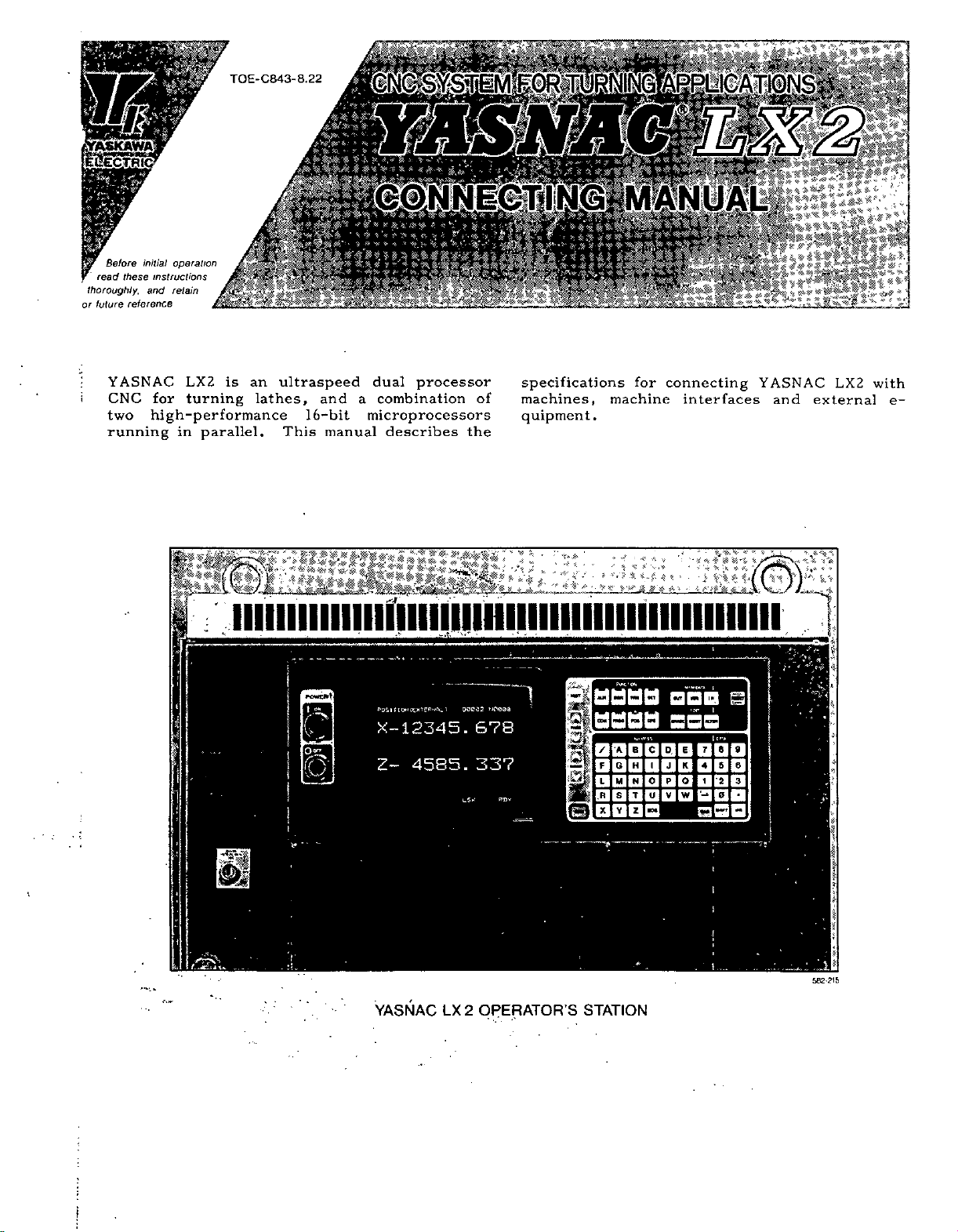
running
opera
/rw7/a/
instructions
these
and
retain
reference
YASNAC
CNC
for
two
high-performance
C«.««
ew
Sfcr#M
fV
&
BHP*
is
an
lathes,
LX2
turning
in
//on
parallel.
«Hiÿ:
iiiiiiiiiiiiiiiiiiiiiiiiiiiiiiiiiiiiiiiiiiiiiiiiii
*20;;
m
[ÿ#«
ultraspeed
and
16-bit
This
manual
“ÿk
:
!*
*«*
-»
'>
<v
»
«
«
If*
*****
i«gp?ti®§t
dual
processor
combination
a
microprocessors
describes
the
of
specifications
machines,
quipment.
for
"?
.*
«P
=
*
\-,*
connecting
interfaces
'
=
*;
4
imi'
machine
.•ÿ
•
•
‘V?
»
v
,»
*
*
YASNAC
and
LX2
external
with
e-
I:
a
‘
5
l
U
I
-
’
1
[,
rli
K
t
c:
[•E
PDSlflOMCEXTffPudi.)
X-12345.
4585.
Z-
QOP32
US*
ND000
678
337
ildfisaa
k
I
a
B
H
G
N
M
I
s
T
Y
z
ID
!ÿ
mo
C
O
U
(
\*m\
SBC
0
El
K
J
a
P
V
W|'-
9
8
7
5
6
4
1
2
1
3
O
!i
*ÿ
'•**.
OPERATOR’S
LX
YASNAC
2
STATION
582*215
:
;
;
Page 2

r
Page 3
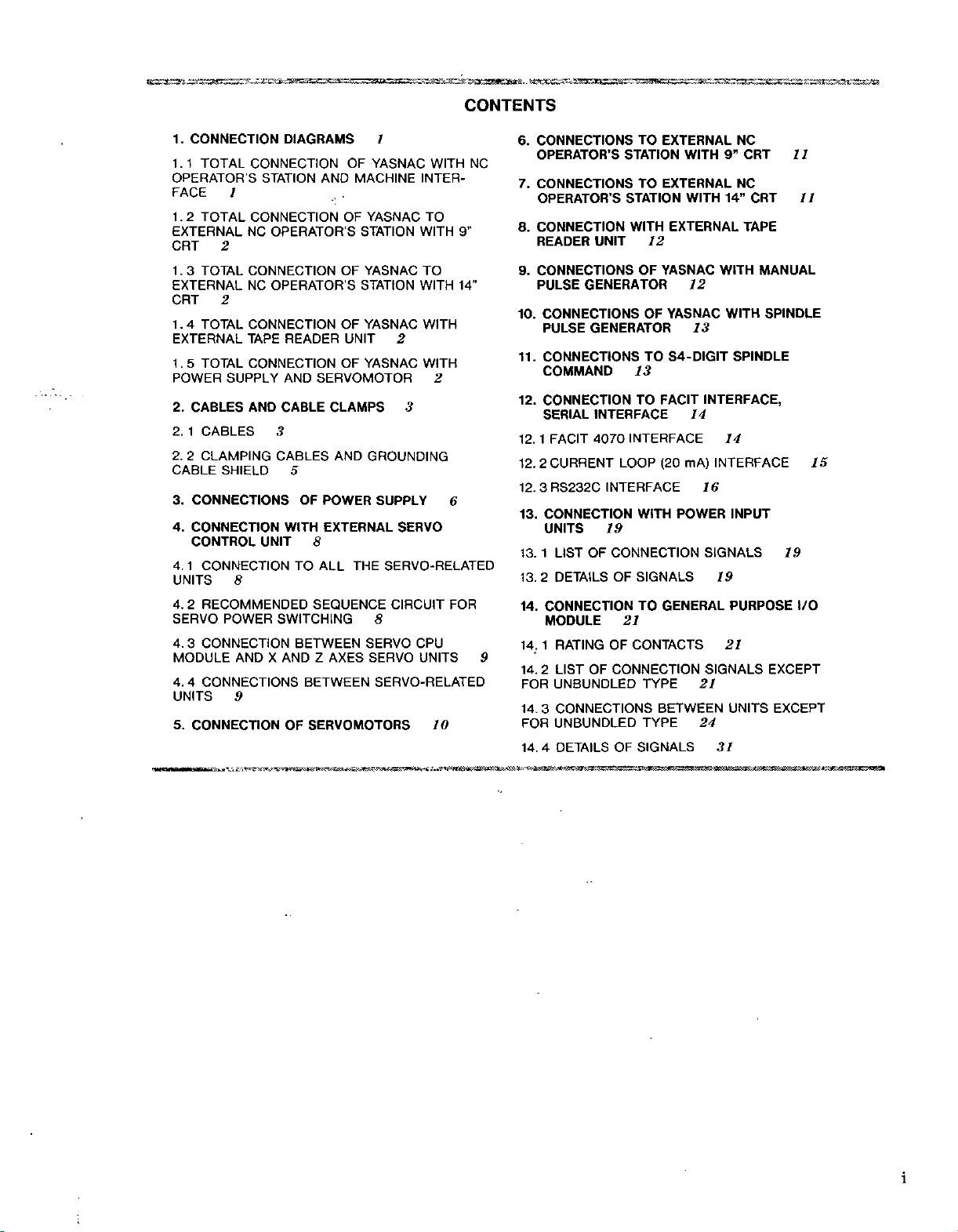
CONTENTS
1.
CONNECTION
1.1
TOTAL
OPERATOR'S
FACE
1.2
1
TOTAL
EXTERNAL
CRT
1
.
3
2
TOTAL
EXTERNAL
CRT
1
4
.
2
TOTAL
EXTERNAL
TOTAL
5
.
1
POWER
2.
2.
2.
CABLE
3.
4.
SUPPLY
CABLES
1
CABLES
2
CLAMPING
SHIELD
CONNECTIONS
CONNECTION
CONTROL
4.
1
CONNECTION
UNITS
4.
SERVO
4.
3
MODULE
4.
UNITS
5.
8
RECOMMENDED
2
POWER
CONNECTION
4
CONNECTIONS
9
CONNECTIONOFSERVOMOTORS
DIAGRAMS
CONNECTION
STATION
CONNECTION
NC
OPERATOR'S
CONNECTION
OPERATOR'S
NC
CONNECTION
TAPE
READER
CONNECTION
AND
AND
CABLE
3
CABLES
5
OF
WITH
UNIT
TO
SWITCHING
BETWEEN
ANDXAND
BETWEEN
OF
MACHINE
AND
OF
STATION
OF
STATION
OF
UNIT
OF
SERVOMOTOR
CLAMPS
AND
POWER
EXTERNAL
8
THE
ALL
SEQUENCE
AXES
Z
1
YASNAC
WITH
INTER¬
YASNAC
YASNAC
TO
WITH
TO
WITH
YASNAC
WITH
2
YASNAC
WITH
2
3
GROUNDING
SUPPLY
6
SERVO
SERVO-RELATED
CIRCUIT
8
SERVO
SERVO
FOR
CPU
UNITS
SERVO-RELATED
10
9”
14"
NC
TO
CONNECTIONS
6.
OPERATOR
CONNECTIONS
7.
S
OPERATOR’S
CONNECTION
8.
READER
CONNECTIONS
9.
PULSE
CONNECTIONS
10.
PULSE
CONNECTIONS
11.
UNIT
GENERATOR
GENERATOR
COMMAND
12.
CONNECTION
SERIAL
12.
1
12.
2
3
12.
13.
CONNECTION
UNITS
1
13.
13.
2
14.
CONNECTION
INTERFACE
FACIT
4070
CURRENT
RS232C
OF
LIST
DETAILS
INTERFACE
19
CONNECTION
OF
MODULE
9
LIST
2
14.
UNBUNDLED
FOR
14.
CONNECTIONS
3
UNBUNDLED
FOR
4
DETAILSOFSIGNALS
14.
RATING
1
14.
OF
CONNECTION
OF
EXTERNAL
STATION
EXTERNAL
TO
STATION
WITH
EXTERNAL
12
OF
YASNAC
YASNAC
OF
TO
S4-DIGIT
13
FACIT
TO
INTERFACE
(20
LOOP
WITH
SIGNALS
GENERAL
TO
21
CONTACTS
TYPE
BETWEEN
TYPE
WITH
WITH
12
mA)
POWER
NC
CRT
9”
NC
14”
TAPE
WITH
WITH
13
SPINDLE
INTERFACE,
14
14
INTERFACE
16
INPUT
SIGNALS
19
PURPOSE
21
SIGNALS
21
UNITS
24
31
CRT
MANUAL
SPINDLE
EXCEPT
EXCEPT
11
11
15
19
I/O
i
i
Page 4
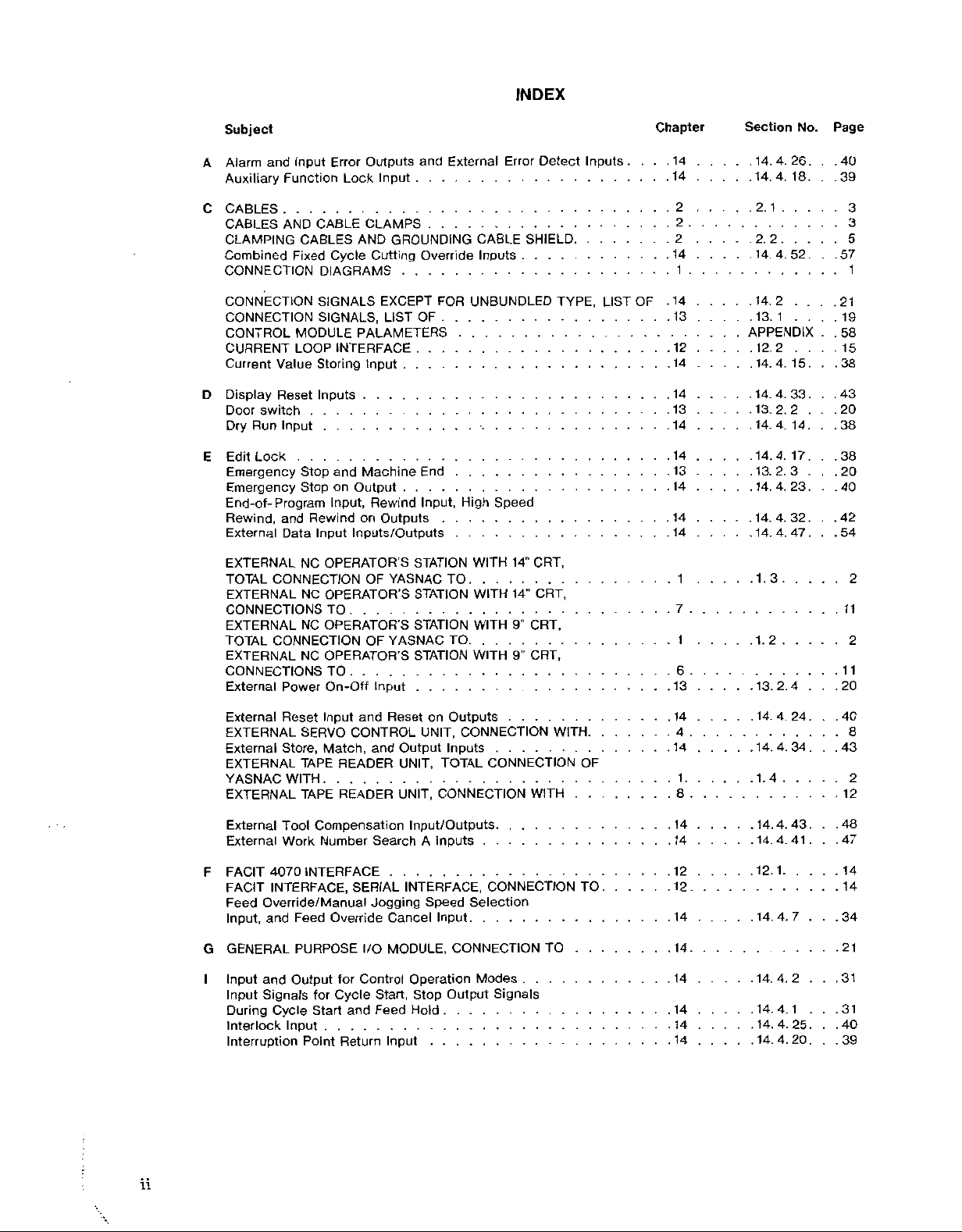
INDEX
Subject
and
Alarm
A
Auxiliary
C
CABLES
CABLES
CLAMPING
Combined
CONNECTION
CONNECTION
CONNECTION
CONTROL
CURRENT
Current
Display
D
Door
switch
Dry
Run
Edit
E
Lock
Emergency
Emergency
End-of-
Rewind,
External
EXTERNAL
TOTAL
EXTERNAL
CONNECTIONS
EXTERNAL
TOTAL
EXTERNAL
CONNECTIONS
External
Input
Error
Function
AND
Fixed
MODULE
LOOP
Value
Reset
Input
Program
and
Data
CONNECTION
CONNECTION
Power
Lock
CABLE
CABLES
Cycle
DIAGRAMS
SIGNALS
SIGNALS,
INTERFACE
Storing
Inputs
Stop
and
Stop
on
Input,
Rewind
Inputs/Outputs
Input
NC
OPERATOR’S
NC
OPERATOR’S
TO
OPERATOR'S
NC
OPERATOR'S
NC
TO
On-Off
Outputs
CLAMPS
AND
Cutting
PALAMETERS
and
Input
GROUNDING
Override
EXCEPT
OF
LIST
....
Input
.
.
.
Machine
Output
Rewind
on
OF
OF
Input
End
Input,
Outputs
STATION
YASNAC
STATION
STATION
YASNAC
STATION
External
CABLE
Inputs
FOR
UNBUNDLED
.
.
.
High
WITH
TO
WITH
WITH
TO
WITH
Error
Speed
14"
14”
9”
9"
Detect
SHIELD.
TYPE,
CRT,
CRT,
CRT,
CRT,
Inputs
LIST
.
Chapter
. .
OF
.....
.14
14
2
2
2
14
1 1
.
.14
13
Section
14.4.26.
14.
2.
2.
14
.
.
.14.2
13.
APPENDIX
.
. .
12
14
.....
.14
.
13
14
14
.13
.....
14
.
.14
.....
14
1
7
1
6
13
12.2
14.
14.4.33.
13.
14.
14.4.
13.
14.
14.4.32.
14.
1.
1.
13.2.4
Page
No.
.
.40
4.
18
1
2
4.
52
1
4.
15
2.
2
14
4.
17
2.3
23
4.
4.
47
3
2
39
3
3
5
57
.
.
.
.21
19
.
.58
15
38
.
.43
20
38
38
.
.20
.
40
.
.42
54
2
11
2
11
20
External
EXTERNAL
External
EXTERNAL
YASNAC
EXTERNAL
External
External
F
FACIT
FACIT
Feed
Input,
G
GENERAL
I
Input
Input
During
Interlock
Interruption
Input
Reset
SERVO
Match,
Store,
TAPE
WITH
Tool
Work
4070
INTERFACE,
Override/Manual
and
Output
and
Signals
Cycle
Input
READER
TAPE
READER
Compensation
Number
INTERFACE
Feed
Override
PURPOSE
for
Cycle
for
Start
Point
Return
and
Reset
CONTROL
and
Search
SERIAL
Jogging
Cancel
MODULE,
I/O
Control
Start,
Feed
and
Input
Outputs
on
UNIT,
Output
UNIT,
UNIT,
Inputs
TOTAL
CONNECTION
Input/Outputs.
Inputs
A
INTERFACE,
Speed
Input
CONNECTION
Operation
Stop
Output
Hold
CONNECTION
CONNECTION
WITH
.
.
.
.
.
.
CONNECTION
Selection
.
Modes
.
Signals
WITH.
TO
.
OF
TO
4
14
4
14
1
.
8
.14
.
.....
14
12
12
14
14
14
.
.
.14
.
.....
.
.....
.14
14
14.
4.
14.
1.
4
14.4.43.
14.
4.41
12.1
14.4.7
14.4.2
14.4.1
14.4.25.
14.
4.
24
34
20
40
8
43
2
12
.48
.
47
14
14
.
34
21
31
.31
.
.
.
.40
39
ii
Page 5
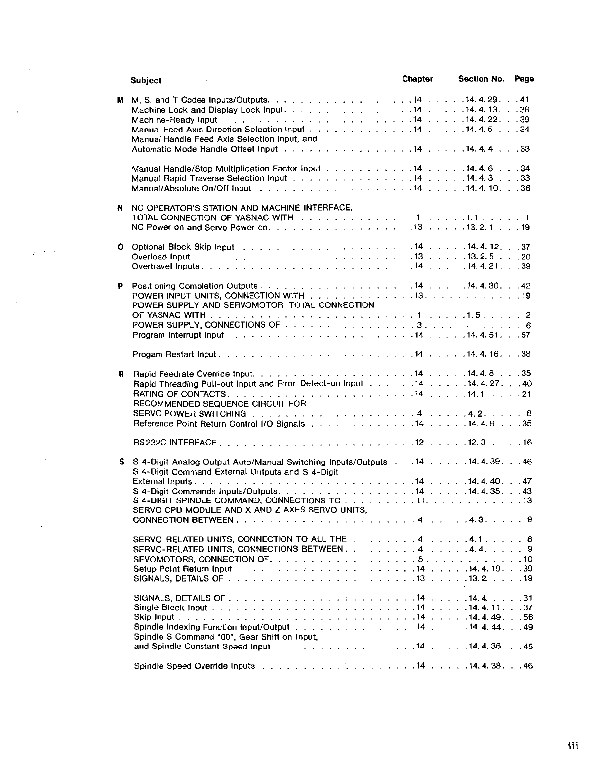
Subject
Chapter
Section
No.
Page
M,
S,
M
N
O
P
R
and
Machine
Machine-Ready
Manual
Manual
Automatic
Manual
Manual
Manual/Absolute
NC
TOTAL
NC
Optional
Overload
Overtravel
Positioning
POWER
POWER
OF
POWER
Program
Progam
Rapid
Rapid
RATING
RECOMMENDED
SERVO
Reference
Feed
Handle
Handle/Stop
Rapid
OPERATOR
CONNECTION
Poweronand
YASNAC
Feedrate
Threading
POWER
Codes
T
Lock
and
Axis
Mode
Traverse
Block
Input
Inputs
Completion
INPUT
SUPPLY
WITH
SUPPLY,
Interrupt
Restart
OF
CONTACTS
Point
Inputs/Outputs
Display
Input
Direction
Feed
Handle
On/Off
STATION
S
Servo
Skip
Selection
Axis
Offset
Multiplication
Selection
Input
YASNAC
OF
Power
Input
. . . .
UNITS,
Input
Override
Outputs
CONNECTION
SERVOMOTOR,
AND
CONNECTIONS
Input
Input
Pull-out
SEQUENCE
SWITCHING
Return
Input
Control
Lock
Selection
Input
AND
on
and
CIRCUIT
. . .
Input.
Input
Input,
....
Factor
Input
MACHINE
WITH
WITH
TOTAL
OF
Error
FOR
Signals
I/O
.
and
Input
.
.
INTERFACE,
CONNECTION
Detect-on
Input
14.
14
14
14
14
14
.14
.
.
.
.
.
.
.
.....
.
.14
.....
.
14
1
13
14
13
14
14
13
1
3
14
14
14
.....
.
.14
14
4
14
4.
14.
4.
14.4.
4.5
14.
4.4
14.
14.4.6
14.4.3
14.4.
1.1
2.
13.
14.4.
13.2.5
14.4.21
14.
4.
1.5
4.
14.
14.
4.
14.
4.8
14.4.27.
14.1
2
4.
14.4.9
29
13
22
10
1
12
30
51
16
41
38
39
34
33
.
.
.34
.
.
.33
36
1
19
37
20
39
42
19
2
6
57
38
35
.40
.
21
8
.
35
S
RS232C
S
S
External
S
S
SERVO
INTERFACE
4-Digit
4-Digit
Inputs
4-Digit
4-DIGIT
CPU
CONNECTION
SERVO-RELATED
SERVO-RELATED
SEVOMOTORS,
Setup
Point
SIGNALS,
SIGNALS,
Single
Block
Skip
Input
Spindle
Spindle
and
Spindle
Indexing
S
Spindle
Speed
Analog
Command
Commands
Output
SPINDLE
MODULE
BETWEEN
UNITS,
UNITS,
CONNECTION
Return
DETAILS
DETAILS
Input
Function
Command
Constant
Override
Auto/Manual
External
Inputs/Outputs
COMMAND,
ANDXAND
CONNECTION
CONNECTIONS
Input
OF
OF
Input/Output
"00",
Gear
Speed
Inputs
Outputs
Input
and
CONNECTIONS
AXES
Z
OF
Shift
on
Switching
4-Digit
S
SERVO
TO
ALL
BETWEEN
...
Input,
.
.
Inputs/Outputs
TO
...
UNITS,
THE
.
12
.
14
.....
.
.
.14
.
.
.....
14
1
1
4
4
.
.
.....
4
5
14
13
14
14
.
.....
.14
14
14
14
12.3
14.4.39.
14.4.40.
14.4.35
4.3
1
4.
4.
4
19
14.4.
13.2
14.4.
11
14.
4.
14.4.49...56
4.
44
14.
36
14.
4.
14.4.38
16
.46
.
.
.47
43
13
9
8
9
10
.
39
19
.
31
37
49
45
46
iii
Page 6
INDEX
(Cont’d)
Subject
Spindle
S
T
U
Stored
Time
Tool
Tool
Tool
Travel
UNITS
Stroke
Count
Life
Set
Wear
on
EXCEPT
CONNECTIONS
User
Macro
X
X-Axis
Y
YASNAC
CONNECTIONS
YASNAC
CONNECTIONS
Speed
Limit
Input
Control
Compensation
Error
Compensation
Thread
and
Input/Output
Image
Mirror
WITH
WITH
Input
Reach
by
3
Inputs/Outputs
Cutting
UNBUNDLED
FOR
BETWEEN
Input
MANUAL
OF
SPINDLE
OF
Inputs/Outputs.
Tool
Inputs
Input
on
Function.
PULSE
PULSE
....
.
.
.
Outputs
TYPE,
.
.
.
GENERATOR,
GENERATOR,
Chapter
.14
.
.....
14
.14
.
.
.14
.14
.
.
.14
14
14
14
14
9
10.
Section
14.4.37.
4.
14.
.14.4.
4.
.14.
.14.4.50.
.14.4.53.
.14.
4.31.
14.3
14.
4.
4.
14.
45
42.
48.
.
46
28
No.
.
Page
.46
53
48
.
.55
.57
.57
42
24
54
41
12
13
iv
Page 7
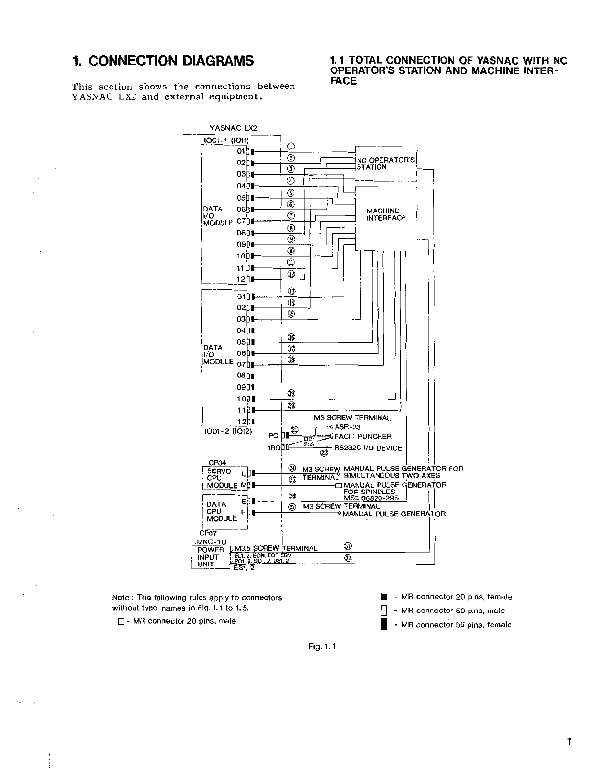
1.
CONNECTION
LX2
shows
and
This
section
YASNAC
DIAGRAMS
connections
the
external
equipment.
between
1.
1
TOTAL
CONNECTION
OPERATOR’S
FACE
STATION
OF
AND
YASNAC
MACHINE
WITH
INTER¬
NC
YASNAC
7001-1
DATA
MODULE
I
DATA
I/O
MODULE
1001-2
CP04
|“SERVO
!
CPU
|
MODULE
r~
DATA
!
CPU
|
MODULE
CP07
JZNC-TU
POWFR
I
IMpUT
UNIT
l
LX2
(I011)
-5ib«-
02j]|-
03p»—
04.31-
05
06
31-
07D»-
08(31-
09D*
iopi-
023*
03]*-
04
31
06
07[]|-
08
pi
09
31
10
1
1
pl-
-12P*
(1012)
"[W
r
MQI-
J
LM3.5
2,
PTl.
|
©
©
©
©
©
®
I
®
I
©
i
©
©
©
©
©
j
©
PO
Jl
IROUT"'255
©
®
I
—
©
I
©
_
SCREW
TERMINAL
ECM
EOF
EON.
C
J
SCREW
M3
o
/
ASR-33
-
FACIT
RS232C
©
SCREW
-
a
SCREW
MANUAL
SIMULTANEOUS
MANUAL
FOR
MS31
TERMINAL
0
MANUAL
©
©
M3
'
TERMINAL0
---
M3
OPERATORS]
NC
STATION
MACHINE
INTERFACE
!
TERMINAL
PUNCHER
I/O
DEVICE
PULSE
PULSE
SPINDLES
29S
06820-
PULSE
GENERATOR
TWO
GENERATOR
I
1
GENERATOR
AXES
FOR
Note:The
without
type
MR
-
following
names
connector
rules
in
20
Fig,
pins,
apply
1
1.
male
to
to
1.
connectors
5.
Fig.
1.1
-
MR
connector
MR
connector
-
[I
connector
MR
|
-
20
50
50
pins,
pins,
pins,
female
male
female
1
i
Page 8
OF
UNIT
EXTERNALLY
TAPE
1.
4
OF
CONTROL
®
SERVO
TO
ARMATURE
_TO
ARMATURE
YASNAC
READER
BASE
:
IG
TERMINAL
YASNAC
POWER
POWER
X-AXIS
Z-AXIS
SERVOMOTOR
SERVOMOTOR
WITH
PROVIDED
UNIT
WITH
4
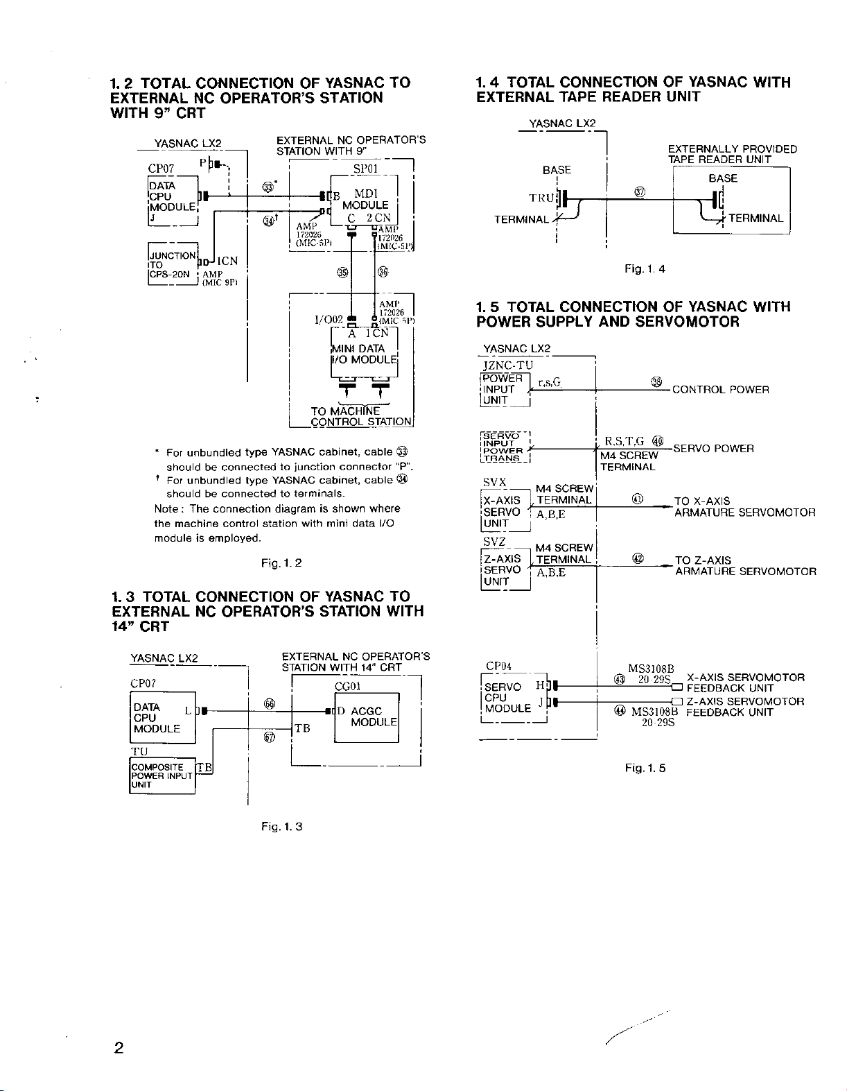
TOTAL
1.
2
EXTERNAL
WITH
9”
YASNAC
CP07
BATA
CPU
MODULE
[JUNCTION
ITO
|CPS-2QN
CONNECTION
NC
OPERATOR
CRT
LX2
i
i
X
r
HHlCN
AMP
;
9P)
{MIC
J
OF
STATION
S
EXTERNAL
STATION
WITH
i[Cr
AMP
172026
1/002
YASNAC
NC
MODULE
u
—
J
®
1
TO
OPERATOR’S
9”
SP01
2CN
—
DAMP
?
172026
i
|
MDI
C
©
AMI
i{Mic
sp!
r'AicNn
[MINI
DATA
T
STATION
cable
MP”.
@
cable
where
I/O
i
©
I/O
MODULE
:
_
type
type
YASNAC
to
YASNAC
to
diagram
station
1.2
Fig.
junction
terminals.
unbundled
For
*
shouldbeconnected
f
For
unbundled
be
:
The
connection
employed.
is
connected
control
should
Note
the
machine
module
MACHINE
TO
CONTROL
cabinet,
cabinet,
is
shown
with
mini
T
connector
data
TOTAL
1.
EXTERNAL
TERMINAL
5
1.
TOTAL
POWER
YASNAC
JZNC-TU
fPOWER“|
INPUT
UNIT
j
_
[SERVO
I
INPUT
'POWER
[TRANS
SVX
X-AXIS
SERVO
SVZ
Z-AXIS
i
SERVO
CONNECTION
TAPE
YASNAC
LX2
BASE
TKU|||
1
!
CONNECTION
SUPPLY
LX2
rsG
Jr
j
]
L
Jr
j
M4
SCREW
TERMINAL
A.B.E
SCREW
M4
TERMINAL
A,B,E
READER
1
Fig.
AND
R,S,T,G
,
7
SCREW
M4
TERMINAL
@
SERVOMOTOR
_
©
_
@
3
TOTAL
1.
EXTERNAL
14”
CRT
YASNAC
CP07
DATA
CPU
MODULE
COMPOSITE
POWER
INPUT
UNIT
CONNECTION
OPERATOR
NC
LX2
]»
L
TB
EXTERNAL
STATION
©
©
Fig.
1.3
OF
STATION
S
TB
YASNAC
NC
OPERATOR’S
WITH
14“
CG01
D
ACGC
MODULE
TO
WITH
CRT
1
CP04
!~SERVO
CPU
MODULE
HW
JP*
MS3108B
©
-
—
-
®
Fig.
20
29S
MS3108B
20
29S
5
1.
X-AXIS
a
FEEDBACK
Z-AXIS
FEEDBACK
SERVOMOTOR
UNIT
SERVOMOTOR
UNIT
2
Page 9
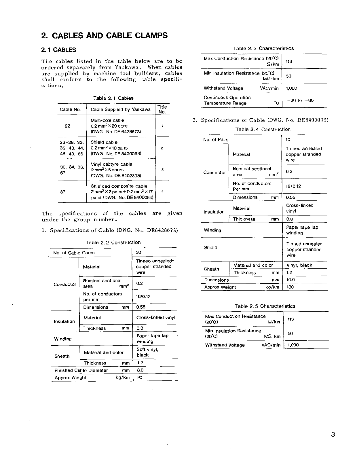
2.
CABLES
AND
CABLE
CLAMPS
2.1
CABLES
The
cables
ordered
supplied
are
shall
cations
The
conform
.
Cable
1-22
23-28,
35,
48,
30,
67
37
specifications
under
1.
Specifications
listed
separately
No.
33,
43,
49,
34, 36,
the
group
44,
66
by
to
in
from
machine
the
Table
Cable
-core
Multi
mm2
0.2
(DWG.
Shield
mm2
0.2
(DWG.
Vinyl
cabtyre
2
mm2
(DWG.
Shielded
2
mm2
(DWG.
pairs
of
number,
Cable
of
the
Yaskawa.
following
1
2.
Supplied
cable
X
20
DE
No.
cable
X10
DE
No.
x
cores
5
No.
DE
composite
pairs
X2
the
(DWG.
table
tool
Cables
by
.
core
6428673)
pairs
8400093)
cable
8402398)
+0.2
DE
No.
below
builders,
Yaskawa
cable
mm2
8400094)
cables
No.
are
When
cable
Title
No.
X17
are
DE6428673)
be
to
cables
cables
specifi¬
t
2
3
4
given
Max
Conduction
Min
Insulation
Withstand
Continuous
Temperature
2.
Specifications
of
No.
Conductor
Insulation
Winding
Pairs
Table
Resistance
Resistance
Voltage
Operation
Range
Table
Material
Nominal
area
No.
mm
Per
Dimensions
Material
Thickness
3
2.
Cable
of
2.
sectional
conductors
of
Characteristics
(20'C)
£2/km
(20"C)
M£2-km
VAC/min
•c
(DWG.
4
Construction
mm2
mm
mm
113
50
1,000
-30
+60
to
DE8400093)
No.
10
Tinned
annealed
copper
stranded
wire
0.2
16/0.12
0.55
Cross-linked
vinyl
0.3
Paper
tape
winding
lap
of
Cable
No.
Conductor
Insulation
Winding
Sheath
Finished
Approx
Cable
Weight
2.
Table
Cores
Material
Nominal
area
No.
of
conductors
per
mm
Dimensions
Material
Thickness
Material
Thickness
Diameter
2
Construction
sectional
color
and
kg/km
mm2
mm
mm
mm
mm
20
annealed-
Tinned
copper
stranded
wire
0.2
16/0.12
0.55
Cross-linked
0.3
tape
Paper
winding
vinyl,
Soft
black
1.2
8.0
90
lap
vinyl
Shield
Sheath
Dimensions
Weight
Approx
Conduction
Max
(20'C)
Insulation
Min
(20‘C)
Withstand
Material
Thickness
Table
Resistance
Voltage
and
5
2.
Characteristics
Resistance
color
mm
mm
kg/km
£2/km
MQ-km
VAC/min
Tinned
copper
wire
Vinyl,
1.2
10.0
130
113
50
1,000
annealed
stranded
black
3
Page 10
1
2.
CABLES
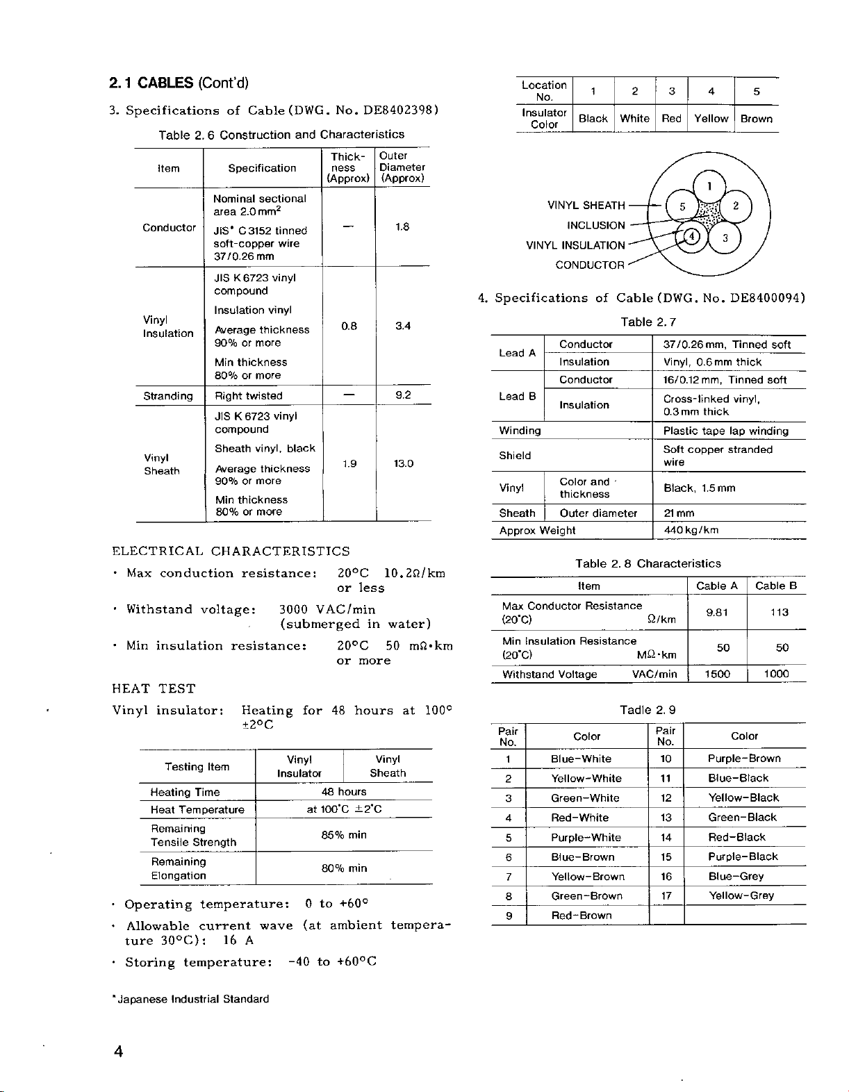
3.
Specifications
Table
item
Conductor
Vinyl
Insulation
Stranding
Vinyl
Sheath
ELECTRICAL
•
•
•
HEAT
Vinyl
•
•
•
conduction
Max
Withstand
Min
insulation
TEST
insulator:
Testing
Heating
Heat
Remaining
Tensile
Remaining
Elongation
Operating
Allowable
30°C):
ture
Storing
(Cont'd)
of
Cable
2.6
Construction
Specification
Nominal
area
2.0
C3152
JIS"
soft-copper
37/0.26
K6723
JIS
compound
Insulation
Average
90%
or
thickness
Min
80%
or
Right
twisted
6723
JIS
K
compound
Sheath
Average
90%
or
thickness
Min
or
80%
CHARACTERISTICS
resistance:
voltage:
resistance:
Heating
±2°C
Item
Time
Temperature
Strength
temperature:
current
16
A
temperature:
(DWG.
sectional
mm2
tinned
wire
mm
vinyl
vinyl
thickness
more
more
vinyl
vinyl,
black
thickness
more
more
3000
(submerged
Vinyl
Insulator
wave
-40
No.
Characteristics
and
Thick¬
ness
(Approx)
0.8
20°C
or
VAC/min
20°C
or
48
for
hours
48
100"C
at
85%
80%
+60°
to
0
(at
ambient
+60°C
to
DE8402398)
1.9
less
in
more
hours
Vinyl
Sheath
±2'C
min
min
Outer
Diameter
(Approx)
1.8
3.4
9.2
13.0
10.2fi/km
water)
mOkm
50
at
tempera¬
100°
Location
Insulator
Color
VINYL
Specifications
4.
A
Lead
Lead
B
Winding
Shield
Vinyl
Sheath
Approx
Conductor
Max
(20"C)
Insulation
Min
(20"C)
Withstand
Pair
No.
1
2
3
4
5
6
7
8
9
No.
Black
VINYL
SHEATH
INCLUSION
INSULATION
CONDUCTOR
Conductor
Insulation
Conductor
Insulation
Color
thickness
Outer
Weight
Table
Item
Resistance
Voltage
Color
Blue-White
Yellow-White
Green-White
Red-White
Purple-White
Blue-Brown
Yellow-Brown
Green-Brown
-Brown
Red
1
White
of
Cable
Table
and
diameter
2.8
Resistance
Tadle
3
2
Red
LML2
4
(DWG.
7
2.
37/0.26
Vinyl,
16/0.12
Cross-linked
mm
0.3
Plastic
copper
Soft
wire
Black,
21
mm
kg
440
Characteristics
Q/km
MQ
-km
VAC/min
9
2.
Pair
No.
10
11
12
13
14
15
16
17
4
Yellow
1
:-s
3
DE8400094)
No.
mm,
Tinned
0.6mm
thick
mm,
Tinned
vinyl,
thick
lap
tape
stranded
1.5
mm
/km
A
Cable
9.81
50
1500
Color
Purple-Brown
Blue-Black
Yellow-Black
Green-Black
Red
-Black
Purple-Black
Blue-Grey
Yellow-Grey
5
Brown
winding
Cable
soft
soft
B
113
50
1000
"Japanese
4
Industrial
Standard
Page 11
\
GROUNDPLATE
CLAMP
CABLE
SHIELD
i
ENCLOSURE
i
15
14
13
16
12
Table
11
17
\
@
[WHITE
10
2.
1
RED
BLUE
I
10
JT
9
Cable
2
3
4
7
8
Supplied
A
CABLE
INCLUSION
5
6
by
Machine
CABLE
WINDING
LAP
SHIELD
SHEATH
B
CABLE
SHIELD
B
ENCLOSURE
CABLE
CLAMP
S
E
E
GROUND-
PLATE
-E-
CABLE
CABLE
$
Builders
Specifications
No.
Cable
31,
32,
46,
47
38, 39,
57,
60
65
58,
59,
42,
41,
40,
52,
56
cable
The
pending
2
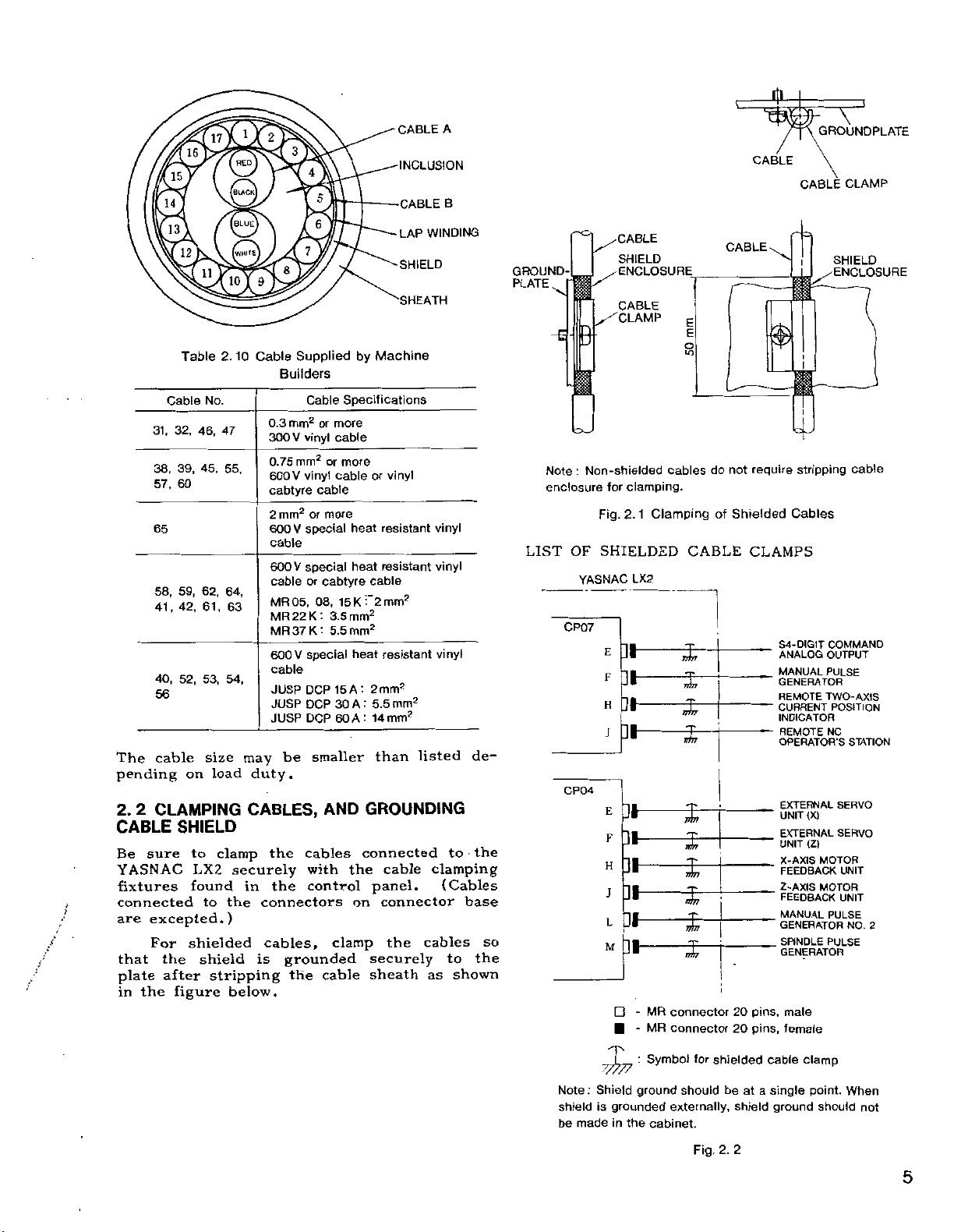
2.
CLAMPING
CABLE
Be
SHIELD
sure
YASNAC
fixtures
t
f
connected
excepted.)
are
For
the
that
after
plate
the
in
figure
55,
45,
62,
61,
53,
size
load
on
to
clamp
LX2
found
to
shielded
shield
stripping
64,
63
54,
may
duty.
CABLES,
securely
in
the
is
below.
Cable
mm2
0.3
vinyl
V
300
mm2
0.75
vinyl
V
600
cabtyre
or
2
mm2
special
V
600
cable
special
V
600
or
cable
05,
MR
MR22K
MR
37
K
V
special
600
cable
DCP
JUSP
JUSP
DCP
DCP
JUSP
be
cables
the
with
control
the
connectors
cables,
grounded
the
or
more
cable
more
or
cable
cable
more
cabtyre
08,
15
:
3.5
'
5.5
15
30
60
smaller
AND
the
clamp
cable
vinyl
or
resistant
heat
heat
resistant
cable
2
mm2
K
mm2
mm2
resistant
heat
:
mm2
2
A
A:
mm2
5.5
:
14
A
mm2
listed
than
GROUNDING
connected
the
clamping
cables
as
panel.
on
securely
sheath
cable
connector
vinyl
vinyl
vinyl
to
(Cables
to
shown
de¬
the
base
the
so
Note
enclosure
LIST
:
Non-shielded
Fig.
OF
SHIELDED
YASNAC
CP07
E
F
H
CP04
M
for
J
E
F
H
J
L
clamping.
Clamping
1
2.
LX2
MR
-
MR
-
cables
CABLE
i
s-1
3—
connector
connector
do
not
of
r
require
Shielded
CLAMPS
pins,
20
pins,
20
i
stripping
Cables
X-AXIS
male
female
COMMAND
OUTPUT
PULSE
TWO-AXIS
NC
(X)
<Z)
MOTOR
MOTOR
PULSE
PULSE
POSITION
S4-DIGJT
ANALOG
MANUAL
GENERATOR
REMOTE
CURRENT
INDICATOR
REMOTE
OPERATOR
EXTERNAL
UNIT
EXTERNAL
UNIT
FEEDBACK
Z-AXIS
FEEDBACK
MANUAL
GENERATOR
SPINDLE
GENERATOR
cable
S
STATION
SERVO
SERVO
UNIT
UNIT
NO.
2
Note
:
shield
be
madeinthe
x
Shield
grounded
is
:
Symbol
ground
cabinet.
for
should
externally,
Fig.
shielded
be
at
shield
2.
2
cable
a
single
ground
clamp
point.
should
When
not
5
Page 12
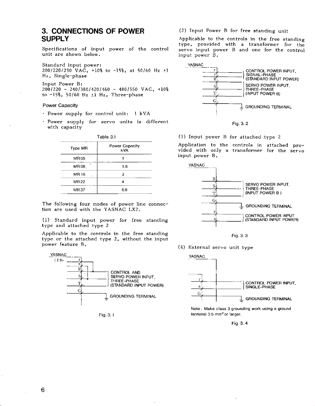
3.
CONNECTIONS
SUPPLY
Specifications
unit
are
shown
of
input
below.
OF
power
POWER
of
the
control
(2)
Input
Applicable
type,
servo
input
input
power
Power
to
provided
the
power
B.
B
for
controls
with
B
free
in
a
transformer
and
standing
the
one
for
free
unit
standing
the
for
control
the
Standard
200/220/230
Hz,
Single-phase
Input
Power
200/220
-15%,
to
•
•
Power
Power
with
following
are
Standard
and
Capacity
capacity
used
Power
The
tion
(1)
type
Applicable
the
or
type
power
feature
YASNAC
1TB-
VAC,
power:
+10%
input
B:
240/380/420/460
Hz
MR
05
08
15
22
37
four
with
for
±1
control
for
modes
the
50/60
supply
supply
Type
MR
MR
MR
MR
MR
input
attached
to
attached
the
type
controls
B.
r
to
Hz,
servo
Table
YASNAC
power
2
type
-15%,
-
at
480/550
Three-phase
unit:
units
3.1
Capacity
Power
kVA
1
1.6
3
4
6.9
of
power
LX2.
for
the
in
without
2,
1
free
free
50/60
VAC,
kVA
is
line
Hz
different
connec¬
standing
standing
the
input
±1
+10%
YASNAC
(3)
Input
Application
vided
input
(4)
with
power
YASNAC
External
YASNAC
1
S,
III
power
to
only
B.
R
S_ÿ
T
Gl,
r
f
servo
B
the
a
1
Fig.
3.
for
attached
controls
transformer
I.
Fig.
3.
unit
type
CONTROL
SIGNAL-PHASE
(STANDARD
SERVO
(INPUT
GROUNDING
2
POWER
POWER
type
in
POWER
INPUT
attached
for
SERVO
POWER
(INPUT
POWER
GROUNDING
CONTROL
(STANDARD
3
POWER
INPUT
INPUT,
POWER)
INPUT,
B)
TERMINAL
2
the
INPUT,
)
B
TERMINAL
INPUT
POWER)
pro¬
servo
%
4
Tt
Gl
CONTROL
SERVO
'
THREE-PHASE
(STANDARD
GROUNDING
X
Fig.
3.
1
AND
POWER
INPUT
TERMINAL
INPUT,
POWER)
Note:Make
terminal
1
r
s
G
3
class
larger.
mm2
3.5
or
X
grounding
Fig.
3.
CONTROL
SINGLE-PHASE
GROUNDING
4
usingaground
work
POWER
INPUT,
TERMINAL
6
Page 13
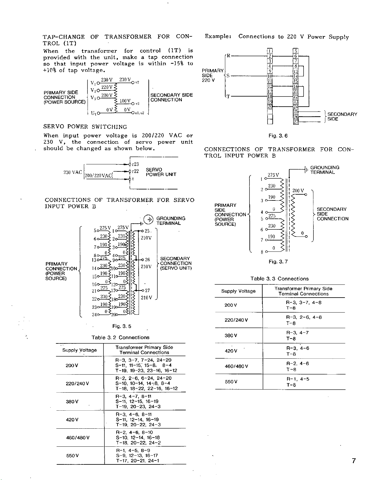
TAP-CHANGE
that
of
V,
(IT)
the
with
input
tap
SIDE
SOURCE)
POWER
input
the
be
TROL
When
provided
so
+10%
PRIMARY
CONNECTION
(POWER
SERVO
When
230
should
OF
transformer
the
power
voltage,
V,0
v2o
V30
I
uto
SWITCHING
power
connection
changed
TRANSFORMER
for
unit,
make
voltage
230
230
220
200
-
ov
voltage
V
V
V
V
100V
0
Ov2
O
V
-Oul.u2
is
of
shown
as
control
a
is
v2
.
200/220
servo
below.
tap
within
FOR
CON¬
(IT)
connection
-15%
SECONDARY
CONNECTION
VAC
power
SIDE
unit
Example:
is
to
PRIMARY
SIDE
220
or
CONNECTIONS
TROL
Connections
to
220
V
Power
Supply
[I]
R
J
S
V
1
10
H
13
ii
T
1
15
0
P
23
25
26
27
3.
6
SECONDARY
SIDE
FOR
CON¬
INPUT
OF
POWER
IS
Fig.
TRANSFORMER
B
VAC
230
CONNECTIONS
INPUT
PRIMARY
CONNECTION
(POWER
SOURCE)
POWER
Supply
200
220/240
380
420
460/480
550
.
V
V
V
V
200/220VACI
OF
TRANSFORMER
«|>r22
t
B
V
So™*
275
1
Ca230i2o230'
7Q19O|CC19Q*
o
:i
11'
gw
,17<
;n
Fig.
3.2
73
230
190:
275
i9o:
3.
5
Connections
Transformer
Terminal
3-7,
R-3,
11-15,'
S-11,
T-19,
19-23,
2-6,
R-2,
10-14,
S-10,
18-22,
T-18,
R-3,
4-7,
S-11,
12-15,
T-19,
20-23,
R-3,
4-6,
12-14,
S-11,
T-19,
20-22,
R-2,
4-6,
12-14,
S-10,
T-18,
20-22,
4-5,
R-1,
S-9,
12-13,
20-21,
T—
17,
130ÿÿ9,
230
U
190
15'
16'
275
21
22o230|igt>230
190
23
24ÿ20&_o
Table
Voltage
V
V
SERVO
POWER
FOR
GROUNDING
TERMINAL
25-
210V
SECONDARY
26
-CONNECTION
2I0V
210V
Connections
7-24,
6-24,
8-11
8-11
8-9
27
Primary
15-8,
23-16,
14-8,
22-16,
16-19
24-3
16-19
24-3
8-10
16-18
24-2
16-17
24-1
(SERVO
J
24-20
8-4
24-20
8-4
UNIT
Side
16-12
16-12
SERVO
UNIT)
PRIMARY
SIDE
CONNECTION
(POWER
SOURCE)
Supply
Voltage
V
200
220/240
V
380
420
V
460/480
V
550
V
V
-
Table
275
o
1
o
2
&
3
O
4
o
5
o
6
190
o
7
o
8
3.3
V
230
190
275
230
0
Fig.
3.
Connections
Transformer
Terminal
rH"
200
V
0
7
Connections
R-3,
3-7.
8
T—
R-3,
2-6,
T-8
R-3,
4-7
T-8
4-6
R-3,
T-8
R-2,
4-6
T-8
4-5
R-1,
T-8
GROUNDING
TERMINAL
SECONDARY
SIDE
*
CONNECTION
Primary
4-8
4-8
Side
7
Page 14
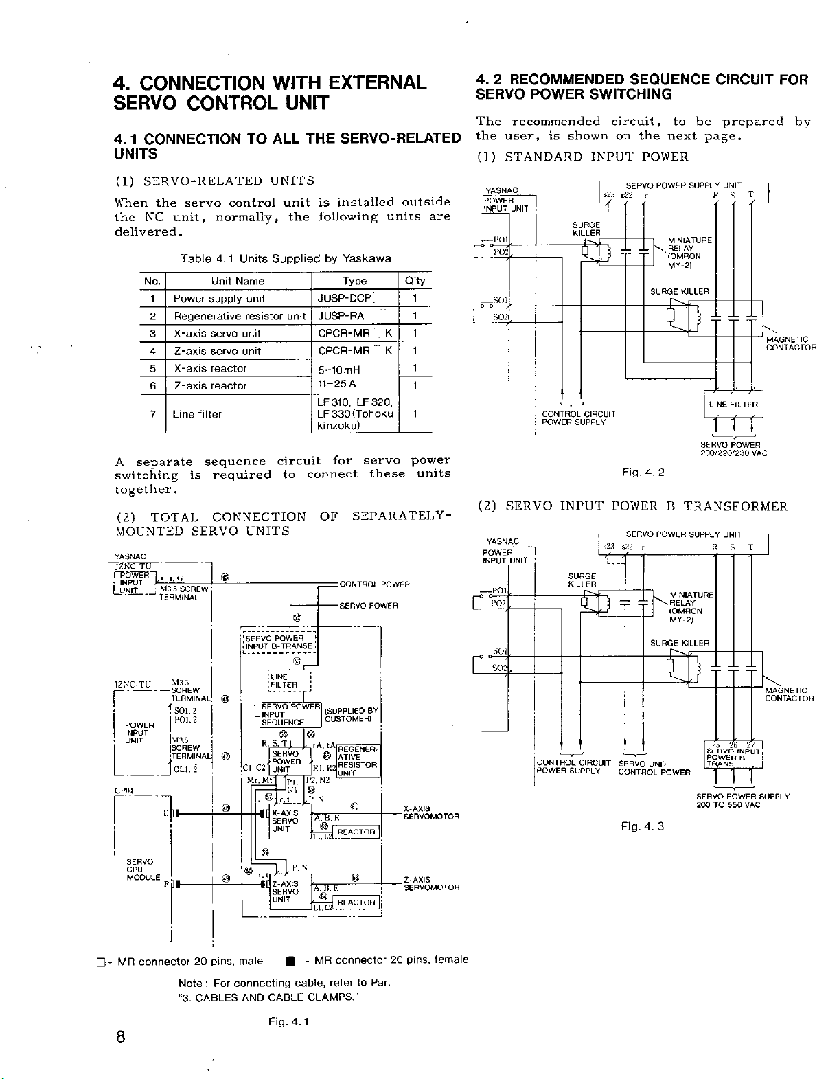
4.
CONNECTION
SERVO
4.1
CONNECTION
CONTROL
UNITS
TO
WITH
UNIT
ALL
THE
EXTERNAL
SERVO-RELATED
4.
2
RECOMMENDED
SERVO
The
the
(1)
POWER
recommended
user,
STANDARD
is
SWITCHING
circuit,
shown
on
INPUT
SEQUENCE
be
to
the
next
POWER
CIRCUIT
prepared
page.
FOR
by
(1)
SERVO-RELATED
When
the
the
NC
unit,
delivered.
Table
No.
1
Power
Regenerative
2
3
X-axis
Z-axis
4
5
X-axis
Z-axis
6
7
Line
A
separate
switching
together.
(2)
TOTAL
MOUNTED
YASNAC
TU
JZNC
fPOWEFn
•
INPUT
UNIT
L
JZNC-TU
f
POWER
INPUT
UNIT
Cl>fl4
SERVO
CPU
MODULE
(i
T.
S.
y
M3.5
TERMINAL
M3
-
SCREW
—
|
TERMINAL
SOI.
POl.
|\13.5
SCREW
0L1.
J
SCREW
servo
control
normally,
4.
1
Unit
supply
servo
servo
reactor
reactor
filter
sequence
is
required
CONNECTION
SERVO
©
3
@
2
2
®
2
j
©
©
Units
Name
unit
resistor
unit
unit
UNITS
'SERVO
.
INPUT
;
CLC2
--
Mr.
L_
UNITS
unit
Supplied
circuit
to
POWER
B-TRANSE
:ilNE
:FILTER
‘rr
SERVO
INPUT
SEQUENCE
©
S,
T
R.
SERVO
j
POWER
UNIT
Mt
]P1
|
©
r,
X-AXIS
SERVO
UNIT
©
n
r.t
|[
Z-AXIS
SERVO
I
UNIT
installed
is
following
the
by
Yaskawa
Type
JUSP-DCP
JUSP-RA
unit
CPCR-MR.
.
CPCR-MR
5-10mH
A
11-25
LF
310,LF320,
(Tohoku
330
LF
kinzoku)
servo
for
connect
OF
©
|
.
I
i
POWER
(SUPPLIED
CUSTOMER)
©
.
tA
TA.
_
©_
R1.R2
N2
P2.
NI
©
t
P
N
'
B,
A.
L1.L2
N
P.
'
A.
H.
-
©
Jini-REACTQR
these
SEPARATELY-
CONTROL
POWER
SERVO
BY
REGENER-
ATIVE
RESISTOR
UNIT
©
K
REACTOR
©
E
I
1*
li
outside
units
Q’ty
K
K
POWER
X-AXIS
SERVOMOTOR
Z-AXIS
SERVOMOTOR
are
1
1
1
1
1
1
1
power
units
POWER
INPUT
«
O
—
f—
L
—
Hi
(2)
POWER
INPUT
-
|~°
-
Hi
YASNAC
UNIT
POl
0—7
roz
SOI
SERVO
YASNAC
UNIT
POl,
P02
SOI
I
!
CONTROL
POWER
INPUT
1
CONTROL
POWER
SURGE
KILLER
SB
CIRCUIT
SUPPLY
SURGE
KILLER
£5
CIRCUIT
SUPPLY
SERVO
s2li
s22
Fig.
POWER
SERVO
s23
s22
Y72
=b
SERVO
CONTROL
Fig.
POWER
r
MINIATURE
-L
RELAY
\
--
(OMRON
MY-
--
SURGE
S5
4.
2
B
POWER
r
W
MINIATURE
\
dr
RELAY
(OMRON
MY-
SURGE
UNIT
POWER
3
4.
UNIT
SUPPLY
2)
KILLER
R
LINE
S
FILTER
T
MAGNETIC
CONTACTOR
TTT
SERVO
POWER
200/220/230
VAC
TRANSFORMER
SUPPLY
UNIT
R
S
T
2)
KILLER
MAGNETIC
CONTACTOR
25
27
26
SERVO
INPUT
POWER
B
TRANS.
TTT
POWER
VAC
SUPPLY
SERVO
200TO550
-
I
MR
8
i
connector
i
pins,
20
Note:For
"3.
CABLES
male
connecting
CABLE
AND
Fig.
MR
-
cable,
CLAMPS.”
4.1
connector
to
refer
Par.
20
pins,
female
Page 15
3
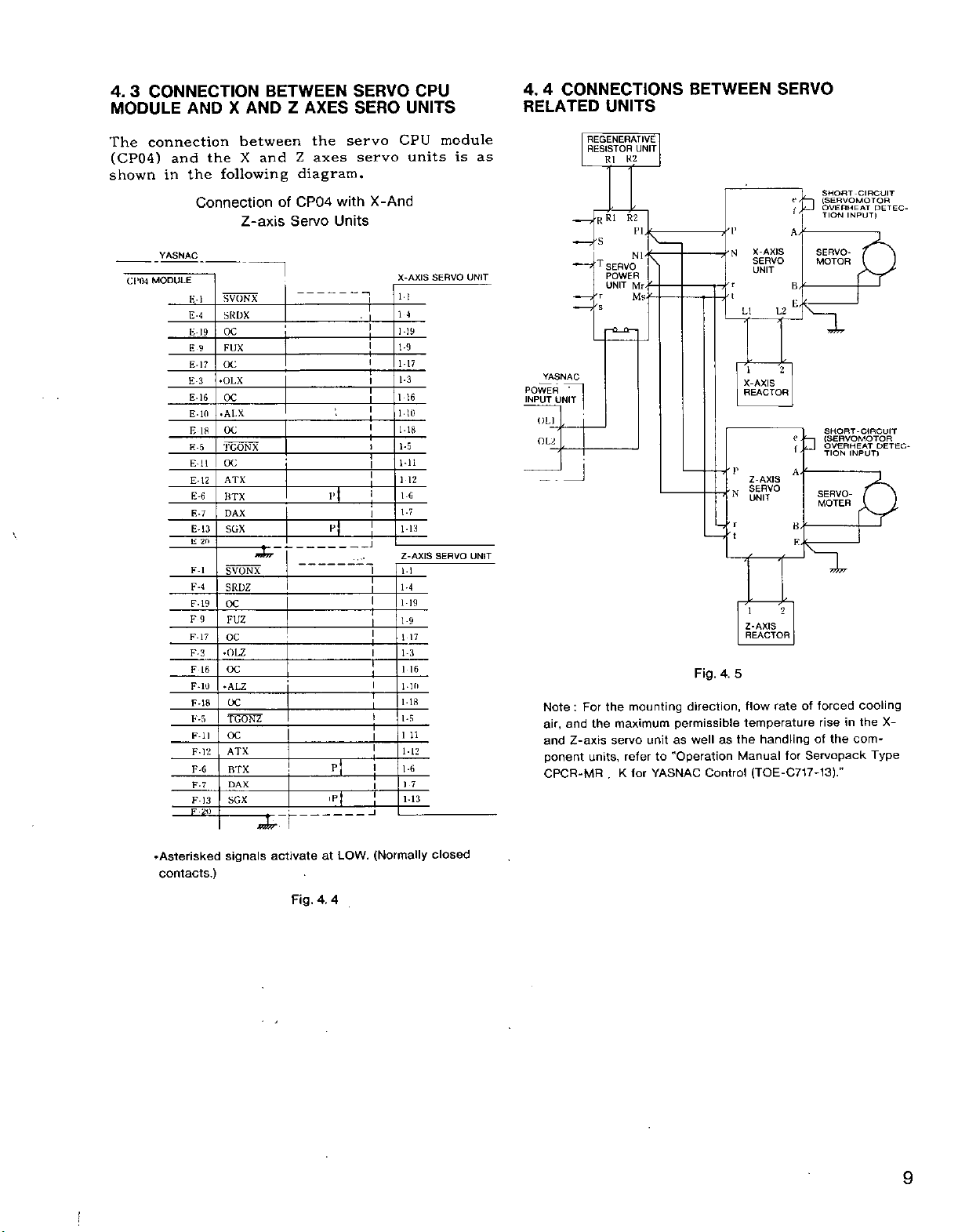
4.
CONNECTION
MODULE
AND
BETWEEN
X
AND
Z
AXES
SERVO
SERO
CPU
UNITS
4
CONNECTIONS
4.
RELATED
UNITS
BETWEEN
SERVO
module
servo
X-And
-I
CPU
units
X-AXIS
11
14
1-19
1-9
1-17
1-3
l
16
110
1-18
1-5
Ml
1
12
l-G
1-7
1-13
Z-AXIS
11
1-4
1-19
1-9
17
1
1-3
16
1
110
118
1-5
1
11
1-12
1-6
17
M3
SERVO
SERVO
is
as
UNIT
POWER
]NPUT
OLl
OL
UNIT
the
The
connection
(CP04)
shown
\
CP04
and
in
VASNAC
MODULE
the
K-
E-4
E-
E
E-
E-3
E-
E10
E
E-5
E-l
E-12
E-6
E-7
E-
E
F-l
F-4
F
F
F-17
F-3
F
F-10
F-18
K-5
F-ll
F
between
the
X
following
Connection
Z-axis
SVONX
1
SRDX
OC
19
FUX
9
OC
17
OLX
•
16
OC
ALX
•
OC
18
TCP
NX
OC
1
ATX
BTX
DAX
13
SGX
20
SVONX
SRDZ
19
OC
9
FUZ
OC
OLZ
•
OC
16
•ALZ
OC
TGONZ
OC
ATX
F-12
F-6
BTX
DAX
F-7
SGX
F-
13
and
Z
diagram.
CP04
of
Servo
servo
axes
with
Units
3
jT
Tp[
REGENERATIVE
RESISTOR
YASNAC
~
1
UNIT
Note:For
air,
and
and
Z-axis
units,
ponent
CPCR-MR
K1
-RR1
'S
T
SERVO
POWER
UNIT
T
's
the
the
.
UNIT
K2
R2
PI.
Nl'ÿT
Mr--
Ms.
mounting
maximum
unitaswell
servo
refer
for
K
direction,
permissible
"Operation
to
YASNAC
Fig.
Control
X-AXIS
SERVO
UNIT
LI
1
X-AXIS
REACTOR
Z-AXIS
SERVO
VN
UNIT
r
'
Z-AXIS
REACTOR
5
4.
flow
temperature
handling
the
as
Manual
(TOE-C717-13)."
L2
2
2
rate
for
SHORT-CIRCUIT
(SERVOMOTOR
|
OVERHEAT
f
'
A/
SERVO¬
MOTOR
B/ÿ
SERV
MOTE
forced
of
rise
of
Servopack
INPUT)
TION
SHORT-CIRCUIT
(SERVOMOTOR
OVERHEAT
INPUT)
TION
O-
:R
cooling
the
in
the
com¬
DE
DE
X-
Type
TEC-
TEC-
.Asterisked
contacts.)
signals
activate
Fig.
(Normally
LOW.
at
4.
4
closed
9
Page 16
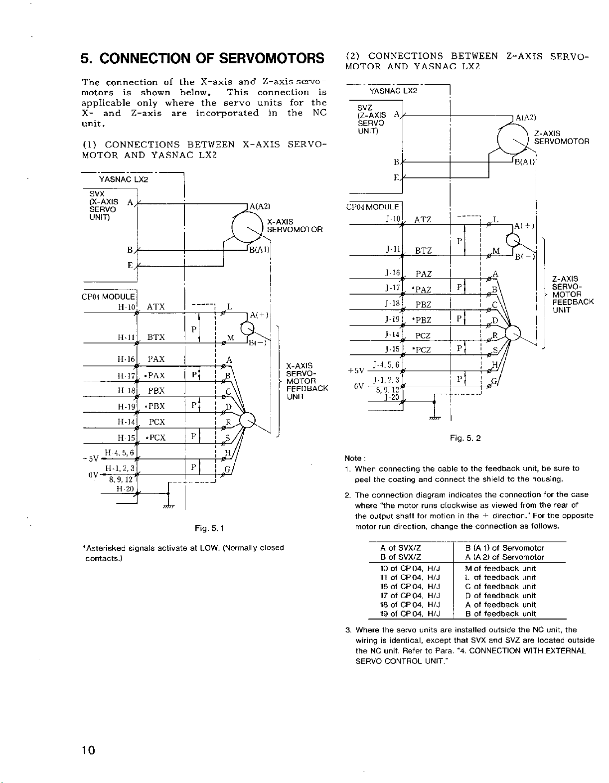
5.
CONNECTION
The
connection
shown
and
is
only
Z-axis
motors
applicable
X-
unit.
(1)
CONNECTIONS
MOTOR
AND
YASNAC
the
of
below.
where
are
OF
SERVOMOTORS
X-axis
the
servo
incorporated
BETWEEN
LX2
This
and
X-AXIS
Z-axis
connection
units
for
the
in
SERVO¬
servo¬
the
NC
(2)
CONNECTIONS
MOTOR
is
YASNAC
svz
(Z-AXIS
SERVO
UNIT)
AND
A,
YASNAC
LX2
BETWEEN
LX2
i
Z-AXIS
A(A2)
B(AI)
SERVO¬
Z-AXIS
SERVOMOTOR
SVX
(X-AXIS
SERVO
UNIT)
CP04
+
5V
OV
YASNAC
MODULE
H-
H
H-16
H
H-
H-19
H-14
H-15
H-4,
5,6
H-1,2,3
8,
12
9,
H
A.*-
10
-ll
17
18
20
LX2
if
0
0
0
if
if
if
if
if
if
0
ATX
BTX
PAX
PAX
•
PBX
PBX
•
PCX
•PCX
Tftrr
P
P
P
P
P
Fig.
;
5.1
-2-
A(A2)
X-AXIS
SERVOMOTOR
B(A1)
L
0
M
A
0
B
0
C
0
D
0
R
0
S
0
H
0
G
0
A(
B(-)
)
+
X-AXIS
SERVO-
MOTOR
>
FEEDBACK
UNIT
CP04
5V
+
0V
Note
1.
When
peel
The
2.
where
the
motor
MODULE
J
J-li
J-I6
J-17
-
J
J-
J-14
J-
J-4.5,6
J-1,2.3
9,
8,
-20
J
:
connecting
coating
the
connection
"the
output
run
10
if
if
*PAZ
if
18
if
19
*PBZ
if
0
15
*PCZ
0
0
if
12
0
motor
shaft
direction,
ATZ
BTZ
PAZ
PBZ
PCZ
T777T
Fig.
the
cabletothe
connect
and
diagram
for
indicates
runs
clockwise
motioninthe+direction.
change
P
P
P
3
P
the
*-
0
0
0
0
0
0
0
0
0
5.
2
feedback
shield
the
the
as
connection
L
;A(
M
A
B
C
D
R
s
H
G
to
connection
viewed
B(
the
+)
—
unit,
from
B
as
)|
>
be
housing.
for
the
the
For
follows.
Z-AXIS
SERVO-
MOTOR
FEEDBACK
UNIT
sure
to
the
case
rear
of
opposite
•Asterisked
contacts.)
10
signals
activate
at
LOW.
(Normally
closed
3.
Where
wiring
NC
the
SERVO
A
of
SVX/Z
of
SVX/Z
B
CP
Of
10
11
CP
of
16
of
CP
of
CP
17
18
of
CP
of
CP
19
servo
the
identical,
is
unit.
Refer
CONTROL
04,
04,
04,
04,
04,
04,
H/J
H/J
H/J
H/J
H/J
H/J
units
except
to
UNIT."
are
Para.
(A1)
B
2)
(A
A
M
feedback
of
of
feedback
L
Coffeedback
of
feedback
D
of
feedback
A
of
feedback
B
installed
that
SVX
"4.
CONNECTION
Servomotor
of
of
Servomotor
outside
SVZ
and
unit
unit
unit
unit
unit
unit
the
are
WITH
unit,
NC
located
EXTERNAL
the
outside
Page 17
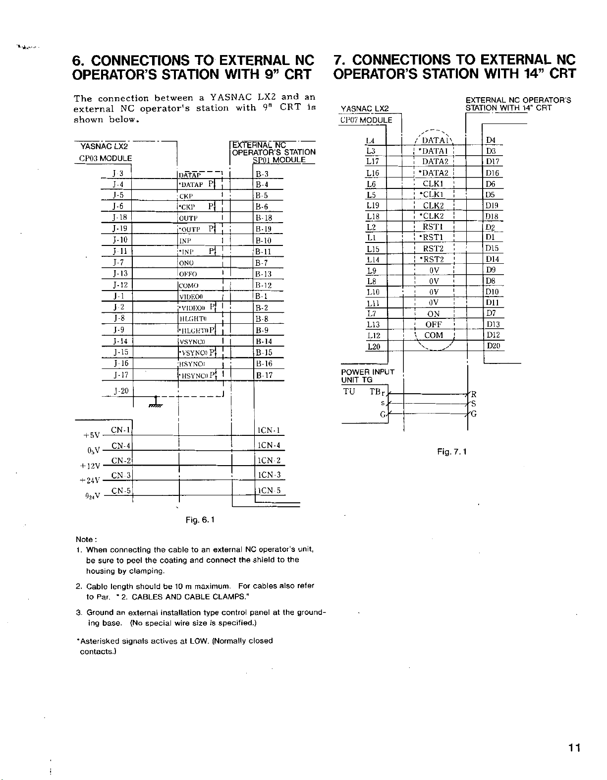
6.
CONNECTIONS
OPERATOR’S
connection
The
external
shown
NC
below.
between
operator's
TO
STATION
YASNAC
a
station
EXTERNAL
with
9”
LX2
9"
CRT
and
CRT
WITH
NC
an
7.
CONNECTIONS
OPERATOR’S
is
YASNAC
Cl’07
MODULE
LX2
TO
STATION
EXTERNAL
STATION
EXTERNAL
NC
WITH
14”
OPERATOR
CRT
14"
WITH
NC
CRT
S
YASNAC
MODULE
CP03
LX2
3
J
J-4
J-5
J-6
J-18
19
J-
J-10
a
J
J-7
13
J-
12
J-
J-l
2
J
J-8
.1-9
14
-
J
J-15
16
J
17
J-
-
20
J
DATAP
P|
•DATAP
CKP
P
•CKP
OUTP
P|
•OUTP
1NP
ONO
OKFO
COMO
VIDKOtl
•VIDEOll
IILGHTO
wr
P
.•INI’
•ULGHTnP
VSYNCO
P
HSYNCO
•HSYNCO
P
EXTERNAL
OPERATOR'S
SPfll
B-3
B-4
B
B-6
B-
B-19
B-10
BB-7
B-
B-12
B
B-2
B-8
B-9
B-
B-15
J
5
18
11
13
1
14
B-16
17
B-
NC
STATION
MODULE
L4
_
L3
L17
L16
L6
L5
L19
L18
1,2
LI
L15
L14
L9
L8
L10
Lll
L7
LI
3
L12
L20
TU
TG
INPUT
TB
POWER
UNIT
/DATAI\
'DATA1
DATA
•DATA2
CLK1
*CLK1
CLK2
*CLK2
RST1
•RST1
RST2
•RST2
OV
OV
OV
OV
ON
OFF
+
COM
-v
*
2
D4
D3
D17
D16
D6
D5
D19
D18
D2
D1
D15
D14
D9
D8
DIO
Dll
D7
D13
D12
D20
5V
+
o,v
12V
+
24V
+
02<V
Note
:
connecting
When
1.
be
sure
housing
Cable
2.
Par.
to
3.
Ground
ing
base.
•Asterisked
contacts.)
CN-1
CN-4
CN-2
CN
CN-5
to
by
length
"
2.
an
signals
3
peel
the
clamping.
should
CABLES
external
special
(No
the
cable
coating
be
AND
installation
actives
10
wire
at
Fig.
an
to
and
maximum.
m
CABLE
size
LOW.
1
6.
external
connect
CLAMPS."
control
type
specified.)
is
(Normally
the
For
1CN-1
1CN-4
1CN-2
1CN-3
1CN
NC
shield
cables
panel
closed
5
operator's
to
also
the
at
unit,
the
refer
ground¬
Fig.
7.1
11
Page 18
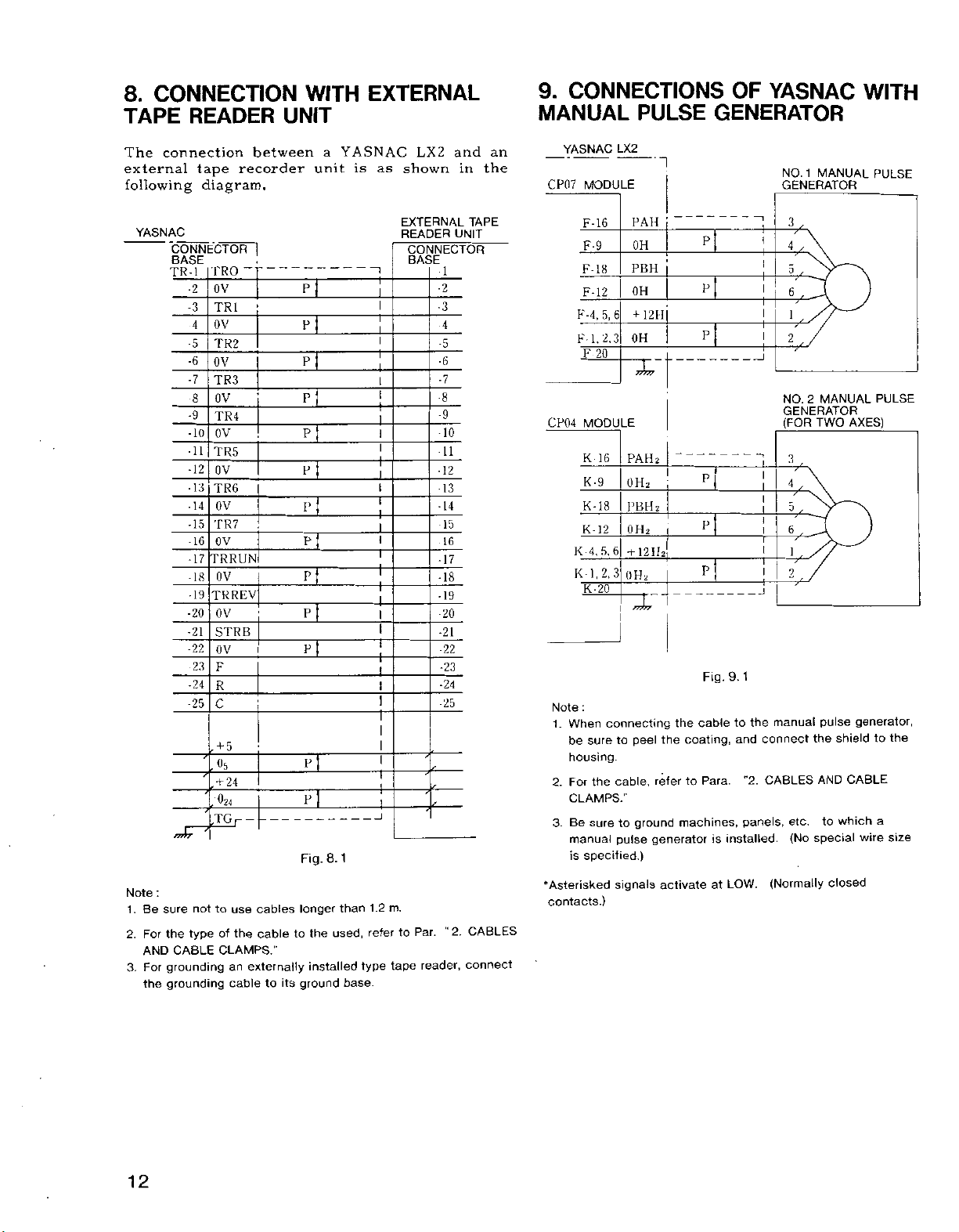
8.
CONNECTION
TAPE
READER
WITH
UNIT
EXTERNAL
9.
CONNECTIONS
MANUAL
PULSE
OF
YASNAC
GENERATOR
WITH
The
connection
external
following
YASNAC
Note
:
sure
Be
1.
the
For
2.
AND
grounding
For
3.
grounding
the
YASNAC
tape
between
recorder
unit
a
is
as
diagram.
PRO
ov
TRI
OV
TR2
OV
TR3
OV
TR4
ov
TR5
OV
TR6
OV
TR7
OV
TRRUN
OV
TRREV
0V
STRB
ov
F
R
C
5
+
I
~T
EL
n
EL
P
n
El
p
PT
n
u
EE
CONNECTOR
BASE
TR-I
I
2
3
4
5
6
7
8
9
10
11
12
13 13
14
15
16 16
17
18
19
20
21
22
23
24
25
,
El
24
,
J7nr
not
type
CABLE
+
,'0?4
-TGr
use
to
the
of
CLAMPS."
externally
an
cabletoits
cables
cable
p
Fig.
longer
the
to
installed
ground
8.
used,
1
than
base.
1.2
refer
type
m.
tape
and
LX2
Par.
reader,
1
2
3
4
5
6
7
8
9
10
11
12
14
15
17
18
19
20
21
22
23
24
25
"
in
UNIT
2.
shown
EXTERNAL
READER
CONNECTOR
BASE
to
an
the
TAPE
CABLES
connect
YASNAC
MODULE
CP07
F-16
F-9
IK
F-
F-12
K-4,
FI.
20
F
CP04
MODULE
16
K
K-9
K-18
12
K-
4,5,6
K
1,2.3
K
K-20
:
Note
When
1.
sure
be
housing.
For
the
2.
CLAMPS."
Be
sure
3.
manual
specified.)
is
•Asterisked
contacts.)
LX2
PAH
OH
PBH
OH
5,
+
6
1
2.3
OH
PAH
OH2
PBH;
OH;
+
12H2j
OH;
~X
connecting
peel
to
cable,
ground
to
pulse
signals
II
2
|
2
i
1
the
the
refer
machines,
generator
activate
P
5
P
P
P
P
Fig.
cable
coating,
Para.
to
is
at
J
9.1
to
the
and
connect
"2.
CABLES
panels,
installed.
LOW.
1
NO.
MANUAL
GENERATOR
I
5
6ÿ
l
2
MANUAL
NO.
2
GENERATOR
(FOR
TWO
3
4ÿ
D
6
1
2
pulse
manual
the
AND
to
etc.
(No
special
(Normally
AXES)
shield
CABLE
which
closed
PULSE
PULSE
generator,
the
to
a
wire
size
12
Page 19
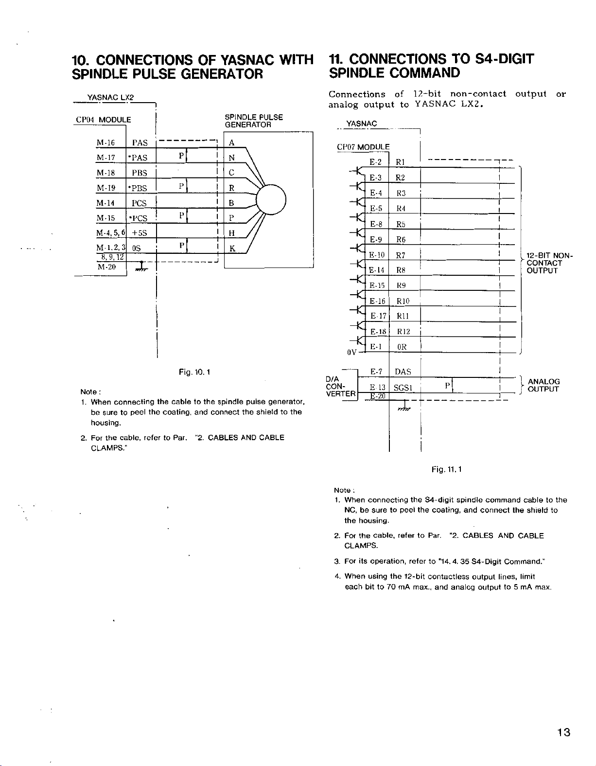
CONNECTIONS
10.
SPINDLE
PULSE
YASNAC
OF
GENERATOR
WITH
11.
CONNECTIONS
SPINDLE
COMMAND
TO
S4-DIGIT
YASNAC
CP04
Note
When
1.
be
housing.
For
2.
CLAMPS."
MODULE
M-16
M-17
M-18
M-I9
M-14
M15
M-4,5,6
2,
M
l.
8,9,
12
M-20
:
connecting
sure
the
LX2
PAS
•PAS
PBS
•PBS
PCS
•PCS
+
3
peel
to
cable,
5S
OS
rwXr-
the
refer
the
cabletothe
coating,
Par
to
P
P
P
P
Fig.
10.
and
"2.
SPINDLE
GENERATOR
J
1
spindle
connect
CABLES
ANALOG
OUTPUT
or
NON-
l?.-bit
E-2
E-3
E-4
E-5
E-8
E-9
E-10
E-
E-15
E-16
E-17
E-18
E-l
E-7
E
E¥
14
13
of
to
R1
R2
R3
R4
R5
R6
R7
R8
R9
RIO
Rll
R12
OR
DAS
SCSI
YASNAC
Connections
analog
PULSE
A
YASNAC
CP07
output
MODULE
N
C
R
B
P
H
K
HC
HC
HC
HC
HC
HC
HC
HC
HC
HC
HC
OV
D/A
CON¬
pulse
the
AND
generator,
shield
CABLE
the
to
VERTER
non-contact
LX2.
P
output
12-BIT
”
CONTACT
OUTPUT
Note
When
1.
NC,
the
For
2.
CLAMPS.
3.
For
When
4.
each
:
be
housing.
the
its
bit
connecting
to
sure
cable,
operation,
using
the
to
70
peel
refer
12-bit
mA
the
the
to
refer
max.,
Fig.
11.1
S4-digit
coating,
Par.
"2.
to
4.
"14.
contactless
analog
and
spindle
and
CABLES
S4-Digit
35
command
connect
output
output
cable
the
CABLE
AND
Command.”
lines,
limit
5
to
mA
shield
max.
the
to
to
13
Page 20
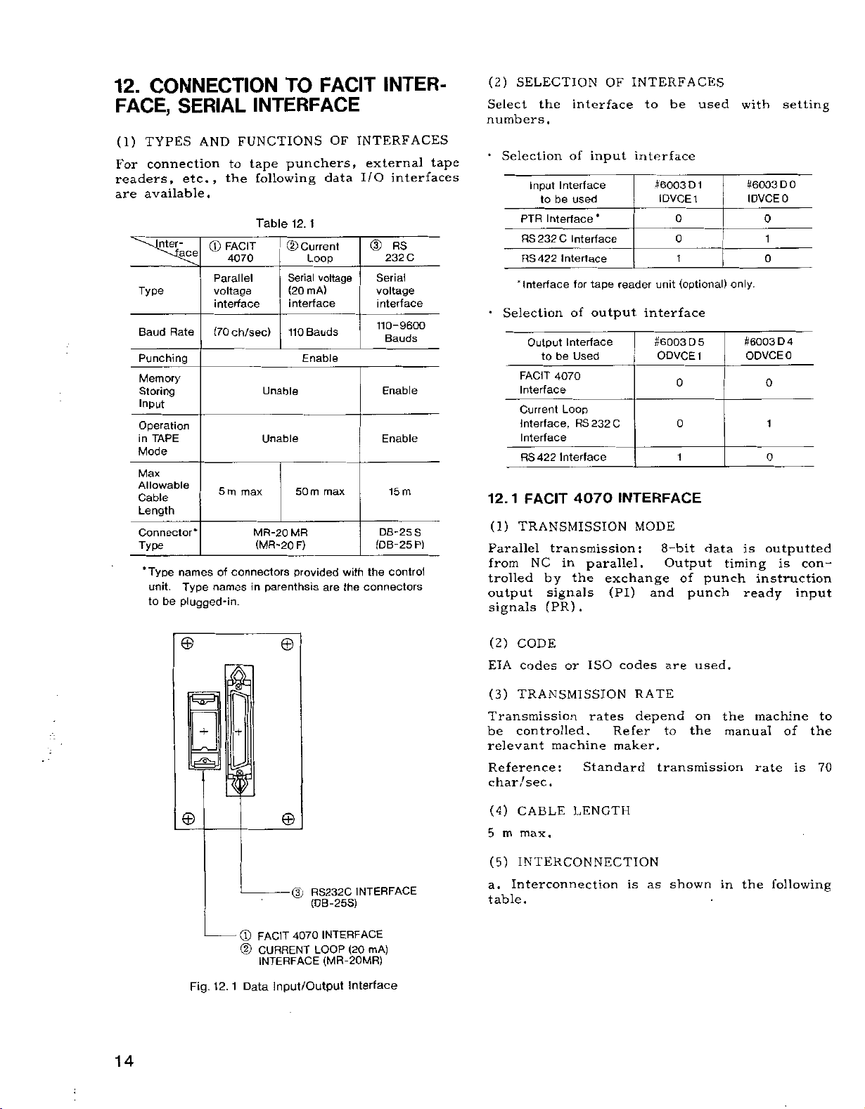
CONNECTION
12.
FACE,
(1)
For
readers,
are
SERIAL
TYPES
connection
available.
Inter-
[ace
Type
Rate
Baud
Punching
Memory
Storing
Input
Operation
in
TAPE
Mode
Max
Allowable
Cable
Length
Connector*
Type
‘Type
names
unit.
to
be
plugged-in.
AND
etc.,
Type
FUNCTIONS
to
the
FACIT
©
4070
Parallel
voltage
interface
(70ch/sec)
5
m
max
of
connectors
names
FACIT
TO
INTERFACE
OF
punchers,
tape
following
Table
Unable
Unable
MR-20
(MR-20
parenthsis
in
1
12.
Current
CD
Loop
Serial
mA)
(20
interface
Bauds
110
Enable
50
m
MR
F)
provided
data
voltage
max
are
with
the
INTER¬
INTERFACES
externa]
I/O
©
232
Serial
voltage
interface
110-9600
Bauds
Enable
Enable
15
DB-25S
(DB-25P)
the
connectors
tape
interfaces
RS
C
m
control
(2)
SELECTION
Select
numbers.
Selection
*
Input
PTR
RS232C
RS422
'Interface
•
Selection
Output
FACIT
Interface
Current
Interface,
Interface
RS422
12.
1
FACIT
(1)
TRANSMISSION
Parallel
NC
from
trolled
output
signals
the
interface
of
input
Interface
be
to
used
Interface
Interface
for
of
Interface
be
Used
4070
Loop
RS232C
Interface
*
tape
output
Interface
to
4070
transmission:
in
parallel.
the
by
signals
(PR).
OF
INTERFACES
to
interface
#6003
1DVCE1
unit
reader
interface
#6003
ODVCE
INTERFACE
MODE
8-bit
Output
exchange
(PI)
and
be
D
0
0
1
(optional)
D
0
0
1
of
punch
used
1
5
1
data
punch
with
#6003
IDVCEO
only.
#6003
ODVCEO
is
timing
ready
setting
0
D
0
1
0
4
D
0
1
0
outputted
is
con-
instruction
input
©
+
le®3J
©
Fig.
12.
ft
+
1
®
©
Data
©
©
(3)
4070
FACIT
CURRENT
INTERFACE
Input/Output
RS232C
(DB-25S)
INTERFACE
INTERFACE
(20
LOOP
(MR-20MR)
Interface
mA)
(2)
CODE
codes
EIA
(3)
TRANSMISSION
or
Transmission
be
controlled.
relevant
Reference
char
(4)
m
5
(5)
a.
machine
:
/sec.
CABLE
max.
INTERCONNECTION
Interconnection
table.
ISO
rates
Standard
LENGTH
codes
RATE
depend
Refer
maker.
is
are
used.
on
the
to
transmission
shown
as
the
manual
the
in
machine
of
rate
following
to
the
is
70
14
;
Page 21
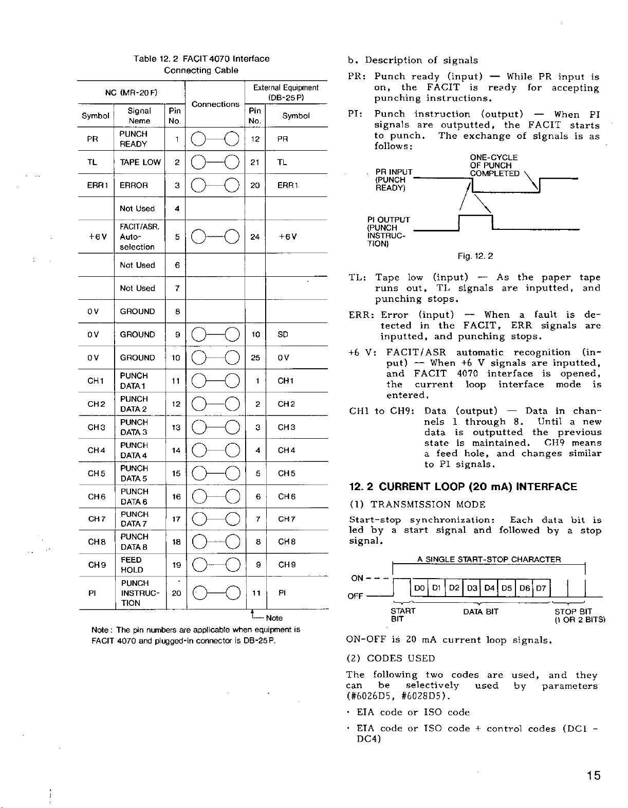
Symbol
PR
TL
ERR1
NC
Table
(MR-20
Signal
Neme
PUNCH
READY
TAPE
ERROR
F)
LOW
12.
2
FACIT4070
Connecting
Pin
No.
1
2
3
Interface
Cable
Connections
CH)
o-o
o—o
External
Pin
No.
12
21
20
Equipment
(DB-25P)
Symbol
PR
TL
ERR1
b.
Description
PR:
PI:
.
Punch
the
on,
punching
Punch
signals
to
punch.
follows
PR
INPUT
(PUNCH
READY)
of
ready
FACIT
instructions,
instruction
are
The
:
1
signals
(input)
is
outputted,
exchange
ONE-CYCLE
OF
COMPLETED
While
—
ready
(output)
the
PUNCH
of
PR
for
FACIT
signals
V
input
accepting
When
starts
is
is
PI
as
numbers
plugged-in
4
5
o-o
6
7
8
9
0-0
10
o—o
11
003
12
o—o
13
(H)
14
(K)
15
COO
16
0-0
17
oo
18
o—o
19
o—o
20
o—o
applicable
are
connector
when
is
24
10
25
1
2
3
4
5
6
7
8
9
11
Note
equipment
DB-25P.
+
SD
OV
CH
CH3
CH4
CH5
CH6
CH
CH8
CH9
PI
Not
Used
FACIT/ASR.
Auto¬
6
V
+
selection
Not
Used
Not
Used
2
3
5
PI
Note
FACIT
7
:
GROUND
GROUND
GROUND
PUNCH
DATA1
PUNCH
DATA
2
PUNCH
3
DATA
PUNCH
4
DATA
PUNCH
5
DATA
PUNCH
DATA
6
PUNCH
7
DATA
PUNCH
8
DATA
FEED
HOLD
PUNCH
INSTRUC¬
TION
The
pin
and
4070
OV
OV
OV
CH1 CH1
CH
CH
CH4
CH
CH6
CH
CH8
CH9
PI
OUTPUT
(PUNCH
6
V
2
7
INSTRUC¬
TION)
TL:
Tape
runs
punching
ERR:
Error
tected
inputted,
+6
FACIT/ASR
V:
put)
and
entered
to
CHI
2
12.
CURRENT
(1)
TRANSMISSION
Start-stop
led
by
low
out,
(input)
in
—
FACIT
the
current
CH9:
synchronization:
start
a
(input)
stops,
and
When
.
Data
nels
data
state
a
to
LOOP
signal
TL
the
feed
PI
Fig.
punching
automatic
4070
(output)
1
is
is
signals.
MODE
12.
signals
When
FACIT,
V
+6
loop
through
outputted
maintained.
hole,
(20
and
1
2
As
are
ERR
stops.
recognition
signals
interface
interface
8.
and
mA)
Each
followed
the
paper
inputted,
fault
a
is
signals
are
inputted,
is
opened,
mode
Data
in
Until
the
previous
CH9
changes
similar
INTERFACE
data
a
by
tape
and
de¬
(in¬
chan-
new
a
means
bit
stop
are
is
is
signal.
A
SINGLE
ON
-
-
OFF
is
ON-OFF
(2)
CODES
The
following
can
be
(#6026D5,
•
•
EIA
EIA
DC4)
code
code
START
BIT
is
20
USED
selectively
#6028D5)
or
or
DO
mA
two
ISO
ISO
D1
D2
current
codes
.
code
code
START-STOP
D4
D3
DATA
D5
BIT
loop
are
used
control
+
CHARACTER
D6
D7
signals.
used,
by
and
parameters
codes
STOP
(1
OR
(DC1
BIT
BITS)
2
they
-
15
;
i
Page 22

2
12.
CURRENT
(Cont'd
To
trolled
DC1
shown
(3)
The
a
(4)
The
with
the
)
control
use
must
through
below.
Character
Tape
DC1
start
Tape
2
DC
designation
Tape
3
DC
stop
_
Tape
DC
4
release
TRANSMISSION
transmission
parameter.
CABLE
LENGTH
permissible
machine
the
manual
of
Reference:
(5)
INTERCONNECTION
•
The
interconnection
Table
(MR-20
NC
V
2
1
Signal
Name
Not
FACIT/
ASR.
selection
Current
loop
Current
loop
GROUND
Not
type
of
equipment.
Symbol
6
+
TTY
TTY
0V
'The
external
LOOP
codes,
be
DC4.
reader
punch
reader
punch
Baud
Refer
maximum
the
Standard
12.4
Current
Connection
F)
Used
Auto¬
(-)
(+)
Used
connector
mA)
able
Table
8
DC1
7
(20
the
to
12.
6
INTERFACE
machine
discriminate
DC4
3
4
5
o
o
o
BAUD
to
to
machine
Pin Pin
No
1
s
4
5
6
7
8
9
20
and
o
o
RATE
rate
(6)
below.
cable
controlled.
be
maker.
max.
is
as
(20
Loop
Cable
Connections
0-0
o-o
pin
number
set
is
cable
shown
mA)
are
to
codes
Feed
Hole
at
length
length
below.
Interface
Equipment*
No.
different
be
codes
are
2
3
o
o
o
HOB
Refer
=
External
Symbol
with
con¬
as
1
o
o
with
varies
50
to
m
NC
The
to
DC4
machine
the
NC.
(6)
PARAMETER
When
the
length
with
•
Baud
Input
Output
VI
CD
—
>
<D
a
CD
using
data
and
the
100
110
150
200
300
600
1200
2400
4800
9600
Setting
#6026
D4
bits.
#6028
D4
bit.
•
Setting
#6026
D5
code.
#6028
12.
(1)
D5
3
RS232C
TRANSMISSION
Start-stop
preceded
signal.
stop
-
-
ON
OFF
START
BIT
FUNCTION
SIGNAL
CONDITION
LOGIC
outputs
start
can
and
not
current
transmission
the
control
following
rate
setting
#602603
#6028
of
of
for
for
for
for
0
0
0
0
0
0
0
0
1
1
1
step
input
output
control
input
output
50
INTERFACE
synchronization:
start
a
by
A
SINGLE
DO
D1
control
stop
output
SETTING
loops
parameters.
—
Table
#6026
D
3
#6028
bit
length
1:
0:
code
1:
0:
MODE
signal,
START-STOP
D3
D2
DATA
Table
V0<
OFF
MARK
control
Baud
code
Setting
5
12.
D
2
2
D
0
0
0
0
1
1
1
0
0
0
Sets
Sets
sending
Does
Sends
D4
BIT
6
12.
—
V
3
1
codes
machine.
the
codes
(and
rate
output
of
#6026
#6028
0
0
1
1
0
0
1
1
0
0
1
stop
stop
not
control
Each
and
CHARACTER
D5
D6
VO
DC1
to
RS232C),
9
designation
Bauds
110
D1
#6026
#6028
D1
bit
bit
send
data
followed
D7
STOP
(1
+3
>
ON
SPACE
0
through
control
stop
D
DO
0
1
0
1
0
1
0
11
0
1
0
at
at
control
code.
bit
by
BIT
2
OR
V
The
set
bit
0
two
one
is
a
BITS)
16
Page 23

(2)
CODES
The
following
and
(#6026D5,
•
•
EIA
EIA
(DC1
To
trolled
DC1
are
codes
codes
-
use
through
follows.
Character
Tape
DC1
start
Tape
DC
2
punching
Tape
3
DC
stop
Tape
4
DC
release
(3)
TRANSMISSION
Transmission
rate
any
parameters.
(4)
CABLE
The
permissible
the
with
the
manual
(Standard
USED
selectively
#6028D5)
or
or
DC4)
control
must
reader
reader
reader
_
punch
Baud
between
Refer
LENGTH
machine
of
maximum
two
.
ISO
ISO
codes,
be
DC4.
maximum
the
types
codes
codes
able
Table
7
8
o
BAUD
rates
50
to
be
to
machine
cable
used
the
to
Codes
12.
6
and
(7)
controlled.
length
of
codes
control
+
machine
discriminate
DC1
7
4
5
o
o
o
o
RATE
can
9600
below.
cable
builder's'
by
Feed
Hole
be
is
are
parameters
codes
to
DC4
3
o
selected
Bauds
length
15
used,
be
codes
are
2
o
o
varies
Refer
manual.
m.)
con¬
1
o
o
with
as
at
NC
outputs
and
stop
output
ever,
able
CS
when
to
signals
putting
When
short
to
CS
Symbol
FG
SD
RD
RS
CS
SG
the
control
process
of
the
CS
and
Table
(DB-25P)
NC
Signal
Name
Frame
grounding
Sending
data
Receiving
data
Sending
data
Capable
sending
Not
Signal
grounding
Not
used
control
machine,
codes
the
data
the
of
NC.
signals
RS
9
12.
of
used
codes
machine
in
NC
shown
as
RS232C
Cable
Pin
No.
1
2
3
4
5
6
7
8
25
DC1
but
the
to
control
under
time,
halt
to
of
the
NC
Table
Interface
(B)
Connections
—
o
CHHD
O
HD
-
machine
the
control
can
it
the
are
12.9.
Connecting
o
O
o
DC4
NC.
control
data
not
External
Equipment
Pin
No.
ER
IO
to
can
How-
is
used,
Symbol
FG
SD
RD
RS
CS
DR
SG
(OR
ALARM)
start
not
un¬
the
out-
(5)
INTERCONNECTION
12.
Signal
Name
used
RS232C
8
of
Cable
Connections
Pin
No.
1
o—o
2
3
4
5
6
7
O
8
+
25
Interface
(A)
Table
(DB-25P)
NC
Symbol Symbol
Frame
FG FG
grounding
Sending
SD
data
Receiving
RD
data
Sending
RS
data
Capable
CS
sending
Not
Signal
SG
grounding
Not
used
Connecting
O
rO
O
HD
External
Equipment
Pin
No.
SD
RD
RS
CS
DR
SG
10
ER
BUSY
b.
Description
FG:
SD:
RD:
RS:
CS:
SG:
ER:
Safety
grounding
Transmission
Received
m
START
—
Request
NC
sends
starting
when
transmission
For
sending
signal
machine
process
signal
data
this
shown
Signal
Data
is
data
to
from
signal
in
grounding.
terminal
of
signals
data
(input)
data
i
i i
i i i i
for
sending
data,
transmission,
(input)
NC
on,
under
in
time,
interrupt
NC
within
is
not
Table
12.9.
ready
(output)
is
it
ends.
—
can
control
the
2
used,
—
V.
STOP
(output)
turned
and
When
send
data.
is
can
it
transmission
characters.
connect
Not
used
turned
unable
turn
on
this
off
lines
by
When
when
input
If
When
NC.
off
the
to
this
of
as
17
Page 24

12.
(6)
•
i.
ii.
iii
iv.
v.
vi.
vii.
viii.
RS232C
3
Among
the
the
DR:
ER:
CD:
However,
eter
set
SIGNAL
When
Data
quence
NC
At
starts
If
.
sends
At
data
NC
data.
At
data
one.
Upon
code
The
RS
OUTPUT
SD
OUTPUT
RD
INPUT
CS
INPUT
following
NC.
Data
Data
Data
CHKDR
ready)
NC
receives
can
and
sends
code
to
the
out
code
within
again
code
that
reading
DC3.
machine
INTERFACE
RS232C
the
are
set
ready
terminal
receiving
when
(#6021
interlock
EXCHANGE
be
received
timing.
code
DC1,
send
NC
can
not
code
DC3,
10
characters.
sends
DC1,
succeeds
in
stops
DC1
n
_
\
NOTE
normally
"1"
data.
DC1.
the
data
DC3.
the
code
the
the
DC3
n
|\
Fig.
(Cont’d)
interface
ready
carrier
is
D4)
is
added.
TIMING
in
machine
to
NC.
process
machine
DC1
machine
the
data,
sending
DC
I
n
\
10
3
12.
signals,
used
not
detection
for
DR
a
following
param¬
set
,
the
under
data
in
stops
processing
after
sends
previously
NC
sends
data.
DC3.
n
\
/
(ER)
CHARACTERS
(data
control
time,
sending
out
1
MAX
by
se¬
the
sent
out
of
H
I
12.
rates,
12.
0
0
0
0
1
1
1
1
0
0
0
1:
4
02
D
data
sending,
J
CHAR-/
ACTERS
-
MAX
current
bit
stop
specifications
10
#6026D1#6026
#6028D1#6028
2
0
0
1
1
0
0
1
1 1
0
0
1
Sets
stop
DC4
loop)
}
lengths,
0
1
0
1
0
1
0
0
1
0
bit
NC
,
set
with
D
0
DO
two
at
rate
50
100
110
150
200
300
600
1200
2400
4800
9600
bit
D4
completion
code
out
DC2
SETTING
RS232C
code
shown
setting
#6026
#6028
0
0
0
0
0
0
0
0
1
1
1
length
for
input
Fig.
Baud
sending
Table
D
3
3
D
setting
DC4.
(and
below.
#6026
#6028
Upon
iv.
sends
RS
OUTPUT
SD
OUTPUT
CS
INPUT
(7)
PARAMETER
When
data
and
the
•
it
transmission
parameters
Baud
i/>
3
>
o
"D
CO
m
•
Stop
using
control
Input
Output
#6026
bits.
#6028
D4
for
output
stop
bit
Sets
0:
one
at
bit.
•
Setting
#6026
D5
of
control
for
input
code
1:
sending
Does
not
send
control
code.
#6028
D5
for
output
Sends
0:
control
code.
•
i.
ii.
iii.
18
When
NC
and
If
sends
timing.
NC
tly
cess
IO
Upon
the
out
NC
sends
sends
sends
machine
the
the
BUSY
completion
machine,
data
out
data
out
out
data
signal.
that
out
data
in
code
data.
under
time,
in
of
turns
NC
succeeds
the
DC2,
the
following
control
NC
data
on
the
subsequen¬
and
can
stops
processing
CS.
previous
sequence
pro¬
not
at
CS
sends
NC
one.
no
by
Page 25

13.
CONNECTION
INPUT
UNITS
WITH
POWER
1
13.
LIST
Signal
DS
DS2
The
terminals
with
•
r,
For
NECTIONS
rl,
integrated
are
additional
OF
Symbol
P01
PQ2
S01
2
SO
DSA
1
DSD
EL
1
2
EL
ES
1
ES2
EON
EOF
ECM
1
OL
OL2
switching
r,
the
respective
s,
G:
their
si,
wired
CONNECTION
Table
Signal
power
NC
output
power
Servo
output
switch
Door
output
Machine
Emergency
input
External
ON/OFF
Overload
units
in
G,
s,
functions
Control
connection,
OF
r2,
power
at
wiring
s2,
POWER
r3,
the
input
supply
factory,
aÿe
SIGNALS
1
13.
Name
on
on
input
end
stop
power
input
input
are
addition
power
refer
SUPPLY."
s3:
strictly
as
Wiring
units
and
VAC,
230
50VDC
mA
500
MAX
30V
mA
100
Ratings
MAX
MAX
MAX
Contact
provided
the
to
shown
below.
terminals.
to
4.
"
terminals
NC.
for
reconnection
be
to
avoided.
with
above,
CON-
They
for
and
SWITCH
DOOR
INTERLOCK
SWITCH
KEY
YASNAC
TU
(POWER
INPUT
Cl
f-O
O
p=£-
1DRS
I.'V.
Q
-
t_a
C\J-ON-
OV
UNIT)
mi
1*02
SOI
S02
I>S1
SI
D
DSA
TB
DSA
USB
TB
-
USB
USC
IB
use
USD
TB
USB
EL2
ELI
ESI
ES2
LON
EOF
EtM
Fig.
13.
1
CONTROL
SERVO
TROL
CON
R
SW
DOO
DS1,
DS2
DSA-DSD
/DS1.
\
DSA-
t9-e=9-i
POWER
ON
ON
POWER
CABINET
OUTPUT
ITCH
DS2
\
DSD/
STROKE
LS
END
EMERGENCY
-oSS-j
STOP
—
I
H
EXTERNAL
POWER
.
,
ON/OFF
2
DETAILS
13.
1
13.'2.
ON
(1)
the
(2)
the
servo
this
(3)
as
a.
NC
1-2)
(SO
PO
1-2:
logic
SO
1-2:
servo
unit,
signal
The
follows.
Close
control.
Either
b.
NC
operator’s
between
circuit
both
POl
closed.
is
With
the
sequence
gized
nals
;
OF
POWER
circuit
unit
turn
is
outputted.
power
the
power
push
EON
and
energized,
P02
and
an
servo
at
.
SIGNALS
(PO
ON
This
output
the
of
This
is
energized.
on
supply
supply
the
station,
and
the
(NC
external
control
that
so
the
output
1-2)
control
output
the
turning
POWER
ECM.
servo
and
power
servo
circuit
the
AND
is
is
power
main
ON
or
control
the
input
circuit
POl
of
SERVO
turned
is
energized.
turned
With
supply
on
switch
button
close
Then,
circuit
unit,
power
and
POWER
when
off
when
off
external
an
when
sequence
for
on
the
circuit
the
circuit
between
output)
and
design
input
ener¬
is
2
sig¬
the
the
logic
are
ECM).
unit,
power
1
and
is
and
is
switching
or
S02
is
ready
SO
displayed
closing
Now,
on,
(servo
design
input
ener¬
2
sig¬
after
2
ready,
input
becomes
and
is
of
the
POWER
supply
output)
that
output
the
(machine
Then,
and
same
EON
control
c.
Again
(pushing
the
the
the
power
is
d.
When
the
closed,
close
the
on
make
circuit
servo
circuit
input
an
With
servo
the
sequence
at
gized
nals.
the
circuit
the
I/O
the
the
between
power
between
and
external
power
so
the
external
between
and
MRD
module.
CRT,
ON
SOI
servo
circuit
the
of
circuit
SO
power
button
and
is
turned
and
closed.
is
circuit
SO
1
becomes
ready)
RDY
operation
possible.
19
Page 26

13.
2.
1
(SO
ON
POWER
PB
POl
(OUTPUT)
SOI,
2
(OUTPUT)
MRO
(INPUT)
Fig.
13.
2.
2
13.
(1)
DS1-2
attached
Door
unit
circuit
door
is
NC
1-2)
ON
2
Time
DOOR
switch
door
between
open.
POWER
CRT
PLAY
Chart
SWITCH
Output
type
output
is
SCREEN
2)
open.
DS1
(PO
ON
DIS-
COOE
ALARM
Power
of
(DS
(Free-standing
indicates
and
1-2)
CRT
PLAY
•280-
Supply
1-2)
With
2
SERVO
AND
CIS-
SCREEN
ALARM
CODE
Turning
OUTPUT
that
this
closed,
is
POWER
CRT
DISPI
DISPLAY
On
type
the
output,
while
SCREEN
-RD
LAY
Y
Sequence
and
control
the
the
4
13.
2.
INPUT
The
control
external
pushing
NC
operator's
tween
servo
or
When
opened,
control
EOF.
EON.
CONTROL
CIRCUIT
SUPPLY
CONTROL
POWER
5
13.
2.
EXTERNAL
can
input
of
EON
signals,
the
and
power
circuit
the
the
logic
is
deenergized.
CLOSED
ECM
OPEN
CLSED
ECM
OPEN
LOGIC
POWER
SERVO
SUPPLY
OVERLOAD
POWER
be
POWER
station.
ECM
of
between
circuit
Fig.
(OL1
ON-OFF
switched
in
ON/OFF
closed,
is
the
or
13.
3
AND
the
When
control
EOF
servo
2)
INPUT
(EON,
on
same
buttons
the
the
is
EOF,
and
way
circuit
logic
energized,
and
power
u~
ECM)
off
as
on
circuit
ECM
of
by
the
the
be-
is
the
(2)
DSA-D
bundle
This
output
open.
•
With
and
while
signals
can
ineffective
is
open.
•
With
and
while
signals
can
ineffective
is
open.
3
13.2.
(EL
END
When
terminals
machine
open,
power
stop
module
Output
type)
indicates
this
output,
DSC
or
between
the
door
used,
are
be
kept
open
switch
this
output,
DSC
or
between
the
door
used,
are
be
kept
open
switch
EMERGENCY
1-2)
INPUT
the
circuit
ESI
end
input
the
control
supply
output
is
is
(*ESPS)
opened.
is
is
STOP
between
and
turned
(Attached
the
the
DSA
open.
the
means
by
(KEY
the
DSB
open.
the
means
by
(KEY
(ES
ES2
terminals
stops
off,
of
type
control
circuit
and
When
circuit
of
SW)
even
circuit
and
DSD
When
circuit
of
SW)
even
1-2)
AND
emergency
is
open
ELI
totally,
and
general
unit
between
DSD
DSA
between
door
while
between
is
DSB
between
door
while
MACHINE
stop
or
and
the
the
emergency
purpose
and
door
DSA
is
open,
DSC
and
them
interlock
door
DSB
closed,
DSC
and
them
interlock
door
input
between
EL2
servo
un¬
I/O
is
is
They
tion
terminals
DCP-
connect
(Power
When
opened,
power
power
state.
are
them
input
OL1
OL2
the
the
supply,
I/O
(Alarm
for
A)
SOI
.
-
-
circuit
connecting
of
the
With
as
follows.
unit)
-
-
between
control
opens
and
code
to
an
the
power
external
servo
(Servo
JUSP-DCP-C1
JUSP-DCP-C3
turns
the
S02,
357
off
circuit
and
is
displayed.)
overload
power
OL1
enters
unit
servo
unit)
and
the
between
servo
an
detec¬
(JUSP-
unit.
OL2
servo
alarm
is
unit
20
Page 27

14.
CONNECTION
PURPOSE
RATING
14.
1
(1)
30
ms
(2)
ing
•
As
20
V,
max.
Use
conditions.
50
max.
V
mA
500
VA
5
the
the
max.
max.
input
mA
MODULE
I/O
OF
CONTACTS
contacts,
above,
or
output
TO
and
contacts
All
satisfied.
GENERAL
ones
use
chattering
a
under
conditions
the
must
(AND)
rated
for
of
follow¬
be
5
Where
*
sure
within
•
Where
sure
total
within
Where
connect
total
within
14.
2
LIST
{EXCEPT
an
to
20
a
to
current
the
a
current
the
FOR
inductive
connect
the
of
cm
capacitive
connect
a
including
conditions
load
lamp
a
preheating
including
conditions
CONNECTION
OF
UNBUNDLED
a
load.
series
is
load
spark
load
resistor
given
connected,
resistor
given
TYPE)
connected,
is
killer
is
connected,
to
the
rush
mark
in
+
be
to
the
rush
in
mark
t
SIGNALS
in
parallel
limit
current
left.
sure
limit
current
left.
be
be
the
to
the
No.
02-9
02-16
06-3
02-2
02-8
02-15
02-3
01-7
01-20
01-5
01-11
to
I/O
connection
(Example)
less
Signal
start
hold
start
mode
input
input
input
output
operation
traverse
current
Name
input
input
output
stop
mode
input
input
input
data
input
operation
operation
input
Table
Module
I/O
Connector
No.
Pin
1001-1.
02-19
02-7
1001-1.
IOOM.12-2
12-8
01-1.
IO
1001-1.01-8
01-15
IO
01-1.
01-9
01-1.
IO
1001-1.
01-16
01-4
10
01-1.
1001-1.01-10
01-1.10-6
IO
01-1.10-12
IO
1001-1.10-7
1001-1.
01-2
mA
or
Cycle
Feed
Cycle
Temporary
output
(Operation
input/output)
Jog
Handle/step
Tape
Manual
operation
Memory
Edit
Automatic
mode
Manual
mode
Edit
output
Rapid
selection
200
and
24
V
.
Par.
No.
14.4.1
Symbol
ST
*SP
STL
SPL
14.4.2
JOG
H/S
T
MDI
MEM
EDT
AUT
MAN
EDTS
14.
RPD
3
4.
Listed
modules.
14.
2.
Par.
No.
14.
14.
14.
14.
below
1
Symbol
4
HX
4.
HZ
HOFS
5
4.
+
-X
+
-Z
4.6MP
MP2
MP4
4.
7
FV
FV2
FV
FV8
FV16J
0VC
X
Z
1
1
4
the
are
Signal
Manual
X-axis
Manual
Z-axis
Automatic
off-set
Manual
direction
input
Handle/step
multiplication
factor
Feedrate
manual
selection
Feedrate
cancel
Name
handle
input
handle
input
feed
selector
input
override/
jog
input
override
input
handle
axis
feedrate
signals
I/O
Module
Connector
Pin
10
01-1.
10
01-1.
1001-1.
1001-1.
1001-1.
10
01-1.
IO
01-1.
1001-1.
1001-1.01-13
1001-1.
1001-1.01-17
1001-1.
10
01-1.
1001-1.01-18
IO
01-1.01-6
10
01-1.06-2
'Asterisked
(Normally
signals
closed
activate
contacts.)
at
LOW.
21
Page 28

14.
2
LIST
14.
14.
14.
14.4.11
14.
14.
14.
14.
14.
14.
14.
14.
14.
14.
14.4.22
14.
14.4.24
14.
14,
Par.
No.
4.8
4.
4.
4.
4.
4.
4.
4.
4.17
4.18
4.
4.
4.
4.
4.
4.
CONNECTION
OF
Symbol
ROV
ROV
9
ZRN
*DCX
*DCZ
ZPX
ZPZ
2
ZPX
2
ZPZ
ABS
10
SBK
12
BDT
BDT
to
BDT
13
MLK
DLK
DRN
14
15
PST
16
PRST
INHEDT
AFL
SRN
19
OPRN
20
*
21
+LX
-
LX
*
*
+LZ
*
~LZ
MRD
‘ESPS
23
ERS
RST1.2
STLK
25
26
ALM
IER
ERRO
ERR1
1
2
2
9
Signal
Rapid
feedrate
override
Manual
point
Reference
return
input
Reference
output
Second
point
Manual
on/off
Single
Optional
skip
reference
return
deceleration
reference
output
absolute
input
block
input
Machine
Display
lock
input
Dry
run
Current
storing
Program
value
input
input
Edit
lock
Aux
function
input
point
up
Set
input
Restart
after
interruption
manual
Overtravel
input
Machine
input
Emergency
output
External
Reset
output
Interlock
output
Alarm
error
Input
External
detection
SIGNALS
Name
input
input
point
point
input
block
input
lock
input
restart
input
lock
return
ready
stop
input
reset
input
output
error
output
d)
(Cont
Table
Module
I/O
Connector
No.
Pin
01-1.
01-12
IO
10
01-19
01-1.
1001-1.03-3
03-13
IO
01-1.
01-1.03-20
IO
12-16
1001-1.
01-1.
IO
12-4
01-1.
12-10
IO
IO
01-1.12-17
10
01-1.
02-18
IO
02-4
01-1.
1001-1.
02-5
05-2,
1001-1.
8,
15,3,9,
4
16,
IO
01-1.
05-10
10
01-1.02-10
1001-1.02-17
1001-1.
02-11
01-1.02-13
IO
10
01-1.
06.-8
10
01-1.
02-12
10
02-6
01-1.
10
01-1.02-20
1001-1.
06-9
03-6
1001-1.
03-12
1001-1.
1001-1.03-19
1001-1.
03-7
03-9
10
01-1.
09-3
1001-1.
1001-1.03-4
IO
01-1.09-15
1001-1.03-5
09-2
IO
01-1.
10
09'
01-1.
03-11
1001-1.
1001-1.03-18
14.
4
2.
14.
14.
14.
14.
(Cont’d)
1
Par.
No.
14.4.27
14.
4.
14.
4.
4.
4.
4.
4.
28
29
30
31
32
33
Symbol
CDZ
SMZ
MIX
11
M
12
M
14
M
18
M
21
M
22
M
M
24
28
M
M
31
32
M
M34
M38
S11
S
12
14
S
S
18
S
21
S
22
S24
S28
1
1
T
12
T
14
T
18
T
T
21
T
22
24
T
28
T
MF
SF
TF
MOOR
M01R
M
R
02
M30R
FIN
1-2
DEN
OP
1-2
THC1-2
EOP
RWD
RWDS1-2
DRSX
DRSZ
Signal
Rapid
threading
pull-out
Error
input
X-axis
input
M
S
T
M,
reading
M
output
M,
completion
code
code
code
S,
code
S,
input
detect
mirror
output
output
output
code
T
output
decoded
function
T
Positioning
completion
on
Travel
Threadcutting
output
program
End
of
input
Rewind
Rewind
Display
input
input
output
reset
Name
on
image
input
output
I/O
Module
Connector
No.
Pin
1001-1.03-15
10
01-1.03-8
IO
01-1.06-15
1001-1.08-2
10
01-1.08-8
1001-1.
08-15
1001-1.08-3
1001-1.08-9
1001-1.08-16
1001-1.08-4
1001-1.08-10
10
01-1.08-5
10
01-1.08-11
10
01-1.
08-18
1001-1.08-6
1001-1.
11-2
11-8
1001-1.
1001-1.
11-15
1001-1.
11-3
10
01-1.
11-9
1001-1.
11-16
10
01-1.
11-4
1001-1.
11-10
1001-1.
11-5
1001-1.
11-11
1001-1.
11-18
10
01-1.
11-6
1001-1.
11-12
1001-1.
11-19
10
01-1.
11-7
11-13
1001-1.
1001-1.
10-8
1001-1.
10-15
10-3
1001-1.
10
01-1.08-12
1001-1.08-19
10
01-1.08-7
10
01-1.08-13
1001-1.03-16
1001-1.10-16
10-4
1001-1.
1001-1.
10-18
10
01-1.03-10
03-17
10
01-1.
IO
01-1.10-5
1001-1.04-12
1001-1.
04-19
22
Page 29

14.
14.
14.
14.
14.
14.
14.
Par.
No.
4.
4.
(Cont’d)
14.
9,
5,
12,
04-15,
4,
11,
19,
1
2.
Par.
No.
41
4.
14.
14.4.42
43
14.
4.
4.
14.
44
Symbol
WN1
WN
2
4
WN
8
WN
WN
16
EXTC
11
OF
OF
12
OF
14
OF
18
21
OF
OF
22
OF
24
OF
28
31
OF
32
OF
34
OF
38
OF
OFSN
DIX
DERR
DEND
XSTB
ZSTB
REND
SID
1
SID
2
3
SID
4
SID
SID5
SID
6
7
SID
8
SID
9
SID
SID10
SID11
SID
12.
SIDXiNC
SIDX
Signal
External
search
Time
(External
offset
work
input
count
input/
output)
Offset
changed
input
Offset
amount
input
sign
Offset
amount
input
sign
input
Data
error
Data
set
completion
X-axis
offset
output
set
offset
Z-axis
amount
Change
output
set
(Spindle
input/output)
Spindle
position
designation
Incremental
request
Index
Name
No.
input
tool
memory
amount
xio
input
input
amount
output
completion
index
index
input
input
input
Module
I/O
Connector
No.
Pin
1001-1.
05-18
1001-1.05-6
10
01-1.05-12
I0
01-1.
05-19
1001-1.05-7
10
01-1.
04-11
03-9
1001-2.
10
01-2.03-16
1001-2.03-4
10
01-2.03-10
I0
I0
10
1001-2.
03-17
01-2.
03-5
01-2.
01-2.03-11
03-18
1001-2.03-6
1001-2.03-12
1001-2.03-19
01-2.
03-7
IO
1001-2.03-13
10
03-20
01-2.
03-15
1001-2.
1001-2.03-3
IO
01-2.10-8
1001-2.10-15
1001-2.10-3
1001-2.01-2
1001-2.01-8
10
01-2.01-15
1001-2.01-3
1001-2.01-9
1001-2.01-16
1001-2.01-4
1001-2.01-10
10
01-2.01-17
10
01-2.01-5
1001-2.01-11
IO
01-2.
02-18
1001-2.02-2
01-13
1001-2.
Table
Module
I/O
Connector
No.
Pin
04-7
1001-1.
10
04-13
01-1.
1001-1.04-20
34
35
Symbol
EIN
EVER
EOUT
Signal
External
input
External
input
tion
External
input
(S
4-digit
Name
storing
collabora¬
output
command
input/output)
R01
to
R12
DAS
SGS1
GR1
GR2
GR3
GR4
SINV
SINVA
36
SSTP
4.
GRS
GSC
37
SAGR
4.
SPA
4.
38
SPB
SPC
4.
39
SMN
SAT
MNS
SG2
COMS
SGS1
40
4.
R01
to
R012
SDOO
to
4-digit
S
command
noncontact
output
4-digit
S
command
analog
Spindle
range
4-digit
S
output
S4-digit
output
Spindle
command
shift
Gear
indication
Spindle
speed
input
Spindle
input
Spindle
override
4-digit
S
output
manual
input/output
4-digit
S
external
12
output
gear
input
analog
analog
s
"0"
input
constant
speed
speed
input
analog
auto
selection
command
output
bits
input
reach
and
'
Refer
to
"12.
Par.
Connections
S4-digit
to
Spindle
Command”
10
01-1.04-15
01-1.04-3
10
04-9
1001-1.
01-1.04-16
IO
04-4
IO
01-1.
1001-1.10-2
10
04-10
01-1.
1001-1.
04-5
04-17
10
01-1.
04-8
01-1.
IO
05-17
1001-1.
10
01-1.05-5
01-1.05-11
IO
04-18
1001-1.
01-1.04-6
10
E-12
03.
CP
E-19
03.
CP
E-6
03.
CP
03.
CP
E-1
08-2,
1001-2.
3,
8,
15,
16,4,10,
18,
6,
11.
7,
19,
13
SD015
10
RI1
to
R012
SDI
to
SD1
0
15
4-digit
S
external
command
input
01-2.
9,
16,
3,
17,
10,
18,6,12,
20
13,
7,
5,
23
Page 30

14.
2
LIST
Par.
No.
4.
14.
(Cont’d)
4.
14.
14.
4.
14.
4.
14.
4.
44
45
46
47
48
CONNECTION
OF
Table
Symbol
SIDXI
SIDXA
SIDXO
TP
TP
TP
TP
TPS
TPSA
Restart
Index
output
Index
1
2
4
8
Tool
Area
completion
UIO
to
U1
15
uoo
to
U015
(External
input/output)
EDO
to
ED
15
EDSA
EDSB
EDSC
EDSD
EDASO
EDAS1
EDAS2
EDCL
EREND
ESEND
TLA
TLA
TLA
TLA
TLA
TLTM
TLSKP
TLRST
TLCH1-2
Data
External
input
output
External
search
(Tool
input/output)
11
12
14
18
21
Tool
time
Tool
Tool
completion
Tool
output
(Cont'd)
2.
1
14.
Signal
Name
input
completion
output
stroke
Stored
3
for
limit
tool
input
No.
change
macro
User
system
variables
input
system
User
variables
output
data
input
Data
Data
designation
designation
Axis
incremental/
absolute
designation
request
input
data
completion
data
completion
life
control
change
Tool
completion
input
No.
operation
input
skip
input
change
change
SIGNALS
each
output
input
group
input
request
(Cont’d)
I/O
Module
Connector
No.
Pin
02-8
I0
01-2.
IO
01-2.10-16
1001-2.10-5
1001-2.01-6
1001-2.01-12
10
01-2.01-19
IO
01-2.01-7
01-2.
IO
IO
10
1001-2.
8,
16,
12,
10
15,
10,
12, 19,
16,
12,
01-2.10-4,
15,
4,
11,
5,
19,
01-2.11-2,
3,
5,
10
01-2.
15,
8,
4,
5,
11,
19,-7
01-2.07-2
IO
01-2.07-8
IO
3,
10,
18,
9,
11,
3,
10.
18,
01-20
05-2,
9,
17,
6,
7
16,
18,
13
7.
06-2,
9,
17,
6,
1001-2.07-15
01-2.07-3
IO
10
01-2.
07-9
1001-2.
07-16
1001-2.
07-4
01-2.07-10
IO
10
01-2.10-7
1001-2.10-13
1001-2.02-4
1001-2.
IO
1001-2.
1001-2.
1001-2.
IO
IO
10
19
02-10
01-2.02-17
02-5
02-11
02-16
01-2.02-3
01-2.02-15
10-18,
01-2.
(Cont'd)
Table
Par.
No.
14.
14.
14.
14.
14.
3
14.
(EXCEPT
8,
6,
The
diagrams
type
YASNAC
1
IOOl
+
V
24
RT
[ÿjpc,
810001
H/S
I—
10002
O
810003
QI
-
'810005
.—.MEM
8
0006
1
—
'
’
[-}EDT_
lj#10007
QIXL_
'—'*10010
FV2
LJ1
8iooit
FV4
FVS
O’
*10013
FVK
ROV1
D
*10015
.ROV2
j—
1
010016
—
'
MPl
MP2
l—hn0020
MP4
D"
s
10021
ov
4,
Symbol
2
8
16
Skip
Tool
compensation
input
Program
interruption
Multiple
cycle
override
Tool
sation
SKIP
49
4.
50
4.
XAE
ZAE
51
4.
PINT
COV1
4.
52
COV
COV4
COV
COV
53
WOP
4.
WOM
CONNECTIONS
FOR
UNBUNDLED
of
unit
01-14
01
01
01
01
01-9
-
01
01
0M0
Oil?
01
01
01
01-6
01
01-19
017
01
01-20
AM
be
*ÿ
2
8
15
7ÿ
3
,
16
7ÿ
*
7ÿ
5
ll
IS
7-
12
7-
y-
13
7*
requested
should
UOll)
-><
1
14.
2.
Signal
Name
input
error
set
input
canned
depth
cut
input
compen¬
wear
input
BETWEEN
TYPE)
connections
the
to
/
\
200%
0%
06
.
"I
Fig.
&
(!)
O
O
---
L
o
00
---
---
00
o
---
(!)
O
O
100%
FO
6
6
o
---
s_
o
6
i
l—
XI
o
o
OOO
14.
li)000
x
&
o
<*>
o
1
10
1001-1.
10
10
IO
1001-1.
1001-1.06-11
1001-1.06-18
1001-1.
IO
10
UNITS
for
company.
MANUAL
SELECTOR
MANUAL
CONTINUOUS
HANOIE/STEP
OPERA¬
TAPE
TION
MANUAL
INPUT
MEMORY
OPERATION
EDIT
FEEDRATE
RIDE/MANUAL
hJOG
TION
RAPID
OVERRIDE
A
HANDLE/STEP
MULTIPLICATION
FACTOR
I/O
Module
Connector
Pin
No.
01-1.
07-2
07-15
07-3
01-1.
01-1.
07-8
06-17
01-1.
06-5
06-6
01-1.
06-4
01-1.06-10
unbundle
RAPID
INPUT
MODE
SELEC¬
TION
INPUT
DATA
FEED
TRAVERSE
SETTING
TRAVERSE
OVER¬
SELEC¬
24
Page 31

YASNAC
<10
1001-1
+
24V
1
L-
#10022
-X
10023
#
+
Z
D
*10024
1-1
*10025
HX
HZ
10027
*
SBK
D
*10030
MLK
n
10031
*
DLK
D
*10032
QBDT
*10033
n-D-RN
LJ*
10034
AB5
p
U
#10035
QAFL.
*10036
1NHEDT
<10037
ST
•SP
R.PSL-
*10042
DSRN
#10043
ov
11)
02-14
02-2
02-8
02-15
02-3
02-9
02
02-4
02
0217
02
02-11
02
02-6
0212
02-19
02
02-13
02
02-
YASNAC
(1011)
1001-1
10071
10075
10085
#10086
ov
04-14
04
04-8
04-15
04
04
04-
04-4
0410
04-17
04-5
04-11
04-18
04-6
04
04
04
04-13
04
04-1
k
2
k
k
3
9
k
16
k
\
|
{h-
|
\
h-
f—
|
—
SPINDLE
1ST
|4TH
k
k
k
k
k
k
k
12
k
19
k
7
k
k
20
k
k
1
h"
1
<H
RANGE
RANGE
2ND
3RD
RANGE
RANGE
S4-DIG1T
REVERSE
SPINDLE
SPINDLE
GEAR
SHIFT
CONSTANT
MOTOR
ROTATION
COUNT
TIME
S4-DIGIT
S4-D1GIT
OUTPUT
X-AXIS
Z-AXIS
STORE
COLLAB¬
ORATION
OUTPUT
SPEED
REACH
SPINOLE
.RPM
RANGE
SELECTION
OUTPUT
COMMAND
CONSTANT
<SPINDLE
COMMAND)
MANUAL
AUTOMATIC
DISPLAY
RESET
EXTERNAL
INPUT
.
"0”
SPEED
OUTPUT
k
PLUS
o
o
V-
c
<S
o
o
o
o
O
-
fFEED
X
MINUS
X
PLUS
Z
MINUS
Z
X-AXIS
Z-AXIS
SINGLE
MACHINE
DISPLAY
OPTIONAL
SKIP
RUN
DRY
MANUAL
FUNCTION
AUX
LOCK
LOCK
EDIT
CYCLE
HOLD
CURRENT
STORING
SETUP
RETURN
MANUAL
FEED
AXIS
-
DIRECTION
SELECTOR
J
HANDLE
AXIS
SELECTOR
J
BLOCK
LOCK
LOCK
BLOCK
ABSOLUTE
START
POSITION
POINT
k
k
k
k
k
16
k
k
10
-k-
k
5
k
k
18
k
k
k
k
7
k
20
k
1
24V
D
*10060
SAGK
#10067
GRl
D
#10070
GR2
QGR3
*10072
GR4
<10073
S1NV
Q
#10074
SSTP
#
GSC
n
U
#10076
GRS
n
LJ
#10077
EXTC
n
LJ
*10080
i
iSMN_
—
<10081
‘-'*10082
DRSX
p
U
#10083
DRSZ
D
#10084
EIN
L-r#
EVER
p
U
EOUT
p
LJ
<10087
YASNAC
(1011)
1001-1
+
24V
10044
SMZ
’
D
*10045
CDZ
Q
*10046
ZRN
p
MRD
D
810050
D™~
#10051
pERS
i-r#10052
EQP
L"1
*10053
RWD
#10054
pSTLK
U
#10055
ERRO
D
#10056
ERR1
p
U
#10057
#10060
-kL
Q-
L->
#10061
LZ
Q
-
-
1
*10062
*
-LZ
D
#10063
CpSL
1
#10064
pjDCL_
#10065
ov
03
03
03-8
03
03
03
03-16
03-4
03-
03-17
03
03
03-18
03-6
03-12
03
03-7
03
03-20
03-1
4
14.
Fig.
2
14.
YASNAC
(IOll)
1
14
IO01
(
2
DETECT
OsO—
1
M
pAr
p-Ar
oj>-
ERROR
THREADING
RAPID
PULL-OUT
REFERENCE
RETURN
MACHINE
M-,
COMPLETION
S-,
T
READY
-FUNCTION
EXTERNAL
PROGRAM
OF
END
REWINDING
INTERLOCK
BLOCK
STOP
MOTION
STOP
X
X
Z
Z
X-AXIS
DECELER¬
ATION
Z-AXIS
DECELER¬
ATION
PLUE
MINUS
PLUS
MINUS
EXTERNAL
ERROR
DETECTION
'
OVERTRAVEL
POINT
RESET
REFERENCE
POINT
RE¬
TURN
DECEL¬
ERATION
SIGNAL
k
15
k
3
k
9
k
k
k
10
k
k
5
k
11
k
k
k
k
19
k
k
n
k
k
k
24V
+
pBDT2
#10096
QBDT3
*10091
BDT4
BDT5
r—
KDT6
<
10094
*
BDT7
p
U
*10095
BDT8
p
U*100%
BDT9
p
*10097
QSPA
1
riioioo
—
gSPB
#10101
SPC
a
#10102
WN1
#10103
WN2
p
1
r«
—
Dÿii-
#101OS
QWN8
810106
WN16
Q
#10107
—
10U34
05-14
OS
05
05-15
05-3
05
05
05-4
05-10
05
05
05-11
05-18
05-6
05
05
05-7
k
2
k
8
k
k
k
9
k
16
k
k
k
17
k
5
k
k
k
k
12
k
19
k
k
Fig.
O
0ÿ0
O
50%
120%
J
J
&
--o
rsr
---
O
O
h
~3i
'2u
"r
t
---
S
o—o
o
h---h
~3>
o
o
—
O
O-
7Tt
o
o-
TH-
12
13
14
OPTIONAL
BLOCK
15
SKIP
16
17
18
19
SPINDLE
SPEED
OVERRIDE
J
EXTERNAL
WORK
SEARCH
B
NO.
•Asterisked
(Normally
signals
closed
activate
contacts.)
Fig.
at
14.
LOW.
Fig.
5
3
14.
25
Page 32

14.
3
CONNECTIONS
BETWEEN
UNITS
(Cont
d)
YASNAC
IOOl-l
<10
+
24V.
i*
10110
PR.ST
I-I
1
101
II
MIX
p
U
*10112
HOFS
r-i
U_*lbll3
CPRN
n
D
810115
WOM
r-i
LJ'
*10117
CO
VI
D
*10120
CQV2
p
LJ
*10121
COV4
p
LJ
*10122
QCOV8
810123
QCOV16
8
10124
Q
*10125
D
810126
Q
810127
1
1)
06-14
06
06
06
06-3
06-9
06
06-4
06-10
06
06
0611
06
06-6
06
<J6
06
y
2
y
8
y
15
y
y
y
16
y
y
y
17
y
5
y
2ÿ-
18ÿ
y
12
19
*
7
y
0%
z
Z
<
200%
Z--Z
i
!
Z-—Z
*
FEEDRATE
RIDE
PROGRAM
X-AXIS
IMAGE
AUTOMATIC
OFFSET
MACHINING
RETURN
j—fPLUS
MINUS
t
MULTIPLE
\
CYCLES
DEPTH
ij
OVER¬
CANCEL
RESTART
MIRROR
HANDLE
POINT
TOOL
COMPENSA¬
TION
CUT
OVERRIDE
WEAR
REPETITIVE
YASNAC
(1011)
IOOl
1
24
V
*
Mil
-
O-
r-O
»
000
11
12
M
_jr-z
o
©
—
-
*11001
M
14
-
O
O
!—
-
—
*11002
M18
—
o o
—
*11003
21
M
_=-=
o
o
—
—
—
*11004
-oo-M22
*11005
r-rM24
o
o—
-
—
—
911006
M
28
—
o
o—
-
—
*11007
M3I
a
o-
-
—
*11010
-M32
o
o-
—
*11011
34
M
I—:
o
o
—
*110)2
38
M
—
o o
—
-
811013
—
MOOR
*11014
M01R
—
811015
M02K08-7
—
~
o
o
—
-
811016
.ÿ3-QM30K
811017
ov
OS
14
y
OS-2
8
08
08
15
y
08
3
--
9
08
08-16
08-4
y
10
08
y
08
17
y
08-5
y
08
11
08
18
6
08
y
0812
08-19
-
-
13
08
08-20
08
1
CODE
M
/•OUTPUT
LINE
1ST
M
CODE
2ND
LINE
CODE
M
OUTPUT
LINE
3RD
DECODED
M
00
M01
DECODED
DECODED
02
M
DECODED
30
M
OUTPUT
OUTPUT
OUTPUT
OUTPUT
YASNAC
IO0I-I
+
24
V
pSKIP
LJ
310130
PINT
p
»
10
13
pXAE_
*10132
ZAE
p
D
*10134
*10135
D
#10137
<1011)
1
07-14
07
07-8
07-15
07
07-
07
07-4
07-10
117
Fig.
8
Fig.
y
2
y
2ÿ
3
9
16
y
y
y
1
y
Fig.
14.
14.
6
HSK,P
i
PROGRAM
INTERRUPTION
|
}X-AXIS1
1
—
1
Mz-AXIS
7
TOOL
ERROR
r
COMPEN¬
J
SATION
SET
YASNAC
•
IOOl
1
24V
*
ALM
—
-
O
O
r—
8
KSTS
o
o
I—
*11021
F.SPS
-
o
I—O
-
IF.R
—
O
O
r—
*11023
ov
<IO
1020
1
1)
1
09
14
09-2
09
8
[•9-13
16
09
09-3
09
9
09-4
H.
09
09
1
14.
1
y
y
y
y
y
ALARM
RESET
OUTPUT
EMERGENCY
STOP
INPUT
ERROR
y
Fig.
14.
9
26
Page 33

YASNAC
IOOl
f
24
—
o
I—O
-o
o-
-o
»
—
o
o
—
r
r
t>
r-O
r
-
o
o
—
—o
o
-o
o
o
0
-
—
ov
1
V
S1NWA
#11024
MK
•
SF
«
TF
#11027
DEN
#11030
OP
#11031
RWDS
*11032
THC
#11033
MAN
-
#11034
AUTO
<11035
EDTS
#11036
#11037
(1011)
1025
J
1026
1
--
10-14
102
10
8
*
10-15
10-3
10-9
y
10-16ÿ
10-17
V
10-4
10-10
*
5
10
11
10
10-18
10-
19
*
7ÿ
10-6
10-12
10-7
-k
10-13
V
10-20
y
10
1
y
Fig.
14.
S
4-DIGIT
M-CODE
•
S
2-DIGIT
SAMPLING
T-CODE
MOVEMENT
COMPLETION
MOVEMENT
OUTPUT
!
REWINDING
I
THREAD
;
MANUAL
SELECTION
AUTOMATIC
SELECTION
OPERATION
EDIT
I
10
OUTPUT
SAMPLING
OUTPUT
SAMPLING
CUTTING
MODE
MODE
CODE
IN
YASNAC
aon)
iom
i
2
ZPX
ZPZ
2-2
2
2
2
iV
2-16
2
>2
2
2-18
-
2
2-11
2-6
2
2-19
2-20
2-7
2
2-1
14
y
8
15
*
3
V
4
y
10
17
y
-><
5
y
12
*
*
13
CYCLE
START
TEMPORARY
STOP
X-AXIS
REFERENCE
POINT
Z-AXIS
2ND
X-AXIS
REFERENCE
POINT
14.
Z-AXIS
l
12
,
Fig.
V
24
*
STL
-
O
O
—
#11060
5PL
c>
o
—
#11061
o
o
—
#1)062
o
—
o
<11063
ZPX
o
f-O
#11064
ZPZ
—
o
o
-
—
—
<11065
2
—
<11066
2
-
—
o
o
—
<11067
r-O
O
#11070
*11071
°
c
o
o
#11072
t
|~
r-O
OV
o
#11073
YASNAC
iooi-i
no
V
24
*
Sn
o
l—o
-
311040
#11041
S14
—
-o
O
#11042
S
18
j—r
o
o
-
—
#11043
Jr-~S21_
o
o
-
—
<11044
S22
-
o
—
<11045
S24
rrr
*11046
S28
—
o
o
.
—
#11047
-075-111
#11050
<11051
T
14
_T7;
o
o
—
#11052
T18
—
o
“O
—
#11053
T
21
o-
#11054
-
T22
-o
O
—
#11055
'
T24
__r—
o
o
—
*11056
T28
—
=
o
o-
—
#11057
ov
—
..
.
.
in
11-4
2
11
11-8
11-15
11-3
119
11
11-4
11
11
11-5
y
y
16
10
y
17
y
y
CODE
S
1-DIGIT
CODE
S
2-DIGIT
i
u-u
CODE
11-18
11-6
11-12
U-
11-7
11-13
11
iii
y
y
y
19
y
y
y
20
y
IT
1-DIGIT
CODE
T
2-DIGIT
YASNAC
1001-2
V
24
*
SID]
n
L-r#ioi6o
SID
2
n
U
#10161
3
SID
n
U
#10162
SID
4
#10163
5
SID
Q
<10164
S1D6
p|
U
#10165
SID
7
p
U
<10166
8
SIP
n
LJ
<10167
pJ5lD9
#10170
SID
10
p
*10171
S1D11
p
Lr#10172
STD
12
D
•10173
QTPi_
#10174
QlM
#10175
[>0J_
#10176
#10177
smx
P
U
'#10180
[3TPS_
#10181
ov
(1012)
01
01-2
0)
01-15
01-3
01-9
01-16
01
01-10
01-17
01
01
01-18
01
01-12
nils
01-7
01-13
01-20
01
14
y
8
y
4
7*
7
5
y
11ÿ
6
y
y-
1
y
y
c
f
f
SPINDLE
>
POSITION
SIGNATION
STORED
LIMIT
>
EACH
SPINDLE
REQUEST
STORED
3
LIMIT
TOOL
EACH
CHANGE
AREA
INDEX
DE¬
STROKE
FOR
3
TOOL
INDEX
STROKE
FOR
NO.
Fig.
14.11
Fig.
14.
13
27
Page 34

14.
3
CONNECTIONS
BETWEEN
UNITS
(Cont
d)
VASNAC
1001-2
+
24
V
SIDXJNC
810182
SIDX1
310182
TLRST
D
810184
TLSK1*
n
U
10185
*
*10186
TLTM
810187
TLA
n
310190
TLA
n
LJ
*10191
TLA
p
U
*10192
TLA
Q
*10193
TLA
D
310194
D
*10195
D
310196
310197
10200
D
*10201
D
810202
D
10203
*
ov
(1012)
'
11
12
H
18
21
02
02-2
02
02-15
02-3
02
02
02-4
02-10
02
02-5
02-11
02
02
02-
02
02-7
02
02
02
VASNAC
(1012)
IO01-2
14
INCREMENTAL
1
8
7ÿ
y
7ÿ
9
7ÿ
16
7ÿ
17
7ÿ
INPUT
RESTART
1
h
i_
TOOL
J
r
1
COMPLETION
]
h
TOOL
J
TIME
U
PROHIBIT
TOOL
1
H
CUTTING
CHANGE
SKIP
COUNT
y
18
y
6
12
19
13
7ÿ
20
1
y
SPINOLE
INDEXING
INPUT
.
TOOL
LIFE
CONTROL
1
CHANGE
TOOL
COMPLETION
V
(GROUP
NO.)
+
24
~RO
c-
[—o
-
-
-o
o
“R04ISD03)
o—
o
—
-
o
o
—
—
o
o
—
—
-
O—
O
—
-
-o
O
—
o o
—
O
O'
—
ROlllSTOlO)
o
o-
—
—
1—
o
o
—
_ÿ(SD013)
(SIX)
-
o
o
—
(SIX)
-
o
o
—
-
0
V
V
HSPOO)
—
—
--
«
11160
KU2ISDOII
311161
R03(SD02)
3
11162
-
—
—
-
3)1163
ROSlSlXM)
311)64
R06(SD05)
...
..
-
*11165
R()
7(SD06)
—
-
—
311166
R081SD07)
.
-
-
—
31U67
R09fSP08)U8-3
811170
R010(SD09)
311171
31117?
Roiaspoin
311173
(SIX)
12i
811174
*11175
14)
311176
15)
311177
OK
08-2
08
08-15
08-3
68
06-16
08-4
08
08-17
OK
08-18'
08
08
OK-
08-?
08-13
08
OR-
U
8
*
V
9
'
y
7<r'
10
y
y
y
II
6
12
y
19
-
70
1
S4-DIGIT
COMMAND
EXTERNAL
OUTPUT
YASNAC
(1012)
1001-2
V
24
D
*10204
n
1
-
*10205
DERR
pi
LJ
810206
PEND
D
310207
D-2L1L.
*10210
Q_OF12_
1-1
*10211
QFI\
L-J
10212
*
18
OF
D
810213
QF21
n
1
#10214
—
OF22
o
*10215
'
QF24
L_i
*10216
OF
28
D
*102
17
31
OF
pi
LJ"
*10220
32
OF
p
U
310221
34
OF
D
*10222
OF
38
j
|
—
U
*10223
OFSN
Q
*10224
D_DOL_
*10225
ov
03
03-2
03-8
03-15
03-3
03
:
03-16
03-4
03-10
0317
03-5
03-11
03-18
03
03-12
03
03
03
03
03
Fig.
14.
14
Fig.
14.
16
YASNAC
(1012)
10
012
14
y
y
y
y
9
(EXTERNAL
OFFSET)
TOOL
ERROR
DATA
DATA
SET
COMPLETION
y
y
y
y
y~
y
OFFSET
MEMORY
VARIABLE
y
6
y
y
19
y
7
y
13
y
20
y
1
i
(H
SIGN
H
VARIABLE
VARIABLE
10
x
FOR
-24
*10226
D
310227
QRIKSDIO)
310230
KI
D
*10231
Rl
p
‘310232
Rl
pi
U
*10233
Rl
D
310234
RJ6ISD15)
D
310235
RI7(SDI6l
D
310236
Rl
I
310237
RI9ISDI8)
D
310240
pRllO(SPI9l
U
310241
pRHl(SDllO)
s
1024?
pR112(SDlll)
U
810243
(SOI
j—
|
f
10244
—
*
(SD1
D
#10245
(SD1
l
—
j
(SUI
—
1
I
8
10247
OV
V
2(SDI
3(SD1
4ISD1
5(SDI
8(SDI
12>
13)
14)
15i
(14-14
7ÿ
(14-2
y
04-8
04-15
y
1)
04-3
7>“
2)
04
9
04
16
3l
y
4)
04
4
y
10
04
y
04-17
!
y
7)
5
04
04
11
y
18
04
y
04
6
y
.
12
04
04-19
y
04
7
y
04
13
04
20
7ÿ
04.
1
U
n
ih
ih
S4-DIGIT
COMMAND
EXTERNAL
INPUT
28
Fig.
14.
15
Fig.
14.
17
Page 35

YASNAC
(1012)
1001-2
V
24
*
UlO
O'
*10250
Uf
l
|026t
»
UI
2
#10252
Q-ÿ
*10253
°
pilil
#10254
5
UI
*10255
UI
6
D
#10256
O-tlU—
1
*10257
QU(ÿ_
#10260
UI
9
D
#10261
*10262
UM|
#10263
D-Uÿ-
*10264
Qum
#10265
QUIU
10266
*
15
QUI
#10267
ov
05
06
05
05
05
05
05
03
05
05
05-5
05
03
05-6
05-12
05-19
03
03
14
2
8
15
3
9
16
4
10
17
7
*-
7*"
11
18
-><•
7,(“
I
U
MACRO
USER
SYSTEM
VARIABLE
INPUT
YASNAC
1001-2
V
24
KUO
O
*10270
oEDl
*10271
QBL
<*10272
3
EP
n
U
*10273
*10274
5
ED
D
*10275
EP6
n
U
#10276
7
ED
#10277
8
ED
Q
10280
*
9
Ell
D
#10281
1(1
KD
.
U
*10282
LJ#10283
#10284
13
ED
n
U
#10285
DEDN
#10286
15
QED
1
10287
ov
(1012)
06
06
06-8
<16
06-3
06
06
06-4
06-10
06-17
06-5
06
H6-I8
06
06-12
06-19
06
14
2
15
-><-
9
16
7»"
11
6
7
7
1'
(EXTERNAL
INPUT)
DATA
1h
I
1h
1h
1h
INPUT
DATA
>
Ih
f
1b
1h
ih
1h
1
h
\
h
YASNAC
IO01-2
V
24
o-
<—o
o
o
—
o
o
—
-O
O
-o
o-
-
o
O
—
o
o
—
-o
o
*
o
o
—
—
o
o
-
—
-
o
o
—
o
o
—
o
o
—
o
o
—
o
v
(1012)
UOO
*11200
UOl
811201
2
U0
811202
3
UO
*11203
4
UO
*11204
U05
*11205
U06
#11206
7
UO
#11207
8
UO
*1(210
U09
#11211
UOIO
#11212
UOll
*11213
12'
UO
*11214
UO
811215
UO
811216
UO
811217
Fig.
14.
18
Fig.
14.
20
YASNAC
(1012)
1001-2
11-14
11-2
11-8
11-15
7'
113
19
11
1M6
11-4
10
11
17
11
11-5
11-11
D-18
11-6
11-12
13
19
ll
7r
14
11-7
•><
11-13
15
’
11-20
HI
Fig.
14.
USER
SYSTEM
*
VARIABLE
OUTPUT
i
19
MACRO
4
24
F.DSA
Q
*10290
EDSB
Q
#10291
EDSC
n
U
*10292
EPSP
r->
LJTll)293
EDSO
n
LJ
*10294
F.DS1
D
810295
EDS
Q
#
EDS
p-|
U
810297
/
OV
V
10296
07-14
07-2
07-8
07-15
1C
07-3
7>"
07-9
1
07-16
7-ÿ
07-4
2
3
07-
07-1
"
7
10
11
7-
7ÿ
Fig.
14.
21
II-
DATA
1h
y
DESIGNA¬
TION
AXIS
1b
DESIGNATION
INCREMENTAL/
DESIGNATION
o
DATA
REQUEST
ABSOLUTE
INPUT
29
Page 36

14.
3
CONNECTIONS
BETWEEN
UNITS
(Cont
d)
YASNAC
1001-2
V
24
*
O
1-0
*11180
O
O
—
*11181
O
i-O
*11182
0
O-
—
*11183
OV
YASNAC
(1012)
IO01
2
V
-24
O
O
—
*11184
XSTB
o
O—
—
—
—-—
*11185
ZSTB
r-Z
o
o
—
*11186
REND
-o
o
*11187
_5-ÿSIUXA
111190
TPSA
—
—
O
O
—
-
*11191
ZÿSIDXO
*11192
r
TLCH
—
o
o
—
j
#11193
O
r-o
#11194
~o
o
#11195
O-
#111%
O
O
—
#11197
OV
(1012)
09-14
09-2
09
09
09-16
09-3
09
09-4
0910
09-1
10
10-2
10
10-15
10
10-9
10
10-17
10-4
10-10
10-5
10
10-18
10
10
10
10
10-
10-20
101
YASNAC
1001-2
>—
8
15
*
9
—
—
-O
—
—
—
-O
o
r—
14.
22
Fig.
1
14
OFFSET
8
3
X-AXIS
MEMORY
Z-AXIS
CHANGE
ORY
OFFSET
CHANGE
MEM¬
OFFSET
SETTING
MEMORY
COMPLETION
7—0
r-O
r—
12)
ao
12
12
12
12
12
12-9
1216
12
12
12-17
12
12-5
12
12
12
12
12-20
12-7
12-13
12
14
2
8
15
3
7ÿ
4
10
7ÿ
id
11
6
12
19
1
V
24
O-
O
1220
1
*
o
o
411221
O
O
*11222
O
*11223
O
o-
*11224
O
O
*11225
O
O-
*11226
O
*11227
o
si
1230
O
*11231
O
*11232
O
O
*11233
ov
J
16
11
19
6
12
7
7ÿ
13
INDEX
SPINDLE
COMPLETION
CHANGE
AREA
COMPLETION
SPINDLE
INDEXING'
CHANGE
TOOL
REQUEST
EXTERNAL
INPUT
EXTERNAL
SEARCH
DATA
COMPLETION
DATA
COMPLETION
Fig.
14.
24
30
Fig.
14.
23
Page 37

4
14.
1
4.
14.
STOP
(STL)
AND
(1)
With
ORY,
is
ST
operation
and
at
signal
is
neglected
•
While
(While
output
•
While
•
While
closed.
•
While
panel
•
While
except
(2)
When
cycle
control,
•
When
manual
•
When
executed
contact
When
has
program.
(3)
When
opened
matically
rupted,
output
output
thread
the
feedhold
control
function
(4)
When
closed,
closed,
automatic
start
Timing
feedhold
temporary
DETAILS
INPUT
(*SP)
and
SIGNALS
OUTPUT
FEEDHOLD
the
MDI
closed,
control
same
the
for
cycle
the
an
on.)
is
feedhold
the
the
external
the
being
is
the
for
the
start,
and
a
part
data
one
with
closed.
the
closed
been
the
during
controlled
and,
STL
SPL
cutting
is
equipped
under
RESET
system
.
the
and
temporary
operation
output
chart
(*SP),
stop
OF
control
modes,
the
time,
start.
control
alarm
pushed,
and
0
following
the
turns
program
input
block
the
program
feedhold
automatic
the
at
is
turned
turned
is
instruction
input
feedhold
cycle
STL
for
(SPL).
SIGNALS
FOR
(SPL)
in
control
execute
the
is
output
*SP
reset
button
No.
4.
control
off
in
of
a
single
end
by
motions,
same
is
with'
start
stop
is
turned
input
CYCLE
any
when
turn
However,
following
input
switch
state
the
has
the
part
an
input
off
on.
neglected,
SPL
restarted.
cycle
SIGNALS
to
is
and
DURING
the
of
the
starts
the
on
an
in
or
ERS
on
is
completes
STL
been
MDI
program
block
(EOP)
M
command
contact
operation,
time
and
While
is
Thread
input
input
is
on
cycle
of
start
START
CYCLE
TAPE,
input
part
the
an
condition.
alarm
an
input
contact
input
MDI
the
is
in
entered
output.
executed
mode.
(SBK)
input
etc.
the
the
being
Interruption
contact
contact
turned
also.
start
(ST),
contact
automatic
program,
STL
ST
is
contact
any
operation
has
of
"*SP"
the
are
cycle
feedhold
block
a
executed,
unless
off,
The
(STL)
START
MEM¬
output
input
state.
error
open.
&
CRT
state
after
by
been
input
contact
a
part
auto¬
inter¬
start
the
*SP
ST
and
cycle
(ST),
and
is
is
of
is
is
CLOSED
„T
OPENED'
ON
STL
OFF
CLOSED
.op
OPENED
°
ON
SPL
OFF
CONTROL
STATE
Note
:
1.
sure
Be
input
contacts
durationisshorter
neglected.
operation
The
2.
reversed
parameter
the
start
When
3.
14.4.
the
the
control
instruction
is
turned
(FIN)
input
is
turned
INPUT
2
OPERATION
(1)
OPERATION
The
following
control
contacts.
JOG:
H/S:
are
Manual
Manual
step
T:
MDI:
Tape
Manual
operation
MEM:
EDT:
When
Memory
Program
any
corresponding
JOG:
When
other
control
machine
in
manual
the
mode
enters
is
response
signals.
J
-4-
-
-
CYCLE
FEED-
HOLD
keep
to
the
closed
the
of
by
parameter
is
set
to
operation
feedhold
waiting
(waiting
on,
but
when
contact
and
off,
AND
the
OUTPUT
MODES
MODE
six
selected
jog
handle/manual
feed
operation
data
mode
operation
editing
of
the
operation
jog
JOG
input
the
jogged
to
the
START
cycle
than
cycle
1,
the
the
of
(*5P)
for
for
is
control
mode
mode
input
input
mode
input
in
input
-
FEEDHOLD
(ST)
start
open
or
this,
STUD
input
the
FIN
the
opened,
at
the
start
(#600706).
closing
control,
contact
completion
input),
M,$,T,
the
enters
least
input
(ST)
of
feedhold
FOR
INPUT
operation
the
by
mode
mode
mode
contacts
modesisturned
input
contact
contacts
manual
the
jog
respective
of
+X,
1
feedhold
and
100
for
sometimes
may
contact
input
When
the
contact
opened,
is
of
the
(SPL)
instruction
feedhold
feedhold
CONTROL
modes
respective
Manual
operation
Automatic
operation
mode
is
is
are
opened,
mode,
-X,
J
CYCLE
START
CSP)
It
ms.
is
the
will
with
S,
T,
M,
output
completion
output
(SPL)
stale.
of
closed,
closed,
and
directions
+Z
and
the
be
the
input
the
on.
and
the
the
-Z
•Asterisked
(Normally
signals
closed
activate
contacts.)
at
LOW.
31
Page 38

INPUT
2
4.
14.
OPERATION
H/S:
Manual
input
When
other
control
the
pulse
mode,
the
T:
When
mode
enters
the
mode
enters
control
generator)
and
manual
Tape
the
input
the
machine
mands
When
RS232C
for
can
read
the
interface,
IDVCEO
control
inputted
MDI:
When
other
control
part
will
MEM:
When
other
control
the
programs
EDT:
When
other
the
it
correct
(2)
The
form
AUT:
This
Manual
the
mode
enters
programs
operated
be
Memory
the
mode
enters
machine
Program
the
operation
control
store
can
and
OPERATION
control
the
Automatic
output
control
(memory
operation)
MAN:
This
control
step
mode)
Manual
output
is
operation
.
AND
MODES
H/S
input
is
provided
the
machine
pulse
operation
T
input
contacts
tape
be
will
by
control
or
the
the
via
data
MDI
input
the
operation
MEM
input
the
stored
EDT
enters
part
change
outputs
current
signal
is
in
operation),
mode.
operation
signal
the
in
OUTPUT
(Cont’d)
FOR
handle/manual
input
the
contact
contacts
manual
or
with
the
will
generator
mode
contact
are
operation
controlled
the
is
IDVCE1
tape
provided
and
reader.
when
(#6003
machine
RS232C
input
manual
will
through
input
contacts
be
interface.
operation
contact
data
written
MDI.
mode
input
will
in
edit
input
mode
contact
contacts
memory
be
the
memory.
mode
input
the
program
controlled
contact
programs
them.
MODE
OUTPUT
the
following
operation
operation
turned
is
T
the
(tape
MDI
or
mode
turned
is
(manual
H/S
mode)
or
CONTROL
step
is
are
handle
an
optional
manual
be
manually
or
fed
closed
is
opened,
mode,
by
with
the
by
is
are
input
or
input
is
are
operation
contacts
into
mode.
mode
operation)
(manual
output
JOG
feed
closed,
opened,
mode
(when
manual
step
fed
in
steps.
and
control
the
and
the
tape
an
optional
control
DO
part
mode
closed,
Dl),
or
programs
input
is
opened,
mode,
machine
the
closed,
opened,
mode,
by
closed
is
are
mode,
edit
the
memory,
signals
output
on
to
when
,
data
when
on
handle/manual
(manual
mode
and
the
feed
by
other
the
com¬
set
and
the
and
and
the
and
part
and
open,
and
in¬
the
MEM
input
the
jog
EDTS:
This
trol
and
(part
and
essing)
MEM
(INPUT)
MDI
(INPUT)
JOG
(INPUT)
EDT
(INPUT)
AUT
(OUTPUT)
Editing
output
in
is
also
program
stored
.
output
signai
EDT
the
performing
reading,
program
I
J
turned
is
(program
changing
1
and
collation,
on
editing
and
1
when
editing)
punching,
other
READING-IN
OF
the
mode,
operation
proc¬
NC
TAPE
con¬
it
MAN
(OUTPUT)
operation
memory
the
of
block.
in
the
is
closed
The
when
on
1_
re-
the
again
is
EDTS
(OUTPUT)
Note
When
1.
mode
operation
part
The
tape
When
2.
during
operation
•
Motion
The
and
maining
automatic
and
:
any
operation-mode-input
given
is
program
same
and
a
during
mode,
the
the
after
applies
to
MDI
modes.
manual-operation-mode-input
the
execution
mode,
the
command
current
the
motion
program
program
operation
the
cycle
start
Fig.
14.
program
NC
control
execution
part
the
part
of
a
following
stops
is
can
mode
26
except
operation
stops
the
execution
the
of
program
operation
program
changes
after
interrupted.
restarted
be
is
(ST)
turned
input
r
manual
in
the
current
contact
the
memory
in
place.
take
deceleration,
contact
closed.
•
S,
T
sampling
outputs
T
command
completely.
T
command
above
command
outputs
is
when
the
operation
is
applies
commands
turned
are
regarded
control
mode,
not
resumed.
not
do
(MF,
to
SF,
off,
have
to
returned
is
the
interrupted
S2-digit
have
TF)
and
and
been
commands.
sampling
the
to
the
M,
exe¬
the
M,
out¬
M,
The
code
M
S,
cuted
Even
automatic
S,
The
S4-digit
put.
32
Page 39

When
3.
program
closed
tion
stops.
When
4.
contacts
fective.
previous
When
closed
or
more
closed,
mode.
MEM
(INPUT)
T
(INPUT)
JOG
(INPUT)
OPERATION
OF
MODE
CON¬
THE
TROL
When
5.
tact
process
operation
being
is
3
14.
4.
(RPD)
When
MANUAL
INPUT
the
control
feeding
performed
After
can
rate
4.
4
HZ)
#6009
axis
MANUAL
meter
each
14.
(HX,
OFFSET
(1)
MANUAL
HZ)
(HX,
This
is
motion
generator,
manual
contact
open,
When
HX
place
the
the
input
along
an
during
mode,
any
no
after
MEMORY
ATION
a
is
RPD
is
the
in
in
power
be
has
INPUT,
(HOFS)
INPUT
the
axis
pulse
is
motion
HZ
automatic
editing
motion
the
of
these
closed,
is
Under
operation
mode
motion
that
other
mode
operation
input
the
in
operation
mode
input
remains
operation-mode-input-contact
the
energization,
operation
control
the
mode
input
enters
1
OPER-
TAPE
ATION
Fig.
27
14.
operation
during
program,
is
retained
TRAVERSE
contact
manual
and
+Z
-X,
traverse
is
feed
RPD
as
reference
executed
FEED
AUTOMATIC
FEED
signal
motion
by
control
When
HZ
the
place
contact
is
open,
MODE
the
is
jog
input,
completely.
AXIS
for
provided
is
manual
closed
in
mode
cut.
RAPID
input
in
the
used
D3
been
HANDLE
AND
INPUT
HANDLE
input
for
with
generator.
closed
input
contact
the
MODE
a
the
+X,
rapid
until
the
Z-axis.
OPER-
part
supply
a
and
takes
mode
contact
manual
decelerates
mode
becomes
states,
effective.
when
or
contacts
the
manual
1
J
MANUAL
FEED
mode
AXIS
along
the
input
thread-cutting
the
while
the
SELECTION
closed
mode,
-Z
directions
rate.
JOG
rate
by
return
point
SELECTION
MODE
HANDLE
SELECTION
selecting
manual
the
HX
the
input
contact
the
closed
motion
opera¬
and
input
ef-
the
two
are
jog
JOG
con¬
automatic
thread
while
the
manual
feed
para¬
for
the
pulse
with
input
X-axis.
and
the
takes
or
is
is
Note:
1.
When
motion
When
2.
simultaneous
intended,
is
(2)
AUTOMATIC
(HOFS)
This
input
manual
the
operation
mode)
pulse
With
caused
during
both
theHXand
cannot
the
control
these
INPUT
is
handle
mode
with
generator.
this
by
the
automatic
be
2-axis
for
control
a
is
HZ
obtained
provided
control,
input
contacts
MODE
enabling
even
(Tape
input,
remounting
operation
input
contacts
by
the
with
and
during
mode,
provided
relative
manual
pulse
a
when
are
not
HANDLE
motion
MDI
of
can
are
closed
pulse
generator.
generator
a
manual
used.
step
control
the
automatic
mode,
with
a
displacements
the
workpieces
be
open,
or
for
feed
OFFSET
with
memory
manual
compen¬
sated.
is
a
When
motion
the
is
tor
operation
cution
matic
controlled
The
generator
and
input
with
ator,
along
The
pulse
and
setting)
:
Note
an
In
1.
needless
ineffective.
When
2.
handle
offset
3.
When
parameter
HOFSZ
When
4.
automatic
to
operation
the
control
effective
mode.
of
a
operation
by
motion
motion
(manual
HZ
contacts.
a
simultaneous
machine
the
the
two
travel
generator
(manual
MP4
input.
alarm
state
say,
to
interruput
the
mode
motion
executing
#6022,
(Z-axis
parameter
mode
during
time
the
modes.
HOFS
by
even
However,
positioning
mode,
the
manual
axis
control
handle
When
can
axes.
distance
is
determined
handle
(ALM
automatic
input
motion
is
possible.
not
is
automatic
and
D0
motion)
HOFSMV
handle
interpolation
the
input
the
machine
for
the
2-axis
be
per
IER
or
mode
(STLK)
possible,
mode
for
Di
be
must
(#6022
offset
contact
manual
during
during
command
motion
pulse
generator.
the
selected
is
feed
control
manual
moved
step
by
multiplication
output
contact
handle
contact
automatic
but
handle
HOFSX
set
to
1.
D7)
is
motion
in
the
is
closed,
pulse
the
genera¬
automatic
the
the
in
cannot
manual
the
by
selection)
axis
is
provided
pulse
simultaneously
of
the
the
MP1,
closed),
is
motion
offset
closed,
is
mode
motion,
offset
motion)
(X-axis
,
1
to
applied
be
automatic
the
set
can
exe¬
auto¬
be
pulse
HX
gener¬
manual
MP2
factor
is
manual
handle
and
only
is
33
Page 40

MANUAL
5
14.
4.
(+X,
~X,+Z,
These
the
manual
inputs
control
step
X
+
CLOSED
OPENED
OPENED
OPENED
Under
other
impossible,
after
deceleration.
4.
MANUAL
6
14.
FACTOR
When
manual
step
(MP
the
step
is
determined
MP1
OPENED OPENED
CLOSED
OPENED
CLOSED
CLOSED
OPENED
Only
factor
used
factor
14.
is
by
should
4.
7
FEED
SELECTION
FEED
AND
(1)
These
override
intervals
manual
manual
jog
AXIS
FEED
-Z)
INPUT
specify
in
is
feed
the
mode.
Table
-X
OPENED
CLOSED
OPENED
OPENED
input
and
HANDLE/STEP
MP
1,
control
feed
OPENED
OPENED
CLOSED
OPENED
current
MP4)
2,
is
mode,
+
conditions,
by
Table
MP2
OPENED
OPENED
CLOSED
CLOSED
OR
when
100
pluses/step,
multiplication.
any
be
OPENED
OPENED
OPENED
CLOSED
manual
set
parameter
OVERRIDE/MANUAL
(FV1,
OVERRIDE
input
speeds
on
mode,
jog
feed
2,
FV
between
the
programmed
rates.
FV
CANCEL
signals
these
DIRECTION
motion
the
manual
4.
14.
Z
OPENED
OPENED
OPENED
CLOSED
axis
INPUT
in
the
these
3
14.
MP4
handle
FV
4,
inputs
SELECTION
direction
mode
jog
5
Motion
-z
of
tion
Plus
direction
Direc¬
X-axis
Minus
direction
X-axis
Plus
direction
Z-axis
Minus
direction
Z-axis
motion
axis
motion
is
MULTIPLICATION
the
manual
Step
Feed
1
10
100
pulses/
step
pulses/
step
distance
signals.
Manual
Feed
Handle
pulse/step
pulses
/step
pulses/step
motion
input
Manual
1,000
10,000
multiplication
control
the
multiplication
The
#6223.
JOGGING
FV16)
8,
(OVC)
are
and
0
INPUT,
INPUT
for
200%
SPEED
specifying
speeds.
determine
when
Axis
of
of
of
of
stopped
handle/
per
can
at
10%
In
the
the
or
be
is
FV1FV2FV4
0
1
0
1
0
1
0
1
0
1
0
1
0 0
1
0
1
0
1
0
1
0
1
o
1
0
1
0
1
0
1
0
1
Note
:
When
1.
FV2,
contacts
state
The
2.
rates
operation
(DRN)
3.
For
the
automatic
100%.
(2)
FEED
This
is
at
ride
closed,
tion
in
the
at
override
:
1
CLOSED
OPENED
0:
0
0
0 0
1
0
1
0
0
1
0
1
1
1
1
1
0
0
0
0
1
0
0
I
1
1
0
1
1
1
1
0
0
0
0
1
0
1
0
0
1
0
1
1
1
1
1
0
0
0
0
1
0
0
1
0
1
1
0
1
1
1
parameter
FV4,
and
manual
for
Input.”
thread
FV8,
open,
are
feed
jog
part
program
modes.
operation
FOVAB
override
-cutting
OVERRIDE
the
input
100%.
the
the
When
feed
automatic
programmed
input
conditions.
FV8
0
0 0
0 0
0
0
0 0
0
0
1
1
1
1
1
1
1
1
0
0
0
0
0
0
0
0
1
1
1
1
1
1
1
1
and
and
feed
For
modes,
for
rate
Table
FV
16
0
0
0
0
0
0
0
0
0
0
0
0
0
1
1
1
1
1
1
1
1
1
1
1
1
1
1
1
1
(#6020
FV16
and
0
manual
rates
dry
run
details,
in
part
CANCEL
fixing
the
in
operation
value,
14.
4
Feedrate
Override
(Automatic
Operation
Mode)
D5)is
become
1
in
jog
can
execution
refer
program
override
OVC
part
Manual
Feedrate
(Manual
ation
Parameter
Setting
0%
10%
20%
30%
40%
50%
60%
70%
80%
90%
100%
10%
1
120%
130%
140%
150%
160%
170%
180%
190%
200%
0%
set
to
1,
effective
the
speeds
be
to
for
table
are
as
used
in
the
”14.
4.
executioninthe
possible
is
(OVC)
feedrate
the
input
program
modes
irrespective
Mode)
#6233
#6234
#6235
#6236
#6237
#6238
#6239
#6240
#6241
#6242
#6243
#6244
#6245
-6246
#6247
#6248
#6249
#6250
-6251
#6252
56253
#6254
*6255
#6256
#6257
*6258
*6259
#6260
#6261
#6262
#6263
#6264
inputs
when
the
reversed.
the
feed
automatic
Dry
4
only
INPUT
contact
is
Jog
Oper¬
FV1,
the
input
Run
at
over¬
execu¬
locked
of
is
the
34
Page 41

14.4.8
INPUT
These
feed
rates,
executing
modes,
mode
when
Input
ROV1
CLOSED
OPENED
CLOSED
OPENED
Rapid
steps
Input
1
ROV
1
0
1
0
1
0
4.
14.
9.
SIGNALS
These
the
ing
the
upon
The
methods
•
Grid
the
by
the
•
Near
termined
RAPID
FEEDRATE
inputs
i.e,,
programs
the
and
the
State
ROV
2
CLOSED
CLOSED
OPENED
OPENED
feedrate
to
6
steps
State
ROV2ROV
0
0
1
1
0
0
1
1
0
0
0
0
REFERENCE
(ZNR,
are
*DCX,
input
machine
enerization
following
are
available.
method:
origin
method:
by
detector.
external
position
zero
are
the
motion
RT
input
#6280
Setting
#6280
Setting
#
6280
Setting
override
by
4
#6280
#6280
Setting
#6280
Setting
#6280
Setting
#6280
Setting
POINT
and
the
to
two
Reference
pulse
OVERRIDE
for
determining
positioning
the
in
speed
contact
14.
Table
Rapid
X-axis
speed
speed
speed
#6231
parameter
X-axis
Setting
speed
speed
speed
speed
#6231
RETURN
*DCZ,
ZDX,
output
machine
of
the
reference
(1
Reference
near-zero
automatic
in
5
Feedrate
1
x
—
1
x
—
Setting
changed
is
#6018
Rapid
Feedrate
speed
1
X
!
x
—
±.
x
_L
x
Setting
ZDZ,
signals
control.
point
pulse
(ROV1,
the
speed
operation
manual
the
is
closed.
Z-axis
#6281
speed
Setting
#6281
Setting
speed
#6281
Setting
speed
speed
D2.
Z-axis
Setting
#6281
#6281
Setting
#6281
Setting
#6281
Setting
#6281
Setting
speed
CONTROL
ZPX,
for
reference
point
is
determined
/revolution)
point
inputs.
ROV2)
rapid
when
from
speed
speed
speed
speed
I/O
ZPZ)
bring¬
point
return
is
jog
!
x
1
x
speed
!
X
—
x
x
_L
X
of
de-
4
SPEED
(2)
With
is
the
this
by
RAPID
(#6280,
JUULfLJ
NEAR
this
same
method,
near-zero
TRAVERSE
#6281)
1
ZERO
method,
as
the
inputs
_n_
Fig.
INPUT
the
that
reference
RATE
1
APPROACH
(#6310,
____
II
14.
SPEED
#6311)
APPROACH
(#6316,
ZERO
28.
SPEED
#6317)
TRAVERSE
(#6304,
SPEED
DECEL
CDCL,
POINT
2
DISTANCE
#6305)
SEQUENCE
LS
SIGNAL
*DCZ)
PULSE
METHOD
control
of
(ZDX,
the
grid
point
ZDZ).
panel
is
operation
method.
determined
See
In
Fig.
14.29.
SPEED
.|
J
J
14.
ZDX
ZDZ
29
ID
o
12V
-o
—
04*
CP
CP04
Fig.
H-7
H-13
J-7
13
J
t
H-7
|
SPEED
SEQUENCE
DECEL
LS
SIGNAL
*DCZ)
<*DCX,
NEAR
ZERO
SIGNAL
ZDZ)
(ZDX,
J-7
(1)
GRID
After
manual
reference
closed,
parameter
will
result
as
shown
execution
modes.
METHOD
turning
jog
the
)
on
mode
point
direction
ZRNDRX,
the
in
below.
of
G28
the
is
turned
return
ZRNDRZ
reference
(The
in
power
input
of
the
supply,
on,
axis
point
same
automatic
and
contact
motion
(#6010
return
applies
when
the
manual
ZRN
set
DO,
to
operation
the
Dl)
motion
the
by
‘Select
is
the
(JANCD-CP04)
opened.
the
CP04).
Note
page
Signal
:
For
module
58.
12
+
pull-down
OV
V
or
Signal
polarity
parameter
+24V
Fig.
pull-up
polarity
of
is
set
14.
is
module
1
to
Setting,
30
of
module
set
to
parameter
input
with
refer
parameter
1
with
closed.
to
APPENDIX
input
(JANCD-
on
35
Page 42

9.
4.
14.
SIGNALS
When
ence
point
after
determined
the
REFERENCE
FIRST
SPEED
However
AZRNHS
reference
the
for
The
made
is
(#6024).
ORG
7
Reference
Point
Grid
(Origin
Near
point
Near
point
(3)
X
OUTPUT
While
point
or
and
the
after
positioning
ZPZ
actual
reference
the
in
ZPX
and
(4)
2ND
OUTPUT
When
2nd
part
the
reference
program
operation
relays
the
machine
reference
the
reference
XZP2L,
36
REFERENCE
(ZNR,
*DCX,
machine
the
once,
will
be
reference
POWER
RAPID
(#6280,
/
,
(#6010
point
2nd
time
method
grid
the
by
6
5
|
ORGZ
Return
Method
Pulse)
Zero
at
Zero
at
AND
position
inch
are
ZZP2L
NZZ
the
Set
Z-reference
—
Methoi
Method
closed)
input
Method
opened)
input
REFERENCE
Z
machine
the
ot
output
is
point
output
ZPZ
output
REFERENCE
machine
point
command
mode,
closed,
remains
point
(#6612,
POINT
*DCZ,
the
the
in
RETURN
POINT
ON
TRAVERSE
#6281)
Fig.
when
D5)
D4,
return
onward.
setting
Table
CNZZ
1
Z-axis
_
(Reference
_
(Reference
_
is
reference
the
contacts
not
due
system
has
the
and
is
defined
point
RETURN
ZDX,
returned
is
return
positioning
point.
31
14.
parameters
are
motion
the
or
of
parameter
6
14.
4
3
#6024
of
point
return
X-axis
Z-axis
POINTS
remaining
reference
within
the
to
contacts
POINT
been
the
by
G30
2ZPX,
remain
this
at
by
as
#6613).
ZDZ,
MOTION
set
near-zero
ORGX
and
methods.
ORGX
ORGZ
1
0
0
at
point
are
+3
use
or
are
positioned
execution
in
and
closed
point.
the
set
CONTROL
ZPX,
the
to
motion,
motion
AFTER
SPEED
SEQUENCE
1,
to
obtained
is
CNZ,
1
2
|
NZX
,
NZX
NZZ
0
1
1
(ZPX,
the
return
point,
closed.
pulses
of
metric
versa,
vice
not
(2ZPX
the
2ZPZ
as
distance
by
parameters
I/O
ZPZ)
refer¬
there¬
MZRNHS,
same
the
also
method
NZ,
0
|
CNZX
CNZX
CNZZ
0
0
1
ZPZ)
reference
motion
ZPX
the
If
from
input
closed.
2ZPZ)
,
to
of
automatic
output
long
The
2nd
from
the
the
the
the
the
as
to
4.
14.
10
During
automatic
command
the
value
on
register
the
distance
coordinate
Since
current
the
in
displayed
dinate
tem
setting
This
current
transferred
is
not
or
respective
automatic
•
When
transfer.
•
When
transferred,
polation
The
intervention
changed
(1)
WHEN
The
motion
manual
from
the
the
by
ZZO.OOO
G01
X20.000
X10.000
X
Z
(T)
When
during
X10.000
Z
MANUAL
execution
the
operation
CRT
1st
between
value
the
position,
absolute
in
system
command.)
input
value
the
at
blocks
mode.
ABS
ABS
is
motion
in
as
follows
ABS
axial
original
manual
Z30.000
Z40.000
10.000
20.000
the
a
block.
20.000
ABSOLUTE
values
(command
area),
in
control
it
the
defined
is
is
the
in
to
start
input
input
except
used.
path
the
INPUT
path
motion,
path
motion.
FAA;
machine
Axis
ON/OFF
of
part
mode,
in
the
an
values
and
the
stored
the
part
program.
must
controls
the
coordinate
2nd
CRT
area.
by
for
determing
absolute
the
command
of
the
of
part
relay
is
is
when
relay
after
automatic
ABS
an
by
RELAY
after
an
the
is
by
one
the
<D
X20.000
30.000
Z
Fig.
X20.000
30.000
Z
motionbymanual
is
Fig.
32
14.
manually
v.i
14.
33
(ABS)
programs
control
internal
are
the
displacement
value
control
also
current
system
coordinate
a
whether
coordinate
value
execution
programs
open:
closed:
circular
manual
a
operation
input.
OPEN
IS
intervention
shifted
distance
X
Z
moved
operation
INPUT
in
stores
command
displayed
and
values
(to
The
system
register
of
in
Does
To
inter-
control
mode
parallel
covered
10.000
40.000
10.000
X
40.000
Z
the
the
the
be
coor-
sys¬
the
the
the
not
be
is
by
Page 43

(2)
WHEN
ABS
INPUT
X
Z
RELAY
20.000
30.000
IS
CLOSED.
during
macro
for
14.4.12
INPUT
For
details
the
programs,
YASNAC
OPTIONAL
of
execution
LX1
BLOCK
the
use
of
multiple
refer
(TOE-C843-7.20)
to
SKIP
"Operator's
(BDT,
of
single
cycles,
.
"
BDT
Manual
2-BDT
block
user-
9)
10.000
X
20.000
Z
(3)
SUPPLEMENTARY
In
current
the
following
value
(coordinate
value
rent
coordinate
command
•
RESET
on
or
closed
•
•
of
End
program
of
M30
M02,
Automatic
tion
of
After
absolute
value
flected
when
register,
on
the
When
RESET
the
manual
operation,
place.
in
system
2nd
area,
system
register
value
operation:
external
program:
(EOP)
execution
return
G28
command
transferring
coordinate
the
ABS
input
block
the
operation
Fig.
DESCRIPTION
cases,
the
absolute
displayed
or
setting
MDI
reset
Program
input
to
system
manual
automatic
contact
(T)
the
‘
«-•
34
14.
control
the
coordinate
in
the
one
instructions)
unconditionally.
panel
(ERS)
reset
contact
reference
the
axial
axial
is
after
current
to
movement
closed.
is
searched
axial
point:
movement
following
20.000
X
30.000
Z
10.000
X
40.000
Z
transfers
CRT
the
determined
RESET
input
through
closing
value
command
the
again
motions
motion
system
cur¬
the
to
key
contact
end
Execu¬
the
in
is
re¬
even
takes
by
—
by
by
by
This
input
tween
executed
contains
BDT
BDT
BDT
BDT
BDT
BDT
BDT
BDT
Note
:
Data
1.
executed.
input
2.
Whether
state
containing
Therefore,
an
take
.
"/"
is
is
and
or
.
I
"
INPUT
INPUT
2
3
INPUT
4
INPUT
INPUT
5
6
INPUT
INPUT
7
INPUT
8
9
BDT
INPUT
can
be
no
has
data
of
the
7"
external
when
care
to
storedinthe
for
"EOB"
neglected
"
CLOSED
CLOSED
CLOSED
CLOSED
CLOSED
CLOSED
CLOSED
CLOSED
CLOSED
neglected
storing
When
effect.
may
be
optional
part
in
a
controlling
circuit
with
the
set
buffer.
determining
in
when
14,
Table
Neglected
only
when
processing
or
neglected
skip
block
program
the
the
use
input
state
whether
a
part
the
7
or
71"
7"
(End
of
72"
and
'73"
and
and
74"
75"
and
and
and
77"
’78"
and
and
79"
part
or
not
relay
input
is
storedinthe
optional
auxiliary
the
of
before
program
part
Data
and
block)
"EOB”
"EOB"
"EOB"
"EOB’
"EOB”
"EOB”
"EOB"
"EOB”
programs
part
programs,
depends
when
skip
input
block
the
data
program
between
"EOB"
are
on
the
the
buffer.
relay
function,
containing
be¬
is
this
block
by
4.
14.
This
block
mode.
ation
when
only
ed,
put
part
after
10.000
X
20.000
Z
11
SINGLE
input
at
With
mode,
an
one
and
contact
program,
the
BLOCK
is
time
a
the
and
automatic
block
machine
the
is
execution
for
control
the
of
closed
the
14.
Fig.
(SBK)
executing
the
in
SBK
operation
the
part
stops.
during
control
of
the
35
INPUT
automatic
the
in
input
program
current
part
cycle
When
the
stops
10.000
X
40.000
Z
programs
operation
automatic
contact
is
is
the
execution
the
block.
one
oper¬
closed,
started,
execut¬
in¬
SBK
of
machine
a
37
Page 44

4.
14.
13
(DLK)
LOCK
(1)
MACHINE
This
is
control
of
While
when
automatic
machine
distribute
changes
contact
matic
influenced
not
block,
end
of
(2)
DISPLAY
This
input
the
of
externa]
input
is
controlled
external
display
current
14.4.14
This
input
the
tools
grams
ted
by
inputs
While
feedrates
grams
the
programmed
manual
the
While
feedrates
automatic
manual
instead
thread
effective.
When
opened
control,
During
for
rate
During
even
1.
MACHINE
INPUT
the
input
MLK
the
logic
the
and
does
pulses,
with
closed
is
operation
and
the
current
is
control
current
contact
current
area
value
DRY
during
in
the
the
(FV1,
the
during
in
the
continuous
the
in
mode
continuous
of
the
cutting,
)
the
during
the
mm/rev
the
mm/min
during
When
is
set
contact
positioning
manual
LOCK
LOCK
for
output
pulses
input
circuit
manual
move.
not
the
the
instructions.
or
of
the
until
during
manual
motion.
LOCK
for
preventing
from
value
closed,
is
automatically
value
"EXTERNAL,"
display)
(DRN)
RUN
for
is
changing
the
automatic
manual
DRN
DRN
part
are
4,
the
ones
8
input
input
2,
automatic
feed
programmed
programmed
DRN
the
following
feeding:
current
feeding:
current
the
parameter
1,
to
closed,
is
command
continuous
(MLK)
(MLK)
preventing
contact
distributes
operation
current
opened
control,
the
(DLK)
being
display.
even
display
does
INPUT
execution
mode
continuous
and
contact
execution
mode
to
feed
contact
program
the
ones
selection
input
automatic
change
block.
block.
NOTE
RPDDRN
while
AND
INPUT
the
to
is
As
the
during
the
start
operation,
INPUT
the
displayed
when
or
and
not
the
to
16).
are
the
ones
selection
execution
specified
one.
feedrates
contact
operation
takes
No
change
Feedrate
the
the
is
changed
feedrate.
DISPLAY
the
outputting
servo
closed,
pulses
modes,
logic
value
If
operation
of
output
While
the
manually,
(CRT,
external
change.
feed
of
part
the
rates
feed
closed,
is
of
part
changed
selected
inputs.
closed,
is
input
(However,
is
place.
(#6006
DRN
feedrate
unit.
in
circuits
display
the
auto¬
the
the
until
pulses
on
the
machine
POS
2-axes
rates
selec¬
selection
in
by
signals,
remain
closed
of
of
changes
D2)
input
to
even
the
the
MLK
next
the
the
DLK
the
1st
pro¬
the
pro¬
from
by
the
the
the
for
the
feed-
in
a
2.
When
set
is
contact
changed
parameter
1
to
is
to
,
while
closed,
a
SCRDRN
the
the
manual
(#6019
DRN
feedrate
continuous
D5)
input
is
feedrate.
current
(PSR)
values
INPUT
the
in
14.
This
15
4.
CURRENT
input
VALUE
for
is
STORING
storing
control.
When
control
display
is
memory,
key
stores
1st
in
the
Then,
on
result
Values
written
offset
on
contact)
mode
put,
of
Direct
(TOE-C843-7.20)
14.4.16
This
be
PRST
and
start
T
the
are
put,
YASNAC
7.20).
or
14.
This
the
While
the
in
to
memory
Resetting
MDI
and
For
refer
Input
PROGRAM
input
started
input
search
by
codes
program
displayed
For
refer
EDIT
4.
17
is
contents
the
offsets
in
panel,
the
the
the
following
program
•
Storing
"IN"
key.
The
change,
programs
"ALT,"
the
area
and
the
MDI
it
performs
the
offset
be
operation
cancels
stops
details
to
in
is
again
contact,
the
NC
the
present
and
on
details
to
LX1
LOCK
input
INHEDT
operations
mode
edit
part
in
"INS"
PST
input
current
EXTERNAL)
LED
FUNCTION
written
memory.
Input
value
or
closing
the
the
flickering
of
"6.2.3
YASNAC
.
RESTART
when
used
after
sequence
operator's
between
the
the
of
"6.2.6
Operator's
(INHEDT)
for
of
the
input
are
programs
addition
the
and
contact
values
incorporated
area
the
by
MDI,
(depressing
external
current
the
usage
Measured
LX1
(PRST)
a
interruption.
of
turn
No.
searched
CRT.
the
usage
Program
preventing
stored
contact
among
prohibited.
by
and
memory
"ERS"
(CRT
into
flickers.
following
and
Current
stored
control
of
of
Workpiece
Operator's
INPUT
part
the
of
panel.
the
leading
of
Manual
part
the
the
deletion
with
keys.
closed,
is
screen
the
the
in
calculation
stores
in
RESET
reset
value
the
LED.
the
program
Close
memory
program
The
sequence
the
Restart"
(TOE-C843-
the
change
program.
closed,
is
ones
MEM
the
POS
internal
OFS
value
input
storing
PST
Value
Manual
is
mode,
M,
end
PST
in
DATA
of
part
EDIT
the
the
key
in¬
to
the
re¬
S,
of
No.
in¬
in
of
the
the
38
Page 45

18
AUXILIARY
4.
14.
is
This
function
automatic
While
control
grams
ever,
M02R,
when
M
M30R)
When
opened
change
the
subsequent
With
contact
outputted
structions,
contact
14.4.19
the
in
operation
the
ignores
code
the
during
S4-digit
is
SETUP
FUNCTION
input
executing
AFL
M,
executing
decoded
are
AFL
the
becomes
to
the
outputs
in
even
closed.
POINT
for
omitting
part
mode.
input
T
S,
part
outputs
outputted.
input
execution
effective
current
NOTE
instructions,
and
analog
accordance
while
RETURN
LOCK
programs
contact
instructions
programs.
contact
of
from
block.
outputs
with
the
(SRN)
(AFL)
the
is
(MOOR,
is
part
12-bit
AFL
INPUT
INPUT
M,
in
closed,
of
closed
programs,
the
non-
are
the
in¬
input
S,
the
the
pro¬
How-
M01R,
block
signals
machine
below,
contact
the
on
Table
Manual
tion
Motion
+X
Motion
—X
Motion
Z
+
Motion
-Z
(*+LX,
When
direction
direction
direction
direction
—
LZ)
Input
Input
Input
Input
INPUTS
stroke
*
’
•
'-LZ
OVERTRAVEL
input
of
the
ends.
opened,
are
shown
as
output
alarm
+LX
Opened
LX
—
Opened
LZ
+
Opened
Opened
14.4.21
*
T
These
arrival
tive
contacts
motion
(ALM)
displays
or
are
the
and
CRT.
14.
Opera¬
Mode
stop
stop
stop
stop
*-LX,
slides
these
and
8
in
in
in
in
*
for
signifying
to
overtravel
machine
close
the
at
Automatic
Motion
all
+
tion
axes
LZ,
their
slides
the
same
Opera¬
Mode
stop
the
respec¬
input
stop
alarm
time,
of
This
is
the
at
setup
While
manual
direction
As
manual
the
at
ble
unless
14.4.20
INPUT
This
is
the
at
after
automatic
operation
under
the
manual
While
manual
interruption
After
manual
machine
jogging
contact
the
input
by
SRN
the
stops.
point,
SRN
jog
towards
the
jog
setup
point
the
motion
machine
motion
the
INTERRUPTION
the
input
interruption
control
was
operation
mode,
and
control.
CPRN
the
jogging
is
point,
arriving
jogging
is
is
is
opened.
at
impossible
motion
the
for
positioning
manual
input
only
setup
arrives
manual
input
contact
POINT
for
positioning
point
switched
mode
subsequently
input
possible
the
at
interruption
unless
jogging.
contact
takes
place
point.
the,
at
When
the
jogging
is
RETURN
manual
by
over
to
contact
only
interruption
stops.
point,
the
the
machine
is
setup
machine
is
impossi¬
opened.
(CPRN)
machine
the
from
the
moved
is
towards
When
CPRN
closed,
the
in
point,
jogging
the
manual
away
closed,
the
point,
the
manual
input
When
move
the
manual
and
the
alarm
an
the
manual
pulse
then,
overtravel
machine
operation
generator)
make
output
the
and
input
in
the
mode
to
RESET
display.
contact
reverse
(manual
close
operation
is
opened,
direction
jogging
the
contact,
to
in
or
clear
is
NOTE
Even
tacts
output
and
not
codes,
to
puts,
nal
14.4.
This,
current
closed
Output
control
the
control
CRT
When
being
state
stopping
For
"13
to
when
opened,
are
MF,
T
the
turned
S
codes
be
stopped
interlock
sequence.
MACHINE-READY
22
input
circuit
after
(SOI,
informs
closing
2)
after
is
ready
screen.
MRD
ready,
(alarm
the
the
code
the
operation.
turning
CONNECTION
the
S
code
off.
is
and
input
code
ready.
from
the
control
"280"
overtravel
the
reading
reading
If
T
or
by
overtravelling
the
motion
(MRD)
that
of
the
power
"RDY"
is
opened
is
of
power
WITH
code
M
output
the
motion
codes
INPUT
the
external
When
Servo
power-on
turned
is
is
displayed
with
is
put
displayed),
sequence,
input
reading
output
TF
is
required
with
MRD
Power
/off
the
in
POWER
con¬
SF,
are
by
in¬
exter¬
heavy-
input
unit
on
the
thereby
M
Input/
,
the
the
on
control
alarm
refer
INPUT
is
of
UNIT."
39
i
Page 46

EMERGENCY
23
4.
14.
When
Emergency-Stop
Machine-End
*ESPS
14.4.24
RESET
ERS
ERS
its
and
are
output
EXTERNAL
ON
the
is
input
operations,
RST2
opened
Output
Signals
AUT/MAN
ZPX/ZP2
2
ZPX/2
•ESPS
POt-2
SOt
-2
RST
1-2
ALM
S11-S28
—
28
T
T
11
DS1-2
SINVA
R01-12
SCO
0-15
TLCH1-2
UO
0-15
Input
is
(RST1,2)
input
closed,
is
one
for
except
ZPZ
STOP
opened.
RESET
OUTPUT
to
closing
second.
for
Table
Output
Previous
Output
second
is
closed
Contactor
causing
Previous
Contact
group
of
Previous
ON
Input
(ELI,
(ERS)
reset
the
Reset
the
14.
at
conditions
contact
while
is
or
kept
factor
conditions
closed
tools
conditions
(*ESPS)
EL2)
INPUT
the
control
On
The
following.
9
Input
ERS
kept
is
closed
input
ERST
opened.
closed
is
removed.
kept.
any
if
reaches
kept.
(ESI,
control.
outputs
output
Closed
for
contact
unless
selected.
of
end
OUTPUT
ES2)
opened,
is
AND
stops
signals
one
alarm
of
life.
When
all
RST1
or
of
26
4.
14.
OUTPUTS
(ERRO,
(i)
ALARM
OUTPUTS
These
alarm
IER:
alarm
program
"010"
ALM:
alarm
any
the
alarm
control
the
These
cause
RESET
and
(2)
EXTERNAL
’
INPUTS
These
the
from
ERRO:
displays
alarm
execution
operation
plection
ERR1:
displays
alarm
execution
operation
slowed
ALARM
AND
1)
INPUTS
outputs
state.
This
caused
or
through
This
for
outputs
the
of
inputs
outside.
When
alarm
state.
of
mode,
of
When
alarm
state.
of
mode,
down
(ALM)
EXTERNAL
(ALM)
inform
output
the
by
the
input
"129.")
output
other
the
is
not
are
detected
operation
ERROR
put
this
code
this
If
the
part
the
block
the
this
code
If
this
the
part
the
stopped.
and
AND
AND
that
is
closed
information
is
than
fault
included.)
opened
alarm
is
control
the
input
"180"
input
program
execution
being
input
"400"
input
program
tool
INPUT
ERROR
INPUT
the
on
device.
closed
the
above.
of
the
has
performed.
DETECT
in
closed,
is
and
closed
is
executed.
closed,
is
and
closed
is
travel
ERROR
DETECT
ERROR
control
detection
from
(Alarm
detection
on
logic
circuitry
again
been
(ERRO,
the
is
put
the
in
is
stops
is
put
the
in
is
'ER)
(IER)
is
the
in
of
the
part
codes
(However,
when
the
removed
ERR1)
alarm
the
during
state
control
in
the
the
automatic
on
com-
the
control
in
the
during
the
automatic
immediately
an
of
in
is
rapid
in
When
open,
the
such
the
of
(CDZ)
INPUT
(CDZ)
the
or
pull-out
is
cutting
input
CDZ
threading
execution
(com¬
G76
CDZ
input
is
it
CDZ
input
performed
cycle.
command
a
circuit
input
is
not
to
whether
or
cycle).
input
of
input
time
the
cutting
PULL-OUT
(SMZ)
PULL-OUT
not
cycle)
threading
by
pull-out
thread
a
by
of
state
cycle.
in
rewound,
is
travel
"STLK"
travel
the
and
put
is
in
in
spindle
is
is
opened
the
automatic
the
input
the
opera¬
in
the
M,
S,
:
Note
the
label
while
14.
4.
25
This
input
automatic
closed
is
automatic
travel
tion
is
being
closed
again,
i
and
the
"STLK"
T
operation
ERS
When
skip
state.
the
tape
is
INTERLOCK
stops
operation
during
operation
stopped
activated
state).
spindle
input
commands
modes.
input
not.
When
However,
(STLK)
the
mode.
the
with
travel
does
in
closed,
is
mode,
("STL"
"STLK"
both
the
memory
INPUT
spindle
When
spindle
the
is
resumed.
not
manual
control
only
automatic
output
input
affect
27
4.
14.
INPUT
(1)
AND
RAPID
INPUT
This
input
pull-out
of
G92
posite
is
thread
closed,
performed;
performed.
The
whether
not
or
To
open/close
M,
as
RAPID
at
add
processing
the
/
start
THREADING
ERROR
THREADING
determines
is
performed
(thread
cutting
the
when
control
rapid
the
the
and
thread
of
DETECT-ON
cutting
rapid
this
determines
threading
start
CDZ
delay
set
40
Page 47

(2)
ERROR
This
input
On"
condition
for
the
"Error
Due
ling,
Detect
to
the
detector
the
logic
designated
are
found
XPSET
called
in
When
On"
condition
tions
this
in
input
SMZ
commands
except
"Error
conditions.)
end
14.
4.
28
This
input
in
tion
automatic
input
the
ified
closed,
part
direction.
opened
gram,
the
it
satisfaction
DETECT
feed
the
servo
position
follows,
circuit
position
under
and
the
SMZ
the
is
input
.
G06
Detect
X-AXIS
inverts
the
automatic
activation
program
during
is
determines
is
added
the
in
automatic
On":
system
the
with
the
ZPSET
"Error
input
is
added
automatic
open,
this
does
(With
(Error
On"
MIRROR
the
the
X-axis
is
When
the
execution
made
valid
of
tlie
(SMZ)
ON
whether
to
delay,
detected
position
a
and
the
values
(#6056
Detect
closed,
is
to
operation
condition
not
affect
each
Detect
condition
IMAGE
X-axis
operation
is
performed
travelling
made
MIX
for
following
INPUT
"Error
end
the
operation
during
by
designated
delay.
detected
set
and
On"
state.
feed
the
any
positioning
Off
is
(MIX)
travelling
mode.
opposite
input
of
the
commands
two
Detect
conditions
mode.
travel¬
the
position
When
position
in
parameters
#6057),
"Error
end
Detect
condi¬
mode.
is
not
added.
positioning
command
Positioning),
added
to
INPUT
When
with
direction
to
the
closed
is
the
part
conditions:
by
the
it
When
the
direc¬
MIX
by
spec¬
then
pro¬
after
is
an
These
mands
execution
of
any
execution
operation
BCD
code
detected
the
2
digits,
=
Then,
parameter
code
reading
1.
2.
(2)
M
M30R)
any
When
"M30"
and
decoded
"M30R1.1
output
and
part
for
by
automatic
T
the
are
outputs
specified
in
S,
M,
of
mode,
the
the
according
command
T
2
digits)
=
after
MSTF
the
(#6220),
outputs
NOTE
S4
the
With
non-contact
bit
output
code
output.
M
logic
output
commands
circuit
commands
T80AA, T90AA,
TC095,
output
output
DECODE
are
OUTPUT
of
M
is
output
is
outputted
and
theMcode
digit
is
provided,
(M90
processing:
(TOOAA,
and
and
the
not
(MOOR,
commands
executed,
"MOOR,"
the
the
part
commands
program
control
to
the
(M
=
.
elapse
are
closed.
command,
output
and
the
through
M/T
provided.
"MOO,"
in
addition
reading
TCD90
M01R,
"M01R,"
TC099)
M,
S,
program
operation
is
in
outputs
value
2
digits/
of
the
the
M,
or
disabling
S-code
With
T51AA
,
the
code
"M01,"
the
corresponding
to
output.
and
found
the
that
3
time
S,
the
09)
Ml
through
through
M/T
reading
M02R,
"M02R,"
the
T
com¬
at
mode.
at
automatic
it
in
follows
digits,
set
and
12-
analog
the
read
for
the
code
"M02,"
M
its
If
the
a
S
in
T
S
T
AND
or
code
(1)
Compensation
(2)
Out
MIX
in
the
14.
29
4.
S11
THROUGH
FIN)
TF,
(1)
M,
T
AND
M
code
S
code
code
T
M
output
S
code
output
T
code
output
cancelled.
of
automatic
does
input
manual
S,
M,
AND
S
not
operation
T
CODES
28,
T11
INPUTS/OUTPUTS
T
S,
CODE
code
AND
output
output
output
reading
_
reading
reading
CODES
READING
Mil,
M
24,
S
11.
S24,
11,
T
24,
T
MF
SF
TF
operation.
affect
mode.
(M
THROUGH
OUTPUT
OUTPUTS
M
12,M14,M18,
28,
M
M
S12,
14,
S
S
28
T
12,
14,
T
28
T
the
THROUGH
11
T28,
32,
31,
M
S21,
18,
S
T21,
18,
T
X-axis
MF,
AND
M21,
M34,
S22,
T22,
M
SF,
M22,
M38
travel
38,
M,
S,
When
put
in
is
while
after
(3)
M,
(FIN)
These
T
commands
closed
(MF,
are
opened.
after
assumes
been
next
1.
2.
an
and
the
same
provided
the
completion
S,
INPUTS
inputs
while
and
SF,
making
that
completed,
step.
For
the
need
not
When
opened,
M
decoded
but
the
remain
M
move
a
decoded
AND
give
to
the
If
sure
the
S4-digit
FIN
without
NOTE
command
command
block,
the
at
of
T
FUNCTIONS
the
control.
the
M,
TF)
outputs
FIN
of
their
M,
starting
NOTE
be
closed.
input
M
the
output
S
code
for
M
the
start
output
the
move
completion
S,
and
input
opening,
or
S,
the
command,
is
code
output
are
T
and
change.
decoded
are
code
of
the
is
command.
of
When
T
are
is
opened
T
command
operation
closed
all
code
out¬
specified
output
block,
provided
COMPLETION
M,
S,
and
FIN
input
code
reading
closed,
they
again
the
control
of
FIN
input
then
and
the
opened,
outputs
is
has
the
41
Page 48

4.
14.
29
THROUGH
S11
FIN)
TF,
(4)
TIME
M
command
a.
M
M
S/T
b.
a
If
c.
mand
move
tion
CODE
M
OUTPUT
CODE
M
READ-IN
SIGNAL
INPUT
"FIN"
14.4.30
OUTPUTS
These
command
move
command
block
the
automatic
The
mand
same
mand
move
DENI
<md
time
is
command,
and
When
the
M,
positioning
M,
S,
AND
S
28,
CODES
T
T11
INPUTS/OUTPUTS
CHART
CODE/
DECODED
OUTPUT
CODE
READING
OUTPUT
"FIN"
INPUT
OF
command
CODE
S/T
OUTPUT
CODE
S/T
READING
OUTPUT
"FIN”
INPUT
move
are
operation
are
executed
to
PARAMETER
"MSTF"
TIME
SETTING
command
specified
and
MOTION
-
tv..".*,
:
c
J
Fig.
POSITIONING
outputs
when
the
at
operation
block
move
a
is
executed,
not
completed
DEN2
FIN
or
S,
completion
inform
M,
an
have
execution
which
in
command
positioning
are
input
command
T
COMPLETION
(M
11
THROUGH
THROUGH
T28,
(Cont'd)
M,
S,
AND
J
r
#6220
36
Fig.
14.
and
in
the
simultaneously.
J
1
14.
the
S,
been
mode.
if
at
closed.
closed
is
outputs
M,
an
the
M,
t,
37
completion
T
command
or
specified
of
a
part
an
M,
are
M,
the
the
termination
completion
then
is
are
same
MF,
SIGNALS
T
1
1
or
S,
block,
or
S,
(DEN
1,
of
in
program
or
S,
specified
S,
or
opened
completed,
opened.
M
SF,
_
TO
STEP
T
T
TO
STEP
2)
a
and
the
T
T
outputs
38,
TO
NEXT
STEP
NEXT
com¬
the
opera¬
NEXT
move
the
same
com¬
the
at
com¬
the
of
and
the
in
31
14.
4.
TRAVEL
(THC1,
ON
(1)
TRAVEL
these
With
is
tool
the
program
part
These
ing
•
•
situations:
During
the
In
outputs
discontinued
the
or
(2)
FEEDHOLD
THREAD
PUTS
these
With
thread
cutting
execution
operation
during
14.
(RWD)
AND
(1)
AND
With
what
tion
thread
END-OF-PROGRAM
32
4.
INPUT,
REWIND
END-OF-PROGRAM
HIGH
these
processing
of
an
performs
the
state
EOP
Close
Close
Open
Open
Note
When
1.
program
mainly
starting
#6023
Program
2.
pressing
operation
In
rewind
the
14.
3.
When
On
second.
is
:
the
4.
input
RWD
Close
Open
Close
Open
reset
24
output
pletion
mands
ON
2)
OUTPUTS
ON
outputs,
traveling
in
the
execution
state
CUTTING
outputs,
of
part
mode.
cutting.
HIGH
ON
SPEED
outputs,
M02
the
following
EOP
of
FIN
opened
The
rewinding
restting
resetting
HSRWD
high
at
continuous
high
after
0.
D
reset
of
RESET
by
closing
program
operation
operation
"EXTERNAL
program
a
RST
(OP1,
(OP1,
the
closed
are
which
in
the
by
is
being
These
SPEED
(RWDS1,
REWIND
is
to
M30
or
and
for
then
Table
control
The
control
The
control
rewinding
The
control
input
is
speed.
operation
speed
provides
key
External
reset,
is
not
by
RESET
reset
1
RST2
and
2)
2)
the
during
automatic
of
interrupt
(*SP)
ON
the
control
performed
program
REWIND
2)
(EOP),
the
be
command.
processing
RWD
an
closed:
4.
14.
Function
is
at
part
programs
is
at
programs.
is
at
part
is
at
closed,
The
rewinding
same
the
on
MDI
however,
performed.
closing
(ERS)
operation
are
AND
THREAD
OUTPUTS
control
the
operation
in
any
move
a
move
a
input.
(THC1,
in
outputs
(EOP)
INPUT,
(HSRWD),
OUTPUTS
REWIND
(HSRWD)
controller
performed
inputs
M02R
32
standby
programs
standby
standby
programs.
standby.
control
the
high
effects
panel
the
ERS
is
closed
input
speed
by
and
(ERS)
NC
For
input,
INPUT."
performed,
HSRWD
to
Reset
CUTTING
informs
execution
the
of
command.
command
(STLK)
2)
informs
during
the
automatic
are
REWIND
INPUTS
determines
at
The
depending
when
or
M30R
after
and
after
after
rewind
is
used
automatic
parameter
as
with
the
reset
input.
memory
details
refer
Reset
one
for
that
of
mode,
follow¬
input
OUT¬
that
closed
(RWD),
comple¬
control
com¬
com¬
the
of
to
a
is
a
the
on
42
Page 49

!
(2)
;
With
the
part
M02
closed
14.
These
value
the
"DRSX"
axis
external
current
CRT
14.4.
(EIN,
These
match,
memory
is
On
operations
EIN
The
EVER
The
memory.
EOUT
The
is
closed.
14.
of
REWIND
part
or
To
RWDOUT
wise,
33
4.
34
EVER,
If
in
(EDTS)
input
part
contents
While
performed,
The
match
IDVCE0,
4.
R12,
SINVA)
These
the
state
S
or
(RWDS1,
ON
these
program
display
operator's
display
(the
the
input
part
35
DAS,
of
Command
outputs,
program
is
rewound
•
command,
M30
these
they
(X-axis
reset)
2-axis
value
first
AND
and
the
inputs
program
take
is
closed:
program
is
program
closed:
a
store,
I/O
operations
4-DIGIT
SGS1,
S
Command
the
(#6007,
are
RESET
set
and
panel
display
current
display
screen
STORE,
EOUT)
are
output
control
output
place:
closed:
of
the
the
equipment
1
and
COMMANDS
GR1
are
motor
4-Digit
during
use
DISPLAY
inputs
EXTERNAL
inputs
of
these
is
S
INPUTS/OUTPUTS
signals
spindle
the
is
being
RWDS1
rewinding
NOTE
outputs,
D4)
not
provided.
(DRSX,
external
the
the
current
closed,
is
on
"EXTERNAL").
INPUTS
used
operations
from
closed
are
edit
is
is
stored
matched
is
NC
memory
match,
In-Edit
NOTE
depends
ODVCEO,
THROUGH
to
used
when
4-Digit
Analog
2)
OUTPUTS
control
rewound.
RWD
-by
operation.
set
to
DRSZ)
CRT
reset)
value
the
MATCH,
to
outside.
mode
closed,
in
or
(EDTS)
for
the
1
(R01
determine
the
Non-Contact
informs
input
and
parameter
"1."
INPUTS
2-axis
value
to
"
"DRSZ"
or
is
"0"
display
operator's
AND
perform
on
when
and
Edit
the
the
NC
against
are
output
store
on
(#6003).
THROUGH
SINV,
4,
GR
control
output.
If
for
RWDS2
Other-
current
display
0
.
"
set
to
and
panel
OUTPUT
store,
the
the
control
Output
following
memory.
the
outputted.
operation
output
and
setting
AND
speed
the
in
is
output
that
the
an
are
on
When
(Z-
the
the
NC
NC
is
the
GR1
control
spindle
spindle
S1NV
output
output.
While
is
outputted.
S4-DIGIT
OUTPUT
code
are
speed
;
through
in
input
at
the
outputted
The
the
the
the
specified
log
Analog
nal
(1)
TACT
Binary
speed)
motor
closed
---
mum
parameter
The
;
closed.
---
maximum
to
The
;
—
/
closed.
maximum
to
;
/
SPINDLE
SPEED
4095
--
—
MOTOR
COMMAND
/
0
GR
state
and
the
motor
the
part
inverts
the
polarity
COMMAND
12
bits
command
output
.
speed
output
parameter
output
parameter
The
output
closed.
maximum
"GR4"
#6274.)
x
V
1
REV
GR
GR4
of
spindle
speed
program.
time
(0
as
and
(Set
at
GRIREV
(Set
speed
(Set
speed
(Set
to
I
l
•y
I
i
REV
2
Fig.
are
the
by
the
of
is
inverted,
to
follows
GR1
when
the
gear
when
at
GR2REV
when
GR3REV:
when
speed
parameter
3
REV
GK
38
14.
used
gear
motor
the
polarity
S
Command
12-BIT
4095
"GR1"
spindle
#6271.)
t
the
gear
the
gear
at
the
GR
to
range
to
spindle
spindle
=
by
through
range
"GR2"
spindle
range
#6272.)
:
"GR3"
spindle
range
"GR4"
spindle
at
REV
4
enter
between
determine
speed
of
the
4-Digit
SINVA
NON-CON¬
the
spindle
GR4:
input
motor
"GR1"
input
"GR2"
input
#6273.)
gear
"GR3"
input
GR4REV:
SPINDLE
SPEED
COMMAND
into
ana¬
sig¬
motor
is
maxi¬
to
is
motor
is
motor
is
motor
range
43
Page 50

4.35
S
14.
DAS,
4-DIGIT
SGS1,
GR1
INPUTS/OUTPUTS
(2)
S4-DIGIT
OUTPUTS
Analog
outputted
mand,
voltages
as
GR1
through
put:
OUTPUT
INPUT
SINV
OPEN
SPINDLE
SPEED
10V
+
WITH
MOTOR
COMMAND
ov
OUTPUT
SINV
CLOSE
(3)
PUT,
SPINDLE
WITH
INPUT
-10
TIME
SINV
ANALOG
VOLTAGE
OUTPUT
SINV
INPUT
SINVA
OUTPUT
V
--
CHART
INPUT,
MOTOR
PLUS
MINUS
COMMANDS
THROUGH
(Cont’d)
COMMAND
(-10
follows
f
1
REV
GR
X'V
Fig.
OF
SPEED
Fig.
GR4,
ANALOG
to
V
the
by
GR4
OUTPUT
GR2RFV
OUTPUT
OUTPUT
OUTPUT
OUTPUT
14.
ANALOG
AND
/
I
l
I
t
H-
100
ms
MAX
14.
(R01
0
spindle
inputs,
GK3REV
WITH
WITH
WITH
WITH
39
SINVA
i
i
1
40
THROUGH
SINV,
V
to
'ÿ-V
"GR
"GR
"GR
"GR4”
VOLTAGE
AND
(DAS,
+10
speed
and
SINV
GR4KKV
INPUT
1"
INPUT
2”
INPUT
3"
INPUT
OUTPUT
/
1
R12,
SINVA)
SCSI)
V)
are
com¬
in¬
SPINDLE
SPEED
COMMAND
CLOSE
CLOSE
CLOSE
CLOSE
OUT¬
FOR
Parameter
MACGR1
(#6266)
MACGR2
(#6267)
MACGR3
(#6268)
MACGR4
(#6269)
MICGR1
(#6276)
MICGR2
(#6277)
MICGR3
(#6278)
MICGR4
(#6279)
The
following
S4-digit
analog
mum/minimum
parameters:
SPINDLE
SPEED
+
OUTPUT
FOR
SINV
INPUT
OUTPUT
FOR
SINV
INPUT
-10V
Note
1.
10
V
V
0
:
The
the
_
(Spindle
GR1
MOTOR
OUTPUT
..
X7-CD
spindle
following
(Spindle
gear
through
Spindle
"GR1"
Spindle
"GR2"
Spindle
"GR3"
Spindle
"GR4"
Spindle
"GR1"
Spindle
"GR2"
Spindle
"GR3"
Spindle
"GR
diagram
speeds
'
(D©|
motor
relation
range
GR4
Table
input
input
input
input
input
input
input
input
4”
outputs
A
/
L
CK1KEVI
@
vl
X
speed
:
speed
spindle
inputs:
14.
Function
maximum
is
maximum
is
maximum
is
maximum
is
minimum
is
minimum
is
minimum
is
minimum
is
shows
when
are
GR2REV
®
i
command
command)
maximum
parameters
11
speed
closed.
speed
closed.
speed
closed.
speed
closed.
speed
closed.
speed
closed.
speed
closed.
speed
closed.
clamped
output
X
an
the
r
I
“i
(4095
GR3REV
i
[
speed
#6271
when
when
when
when
when
when
when
when
example
spindle
by
i
®
I
I
'
—
is
obtained
or
10
determined
through
Fig.
in
No.
below
V
VI
vn
VI
I
a
m
IV
of
maxi¬
these
GK4REV
SPINDLE
SPEED
COMMAND
from
V)
_
#6274)
the
by
(4)
SPINDLE
The
spindle
gear
range
parameters
44
MAXIMUM/MINIMUM
maximum
may
:
be
/minimum
set
using
SPEED
speed
the
CLAMP
each
at
following
Page 51

2.
With
the
(spindle
rotation)
SDASGN1
SDASGN1
(#6006,
When
inverted.
3.
When
a
value
for
to
When
4
or
follows
the
polarity
forward
spindle
may
within
or
SDASGN2
motor
be
rotation)
the
speed
inverted
control
Table
SDASGN2
(#6006,
Os)
0
1
0
1
SINV
spindle
other
spindle
the
'SPINDLE
two
closed,
not
:
input
S
or
closed,
is
Command
S
than
those
motor
COMMAND
more
of
the
control
0
0
1
1
speed
GR1
Table
GR1
Input
GR
Input
0 0
I
1
0
1
1
0
1
0
1
0
1
0
2
0
1
0
1 1
1
0
1
1
0
0
1
1
:
Input
GR3
Input
0
0
1
1
0
0
0
1
open
command
by
or
M04
by
(#6006,
14.
D7)
the
Stop
described
command.
STOP
through
determines
14.
GR4
Input
1
1
1
processing
(spindle
using
D6
12
M
Output
+
+
above
(SSTP)
earlier
(SSTP)
GR4
13
0
0
0
0
1
1
1
1
1
1
1
:
Input
1
analog
M03
reverse
parameter
D7).
or
03
polarities
input
may
For
INPUT."
inputs
gear
the
Gear
Gear
Gear
Gear
Gear
Gear
Gear
Gear
Gear
Gear
closed
output.
Output
are
closed,
is
be
details,
are
ranges
range
range
range
range
range
range
range
range
range
range
M
04
+
+
outputted
refer
closed
1
2
1
2
1
3
1
2
1
as
Time
S
OUT¬
PUT
Setting
enables
surface
command,
obtained
tioning
4.
14.
36
ON
SHIFT
SPEED
These
command
other
When
SSTP
speed
speed
stopped.
If
voltage
outputted.
If
speed
responds
parameter
range
Example
Chart
i
CUTTING
EXECUTING
parameter
the
speed
(However,
by
end
point
SPINDLE
(GRS)
(GSC)
INPUT
inputs
analog
than
input
command
specified
GRS
input
set
to
GSC
input
command
to
GSCREV
input.
control
control
the
S
INPUT,
are
the
to
voltage
the
+
POSITIONING
COMMAND
1
NO.
Fig.
14.
POSG96
to
also
only
coordinate
outputted.)
is
COMMAND
AND
used
output
part
closed,
is
output
in
the
closed
is
parameter
closed,
is
is
spindle
(#6275)
41
(#6020,
perform
on-
the
value
"0”
SPINDLE
make
to
provide
program
the
based
part
in
GRSREV
the
outputted
speed
by
POSI-
TIONING
NO.
2
DO)
the
the
spindle
of
(SSTP),
CONSTANT
the
the
S
spindle
the
on
program
this
spindle
to
the
spindle
CUTTING
EXECUTION
to
constant
positioning
speed
the
posi¬
GEAR
S4-digit
outputs
command.
motor
spindle
state,
(#6270)
motor
which
be
cor¬
set
gear
"1"
is
the
is
to
Supplementary
Constant
command
When
specified
the
in
varied
ing
(Surface
(X-axis
(Spindle
GR1
constant
automatic
every
relation
current
to
GR4
output:
by
speed
gear
surface
the
100
during
range
inputs)
Explanation
speed
surface
program
part
operation
msec
a
cutting
command)
S
by
value)
(4095
or
max.
control
speed
mode,
according
operation:
(V5
x
V)
10
speed
and
control
its
at
the
to
determined
S4-digit
(G96)
execution
output
follow¬
the
by
14.
Table
SSTP
Input
is
is
Note
1.
It
GRS,
output
The
2.
or
voltage
Setting
3.
the
0
0
0
0
1
1
1
1
:
is
possible
and
period
GSC
control
GRS
Input
0
0
1
1
0
0
1
1
:
Contact
0
GSC
invert
of
input
value
parameter
to
to
make
inputs
(SINV)
time
and
is
shorter
provide
GSC
Input
0
1
0
1
0
1
0
1
open,
input.
between
the
SSTPAB
14
Voltage
spindle
by
NC
Voltage
parameter
Parameter
value.
:
1
Contact
analog
the
negative
the
catching-up
100
than
(#6020,
"SSTP”
4-digit
S
Analog
corresponding
speed
program.
corresponding
outputs
by
the
setting
of
msec.
D4)
input.
Command
Voltage
commanded
ov
GSCREV.
GRSREV
OV
closed
for
4-digit
S
SSTP,
of
analog
the
to
1
enables
to
to
setting
SSTP,
analog
GRS,
45
!
Page 52

4.
14.
37
This
input
the
S4-digit
has
reached
cutting
the
automatic
cutting
command
the
control
specified
sure
that
cutting.
1.
2.
4.
38
14.
SPC)
INPUTS
These
command,
digit
range
program
part
Input
SPINDLE
is
command,
the
the
at
(when
to
a
in
parameter
SAGR
To
perform
SAGR
(#6006,
"0,"
In
every
input,
SAGR
G96
time
sitioning
mand
SAGR
switching
speed
sitioning
SPINDLE
inputs
50%to120%
of
SPA-OSPB
Input
1
0
0
1
1
0
0
1
1
1
1
1
0
0
0
0
:
1
SPEED
used
specified
execution
operation
switching
cutting
delays
input
D4)
input
mode,
the
command
takes
input
only
different
is
start
SPEED
used,
are
override
to
in
the
Table
SPC
Input
1
1
0
0
0
0
closed,
Input
REACHED
inform,
to
that
of
mode.
command
the
SAGRT
is
NOTE
above
the
set
parameter
to
"l."
is
SAGR
switching
place.
is
when
and
OVERRIDE
in
at
automatic
14.
Override
1
1
0
the
value
the
from
time
closed,
If
ignored.
input
to
a
In
checked
between
end
the
the
the
15
:
Input
(SAGR)
the
in
spindle
at
the
program
part
At
the
a
takes
by
(#6224),
»
operation
SAGRCH
is
it
is
from
cutting
G97
the
the
times.
(SPA,
case
command
S
execution
operation
Command
to
S
50%
60%
70%
80%
90%
100%
110%
120%
open
INPUT
case
speed
start
start
positioning
place),
the
value
makes
and
starts
by
set
to
checked
a
po¬
com¬
mode,
the
at
spindle
po¬
SPB,
AND
the
of
in
of
mode.
34-
the
of
of
in
of
a
Override
to
10%
14.4.
SWITCHING
SGS
(1)
manual
SG2
200%
SPA
0
0
0
1
1
0
0
1
1
0
0
1
1
1
1
0
0
0
0
1
39
S
1)
INPUTS/OUTPUTS
As
analog
from
inputs,
program
part
input
may
SGS1.
S
COM¬
MAND
ANALOG
OUTPUT
CIRCUIT
is
range
Input
SPC
SPB
0
0
0
1
1
1
1
1
1
1
1
1
1
0
1
0
0
0
0
0
0
1
1
0 0
1
0
0
0
1
0
1
0
0
1
0
1
0
0
0
0
4-DIGIT
(SMN,
shown
input
outside
voltage
the
or
be
i
specified
by
SPD
1
1
1
1
0
0
0
0
0
0
0
1
1
1
1
1
0
0
0
ANALOG
SAT,
Fig.
to
the
outputted
10
01
04-6
Q
04-18
Q
03
CP
7
to
parameter
Override
SPE
0
0
0
0
0
0
0
0
0
0
0
0
0
0
0
0
1
1
1
1
OUTPUT
MNS,
SG2,
14.42,
is
given
control
the
by
external
SAT
SMN
between
___
UJ
—
I
•E-12
•E-
•E-6
19
MNS
SG2
COMS
SCSI
O
O-
S
command
#6018
S
to
10%
20%
30%
40%
50%
60%
70%
80%
90%
100%
110%
120%
130%
140%
150%
160%
170%
180%
190%
200%
AUTO/MANUAL
COMS,
when
the
between
SMN
S
command
analog
V
24
+
within
Dl.
Command
AND
S4-digit
MNS
and
in
voltage
COMS
4-DIGIT
S
ANALOG
AUTO/MAN
SELECT
S4-DIGIT
MANUAL
ANALOG
S4-DIGIT
AUTO/MAN
ANALOG
OUTPUT
INPUT
and
SAT
the
and
INPUT
INPUT
46
Fig.
14.42
Page 53

(2)
S
ANALOG
OUTPUT
VOLTAGE
S
MANUAL
ANALOG
VOLTAGE
INPUT
SMN
SAT
S4-DIGIT
AUTO/MAN
ARALOG
OUTPUT
VOLTAGE
14.
4.
(R
01
AND
RI12
These
control
results
the
the
output
puts
CHART
TIME
COMMAND
4-DIGIT
INPUT
INPUT
S
4-DIGIT
40
THROUGH
S
4-DIGIT
OR
SDIO
inputs
is
of
program
part
actual
or
from
the
ftV
v
u
COMMAND
R012
EXTERNAL
THROUGH
and
command
S
of
the
operation
S4-digit
analog
outside.
OF
INPUT/OUTPUT
I
r
100
MAX
ms
Fig.
43
14.
SDOO
INPUTS
SDI15)
4-digit,
by
the
acoording
EXTERNAL
are
outside
OR
outputs
to
command
output
l
J
I
THROUGH
(RI1
THROUGH
used,
to
the
12-bit
command
S
and
non-contact
SIGNALS
j
1
OUTPUTS
SD015)
when
output
perform
the
to
the
the
in¬
in
4.
41
14.
WN2,
WN4,WN
is
This
program
from
the
gram
memory
(1)
To
A,
assign
work
The
(provided
WN16)
A
a.
pressed,
input
When
b.
memory
(2)
The
WN1
through
shown
EXTERNAL
function
a
number
part
this
use
the
o
number
that
is
not
reset
or
turned
is
CYCLE
mode
relationship
the
next
WORK
8,
AND
to
specified
programs
the
of
external
program
AA
the
)
:
"00"
operation.
the
external
on.)
START
the
and
WN16
page:
NUMBER
WN16)
select
stored
equipment.
number
Number
Work
Any
search
external
(When
key
label
between
and
program
INPUTS
the
by
work
timing
reset
is
skip
SEARCH
program
external
the
in
number
as
follows:
(01to31)
is
input
RESET
input
pressed
on
state.
external
numbers
part
as
(WN
A
by
search
follows
(WN1
key
or
in
inputs
the
input
pro¬
EOP
the
is
1,
to
is
as
(1)
S4-DIGIT
TACT
•
Output
through
•
Inputs
through
(2)
S4-DIGIT
•
Output
SDOO
•
Inputs
DAS
to
Note:
nary
voltages
V
-10
The
is
the
This
other
quired.
OUTPUT
of
R012
from
R12:
of
through
from
and
The
16-bit.
as
is
0to+10
to
primary
to
control
sequencer
function
purposes
COMMAND
operation
outside
RI1
COMMAND
operation
SD015
outside
SGS1:
input
/output
The
follows:
results
through
results
to
SDIO
relationship
V
NOTE
purpose
the
S4-digit
built
should
unless
to
output
ANALOG
output
value
-32767
12-BIT
RI12
to
through
this
of
in
not
especially
outside:
to
results
OUTPUT
outside:
analog
SDI15
is
a
with
to0to
function
command
the
control.
be
used
NON-CON-
ROl
R01
to
voltage
signed
bi-
analog
+32768,
by
for
re¬
47
:
Page 54

14.4.41
2,
WN
Program
Note
1.
2.
3.
4.
5.
6.
7.
EXTERNAL
WN
4,
WN
No.
08
09
10
12
13
14
15
16
18
19
:
through
1
WN
part
a
of
modes.
automatic
is
C'LSK"
program
The
performed
is
WN1
When
program
part
If
the
or
more
two
numbers
WN16,
the
beginning
program
The
are
is
valid
specified
the
If
a
search
this
When
performed,
PROG.
WORK
8,
AND
WN
1
1
0
1
0
1
0
1
0
1
0
1
0
1
0
1
0
1
0
1
0
1
0
1
0
1
0 0
1
0
1
0
1
:
Input
0
WN
16
program
The
start
activated
run
is
displayed
being
number
independently
through
program
part
through
01
program
is
selected.
numbers
ODQ01
program
operation,
work
FUNCTION
selection
programs
number
number
WN16)
Table
WN
open,
inputs
in
other
a
of
selection
WN16
memory
31
stored
through
error
NUMBER
16
14.
Input
2
0
1
1
0
0
1
1
0
0
1
1
0
0
1
1
0
0
1
1
0
0
1
1
0
0
1
1
0
0
1
1
:
Input
1
are
than
part
program
the
in
on
the
of
inputs
not
is
of
which
specified
nearest
which
for
ODD
number
"134"
search
automatically
is
SEARCH
INPUTS
WN4
0
0
0
1
1
1
1
0
0
0
0
1
1
1
0
0
0
0
1
1
0
0
0
1
1
1
1
ignored
memory
by
the
the
is
(Cont’d)
State
1
1 1
1
closed
label
CRT
a
are
performed.
have
by
this
is
caused.
A
function
WN
is
skip
screen).
reset
running
all
control
WN1
the
search
31.
not
8
0
0
0
0
0
0
0
1
1
1
1
1
1
1
1
0
0
0
0
0
0
0
0
1
1
1
1
1
1
1
1
at
the
and
when
operation
mode.
open,
contains
part
through
memory
found
is
changed
(WN
A
WN
0
0
0
0
0
0
0
0
0
0
0
0
0
0
0
1
1
1
1
1
1
1
1
1
1
1
1
1
1
1
start
running
an
state
the
program
function
after
to
16
1,
42
4.
14.
This
input
The
control
EXTC
in
which
the
input
bottom
is
operator's
"EXTERNAL"
play
is
play
key
by
performed,
an
such
4.
43
14.
THROUGH
REND)
AND
(1)
This
of
the
of
use
•
the
Offset
digit,
•
Offset
•
Offset
DIX
•
Data
•
Data
•
X-axis
output:
•
Z-axis
output:
Offset
*
REND
(2)
To
the
in
(3)
the
part
M
M
The
above
page:
COUNT
TIME
makes
accumulates
is
closed
of
"OPERATION
on
page
station
reset
the
MDI.
the
operation
EXTERNAL
38,
OF
by
OFNS,
3
CRT.
pressing
time
as
TOOL
INPUTS/OUTPUTS
function
is
a
offset
memory
following
to
input:
modify
OF38
modify
modify
memory
memory
OF11
memory
memory
error
set
offset
complete
XSTB
offset
memory
ZSTB
this
modify
function,
memory
use
program:
-
94
95
timing
U
W
i
_
|
—
L
--
:
—
Offset
to
00
:
—
Offset
00
to
resulted
For
memory
99.
For
rmemory.
99.
commands
(EXTC)
the
INPUT
control
the
and
displays
of
"ALM"
(Operating
is
optional.)
"4"
Until
this
display
power-on.
COMPENSATION
DIX,
DEND,
to
modify
of
the
input/output
volume
sign
input:
volume
DERR
modify
modify
complete
specify
number
number
from
is
as
DEND
X-axis
Z-axis
input:
modifying
memory
modifying
memory
(OPTIONAL)
count
time
TIME
function
The
key
reset
is
operation
retained
XSTB,
the
equipment
signals:
input:
x
10
volume
volume
output:
the
offset
modified
be
to
offset
modified
be
to
execution
the
shown
time,
the
in
which
the
result
DISPLAY,"
on
dis¬
time
dis-
time
then
|ORG|
after
(OF
11
ZSTB,
contents
by
BCD
OFSN
input:
setting
setting
following
the
next
the
is
the
3-
of
48
1
Page 55

M94U.
COMMAND
EXECUTION
XSTB
OUTPUT
DEND
INPUT
CHANGE
X-AXIS
COMPONENT
OFFSET
REND
OUTPUT
Note:The
while
the
by
external
the
In
the
points
XSTB
ponent
axis
(4)
is
i.
ii.
to
component
The
follows:
as
BCD
of
written.
is
When
input
modify
multiplied
When
iii.
(OFSN)
ify
The
iv.
in
X-axis
memory
mand.
OPERATION
MEMORY
solid-line
broken-line
equipment.
of
case
different
are
ZSTB,
modify
offset
3-digit
the
(DIX)
to
offset
OF11
volume
by
the
is
volume
offset
(i)
through
or
number
J
S
s
FOR
IN
arrow
arrow
M95
and
operation
modify
memory
offset
18,
is
10.
offset
closed,
made
is
memory
Z-axis
\
\
J
\
the
shows
shows
the
Fig.
44
14.
;
W
in
the
---
offset
to
operation.
operation
memory
OF21
to
memory
closed,
written
memory
the
negative.
modify
(iii)
above
component
specified
I
I
/
I
I
I
\
operation
operation
command,
above
memory
offset
28,
and
modify
the
in
modify
offset
volume
is
by
94
M
COMPLETION
\
I
]
the
of
of
the
only
timing
X-axis
memory
the
in
modify
OF31
volume
offset
(i)
above
sign
memory
added
the
of
U
or
u...;
control,
input
two
chart;
com¬
control
volume
to
x
memory
input
mod¬
obtained
to
offset
com¬
W
Z-
38
10
the
is
14.
4.
44
OUTPUT
This
input/output
indexing
the
desired
analog
pulse
(1)
INPUT
•
SID1
Binary
specify
nal
rev)
Usually,
number
from
spindle
Note:
ables
by
pulse
•
SIDX
The
spindle
is
closed
M,
the
perform
closed
is
rotating,
indexing
reached
dexing
operation,
output
unless
M,
on,
indexing
SPINDLE
function
position
output
generator.
SIGNALS
through
12*-bit
the
corresponds
from
the
of
pulses
C-phase
pulse
Use
of
the
control
the
number
this
to
:
input
signal
indexing
in
T
or
S,
spindle
In
indexing
other
this
.
If
this
input
is
the
operation
After
S,
thereby
the
the
remains
this
function
T
operation.
INDEXING
is
which
by
the
by
SID12:
(0
to
spindle
to
the
spindle
position
stop
entered
pulse
generator.
parameter
of
parameter.
to
operation.
the
wait
function,
states,
operation
is
the
speed
outputted.
indexing
is
completion
spindle
a
spindle
input
is
complete
making
FUNCTION
used
controlling
pulse
4095)
stop
the
(1
to
shift
pulses
request
state
operation.
the
closed
speed,
started.
speed
turned
the
perform
stops
from
input
position.
pulse
pulse
corresponds
by
pulse/rev)
SIDREF
the
set
the
When
for
the
control
control
if
while
command
When
of
positioning
off
signal
control
INPUT/
the
the
spindle
the
the
signals
Each
(4096
generator,
SID1
(#6342)
stop
from
control
this
completion
does
this
input
the
to
the
spindle
the
spindle
the
command
even
(FIN)
continue
spindle
S4-digit
spindle
sig¬
pulses/
to
the
SID12
to
of
the
en-
position
C-phase
for
input
performs
not
spindle
perform
has
in¬
indexing
analog
command
if
the
goes
the
at
to
a
of
is
1.
2.
If
DERR
offset
ten,
operation,
(alarm
The
modified
valid
follows
W
M95
program
YASNAC
UAL.
NOTE
input
memory
the
code
on
the
---
modify
control
providing
"086"
offset
and
after
block
For
;.
specification,
LX1
is
closed
value
discontinues
alarm
the
is
displayed).
value
the
of
M94
the
notes
refer
OPERATOR'S
when
is
writ¬
state
is
block
made
U
that
;
for
part
---
to
MAN¬
the
the
or
the
•
SIDXI
SIDXI
SIDXINC
incremental
repetitive
details,
INDEXING
and
(spindle
(spindle
spindle
refer
EXTENTION
SIDXINC:
indexing
input)
to
stop
are
indexing
(6)
restart
position
the
INPUTS
FUNCTION.
input)
designate
inputs
sequence.
FOR
and
for
the
For
SPINDLE
49
Page 56

14.
4.
44
OUTPUT
(2)
OUTPUT
•
SIDXO:
This
forming
the
dle
positioning
•
SIDXA:
This
spindle
the
the
and
SID12.
SPINDLE
(Cont'd)
output
a
output
signal
indexing
spindle
position
the
INDEXING
SIGNALS
goes
spindle
of
creep
command)
indicates
position
set
position
SPINDLE
M
SPINDLE
POSITION
(SID1-SI012)
SPINDEL
REQUEST
(SIDX)
SPINDLE
OUTPUT
SPINDLE
COMPLETION
OUTPUT
M,
COMPLETION
INPUT
SPINDLE
ROTATION
SIGNAL
on
indexing
operation.
is
in
parameter
designated
CODE
FUNCTION
T
S,
(FIN)
FUNCTION
the
when
speed
.
the
the
in
INDEX
INDEX
INPUT
INDEX
INPUT
INDEX
(SIDXO)
INDEX
(SIDXA)
INPUT/
control
operation
command
completion
It
range
S1DRG
by
—
~
\
_
—
_
—
—
0
is
is
per¬
(during
or
spin¬
of
while
on
between
(#6081)
SID1
SPINDLE
INDEX
START
SPEED
a
to
1
CREEP
COMMAND
SPINDLE
(3)
SPINDLE
Spindle
(Spindle
index
•
Spindle
operation
until
dle
SPEED
SPINDLEC
POSITIONING
is
next
index
INDEXING
INDEX
index
positioning
completed.)
index
by
(Spindle
spindle
is
completed.)
1
i
TIME
M-code
by
M
positioning
speed
is
See
code
CHART
at
released
Fig.
at
command
See
spindle
after
14.45.
spindle
is
continued
Fig.
after
14.
stop
spindle
forward
spin¬
4b
.
50
SPINDLE
SPINDLE
(SID
INPUT
SPINDLE
REQUEST
SPINDLE
OUTPUT
SPINDLE
COMPLETE
M,
S,
FUNCTION
T
COMPLETE
INDEX
INDEX
-SID
1
INDEX
INPUT
INDEX
(SIDXO)
INDEX
OUTPUT
INPUT
SPINDLE
SPEED
LOG
CODE
M
POSITION
12)
(SIDX)
(SIDXA)
(FIN)
ANA¬
OUTPUT
\
r
_
TANALOG
OUTPUT
BY
S
COMMAND
SPINDLE
MOTOR
T
<
SPINDLE
START
Fig.
SPEED
INDEX
SPEED
Fig.
14,
45
CREEP
SPEED
COMMAND
46
14.
1
CODE
M
SPINDLE
COMMAND
SPINDLE
POSITIONING
FOR
SPEED
INDEX
_
S\
K/
T
SPINDLE
A
MOTOR
SPEED
Page 57

(4)
PARAMETERS
AND
DETAILED
FOR
SPINDLE
SPINDLE
INDEXING
INDEXING
Table
14.
17
SPINDLE
SPEED
COMMAND
COMMAND
S
SPEED
No.
#6081
(SIDRG)
#6083
(SIDGAN1)
#6084
(SIDGAN
#6085
(SIDSER)
#6342
(SIOREF)
#6343
(SIDRV
1)
#6344
(SIDCRP)
#6345
(SIDCRS)
#6346
(SIDGEP)
\
s
T
2)
Detailed
Spindle
Spindle
Spindle
Spindle
Spindle
Spindle
Spindle
Spindle
Spindle
position
start
SPINDLE
INDEX
SPEED
TION
Function
index
index
index
index
index
index
index
index
index
SPEED
START
DEVIA¬
(#6083)
of
allowable
command
command
speed
start
reference
speed
command
speed
creep
speed
creep
command
Spindle
angle
voltage
voltage
deviation
point
start
voltage
CREEP
(#6345)
Indexing
range
gain
gain
setting
position
gain
SPEED
No.
No.
No.
1
2
2
START
1
pulse
=
1
=
0.31
1
=
1
0.31
_
(Spindle
1
speed
=
1
pulse
1
_
(Max
1
motor
_
(Max
1
motor
=
pulse
1
1
=
1
pulse
1
POSITION
Setting
mV/pulse
mV/pulse
index
command)
spindle
speed)
spindle
speed)
1
.
x
100
0.0031
x
100
0.0031
100
'
NO.
GAIN
POSITION
START
2
(#6346)
GAIN
NO.
START
INDEX
(#6345)
SPEED
START
INDEX
REQUEST
INPUT
(SIDX)
OUTPUT
INDEX
POSITION
INPUT
INDEX
(SIDXO)
Fig.
;
i
14.
CREEP
47
Detailed
SPEED
Spindle
(#6344)
INDEX
NATION
(#6083)
INDEX
TION
(S1DXA)
POSITION
(SID
Indexing
COMPLE¬
OUTPUT
DESIG¬
1
-SID
12)
INDEX
POINT
NO.
GAIN
(#6084)
INDEX
OUTPUT
INDEX
—
RANGE
inUUUUl
_
SPINDLE
ORIGIN
TARGET
SPINDLE
ANGLE
2
COMPLETION
ALLOWABLE
(#6081)
SPINDLE
PULSE
PG
PULSE
PG
SPEED
51
'
Page 58

14.4.44
OUTPUT
(5)
DISPLAY
TION
When
ing
option,
heading
POSITION
SPINDLE
(Cont'd)
the
control
the
SPINDLE
display
INDEXING
OF
SPINDLE
contains
following
COUNTER
CRT
on
FUNCTION
INDEXING
the
display
on
screen:
INPUT/
spindle
made
is
page
FUNC¬
index¬
8
of
under
the
•
During
output
spindle
•
When
performed
speed
pulses
displayed.
a
spindle
on),
is
pulse
a
spindle
(SIDXO
(obtained
from
the
generator
indexing
by
the
spindle
indexing
number
output
converting
operation
of
is
displayed.
is
pulse
pulses
operation
off)
,
the
the
generator)
(SIDXO
from
is
spindle
number
the
not
of
is
(6)
SPINDLE
INPUT
The
control
to
process
made
available
indexing
•
SIDXI:
Spindle
closed
is
output
dexing
put
discontinued,
analog
start
turned
the
spindle
SPINDLE
PULSE
function
indexing
on,
operation
off.
output
speed
off
COUNTER
COUNTER
1
INDEXING
provides
various
by
with
Spindle
the
While
the
becomes
command.
this
in
indexing
SPINDLE
M
SPINDLE
POSITION
(SID
SPINDLE
REQUEST
(SIDXI
SPINDLE
OUTPUT
SPINDLE
COMPLETION
OUTPUT
SPINDLE
RESTART
(SIDXI)
FOR
2
3
the
spindle
application
described
restart
control
and
the
spindle
state,
operation.
INDEX
CODE
INDEX-
INPUT
121
I
-SID
INDEX
INPUT
INDEX
(SIDXO)
INDEX
(SIDXA)
INDEX
INPUT
01234
SPINDLE
PULSE
5
4
EXTENSION
following
indexing
previously.
input.
Indexing
stops
turns
the
indexing
the
spindle
When
the
J
_
J
N1234
INDEX
of
If
On
the
operation
speed
this
control
FUNCTION
two
inputs
sequence
the
spindle
input
this
(SIDXO)
spindle
SIDXO
command
indexing
input
restarts
in¬
out¬
is
is
TIMER
SEQUENCE
<
SIDXING:
Spindle
This
tal
input
designated
to
rotate
ing
without
invalid
is
tion
non-indexing
in
dle
power-on
•
Example
using
(i)
not
is
spindle
(EXT
INS)
SPINDLE
SPINDLE
indexing
input
position
(SID1
The
position
a
first
is
indexing
Spindle
Restart
completed,
indexing.
VV
IE
it
VV
-IV
IV
COUNTER
SPEED
used
is
of
to
position.
of
use
the
spindle
to
full
when
made
operation
operation.
of
Spindle
Indexing
the
1
2
position
to
the
SID12)
this
the
rotation.
the
after
operation
spindle
01234
4
3
designate
spindle
input
from
next
spindle
is
Indexing
Extention
index
the
RPM.
5
incremental
indexing
from
enables
the
indexing
However,
indexing
rotating
when
or
first
if
specified
N1234
an
its
current
the
made
Time
Input:
spindle
input.
incremen¬
position
previously
the
control
index¬
position
this
input
opera¬
spindle
the
spin¬
after
Chart
index
time
after
the
52
SPINDLE
COMMAND
ANALOG
INDEX
OUTPUT
SPINDLE
START
INDEX
COMMAND
1
CREEP
SPE
COMMAND
Fig.
EED
14.
VV
48
Page 59

(ii)
the
and
Fig
Spindle
indexed
mechanical
,
14.49,
indexing
position
clamp
at
after
and
A
position
spindle
180°
machining,
from
indexing
See
CODE
FOR
M
SPINDLE
INDEX
AND
MECHANICAL
CLAMP
SPINDLE
INDEX
INPUT
POSITION
(SID
12)
-SID
1
SPINDLE
INDEX
REQUEST
INPUT
SPINDLE
INDEX
(SIDXO)
OUTPUT
INDEX
SPINDLE
COMPLETION
(SIDXA)
M,S.T,
FUNCTION
COMPLETE
SPINDLE
SIGNAL
SEQUENCE
SPINDLE
CLAMP
(EXTERNAL
PROCESSING)
SPINDLE
CLAMP
(EXTERNAL
PROCESSING)
SIGNAL(FIN)
ROTATION
(EXT
PROCESSING)
MECHANICAL
SIGNAL
SEQUENCE
MECHANICAL
CHECK
SEQUENCE
(SIDX)
OUTPUT
SIGNAL
M
CODE
{SPINDLE
FOR
MECHANICAL
INDEX
180*}
AND
UNCLAMP
CLAMP
'
L
\
J
1
\
(180*)
2048
=
1-12
SID
\
I
ULn
“
r
SPINDLE
POSITION
MENTAL
(SIDXINC)
I
SPINDLE
INDEX
START
SPEED
COMMAND
I
CREEP
SPEED
COMMAND
it-
M
a
ii-
INDEX
INCRE¬
POINT
It
SECONDARY
ING
WITHOUT
ROTATION
PROCESS¬
SPINDLE
5
:
Note
spindle
1.
The
control
tion.
The
externally
To
2.
make
keep
state,
(SIDX)
input
3.
an
When
by
turning
directionofthe
reversed.
indexing
has
the
polarity
determined
spindle
a
SINV
on.
is
incremental
SPINDLE
function
S
command
of
S
by
index
input
spindle
input
increment
4-digit
SINV
from
on
is
4-digit
analog
input.
the
while
indexing
on
with
specified
available
analog
spindle
spindle
the
SINV
by
only
output
output
reverse
indexing
operation
input
SID
1
when
should
being
SID
to
the
specifica¬
be
rotating
request
performed
is
the
on,
is
12
Fig.
49
14.
4.
14.
45
TP2,TP4,TP
OUTPUTS
(1)
Using
this
stored
This
•
Tool
TP8
'
•
Area
•
Area
TPSA2
(2)
At
ing
stored
TP
input:
STORED
function
stroke
is
by
number
change
change
the
TPS
or
stroke
STROKE
TPS,
8,
following
the
sets
limit
the
use
input
input
complete
power-on,
input,
limit
LIMIT
TPSA1
3
AND
input
a
maximum
3
of
the
as
external
classified
TP1,
---
1
TPS
—
input
reset
the
area
as
operation,
control
follows
TOOL
15
(TP
INPUTS/
signals,
types
BY
TPSA2)
/output
of
by
input:
TP2,
TP4,
TPSA1
---
or
selects
according
1,
of
tool.
and
and
clos¬
the
to
53
Page 60

4,
45
14.
2,
TP
TP
OUTPUTS
(3)
When
performs
which
are
closed.
If
spindle
area
change
14.4.
46
These
variables
For
practical
ATOR"S
54
STORED
4,
TP
(Cont'd)
TP1
1
0
1
0
1
0
1
0
1
0
1
0
1
0
1
the
the
area
TPA
INPUT
AREA
CHANGE
PROCESS-
ING
TPSA
OUTPUT
the
shift
USER
inputs
in
System
Variables
#1000
#1001
#1002
#1003
#1004
#1005
#1006
#1007
#1008
#1009
#1010
#1011
#1012
#1013
#1014
#1015
Input:
MANUAL
STROKE
TPS,
Input
TPS
area
TPSA1
Table
State
0
0
0
1
1
1
1
0
0
1
1
1
1 11
open,
input
change,
outputs
Fig.
input
the
8,
Input
TP2TP4TP
0
1
1
0
0
1
1
0 0
0 0
1
1
0
0
1
0:
change
TPS
in
processing
MACRO
INPUT/OUTPUT
/outputs
user
macro
Table
Input
UI0
Ul
1
Ul
2
3
Ul
UI4
Ul
5
6
Ul
Ul
7
UI8
Ul
9
10
Ul
11
Ul
12
Ul
13
Ul
14
Ul
Ul
15
UI0-UI15,
uses,
ADDENDUM
LIMIT3BY
AND
14.
8
0
0
0
0
0
0
0
1
1
1
1
1
1
1
:
Input
1
is
n
14,
50
turned
is
or
auto
is
not
are
programs:
14.
19
Output:
refer
TOOL
TPSA2)
18
Parameter
Setting
#6508-#651
12-
#65
#6516-#6519
#6520-#6523
#6224-#6527
#6528-#653
#6532-
#6536-#6539
#6540-#6543
#6544-#6547
#6548-
#6552-#6555
#6556-#6559
#6560-#6563
#6564-#6567
close
closed,
upon
TPSA1
on
manual
performed.
used
System
Variables
#1100
#1101
#1102
103
#1
#1104
#1105
#1106
#1107
#1108
#1109
#1110
#1111
#1112
#1113
#1114
#1115
UO0-UO15
YASNAC
to
<USER
(TP
INPUTS/
No.
Area
1
15
#65
1
#6535
#65
51
control
the
completion
TPSA2
and
I
during
mode,
FUNCTION
as
system
Output
uoo
UO
1
UO
2
3
UO
4
U0
UO
5
UO
6
UO
7
UQ8
9
UO
UO10
11
U0
UO
12
13
UO
14
UO
UO
15
OPER-
MACRO.
1,
4.
14.
ED15,
EDSA2,
47
EXTERNAL
EDSA
EDCL,
THROUGH
DATA
EREND,
INPUT
EDSD,
AND
(EDO
EDSAO
ESEND)
THROUGH
THROUGH
INPUTS/
OUTPUTS
(1)
These
machine
external
External
a.
Search
External
b.-
Modification
External
c.
There
•
Data
•
Data
inputs/outputs
perform
inputs.
work
for
tool
work
are
following
input
designation
---
the
number
a
4-digit
compensation
of
a
4-digit
coordinate
input
EDO
through
input
following
are
search
program
tool
system
signals:
used
C
offset.
ED15.
EDSA
to
make
functions
C
number.
shift
the
by
through
EDSD.
Axis
Data
details
designation
request
of
these
input
of
•
The
EDASO
---
input
---
through
EDCL.
signals
are
EDAS2.
as
shown
below:
the
the
There
•
External
•
External
Signal
Name
EDO
1
ED
ED
2
ED
3
4
ED
ED
5
6
ED
ED
7
8
ED
9
ED
10
ED
ED
11
12
ED
ED
13
14
ED
15
ED
EDSA
EDSB
EDSC
EDSD
EDASO
EDAS
EDAS
EDCL
are
Item
2
Table
External
No.
Program
No.
(BCD
No.
No.
No.
of
digit
1
0
0
0
0
or
0
or
Oor
:
Input
0
following
input
Search
No.
1-digit
of
code)
10-digit
of
100-digit
of
1000-
1
1
1
Data
open,
search
\
1
the
data
data
14.
Work
C
read-in
:
1
output
complete
complete
20
External
Compensation
Compensation
amount
No.
of
(BCD
code)
No.
of
No.
of
No.
of
(0to7)
:
Sign
0
:
1
minus
0
1
0
0
designation
Axis
X,
0:
1
0
Incremental
0:
:
Absolute
1
request
Input
closed
signals:
---
Tool
1-digit
10-digit
100-digit
1000-digit
plus,
:
Z
EREND
ESEND
C
---
Page 61

(2)
EXTERNAL
function
This
a
4-digit
the
input
signal
DATA
INPUT
DATA
DESIGNA¬
INPUT
TION
DATA
REQUEST
INPUT
INPUT
COMPLE-
TION
OUTPUT
PROGRAM
NO.
SEARCH
SEARCH
COMPLE-
OUTPUT
TION
ALARM
"134"
•
EDCL
When
*
within
part
number.
•
If
the
ESEND
However,
the
Reset
only
•
If
the
error
putted.
This
function
mode
other
valid1.
(3)
EXTERNAL
This
function
(0
to
nated
currently
When
is
signal
EDAS2
"1,"
program
signal
transfer
\
_
—
—
input
EDCL
8
msec,
program
desired
is
outputted
this
On
when
desired
"134"
external
and
conditions,
,
±7.999
by
input
designated
replacement
transfer
WORK
searches
EDO
is
is
detected
goes
signal
output
this
output
program
caused
is
valid
is
the
TOOL
adds
mm
EDO
"0,"
is
is
NUMBER
for
number
to
ED15.
as
follows:
COMPLETION
14.
Fig.
51
by
on,
EREND
starting
the
of
program
for
is
is
is
and
NOTE
work
only
label
skip
EDCL
COMPENSATION
or
replaces
0
to
tool
to
ED15
offset
or
addition
is
made.
shown
as
SEARCH
the
part
designated
The
X1
sec
0.2
the
8
search
the
designated
has
than
more
not
outputted
on.
It
turned
has
not
ESEND
number
in
the
state.
input
the
±0.7999
to
memory
made;
is
The
below:
C
program
timing
WHEN
SEARCH
PERFORMED
MIN
WHEN
SEARCH
NOT
PERFORMED
msec
scan.
is
outputted
for
program
been
is
found,
200
outputted
off.
is
not
search
found,
been
memory
In
any
is
in¬
C
tool
in.)
desig-
with
or
value.
when
timing
by
WAS
WAS
the
msec.
when
out¬
offset
the
of
of
it
of
EDO-
ED15
EDSA-
EDSD
EDCL
TOOL
OFFSET
VALUE
EREND
•
•
EDCL
The
input
tool
currently
the
time
tool
the
block
(4)
SHIFT
When
number
sation
value
designated
the
When
is
signal
ternal
are
EXTERNAL
the
is
C,
(0
work
EDAS2
"1,"
replacement
transfer
tool
Generally,
and
external
functions
M
given
part
input
14.
4.
TLA18,
AND
The
ing
life
many
numbers
the
makes
code*
for
ing
code
program
EDCL
48
TOOL
TLA
2)
TLCH
tool
life
into
(how
workpieces
of
compensation
it
for
the
control
to
the
workpieces
Described
ated
with
other
information,
OPERATOR'S
Fig.
detected
is
offset
number
designated
of
offset
single
block
number
rewritten.
WORK
currently
in
"00"
this
to
+7.999
by
coordinate
is
compensation
must
in
and
by
LIFE
21,
TLTM,
function
input
"0,"
is
the
the
external
work
be
an
turning
that
CONTROL
TLSKP,
the
mm
addition
is
activated
appropriate
M
INPUTS/OUTPUTS
a
tool
a
groups
function
tool
the
control
control:
long
tool
numbers
possible,
tool
life
to
by
control
control
machining
entered.
here
are
this
function.
refer
MANUAL."
\H
52
14.
the
by
to
be
tool
offset
stop,
of
COORDINATE
designated
external
adds
or
0
EDO
to
ED15
system
is
made.
same
C.
tool
coordinate
on
code.
(TLA
TLRST,
enters
information
the
is
serviceable
can
the
of
to
simply
the
in
that
and
time
the
only
For
to
8
msec
rewritten
number.
the
contents
the
terminated
tool
tool
or
replaces
to
0.7999
to
memory
made;
The
timing
as
with
compensation
system
specifying
by
location
the
date
11
THROUGH
TLCH1
the
cut)
,
same
type
be
used.
specifying
part
the
program,
code
number
T
signals
the
program
"YASNAC
scan.
is
the
SYSTEM
offset
compen¬
the
in.)
or
with
value.
when
the
ex¬
shift
on
the
request
follow¬
on
tool
how
or
the
tool
and
This
the
accord¬
associ¬
and
LX2
At
of
it
of
C
a
T
of
:
•
!
55
Page 62

TOOL
48
4.
14.
TLA
18,
AND
This
TLA
TLCH
function
outputs:
Tool
replacement
ber
inputs
TLA18,
•
Tool
skip
Tool
replacement
and
TLCH2.
also
is
It
following
or
operator's
Registration
Setting
Registration
Setting
CONTROL
LIFE
TLTM,
21,
2)
INPUTS/OUTPUTS
uses
TLA21
and
input
---
needed
information
Number
#8601
i
#8650
Number
#6161
#6169
#6170
I
#6179
panel
of
of
to
Tool
Tool
TLSKP,
the
completion
TLA11,
.
TLSKP.
request
make
through
MDI
operation:
Groups
14.
Table
group
Tool
Setting
"Ol."
group
Tool
Setting
"50."
Life
14.
Table
tool
of
Life
tool
Life
of
Machining
tool
of
Life
Life
tool
of
Machining
(TLA
11
TLRST,
(Cont’d)
following
tool
TLA12,
outputs
a
registration
the
21
Registration
number
to
19.
1
I
number
value
22
Registration
group
group
count
group
I
group
setting
time
THROUGH
TLCH1
group
---
program
tool
number
_
tool
number
of
_
19.
to
1
"01.”
"09."
:
:
1
1=1
=
setting
"10.’
"19.”
inputs/
num¬
TLA14,
TLCH1
of
tape
once.
min.
the
TLA
(2)
This
before
matic
open)
the
formed
tool
(3)
(TLCH1
When
formed
lives
group
TLA
11
Input
Input
1
0
1
0
1
0 0
1
0
1
0 0 0 0
1
0
1
0
1
0
1
0 0
1 1
TOOL
When
input
their
feedhold
,
the
0
1
1
0
0
1
1
0
0
0
1
1
0
0
1
1
0 0
SKIP
is
TLSKP
processing
currently
within
is
specified
AND
a
program
after
all
of
number,
REPLACEMENT
registered
TOOL
12
TLA
Input
INPUT
used
service
state
used
the
TLCH2)
the
TLCH1
Table
14
0 0
0
0 0
1
1
1
1
0
0
0
0
0
1
1
1
1
0
to
lives
input
(STL
tool
controller.
the
by
end
termination
14.
18
TLA
Input
0
0
0
0 0
1
1
0
0
0
0
0
0
0
1
(TLSKP)
replace
that
following
or
tools
and
23
TLA
input
0
0
0
0
0
0
0
0
1
1
1
1
1
1
1
1
1
1
terminate.
is
closed
and
the
has
terminated
REQUEST
reset
belonging
TLCH2
Tool
21
Completion
Group
registered
in
SPL
outputs
service
Then,the
T
command.
operation
of
the
are
Change
No.
01
02
03
04
05
06
07
08
09
10
11
12
13
14
15
16
17
18
19
tools
the
auto¬
life
is
per¬
new
OUTPUTS
is
per¬
service
tool
to
a
closed.
are
of
In
addition,
ing
compensation
mation
Since
.
input/output,
(1)
TOOL
GROUP
TLA14,
REPLACEMENT
These
letion
of
the
has
ment
TLA18
below,
group
NUMBER
TLA18
inputs
of
tool
tools
terminated.
Set
the
complete
,
and
and
When
the
number
completed,
TLCH1
and
56
there
are
numbers
have
they
the
explanation
REPLACEMENT
INPUTS
,
AND
COMPLETE
inform
the
replacement
of
the
group
group
tool
TLA21
close
TLA11, TLA12, TLA14,
to
according
TLRST
replacement
whose
tool
TLCH2
life
replacement
are
settings
no
TLA21)
INPUT
control
after
number
number
input.
of
has
opened.
for
other
and
relation
is
omitted.
COMPLETE
(TLA11,
AND
(TLRST)
of
the
replacement
tool
of
to
the
tools
terminated
request
register¬
infor¬
to
TLA12
the
whose
replace-
the
of
outputs
the
TOOL
TOOL
comp¬
life
table
the
all
is
,
When
of
the
played
,
tools
When
the
matic
49
14.4.
SKIP
If
move
ation
movement
mode,
where
this
At
garded
following
The
is
stored
#6568
#6569
---
---
these
tool
group
on
the
TLCH1
automatic
operation
INPUT
SKIP
input
command
and
SKIP
point,
to
block
coordinate
in
X-axis
Z-axis
is
the
input
have
the
outputs
number
CRT
and
activation
mode
closed
G31
by
control
stores
changed
the
block
been
taken
is
following
coordinate
coordinate
screen
NOTE
TLCH2
during
in
up.
value
closed,
are
which
and
are
in
disabled,
is
the
the
automatic
immediately
coordinate
the
from
G31
of
command
completed,
the
of
setting
value
value
make
is
being
replace
closed,
the
auto¬
execution
stops
to
open
and
skip
numbers:
sure
dis¬
the
oper¬
value
close.
is
re¬
position
of
the
the
Page 63

The
1.
the
SKPFED
the
in
parameter
If
2.
completion
command,
takes
•
When
to
cuted.
•
When
to
"087")
4.
14.
AND
When
TOOL
50
ZAE)
XAE/ZAE
execution
the
automatic
immediately
using
put
the
changed
performs
the
X/Z
number.
(1)
X-AXIS
(New
the
X-axis
coordinate
where
changed
close
to
(2)
Z-AXIS
(New
Z-axis
the
coordinate
where
changed
to
close
When
the
control
command
For
(G35),
of
refer
gram
pensation
MANUAL.
4.
51
14.
This
be
PROGRAM
input
executed
location
in
gram
block
same
feed
the
SKIP
place:
setting
"0,"
setting
"1,"
is
SET
INPUTS
of
X/Z
discontinues
coordinate
the
value
MOVE
offset)
XAE
input
from
MOVE
offset)
ZAE
input
from
the
returns
in
rapid
the
details
tool
(G35)
is
by
during
the
automatic
NOTE
of
way
(#6019,
rate
part
G31F
input
of
the
SKIPIN
the
following
SKIPIN
the
alarm
generated.
ERROR
input
axis
operation
from
open
following
the
of
COMMAND
=
value
open
COMMAND
=
value
operi
above
traverse
set
error
"2.8.18
to
YASNAC
in
INTERRUPT
used
the
the
G31
command
as
G01.
D4)
is
which
program
is
but
(#6232)
not
the
closed
block
is
following
(#6004,
block
(#6004,
state
COMPENSATION
is
closed
move
command
mode,
the
movement.
value
to
where
close,
computation
specified
BY
parameter
BY
I
parameter
\
processing
the
the
start
to
complete
operation
to
of
compensation
Tool
LX1
(PINT)
jump
an
to
external
execution
operation
moves
If
parameter
set
not
specified
is
is
provided,
after
operation
DO)
DO)
(alarm
the
XAE/ZAE
offset
G35
value
the
G35
value
the
is
point
Set
OPERATOR'S
INPUT
NC
input
of
a
mode.
in
"1,"
to
set
to
the
G31
of
set
is
exe¬
is
is
set
code
(XAE
during
G35
by
control
Then,
the
control
to
change
memory
set
#6624
set
#6625/
completed,
of
it.
and
command
program
to
a
part
Com¬
given
error
the
in¬
to
to\
G35
pro¬
pro¬
in
to
When
close
while
between
immediately
the
execution
gram
number
specified
If
PINT
when
the
execution
command
M90
execution
and
Q
activation
4.
14.
COMBINED
52
OVERRIDE
C0V16)
These
depth
G71
INPUTS
inputs
of
and
inputs,
specified
COV1
0
1
0
1
0
1 1
0
1
0
1
0
1
0
1
0
1
0
1
0
1
0
Note
2)
bit
4.
14.
53
(WOP
AND
These
inputs
change
number
pensation
If
cution
offset
the
the
memory
table
offset
specified
PINT
the
M91
command
discontinues
of
(P)
in
the
block
input
control
a
block
of
on
of
the
is
started
is
performed.
(C0V1,
the
G72.
an
in
COV
:
To
mustbeset
TOOL
the
C0V2,
are
stock
According
override
"D."
Input
COV4
2
0 0
0
1
1
0
0 0
1
1
0
0
1
1
0
0
1
1
0
0
1
1
0
:
Input
0
use
these
WEAR
WOM)
INPUTS
are
offset
specified
(T90AA;
WOP/WOM
of
T90AA;
numbers
below
amount
in
"AA."
input
control
changes
is
executing
and
this
the
part
program
and
sequence
of
M91.
changes
is
at
standstill
between
a
single
part
program
the
at
FIXED
CYCLE
COV4,
used
to
removal
to
is
applied
Table
14.
24
COV8COV16
q
0
0
0
1
1
1
0
0
0
0
1
1
1
1
0
0
0
0
1
is
0
0
0
0
0
0
1
1
1
1
1
1
1
0
0
0
0
0
0
open,
to
inputs,
"1."
Input
1
'•
parameter
COMPENSATION
used
amount
in
)
command.
input
command,
added
of
"
AA"
the
determine
to
in
of
is
81
to
offset
M90
block
from
M91
block
specified
time
CUTTING
COV8,
override
cycle
the
to
0
0
0
0
0
0
0
0
0
0_
0
0
0
0
0
0
1
1
1
1
1
close
COVP
the
tool
the
closed
the
to
99
subtracted
or
memory
from
the
command,
and
of
number
open
after
command
basis,
the
automatic
AND
specified
state
cut
the
Override
(%)
0
10
20
30
40
50
60
70
80
90
100
110
120
130
140
150
160
170
180
190
200
(#6023,
whether
offset
wear
at
value
according
open
block
starts
the
to
the
of
these
depth
memory
the
set
number
pro¬
(Q)
close
the
and
the
in
cut
by
com¬
exe¬
from
to
it
P
to
to
to
57
Page 64

4.
14.
(WOP
53
TOOL
AND
Offset
Specified
WEAR
WOM)
Memory
by
01
02
03
04
05
06
07
08
09
10
11
12
13
14
15
16
17
18
19
COMPENSATION
INPUTS
Table
No.
"AA"
(Cont'd)
14.
25
Offset
or
to
Memory
Subtracted
81
82
83
84
85
86
87
88
89
90
91
92
93
94
95
96
97
98
99
No.
Added
from
Example
WOP
If
T9001;
offset
the
(X/Z
memory
following
axis
number
offset
value
memory
of
This
wear
tool
work
dimension
measuring
If
these
of
in
inputs
the
subsequent
which
machining
example)
for
(WOPMCT)
WOM
or
same
the
change
for
the
input
command,
offset
01)
=
offset
function
compensation
equipment.
change
the
there
and
to
input
tool
tool
of
second
is
number
relation:
amount
(X/Z
number
memory
measurement
not
is
work
,
"1."
is
closed
offset
offset
closing.
closed
the
offset
"01"
axis
01)
number
valid
is
of
tool
time
in
workpiece
is
a
dimension
set
parameter
After
twice
memory
at
tool
of
offset
+
when
using
offset
stock
this
memory
execution
the
amount
obtained
is
offset
amount
(X/Z
axis
81)
performing
results
the
an
with
amount
for
the
(in
machining
such
work
measurement,
#6023
setting,
consecutively
number,
is
not
performed
of
from
memory
of
setting
external
a
system
between
if
of
tool
too!
a
of
by
D4
WOP
for
the
The
printed
LX2
use
using
be
set
pin
control
has
of
module
IC
circuit
a
jumpering
the
module.
by
inserting
socket
J'
<P
G
Z
A
IC
REFERENCE
(ON
MODULE
modules
boards)
parameters.
mounted
>
<r
/
'
s
V/
z
’
CONTROL
BOARD)
Setting
of
APPENDIX
(chiefly
used
section
This
jumper
on
JUMPER
(Pins
2
short-circuited)
Note
Module
for
specification
The
plugs
the
15
and
:
Make
plug
jumper
conducting
Parameters
CONTROL
implemented
the
on
specifying
parameters
into
O
O-
O
O
O
o
connections
pin
welding
by
module.
control
1
2
3
4
5
6
70
80
leads.
YASNAC
made
is
may
the
16
O
15
O
14
O
13
O
12
O
11
O
10
9
O
0.5
mm
MODULE
on
the
16-
the
of
dia
The
following
control
(1)
MODULE
MODULE
(LOCATION
CP
-
O
016
1
0
-
2
015
30
014
013
40
012
50
011
60
010
70
0
80
(2)
MODULE
MODULE
(LOCATION
CP
-
o
1
016
0
-
015
2
-
014
30
-
0
4
013
012
50
PARAMETERS
are
module
module.
PARAMETERS
(JANCD-CP03)
DEVICE
RECEPTACLE
FIRST
-
FIRST
—
9
(JANCD-CP04)
X-AXIS
—
X-AXIS
-
Z-AXIS
—
Z-AXIS
—
ALPHABETS
F)
:
2
HANDLE
HANDLE
PARAMETERS
3L)
:
PG
PG
PG
PG
+12
+5V
+12
+5
PG
PG
V
V
V
parameters
OF
SELECT
V
+12
V
+5
FOR
SELECT
SELECT
SELECT
SELECT
FOR
DATA
IC
(STANDARD!
SELECT
SERVO
(STANDARD)
(STANDARD)
of
each
CPU
CPU
58
Page 65

-
011
60
0
-
7
0
-
8
CR
-
O
1
0
2
—
30
40
50
60
0
7
80
(3)
GENERAL-PURPOSE
JANCD-IOOIB)
{
CD
-
10
-
0
2
0
-
3
-
40
50
60
70
80
CE
O
1
-
0
2
-
30
-
-
40
50
60
70
80
(4)
ERAL-PURPOSE
(JANCD-IO02)
CD
O
1
-
20
-
0
3
-
0
4
50
-
60
70
80
—
010
—
O
9
-
(LOCATION
016
—
015
-
014
013
012
011
O10
O
9
MODULE
(LOCATION:
016
-
015
-
014
-
013
-
012
011
O10
019
(LOCATION:
016
-
015
-
014
—
013
-
012
Oil
O10
0
9
MODULE
(LOCATION:
016
—
015
—
014
—
013
—
-
-
012
011
O10
0
—
-
-
—
9
ZERO
NEAR
RETURN
POINT
ZERO
NEAR
RETURN
POINT
NEAR
ZERO
RETURN
POINT
R)
:
2
SECOND
SECOND
PARAMETERS
40H)
MODULE
MODULE
MODULE
MODULE
Selects
Notes
See
page
von
A)
15
13TH
INPUT
COMMON
13
TH
INPUT
COMMON
14
INPUT
TH
COMMON
TH
14
INPUT
COMMON
PARAMETERS
5E)
AREA
0-2
AREA
1-1
AREA
1-2
AREA
2-1
AREA
2-2
AREA
3-1
AREA
3-2
SIGNAL
SIGNAL
SIGNAL
HANDLE
HANDLE
+12
+24
OV
PG
PG
FOR
V
V
FOR
PULL-UP
+12
INPUT/OUTPUT
module.
1
and
Note
(1011)
(1012)
3
IN
(STANDARD).
IN
IN
(STANDARD)
IN
1
SELECT
2
SELECT
3
SELECT
4
SELECT
I/O
60
PORT
SELECT
PORT
SELECT
PORT
SELECT
PORT
SELECT
(See
INPUT/OUTPUT
SELECT
SELECT
SELECT
SELECT
SELECT
SELECT
SELECT
REFERENCE
PULL-UP
FOR
REFERENCE
PULL-UP
REFERENCE
V
SELECT
5V
+
FOR
THE
MODULE
THE
MODULE
MODULE
THE
MODULE
THE
6.)
FOR
(See
and
SELECT
SELECT
SELECT
(STANDARD)
SELECT
STANDARD
MINI
Notes
4.)
MODULE
+24V
OV
+24V
OV
GEN¬
MODULE
1
(LOCATION
CE
o
0
-
1
20
30
40
50
60
70
80
(5)
(
CE
1
2
30
40
50
60
7
80
(6)
MODULE
•The
module
other
1
20
30
40
50
60
70
80
Select
-
by
16
-
015
-
014
-
013
012
011
O10
0
MODULE
JANCD-SP01
(LOCATION
-
O
016
0
015
-
014
013
012
on
0
010
09
MODULE
parameter
modules
(LOCATION
CF
0
016
015
014
-
013
012
011
010
O
-
means
A)
:
7
TH
7
-
-
-
-
9
—
—
differs
_
_
9
either
INPUT
COMMON
7TH
INPUT
COMMON
8TH
INPUT
COMMON
8TH
INPUT
COMMON
PARAMETERS
)
:
11
AREA
AREA
PARAMETER
(JANCD-MM09)
and
Module
19E)
:
NC
OPERATOR'S
SELECTION
NC
OPERATOR'S
SELECTION
of
of
the
D)
0-1
0-2
setting
slightly
is
Parameter
of
the
the
jumper
PORT
SELECT
PORT
SELECT
PORT
SELECT
PORT
SELECT
(See
SELECT
SELECT
(See
in
as
Memory
WITH
WITH
above
IN
THE
THE
IN
IN
THE
IN
THE
7.)
Note
FOR
(STANDARD)
2.)
Note
OF
unit
shape
shown
JUMPER
Setting
Module
PANEL
9'
CRT
PANEL
14’
CRT
NC
plug.
AREA
+
AREA
OV
AREA
+24V
OV
AREA
MDI
THE
of
the
from
in
Fig.
PLUG
Unit
operator’s
24
V
MODULE
MEMORY
memory
that
below.
panels
of
I
>
59
Page 66

:
Module
Note
general-purpose
address
1.
The
following
the
has
spaces,
module
divided
into
Input
0
01
Address
Port
JANCD-IO
Module
No.
#1000
1
to
#1010
#1016
to
2
#1029
#1032
3
to
#1045
#1048
4
to
#1061
APPENDIX
selection,
space
areaD-1
Port
JANCD-IO
B
Area
No.
0-1
0-2
1-1
1-2
2-1
2-2
3-1
3-2
area,
input/output
for
configuration.
module
and
Address
Port
#1000
to
#1007
#1008
to
#1015
#1016
to
#1023
#1024
to
#1031
#1032
to
#1039
#1040
to
#1047
general-purpose
02
and
modules
through
0
D-2.
JANCD-IO01B
Module
No.
0
1
2
3
4
CONTROL
information
other
input/output
is,
there
That
module
Output
Address
Port
#1100
#1107
#1116
#1123
#1132
#1139
#1148
#1155
to
to
to
to
are
each
4,
Port
JANCD-IO
Area
No.
0-1
0-2
1-1
1-2
2-1
2-2
3-1
3-2
MODULE
on
five
02
Address
Port
#1100
to
#1103
#1108
to
#1111
#1116
to
#1119
#1124
to
#1127
#1
132
to
#1135
#1140
to
#1147
PARAMETERS
2.
MDI
module
SP01
half
of
the
address
may
Standard
3.
needs
select
for
installed
4.
Mini
an
needed
areas,
a
area
each
generally,
purpose.
When
5.
of
+
When
6.
the
0
7.
When
reversed
sequence
IO01B
address
system
area
24
area
common.
V
either
select
general-purpose
an
address
one
of
the
alone,
only
general-purpose
space
by
module
one
through
0-2
area
multiple
with
besoallocated
must
other.
Area
however,
used,
is
IO01B
—2)
each
of
is
allow
common
(0—1,
ladder.
or
used,
the
1—0).
common
V
IO02
V
0
space
module
needs
an
space
0-1
area
input/output
for
1
a
maximum
input/output
which
is
and
area
IO01Bs
may
0-2
area
0-2
input
module
common.
0
V
the
7th
change-over
selected,
is
Consider
(Contd)
address
needed
(standard)
one
through
a
half
may
3-2,
and
they
that
be
selected
is
reserved
ports
allow
and
of
input
by
module
module
of
tour
module
of
select
When
IO02s,
do
13
and
the
8th
+24
this
which
space
module
one
or
area
module
and
4.
boards
I0
the
address
one
of
configuring
the
overlap
not
by
IO02
special
for
(5th
14
change-over
input
ports
common
V
signal
status
designing
for
0-2.
IO01B
may
Hence,
02
seven
above
is
and
may
needs
space
;
and
of
a
be
6th
of
or
is
60
!
Page 67

:
:
;
MEMO
I
:
:
:
!
:
:
!
!
Page 68

’CONNECTING
•y
.
*g3
-Ci.
y
&
w??
*$8gs
«rlÿia
-g-ti
nns
*r
**
n:
lllÿ«llllliniUuMIIIU||||Mi|||lHlllO'lll|i»llll|U|||||U||||iiMllini|lllnMII(iaillllHlllOiMllllinMlllinllllll!it||||lHlll(|iMllÿl|||l|ll!lllHii|lllllnliMIIO(i[||||ill|«<IMin<NiMri<|iHII(-<"MllllliiiHII|llnilH||||iM||||MnilNiM((<Mi|iH<iMiM«|iii»inN|lll(NMIIi'MI|<ill|ii>lliiiHII|lliHlllii||lll'iMi|||Mll|l<iMi|||li|||lii|||iil||((iiil||ri(ii||||,iiii||||iiii||||iii||||iir|||MMl|l!iiii|l|iiiMl|l['
through
Tokyo,
J33530
Nanking
USA
YSKW
YSNC
USA
YASKAWAUS
West
140
Germany
Fax
D
data
Automation
Mfg.
Japan
TOO
fax
East
Road.
N8RK
TSTN
Orange.
(0211
subject
to
fax
fax
NJ
)
507737
change
Co.,
(03)
Sec
07052
284-9034
2.
(312)
(714)
without
Ltd.
Taipei.
564-3276
730-8294
USA
Taiwan
notice.
Printed
in
Japan
February
;
i
:
:
A
%
TOKYO
Phone
TAIPEI
Phone
YASKAWA
Chicago
3160
Phone
Loc
14811
Phone
New
Phone
YASKAWA
Monschauerstrasse
Phone
Doe
YASKAWA
OFFICE
(03)
284-9111.
OFFICE
(?)
531-7732.
ELECTRIC
Office/
MacArthur
(31?)
291-2348
Angeles
Office
Myford
Road.
(714)
731-6841
Office
Jersey
(201
)
325-7397
ELECTRIC
(0211)
501127
fo
ongoing
Ohtemachi
Unton
YASNAC
Blvd
Tustin,
769
1.
product
Tom
orrow
-9145
Commercial
551-7065
AMERICA.
America
Northbrook.
.
Telex
California
Telex
Norihhelfl
Fax
EUROPE
Dusselaorf
4000
Te'ex
modification/
Bldg
-9t46
(201
(41
Fax
(230)
(230)
GmbH:
INC.
)
)
Industry
lor
,
Chiyoda-ku.
Telex
Bldg
(2)
537-3837
:
SUBSIDIARY
Illinois
270197
92680.
678396
Ave
Sutle
.
325-7398
SUBSIDIARY
11
8588673
improvement.
Electric
YASKAWA
137.
.
60062.
West
YASD
1986
86-2
0,3
TA
 Loading...