

Page 1
TOE-C843-7
INSTRUCTIONS
w
25
®o§
RUS
*IK®
rag
f
initial
Before
read
these
horoughly,
future
reference
operation
instructions
and
retain
A
Jm
jfl
This
ators
not
nance
encountered
contact
manual
maintenance
The
provide
and
mssmam
"v
frm
primarily
is
information
all
details
troubleshooting.
for
your
nearest
instructions
contained
to
particular
YASNAC
intended
met
be
If
maintenance
to
for
YASNAC
in
this
concerning
uncertainties
service
give
manual
operation,
office.
oper¬
H
LX1.
does
mainte¬
be
BB
Sill
ra*j
H:
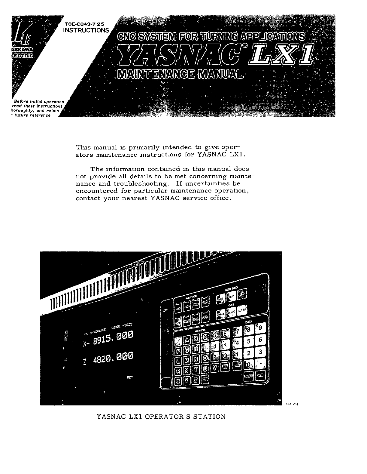
YASNAC
LX1
OPERATOR'S
Hgli
Igllil
0
e
I
0
0
I
STATION
m
Mk
Efc
s
*9
ES
582-231
Page 2
OUTLINE
1.
1.1
COMPONENT
CONTROL
1.2
SYSTEM
MAINTENANCE
1.3
ROUTINE
1.4
1.4.1
1.4.2
1.4.3
1.4.4
TROUBLESHOOTING
2.
2.1
TROUBLE
2.1.1
2.1.2
2.1.3
TROUBLESHOOTING
2.2
2.2.1
2.2.2
TROUBLESHOOTING
2.3
CODES
2.4
SUPPLY
2.4.1
2.4.2
SYSTEM
BLOCK
3
Tape
Control
Servomotor
Battery
Nature
Operations
Unit
NC
of
List
counteracting
28
Check
DC
Power
1
ARRANGEMENT
DIACRAM
INSPECTION
Reader
Panel
and
6
ISOLATION
Circumstances
and
and
Check
Alarm
VOLTAGE
power
Supply
1
OF
YASNAC
INSTRUMENTS
SCHEDULE
5
5
Motor
DC
7
7
Programming
8
BY
ALARM
Codes
Alarm
Supply
10
Codes
WITHOUT
CHECK
Voltage
Voltage
OF
CONTROL
for
Trouble
of
Checks
18
37
Check
YASNAC
4
Spindle
CODES
ALARM
37
Table
4
38
Contents
of
ON-LINE
STATUS
2.5
TICS
Output
3.
3.1
3.2
5
3.2.1
3.2.2
3.3
FUNCTION
2.5.1
2.5.2
Outline
Operating
Signals
2.5.3
(
List
ADJUSTMENTS
ADJUSTMENT
POWER
Tap
)
49
2T
Tap
DISPLAYING
DISPLAY
(DCN
of
Displays
Procedure
39
Standard
of
TRANSFORMER
Changing
Changing
BY
)
38
Input/Output
UPON
PROCEDURES
AND
INSTALLATION
Control
on
Control
on
WRITING
DIAGNOS¬
38
to
Display
Signals
47
CONNECTIONS
Transformer
Transformer
PARAMETERS
Input/
39
47
49
49
50
7
7
9
3.3.1
3.3.2
3.3.3
3.3.4
Data
3.3.5
eter
3.3.6
3.3.7
APPENDIX
Parameter
Parameter
Writing
Tape
51
Punchmg-out
Data
List
List
of
of
PENSATION
Parameter
Input
51
Setting
Parameter
STORED
69
Types
Display
Data
Settinq
of
of
Numbers
LEADSCREW
50
Data
Setting
Numbers
Data
50
50
Data
52
and
and
57
ERROR
parameter
Param¬
COM¬
Page 3
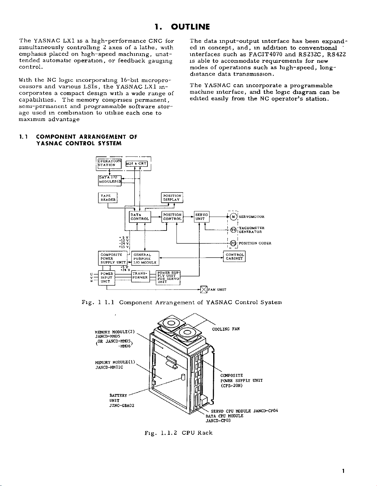
The
YASNAC
simultaneously
emphasis
tended
placed
automatic
control.
the
With
cessors
NC
and
corporates
capabilities.
semi-permanent
used
age
maximum
in
advantage
LX1
controlling
on
operation,
logic
incorporating
various
a
compact
The
and
combination
is
a
high-performance
high-speed
LSIs,
design
memory
programmable
to
2
axes
or
the
with
comprises
utilize
a
of
machining,
feedback
16-bit
YASNAC
wide
a
permanent,
software
each
CNC
lathe,
gauging
micropro¬
LX1
range
one
1.
for
with
unat¬
in¬
of
stor¬
to
OUTLINE
The
data
ed
in
interfaces
is
able
modes
distance
YASNAC
The
machine
edited
input-output
concept,
such
to
accommodate
of
operations
data
interface,
easily
and,
FACIT4070
as
such
transmission.
can
incorporate
and
from
the
interface
addition
m
requirements
the
NC
to
and
as
high-speed,
a
programmable
logic
operators
has
been
conventional
RS232C,
for
diagram
station.
expand¬
RS422
new
long¬
can
*
be
1.1
COMPONENT
YASNAC
CONTROL
ARRANGEMENT
SYSTEM
I
I
OPERATORS
!
STATION
I/O
DATA
(2)
MODULES
TAPE
READER
I
*
12
*15
COMPOSITE
POWER
UNIT
SUPPLY
POWER
U
—
INPUT
V
—
W
UNIT
—
I
1
Fig.
1.1
Component
[MDI
V
5
V
V
V
v
5
OF
«ÿ
1
DATA
CONTROL
GENERAL
PURPOSE
I/O
V
TRANS¬
FORMER
CRT|
I
MODULE
1
|
POSITION
DISPLAY
POSITION
CONTROL
POWER
UNIT
PLY
SERVO
FOR
UNIT
Arrangement
SUP
SERVO
UNIT
of
FAN
UNIT
YASNAC
i
f®
\
|
t
I
I
0j
CONTROL
CABINET
Control
SERVOMOTOR
TACHOMETE:
GENERATOR
POSITION
CODER
System
MODULE
MEMORY
JANCD-MM05
JANCD-MM05
OR
(
MEMORY
JANCD-MM01C
-MM06
MODULE
BATTERY
UNIT
JZNC-GBA02
O
(2)
)
(1)
COOLING
[
FAN
[
[C
[
COMPOSITE
SUPPLY
POWER
(CFS-20N)
UNIT
i
Fig.
\
DATA
JANCD-CP03
CPU
1.2
1.
Rack
SERVO
CPU
CPU
MODULE
MODULE
JANCTHCP04
1
Page 4
1
l
Fig
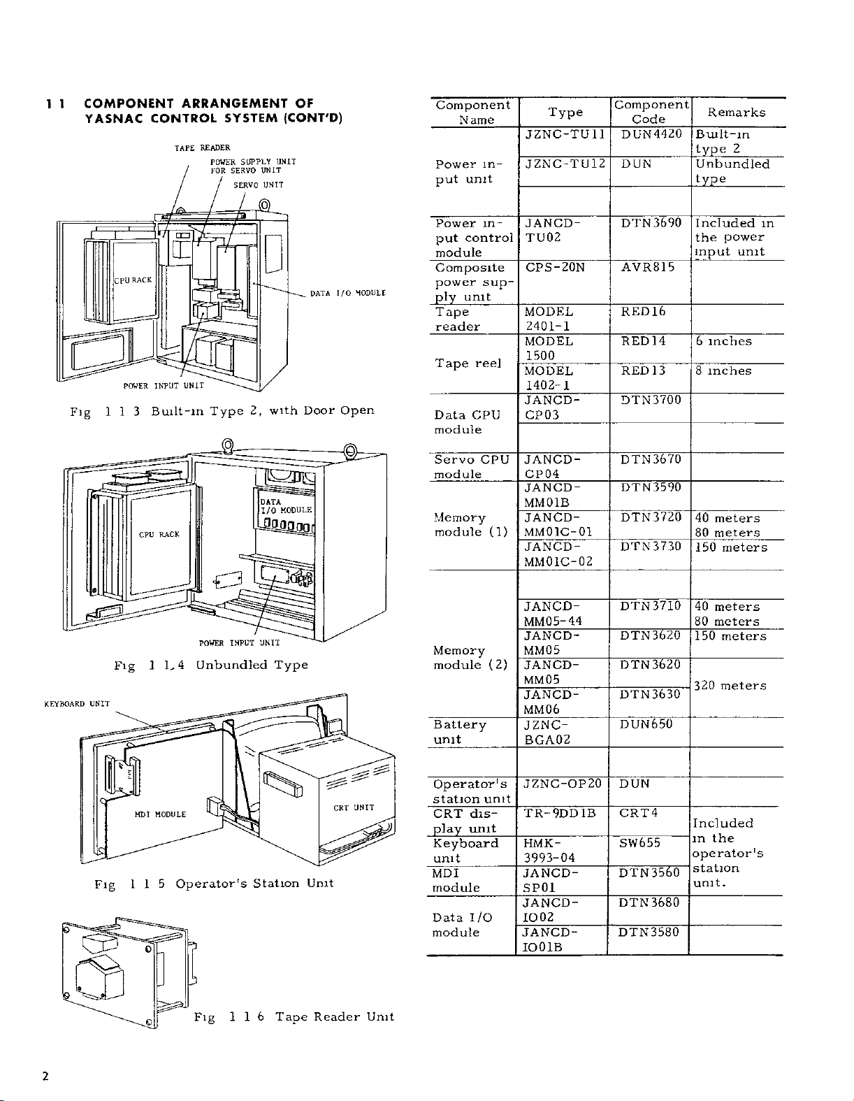
COMPONENT
CPU
RACK
POUER
CONTROL
Vf\
INPUT
Built-m
RACK
CPU
YASNAC
I
113
ARRANGEMENT
SYSTEM
TAPE
READER
SUPPLY
POWER
SERVO
FOR
SERVO
LIU
QIMPTT
UNIT
2,
Type
(q)
]]gZIIg
UNII
UNIT
UNIT
_
with
DATA
I/O
OF
(CONT'D)
DATA
Door
MODULE
I/O
Open
P
MODULE
Component
Name
Power
unit
put
Power
control
put
module
Composite
power
ply
T
sup-
unit
ape
reader
reel
Tape
CPU
Data
module
Servo
module
CPU
Memory
module
in¬
in¬
(1)
Type
JZNC-TU
JZNC-TU12
JANCD-
TU02
CPS-20N
MODEL
2401-1
MODEL
1500
MODEL
1402-1
JANCD-
CP03
JANCD-
CP04
JANCD-
MM01B
JANCD-
MM01C-01
JANCD-
MM01C-02
Component
1
1
Code
DUN
4420
DUN
3690
DTN
AVR815
RED16
RED
14
13
RED
DTN3700
DTN3670
DTN3590
3720
DTN
DTN
3730
Remarks
Built-in
type
2
Unbundled
type
Included
power
the
6
unit
inches
inches
meters
meters
meters
input
8
40
80
150
in
KEYBOARD
e
Q
UNIT
Us
Fig
iSh.
Fig
*
I
115
MDI
1
MODULE
o
o
LI
Operator's
3
Fig
INPUT
POWER
Unbundled
116
UNIT
Type
Station
Tape
Unit
Reader
CRT
UNIT
Unit
Memory
module
Battery
unit
Operator's
station
CRT
dis-
play
unit
Keyboard
unit
MDI
module
Data
I/O
module
(2)
unit
JANCD-
MM05-
JANCD-
44
MM05
JANCD-
MM05
JANCD-
MM06
JZNC-
BGA02
JZNC-OP20
TR-9DD
HMK-
3993-04
JANCD-
SP01
JANCD-
1002
JANCD-
IO01B
IB
DTN3710
3620
DTN
3620
DTN
DTN3630
DUN650
DUN
4
CRT
SW655
DTN
3560
3680
DTN
DTN3580
40
meters
meters
80
150
meters
meters
320
Included
the
in
operator's
station
unit.
2
Page 5
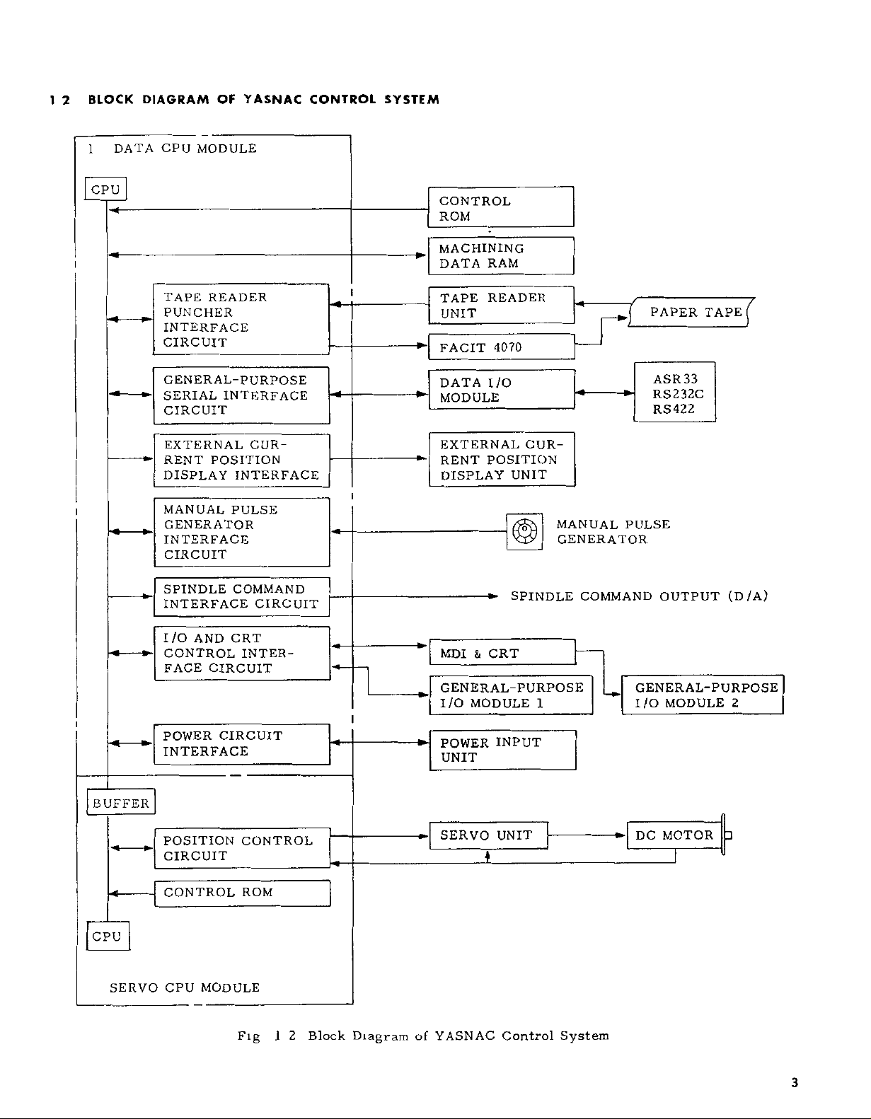
DATA
DIAGRAM
CPU
BLOCK
1
2
1
OF
MODULE
YASNAC
CONTROL
SYSTEM
CPU
CONTROL
ROM
-*ÿ
TAPE
PUNCHER
INTERFACE
CIRCUIT
GENERAL-PURPOSE
SERIAL
CIRCUIT
EXTERNAL
RENT
DISPLAY
MANUAL
GENERATOR
INTERFACE
CIRCUIT
SPINDLE
INTERFACE
READER
INTERFACE
CUR¬
POSITION
INTERFACE
PULSE
COMMAND
CIRCUIT
l
i
MACHINING
DATA
TAPE
UNIT
FACIT
DATA
MODULE
EXTERNAL
RENT
DISPLAY
RAM
READER
4070
I/O
POSITION
CUR¬
UNIT
SPINDLE
r
*ÿ
MANUAL
GENERATOR
COMMAND
PULSE
r
PAPER
ASR33
RS232C
RS422
OUTPUT
TAPE
r
(D/A)
-4
BUFFER
-<ÿ
CPU
SERVO
AND
I/O
CONTROL
FACE
POWER
CRT
CIRCUIT
CIRCUIT
INTERFACE
POSITION
CIRCUIT
CONTROL
MODULE
CPU
INTER¬
CONTROL
ROM
I
Fig
2
Block
--
I
Diagram
&
MDI
GENERAL-PURPOSE
I/O
POWER
UNIT
SERVO
CRT
MODULE
INPUT
UNIT
1
of
YASNAC
Control
1
System
GENERAL-PURPOSE
I/O
DC
MODULE
MOTOR
2
3
3
Page 6
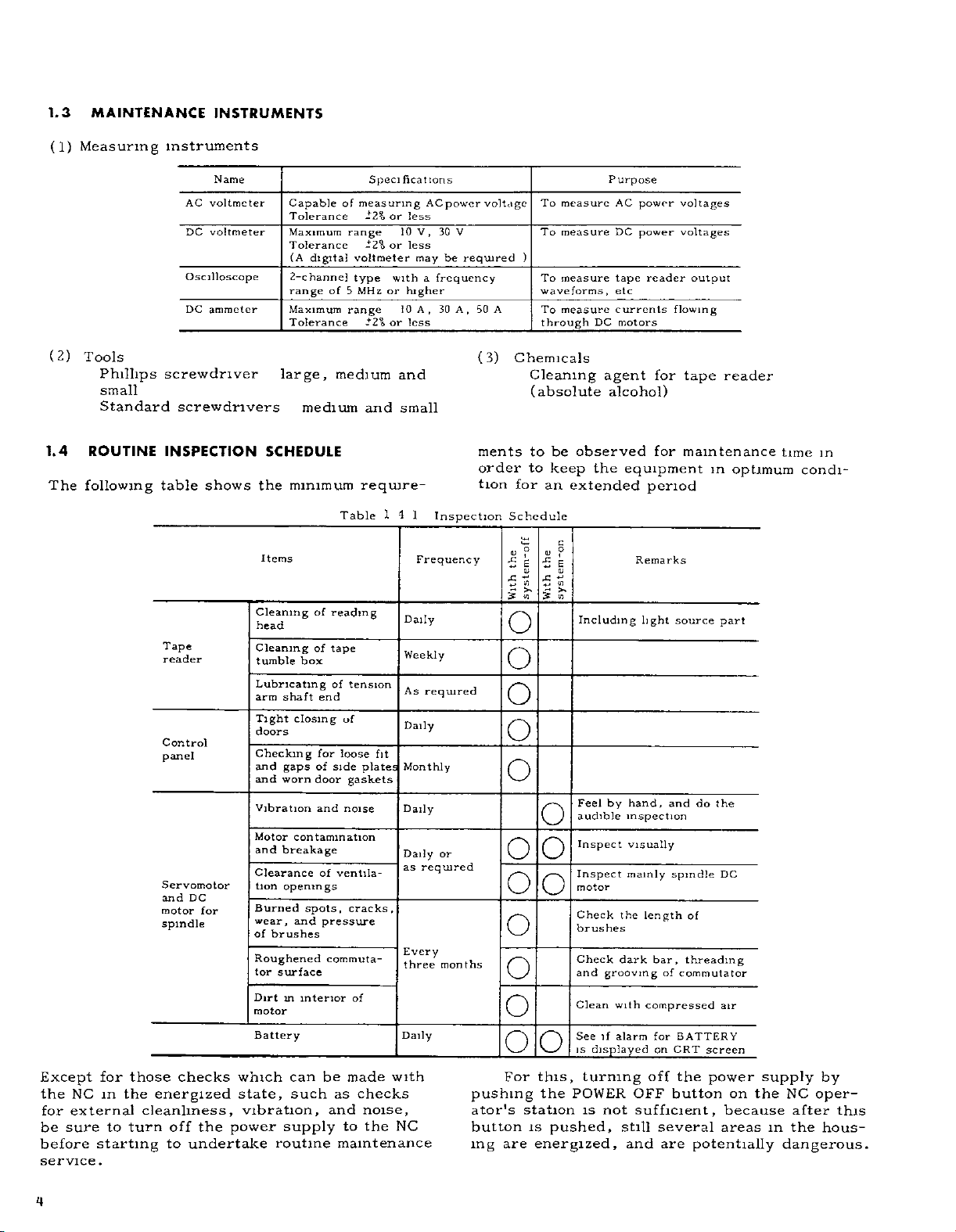
1.3
MAINTENANCE
INSTRUMENTS
(1)
(2)
1.4
The
Measuring
Tools
Phillips
small
Standard
ROUTINE
following
instruments
Name
AC
voltmeter
DC
voltmeter
Oscilloscope
DC
ammeter
screwdriver
screwdrivers
INSPECTION
table
shows
Tape
reader
Control
panel
Servomotor
DC
and
motor
for
spindle
Capable
Tolerance
Maximum
T
olerance
(A
2-channe]
range
Maximum
Tolerance
large,
medium
SCHEDULE
the
minimum
Items
Cleaning
head
Cleaning
tumble
box
Lubricating
arm
shaft
Tight
closing
doors
Checking
gaps
and
and
worn
Vibration
Motor
contamination
and
breakage
Clearance
tion
openings
Burned
wear,
of
Roughened
tor
Dirt
motor
Battery
and
brushes
surface
m
spots
interior
digital
of
of
end
for
of
door
and
of
pressure
commuta¬
of
measuring
range
voltmeter
type
b
of
MHz
range
medium
Table
reading
tape
of
tension
of
loose
side
gaskets
noise
ventila¬
,
cracks,
of
Specifications
-2%
or
less
10
less
or
-2%
with
or
higher
10A,30
or
less
-2%
and
and
small
require-
14
Daily
Weekly
As
Daily
fit
Monthly
plates
Daily
Daily
as
Every
three
Daily
ACpower
V,
30
may
a
frequency
1
Inspection
Frequency
required
or
required
months
be
V
required
50
,
A
(3)
voltage
A
ments
order
tion
To
To
)
To
waveforms,
To
through
Chemicals
Cleaning
(absolute
to
to
for
an
Schedule
V
s:
Ife
V
=
5T
3
I!
o
o
o
o
o
o
o
o
o
o
o
o
o
oo
measure
measure
measure
measure
be
keep
extended
g
£
P
urpose
AC
DC
tape
etc
currents
DC
motors
agent
alcohol)
observed
the
Including
by
Feel
audible
Inspect
Inspect
motor
Check
the
brushes
Check
dark
and
grooving
Clean
with
See
alarm
if
is
displayed
power
power
reader
for
for
equipment
period
Remarks
light
hand,
inspection
visually
mainly
length
bar,
of
compressed
for
on
voltages
voltages
output
flowing
tape
maintenance
source
and
do
spindle
of
threading
commutator
BATTERY
CRT
screen
reader
in
part
the
DC
air
optimum
time
in
condi¬
Except
the
for
be
before
service
4
NC
externa]
sure
for
the
in
to
starting
.
those
energized
cleanliness,
turn
checks
off
to
undertake
the
which
state,
vibration,
power
can
such
supply
routine
be
made
as
checks
and
noise,
to
the
maintenance
with
NC
For
pushing
ator's
button
are
ing
this,
the
station
pushed,
is
energized,
turning
POWER
not
is
off
OFF
sufficient,
still
and
the
button
several
are
power
on
because
areas
potentially
supply
the
in
dangerous.
NC
after
the
by
oper¬
this
hous¬
Page 7
1
(
4.1
1)
A
B
(2)
A
B
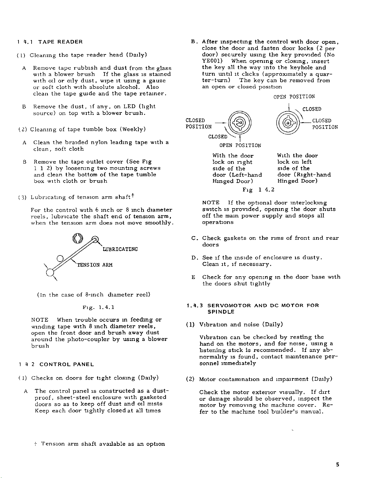
(3)
TAPE
Cleaning
Remove
a
with
with
oil
soft
or
the
clean
Remove
source)
Cleaning
Clean
,
clean
Remove
112)
and
clean
with
box
Lubricating
the
For
reels,
when
lubricate
the
READER
the
tape
blower
or
cloth
tape
the
on
of
the
braided
soft
the
loosening
by
the
cloth
control
tension
tape
rubbish
brush
dust,
oily
with
guide
dust,
withablower
top
tumble
tape
cloth
tape
bottom
or
of
tension
with
the
reader
absolute
if
any,
nylon
outlet
two
brush
6
shaft
arm
and
If
wipe
and
of
arm
inch
does
head
dust
the
it
alcohol.
the
on
box
leading
cover
mounting
the
shaft"ÿ
or
end
not
(Daily)
from
glass
using
retainer.
tape
(light
LED
brush.
(Weekly)
tape
(See
tumble
tape
inch
8
of
tension
move
the
stained
is
a
gauze
Also
with
Fig
screws
diameter
smoothly.
glass
arm,
After
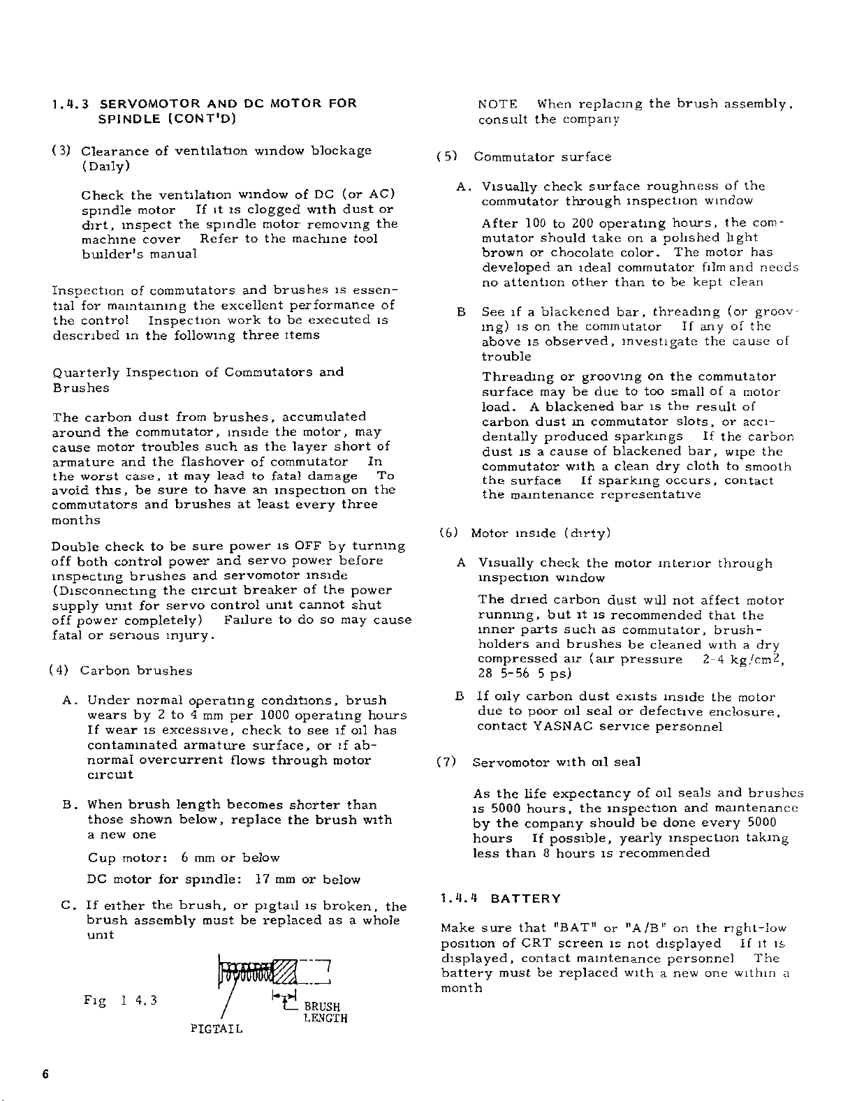
B.
CLOSED
close
door)
YE001)
the
key
turn
ter-turn)
an
open
inspecting
the
door
securely
When
all
until
it
or
POSITION
a
CLOSED
OPEN
With
lock
side
door
POSITION
the
on
of
the
(Left-hand
Hinged
NOTE
switch
the
off
operations
If
is
provided,
mam
the
the
clicks
The
closed
door
right
Door)
Fig
power
the
control
fasten
and
using
opening
into
way
(approximately
can
key
position
4.2
1
optional
opening
supply
the
door
key
or
the
be
OPEN
With
lock
side
door
Hinged
door
with
locks
provided
closing,
keyhole
removed
POSITION
CLOSED
the
on
left
the
of
(Right-hand
Door)
interlocking
the
door
stops
and
door
(2
insert
and
a
quar¬
from
CLOSED
POSITION
door
shuts
all
open,
per
(No
1
(
4
1)
A
\
(In
NOTE
winding
open
around
brush
2
CONTROL
Checks
The
proof,
doors
Keep
Q
\
the
When
tape
the
the
on
control
sheet-steel
so
each
TENSION
of
case
trouble
with
front
door
photo-coupler
PANEL
doors
panel
to
as
keep
door
8-mch
Fig.
8
for
is
enclosure
tightly
LUBRICATING
ARM
diameter
1.4.1
occurs
inch
diameter
and
brush
by
tight
closing
constructed
dust
off
closed
in
using
with
and
reel)
feeding
away
as
oil
all
at
reels,
dust
blower
a
(Daily)
dust-
a
gasketed
mists
times
or
C.
D.
E
1.4.3
(1)
(2)
Check
doors
See
if
Clean
Check
the
doors
SERVOMOTOR
SPINDLE
Vibration
Vibration
on
hand
listening
normality
sonnel
Motor
Check
or
motor
fer
contamination
damage
by
the
to
gaskets
inside
the
it,
if
necessary.
for
any
shut
and
noise
can
be
motors,
the
stick
is
found,
is
immediately
motor
the
should
removing
machine
the
of
enclosure
rims
on
opening
tightly
DC
AND
(Daily)
checked
and
recommended.
contact
and
exterior
observed,
be
the
machine
builder's
tool
of
in
the
MOTOR
by
resting
for
noise,
maintenance
impairment
visually.
front
is
dusty.
door
If
inspect
cover.
manual.
and
base
FOR
the
using
any
(Daily)
If
rear
with
a
ab¬
per¬
dirt
the
Re¬
t
Tension
arm
shaft
available
as
an
option
5
Page 8
1.4.3
SERVOMOTOR
SPINDLE
(CONT'D)
AND
DC
MOTOR
FOR
NOTE
consult
When
the
replacing
company
the
brush
assembly,
(3)
Clearance
(Daily)
Check
spindle
dirt,
machine
builder's
Inspection
for
tial
the
maintaining
control
described
Quarterly
Brushes
carbon
The
around
cause
the
motor
armature
worst
the
avoid
this,
commutators
months
both
check
control
Double
off
inspecting
(Disconnecting
power
or
Carbon
Under
unit
serious
supply
off
fatal
(4)
A.
wears
If
wear
contaminated
normal
circuit
When
B.
those
a
new
Cup
DC
motor
C.
If
either
brush
unit
Fig
14.3
ventilation
of
ventilation
the
motor
inspect
cover
manual
commutators
of
Inspection
the
dust
following
from
in
Inspection
commutator,
troubles
and
the
case,
be
and
to
it
sure
brushes
be
power
brushes
the
servo
for
completely)
injury.
brushes
normal
2to4
by
is
excessive,
overcurrent
brush
length
shown
one
motor:
for
the
assembly
it
If
the
spindle
Refer
the
of
brushes,
such
flashover
may
to
have
sure
and
circuit
control
operating
mm
armature
below,
6
mm
spindle:
brush,
must
PIGTAIL
window
window
is
clogged
motor
to
the
and
excellent
to
work
three
Commutators
inside
the
as
of
to
lead
an
at
least
power
and
servo
servomotor
breaker
unit
Failure
conditions,
1000
per
check
surface,
flows
becomes
replace
or
below
17
or
pigtail
be
replaced
blockage
DC
of
with
removing
machine
brushes
performance
executed
be
items
and
accumulated
motor,
the
layer
commutator
fatal
damage
inspection
every
OFF
is
by
power
inside
of
the
cannot
to
do
so
operating
to
see
or
through
shorter
the
brush
mm
or
below
broken,
is
as
]
BRUSH
LENGTH
(or
dust
tool
essen¬
is
may
short
on
three
turning
before
power
shut
may
brush
oil
if
ab¬
if
motor
than
a
AC)
or
the
of
is
of
In
To
the
cause
hours
has
with
whole
the
5)
(
A.
B
(6)
Motor
A
B
(7)
Servomotor
As
is
by
hours
less
1.4.4
Make
position
displayed,
battery
month
Commutator
Visually
commutator
After
100
mutator
brown
or
developed
no
attention
See
mg)
above
a
if
on
is
is
trouble
Threading
surface
load.
carbon
A
dust
dentally
is
dust
commutator
surface
the
the
maintenance
inside
Visually
inspection
The
dried
running,
inner
parts
holders
compressed
28
56
5-
oily
If
due
contact
the
5000
the
carbon
poor
to
YASNAC
life
hours,
company
If
than
BATTERY
sure
that
CRT
of
contact
must
surface
check
through
200
to
should
chocolate
an
other
blackened
the
observed,
or
be
may
blackened
m
produced
cause
a
with
(dirty)
check
window
carbon
but
such
and
brushes
air
5
ps)
oil
with
expectancy
possible,
hours
8
"BAT”
screen
be
replaced
surface
operating
take
color.
commutator
ideal
than
bar,
commutator
investigate
grooving
due
to
bar
commutator
sparkings
of
blackened
clean
a
If
sparking
representative
motor
the
dust
is
it
recommended
commutator,
as
(air
pressure
dust
exists
or
seal
service
seal
oil
the
inspection
should
yearly
recommended
is
"A/B"
or
is
maintenance
with
roughness
inspection
on
a
polished
to
threading
on
too
is
dry
occurs,
interior
will
be
cleaned
inside
defective
personnel
oil
of
be
done
not
displayed
a
window
hours,
motor
The
film
be
kept
If
any
the
the
commutator
small
the
result
slots
If
bar,
cloth
not
affect
that
with
2-4
enclosure,
seals
and
every
inspection
the
on
personnel
new
one
the
of
com¬
the
light
has
and
clean
(or
groov
of
the
cause
of
motor
a
of
,
or
acci¬
the
carbon
wipe
to
smooth
contact
through
motor
the
brush-
a
dry
kg
/cm
the
motor
and
brushes
maintenance
5000
taking
right-low
If
The
within
needs
the
2
is
it
of
,
a
6
Page 9
2.1
TROUBLE
to
Try
the
trouble
•
the
of
Type
In
In
the
NATURE
what
what
latmg
serviceman
fying
time
2.1.1
TROUBLE
(1)
operate
What
trouble
Was
positioning
Was
Was
Was
What
In
What
Does
the
Is
Is
the
(2)
Frequency
When
when
How
(3)
Recurrence
Run
trouble
the
being
able
Verify
tributed
Increase
Ask
under
fully
analyze
occurred
trouble
calledin
following
system
your
of
trouble
mode
mode(s)
7
was
occurred7
the
positioning
tool
the
the
feedrate
an
auxiliary
was
which
was
the
trouble
trouble
did
other
often
program
the
several
NC
unit
programmed.
to
external
the
values
or
the
operator
which
ISOLATION
and/or
to
points
AND
did
the
display
error,
path
the
alarm
program
sequence
the
trouble
related
associated
of
trouble
the
trouble
machines
did
it
trouble
of
times
and
disturbances
offset
being
decrease
the
the
circumstances
This
is
necessary
for
having
correct
CIRCUMSTANCES
the
does
incorrect
displayed
erroneous
will
trouble
the
of
MDI
the
minimize
system
&
position
(by
correct7
the
used7
trouble
function
number7
did
number7
a
recur
in
particular
to
tool
with
develop7
m
were
occur?
experienced
that
tape
Check
the
them
trouble
and
remaining
compare
Is
values
stored.
override
the
explain
to
trouble
the
occurred.
2.
TROUBLESHOOTING
m
for
YASNAC
the
trouble.
the
OF
occur7
normally
CRT
when
(error
axis,
values7
much)
how
occur7
changing7
feedrate7
(Did
it
operation7)
the
values
with
those
attribut¬
7
value.
circumstances
which
Veri¬
down
mode7
occur
the
dis¬
ISO-
the
m
AND
2.1.2
(
1)
OPERATIONS
Operations
Was
the
there
Was
the
Was
operator
recent
a
operator
PROGRAMMING
properly
change
well
familiar
trained7
of
operators?
with
CHECKS
the
pro¬
gram7
under
properly
coded7
before
incremental
be
selected?
function
or
erroneous
comple¬
set?
proper¬
the
7
the
absolute
the
other
the
used7
the
the
there
program
program
tool
operating
optional
tape
program
Was
tion
Was
or
•
Was
•
Can
Was
ly
Was
Was
7
•
Were
interrupted
placed
command7
compensation
block
correctly
properly
any
inadvertent
modes
skip
set7
operations7
(2)
Punched
•
Was
•
Was
•
Were
*
Was
this
Was
•
Was
Was
Programming
(3)
Is
Was
instruction
•
Did
•
Did
•
Was
the
tape
tape
the
the
tape
tapes
program
the
operation7
tape
the
the
tape
black
a
program
the
program
the
trouble
trouble
the
check
a
contaminated7
or
bent
properly
successfully
correctly
puncher
used7
tape
new?
formulated
manual7
occur
occur
list
made
crimpled?
spliced7
punched?
operating
a
in
particular
m
subprogram?
a
and
used
run
normally7
according
for
prior
tape
to
to
block?
the
verification7
(4)
Settings
adjustments
the
or
operation?
Were
made
Was
there
a
prior
fuse
any
to
starting
blown7
corrections
7
Page 10
2.1.2
(5)
(6)
OPERATIONS
(CONT'D)
•
Was
•
Was
Was
What
Was
board)
Was
Was
Was
Was
External
Was
justed
Was
usted
adj
Was
there
Is
frequency
machine,
range’
Was
there
nearby
there
Is
ed
similar
Has
the
inside
the
Has
this
Ambient
What
there
Was
Was
the
Was
there
the
in
Were
Was
the
an
emergency
the
machine
an
alarm
was
the
alarm
’
MODE
the
override
the
the
machine
the
feed
the
machine
’
the
control
’
NC
the
’
user
the
same
unit’
conditions
was
tape
immediate
there
system
the
factors
unit
any
sewing
welding
any
any
failures
NC
the
any
any
any
other
AND
stop
tool
ready
in
state
lamp
number’
lit
alarm
switch
set
to
set’
lock
set’
hold
tool
recently
cabinet
recently
source
noise
machine,
machine)
new
machine
NC
in
your
made
an
unit’
trouble
occured
temperature’
abrupt
oil
or
contaminated’
cutting
reader
area’
vibrations’
exposed
PROGRAMMING
maintained’
to
operate’
effect’
module
a
on
in
normal
position’
"0"’
repaired
recently
repaired
(e
g
repaired
,
crane,
electrical
within
interference
recently
that
has
unit
factory’
attempt
at
adjustments
previously
temperature’
change
in
splashed,
fluid
to
the
direct
CHECKS
(on
or
adjusted’
discharge
installed
develop¬
sunlight’
print
or
high
ad¬
or
with
(4)
(5)
(2)
(
3)
Was
Was
Did
interior’
Tape
•
Was
What
forms
Control
Was
Was
(Was
port
Was
Composite
Was
Were
+24
Was
•
Was
Was
•
Was
•
Was
cabinet
How
Was
voltage
Was
interlock
Is
there
amount
machine,
ing
Grounding
Was
Was
the
tape
the
unit
machining
any
reader
the
tape
were
from
unit
the
control
the
fan
the
air
normal’)
the
interior
the
input
the
output
V)
each
voltage
fuse
a
the
circuit
the
shield
the
wiring
’
much
there
any
’
the
front
m
any
current
of
grounding
the
shield
reader
operated
reader
the
characteristics
the
interior
motor
flow
power
voltage
blown’
properly
did
the
significant
or
effect)
machine
electrical
properly
grounding
chips
tape
unit
operating
from
damaged
supply
voltages
within
breaker
properly
input
rear
’
m
door
closed’
with
its
enter
contaminated’
reader’
interior
normally’
the
cooling
by
unit
normal’
normal
tolerance’
tripped’
grounded’
inside
voltage
drop
door
open
that
consumes
the
factory
discharge
connected’
proper’
door
open’
the
cabinet
of
the
wave¬
contaminated
air
corrosive
(
V
+5
the
control
fluctuate’
in
input
(with
a
(e
g
machine)’
’
exhaust
gas’
,
+12
door
large
,
weld¬
V,
2.1.3
(1)
8
NC
Control
the
Was
the
Was
UNIT
unit
MDI
tape
CHECK
exterior
CRT
&
reader
unit
kept
normal’
clean’
(6)
Cables
Were
Was
Was
Was
cable
any
any
any
connectors
internal
external
cable
cable
cable
broken
securely
damaged’
damaged’
contaminated’
or
inserted’
Page 11
(7)
Modules
(on
printed
circuit
board)
1
Depress
the
(ALM)
key
•
•
(8)
•
(9)
(10)
1.1
an
If
"A/B"
line
function.
the
lowing
all
Were
Were
plug
What
was
Were
connections
modules
&
MDI
Were
push
Was
the
Was
the
Parameters
Did
the
parameter
Interface
Were
the
installed7
ly
Was
the
Were
the
equipped
Were
the
DGN
the
TROUBLE
alarm
(for
the
of
alarm
condition
operations.
modules
connectors
the
correct7
CRT
buttons
flat
flat
actual
table
power
cable
relay,
with
I/O
(diagnostic)
SHOOTING
condition
battery
CRT
this
In
revision
unit
keyboard
cable
parameters
attached
cable
positively
solenoid,
a
noise
signals
alarm)
screen
case,
will
securely
(on
freely
free
normally
occurs,
regardless
detailed
be
installed7
properly
letter7
cable)
flat
operable7
operable
of
defects7
match
the
to
NC
and
shielded7
motor,
suppressor7
function7
BY
ALARM
display
a
blinks
information
displayed
secured7
between
7
those
NC
cable
etc
generated
CODE
on
the
the
of
by
m
unit7
separate¬
each
"ALM"
bottom
mode
fol¬
the
of
the
by
will
This
alarm
and
importance,
cause
messages
with
up
the
to
to
4
pairs
appear
most
serious
of
alarm
in
order
one
codes
of
at
the
top.
NOTE
appears
There
330:
310:
291:
013:
an
In
taking
need
no
is
EMERGENCY
SERVO
OO
OT
PROG
alarm
priority
to
OFF
ERROR
state
over
operate
STOP
CNO
,
the
any
the
0001
ADDRESS)
BUF
alarm
other
(PAGE)
B
N0017
ALM
screen
T
display
key
L
and
alarm
reset
alarm
it
Messages
and
state
Notice
n
820,"
as
depress
and
that
"830"
of
the
follows:
Alarm
2
RESET
alarm
alarm
"840"
2
cause
the
key,
display
codes
are
function
Fig
Eliminate
the
the
the
or
and
selected
Codes
of
and
will
"800,"
displayed
key.
the
the
be
"810,
regardless
or
The
2.
alarm
codes
are
categorized
Alarm
000
100
200
300
400
500
600
700
800
900
Table
No
099
to
to
199
to
299
to
399
to
499
to
599
to
699
799
to
to
899
999
to
Spindle
at
Stop
at
Stop
Immediate
Immediate
Immediate
NC
system
Operation
block
block
stop
stop
stop
stop
end
end
2.2
Tape
Macro,
output
Overtravel,
positioning,
Servo,
FG,
Sequence
Sequencer
CPU
Off-line
format
operation,
error,
emergency
RPG
error,
error
Type
error
reference
machine
error
message
RAM
of
Alarm
alarm
external
sequence
stop,
(2)
error,
point
ready
input/
error
overload
ROM
(1)
return,
error
9
Page 12
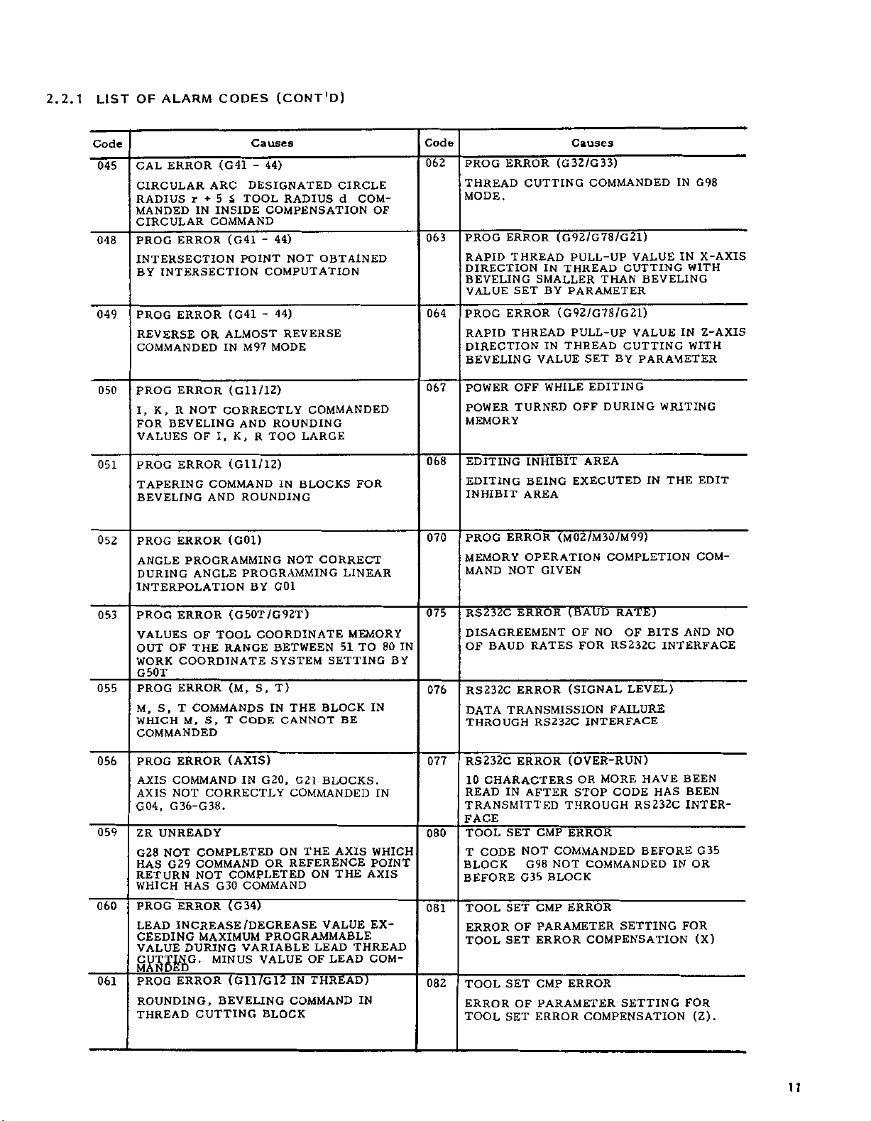
2.2,1
LIST
OF
ALARM
CODES
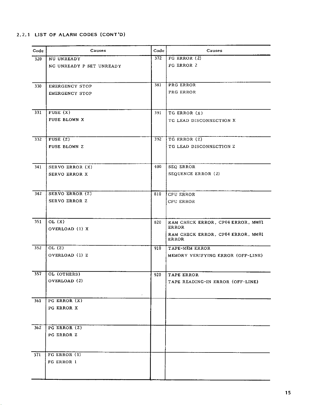
Code
001
002
005
010
Oil
012
UNREADY
ZR
REFERENCE
COMPLETED
UNREADY
ZR
REFERENCE
COMPLETED
RESET
CYCLE
RESET
TH
TAPE
TV
TAPE
UNREADY
START
BUTTON
ERROR
HORIZONTAL
ERROR
VERTICAL
OVERFLOW
BUFFER
BLOCK
CAPACITY
(128
Causes
(X)
POINT
RETURN
X
(Z)
POINT
Z
RETURN
(AFTER
WITHOUT
AFTER
PARITY
PARITY
(I28CH)
OVERFLOW
CHARACTERS)
NOT
NOT
EDITING)
DEPRESSING
EDITING
ERROR.
ERROR
IN
Code
024
026
PROG
ERROR
UNUSABLE
RADIUS
NOSE
ERROR
PROG
RISE
ERROR
Causes
(G
,
G41
CODE
G
COMMANDED
COMPENSATION
(G41-44)
NOSE
IN
44)
-
RADIUS
DURING
COMPEN¬
SATION
027
PROG
ERROR
ERROR
SATION
POLATION
030
031
034
A
ERROR
PROG
OR
NO
F
ERROR
PROG
CIRCLE
CIRCULAR
PROG
ERROR
CIRCULAR
(G41
DURING
(ERROR
MODE)
(F/E)
E
COMMAND
(R=0)
RADIUS
WITH
ARC
(G02/03)
ARCRDESIGNATION
44)
-
RADIUS
NOSE
IN
CIRCULAR
IN
0
COMMAND
COMPEN¬
INTER¬
COMMAND
FEED
COMMANDED
ERROR
IN
013
014
015
017
020
021
ERROR
PROG
ADDRESS
DRESS
DATA
PROG
SIGN
USED
PROG
UNUSABLE
PLUS
COMMAND
ERROR
AND
ERROR
CHARACTER
INSIGNIFICANT
PROG
ERROR
INPUT
CHARACTERS)
PROG
UNUSABLE
INCLUDED
PROG
G
GRAMMED
ERROR
CODES
DATA
G
IN
ERROR
IN
SIMULTANEOUSLY
(NO
ADDRESS)
NO
DATA
OR
C-,"
n
"
(UNUSABLE
DATA
(8
DIGITS)
OVERFLOW
(G)
CODE
OPTIONS
(G)
MODAL
AND
NO
ADDRESS
”)
"
NOT
CORRECTLY
CH)
PROGRAMMED
AREA
(MORE
OR
G
CODE
PROGRAMMED
AND
*
NEXT
THAN
NOT
GROUPS
IN
A
AD¬
PLUS
8
PRO¬
BLOCK.
IN
035
036
037
040
041
042
PROG
ERROR
TOO
LARGE
POSITION
TOOL
PROG
ERROR
TOO
LARGE
WHEN
OFFSET
NO
P
DESIGNATION
ERROR
PROG
LARGE
TOO
SYSTEM
ERROR
PROG
P
ORQNOT
P
IN
ERROR
NOT
PROGRAMMED
IS
BLOCK
PROG
NO
PROGRAM
FOUND
M98
PROG
,
M99,
WHEN
G65,
ERROR
SUBPROGRAM
(G65/G66)
OFS)
(T
T
OF
OFS
NO
OFFSET
(P-G10)
(NUMBER
P
IS
PROGRAM-INPUT
(G10)
WHEN
R
DESIGNATION)
WORK
PROGRAM-INPUT
BLOCK
A
G65/66)
(M98,
IN
G65/G66
PROGRAMMED
(SEQUENCE
NO
PROGRAMISCALLED
G66,
(M98,
(M98)
FIVE-NESTED
M,
G,
G65/66
OR
MACRO
CODE
FOR
OR
COORDINATE
OR
FORMAT
BLOCK
IN
M98
)
NOT
NO
BY
AND
T
NEST)
CALL
10
Page 13
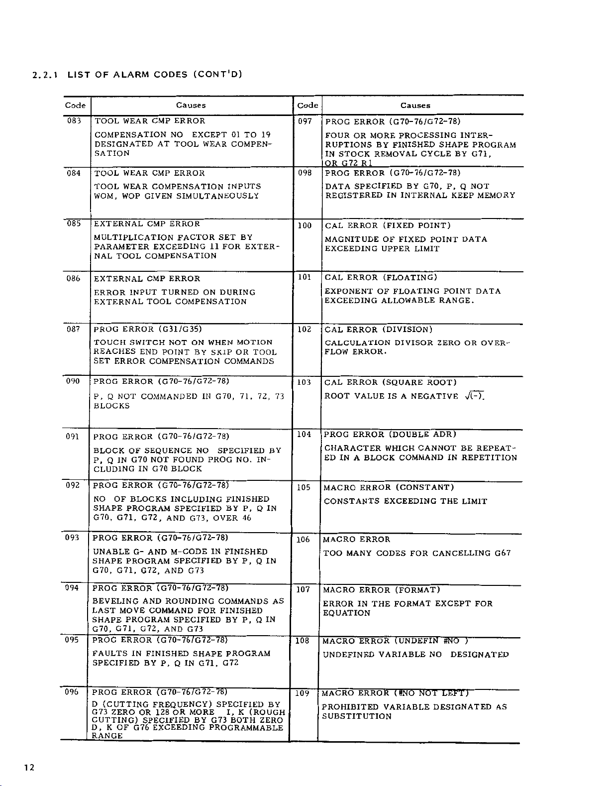
2.2.1
LIST
OF
ALARM
CODES
(CONT'D)
Code
045
048
049
050
051
052
053
055
ERROR
CAL
CIRCULAR
RADIUS
MANDED
CIRCULAR
PROG
INTERSECTION
BY
INTERSECTION
PROG
REVERSE
COMMANDED
PROG
K,
I,
BEVELING
FOR
VALUES
PROG
TAPERING
BEVELING
PROG
ANGLE
DURING
(G41
ARC
+
5
r
INSIDE
IN
COMMAND
ERROR
ERROR
OR
IN
ERROR
R
ERROR
ERROR
CORRECTLY
NOT
I,
OF
COMMAND
AND
PROGRAMMING
ANGLE
INTERPOLATION
ERROR
PROG
TOOL
VALUES
OUT
WORK
G50T
PROG
M,
WHICH
COMMANDED
OF
THE
OF
COORDINATE
ERROR
S,
T
COMMANDS
S,
M,
Causes
44)
-
DESIGNATED
S
<G41
POINT
RADIUS
TOOL
COMPENSATION
44)
-
NOT
COMPUTATION
(G41
ALMOST
(Gll/12)
(Gll/12)
(G01)
44)
-
MODE
M97
ROUNDING
AND
K,
TOO
R
ROUNDING
REVERSE
IN
NOT
PROGRAMMING
G01
BY
(G50T/G92T)
COORDINATE
RANGE
(M,
BETWEEN
SYSTEM
T)
S.
IN
CANNOT
CODE
T
CIRCLE
d
OBTAINED
COMMANDED
LARGE
BLOCKS
CORRECT
LINEAR
51
SETTING
THE
BLOCK
BE
COM¬
OF
FOR
MEMORY
TO
80
BY
IN
IN
Code
062
PROG
THREAD
MODE
PROG
063
RAPID
DIRECTION
BEVELING
VALUE
PROG
064
RAPID
DIRECTION
BEVELING
067
POWER
POWER
MEMORY
EDITING
068
EDITING
INHIBIT
070
PROG
MEMORY
MAND
075
RS232C
DISAGREEMENT
OF
RS232C
076
DATA
THROUGH
ERROR
CUTTING
.
ERROR
THREAD
IN
SMALLER
SET
BY
ERROR
THREAD
IN
VALUE
WHILE
OFF
TURNED
INHIBIT
BEING
AREA
ERROR
OPERATION
GIVEN
NOT
ERROR
BAUD
RATES
ERROR
TRANSMISSION
RS232C
Causes
(G32/G33)
COMMANDED
(G92/G78/G21)
PULL-UP
THREAD
THAN
PARAMETER
(G92/G78/G21)
PULL-UP
THREAD
(M02/M30/M99)
BY
SET
EDITING
DURING
OFF
AREA
EXECUTED
COMPLETION
FOR
RATE)
NO
RS232C
(BAUD
OF
(SIGNAL
FAILURE
INTERFACE
VALUE
CUTTING
BEVELING
VALUE
CUTTING
PARAMETER
WRITING
IN
THE
BITS
OF
INTERFACE
LEVEL)
IN
IN
IN
G98
WITH
WITH
EDIT
COM¬
AND
X-AXIS
Z-AXIS
NO
056
059
060
061
ERROR
PROG
AXIS
COMMAND
AXIS
NOT
G04,
G36-G38.
UNREADY
ZR
NOT
G28
G29
HAS
RETURN
WHICH
PROG
LEAD
CEEDING
VALUE
CUTTING
MANDED
PROG
ROUNDING,
THREAD
HAS
ERROR
INCREASE/DECREASE
DURING
ERROR
(AXIS)
CORRECTLY
COMPLETED
COMMAND
COMPLETED
NOT
G30
(G34)
MAXIMUM
MINUS
(G11/G12
BEVELING
CUTTING
G20,
IN
G21
COMMANDED
THE
ON
REFERENCE
OR
COMMAND
PROGRAMMABLE
VARIABLE
VALUE
IN
ON
OF
THREAD)
COMMAND
BLOCK
BLOCKS.
AXIS
THE
VALUE
LEAD
LEAD
IN
WHICH
POINT
AXIS
EX¬
THREAD
COM-
IN
077
080
081
082
RS232C
10
READ
ERROR
CHARACTERS
AFTER
IN
TRANSMITTED
FACE
SET
TOOL
T
CODE
BLOCK
BEFORE
TOOL
ERROR
TOOL
TOOL
ERROR
TOOL
CMP
NOT
G98
G35
SET
CMP
OF
PARAMETER
ERROR
SET
SET
CMP
OF
PARAMETER
ERROR
SET
(OVER-RUN)
MORE
OR
STOP
THROUGH
ERROR
COMMANDED
NOT
COMMANDED
BLOCK
ERROR
COMPENSATION
ERROR
COMPENSATION
HAVE
CODE
RS232C
BEFORE
SETTING
SETTING
HAS
BEEN
BEEN
INTER¬
IN
FOR
FOR
G35
OR
(X)
(Z).
11
Page 14
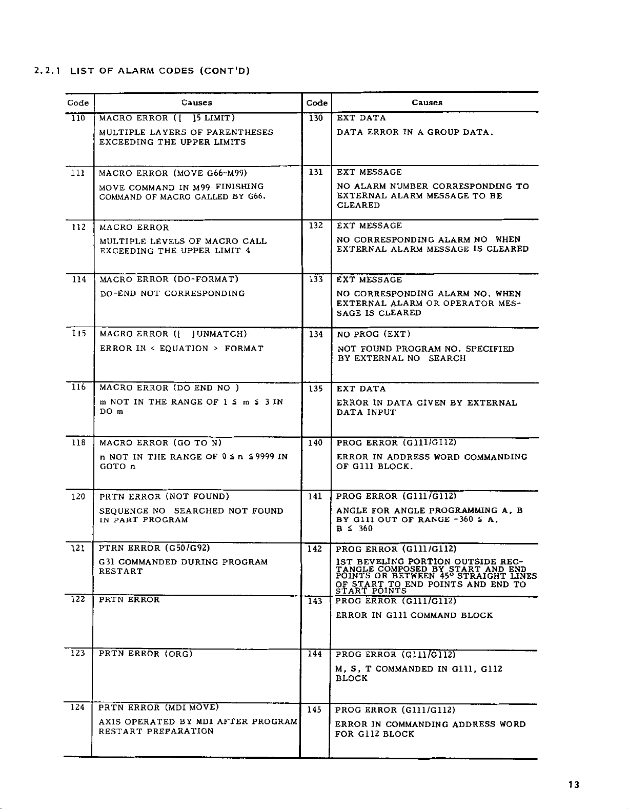
2.2.1
LIST
OF
ALARM
CODES
(CONT'D)
Code
TOOL
083
COMPENSATION
DESIGNATED
SATION
TOOL
084
TOOL
WOM,
EXTERNAL
085
MULTIPLICATION
PARAMETER
NAL
086
EXTERNAL
ERROR
EXTERNAL
087
PROG
TOUCH
REACHES
SET
090
PROG
P,
BLOCKS
TOOL
ERROR
Q
NOT
WEAR
CMP
CMP
WEAR
WEAR
COMPENSATION
GIVEN
WOP
CMP
EXCEEDING
COMPENSATION
CMP
INPUT
TOOL
ERROR
SWITCH
END
COMPENSATION
ERROR
COMMANDED
Causes
ERROR
EXCEPT
NO
AT
TOOL
ERROR
WEAR
SIMULTANEOUSLY
ERROR
FACTOR
ERROR
TURNED
ON
COMPENSATION
(G31/G35)
WHEN
ON
NOT
POINT
(G70-76/G72-78)
BY
IN
01
COMPEN¬
INPUTS
SET
FOR
11
DURING
MOTION
SKIP
OR
COMMANDS
G70,
TO
BY
EXTER¬
TOOL
71.
19
72.
73
Code
097
098
100
101
102
103
ERROR
PROG
FOUR
OR
MORE
RUPTIONS
STOCK
IN
G72
OR
PROG
DATA
R
1
ERROR
SPECIFIED
REGISTERED
CAL
ERROR
MAGNITUDE
EXCEEDING
ERROR
CAL
EXPONENT
EXCEEDING
CAL
ERROR
CALCULATION
FLOW
ERROR.
ERROR
CAL
VALUE
ROOT
Causes
(G70-76/G72-78)
PROCESSING
FINISHED
BY
REMOVAL
_
(G70-76/G72-78)
BY
IN
INTERNAL
(FIXED
OF
FIXED
UPPER
(FLOATING)
OF
FLOATING
ALLOWABLE
(DIVISION)
DIVISOR
(SQUARE
IS
A
SHAPE
CYCLE
G70,
POINT)
POINT
LIMIT
POINT
RANGE.
ZERO
ROOT)
NEGATIVE
BY
P,
KEEP
INTER¬
PROGRAM
G71,
Q
NOT
MEMORY
DATA
DATA
OR
OVER¬
v/FT.
091
092
093
094
095
096
ERROR
PROG
BLOCK
P,
Q
IN
CLUDING
PROG
ERROR(G
OF
NO
SHAPE
G71,
G70,
PROG
ERROR
UNABLE
SHAPE
G71,
G70,
PROG
ERROR
BEVELING
LAST
MOVE
SHAPE
G70,
G71
PROG
ERROR
FAULTS
SPECIFIED
ERROR
PROG
(CUTTING
D
G73
ZERO
CUTTING)
D,
KOF
RANGE
(G70-76/G72-78)
SEQUENCE
OF
G70
NOT
G70
IN
BLOCKS
PROGRAM
G72,
(G70-76/G72-78)
G-
AND
PROGRAM
G72,
(G70-76/G72-78)
AND
COMMAND
PROGRAM
,
G72,
(G
IN
FINISHED
BY
(G70-76/G72-78)
FREQUENCY)
OR
128
SPECIFIED
G76
EXCEEDING
FOUND
BLOCK
70-
76
/G
INCLUDING
SPECIFIED
G73,
AND
M-CODE
SPECIFIED
AND
G73
ROUNDING
SPECIFIED
G73
AND
70-76/G72-78)
SHAPE
Q
P,
IN
OR
MORE
BY
SPECIFIED
NO
PROG
NO.
72-78)
FINISHED
P,
BY
46
OVER
IN
FINISHED
P,
BY
COMMANDS
FINISHED
FOR
G71,
G73
PROGRAMMABLE
P,
BY
PROGRAM
G72
SPECIFIED
(ROUGH
I,
K
BOTH
IN¬
Q
Q
Q
ZERO
IN
IN
IN
BY
BY
AS
104
105
106
107
108
109
SUBSTITUTION
PROG
ERROR
CHARACTER
ED
MACRO
IN
BLOCK
A
ERROR
CONSTANTS
MACRO
TOO
MACRO
ERROR
EQUATION
MACRO
ERROR
MANY
ERROR
IN
ERROR
UNDEFINED
MACRO
PROHIBITED
ERROR
CANNOT
FOR
CANCELLING
NO
NOT
ADR)
THE
EXCEPT
#NO
LEFT)
DESIGNATED
(DOUBLE
WHICH
COMMANDINREPETITION
(CONSTANT)
EXCEEDING
CODES
(FORMAT)
THE
FORMAT
(UNDEFIN
VARIABLE
(
#NO
VARIABLE
REPEAT¬
BE
LIMIT
G67
FOR
)
DESIGNATED
AS
12
Page 15
2.2.1
LIST
OF
ALARM
CODES
(CONT'D)
Code
110
111
112
114
115
116
(
MACRO
ERROR
MULTIPLE
EXCEEDING
MACRO
MOVE
COMMANDOFMACRO
MACRO
MULTIPLE
ERROR
COMMAND
ERROR
EXCEEDING
MACRO
DO-END
MACRO
ERROR
MACRO
m
DO
NOT
m
ERROR
NOT
ERROR
IN
ERROR
IN
[
LAYERS
THE
(MOVE
IN
LEVELS
THE
(DO-FORMAT
CORRESPONDING
([
EQUATION
<
(DO
THE
RANGE
Causes
]5
OF
UPPER
M99
CALLED
OF
UPPER
UNMATCH)
]
END
LIMIT)
PARENTHESES
LIMITS
G66-M99)
FINISHING
BY
G66.
MACRO
OF
LIMIT
>
FORMAT
NO
1
£
CALL
4
)
)
m
Code
EXT
DATA
EXT
NO
DATA
ERROR
MESSAGE
ALARM
130
131
EXTERNAL
CLEARED
MESSAGE
EXT
132
CORRESPONDING
NO
EXTERNAL
133
MESSAGE
EXT
NO
CORRESPONDING
EXTERNAL
IS
SAGE
134
NO
NOT
BY
EXT
135
<
3
IN
ERROR
DATA
CLEARED
PROG
FOUND
EXTERNAL
DATA
IN
INPUT
IN
NUMBER
ALARM
ALARM
ALARM
(EXT)
PROGRAM
NO
DATA
Causes
A
GROUP
CORRESPONDING
MESSAGE
ALARM
MESSAGE
ALARM
OR
OPERATOR
NO.
SEARCH
GIVEN
BY
DATA.
BE
TO
WHEN
NO
IS
CLEARED
WHEN
NO.
SPECIFIED
EXTERNAL
TO
MES¬
118
120
121
122
123
124
MACRO
n
NOT
n
GOTO
ERROR
PRTN
SEQUENCE
IN
PART
PTRN
ERROR
G
31
COMMANDED
RESTART
ERROR
PRTN
PRTN
ERROR
ERROR
PRTN
OPERATED
AXIS
RESTART
ERROR
IN
THE
(NOT
NO
PROGRAM
(G50/G92)
(ORG)
(MDI
PREPARATION
(GO
TO
RANGE
FOUND)
SEARCHED
DURING
MOVE)
BY
MDI
N)
OF
0
PROGRAM
AFTER
n
£
NOT
£9999
IN
FOUND
PROGRAM
140
141
142
143
144
145
PROG
ERROR
Gill
OF
PROG
ANGLE
BY
Gill
360
£
B
PROG
1ST
BEVELING
TANGLE
POINTS
START
OF
START
PROG
ERROR
PROG
S,
M,
BLOCK
PROG
ERROR
G112
FOR
ERROR
ERROR
FOR
ERROR
POINTS
ERROR
IN
ERROR
T
ERROR
IN
(G111/G112)
IN
ADDRESS
BLOCK.
(G111/G112)
ANGLE
OUT
OF
(G111/G112)
COMPOSED
OR
BETWEEN
TO
(G111/G112)
Gill
(G111/G112)
COMMANDED
(G111/G112)
COMMANDING
BLOCK
WORD
PROGRAMMING
RANGE
PORTION
BY
END
POINTS
COMMAND
IN
COMMANDING
-360
OUTSIDE
START
STRAIGHT
45°
AND
BLOCK
Gill,
ADDRESS
<
A
AND
G112
,
REC¬
END
WORD
A,
END
B
LINES
TO
13
Page 16
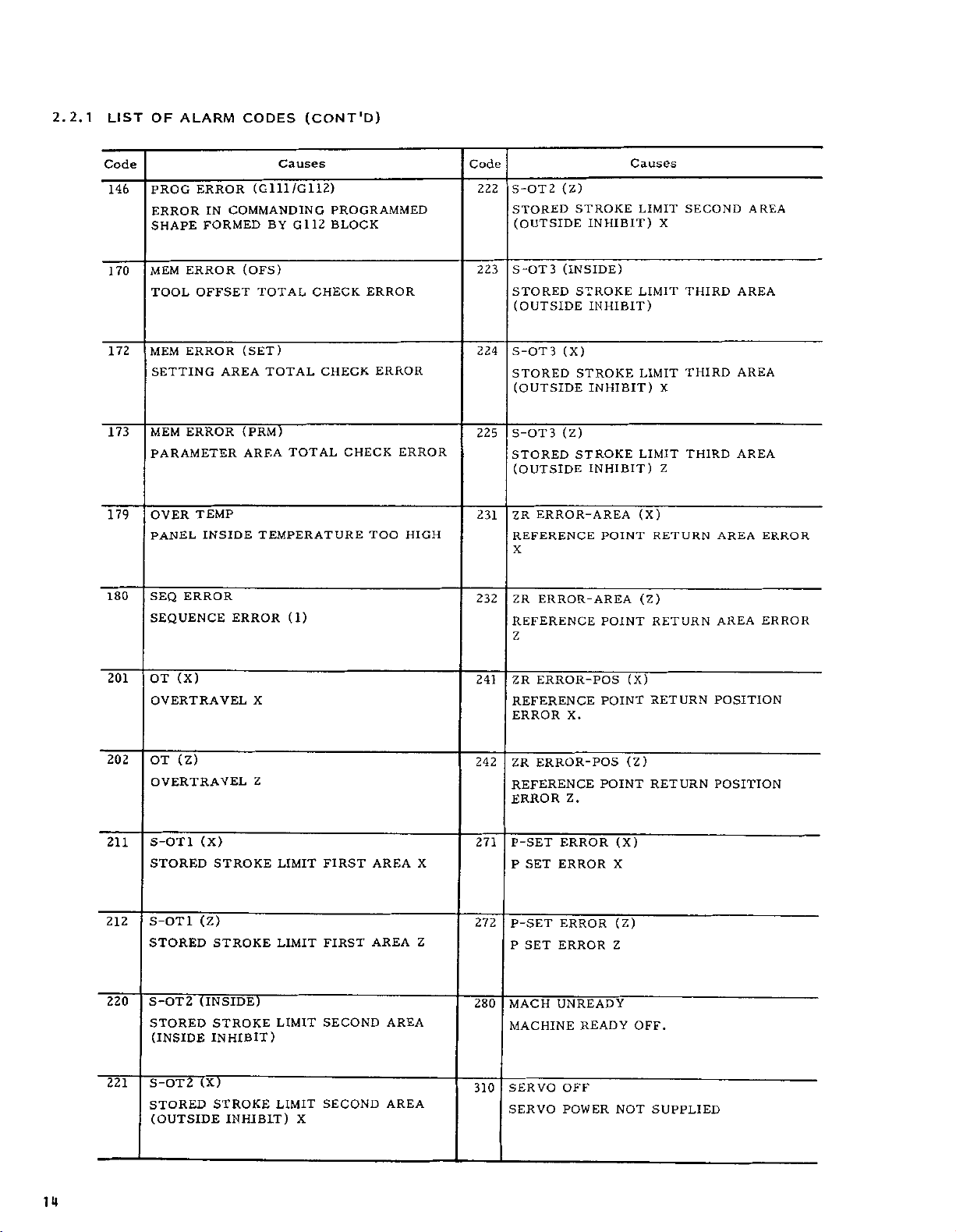
2.2.1
LIST
OF
ALARM
CODES
(CONT'D)
Code
146
170
172
173
179
180
ERROR
PROG
ERROR
SHAPE
MEM
TOOL
MEM
IN
FORMED
ERROR
OFFSET
ERROR
SETTING
ERROR
MEM
PARAMETER
TEMP
OVER
PANEL
SEQ
SEQUENCE
INSIDE
ERROR
Causes
(G111/G112)
COMMANDING
G112
BY
(OFS)
TOTAL
(SET)
TOTAL
AREA
(PRM)
TOTAL
AREA
TEMPERATURE
ERROR
(1)
PROGRAMMED
BLOCK
CHECK
ERROR
ERROR
CHECK
CHECK
TOO
ERROR
HIGH
Code
222
223
224
225
231
232
S-OT2
(Z)
STORED
(OUTSIDE
S-OT3
STORED
(OUTSIDE
S-OT3
(INSIDE)
(X)
STORED
(OUTSIDE
S-OT3
STORED
(OUTSIDE
ZR
REFERENCE
X
ZR
(Z)
ERROR-AREA
ERROR-AREA
REFERENCE
Z
STROKE
INHIBIT)
STROKE
INHIBIT)
STROKE
INHIBIT)
STROKE
INHIBIT)
POINT
POINT
Causes
LIMIT
LIMIT
LIMIT
LIMIT
(X)
RETURN
(Z)
RETURN
X
X
Z
SECOND
THIRD
THIRD
THIRD
AREA
AREA
AREA
AREA
AREA
AREA
ERROR
ERROR
201
202
211
212
220
221
(X)
OT
OVERTRAVEL
(Z)
OT
OVERTRAVEL
S-OT1
STORED
S-OT1
STORED
S-OT2
STORED
(INSIDE
S-OT2
STORED
(OUTSIDE
(X)
STROKE
(Z)
STROKE
(INSIDE)
STROKE
INHIBIT)
(X)
STROKE
X
Z
INHIBIT
LIMIT
LIMIT
LIMIT
LIMIT
)
X
FIRST
FIRST
SECOND
SECOND
AREA
AREA
AREA
AREA
POINT
POINT
(X)
X
(Z)
Z
NOT
(X)
RETURN
(Z)
RETURN
OFF.
SUPPLIED
POSITION
POSITION
ERROR-POS
ZR
241
REFERENCE
242
ERROR
ZR
X.
ERROR-POS
REFERENCE
SET
SET
Z.
ERROR
ERROR
ERROR
ERROR
UNREADY
READY
OFF
POWER
ERROR
271
P-SET
X
Z
272
280
P
P-SET
P
MACH
MACHINE
310
SERVO
SERVO
14
Page 17
2.2.1
LIST
OF
ALARM
CODES
(CONT'D)
Code
320
330
331
332
341
342
NU
UNREADY
NC
UNREADY
EMERGENCY
EMERGENCY
(X)
FUSE
FUSE
BLOWN
(Z)
FUSE
FUSE
BLOWN
SERVO
SERVO
SERVO
SERVO
ERROR
ERROR
ERROR
ERROR
P
STOP
STOP
X
Z
(X)
X
(Z)
Z
Causes
SET
UNREADY
Code
372
381
391
392
400
810
ERROR
FG
FG
ERROR
PRG
ERROR
PRG
ERROR
TG
ERROR
TG
LEAD
TG
ERROR
TG
LEAD
SEQ
ERROR
SEQUENCE
CPU
ERROR
ERROR
CPU
Causes
(2)
2
(X)
DISCONNECTION
(Z)
DISCONNECTION
ERROR
(2)
X
Z
331
352
357
361
362
371
(X)
OL
OVERLOAD
(Z)
OL
OVERLOAD
(OTHERS)
OL
OVERLOAD
ERROR
PG
PG
ERROR
PG
ERROR
ERROR
PG
FG
ERROR
ERROR
FG
(X)
X
(Z)
Z
(1)
1
(1)
(1)
(2)
CP04
CP04
ERROR,
ERROR,
MM01
MM01
RAM
ERROR
RAM
CHECK
CHECK
ERROR
ERROR,
820
X
,
ERROR
TAPE-MEM
910
Z
920
MEMORY
TAPE
TAPE
ERROR
VERIFYING
ERROR
READING-IN
ERROR
ERROR
(OFF-LINE)
(OFF-LINE)
15
Page 18
2.2.1
ALARM
LIST
"095"
OF
ALARM
CODES
(CONT'D)
Commanding
straight
ond
beveling
and
addresses
line
and
rounding.
and
X
Q
and
Z
specifying
D
specifying
sec¬
second
X-coordmates
start
ting
program
Z-coordinates
cutting
shape
Z-
mand
block
(EXCEPT
X-coordinate
mand
block
(EXCEPT
program
coordinate
different
of
difference
of
X-coordmate
G71
point
Z-coordinate
•
G72
point
start
the
FOR
the
FOR
R1
R1
diffemt
point
different
point
for
from
finished
G71
for
finished
G72
for
Command
for
command
and
and
cutting
—
cutting
from
—
finishes
finished
between
last
block
between
block
last
start
Z-coordinate
R1
program
TYPE)
shape
start
X-coordmate
R1
program.
TYPE)
shape
shape
exceeding
shape
exceeding
CUTTING
START
POINT
G71
for
finished
G72
for
point
for
point
program
cutting
program
cutting
command
command
finished
G71
by
the
by
G72
for
the
CUTTING
START
POINT
start
first
by
start
by
shape
com¬
com¬
first
cut¬
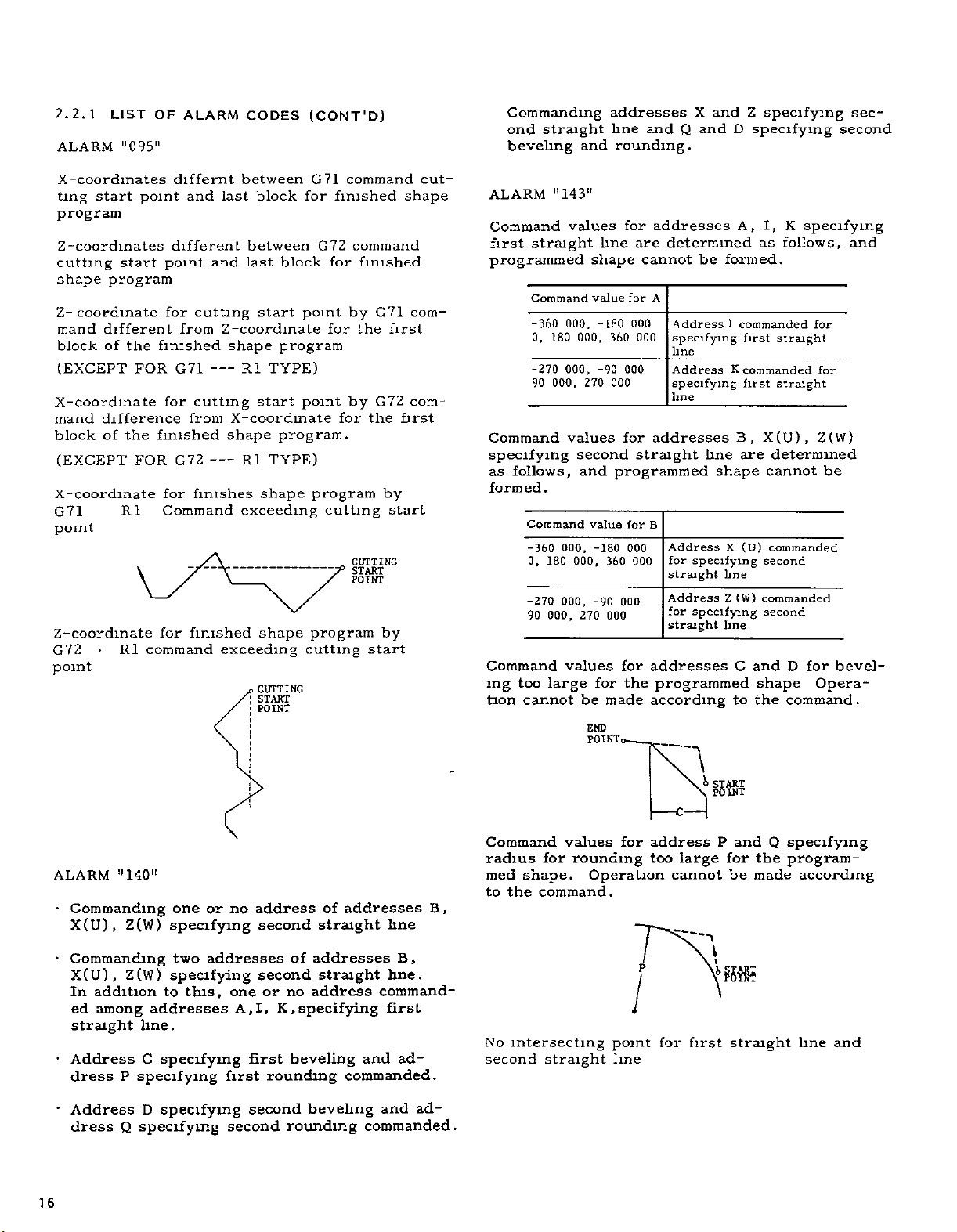
ALARM
Command
straight
first
programmed
Command
-360
0,
180
-270
90
Command
specifying
follows,
as
formed.
Command
-360
180
0.
-270
000,
90
Command
too
ing
tion
large
cannot
"143"
values
000.
000,
000,
values
second
000.
000,
000,
values
000,
270
and
270
be
line
shape
value
-180
-90
value
-180
360
-90
000
for
made
END
POINT,
360
000
for
addresses
determined
are
cannot
for
A
Address
000
000
specifying
line
000
for
Address
specifying
line
addresses
straight
programmed
for
B
Address
000
for
000
straight
Address
000
for
straight
for
addresses
the
programmed
according
’
—
be
formed.
1
K
line
shape
X
specifying
line
Z
specifying
line
C
to
i
\
!>
15®
A,
I,
follows,
as
commanded
first
straight
commanded
first
straight
X(U),
B,
are
determined
cannot
(U)
commanded
second
(W)
commanded
second
and
shape
the
K
specifying
for
for
Z(W)
be
for
D
Opera¬
command
and
bevel¬
.
ALARM
•
Commanding
X(U),
•
Commanding
X(U),Z(W)
In
ed
straight
•
Address
dress
•
Address
dress
16
"140"
Z(W)
addition
among
P
Q
one
specifying
two
specifying
this,
to
addresses
line.
C
specifying
specifying
D
specifying
specifying
or
no
addresses
one
A,
first
first
second
second
address
second
of
second
or
no
I,
K,
beveling
rounding
rounding
addresses
of
straight
addresses
straight
address
specifying
commanded.
beveling
B
line
B,
line.
command¬
first
and
ad¬
ad¬
and
commanded.
,
Command
radius
med
shape.
to
the
No
intersecting
second
values
for
rounding
Operation
command.
straight
for
point
line
address
too
P
for
large
cannot
\
first
P
for
i
\
and
the
be
made
straight
Q
specifying
program¬
according
line
and
Page 19
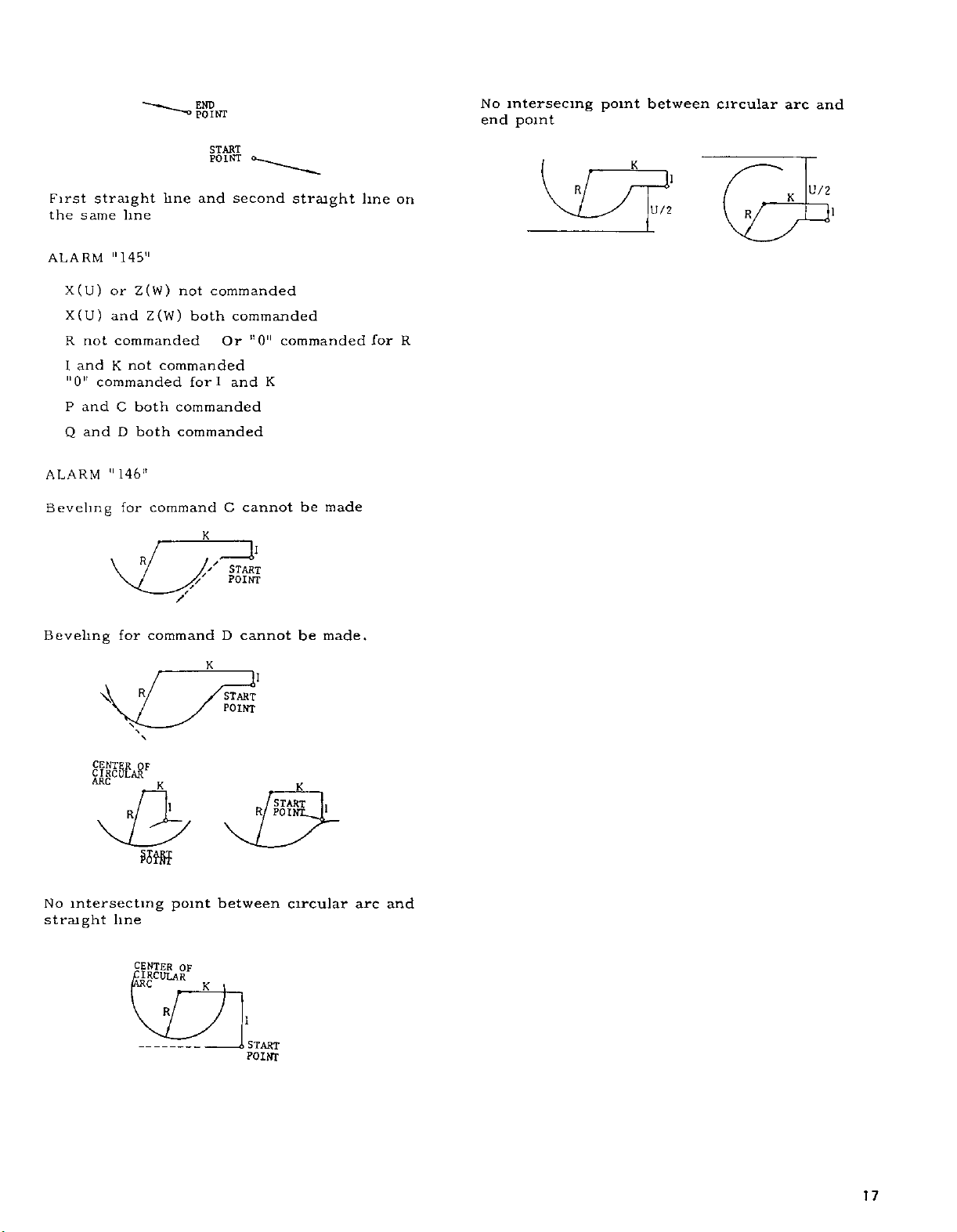
First
the
straight
same
line
line
END
POINT
START
POINT
and
second
straight
line
on
No
end
intersecing
point
between
point
K
R
1'
U/2
circular
R
arc
K
and
U/2
ALARM
X(U)
X(U)
not
R
and
I
"0"
and
P
Q
and
ALARM
Beveling
Beveling
"145"
Z(W)
or
Z{W)
and
commanded
not
K
commanded
C
both
both
D
"146"
for
command
R,
for
command
R/
A
not
commanded
both
commanded
fori
commanded
commanded
K
//'
'/
/
K
commanded
"0"
Or
K
and
cannot
C
START
POINT
cannot
D
l1
START
POINT
commanded
be
made
be
made.
for
R
No
intersecting
straight
R,
line
CENTER
£
K
1
point
OF
_
_
IRCULAR
R,
between
K
„
/
R
1
START
POINT
K
START
POINT.
circular
|1
arc
and
17
Page 20
2.2.2
COUNTERACTING
ALARMS
each
An
applies
o
o
o
EC01
RR
Error)
character
alarm
O
o
o
o
EOB
EOR
o
to
O
CN
R
L
is
o
ooo
ooo
is-
the
o
ooo
o
o
o
oo
1
GOX
BLOCK
1-
CHARACTERS
128
LESS
OR
OF
END
REWIND
oo
2
1
DATA
BLOCK
STOP
o o
oo
o
•
3
4
CODE
o
o
o
o
6
5
J
CODE
O
C
R
o
oo
o
M3
Fig.
o
o
O
o
OCE
R
2221
o
o
o
R
(
1)
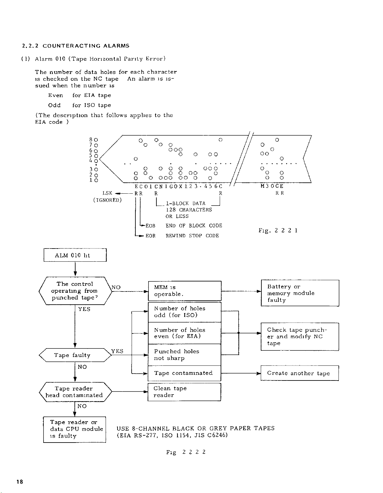
Alarm
The
is
sued
(The
EIA
010
number
checked
when
Even
Odd
description
code
(Tape
on
the
for
for
)
of
the
Horizontal
data
NC
number
EIA
ISO
that
80
7
O
§0
5
O
4
O
30
2
O
1
o
(IGNORED)
holes
tape
tape
LSK
Parity
for
tape
is
follows
ALM
The
operating
punched
Tape
Tape
head
Tape
data
is
010
i
r
control
tape7
YES
faulty
NO
reader
contaminated
NO
V
reader
CPU
faulty
lit
from
or
module
NO
YES
>
USE
8-CHANNEL
(EIA
*ÿ
RS-277,
MEM
operable
Number
(for
odd
Number
even
Punched
not
sharp
Tape
Clean
reader
ISO
is
.
of
holes
ISO)
holes
of
(for
EIA)
holes
contaminated
tape
BLACK
1154,
JIS
OR
GREY
C6246)
PAPER
Battery
*ÿ
Check
er
tape
Create
TAPES
memory
faulty
and
or
module
tape
modify
another
punch¬
NC
tape
18
Fig
2222
Page 21
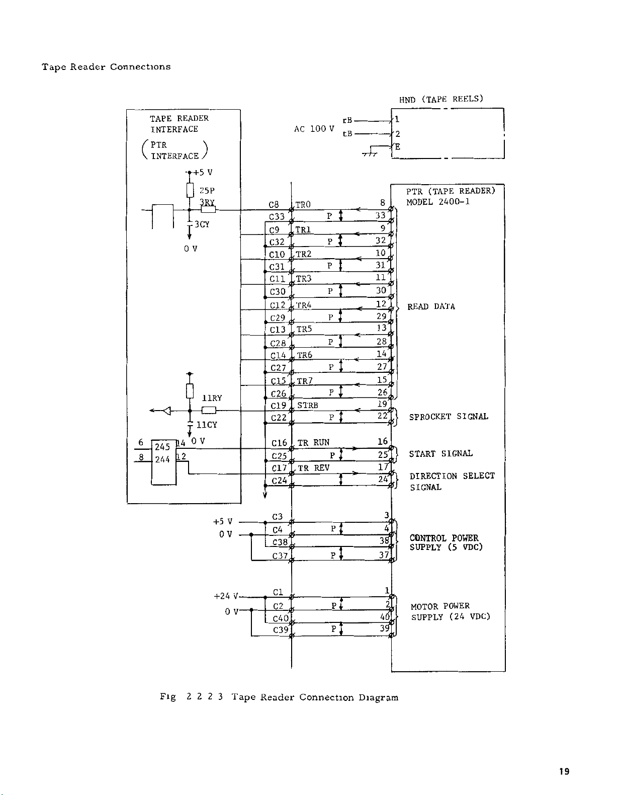
Tape
Reader
Connections
TAPE
INTERFACE
PTR
(
INTERFACE
6
245
JL_
244
READER
)
+5
25P
a
3CY
1
V
0
6
11RY
€3
11CY
x
V
0
12
(TAPE
2400-
DATA
SIGNAL
REELS)
READER)
1
SIGNAL
SELECT
(TAPE
HND
rB
V
LOO
AC
V
TRO
C8
if
C33
if
TRl
C9
it
C32
if
TR2
CIO
it
C31
if
TR3
Cll
it
C30
it
012ÿ784
TR5
C13
it
_
i
S23-f
C14;?TR6
C27
C15;fTR7
_
£26,
>
STRB
C19
it
C22
it
TR
C16
it
C25
it
TR
C17
it
C24
it
V
RUN
REV
tB
HE
Pi
p~T
P
P
p~y
P~T
P
rr"
FT"
r*
'2
PTR
MODEL
8
33
9
<
32
10
-fr
31
11
30
12
29
13
<ÿ
28
14
27
15
c-
26
19
22
16
>
-if
if
i'
READ
SPROCKET
START
P
ft
DIRECTION
SIGNAL
24
Fig
222
+5
0
+24
3
V
V
0
V
V1
Tape
C3
C4
C38
C37
Cl
C2
C40
C39
Reader
it
it
it
it
it
it
it
if
Connection
n
P
I
PT
P
3
37.
1
40
Diagram
4
b
CONTROL
SUPPLY
MOTOR
SUPPLY
POWER
POWER
(5
VDC)
(24
VDC)
19
Page 22
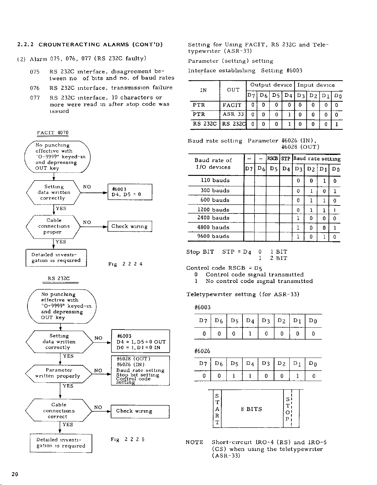
2.2.2
(2)
CROUNTERACT1NG
076,
Alarm
075
076
077
075,
RS
tween
RS
RS
more
232C
no
232C
232C
were
issued
punching
depressing
key
n
Setting
written
correctly
Cable
proper
'
is
RS
4070
with
keyed-in
YES
YES
r
investi¬
required
232C
FACIT
No
effective
"0-9999"
and
OUT
data
connections
Detailed
gation
077
interface,
bits
of
interface,
interface,
read
\
.
NO
NO
ALARMS
(RS
in
*"
-ÿ
232C
faulty)
disagreement
and
no.
transmission
characters
10
stop
after
#6003
D4,
D5
Check
Fig
2224
(CONT'D)
baud
of
code
0
=
wiring
be¬
rates
failure
or
was
Setting
typewriter
Parameter
Interface
IN
PTR
PTR
RS
Baud
Baud
I/O
110
300
600
1200
2400
4800
9600
Stop
Control
0
1
232C
rate
rate
devices
bauds
bauds
bauds
bauds
bauds
bauds
bauds
BIT
code
Control
No
for
Using
(ASR-33)
(setting)
establishing
OUT
FACIT
ASR
RS
setting
of
STP
RSCB
control
33
232C
code
=
code
FACIT,
D?
D4
RS
setting
Setting
Output
D7
0
0
0 0
Parameter
-
D5
signal
device
D5
D6
0 0 0 0 0
0
0
0 0
RSCB
D
D5
6
0
BIT
1
BIT
1
2
transmitted
signal
transmitted
232C
#6003
D4
1
1
#6026
#6028
STP
D4
and
Input
D3
0 0
Baud
D3
0
0
0
0
1
1
1
D2
(IN),
(OUT)
rate
D2
0
1
1
1
0
0
0
Tele¬
device
0
Dl
0
0 0
0
setting
Dl
1
0
1
1
0
0
1
DO
0
1
DO
0
1
0
1
0
1
0
No
effective
"0-9999"
and
OUT
data
correctly
Parameter
written
connections
Detailed
gation
punching
depressing
key
Setting
written
I
properly
Cable
correct
investi¬
is
with
keyed-in
YES
YES
YES
required
(for
'
Teletypewriter
setting
ASR-33)
#6003
,
-ÿ
#6003
D4
DO
#6028
#6026
Baud
Stop
Control
setting
Check
Fig
2
=
=
1,
1.D1
(OUT)
(IN)
rate
bit
wiring
2 2
D5
setting
code
_
5
0
=
=0
setting
OUT
IN
NO
NO
NO
#6026
NOTE
D?
0
D7
0 0
Short-circuit
D6
0
D6
S
T
A
R
T
(CS)
when
(ASR-33)
D5
0
D5
1
8
D4
1
D4
1
BITS
using
D3
0
D
0
1RO-4
D2
0
D
3
2
0
(RS)
the
teletypewriter
DO
Dl
0
0
D0
Dl
0
1
S
T
O
P
1RO-5
and
20
Page 23

Signals
Timing
I
P
DATE
READY
and
Connection
100
\As
OS
100
MIN
MIN
Diagram
18MS
8MS
1
for
MAX
i
i
—
i
i
MAX
1
J
FACIT
4070
PUNCH
FACIT
100
\is
connection
i
pTp
i
INTER¬
FACE
I
\
10
MS
diagram
Dl
D50
D2
D49
D3
D48
D4
D47
D5
D44
D46
i
D6
D7
D8
10
Fig
4
4*
4
41
4L
9-
4*-
if~
9-
MS
TAPE
2.2
MS
10
10
MS
2
6
Timing
20
CHI
CH2
CH3
CH4
CH5
CH6
CH7
CH8
CH9
5D
PI
PR
TL
ERR
DATA
SIGNALS
PUNCH
READY
-o
if
4*if-
-if-
ifif-
if-
0ÿ
if
V-
MR-
P
12
13
14
15
16
17
18
19
9
1
3
5
f,2
1
5
6
10
11
12
3
4
7
8
9
21
20
24
PTP
FACIT
4070
i
Fig
D43
+
4
222
7
OF
FACIT
I
Connection
if-
10
8
Diagram
25
21
Page 24

2.2.2
COUNTERACTING
ALARMS
JANCD-CP03
DNC
Interface
CHI
(
for
RS232C)
V
V
V
-12
24
V
•
L
0
V
(CONT'D)
D39
TTY
D38
TTY
SD
1
D
2
if-
3
D
RD
1
RS
D
1
4
-b-
D15
CS
-fh
D16
DR
fh
D17
ER
fh
34
D
D33
Dll
D40
DIO
9
D
D4I
42
D
1
2
7W7
0
P
PO-6
1RO-2
1RO-3
1RO-4
IRO-5
1R0-6
IRO-20
1R0-7
7
TELETYPEWRITER
OUT
Jj
SEND
RECEIVE
#
-b
SEND
-b
SEND
-M
DATA
DATA
-b
READY
SIGNAL
FRAME
"f
DATA
DATA
REQUEST
ENABLE
SET
READY
TERMINATION
GROUND
GROUND
RS
SD
CS
RD
,
-2
CHARACTERS
—
1_
OR
LESS
(3)
a.
b.
c.
Alarm
No
170
172
173
Alarms
170
172
173
These
setting
changed
Battery
Memory
Failure
MEMORY
(OFS)
MEMORY
(SET)
MEMORY
(PRM)
170,
MEM
MEM
MEM
alarms
data,
unit
modules
of
CRT
172,
error
error
error
due
memory
Display
(OFS),
(SET),
(PRM)
warn
and
to
any
failure
(2)
ERROR
ERROR
ERROR
Fig
Error)
(MEM
173
tool
error
setting
check
,
parameter
check
tool
that
parameter
the
of
following
(Battery
not
connected
module
(1)
Location
Memory
MM02-
XX XX
,
20C
20D
,
19D
19C
18D
,
18C
,
17D
17C
2228
offset
error
error
offset
have
alarm
or
area
area
amount,
been
correctly
(2).
Module
MM05
ID
1C
RS
total
total
reasons
display)
on
MM01C-
check
total
3M
3L
232C
Connection
(4)
Alarm
This
temperature
two
perature
control
is
i
NOTE
The
mostat
When
pins
Diagram
179
alarm
possible
panel
stopped
JANCDTU02
C16
C8
customer
(contacts
the
system
C8
and
A13
A7
(Panel
is
C16
activated
is
is
causes,
high,
or
Check
Fig
(OEM)
Inside
45°C
or
the
JANCD-
CP03
M13
*
TH2
’
M7
usually
not
is
TU02,
at
or
external
for
I
+24
2229
can
Temperature
when
higher
either
the
cooling
both
IÿQgRY
101RY
7K
4
V
add
closed)
use,
m
as
the
There
the
ambient
fan
ventilation
TH1
I
52CY
T
0
V
another
short-circuit
illustrated
panel
Tool
inside
ther¬
High)
inside
are
tem¬
the
fan
22
Page 25

(5)
Alarms
Error)
231
(X),
232
(Z)
(Zero
Reutnr
Area
(6)
shown
As
ence
and
alarms
power
Alarms
Return
zero
reference
cannot
is
applied.
241
Area
below
point
return
zero
be
DECLS
(DECELERATION
LIMIT
REFERENCE
POINT
(X),
Errors)
an
point
issued
SWITCH)
SIGNAL
242
alarm
is
RAPID
JOG
(Z)
results
made
Notice
on
a
(Reference
between
first
I
when
that
run
these
after
Point
refer¬
DECLS
0
Fig
1
2
fl
2
REFERENCE
POINT
ZERO
H-OT
S-OT
210
11
2.
PG
200
PULSES
This
type
ence
point
automatically
the
previous
NOTE
No
This
switch
of
return
is
alarm
(G27
reference
check
to
set
Alarm
‘
Reference
return
point
ally
PG
I
forms
See
2
\
Servo
module
results
performed
G28)
or
point
made
is
"0
"
24Q
lit
JL
manu¬
made
YES
wave-
proper
Fig
2
11
2
CPU
faulty
\
\
/
/
when
is
when
NO
the
manually
different
the
NO
refer¬
or
from
system
/
point
matically
\
Reference
return
or
Operation
with
proper
Reference
return
after
turning
power
auto-
by
made
G
28
NO
GOO
YES
u
point
incomplete
PHASE
PHASE
PHASE
G27
NO
on
A
B
c
YES
(REFERENCE
Fig.
Check
address
Feedback
faulty
90°
X-
values
POINT
2
2
and
unit
Fig
PULSE)
2
Z-axi®
is
2
11
2.2
12
'l
PG
is
faulty
23
Page 26

2.2.2
COUNTERACTING
(CONT'D)
ALARM
CODES
(7)
Alarms
This
between
value
ter)
Alarm
Operations
by
EP
stop
at
than
271
type
current
is
after
27
I
handle
OK
count
more
32
NO
(X),
272
error
of
position
32
pulses
positioning
POSITIONING
BLOCK
(ÿ)
NO
YES
(Z)
results
below
or
according
(PSET
value
-ÿ
when
(set
zero
Error)
a
and
by
to
1
Servo
error
ing
pulses
Servo
adjustment
available
difference
command
parame¬
command
OUTSIDE
PULSES
32
J
occur-
at
8192
NO
NO
OF
YES
YES
Display
COMMAND
POSITION
•
on
Parameter
#6056
#6057
#6058
/
load
\
Make
zero
ment.
Motor
sive
adjust¬
-ÿ(
the
n32"
"32"
"32"
exces-
NO
another
CRT
100
X
X
Less
100
settings
33
X-axis
Y-axis
Z-axis
YES
is
than
or
968
99
or
more
>ÿ
Check
machine
tool
Refer
(12)
on
to
3
page
1
54.
(8)
Investigate
Alarm
alarm
This
unready)
of
sion
the
if
MS2
-o
o-
Fig
W
(Machine
280
results
signal
NC
the
signal
MRD
(OIL
PRESSURE)
2 2 2
14
Measure
*
(1
Unready)
from
being
Ready
normal.
is
03-9
.03-14
1
V
+24
Connection
pulse
the
OFF
Signal
1001
24V
4.7K
MRD
after
33K
C3
Example
V
D
A
output
I
faulty
(FANCD-CP02)
the
D/A
(machine
transmis¬
Check
3.5V
41
mV)
C
=1.22
41RI
I
voltage
.
to
see
*.
on
an
SEQUENCE
ALARM
initial
NC
READY
MRD
ON
OFF
Fig
Fig.
power
2
2
2
application
15
2
2
2
13
Sequence
TURNED
RESET
n
OFF
BY
SWITCH.
24
Page 27

(9)
Alarm
This
to
a
depressed
is
limit
330
alarm
stop
switch
(Emergency
displayed
is
the
when
is
or
turned
when
Stop)
and
emergency
machine
the
on
the
system
stop
comes
pushbutton
stroke
end
(10)
Alarms
(Servo
These
transistor(s)
YASNAC
331
Fuse
errors
service
(X),
Blown)
are
.
(Z)
322
attributable
Immediately
personell
to
contact
damaged
the
(
11)
Alarms
(Servo
Alarm
341
Error)
34
r
'
(X)
lit
0
Heavy¬
load
machining
m
progress
NO
-*ÿ
'
'
Alarm
displayed
reduced
at
feed-
rate
,
342
YES
NO
(Z
-ÿ
)
alarm
No
in
operation
Motor
alone
no-load
.
NO
OK
NO
YES
YES
Machining
dition
taxing
Load
for
is
.
is
motor
too
too
capacity
con¬
heavy
Change
condition.
ing
Consult
chine
machin¬
the
tool
ma-,
builder
YES
ir
Motor
free
defects.
of
NO
Worn-out
Roughened
surface
1
\
brush
commutator
Replace
or
*-
commutator
brush
repair
.
output
Servo
module
faulty.
D/A
U
YES
sent
NO
CPU
is
YES
Servopack
faulty
Typical
is
parameter
(servo
/
7
Fig.
error
2.2.2.16
setting
area)
#6074
#6075
An
alarm
portion
left-hand
16:
X-axis
16-
Z-axis
is
(follow-up
figure
issued
when
deviation)
exceeds
the
8192
shaded
m
pulses
the
25
Page 28

2.2.2
(12)
Alarms
These
machining
COUNTERACTING
(X),
351
1)
(
(Overload
Electronic
alarms
condition
indicate
)
thermal
or
ALARMS
(Z
352
relay
overload.
machine
)
(CONT'D)
trip
Check
tool
load
the
(13)
This
ative
are
more
unit
Alarm
alarm
resistance
high
of
and
357
initiated
is
motor
rating)
the
servomotor
(Overload
by
temperature.
operation
,
failures
(2))
too
high
Main
frequency
of
servo
regener¬
causes
(100%
drive
or
(14)
Alarms
The
possible
given
Servopack
to
361
the
(X).
cause
servo
TGON
JUSP-DCP
(Z
362
is
CPU
signal
)
that
A
2
C
(PG
no
module
being
*
error)
PG
turned
input
despite
JANCD-
TU02
C7
C15
Fig.
is
the
on.
JANCD-CP03
V
+24
107RY
7K
4
8
A
9
A
2
4
—
2
2
18
PHASE
106RY
33K
A.
0
•
PG
90°
K
55CY
1
V
V
Waveforms
OUT
OF
*
PHASE
(type
ZC7)
T
APPROX
t
V
8
26
Alarm
input
given
Wiring
correct
Feedback
is
faulty
PG
36
NO
YES
Q
unit
ht
B-
PHASE
2
2
Waveforms
PHASE
.
2.2.2
2.20
J
21
(type
i
1
ZD7)
1
3
J
~L
r
V
5
Fig
YES
NO
Servo
is
Correct
*
2.2.2.19
faulty
CPU
wiring
module
PHASE
A
PRASE
B
Fig
PG
’
OUT
90°
t*
A-
B
OF
i
1
!
i
I
i
t
f
i
Fig
Page 29

(15)
Alarms
391
(X),
392
(Y)
(TG
error)
(Z)
,
393
MR-K
The
or
when
r
A
on
pulse
alarm
Alarm
Motor
speed
high
Motor
and
connected
Wiring
+
of
TG
wired
output
unit
is
A
and
3
9
1
I
too
NO
terms
B
properly
YES
I
and
correct
YES
A-B
correctly
on
YES
D/A
of
proper
YES
PG
I
NC
lit
PG
when
B
on
lit
YES
N
NO
NO
-
NO
NO
the
and/or
motor
TG
are
Check
the
Does
motor
Is
the
TG
rotation
If
the
terms
motor
terms
unit
the
If
rotation
motor
terms
terms
B
the
rotation
If
connecting
motor
Jll,
respectively
the
rotation
If
motor
connecting
J10,
respectively
the
If
rotation
connecting
If
the
rotation
connect
respectively
On
a
first
On
a
second
for
verification
is
wired
TG
wiring
A
and
motor
power
wired
in
voltage
speed
correct7
clockwise
is
and
A
B
and
counterclockwise
is
and
A
A,
respectively
is
clockwise
pins
counterclockwise
is
pins
clockwise
is
A
pins
is
counterclockwise
connecting
application,
power
to
in
reverse,
exceed
B
should
,
respectively
should
B
L(G)
L(G)
B
and
application,
check
reverse
the
viewed
be
be
viewed
and
and
viewed
to
PG
pins
D/A
the
rating7
connected
connected
M(H)
M(H)
pins
A
check
use
disconnected,
or
from
viewed
from
to
viewed
to
from
J16
viewed
B
and
the
(error
EP
output
drive
drive
TG
TG
drive
and
to
D/A
to
from
to
from
from
PG
end,
servo
drive
servo
end,
pins
drive
pins
end,
J18,
drive
pins
output
pulse)
end,
unit
connect
J10
and
end
Jll
and
connect
respectively
end,
JI8
and
,
connect
motor
J16,
(16)
(17)
Alarm
This
Alarm
(T)
#
RAM
RAM
No
#98
#99
#100
#101
#102
#103
#104-
RAM
Memory
Module
Type
810
alarm
820
check
No.
01C
01C
01B
01C
01B
01C
01B
01C
01B
01C
01B
01C
Investigate
unit
(CPU
is
820
and
Location
on
Board
MM
motor
or
error)
displayed
error
No
RAM
Location
Module
2E
2C
13D
2F
13C
2D
12D
3E
12C
3C
1
ID
3F
servo
RAM
No
#105
#106
#107
#108
#109
#110
when
Memory
Module
Type
01B
01C
01B
01C
01B
01C
01B
01C
01B
01C
01B
01C
a
MM
CPU
Location
on
Board
malfunction
Module
11C
3D
10D
4E
10C
4C
9D
4F
9C
4D
8D
5E
RAM
No
#111
#112
#113
#500
#501
prevents
Memory
Module
Type
01B
01C
01B
01C
01B
01C
(CP02)
(CP02)
MM
the
Location
on
Module
Board
8C
5c
7D
5F
7C
5D
Z7C
27A
operation.
(D
©
#
CP02
MM01
Fig.
error
a
error
i
i
2.2.2.22
820
Normal
Abnormal
P-ROM
820
Normal
Abnormal
P-ROM
total
No
total
No
total
total
value
value
(80-85)
value
value
(00-37)
27
Page 30

TROUBLESHOOTING
3
2
WITHOUT
ALARM
CODES
The
following
correcting
which
1)
(
Power
basic
flow
troubles
operations
cannot
First
application
impossible
Neon
composite
supply
LED
power
charts
be
power
lamp
unit
input
lit.
not
applied
power
YES
of
shown
are
of
lit
unit
the
are
abnormal
N
instructions
by
NO
NO
alarm
codes,
applied
Input
NC
for
in
unit.
power
to
YES
the
NO
Connect
to
the
Composite
fuse
blown
Power
blown
input
system
input
out.
power
out
unit
power
supply
YES
push¬
/OFF
Power
off
seconds
turned
about
later.
3
NO
Power
buttons
operable.
Package
YES
supply
short-circuited
load
from
composite
unit.
Fig
3.1
2
No
1
output
power
+5
2
V
CP03
ON
are
Type
failure
not
JANCD-
freely
28
Page 31

TROUBLESHOOTING
2.3
(CONT'D)
WITHOUT
ALARM
CODES
(2)
HANDLE
MODE
Handle
operation
HANDLE
MODE
selected
Axis
selection
magnification
desired
Handle
generated
pulses
Handle
CPU
module
faulty
Continued
operation
mode
YES
YES
YES
or
PG
to
faulty
and
*
data
is
©
is
faulty
A
DGN
1300
D7
D6
D5
D3
D4
*
DGN
//I
301
D7
D6
,-1-
+
1“
t
These
*
Displayed
NOTE
HP
1
//I
DGN
D7
D6
H
H
Z
X
DGN
//
1
D7
D6
HIHIHI HI
HI
P7
P6
Set
1=75
as
D3
302
D5
282
D5
P5
checks
D3
D4
D3
D4
D4D3D2
P4
P3
should
right
at
correctly
mm
D2
H
D2
D2
Hi
P2
/min
D1
D1
D1
HP HP
4
D1
HI
PI
side
the
DO
DO
DO
2
DO
HI
P0
made
be
of
parameter
)
L
each
across
minals
handle
generated
terminals
handle
input
nector
Data
is
faulty
displaying
by
check
+
12
1
P
ul
Pulses
to
of
module
CPU
item
#6222
V
ter¬
and
PG
YES
ses
from
and
3
PG
YES
con¬
F
data
YES
module
is
(maximum
2
CPU
I/O
5
the
of
'
of
,
signals
correct
.NO
NO
.NO
manual
Check
Handle
faulty
Check
cables
signal
handle
power
Check
connectors
PG
wiring
states
feedrate,
for
supply
shorted
is
and
Handle
PAH
PBH
PG
Connection
90°
OF
PGH
OUT
PHASE
h-
Diagram
3
/
4
5,
6,
1,
2,
T
8
i
2
2.3
Fig.
MODULE
CPU
DATA
(
JANCD-CP03)
F16
F17
F9
,,_F18
F19
F12
F4
FI
-ff-
F5
-ff-
F2
if-
F6
-((-
HANDLE
PG
INTERFACE
T
P
V
*
P
*
!
}
i
I
(PHASE
(PHASE
PAH
SIGNAL)
OAH
PBH
SIGNAL)
OBH
V
+12
V
0
A
B
F3
0G
V
U
SHORTED
—
12
(
3
PI
P16
P2
---**ÿ
CONNECTORS
V
HANDLE
V
HANDLE
PG*
PG:
P1-P16
P2-P15
V
+12
V
+5
CONNECTED
CONNECTED
2
Fig
)
3.3
29
Page 32

TROUBLESHOOTING
2.3
(CONT'D)
WITHOUT
ALARM
CODES
(3)
Manual
Jog
faulty
<
setting
jog
mode
pushbutton
depressed
mode
feedrate
input
Parameter
mode
operation
Jog
YES
i
Jog
selected
YES
u
Jog
.
NO
V_
correct
NO
operation
*
*
faulty
#1302
DGN
D7
D6
DGN
D6
D7
*
DGN
D7
D6
D5
-Z
#1300
D5
#1
301
D5
D4
D3
+Z
-x
D3
D4
D4
JV16
#6233
\
#6264
D2
+x
D2
D3
JV8
Jog
Jog
D1
D1
J
D2
JV4
feedrate
feedrate
DO
DO
JV2
D1
DO
JV1
step
step
0
31
NOTE
the
m
NOTE
no
if
feedrate
is
given.
"l"
("1"
No
automatic
No
feedrate
exceeding
=1
=0
operation
operation
is
mm
/min
in
1
operation
given
the
/mm)
is
is
or
rating
made
mode
executed
the
30
Detailed
is
required
ir
investigation
These
*
Displayed
checks
at
should
right
side
be
made
of
each
by
displaying
check
item
Fig
4
2.3
signals
I/O
correct
the
is
signal
states
Page 33

(4)
Manual
Rapid
faulty
mode
rapid
mode
Jog
pushbutton
depressed
YES
Rapid
selected
mode
operation
YES
operation
*
*
faulty
DGN
D7
DGN
D7
#1302
D6
#1300
D6
D5
-Z
D5
D4
+Z
D4
D3
-X
D3
D2
+X
D2
D1
D1
DO
DO
RX
Override
input
Parameter
setting
Detailed
tion
is
entered
NO
1
>
correct
NO
J
investiga¬
required
*
*
These
Displayed
checks
#1301
DGN
D7
D6
ROV
2
D5
ROV
1
D4
D3
D2
D1
DO
ROV1
ROV
2
PEM
0
0
25%
1
0
50%
0
1
100%
1
1
L
t
be
made
of
X
Z
X
Z
Fig.
each
Rapid
Rapid
Rapid
2.3.5
by
displaying
check
feedrate
acceleration
override
I/O
item
the
is
1=7.5
(0.75
/deceleration
rate
FQ
signals
correct
mm
/min
mch/min)
signal
1
=
status.
125/8
mm
/secÿ
#6280
#6282
#6286
#6288
#6231
should
right
side
at
31
Page 34

TROUBLESHOOTING
2.3
(CONT'D)
WITHOUT
ALARM
CODES
(5)
Manual
(0
.
Detailed
tion
Overtravel
results
deceleration
return
selected
Deceler-
ation
of
1
Parameter
setting
is
reference
without
YES
Zero
mode
YES
LS
in
to
0
YES
correct
YES
investiga¬
required
order
to
*
l.*y
zero
'
return
operation
DGN
D6
D7
ZRN
DGN
D7
D6
#6310
#6311
#6316
,#6317
#1304
D5
#1306
D5
*DCZ
X
Z
n
faulty
D4
D3
D4
*DCX
Approach
point
Approach
point
D2
D3
D1
D2
return
return
DO
Dt
speed
speed
DO
1
2
for
for
reference
reference
Fig.
2.3
1
75
mm/min
=
(0.75
inch
/min)
6
In)
Deceleration
sults
m
reference
point
generated.
Feedback
is
faulty
re¬
overtravel
V
No
pulse
YES
unit
These
*
Displayed
NO
checks
CP02
package
faulty
is
3.7
2
Fig
signals
should
at
right
side
be
made
of
each
by
displaying
check
item
I/O
correct
the
is
signal
status
32
Page 35

(6)
Cycle
start
sp*
inputted
No
Detailed
tion
failure
stai
ST
STLK
signal
absent
System
switch
to
required
is
t
failure
and
signals
YES
YES
ti
"0
YES
investiga¬
)
01
DGN
304
D7
D6
*
DGN
01303
D7
D6
*
//1
DGN
D6
set
D7
D5
D3
ST
LK
280
D3
D4
D4
D4
D3
D3
D3
*
checks
These
*
Displayed
signal
at
status
D2
D2
D2
right
Fig
D1
*
SP
DO
D1
DO
D1
should
ST
0
DO
side
ii
ii
u
»i
n
I
each
II
j
”0"
NG
NG
by
check
”r
to
displaying
item
T,on
to
I/O
signals
correct
the
is
Sl>*
ST
made
be
of
2
3
8
(7)
No
operation
operation
able
.
input
Detailed
tion
available
No
with
G01,
or
G03
1
i
Distribution
in
progress
YES
Override
given
YES
1
'
Dry
input
pre¬
sent
NO
r
’
investiga¬
is
required
avail¬
*
G02
*
with
G01,
DGN
D7
DGN
D7
+
These
Displayed
G02orG03
NOTE
01301
D6
D5
D4
FV
16
//I
303
D6
D5
D4
DRN
checks
at
The
screen
D3
FV
8
D3
should
right
character
during
D2
D1
FV
FV
4
2
D2
D1
side
Fig.
be
DO
FV
1
DO
made
of
2
"F"
distribution
by
each
3.9
blinks
displaying
check
at
bottom
NOTE
I/O
itemisthe
of
Check
ride
or
signals
correct
the
is
higher
to
set
CRT
see
signal
if
the
over¬
0%,
at
200%
or
status
33
Page 36

TROUBLESHOOTING
2.3
(CONT'D)
WITHOUT
ALARM
CODES
(8)
Spindle
Connection
does
not
Spindle
not
command
given
check
at
Diagram
rotate
rotate
Speed
to
drive
Voltage
terminal
4B
does
voltage
spindle
NO
NO
for
YES
YES
Spindle
<
\
16
SPk'KlT
Check
drive
output
(sequencer)
Data
defective
4B
1
o
E7
spindle
unit
SPENO
present
YES
CPU
DAS
7*
module
NO
Fig
2
Check
on
3
10
interlock
machine
tool
signal
side
SPINDLE
D/A
OUTPUT
SG
MODULE
CPU
DATA
(JANCD-CP01)
SPINDLE
BINARY
OUTPUT
12BIT
SPEN1
O
E12
E19
E6
E13
OG_E20
E2
E
3
E4
E5
E8
E9
E10,
E14
E15
E16
E17
It?*
E
I
OV
-<
-if
EN1
>
SGS1
ENO
SGSO
R1
R2
R3
R4
R5
R6
R7
R8
R9
RIO
Rll
R12
OR
SPINDLE
SPEED
±E
I
ON
>
COMMAND
WITH
Fig
"1"
3
2
SIGNAL
11
34
Page 37

(9)
CRT
screen
Connection
display
Diagram
faulty
for
CRT
V
H
SYNC
SYNC
(ÿ62.
5ps
16
5ms
JANCD-CP01
CRT
CONTROLLER
VIDEO
VIDEO
*
HLGHT
*HLGHT
SYNC
H
SYNC
*H
SYNC
V
SYNC
*V
+12
012
1*
.42
t
i
1
i
Fig.
B1
B9
L-
1CN2
1CN5
Hill
HIM
JANCD-SP01
CRT
1VR*
BRIGHTNESS
2VR
CONTRAST
12
3
2
Hill
INTERFACE
1VR
e
I
V
0
D17
DIO
4
D
D5
D6
Dlljr
D18
D13
it
VIDEO
OV
if
HSYNC
,
VSYNC
it
jP20f
D
B
c
j
L
if
F
H
7>*'
CRT
i
VIDEO
J1
J2
J8
J9
J14
-it-
-it-
-if-
i*
i
J15
J16
0
J17
it
7TB
V
012
V
it
35
Page 38

TROUBLESHOOTING
2.3
(CONT'D)
WITHOUT
ALARM
CODES
(1)
Description
SYNC
H
A.
.
;
.
B
TTV'WT-
-,‘C
In
;
>
With
,J
/
V\
u*i
of
VIDEO
and
normal
.<>1
-
U
-
no
VIDEO
1
.
I
-Vr
*
svnwc-.
'ÿ
:‘V
•'
»«*•
Hi
»»ÿ*»
.
CRT
Signals
signals
state
,
•
—
&s/ÿ[5£l«e
-
Fig
2.3.13
signal
:
«
VU5I33-
n
•
Ml
IBM
PUIE
T-T"
!
'I
i
Ml
*1
"
*ÿ
»
:
'
A"
1
—
'
•
Use
In
.
H
*
•
<
2-channel
a
the
left-hand
SYNC
With
is
The
and
Check
across
signal
If
H
The
H
Either
tive
VIDEO
signal
VIDEO
in
proportion
screen
brightest
the
CRT
2
synchronization
SYNC
screen
SYNC
JANCD-
As
signal
changed
screen
the
on
signal
by
signal
signal
shown
even
oscilloscope
figure,
and
signal
to
least
is
PRM
m
1
connectors
measuring
triggered
appears
comes
CP03
m
drops
if
the
2
the
,
2
the
number
bright
and
by
not
is
as
shown
in
JANCD-SP01
or
the
left-hand
level
in
characters
1
represents
VIDEO
the
in
DGN
measuring
and
L
L
obtained,
screen
the
and
left
and
signal
of
characters
alarm
modes
F
J
when
figure,
remains
are
the
brightness
mode.
the
voltage
Check
have
the
no
defec¬
is
the
un-
changed
the
36
C.
With
•*ÿ!*>
HH
no
H
»
—
Fig.
SYNC
luoirtoi
v
Fig.
2.
3.14
signal
2.3.15
*
The
SYNC
H
The
visible
screen
screen
even
appears
signal
disappears,
with
comes
the
as
in.
Bright
shown
and
!
left
the
Control
when
mask
is
turned
no
not
on
Page 39

(2)
V
SYNC
A
In
normal
'
IP*
F
:
and
VIDEO
state
signals
C
With
The
cally.
in
•
If
nals
appear,
•
If
and/or
or
no
characters
The
Fig
the
are
the
replace
V
SYNC
waveforms
2
3
5
SYNC,
H
normal
the
waveforms
VIDEO
JANCD-CP01
on
CRT
signal
the
V
and
unit
of
signal
screen
are
SYNC
the
the
are
shift
the
same
and
screen
is
defective.
SYNC,
H
abnormal,
or
NANCD-SP01.
VIDEO
fails
verti¬
as
V
check
shown
sig¬
to
SYNC
Use
a
2-channel
1
ft
ggift,
L*]
oscilloscope.
Fig.
SUPPLY
2
4
2.4.1
CHECK
c
a
a
©
©
VOLTAGE
POWER
16CN
i
o
1LED
CC
©
JANCD-TU02
Bi
®
SN
CHECK
SUPPLY
CN
18
a
K
CV
VOLTAGE
o
CA
©
03
°
©
©
iFu
2Fu
©
13CN
14CN
2
3.16
15CN
n
17CN
©
4RL
©
SVM
In
the
SYNC
V
)
K
nectors
With
as
the
mode
in
not
NOTE
V
B
.
left-hand
and
the
bright
scanning
the
detected
SYNC
With
The
the
screen
ble
signal
2
L
with
ALM
With
no
above
V
by
(across
the
and
VIDEO
viewed
as
lines
PRM
mode
no
signal
VIDEO
VIDEO
SYNC
disappears
operation
figure,
VIDEO
)
J
signal,
and
when
synchronization,
1
CRT
signal
the
crosswise.
most
are
DGN
corresponding
triggered
signal
waveforms
remains,
alone
But
of
the
represents
connectors
(across
CRT
screen
As
dense
A
Only
disappear,
and
mask
the
Bright
the
CRT
shown
the
in
and
alarm
have
the
is
Control.
L
appears
POS
sppear
B
the
CRT
visi¬
and
con-
left,
©
is
©
©
AMX
©
©
BMX
©
© ©
AMZ
EMX
0
0
BMZ
©
© ©
0
EMZ
©
0
S
©
©
R
0
0
r
©
0
0 0
S
T
©
©
©
C
©
200/220/230,
+10%to-15%
50/60
Hz
37
Page 40

2.4.2
DC
POWER
SUPPLY
VOLTAGE
CHECK
NEON
It
tube
Input
200/220
will
lamp
be
fuses
Power
VAC
Specifications
Rated
Output
+5
+24
+12
-12
Current
V
V
V
V
i
1CN
o
o
xjo
\
OUTPUT
CONNECTOR
when
is
lit
distinguished
blown
is
Supply
±15%,
of
Composite
Rated
Voltage
22
A
3
A
5
A
2
5
0
A
o
o|
z
7
the
if
out.
Voltage
50/60
5.0
5.25
22.
26.
11,4
12
-12.0
-13
2.4.2
-
08
4
6
8
Table
Applicable
2CN
NC
any
Hz
Power
Range
V
-
V
-
V
-
V
unit
of
(r
±2
3CN
o|
frnX
7
OUTPUT
TERMINAL
is
the
s
and
Hz
Supply
Application
Logic
Read
CRT,
er,
CRT,
Position
circuitry
Position
circuitry
DQCCCQpo®
+24
-12
powered
two
glass
5CN)
of
Unit
circmtry,
relay
read¬
tape
signals
I/O
memory,
control
control
wt*
+12
/
LED
(GREEN),
+
V
S
OUTPUT
VOLTAGE
ADJUSTING
POTENTIOMETERS
2.5
When
of
on
signals
2
4CN
1TB
+S
/TAP.
X
7
SEQUENCE
CIRCUIT
CONNECTOR
STATUS
FUNCTION(DCN)
I/O
the
failure,
NC
the
for
OUTLINE
5.1
Diagnostic
-
#1000
#1100
-
#1200
-
#1300
-
0
FIR
nv*
INPUT
POWER
CONNECTOR
DISPLAY
section
diagnostic
control
status.
OF
No.
#1096
#1157
#1291
#1350
5CN
BY
of
numbers
panel
DISPLAYS
Table
Input
tool
Output
tool
Output
sequence
Input
sequence
10A
FUSE
ON-LINE
the
to
2
Display
CPS-2QN
10A
NEON
(ORANGE)
NC
can
display
5.1
signals
signals
signals
signals
POWER
LAMP
DIAGNOSTICS
is
unit
be
and
suspected
keyed
check
contents
machine
for
to
to
(PC)
from
(PC)
in
I/O
machine
power
power
38
NOTE.
in,
signals
pending
machine
the
With
on
a
power
#1000
each
tool
to
#1157
power
builder's
sequence
vary
sequence
manual.
(PC)
m
meaning
program.
setup
built
de¬
Read
Page 41

2
1
OPERATING
5.2
INPUT/OUTPUT
Depress
A
page
specified
screen,
played
the
containing
previously
with
"1,"
in
PROCEDURE
SIGNALS
(DGN)
the
the
status
"0"
and
key.
diagnostic
will
of
hexadecimal
appear
I/O
TO
signals
DISPLAY
number
on
the
digits.
CRT
dis¬
5.
Press
cursor
The
next
diagnostic
depressed
cursor.
lower
line,
page.
the
When
CURSOR
4
move
will
number.
continuously
cursor
the
screen
the
key.
down
moves
switches
by
1
Keeping
down
reaches
line
to
this
the
the
to
the
the
key
last
next
be
CURSOR
screen
the
number
closed
open
line
rightmost
3
2
O
1
0
•
0
B
B
B
B
1B1
8
0
1
a
i
8
B B
1
CLOSE
1
number
is
10
1
•
•
O
10
B
0
0
2
Key
and
This
taining
in
depress
will
"I"
"0M
data
The
imal
digits
screen
41
411
411
411
41
411
411
41449
the
change
keyed-in
contact
contact
on
.
7
II
diagnostic
the
each
the
in
B
B1B8B
1
8
1
B
B
iBi
B
1
i
OPEN
+
to
displayed
positions
01234
1
1
1
1
o
0
to
displayed,
4-
or
the
key.
page
hexadec
in
on
HEXADECIMAL
NOTATION
NBB1B
BA
41
18
ei
D1
56
11
54
20
con¬
the
|
|
4.
5.
6.
2.5.3
Refer
D7
0000111
T
Press
cursor
The
vious
depressed
When
diagnostic
the
switches
Depress
next
The
Depress
The
previous
LIST
SIGNALS
to
machine
Dfc
D5
Contact
the
to
the
the
OF
+
CURSOR
move
will
number.
continuously
cursor
page
the
reaches
previous
PAGE
4
will
+
PAGE
page
STANDARD
tool
builder's
D4
D3
opened
be
will
D2
key.
by
up
Keeping
moves
top
page.
key.
displayed.
key.
be
displayed.
INPUT
manual.
Do
Di
1
line
1
up
line,
/OUTPUT
Contact
to
the
the
the
this
cursor.
closed
pre¬
key
screen
RDY
Fig.
2.5.2
Signal
Example
Display
of
Input
/Output
39
Page 42

2.5.3
LIST
STANDARD
OF
INPUT/OUTPUT
SICNALS
(CONT'D)
01300
01301
01302
01303
Input
EDIT
RAPID
INHEDT
INHIBIT
.
EDIT
Signals
D
7
EDT
MP1
SPEED
HZ
MANUAL
AXIS
D
6
MEM
MEMORY
R0V2
OVERRIDE
HX
PG
SELECT
AFL
M.S.T
LOCK
D
5
D
MDI
R0V1
'
-Z
MANUAL
SELECT
ABS
MANUAL
ABS.
D
4
T
TAPE
FV16
FEEDRATE
+z
TRAVERSE
DRN
DRY
RUN
D
3
D
2
H/S
HANDLE/
STEP
FV8
FV4
OVERRIDE/MANUAL
-X
Y
AXIS
BDT
BLOCK
DELETE
+X
DIRECTION
DLK
.
DISPLAY
;
LOCK LOCK
D
1
J
MANUAL
JOG
FV2
SPEED
JOG
MP4
MANUAL
MULTIPLY
MLK
MACHINE
5.
D
0
RT
MANUAL
RAPID
FV1
MP2
Y
PG
SELECT
SBK
SINGLE
BLOCK
a
-
*SP
v
_
-
„
*"
RANGE
•
-
2“
FEED
HOLD-
FIN
MST
FIN
*-LX
INPUT
GR2
SELECT
01304
ZRN
RETURN
TO
REFER¬
ENCE
01305
01306
01307
>
ERR1
EXTERNAL
INPUT
SAGR
SPINDLE
SPEED
AGREE¬
MENT
GRS
SCOMMAND
CON-
STANT
CDZ
THREAD
CUT
UP
ERRO
Y
ERROR
GSC
SPINDLE
SPEED
CONSTANT
SMZ
EÿROR
DETECT
STLK
INTER¬
RUPT
*DCZ
Y
DECREASE
REFERENCE
SSTP
S-
COMMAND
"0"
RWD
REWIND
*DCX
INPUT
POINT
SINV
S~
COMMAND
INVERT
SRN
SET
POINT
RETURN
EOP
END
PROGRAM
*-LZ
FOR
GR4
SPINDLE
UP
OF
PST
'
POSITION
SET
ERS
EXTERNAL
RESET
*+LZ
OVERTRAVEL
GR3
GEAR
ST'
-
J
CYCLE-
START
MRD
MACHINE
READY
*+LX
GR1
'
-
AT
40
Page 43

input
Signals
#1308
#1309
#1310
#1311
D
7
EOUT
NC
PROGRAM
PUNCH
OUT
BDT9
WN16
WOM
TOOL
ADJUST
V
WEAR-
D
6
EVER
NC
PROGRAM
VERIFY
BDT8
WN8
EXTERNAL
WOP
OUT
INPUT
D
5
EIN
NC
PROGRAM
INPUT
BDT7
ADDITIONAL
WN4
NUMBER
WORK
D
4
DRSZ
DISPLAY
BDT6
BLOCK
WN2
SEARCH
CPFN
CUTTING
POINT
RETURN
D
DRSX
V
RESET
BDT5
y
WN1
HOPS
AUTO
MODE
HANDLE
OFFSET
D
3
2
SAT
COMMAND
AUTO
BDT4
DELETE
SPC
SPINDLE
MIX
AXIS
X
MIRROR
IMAGE
D
1
SMN
COMMAND
MANUAL
BDT3
SPB
OVERRIDE
PRST
PROGRAM
RESTART
D
0
EXTC
TIME
COUNT
BDT2
SPA
OVC
OVERRIDE
CANCEL
#1312
#1313
#1316
#1317
SID8
8
TP
TOOL
STROKE
SID7
NO.
4
TP
SET
LIMIT
r
FOR
SID6
SPINDLE
TP
2
STORED
CO
SID5
TP1
VI
6
G71/G72
TOOL
ERROR
TION
V
INDEX
C0V8
CUTTING
ZAE
SETTING
COMPENSA¬
SID4
POSITION
S1D12
COV4
v
XAE
SID3
SET
SID11
C0V2
OVERRIDE
PINT
PROGRAM
INTER-
RUPT
SID2
SID10
COV1
SKIP
SKIP
INPUT
SID1
S1D9
41
Page 44

2.5.3
LIST
STANDARD
OF
INPUT
/OUTPUT
SIGNALS
(CONT'D)
#1318
#1319
#1320
#1321
input
D
7
TLTM
TIMER
COUNT
SIGNAL
DEND
DATA
SET
END
EXTERNAL
INPUT
CONTROL
OF28
Signals
D
FOR
TOOL
DERR
DATA
ERROR
OFFSET
OF24
D
6
5
TLSKP
TOOL
SKIP
LIFE
D
4
TLRST
TOOL
RESET
CONTROL
D
3
S1DX1
SPINDLE
INDEX
RESTART
D
2
SIDXINC
SPINDLE
INDEX
POSITION
INCRE-
MENTAL
D
1
TPS
NO
TOOL
CHANGE
FOR
S.S.
LIMIT
D
0
SLDX
SPINDLE
INDEXING
DESIGNATION
OF22
DATA
TLA21
CHANGE
OF21
INPUT
TOOL
V
FOR
TLA18
NO.
OF
18
EXTERNAL
TLA14
(TOOL
OF14
OFFSET
LIFE
TLA12
CONTROL)
OF
12
TLA11
OF11
#1322
#1323
#
1324
#1325
RI8CSDI7)
(SDI15)
UI7
(SDI6)
RI7
EXTERNAL
(SDI14)
EXTERNAL
UI6
INPUT
OFSN
SIGN
xlO
DIX
FOR
DATA DATA
INPUT
INPUT
FOR
RI5(SDI4)
S-COMMAND
OF
(SDI12)
FOR
UI
"USER’S
RI6CSDI5)
(SDI13)
UI5
OF38
\_
OF
RI4(SDI3)
(SDI11)
S-COMMAND
4
UI3
MARCRO"
(S4
(S4
OF34
RI3(SDI2)
DIGIT)
(SDI10)
DIGIT)
UI2
NO
2
OF
RI2(SDI1)
NO.
1
(SDI9)
NO.
UI1
3
2
0F31
RIl(SDIO)
(SD18)
UIO
1
42
Page 45

Input
Signals
#1326
#1327
#1328
#1329
D
7
UI15
7
ED
ED15
EDCL
'
D
UI14
ED6
ED14
EDS2
6
0113
INPUT
EXTERNAL
ED13
EXTERNAL
EDS1
CONTROL
D
EDS
5
UI12
FOR
"USER’S
ED12
SIGNAL
D
4
ED4
DATA
DATA
EDSO
FOR
D
3
UI11
MACRO"
ED3
INPUT
INPUT
NO.
ED11
NO.
EDSD
V
EXTERNAL
UI10
NO.
1
2
EDSC
DATA
D
2
2
ED2
ED10
INPUT
D
U19
EDI
ED9
EDSB
1
D
0
UI8
EDO
ED8
EDSA
43
Page 46

2.5.3
LIST
STANDARD
OF
INPUT/OUTPUT
SIGNALS
(CONT'D)
#1200
//1201
#1202
#1203
Output
D
7
8
M2
M30R
M30
DECODE
OUTPUT
TF
T-FUNC-
T10N
SAMPL-
ING
OUTPUT
Signals
D
6
M2
M02R
M02
DECODE
OUTPUT
SF
S-FUNC-
TION
SAMPL-
ING
OUTPUT
EDTS
EDIT
OPERAT-
ING
STATUS
4
M-FUNC-
TION
SAMPL-
ING
OUTPUT
D
5
M2
2
M
FUNCTION
M01R
M01
DECODE
OUTPUT
MF
AUTO
AUTO
MODE
STATUS
D
4
M21
BCD
MOOR
MOO
DECODE
OUTPUT
SINVA
S-4
DIGIT
OUT
IN-
VERT
STATUS
MAN
MANUAL
MODE
STATUS
D
3
M18
OUTPUT
M38
IER
INPUT
ERROR
OUTPUT
THC
THREAD
CUTTING
STATUS
°2
4
Ml
M34
*ESPS
EMERGENCY
STOP
OUTPUT
RWDS
REWIND
STATUS
D
M12
M32
RST
RESET
OUT-
PUT
OP
FEED-
ING
1
D
0
Mil
M31
ALM
ALARM
OUTPUT
DEN
POSITION¬
END
ING
#1204
#1205
#1216
#1217
S28
T28
R0S(SDD7)
(SDD15)
S24
T24
R07CSDD6)
(SDDl4)j
R06(SDD5)
EXTERNAL
QSDD13)|(SDD12)
EXTERNAL
S22
FUNCTION
S
T22
T
FUNCTION
OUTPUT
OUTPUT
S21
T21
R05(SDD4)
FOR
FOR
S18
OUTPUT
BCD
T18
OUTPUT
BCD
R04(SDD3)
S-COMMAND
|(Spp|f)
V
S-COMMAND
S14
T14
R03(SDD2)
(S4
[
(SDD10)
(S4
R02(SDD1)
DIGIT)
1
DIGIT)
S12
T12
ROl(SDDO)
NO.
1
(SDDÿ)
NO.
|
2
(SDD8)
Sll
Til
R09
44
Page 47

Output
Signals
#1218
#1219
#1220
#1221
D
7
REND
EXTERNAL
TOP
END
READ
U07
U015
D
6
ZSTB
Z
AXIS
EXTERNAL
INPUT
SET
U06
OUTPUT
U014
OUTPUT
X
Y
D
5
XSTB
AXIS
OFF¬
STROBE
U05
FOR
U013
FOR
D D
4
U04
’USER'S
U012
"USER'S
3
TLCH
TOOL
CHANGE
COMMAND
TOOL
LIFE
CONTROL
U03
MACRO"
NO.
U011
V
MACRO"
NO.
D
2
SIDXO
SPINDLE
INDEX
EXECUT-
ING
U02
1
U010
2
D
1
TPS
A
S.S.
LIMIT
AREA
CHANGE
END
U01
U09
D
0
SIDXA
SPINDLE
INDEX
END
U00
U08
#1280
#1281
#1282
#1283
0
PWLST
DC
POWER
LOST
1HP7
0
*OFFPB
POWER
OFF
PB.
1HP6
NO.
0
1HP5
1
REVERSE
TAPE
MANUAL
ONPB
PCWER
ON
1HP4
MANUAL
R
FORWARD
READER'S
SWITCH
OVER-
LOAD
PB.
PULSE
F
\
/
*QLD
SVALM
SERVO
ALARM
1HP3
GENERATOR
SN3
SYSTEM
EMERGENCY
STOP
1HP2
MONITOR
SN2
NUMBER
ESP
*
1HP1
SN1
SWITCH
*OHT
OVER-
HEAT
1HP0
45
Page 48

2.5.3
LIST
STANDARD
OF
INPUT/OUTPUT
SIGNALS
(CONT'D)
7/1284
#1285
#1286
#1287
Output
D
SVMX
SERVO
(=
0
Signals
7
POWER
"NRD")
0
D
6
SVMX
ON
0
0
D
5
0
0
D
4
0 0
CONSTANT
"1"
0
CONSTANT
V
"0"
D
3
D
2
0 0
0
0
SRDS
Z-AXTS'X-AXTS,
SERVO
UNIT
D
0
0
0
SRDX
READY
D
1
0
#1288
#1289
ALMX
SERVO
ALARM
X
OF
AXIS
(TOTAL)
ALMZ
SERVO
ALARM
Z
OF
AXIS
(TOTAL)
PGALMX
PG
ALARM
X
OF
AXIS
PGALMZ
PG
ALARM
Z
OF
AXIS
SERX
SERVO
ERROR
AXIS
X
SERZ
SERVO
ERROR
AXIS
Z
OF
OF
TGONX
MONITOR
TGONZ
MONITOR
ALX
FOR
ALZ
FOR
OLX
SERVO
OLZ
SERVO
Y
UNIT
UNIT
OF
OF
FUX
FUZ
X
Z
SRDX
AXIS
SRDZ
AXIS
96
Page 49

3.
ADJUSTMENTS
UPON
INSTALLATION
ADJUSTMENT
3.1
Upon
the
to
below
installation
adjustment
No
10
11
12
13
14
15
16
1
2
3
4
5
6
7
8
9
PROCEDURES
,
make
adjustments
procedures
Check
Check
Connect
Connect
Check
connections.
Check
Check
Check
not
short-circuited.
Check
Check
tool
.
Check
Perform
Check
Check
Adjust
Check
given
the
interior
screw
connector
settings,
the
that
the
the
external
the
power
input
the
output
I/O
terminals
parameters
second
a
to
sure
be
movement
the
servo
that
all
in
m
Table
and
cables
input
and
power
composite
voltages
signals
and
power
the
on
system
NC
functions
reference
the
table
3.1
Procedure
exterior
for
and
cable.
module
supply
power
between
setting
application
emergency
each
axis
Adjustment
of
tightness.
check.
locations
voltage
supply
after
the
data
by
are
successfully
the
first
a
NC
stop
manual
Procedures
control
be
to
and
frequency
unit
power
unit
functions.
feed.
cabinet
sure
of
outputs
application.
and
the
operable.
Remarks
positive
are
machine
(1)
•
•
•
(2)
•
Check
cabinet
Check
nation
Check
net
Check
the
the
and
the
for
the
cabinet
Check
Power
Power
CRT
screw
input
on
unit
Control
Check
each
dislocation
interior
.
control
damage.
module
tightness.
cables
damage
for
/off
power
terminal
and
panel
connections
and
.
terminals
terminal
unit
pushbutton
transformer
>
exterior
lead
for
block
exterior
bunch
loose
block
switches
terminal
cover,
of
the
for
inside
inside
connections.
on
block
if
control
contami¬
the
the
MDI
any,
cabi¬
and
for
(3)
Connect
Check
the
Check
with
(JZNC-TN01).
Check
stalled
machine
Check
a
Connect
(4)
Before
verify
T
that
ground
that
serial
a
that
between
that
one-point
connecting
that
inside
external
the
block
the
a
tool.
the
ground
the
power
power
the
control
cables.
cable
through
MDI
transfer
protective
the
protective
input
shield
and
control
type.
input
the
unit
CRT
bus
ground
cable.
power
terminals
are
is
connected
clamp
unit
terminal
unit
ground
input
not
.
is
connector
wire
and
wire
cable,
R,
shorted.
to
equipped
is
in¬
the
of
is
S
and
47
Page 50

3.1
ADJUSTMENT
(5)
Check
insertions
Check
are
Check
tors
securely
Check
connectors
Check
in
(6)
Check
Verify
in
age
(7)
Check
frequency
Check
frequency
Check
is
control
(
8)
Check
outputs
short-circuit
+5
+12
(9)
Check
application.
Depress
power
Check
exhaust
Verify
power
+5
be
memory
tightened
are
place
reference
(see
high
V
and
V
Rated
+
-12
+24
V
output
obtained
connector
the
that
the
that
tightened
in
place.
the
that
are
the
that
settings
the
control
2)
3
input
the
that
meet
the
that
enough
unit
the
that
are
not
0
V
V
0
and
the
output
POWER
the
application
the
that
port
the
output
supply
Output
V
+5
V
12
V
V
is
at
module
PROCEDURES
and
module
screws
on
in
the
clamp
clamp
place
clamp
CPU
claws
and
claws
claws
power
the
to
power
input
supply
power
ratings
input
for
composite
power
power
shirt-circuited
between
•
voltages
ON
air
flow
is
normal.
voltages
unit.
Output
114
-12.0
22
adjusted
voltage
(CONT'D)
the
on
rack.
that
transformer
power
voltage
supply
consumption
power
+24
V
-12V
after
pushbutton
from
of
Voltage
-
75
4
-
-
-
8
so
that
check
locations
module
Honda
on
clamp
on
power
on
flat
voltage
supply
and
and
the
the
5
25
6
12
-13.8
2
25
+5
terminal
screws
cables
supply
and
capacity
supply
Check
V
0
0
V
first
a
for
cooling
composite
Range
V
V
V
V
V
and
clamps
connec¬
supply
setting
volt¬
and
of
unit
for
power
first
air
can
of
are
are
the
(
10)
Check
unit
Check
I/O
Diagnostic
(11)
Check
Conduct
parameters
Parameters)
(
12)
Perform
Press
second
•
An
according
•
Check
servo
•
Adjust
servo
deviation
servo
NOTE
played
the
1
2
3.
4.
(13)
Verify
With
emergency
check
power
display
(I4)Check
•
Check
up
feed
Operate
Activate
and
by
Check
entire
feed
the
and
the
signals
parameters
the
alarm,
that
clamp
drive
clamp
on
steps
Set
the
Depress
Depress
select
a
servo
After
back
to
the
emergency
that
supply)
movement
that
on
the
check
detection
that
feedrate
I/O
the
machine
I/O
(see
Function)
checkups
(see
second
a
POWER-ON
power
if
displayed,
to
the
each
the
ZERO
unit
comes
state
Servo
the
given
system
the
the
the
display
position
adjustment,
"0."
emergency
stop
the
"330-
the
movement
machine
the
OT
its
to
see
of
the
2.5
and
according
3
3
power
between
tool
according
Status
setting
Displaying
application.
signals
signals
pushbutton
application
should
of
list
axis
ADJ
so
within
deviation
MDI
alarms.
can
potentiometer
that
0
CRT
&
the
±2
pulses
below
No
switch
POS
PAGE
key
±
(POSITION
or
deviation
set
the
stop
activated
stop
pushbutton,
second
is
turned
power
off
EMERGENCY
on
each
axis
machine
limit
that
an
machine
range
tool
made
tool
switch
the
overtravel
tool
manual
in
by
the
Display
data.
to
the
be
be
placed
servo
pulses
can
unit
by
"4
to
PAGE
"ERROR")
value.
system
(eg,
machine
supply
and
STOP"
by
properly
handle
by
manual
intentionally,
machine
alarm
follows
jog
control
to
the
by
list
and
Writing
again
dealt
under
on
position
in
be
following
"
key
No
end
(servo
that
appears.
manual
follows
or
jog
is
stopped
in
and
the
dis-
by
the
the
list
Self-
of
for
with
the
to
switch
alarm
feed.
step
feed
rapid
LS)
of
of
,
48
Page 51

(15)
3.2
Adjust
•
Operate
GOO
position
With
tion,
formula
where,
feed
the
the
Kp
F
E
Kp
POWER
machine
MDI
the
7x
system.
on
and
gain
f
servo
the
the
in
deviation
feedrate
position
It
=
feedrate
servo
position
position
TRANSFORMER
tool
mode
the
servo
Kp
(mm/min)
gain
F4-digit
by
Check
MDI
is
deviation
(sec
position
obtained
-+)
the
CRT
&
(0
CONNECTIONS
feed
servo
unit.
devia¬
by
001
or
the
mm)
ed)
the
Turn
position
drive
unit
within
between
ence
Check
operable
Check
that
that
performed.
the
Run
INPUT
deviation
so
+10%
test
that
of
the
the
NC
all
reference
tape
ADJ
potentiometer
adjustment
the
position
target
axes
functions
point
on
each
value
should
on
gam
be
are
return
machine
for
the
servo
comes
The
differ¬
1%
or
successfully
is
normally
for
servo
less
check
3.2.1
When
check
the
transformer.
be
within
this
tion
Table
Supply
Voltage
200
220/240
380
420
460/480
550
TAP
FORMER
a
control
the
+10%
condition
according
V
V
V
V
V
V
CHANCING
(2T)
transformer
connections
tap
and
not
is
to
3
2
1
Transformer
according
Transformer
R-3,
S-ll,
T-19,
R-2,
S-10,
T-
R-3,
S-ll,
T-19,
R-3,
S-ll,
T-19,
R-2,
S-10,
T-18,
R-l,
S-9,
T-
The
-15%
the
18
17,
ON
supply
of
met,
following
to
Supply
Tap
3-7,
11-15,
19-23,
2-6,
10-14,
,
18-22,
4-7,
12-15,
20-23,
4-6,
12-14,
20-22,
4-6,
12-14,
20-22,
4-5,
12-13,
20-21,
CONTROL
(2T)
is
on
the
primary
voltage
tap
the
change
the
figures
Tap
Voltage
Connections
Primary
7-24,
24-20
15-8,
23-16,
6-24,
24-20
14-8,
22-16,
8-11
16-19
24-3
8-11
16-19
24-3
8-10
16-8
24-2
8-9
16-17
24-1
TRANS¬
incorporated,
side
must
voltage
connec¬
tap
Connections
Side
8-4
16-12
8-4
16-12
a
tap
and
is
to
the
275
Table
Supply
Voltage
200
V
220/240
380
420
460/480
550
TAP
CHANCINC
FORMER
control
connections
-15%
met,
not
following
Transformer
1
2
230
3.2.1
according
V
V
V
V
V
V
transformer
The
supply
of
the
change
3
190
Transformer
Transformer,
R-3,
„
T-8
R-2,*
'
'
T-8
R-3,
T-8
R-3,
T-8
R-2,
T-8
R-l,
T-8
ON
on
the
tap
the
figures.
4
0
to
Supply
Tap
3-7,
2-6,'
4-7
4-6
4-6
4-5
CONTROL
incorporated,
is
primary
voltage
voltage.
tap
Terminals
5
6
275
230
Tap
Connections
Primary
4-8
„
.
4-8
side
must
this
If
connection
7
190
Connections
Voltage
TRANS¬
the
of
be
withm
condi¬
accord¬
8
0
Side
check
3.2.2
When
of
If
the
transformer.
+10%
tion
ing
49
Page 52

3
3
DISPLAYING
AND
WRITING
PARAMETERS
3.3.2
PARAMETER
DATA
DISPLAY
has
coding
during
are
0ÿ0
2
0,
B;0i0
0
0
J
-
0
T
0
9
ff0-
3
1
i
#6005
-
HVT
-
-
i
-
,
-
various
determine
be
automatic
displayed
5
0
'
*
0
1
0
1
Typical
(in
to
-
1000000
2000000
500000
100000
100000
.
50000
system
This
memory.
such
ters
mode
3.3.1
They
tape
as
always
can
even
PARAMETER
Parameters
decimal
.
.
,
'«ÿ060l6#0£0'it«|0?0.
.
digits
vlHf;:
*6810
,
K6011:ÿV;0>0',0
*6012ÿ0’
H6013p«:0't0.0-''0'
'V
:
M6014ÿ'
0601S1ia0ÿ0it„.0,,0
N6017
M6018
06019
..
3
Fig
•
Parameters
digits1
'A
-
1
PARAMETER
*6600
*6601
*6602
*6603
*6604
*6605
*6606
*6607
*6608
*6609
parameters
and
feedrate
displayed
TYPES
4
3
2
0
0
0
0
0
"0
11.1B
0
0 0
0
110
0'0
111
1
1
0-0
0 0
0
0
1
0 0
binary
#6049
0
0
0
0
operating
regardless
operation
either
01234
0
1
1
1
0
0
0
B
0
0
0
0
0
0
Parameter
digits)
are
displayed
*
-
01234
conditions
The
in
binary
N0017
3
0
.14
0
6
39
36
4
32
4
N0017
stored
RDY
Display
in
parame¬
the
of
or
in
in
binary
1
2
3
Set
For
1
2
3.
4
5
Key-in
0
(2]
3
Key
a
m
rCURSORl
r
i
need
#"
"
numbers
The
parameter
updated
CURSOR
by
operating
WRITING
3
system
the
from
display,
key
cursor
data
the
and
when
data
in
a
by
time
key
"0"
position
display
Specify
Depress
move
digit
first
Depress
moves
every
this
the
Depress
bit
ing
Generally,
on
Only
decimal
[WRI
[5]
[5]
FWRVL
parameter
°r
be
not
their
and
by
operating
key
the
PARAMETER
No
binary
desired
the
the
the
1
bit
this
depressed
to
the
the
reverses
again
"1"
being
the
number
CURSOR
typed
contents
number
The
PAGE
switch
digits
parameter
INSRT
parameter
indicating
CURSOR
4-
towards
key
is
can
desired
WR
key,
(0
will
represents
off
cursor
decimal
7
6
5
00000000
1111111
1
Up
specification
the
screen
4
DATA
"1
to
key
number
the
key
the
pressed
continuously
position
and
1or1
to
reverse
the
set
is
data
4
3
press
and
key
to
ten
be
can
CURSOR
+
can
or
PAGE
"
number
The
bit
The
bit
position
the
to
the
function
to
the
can
2
1
The
symbol
parameter
displayed
can
be
updated
+
cursor
to
the
position
cursor
Keeping
move
designated
0)
Press-
data
rightmost
be
keyed
0
the
or
key
255
be
will
binary
of
DO
being
0
in
D7
.
1
Parameters
decimal
50
Fig
3.3.1
digits
#6050
2
(in
Typical
decimal
and
larger
Parameter
digits)
displayed
are
RDY
Display
5
to
the
2
CURSOR
moves
6
Repeat
eter
Keeping
depressed
in
the
steps
data
screen
+
the
to
cursor
write
or
continuously
desired
+
CURSOR
param¬
key
on
Page 53

7
With
INSRT
(INSRT,
the
writing
key
data,
completed,
"sandwitching"
in
a
INSRT
and
depress
in
that
the
manner
order)
(2)
The
Set
input
the
operation
system
No.
procedure
switch
is
as
follows
"1,"
to
For
display
1.
Specify
2
Key
The
number
The
3
updated
CURSOR
Check
and
3.3.4
Although
generally
can
also
tape.
from
a
The
(1)
decimal
in
desired
a
the
in
data
data
will
indicated
parameter
by
T
that
set
the
TAPE
PARAMETER
INPUT
setting
inputted
be
entered
The
two
types
tape
tape
format
single
and
written
be
number
operating
PAGE
or
the
writing
sytem
OF
DATA
data
through
by
is
digits
parameter
depress
the
by
specification
the
No
switch
SETTING
and
parameter
means
of
data
follows
as
to
cursor
has
MDI
may
number
the
the
CURSOR
PAGE
normally
operation,
of
punched
parameter
+
back
DATA
data
be
inputted
WR
can
key
completed,
to
"0
AND
are
they
paper
key
be
"
A
B.
C.
D.
E.
F.
3.3.5
The
1.
2.
Select
the
Depress
the
Set
the
Depress
Depress
will
the
On
acters
and
from
data
Set
PUNCHINC-OUT
PARAMETER
setting
tape
start
CRT
completion
ER)
causes
the
input
the
system
punching
Select
Depress
the|
the
EDIT
PRM
the
reader.
RESET]
|
the
|IN|
the
reading
screen
,
the
the
CRT
out
procedure
EDIT]
PRM
mode
key.
/parameter
key.
the
while
reading
of
tape
"IN"
screen
No.
OF
DATA
mode.
key.
data
key
The
tape
the
data
symbol
reader
display
This
switch
SETTINC
is
as
tape
tape
"IN"
is
being
%
comes
to
disappear
completes
back
to
DATA
follows
onto
reader
blinks
(or
to
"0."
char-
a
the
AND
on
read
stop
Label
6000
N
6001
N
N6002
%
%
X128
X
X
Depress
.
NOTE:
11
%"
5
0
the
"ER"
is
ISO
in
code.
used
code
the
in
and
EIA
3.
4.
5.
Depress
parameter
out.
To
press
Punching
operations
ruption
3
Fig
3.4
interrupt
the
the
j
the
data
RESET)
|
cannot
from
RESET]
OUTj
will
the
key.
be
punching
key.
resumed.
be
the
beginning
key.
The
setting
continuously
operation,
Restart
after
and
punched
de¬
inter¬
51
Page 54

3.3.6
LIST
OF
SETTING
NUMBERS
#6001
D7
D2
D|
DQ
#6000
INHEDTT
Turns
1
Turns
0
AFLT
Turns
1
Turns
0
ABST
1
Turns
0
Turns
DRNT
Turns
1
0
Turns
BDTT
Turns
1
0
Turns
DLKT
1
Turns
Turns
0
MLKT
Turns
1
0
Turns
SBKT
Turns
1
0
Turns
D7
D7
on
off
D6
on
off
D5
on
off
D4
on
off
on
off
D2
on
off
D
on
off
DO
on
off
D6
Edit
Lock
Edit
Auxiliary
Auxiliary
Manual
Manual
Run
Dry
Run
Dry
Block
Block
Display
Display
1
Machine
Machine
Single
Single
D5
Lock
Absolute
Delete
Delete
Block
Block
D4
function-
function.
Function
Function
Absolute
function.
function
Lock
Lock
Lock
Lock
D3
function.
function.
function.
function
function
function.
function
function
function
function.
D2
Lock.
Lock.
.
.
D1
DO
BUZON
Turns
1
ator's
0
Turns
SLT
3
Effective
1
Ineffective
0
The
value
or
G39
2
SLT
Effective
1
Ineffective
0
The
value
G37
or
INCHMM
Selects
1
Selects
0
#6002
ISQEIA
Punches
1-
0
Punches
TVCHK
Executes
1
Does
0
D7
on
panel)
off
D
2
of
limit
command
D
1
of
limit
command
Do
inch
metric
D?
D7
out
out
Dfc
not
execute
touch
touch
on
on
on
on
D6
TV
the
in
the
in
input
tape
tape
check
buzzer
buzzer
Stored
third
third
the
automatically
program
part
second
the
second
automatically
part
program
increment
code
code
TV
increment
with
with
check.
input
(key
Stored
Stored
Stored
switch
Stroke
Stroke
changes
Stroke
changes
ISO
code
code
EIA
Stroke
on
Limit
by
by
oper¬
Limit
G38
Limit
Limit
G36
52
Notes
1.
2
These
switches
When
control
tings
function
Internal
toggle
Toggle
on
machine
Resultant
ON
/OFF
settings
each
station,
and
on
switch
switch
state
switch
toggle
/off
are
the
switch
state
OFF
OFF
OFF
for
provided
is
logical
setting
with
sum
setting
ON
OFF
ON ON
internal
machine
of
these
determines
OFF
ON
toggle
set¬
ON
ON
ON
#6003
D5,
D4
ODVCE
ODVCE
Dl,
Do
IDVCE
IDVCE
Setting
code
0
0
1
of
D
1
of
data
Parameter
requiring
rate
#6026
#6028
#6027
#6029
data
setting
DO
baud
No
D5
D4
Selects
1
0
I/O
Selects
1
0
I/O
I/O
device
No
0
1
0
0
1
2
the
interface.
the
interface
Input
device
Tape
reader
RS232C
RS422
output
input
device
device
Output
device
FACIT
PUNCHER
RS232C
ASR33/43
RS422
Page 55

#6004
D7
D5
D5
D4
D3
T>2
Di
DO
#6161
TG
ILF
COVl6l(D7),
COV1MD3)
Sets
the
in
Turning
(G72)
cycles
COV16I
0
0
0
0
0 0
0
0
0
0
0
0
0
0
0
0
0
1
1
1
1
1
Note
.
override
(G71)
COV8I
0 0
0
0
0
0
0
0
1
1
1
1
1
1
1
]
0
0
0
0
0
These
eter
COV8I(D6),
of
cut
and
COV4I
0
0
0
1
1
1
1
0
0
0
0
1
1
1
1
0
0
0
0
1
settings
#6023D2
depth
Stock
COV2I
0
0
1
1
0
0
1
1
0
0
1
1
0
0
1
1
0 0
0
1
1 1
0
are
(COVP)
COV41{D5)
for
Removal
COV1I
0
1
0
1
0
1
0
1
0
1
0
1
0
1
0
1
1
0
0
effective
”0
IS
Stock
Cut
override
when
"
COV2I(D4),
,
Removal
in
Facing
depth
0%
10%
20%
30%
40%
50%
60%
70%
80%
90%
100%
110%
120%
130%
140%
150%
160%
170%
180%
190%
200%
param¬
#6162
#6163
#6164
#6165
#6166
#6167
#6168
#6169
TG1LF
Individual
1
to
9
Setting
Setting
#6170
#6171
#6172
#6173
to
is
TG9LF.
life
set
range
"1"
expectancy
by
part
-
0
1
=
program
9999
TG2LF
TG3LF
TG4LF
TG5LF
TG6LF
TG7LF
TG8LF
TG9LF
for
(Tool
TG10LF
TG11LF
TG12LF
TG13LF
tools
life
m
groups
control)
UM08000
Inhibits
1
the
8999.
Permits
0
UMSBK
Makes
1
programs
input
Does
0
user
control
SKIPIN
Executes
1
signal
movement
(
G
0
Alarm
31)
part
is
not
macro
D2
editing
program
editing
D1
Single
in
on.
permit
D0
the
not
is
"087"
blocks
of
and
and
Block
user
next
given
block
is
displayed
punchout
of
program
punchout
Stop
macro
Single
commanding
block
before
including
effective
when
Block
when
completion
operations
No
8000
operations.
single
Stop
operation
the
Skip
to
for
the
block
for
the
skip
of
Function
of
and
#6174
#6175
#6176
#6177
#6178
#6179
TG10LF
Individual
to
10
19
Setting
Setting
to
life
is
range
1"
"
TG19LF
expectancy
set
by
0
1
=
part
9999
-
minute
TG14LF
TG15LF
TG16LF
TG17LF
TG18LF
TG19LF
for
program.
(Tool
tools
life
in
groups
control)
53
Page 56

3.3.6
LIST
OF
SETTING
NUMBERS
(CONT'D)
#6206
G760FL
#6181
#6182
#6198
#6199
TG1CNT
of
No.
dicated
Note
#6202
G710FL
Sets
retraction
cutting
Setting
Setting
to
TG19CNT
used
times
individually
Writing
cycle
range
Least
in
is
value
Stock
0
input
and
not
-
operating
tools
for
permitted
after
Removal
65536
increment
TG1CNT
TG2CNT
TG18CNT
TG19CNT
in
G710FL
completion
times
groups
m
in
this
Turning
are
1
setting.
of
each
in¬
to
(G71)
19.
G760FL
cut
Sets
Threadcutting
Setting
range
Setting
#6207
When
the
program
#6500
#6501
XSL2P,
Sets
Stored
axis
Setting
Setting
ZSL2P
the
Stroke
and
range
depth
Least
tape
no
is
boundary
Limit
Z-axis,
Least
(in
X-axis)
(G76)
0
-
65536
input
without
for
set
area
second
respectively
to
0
output
"a"
increment
TINON
program
the
tape
XSL2P
ZSL2P
in
positive
prohibit
±99999999
increment
in
Automatic
no
stored,
is
direction
area
on
of
X-
#6203
G720FL
Sets
cutting
Setting
Setting
#6204
G740FL
retraction
Sets
Z-axis
Setting
Setting
#6205
G750FL
Sets
(G75)
Setting
Setting
retraction
cycle
range
Least
(G74)
range
Least
retraction
range
Least
m
value
Stock
-
0
input
value
-
0
input
value
-
0
input
after
Removal
65536
increment
(<5)
65536
increment
(6)
65536
increment
G720FL
completion
G740FL
in
Peck
G75QFL
in
Grooving
in
Drilling
Facing
in
of
each
(G72).
in
X-axis
#6502
#6503
XSL2M,
Sets
Stored
axis
Setting
Setting
#6504
#6505
XSL3P,
Sets
Stored
Z-axis,
and
Setting
Setting
the
and
the
Stroke
ZSL2M
boundary
Stroke
Z-axis,
range
Least
ZSL3P
boundary
range
Least
area
second
Limit
respectively.
to
0
output
area
third
Limit
respectively
0
to
output
XSL2M
ZSL2M
in
minus
prohibit
±99999999
increment
XSL3P
ZSL3P
m
positive
prohibit
±99999999
increment
direction
area
direction
on
area
on
X-axis
of
X-
of
54
Page 57

#6506
XSL3M
#6527
T5ZSLM
#6507
XSL3M,
Sets
Stroed
and
Setting
Setting
#6508
#6509
#6510
#6511
#6512
#6513
#6514
#6515
#6516
#6517
#6518
#6519
#6520
#6521
#6522
#6523
#6524
#6525
#6526
the
Stroke
Z-axis,
ZSL3M
boundary
respectively
range
Least
Limit
area
third
to
0
output
ZSL3M
in
minus
prohibit
±99999999
increment
T1XSLP
T1ZSLP
T1XSLM
T1ZSLM
T2XSLP
T2ZSLP
T2XSLM
T2ZSLM
T3XSLP
T3ZSLP
T3XSLM
T3ZSLM
T4XSLP
T4ZSLP
T4XSLM
T4SLM
T5XSLP
T5ZSLP
T5XSLM
direction
area
on
of
X-axis
#6528
#6529
#6530
#6531
#6532
#6533
#6534
#6535
#6536
#6537
#6538
#6539
#6540
#6541
#6542
#6543
#6544
#6545
#6546
#6547
#6548
#6549
#6550
#6551
T6XSLP
T6ZSLP
T6XSLM
T6ZSLM
T7XSLP
T7ZSLP
T7XSLM
T7ZSLM
T8XSLP
T8ZSLP
T8XSLM
T8ZSLM
T9XSLP
T9ZSLP
T9XSLM
T9ZSLM
T10XSLP
T10ZSLP
T10XSLM
T10ZSLM
T11XSLP
T11ZSLP
T11XSLM
TllZSLM
55
Page 58

3.3
SETTINC
OF
LIST
6
NUMBERS
(CONT'D)
#6569
ZSKIP
#6552
#6553
#6554
#6555
#6556
#6557
#6558
#6559
#6560
#6561
#6562
#6563
T12XSLP
T12ZSLP
T12XSLM
T12ZSLM
T13XSLP
T13ZSLP
T13XSLM
T13ZSLM
T14XSLP
T14ZSLP
T14XSLM
T14ZSLM
Indicates
signal
#8601
#8602
5
#8649
#8650
TGPN01
Part
program
including
Setting
(Tool
#8651
#8652
is
life
Z-axis
detected
to
tools
range
control)
TGPN50
determines
(number
0to20
coordinate
TGPN01
TGPN02
TGPN49
TGPN50
TOFN01
TOGN02
01
the
value
number
to
50)
when
of
the
groups
skip
#6564
#6565
#6566
#6567
Tnns
r
Sets
the
reference
Setting
Setting
#6568
Indicates
signal
distance
range
detected
is
L
point
Least
X-axis
9
P
M
X
Z
nth
of
Stored
to
0
output
coordinate
T15XSLP
T15ZSLP
T15XSLM
T15ZSLM
Positive
.
Minus
X-axis
Z-axis
tool
Stroke
±99999999
increment
XSKIP
value
direction
direction
Limit
when
from
the
skip
s
#8669
#8670
TOFN01
Part
of
offset
Setting
(Tool
#8701
#8702
5
#8749
#8750
TOFOOl
Part
values
tially
Setting
(Tool
to
program
memory
range
life
to
program
in
offset
range
control)
life
TOFN50
sets
control)
TOFO05
sets
tool
numbers
0
to
the
memories
to
0
TOFN49
TOFN50
number
50
TOFOOl
TOFO02
TOF049
TOF059
order
5
01
$
"01"
50
"50,"
offset
orderly
offset
using
to
of
using
to
value
sequen¬
56
Page 59

3.3.7
#6005
GCDSP
1
Uses
0
Uses
RSTG01
Determines
1
resetting
0
Determines
resetting
POSEXT
Presets
1
coordinate
0.
Does
setting
PONG01
Sets
1
power
0
Sets
power
PONG05
Sets
1
power
Sets
0
power
PONG03
Sets
1
power
0
Sets
power
Note:
code
G
changed
1
0
#6006
SDASGN2,
Setting
SDASGN2
0
0
1
1
LIST
OF
D7
D7
special
standard
D6
D5
position
not
coordinate
D2
theGcode
is
the
is
Dj
the
is
the
is
Do
theGcode
is
the
is
Where
II
option,
as
Uses
Uses
D7
SDASGN1.
of
S4-digit
PARAMETER
D5
D6
G
code
G
code
G
code
G
system
preset
applied
G
code
applied.
G
code
applied
G
code
applied.
applied.
code
G
applied.
the
control
determination
follows.
special
standard
D6
SDASGN1
0
1
0
1
code
of
of
external
position
system.
the
in
the
in
the
in
the
in
in
the
the
in
G
code
G
D4
D5
D7
(analog
I
as
as
01
01
is
code.
.
At
output
Plus
Minus
Plus
Minus
NUMBERS
G
coce
G
code
group
group
display
external
01
group
01
group
05
group
05
group
03
group
group
03
provided
of
I.
D3
D6
output)
M03
D2
D2
D,
as
G01
as
GOO
by
display
to
to
to
to
to
to
with
setting
D,
output.
At
output
Plus
Minus
Minus
Plus
setting
G01
GOO
G99
G98
G91
G90
M04
DO
when
when
when
when
when
when
when
when
special
is
DO
by
10IN
Sets
1
Sets
0
SAGRCH
Checks
1
signal
rapid
a
Provides
0
signal
XRAD
Radius
1
0
Diameter
RPDDRN
Enables
1
traverse
Disables
0
traverse
ZZRNILK
Causes
1
when
not
Causes
0
XZRNILK
Causes
1
when
not
Causes
0
NOTE
#6007
EDTSTLK
1.
Does
without
edit
Causes
0
STUD
Effective
1
signal
Effective
0
signal
°5
ten
times
least
the
D4
to
see
(SAGR)
traverse
no
(SAGR)
D
3
designation
designation
D2
Dry
command.
Dry
command
Dj
an
alarm
Reference
after
made
no
alarm.
DO
an
alarm
Reference
made
after
no
alarm
Set
Compensation
provided,
at
operation.
1.
not
"1"
D7
D7
reset
an
E>6
"1"
"0"
when
D6
cause
alarm
on
changes
on
changes
the
input
if
is
check
Run
Run
power
power
set
operation
Cycle
Cycle
least
increment
the
off
block
on
in
response
in
("002")
Point
("001")
Point
Stored
Stored
or
ZZRNILK
D4
an
alarm
005.
Start
to
Start
to
input
spindle
upon
to
a
the
spindle
response
upon
Return
is
applied
upon
Return
is
applied
Lead
D3
upon
after
when
"0
"
when
"1
"
increment
speed
transition
cutting
to
to
Cycle
on
Cycle
on
Screw
Stroke
1,
at
D2
Cycle
part
cycle
cycle
match
from
feed
speed
the
rapid
the
rapid
Start
Z-axis
Start
X-axis
Error
Limit
XZRNILK
D,
Start
program
start
start
block
match
is
is
is
DO
57
Page 60

3.3.7
RWDOUT
Provides
1
program
signal
Provides
0
NC
signal
OUTPUT
Sets
1
Sets
0
SCRSOV
1
Makes
tapping
Does
0
during
SLT3IO
Establishes
1
Stroke
Establishes
0
Stroke
SLT2IO
Establishes
1
Stroke
0
Establishes
Stroke
LIST
D4
program
D
the
the
D2
the
not
Dj
D
OF
PARAMETER
Rewinding
rewound
is
no
Rewinding
3
least
least
Spindle
make
tapping
the
Limit
the
Limit
0
the
Limit
the
Limit
is
3
3
2
2
output
output
the
outside
inside
outside
inside
rewound
Activate
by
increment
increment
Override
Spindle
prohibited
prohibited
the
prohibited
the
prohibited
the
NUMBERS
RESET
Activate
by
Override
area
the
boundary
area
boundary
area
boundary
area
boundary.
Signal
&
RESET
100%
REWIND
Signal
&
0
at
0
at
during
of
the
the
of
the
of
of
the
(CONT'D)
when
when
REWIND
inch
0001
001
mm
100%
Stored
Stored
Stored
Stored
NC
AZRNHS
1.
Executes
(deceleration
automatic
way
Executes
0
(position
MZRNHS
1
Executes
the
turns
0
Executes
ZRNDRZ,ZRNDRX
Specify
on
tion
Minus
1
0.
Plus
D5
when
D4
subsequent
the
m
start
the
Z-,
and
direction
direction
the
reference
power
high-speed
at
the
high-speed
#6015
ATSUPZ,
Specify
System
ATSUPX
whether
Setting
respectively
1
Effective
0
Ineffective
first
limit
reference
first
same
direction
X-axis,
or
effective
is
reference
switch)
is
applied.
reference
automatic
way
D].,
Di,
not
the
and
returns
point
reference
point)
reference
when
reference
DO
Backlash
of
respectively.
DO
Automatic
on
the
point
the
point
point
power
point
Z-
return
subsequent
the
in
return
return
point
is
applied
return.
Compensa¬
DO
Dl
Coordinate
and
X-axis,
same
and
re¬
#6008
ZRNOFS
Cancels
1
reference
Tool
pensation
0
Cancels
block
#6009
BLZDR,
Specify
on
tion
1
Minus
Positive
0
#6010
Do
Position
BLXDR
the
,
Z
-
direction
the
point
the
start
and
direction
commanded
by
Offset
blocks
Dj,
Do
direction
X-axis,
D5
block
G30
or
commanded
is
Tool
following
of
backlash
respectively
D4
when
Nose
the
DO
second
the
during
Radius
commanded
D1
DO
compensa¬
DO
D1
Com¬
NOTE
#6017
EIA#B7-B0
to
code.
Hole
No
code
whether
symbol
hole
No
The
assumes
the
Specify
channels
ing
El
A
1.
0
Example
The
considered
code
NOTE
The
Automatic
established
Inch
system
Metric
D7
D7
8-1,
respectively,
"
EIA#B7-B0
with
holes
equivalent
code
specification
EIA
system
D6
-
DO
or
(used
#"
for
that
code
with
D5
not
on
use
symbol
Coordinate
the
#6631,
#6637,
D4
a
hole
with
01001001
=
channels
to
symbol
the
by
of
System
following
#6630
#6636
D3
D2
to
is
be
a
in
code
macro)
user
7,
4,
m
#"
"
unit
can
EIA#B7-B0
is
#l!
"
not
is
parameters
IX,
D0
made
on
correspond¬
m
the
and
1
the
be
set
00000000
=
used
is
EIA
in
58
Page 61

#6019
G92FHP
Specifies
cutting
Stops
1
ing
0
Returns
Rapid
D7
D7
the
at
pull-out
threading
TOOL
THREAD
\
D6
position
the
to
start
PATH
r
l
\B
f>5
position
is
completed.
DURING
CUTTING
d4
of
temporary
point
pull-out
TEMPORARY
INTERRUPT
B
where
A
and
is
completed.
A
o
stop
Rapid
stops
(C
92,
of
thread¬
after
76)
C
thread¬
PSTSGN
Shown
during
set
memories
1
0
D2
in
the
of
MD1
of
Data
coordinate
memory
Current
temporarily
stored
register
of
Data
coordinate
memory
Written
measurement
value
calculation
measured
00to50
tool
value
in
the
toot
formula
work
Current
stored
of
storing
into
point
Written
measurement
value
temporarily
in
register
value
the
tool
data
off¬
1NTG
Sets
1
1
0
Sets
eter
SCRDRN
Enables
1
0
Disables
SKPFED
1
Employs
(G31F)
0
Employs
for
#6020
OFSDSP
1
Displays
position
0
Displays
tool
play
FOVAB
1
Effective
0
Effective
SSTPAB
1:
Analog
zero
0
Analog
zero
the
inch)
the
#600605
the
position
(POSITION
input
input
D
6
least
least
D5
Dry
Dry
D4
the
for
the
the
Skip
D?
D
7
programmed
display
programmed
D5
with
with
D4
output
signal
output
signal
rEED
input
input
(
10IN
Run
Run
feedrate
Skip
code
F
Function
D5
(POSITION
offset
ABSOLUTE)
feedrate
feedrate
zero
zero
SSTP
HOLD
increment
increment
)
.
at
threadcutting
at
threadcutting
set
Function
command
command
D4
position
position
in
current
override
override
with
SSTP
with
in
spindle
"0."
spindle
11
1
"
at
mm
1
using
parameter
command
as
the
feedrate
(G31)
D,
D2
m
current
ABSOLUTE)
modified
position
signal
signal
S
command
command
S
(or
param¬
#6232
(G31)
DO
.
with
dis¬
"0
"1
OFSG96
Specifies
1
X-axis
tion
Dl
coordinate
offset
the
value
surface
m
speed
value
Constant
calculated
modified
Surface
by
by
tool
Speed
the
posi¬
Control
0
Specifies
programmed
stant
POSG96
Surface
1
including
0
Surface
including
med
#6021
UMO9000
1
Inhibts
the
Surface
before
part
the
Do
Speed
Rapid
Speed
Rapid
D
7
D?
editing
program
X-axis
the
06
surface
Speed
Control
Traverse
Control
Traverse
Cutting
d5
and
coordinate
Control
punchout
program
of
speed
calculated
functions
(GOO)
functions
(GOO),
Feed
d3
value
on
on
if
block
DI
D2
operations
No
9000
the
by
in
Con¬
the
block
the
block
program¬
DO
of
to
9999
stored
program
off
signal
and
RS
on
punchout
program
is
already
ALARM
(RS232C
until
D6
part
D5
on
RS
editing
the
ALREADY
and
,
Permits
0
MERSIN
1.
Replaces
when
0
Displays
"
"
PSONOF
Sets
1
character
0
Keeps
finished
operations
with
stored.
signal)
reading-in
a
new
by
is
one
59
Page 62

3.3.7
CHKDR
Recognizes
1
Does
0
-
99990
O
Punches
1
9,
Does
0
O,
depressed
PONON
Does
1
tion
(Program
shut
0
Clears
PRGNO
Employs
1
as
block)
0
Employs
program
LIST
9, 9,
not
off
the
OF
D4
not
D3
OO
9
not
9,
9,
02
clear
)
program
the
program
the
number
PARAMETER
DR
recognize
when
keyed
punch
OO
9,
and
program
number
No
Df
value
number
value
DR
tape
and|OUT|
in
when
9
keyed
stored
is
on
following
following
NUMBERS
is
punched
tape
in
on
No
at
power
address
(specifiable
address
with
key
depressed
punched
is
|OUT|
and
power
power
application
(CONT'D)
O,
key
applica¬
supply
or
O
one
in
as
O
with
N
the
AB
PERI
I
Incremental
Leadscrew
0
Absolute
Leadscrew
WOPMCT
1
Ignores
pensation
continuously
0
Adds
wear
inputted
CONP
1
Sets
override
(G71)
0
Sets
#6004
#6024
Sets
the
and
X-axis
D7
setting
D4
the
input
or
subtracts
compensation
continuously
D2
cut
depth
input
and
Stock
cut
depth
DRGZ
method
setting
Error
Error
second
two
of
of
Compensation.
of
offset
Compensation
input
(or
WOP
times
the
input
value
override
Stroke
in
Removal
value
override
CNZZ
NZZ
reference
offset
offset
two
value
value
when
WOM)
value
WOP
times
Removal
in
Facing
ORGX
point
too!
is
(or
with
with
return
for
inputted
WOM)
in
NZX
for
Stored
wear
when
cut
Turning
(G72)
setting
CNZX
on
Stored
com-
tool
iS
depth
.
Z
M02M99
Considers
1
end
Does
0
program
into
#6022
HOFSMV
Enables
1
dle
0
Enables
dle
traverse
HOFSZ,
Specifies
movement
Effective
ment
Ineffective
0
ment
when
not
memory
07
offset
offset
HOFSX
whether
is
DO
M02,
part
consider
end
.
D
7
movement
the
during
movement
the
except
effective
automatic
automatic
M30
program
when
cutting
during
Dl,
automatic
and
M02,
part
Do
or
ineffective
mode
mode
M99
is
M30
program
of
automatic
feed
of
automatic
execution
mode
handle
as
stored
and
handle
the
into
M99
is
interpolation
by
handle
offset
program
as
stored
D1
mode
mode
of
offset
offset
memory
the
DO
han¬
han¬
rapid
move¬
move¬
Return
to
reference
point
Grid
(Reference
Near
(Signal
Near
(Signal
Input
#6026
SIF1CI
Determines
current
not
Does
1
0
Sends
system
system
zero
zero
for
Current
D5
loop
not
system
"l")
system
"0")
whether
and
control
X-axis
Z-axis
pulse)
send
Loop
D5
the
RS232C
control
code
ORGX
ORGZ
and
D4
input
interface
code
1
0
0
RS232C
D3
control
NZX
NZZ
0
1
1
D2
is
D
code
given
t
CNZX
CNZZ
0
0
1
DO
for
or
60
#6023
D7
D4
°2
SIF1SI
Determines
RS232C
and
1
Determines
0
Determines
D
4
the
interface
input
stop
stop
bit
bit
stop
as
as
as
two
bit
two
one
for
bits
bits
bit
current
or
one
loop
bit
Page 63

SIF1BID
input
Sets
interface
SIF1BIA
-
baud
rate
D3
for
-
DQ
current
loop
and
RS232C
Output
#6028
for
Current
Loop
D5
and
D4
RS232C
D3
D2
D,
DO
rate
Baud
50
100
110
150
200
300
SIF1BID
600
1200
2400
4800
9600
#6027
SIF2CI
Determines
RS422
1
0
SIF2SI
Determines
two
as
1
0
SIF2B1D-SIF2BIA
Sets
D5
interface
not
Does
Sends
D4
bits
Determines
Determines
input
whether
send
control
the
or
baud
SIF1BIC
0
0
0
0
0
0
0
0
1
1 1
1
D5
input
the
or
sent
is
control
code
stop
stop
rate
bit
bit
bit
D3
stop
as
as
-
for
input
one
0
0
0
0
1
1
1
1
0
0
0
D4
not
code
bit
two
one
DQ
RS422
SIF1BIB
D3
control
for
bits.
bit.
interface
0
0
1
1 1
0
0
1
1
0
0
1
D2
Di
code
RS422
SIF1BIA
0
1
0
0
1
0
1
0
0
DO
for
interface
ICO
SIF
Determines
rent
loop
1
Does
Sends
0
ISO
SIF
Determines
RS232C
1
0
SIF1BOD-SIF
Sets
RS232C
Baud
interface
Determines
Determines
output
interface
rate
50
100
110
150
200
300
600
1200
2400
4800
9600
Output
for
D5
whether
and
not
control
D4
output
RS
output
RS232C
send
interface
control
code
bit
stop
two
as
bit
stop
bit
stop
rate
-
D3
for
SIF1BOC
1BOA
baud
SIF1BOD
0
0
0
0
0
0 0
0
0
1
1
1
422
Interface
bits
as
as
control
code
for
or
two
one
is
sent
current
one
bits
bit
code
bit
Do
current
0 0
0
0
0
1
1
1
1
0
0
0
loop
SIF1BOB
0
0
1
1
0
1
1
0
0
1
for
cur¬
not
or
and
loop
and
SIF1BOA
1
0
1
0
1
0
1
0
1
0
Baud
rate
50
100
110
150
200
300
600
1200
2400
4800
9600
SIF2BID
0
0
0
0
0
0
0
0
1
1
1
SIF2BIC
0
0
0
0
1
1
1
1
0
0
0
SIF2BIB
0
0
1
1
0
0
1
1
0
0
1
SIF2BIA
0
1
0
1
0
1
0
1
0
1
0
#6029
SIF2CO
Determines
RS422
Does
1*
0.
Sends
SIF2SO
Determines
as
two
Determines
1
Determines
0
D5
whether
interface
not
control
D4
output
or
bits
send
one
is
stop
stop
05
output
sent
control
code.
stop
bit.
bit
bit
or
bit
as
as
D4
not
code
control
for
two
one
D3
RS422
bits.
bit
D2
code
°1
for
interface
DO
61
Page 64

LIST
3.3.7
OF
SIF2BOD-SIF2BOA
output
Sets
Baud
rate
50
baud
SIF2BOD
100
110
150
200
300
600
1200
2400
4800
9600
#6050
PARAMETER
-
D3
for
rate
SIF2BOC
0
0
0
0
0
0
0
0
1
1
1
1
1
XBLP
NUMBERS
Do
RS422
0
0
0
0
1
1
0 0
0
0
interface
SIF2BOB
(CONT'D)
SIF2BOA
0 0
0
1
1
0 0
0
1
1
0
1
will
error
alarm
1
not
x
lead
0-3
execute
limit
exceeding
A
"34
0
-
255
16
(D/A
pull-out
-
0
255
compensation.)
XSVER
ZSVER
X-
for
"
saturation
CUPRD
width
and
the
Z-axis
preset
value)
during
value
thread¬
Setting
(Setting
range
0
#6074
#6075
1
0
1
1
0
1
0
1
0
XSVER,
Sets
servo
Position
causes
Setting
Standard
Setting
#6080
Rapid
cutting
Setting
Setting
ZSVER
deviation
an
range
setting
1/16
threading
range
0
#6051
XBLP,
Sets
backlash
axis
Setting
Setting
#6056
#6057
XPSET,
Sets
position
Setting
Setting
#6068
#6069
XPERML,
leadscrew
Sets
factor
Outputs
value
error
the
ZBLP
range
Least
ZPSET
range
Least
ZPERML
X-
for
the
multiplied
compensation
compensation
-
0
output
error
-
0
output
error
and
Z-axis
result
of
by
ZBLP
255
increment
XPSET
ZPSET
rapge
for
255
increment
XPERML
ZPERML
compensation
the
preset
the
multiplication
value.
value
X-
for
X-
and
Z-axis.
multiplication
compensation
factor
and
as
Z-
#6081
Spindle
Setting
Setting
#6083
Sets
Setting
Setting
#6084
Sets
Setting
Setting
#6085
Sets
starting
Setting
Setting
indexing
range
spindle
range
spindle
range
the
percentage
spindle
range
1=1
indexing
0
1
=
indexing
1
=0.31
1
(Spindle
=
command)
completion
0
-
255
pulse
-
0
255
mV
31
0
255
-
mV
of
indexing
0-10
x
S1DRG
(=
360/4096
SIDGAN
command
/pulse
SIDGAN2
command
/pulse
SIDSER
spindle
the
indexing
yjjQ-
output
1
voltage
voltage
rotation
allowable
deg)
.
speed
gain
gain
speed
for
range
No.l.
No
2
52
Page 65

#6092
CUTACC
#6110
UMEIA*
CUTACC
constant
Time
Deceleration
Setting
Setting
CUTBAS
Sets
Deceleration
Setting
Setting
range
#6093
bias
range
#6094
SCRACC
constant
Time
Deceleration
Setting
Setting
range
#6095
120
120
speed
120
120
(n
at
during
0
mm
m/min
at
during
mm
/min
in
at
during
0
1)
+
Exponential
feed
255
-
(metric
/min
(inch
Exponential
feed
-
0
255
(metric
/min
(inch
Exponential
threadcutting.
255
-
x
2
msec
Acceleration/
output)
output)
CUTBAS
output)
output)
SCRACC
Acceleration/
SCRBAS
Acceleration/
#6111
#6112
#6113
UMEIAs
Specify
characters
(,
),
Setting
Setting
decimal
which
Note
punching
Special
Character
[
]
*
(
)
the
used
range
value
defines
When
punching
employed
turn,
in
Sets
converted
"0"
pattern
8
the
the
-
0
punching
pattern
is
set
will
7
o
o
UMEIA
UM£IA(
UMEIA)
pattern
in
user
beginning
255
from
for
be
6
o
o
o
=
in
EIA
for
macro,
pattern
the
each
5
o
with
binary
chatacter,
4
o
o
[,],*,=
#6108
using
3
o
o
o o
o o
o
o
special
the
value
2
o
o
o
o
1
SCRBAS
Sets
bias
Deceleration
Setting
Setting
range
#6096
WOIMUL
the
Sets
sation
tool
changed
pensation
this
Setting
Setting
value
compensation
multiplication
range
#6108
#6109
during
from
1
at
0
is
by
1-10
-
external
function
the
speed
2Kpps
multiplication
value
value
0
Exponential
threadcutting.
255
WOIMUL
factor
result
external
factor.
UMEIA[
UMEIA]
input
(M94,
of
input
of
the
Acceleration/
changed
during
M95).
changed
multiplied
compen¬
external
The
final
com¬
by
#6114
#6115
#6116
#6117
#6118
#6119
NBUFM1,
up
Sets
function
ing
Setting
2,
to
range
6
5,
4,
3,
codes
M
(buffering).
-
0
255
NBUFM1
NBUFM2
NBUFM3
NBUFM4
NBUFM5
NBUFM6
6
for
stopping
advance
read¬
63
Page 66
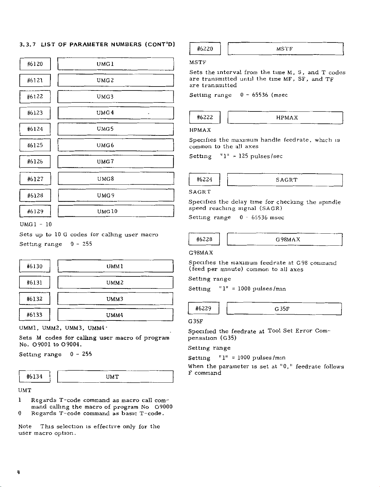
3.3.7
LIST
OF
PARAMETER
NUMBERS
(CONT'D)
#6220
MSTF
#6120
#6121
6122
#
#6123
#6124
#6125
#6126
#6127
#6128
#6129
UMG
Sets
Setting
#6130
#6131
#6132
#6133
UMMl,
Sets
No.
Setting
#6134
-
1
up
UMM2,
M
09001
10
to
range
codes
to
range
10
O9004.
codes
G
0
UMM3,
for
0
255
-
calling
255
-
UMG1
UMG2
UMG3
UMG4
UMG5
UMG6
UMG7
UMG8
UMG9
UMG10
for
UMM4
user
calling
UMMl
UMM2
UMM3
UMM4
•
UMT
user
macro
macro
of
program
MSTF
the
Sets
are
transmitted
transmitted
are
Setting
#6222
HPMAX
Specifies
common
Setting
#6224
SAGRT
Specifies
speed
Setting
#6228
G98MAX
Specifies
(feed
per
Setting
Setting
#6229
G35F
Specified
pensation
Setting
Setting
When
F
the
command
interval
range
the
to
the
"1"
the
reaching
range
the
minute)
range
"1"
the
(G35)
range
"1"
parameter
from
until
0-65536
maximum
all
axes
125
-
delay
signal
0
maximum
1000
=
feedrate
1000
=
the
the
handle
pulses/sec
time
(SAGR)
-
65536
feedrate
common
pulses/min
at
pulses
set
is
time
time
(msec
for
msec
to
G35F
Tool
/min
at
M,
MF,
HPMAX
feedrate,
SAGRT
checking
G98MAX
at
all
axes
Set
"0,"
S,
and
SF,
the
G98
Error
feedrate
T
and
TF
which
spindle
command
Com¬
follows
codes
is
UMT
1
0
Note
user
4
Regards
mand
Regards
This
macro
T-code
calling
T-code
selection
option.
the
command
macro
command
is
effective
of
as
macro
program
basic
as
only
call
No
T-code.
for
the
com¬
0
9000
Page 67

#6230
NEGNR
When
pensation
movement
arc
This
value,
arc
affect
Setting
Setting
The
corner
AX
AY
Standard
#6231
ROVFO
Specifies
Override.
Setting
Setting
circular
a
the
range
range
outside
follows
parameter
if
workpiece
Least
arc
NEGNR
S
NEGNR
i
the
"1"
this
0
input
setting
setting
AX
FO
125
=
is
path
a
corner
describing
arc
surface
-
65536
increment
=
*z
speed
pulses/sec
NEGNR
drawn
approaching
used
is
movement
is
ignored
5>
ROVFO
Rapid
for
Tool
in
very
a
to
set
considered
is
machining
when
Traverse
small
the
Radius
180°,
circular
critical
Com¬
the
to
Setting
Setting
Switch
Position
10
11
12
13
14
15
16
17
18
19
20
21
22
23
24
25
26
27
28
29
30
31
0
1
2
3
4
5
6
7
8
9
range
"1"
"1"
Feedrate
Override
%
10
20
30
40
50
60
70
80
90
100
110
120
130
140
150
160
170
180
190
200
0
0
0
0
0
0
0
0
0
0
0
0
5
mm/min
-
0
05
=
m/min
Parameter
Number
0
#6233
#6234
#6235
#6236
#6237
#6238
#6239
#6240
#6241
#6242
#6243
#6244
#6245
#6246
#6247
#6248
#6249
#6250
#6251
#6252
#6253
#6254
#6255
#6256
#6257
#6258
#6259
#6260
#6261
#6262
#6263
#6264
(metric
(inch
Setting
10
12
15
20
25
30
40
50
60
80
100
120
150
200
250
300
400
500
600
800
1000
1200
1500
2000
2500
3000
1
0
2
4
6
8
output)
output)
Continuous
Manual
mm
/min
10
12
15
20
25
30
40
50
60
80
100
120
150
200
250
300
400
500
600
800
1000
1200
1500
2000
2500
3000
Feedrate
0
1
2
4
6
8
#6232
G31F
Specifies
Setting
Setting:
This
setting
(SKPFED)
#6233
5
#6264
-JOG
JOGO
Specify
the
on
range:
the
]og
the
"1"
is
1.
=
31
feedrates
feedrate
feedrate
"1"
1
mm/min
=
effective
1000
=
for
select
m
the
pulses
when
JOGO
JOG31
i
the
switch
G31F
function
skip
/mm
parameter
5
respective
(G31)
#6019D4
positions
#6266
#6267
#6268
#6269
MACGR1-MACGR4
spindle
Sets
4
and
Setting
the
When
governed.
orderly.
speed
range
setting
MACGR1
MACGR2
MACGR
3
MACGR4
2,
gear
is
1,
not
for
0,
limit
(rpm)
the
speed
upper
-
0
6000
is
at
3,
65
Page 68

3.3.7
#6270
GRSREV
Sets
the
when
Setting
Setting
#6271
LIST
gear
value
range
speed
shift
OF
PARAMETER
command
input
Gear
Spindle
2047
x
Gear
Spindle
32512
x
-
0
NUMBERS
GRSREV
is
spindle
12-bit
spindle
Analog
GR1REV
to
given
max
=
output
max
=
output
(GRS)
shift
motor
(Command
---
shift
motor
(Command
---
6000
spindle
motor
10
motor
10
output
speed
V)
speed
V)
(CONT'D)
motor
speed
speed
Specify
spectively
an
by
Setting
MOTOR
SPINDLE
COMMAND
SPEED
10V
vi4T[
the
input
range
for
(CR1REV)
-
(MACCR
-
minimum
gears
signal
L
2
#6
-#6266
#
62
(MiCCR
of
3
(rpm)
2]
and
-
2}
the
-
-
4
t
#
(CR
#
(MACCR
-#6278
(M1CCR3)
spindle,
each
6273
3REV)
6268
speed
1,
2,
-
6000
0
[
71
1)
76
1)
(CR
-
(MACCR
#6272
2REV)
#6267
-#6277
(M1CCR
-
3)
re¬
selected
L
#62
(CR4REV)
#6269
(MACCR
-#6279
(MICCRO
(rpm)
74
4)
#6272
#6273
#6274
GR1REV-GR4REV
the
for
signal
the
range
the
operation
range
maximum
gears
spindle
Specify
tively,
an
input
when
ble
Setting
#6275
GSCREV:
Specifies
a
spindle
Setting
#6276
speed
0
1,
Set
0
-
-
speed
2,
3
the
command
6000
motor
(GSC)
6000
(rpm)
GR2REV
GR3REV
GR4REV
of
the
and4each
spindle
voltage
(rpm)
GSCREV
speed
input
is
MICGR1
spindle,
selected
speed
is
in
effect
entered
respec¬
applica¬
10
V.
when
by
#6280
#6281
RPDX,
Specify
axis,
Setting
Setting1
RPDZ
the
rapid
respectively
range.
"1"
#6286
#6287
ACCX1,ACCZ1
the
and
time
Z-axis,
"1"
.
constant
Set
X-
Setting
#6304
traverse
0-3200
125
=
respectively
125/8
=
pulses/sec
Linear
for
xlO3
pulses
RPDX
RPDZ
rate
ACCX1
ACCZ1
XREFP
for
X-
and
Accel/Decel
/sec2
Z-
for
66
#6277
#6278
#6279
MICGR2
MICGR3
MICGR4
#6305
XREFP,
Sets
Return,
Setting
Setting
ZREFP
traverse
the
respectively,
range
"1"
=
1
0
pulse
distance
on
65535
-
for
the
ZREFP
Reference
X-
and
Point
Z-axes.
Page 69

#6310
XREFV1
#6328
XPERST
#6311
XREFVl,
Specify
Return,
Setting
Setting:
#6316
#6317
XREFV2,
Specify
Return,
Setting
Setting:
ZREFVl
the
respectively,
range:
"1"
ZREFV2
the
approach
respectively,
range:
"1"
v
approach
0
125
—
0
125
=
DECELERATION
10
RAf
(
5
628a
/
—
r~wc
-
j
speed
on
200
-
pulses
speed
on
-
200
pulses/sec
TRAVERSE
628!)
8
WIDTH
j-1-
t
ZREFVl
1
the
X-
/sec
XREFV2
ZREFV
2
for
the
X-
POINT
RATE
APPROACH
(8
631
a
APPROACH
(8
TRAVERSE
(
8
—
-
Reference
for
and
2
Reference
and
SPEED
1)
8
631
SPEED
6316,
8
631
6304
8
SPEED
—
DECEL
Z-axes
Z-axes
I
2
7)
DISTANCE
6305)
SEQUENCE
LS
SIGN
Point
Point
#6329
XPERST,
Specify
screw
and
Setting
the
Error
Z-axes
range
#6334
#6335
XPEROR,
Specify
compensation,
Setting
range:
#6342
SIDREF
the
Sets
Setting
Setting
range
#6343
ZPERST:
number
Compensation,
ZPEROR:
reference
the
reference
"1"
=
of
-
0
255
respectively,
0-255
point
-
0
4095
1
pulse
the
point
(
for
=
ZPERST
start
point
respectively,
XPEROR
ZPEROR
for
Leadscrew
on
the
SIDREF
spindle
360/4096
SIDRV1
for
and
X-
indexing
deg)
Lead-
on
Error
X-
Z-axes.
Reference
#6010
#6322
#6323
XPERED,
Specify
Error
Z-a\es
Setting
—
point
(ZRNDRX
ZPERED:
the
Compnesation
number
range
Jiuuuufll
AREA
A
return
ZRNDRZ)
,
0
-
of
,
respectively,
255
!
C
direction
the
AREA
XPERED
ZPERED
end
point
B
ZERO
on
POINT
for
the
SIGN
Leadscrew
X-
and
SIDRV1
Sets
the
Setting
Setting
#6344
SIDCRP
the
Sets
Setting
Setting
#6345
SIDCRP:
the
Sets
Setting
Setting
spindle
range-
1
spindle
range
"1"
spindle
range
1=1
=0.31
=
speed
0
-
mV
indexing
-
0
31
0
indexing
-
0
pulse
for
32512
31512
mV
4095
(=
spindle
SIDCRP
creep
SIDCRP
creep
360/4096
indexing.
speed
start
deg)
I
position
67
Page 70

3.3.7
LIST
OF
PARAMETER
NUMBERS
(CONT'D)
#6624
XBPTS
i
#6346
SIDGEP
Sets
2
No
Setting
Setting
#6600
#6601
XSL1P
Specify
Stored
and
Z-axes
Setting
Setting*
#6606
the
start
,
spindle
range
1
ZSLlP
the
Stroke
range
"l11
position
1
pulse
=
plus
Limit
1
=
indexing
-
0
4095
direction
1,
0
-
99999999
pulse
command
(=
360/4096
boundary
respectively,
SIDGEP
XSL1P
ZSLlP
XSL1M
deg)
voltage
value
on
the
for
gain
X-,
#6625
XBPTS,
Specify
Z-axis,
on
touch
of
X-
#6630
#6631
XSETI
Specify
System
tively,
should
the
of
the
Setting
Setting
and
ZSETI.
on
be
first
coordinate
ZBPTS
absolute
the
respectively
switch
Z-axis.
value
the
Setting
range
the
in
set
reference
11
1"
=
X-,
coordinate
where
during
for
at
the
and
inches
point
system
-99999999
0
0001
tool
Automatic
of
time
Z-axes
for
and
to
-
in
ZBPTS
value
reference
error
XSETI
ZSETI
Coordinate
inch
A
the
distance
the
be
established
99999999
of
tool
compensation
input,
desired
reference
X-
and
turns
respec¬
value
between
point
#6607
XSL1M,
Specify
Stored
Z-axes
Setting
Setting:
#6612
#6613
XZP2L,
Specify
second
Z-axes
Setting
Setting.
ZSL1M
the
Stroke
range
"1"
'
ZZP2L
the
reference
range
"1"
minus
Limit
0
=1
distance
-99999999
1
=
direction
1,
-
99999999
pulse
between
point,
pulse
ZSL1M
boundary
respectively,
XZP2L
ZZP2L
the
respectively,
99999999
-
first
on
value
the
and
on
the
X-
the
for
,
X-,
#6636
#6637
XSETM,
Specify
System
spectively,
value
tance
should
between
reference
established
Setting
Setting
#6642
#6643
XPEINT,
Specify
Error
Compensation,
Z-axes
Setting
Setting-
ZSETM.
the
Setting
on
point
range
"1"
ZPEINT
the
compensation
range
"I"
value
be
=
=
at
the
the
0
1
for
Automatic
the
time
X-,
and
set
in
millimeters
first
of
the
coordinate
-99999999
mm
001
respectively,
-99999999
pulse
XSETM
ZSETM
of
Z-axes
reference
-
99999999
XPEINT
ZPEINT
inverval
-
99999999
Coordinate
metric
for
point
system
input,
A
the
in
Leadscrew
on
desired
and
the
dis¬
to
X-
re¬
the
be
and
68
Page 71

#8000
s
#8255
PEMNO-PEMN
Specify
Error
the
Compensation
255
respective
values
PEMNO
s
PEMN255
of
Leadscrcw
Setting
range
0
0
"1"
Setting
Output
=
Incremental/absolute
for
6323,
#6023Dy
compensation
6328,
parameter
Axis
#6322,
-
115
-
±128
designation
(PERIAB)
is
and
(Incremental
(Absolute
increment
specified
6329
designation)
designation)
is
selected
by
parameters
by
function
This
screw
pensation
after
compensation
tween
error
completion
the
specified
Compensation
of
No
Compensation
Compensation
Data
Compensation
correction
setting
Minimum
Compensation
automatically
on
data
data
reference
points
axes
base
interval
system
value
compensation
One-time-compensation
(Compensation
Notes
1
Regardless
the
difference
values
multiplication)
—127
pulses
of
correction
on
taken
are
REFERENCE
POINT
set
as
2.
3
sation
sation
Maximum
is
is
No.
arbitrary
points
r
+
\
0
1
0
o
-
10
I
Til
|«oc«(eooi|Bixe)aoo3iBoo<
«
o+i
o
o+io
|l
II
v!i,4!/j!AIBgW!?3ffWWaBinng
F5I
APPENDIX
compensate
each
axis
according
set
by
parameter
of
reference
are
point
X,
points
point
made
on
on
Z
axes
256
Reference
6000
point
each
Pulses
Absolute/incremental
(Set
by
[PERIAB])
unit
multiplication
factor.
value
multiplication)
of
absolute
between
should
value
Compensation
this
value.
far
as
within
COMPENSATION
6000
A
)+
+
o
I
1
I
II
laooslaocstaogrlsooBiacogJ
in
points
256
]+
o+io-
III
II
the
PULSES
i
/incremental
neighboring
(15
be
below.
and
case
on
total
LEADSCREW
MEASURED
+2+2-
,
Vl
STORED
for
to
the
is
and
effective
return
distances
the
and
axis
Max.
point
or
more
Parameter
)
1
pulse
increment)
put
#6023D7
(least
3X
15
pulses
setting,
compen¬
x
pulses
of
absolute
compen¬
multiplication
each
axis
compensation
INTERVAL
MM)
(=
6
ERROR
AXIS
X
ABSOLUTE
AMOUNT
SET
INCREMENTAL
AMOUNT
SET
COMPENSATION
PARAMETERS
LEADSCREW
lead-
com¬
The
be¬
out¬
max.
max.
setting
can
be
ERROR
Compensation
interval
Absolute
mental
switchable
Compensation
reference
Compensation
max
Compensation
min
Compensation
value
point
Compensation
multiplication
factor
X
AXIS
COMPENSATION
Table
Axis
X
Z
/incre¬
settig
X
no
Z
point
point
X
Z
X
z
NUMBER
««>*«!
632
2
606
8
6642
X
Z
X
Z
_
I
(
I
6000
each
on
COMPENSATION
_
BASE
r
I
ffiim
-
*
(
f
am
]
*
*
MSnSi
1*60230,1
3
1
Parameter
1
#6642
(XPEINT)
#6643
(ZPEINT)
#6023D7
(PERIAB)
#6334
(XPEROR)
#6335
(ZPEROR)
#5322
(XPERED)
15323
(
ZPERED
15328
(XPERST)
#5329
(ZPERST)
#8000
#6068
(XPERML)
#5559
(ZPERML)
-
,
J
‘
|
o
99
I!£2DN
V
)
-
#8255
7
/
'
—
I
0
1
F
unctions
6000
OR
MORE
1
'Tn
"
11
Value
eter
pensation
each
8000
written
0-±7
tal
0-±
lute
"1"
0
"1"
PARAMETER
COMPENSATION
AMOUNT
EACH
0"
1"
to
9
8000
8001
f
8002
*
9
8003
8004
*
8005
*
8006
*
8007
*
8008
*
S
8009
80
0
»
8098
8099
*
*6100
setting)
pulse
=
Incremen¬
=
tal
setting
Absolute
=
setting
of
param¬
#
of
point
will
(Incremen¬
(Abso¬
127
setting)
pulse
=1
3
IX
=
ON
POINT
-1
+
+
10
com¬
on
minus
be
OF
0
0
0
1
0
0
o
I
0
C/3CU
2ÿ
M
3
i
x
2
O
CO
z
o
cu
o
o
£
w
o
3
69
Page 72

£
YASKA
Better
A
If/;
TOKYO
Phone
YASKAWA
Chicago
305
Phone
Los
1481
Phone
YASKAWA
Monschauerstrasse
Phone
YASKAWA
OFFICE
(03)
91
284
ELECTRIC
(
Office
(312)
Myford
1
(714)
(02
Drive
564
Office
731
ELECTRIC
11
>501
Northbrook
Road
Era
Angeles
\
Tomorrow
Ohtemachi
Telex
1 1
AMERICA,
YASNAC
Telex
0770
Tustm
Telex
6841
EUROPE
4000
1
127
Telex
ior
Bldg
222
INC
America)
Illinois
(230)
Caliiorma
(230)
GmbH
Dusseldorl
(41
)
Industry
through
Electric
ChiyodakuTokyo
YASKWA
2273
SUBSIDIARY
USA
60062
YSKW
270197
USA
92680
YASKAWAUS
678396
SUBSIDIARY
Germany
West
1
I
YASD
8S88673
Automation
Mfg.
100
(03)
Fax
J
YSNC
Fax
D
Japan
284
NBRK
TSTN
(02
Co.,
9034
Fax
1)
507737
1
Fax
Ltd.
(312)
(714)
564
730
3276
8294
Printed
in
Japan
March
1983
83-3
0.6TA
 Loading...