

Page 1
Machine Controller MP2000 Series
262IF-01
FL-net Communication Module
USER'S MANUAL
Model: JAPMC-CM2303-E
262IF-01
RUN
TX
-
TEST
ONOFF
FL-net
LINK
100M
ERR
LNK
RX
FL-net Overview
Overview of 262IF-01 Module
Mounting and Starting the Module
FL-net Transmission Definition
Details of FL-net
Message Send and Receive Functions
Troubleshooting
Appendices
1
2
3
4
5
6
7
App
MANUAL NO. SIEP C880700 36B
Page 2

Copyright © 2008 YASKAWA ELECTRIC CORPORATION
All rights reserved. No part of this publication may be reproduced, stored in a retrieval system, or
transmitted, in any form, or by any means, mechanical, electronic, photocopying, recording, or otherwise, without the prior written permission of Yaskawa. No patent liability is assumed with respect to
the use of the information contained herein. Moreover, because Yaskawa is constantly striving to
improve its high-quality products, the information contained in this manual is subject to change without
notice. Every precaution has been taken in the preparation of this manual. Nevertheless, Yaskawa
assumes no responsibility for errors or omissions. Neither is any liability assumed for damages resulting from the use of the information contained in this publication.
Page 3

Purpose
Chapter
Selecting
Models and
Peripheral
Devices
Studying
Specifications
and Ratings
Designing
the
System
Panel
Installation
and Wiring
Tria l
Operation
Maintenance
and
Inspection
Chapter 1 FL-net Overview 9 − 9 −− −
Chapter 2 Overview of 262IF-01
Module
9 9 999 9
Chapter 3 Mounting and Starting
the Module
− 9 999 9
Chapter 4 FL-net Transmission
Definition
− 99− 99
Chapter 5 Details of FL-net 9 − 999 9
Chapter 6 Message Send and
Receive Functions
−−9 − 9 −
Chapter 7 Troubleshooting − 9 999 9
This symbol is used to indicate important information that should be memorized or minor precautions,
such as precautions that will result in alarms if not heeded.
S-ON
= /S-ON
P-CON
= /P-CON
Using this Manual
Read this manual thoroughly before using 262IF-01. This manual describes MP2000 Series Machine Controller FL-net
Communication Module 262IF-01. Keep this manual in a safe place for future reference.
Basic Terms
Unless otherwise specified, the following definitions are used:
• MP2000 Series Machine Controller:
• PLC: Programmable Logic Controller
• MPE720:
MP2100M, MP2200, MP2300, MP2310, MP2300S, and MP2500MD
Machine Controllers
The Programming Device Software or a personal computer running the Programming Device Software
Manual Configuration
This manual consists of the chapters listed in the following table. Read the chapters of this manual as required by the
purpose.
Graphic Symbols Used in this Manual
The graphic symbols used in this manual indicate the following type of information.
Indication of Reverse Signals
In this manual, the names of reverse signals (ones that are valid when low) are written with a forward slash (/) before
the signal name, as shown in the following example:
<Notation Examples>
iii
Page 4

R
Related Manuals
The following table lists the manuals relating to the MP2000 Series Machine Controller 262IF-01 Module. Refer to
these manuals as required.
Manual Name Manual Number Contents
Machine Controller MP2100/MP2100M
User's Manual
Design and Maintenance
Machine Controller MP2200
User's Manual
Machine Controller MP2300
Basic Module User's Manual
Machine Controller MP2310
Basic Module User’s Manual
Machine Controller MP2300S
Basic Module User’s Manual
Machine Controller MP2500/MP2500M/
MP2500D/MP2500MD User's Manual
Machine Controller MP2000 Series
Motion Module Built-in SVB/SVB-01
User's Manual
Machine Controller MP2000 Series
Communication Module User’s Manual
Machine Controller MP900/MP2000 Series
User's Manual: Ladder Programming
Machine Controller MP2000 Series User's
Manual: Motion Programming
Machine Controller MP2000 Series
MPE720 Programming Device Version 6
User's Manual
Machine Controller MP900/MP2000 Series
MPE720 Software for Programming Device
User's Manual
Machine Controller MP900/MP2000 Series
New Ladder Editor Programming Manual
Machine Controller MP900/MP2000 Series
New Ladder Editor User's Manual
Machine Controller MP920
User's Manual
Communication Modules
SIEPC88070001
SIEPC88070014
SIEPC88070003
SIEPC88073201
SIEPC88073200
SIEPC88075200
SIEPC88070033
SIEPC88070004
SIE-C887-1.2
SIEPC88070038
SIEPC88070030
SIEPC88070005
SIE-C887-13.1
SIE-C887-13.2
SIE-C887-2.6
Describes how to use the MP2100 and MP2100M
Machine Controllers.
Describes how to use the MP2200 Machine Controller and the modules that can be connected.
Describes how to use the MP2300 Basic Module
and the modules that can be connected.
Describes how to use the MP2310 Basic Module
and the modules that can be connected.
Describes how to use the MP2300S Basic Module
and the modules that can be connected.
Describes how to use the MP2500, MP2500M,
MP2500D, and MP2500MD Machine Controllers.
Provides a detailed description on the MP2000
Series Machine Controller built-in SVB Module
and slot-mounting optional SVB-01 Module.
Provides the information on the Communication
Module that can be connected to MP2000 Series
Machine Controller and the communication methods.
Describes the instructions used in MP900/MP2000
ladder programming.
Describes the instructions used in MP2000 motion
programming.
Describes how to install and operate the programming tool MPE720 version 6 for MP2000 Series
Machine Controllers.
Describes how to install and operate the MP900/
MP2000 Series programming system (MPE720).
Describes the programming instructions of the New
Ladder Editor, which assists MP900/MP2000
Series design and maintenance.
Describes the operating methods of the New Ladder
Editor, which assists MP900/MP2000 Series design
and maintenance.
Describes the functions, specifications, and application methods of the MP920 Communication Modules (217IF, 215IF, and 218IF).
Copyrights
DeviceNet is a registered trademark of the ODVA (Open DeviceNet Venders Association).
Ethernet is a registered trademark of the Xerox Corporation.
PROFIBUS is a trademark of the PROFIBUS User Organization.
MPLINK is a trademark of the Yaskawa Electric Corporation.
MECHATROLINK is a trademark of the MECHATROLINK Members Association.
Other product names and company names are the trademarks or registered trademarks of the respective company.
“TM” and the mark do not appear with product or company names in this manual.
iv
Page 5

WARNING
CAUTION
CAUTION
PROHIBITED
●
WARNING
Safety Information
The following conventions are used to indicate precautions in this manual. Information marked as shown below is
important for the safety of the user. Always read this information and heed the precautions that are provided. The conventions are as follows:
Indicates precautions that, if not heeded, could possibly result in loss of life or serious injury.
Indicates precautions that, if not heeded, could result in relatively serious or minor injury,
or property damage.
If not heeded, even precautions classified under can lead to serious results
depending on circumstances.
Indicates prohibited actions. Specific prohibitions are indicated inside .
For example, indicates no fire or open flame.
MANDATORY
Indicates mandatory actions. Specific actions are indicated inside .
For example, indicates that grounding is required.
Safety Precautions
The following precautions are for checking products on delivery, storage, transportation, installation, wiring, operation,
application, inspection, and disposal. These precautions are important and must be observed.
General Precautions
Before starting operation while connected to the machine, ensure that an emergency stop procedure has
been provided and is working correctly.
There is a risk of injury.
Do not touch anything inside the product.
There is a risk of electrical shock.
Always keep the front cover attached when power is being supplied.
There is a risk of electrical shock.
Observe all procedures and precautions given in this manual for trial operation.
Operating mistakes while the Servomotor and machine are connected can cause damage to the machine or
even accidents resulting in injury or death.
Do not remove the front cover, cables, connector, or options while power is being supplied.
There is a risk of electrical shock.
Do not damage, pull on, apply excessive force to, place heavy objects on, or pinch cables.
There is a risk of electrical shock, operational failure of the product, or burning.
Do not attempt to modify the product in any way.
There is a risk of injury or device damage.
Do not approach the machine when there is a momentary interruption to the power supply. When power is
restored, the MP2000 Series Machine Controller or machine connected to it may start operation suddenly.
Provide suitable safety measures to protect people when operation restarts.
There is a risk of injury.
Do not allow installation, disassembly, or repairs to be performed by anyone other than specified person-
nel.
There is a risk of electrical shock or injury.
v
Page 6

CAUTION
CAUTION
Storage and Transportation
Do not store or install the product in locations subject to the following. There is a risk of fire, electric shock,
and machine product damage.
Direct sunlight
Ambient temperatures exceeding the storage or operating conditions
Ambient humidity exceeding the storage or operating conditions
Extreme changes in temperature that would result in condensation
Corrosive or flammable gas
Excessive dust, dirt, salt, or metallic powder
Water, oil, or chemicals
Vibration or shock
Do not overload the product during transportation.
There is a risk of injury or an accident.
Never subject the product to an atmosphere containing halogen (fluorine, chlorine, bromine, or iodine) dur-
ing transportation or installation.
There is a risk of device damage or an accident.
If disinfectants or insecticides must be used to treat packing materials such as wooden frames, pallets, or
plywood, the packing materials must be treated before the product is packaged, and methods other than
fumigation must be used.
Example: Heat treatment, where materials are kiln-dried to a core temperature of 56
minutes or more.
If the electronic products, which include stand-alone products and products installed in machines, are packed
with fumigated wooden materials, the electrical components may be greatly damaged by the gases or fumes
resulting from the fumigation process. In particular, disinfectants containing halogen, which includes chlorine, fluorine, bromine, or iodine can contribute to the erosion of the capacitors.
°C for 30
Installation
Never use the product in locations subject to water, corrosive atmospheres, or flammable gas, or near
burnable objects.
There is a risk of electrical shock or fire.
Do not step on the product or place heavy objects on the product.
There is a risk of injury.
Do not block the air exhaust port on the product. Do not allow foreign objects to enter the product.
There is a risk of element deterioration inside, an accident, or fire.
Always mount the product in the specified orientation.
There is a risk of an accident.
Do not subject the product to strong shock.
There is a risk of an accident.
vi
Page 7
CAUTION
CAUTION
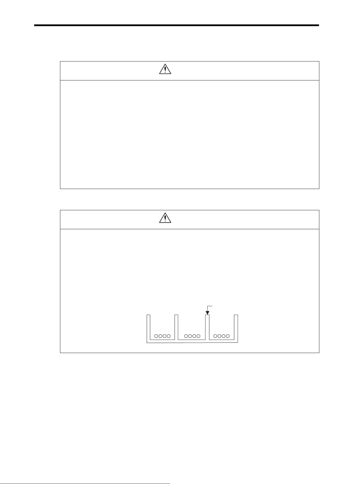
Steel separator
Example of Separated External Cables
Power circuit
cables
General
control circuit
cables
Digital I/O
signal cables
Wiring
Check the wiring to be sure it has been performed correctly.
There is a risk of motor run-away, injury, or an accident.
Always use a power supply of the specified voltage.
There is a risk of burning.
In places with poor power supply conditions, take all steps necessary to ensure that the input power is sup-
plied within the specified voltage range.
There is a risk of device damage.
Install breakers and other safety measures to provide protection against shorts in external wiring.
There is a risk of fire.
Provide sufficient shielding when using the product in the locations subject to the following.
There is a risk of device damage.
Noise, such as from static electricity
Strong electromagnetic or magnetic fields
Radiation
Near power lines
Selecting, Separating, and Laying External Cables
Consider the following items when selecting the I/O signal lines (external cables) to connect the product to
external devices.
Mechanical strength
Noise interference
Wiring distance
Signal voltage, etc.
Separate the I/O signal lines from the power lines both inside and outside the control box to reduce the
influence of noise from the power lines.
If the I/O signal lines and power lines are not separated properly, malfunctioning may result.
vii
Page 8
CAUTION
CAUTION
Maintenance and Inspection Precautions
Do not attempt to disassemble the product.
There is a risk of electrical shock or injury.
Do not change wiring while power is being supplied.
There is a risk of electrical shock or injury.
Disposal Precautions
Dispose of the product as general industrial waste.
General Precautions
Observe the following general precautions
to ensure safe application.
The products shown in illustrations in this manual are sometimes shown without covers or protective
guards. Always replace the cover or protective guard as specified first, and then operate the products in
accordance with the manual.
The drawings presented in this manual are typical examples and may not match the product you received.
If the manual must be ordered due to loss or damage, inform your nearest Yaskawa representative or one
of the offices listed on the back of this manual.
viii
Page 9

Warranty
( 1 ) Details of Warranty
Warranty Period
The warranty period for a product that was purchased (hereinafter called “delivered product”) is one year from the time
of delivery to the location specified by the customer or 18 months from the time of shipment from the Yaskawa factory,
whichever is sooner.
Warranty Scope
Yaskawa shall replace or repair a defective product free of charge if a defect attributable to Yaskawa occurs during the
warranty period above. This warranty does not cover defects caused by the delivered product reaching the end of its
service life and replacement of parts that require replacement or that have a limited service life.
This warranty does not cover failures that result from any of the following causes.
1. Improper handling, abuse, or use in unsuitable conditions or in environments not described in product catalogs or
manuals, or in any separately agreed-upon specifications
2. Causes not attributable to the delivered product itself
3. Modifications or repairs not performed by Yaskawa
4. Abuse of the delivered product in a manner in which it was not originally intended
5. Causes that were not foreseeable with the scientific and technological understanding at the time of shipment from
Ya sk a wa
6. Events for which Yaskawa is not responsible, such as natural or human-made disasters
( 2 ) Limitations of Liability
1. Yaskawa shall in no event be responsible for any damage or loss of opportunity to the customer that arises due to
failure of the delivered product.
2. Yaskawa shall not be responsible for any programs (including parameter settings) or the results of program execution of the programs provided by the user or by a third party for use with programmable Yaskawa products.
3. The information described in product catalogs or manuals is provided for the purpose of the customer purchasing
the appropriate product for the intended application. The use thereof does not guarantee that there are no infringements of intellectual property rights or other proprietary rights of Yaskawa or third parties, nor does it construe a
license.
4. Yaskawa shall not be responsible for any damage arising from infringements of intellectual property rights or other
proprietary rights of third parties as a result of using the information described in catalogs or manuals.
ix
Page 10

( 3 ) Suitability for Use
1. It is the customer’s responsibility to confirm conformity with any standards, codes, or regulations that apply if the
Yaskawa product is used in combination with any other products.
2. The customer must confirm that the Yaskawa product is suitable for the systems, machines, and equipment used by
the customer.
3. Consult with Yaskawa to determine whether use in the following applications is acceptable. If use in the application
is acceptable, use the product with extra allowance in ratings and specifications, and provide safety measures to
minimize hazards in the event of failure.
• Outdoor use, use involving potential chemical contamination or electrical interference, or use in conditions or
environments not described in product catalogs or manuals
• Nuclear energy control systems, combustion systems, railroad systems, aviation systems, vehicle systems,
medical equipment, amusement machines, and installations subject to separate industry or government regulations
• Systems, machines, and equipment that may present a risk to life or property
• Systems that require a high degree of reliability, such as systems that supply gas, water, or electricity, or systems that operate continuously 24 hours a day
• Other systems that require a similar high degree of safety
4. Never use the product for an application involving serious risk to life or property without first ensuring that the system is designed to secure the required level of safety with risk warnings and redundancy, and that the Yaskawa
product is properly rated and installed.
5. The circuit examples and other application examples described in product catalogs and manuals are for reference.
Check the functionality and safety of the actual devices and equipment to be used before using the product.
6. Read and understand all use prohibitions and precautions, and operate the Yaskawa product correctly to prevent
accidental harm to third parties.
( 4 ) Specifications Change
The names, specifications, appearance, and accessories of products in product catalogs and manuals may be changed at
any time based on improvements and other reasons. The next editions of the revised catalogs or manuals will be published with updated code numbers. Consult with your Yaskawa representative to confirm the actual specifications
before purchasing a product.
x
Page 11

Contents
Using this Manual - - - - - - - - - - - - - - - - - - - - - - - - - - - - - - - - - - - - - - - - - - - - - - - - - - - - - - - iii
Safety Information - - - - - - - - - - - - - - - - - - - - - - - - - - - - - - - - - - - - - - - - - - - - - - - - - - - - - - - v
Safety Precautions - - - - - - - - - - - - - - - - - - - - - - - - - - - - - - - - - - - - - - - - - - - - - - - - - - - - - - v
Warranty - - - - - - - - - - - - - - - - - - - - - - - - - - - - - - - - - - - - - - - - - - - - - - - - - - - - - - - - - - - - - ix
1 FL-net Overview - - - - - - - - - - - - - - - - - - - - - - - - - - - - - - - - - - - - - - - - - - - - 1-1
1.1 What is FL-net? - - - - - - - - - - - - - - - - - - - - - - - - - - - - - - - - - - - - - - - - - - - - - 1-2
1.2 FL-net Protocol- - - - - - - - - - - - - - - - - - - - - - - - - - - - - - - - - - - - - - - - - - - - - - 1-2
1.3 FL-net Features - - - - - - - - - - - - - - - - - - - - - - - - - - - - - - - - - - - - - - - - - - - - - 1-3
1.4 FAQ on FL-net - - - - - - - - - - - - - - - - - - - - - - - - - - - - - - - - - - - - - - - - - - - - - - 1-4
1.5 Basic FL-net Terminology - - - - - - - - - - - - - - - - - - - - - - - - - - - - - - - - - - - - - - 1-6
2 Overview of 262IF-01 Module - - - - - - - - - - - - - - - - - - - - - - - - - - - - - - - - - - - 2-1
2.1 Overview of 262IF-01 Module - - - - - - - - - - - - - - - - - - - - - - - - - - - - - - - - - - - 2-2
2.1.1 Module Specifications - - - - - - - - - - - - - - - - - - - - - - - - - - - - - - - - - - - - - - - - - - - - - - - - - - - 2-3
2.1.2 Appearance and Connectors - - - - - - - - - - - - - - - - - - - - - - - - - - - - - - - - - - - - - - - - - - - - - - 2-6
2.1.3 Status Indicators (LEDs)- - - - - - - - - - - - - - - - - - - - - - - - - - - - - - - - - - - - - - - - - - - - - - - - - - 2-6
2.1.4 Communication Status Indicators (LED) (Included with Ethernet Connector) - - - - - - - - - - - - - 2-6
2.1.5 Switch Settings - - - - - - - - - - - - - - - - - - - - - - - - - - - - - - - - - - - - - - - - - - - - - - - - - - - - - - - - 2-7
2.2 Connection Specifications - - - - - - - - - - - - - - - - - - - - - - - - - - - - - - - - - - - - - - 2-8
2.2.1 Connector Specifications - - - - - - - - - - - - - - - - - - - - - - - - - - - - - - - - - - - - - - - - - - - - - - - - - 2-8
2.2.2 Cable Specifications - - - - - - - - - - - - - - - - - - - - - - - - - - - - - - - - - - - - - - - - - - - - - - - - - - - - 2-8
2.3 System Configuration Example - - - - - - - - - - - - - - - - - - - - - - - - - - - - - - - - - - 2-9
2.3.1 Small-scale Configuration - - - - - - - - - - - - - - - - - - - - - - - - - - - - - - - - - - - - - - - - - - - - - - - - 2-9
2.3.2 Basic Configuration - - - - - - - - - - - - - - - - - - - - - - - - - - - - - - - - - - - - - - - - - - - - - - - - - - - - - 2-9
2.3.3 Locally Concentrated Device Configuration - - - - - - - - - - - - - - - - - - - - - - - - - - - - - - - - - - - 2-10
2.3.4 Long Distant, Locally Distributed Device Configuration - - - - - - - - - - - - - - - - - - - - - - - - - - - 2-11
3 Mounting and Starting the Module - - - - - - - - - - - - - - - - - - - - - - - - - - - - - - - - 3-1
3.1 Applicable Machine Controllers and Supported Versions - - - - - - - - - - - - - - - - 3-2
3.1.1 Applicable Machine Controllers- - - - - - - - - - - - - - - - - - - - - - - - - - - - - - - - - - - - - - - - - - - - - 3-2
3.1.2 Supported CPU and MPE720 Versions - - - - - - - - - - - - - - - - - - - - - - - - - - - - - - - - - - - - - - - 3-2
3.2 Mounting and Removing a Module on Machine Controller - - - - - - - - - - - - - - - 3-3
3.2.1 Mounting a 262IF-01 Module - - - - - - - - - - - - - - - - - - - - - - - - - - - - - - - - - - - - - - - - - - - - - - 3-3
3.2.2 Removing a 262IF-01 Module- - - - - - - - - - - - - - - - - - - - - - - - - - - - - - - - - - - - - - - - - - - - - - 3-6
3.3 Setting the Communication Manager - - - - - - - - - - - - - - - - - - - - - - - - - - - - - - 3-8
3.3.1 Opening the Communication Manager - - - - - - - - - - - - - - - - - - - - - - - - - - - - - - - - - - - - - - - 3-8
3.3.2 Setting the Communication Manager- - - - - - - - - - - - - - - - - - - - - - - - - - - - - - - - - - - - - - - - - 3-9
3.4 Self-configuration - - - - - - - - - - - - - - - - - - - - - - - - - - - - - - - - - - - - - - - - - - - - 3-19
3.4.1 Executing Self-configuration - - - - - - - - - - - - - - - - - - - - - - - - - - - - - - - - - - - - - - - - - - - - - - 3-19
3.5 Starting the MPE720 and Setting Communication or Network Parameters - - - - 3-20
3.5.1 Starting MPE720 Ver. 6 and Setting Communication- - - - - - - - - - - - - - - - - - - - - - - - - - - - - 3-20
3.5.2 Starting MPE720 Ver. 5. and Setting the Network - - - - - - - - - - - - - - - - - - - - - - - - - - - 3-21
xi
Page 12

4 FL-net Transmission Definition - - - - - - - - - - - - - - - - - - - - - - - - - - - - - - - - - - 4-1
4.1 Displaying the FL-net Transmission Configuration Window- - - - - - - - - - - - - - - - 4-2
4.1.1 Displaying the Module Configuration Window - - - - - - - - - - - - - - - - - - - - - - - - - - - - - - - - - - 4-2
4.1.2 Displaying the FL-net Transmission Configuration Window
from the Module Configuration Window - - - - - - - - - - - - - - - - - - - - - - - - - - - - - - - - - - - - - - 4-3
4.2 FL-net Transmission Definition- - - - - - - - - - - - - - - - - - - - - - - - - - - - - - - - - - - - 4-4
4.2.1 Transmission Parameters Tab Page - - - - - - - - - - - - - - - - - - - - - - - - - - - - - - - - - - - - - - - - - 4-4
4.2.2 Link Assignment Tab Page - - - - - - - - - - - - - - - - - - - - - - - - - - - - - - - - - - - - - - - - - - - - - - - 4-6
4.2.3 Link Status Tab Page - - - - - - - - - - - - - - - - - - - - - - - - - - - - - - - - - - - - - - - - - - - - - - - - - - - 4-9
4.2.4 Status Detail Window - - - - - - - - - - - - - - - - - - - - - - - - - - - - - - - - - - - - - - - - - - - - - - - - - - 4-10
4.2.5 Status Tab Page - - - - - - - - - - - - - - - - - - - - - - - - - - - - - - - - - - - - - - - - - - - - - - - - - - - - - - 4-12
4.2.6 Network Configuration Window - - - - - - - - - - - - - - - - - - - - - - - - - - - - - - - - - - - - - - - - - - - 4-13
4.2.7 Saving FL-net Transmission Definitions - - - - - - - - - - - - - - - - - - - - - - - - - - - - - - - - - - - - - 4-14
5 Details of FL-net - - - - - - - - - - - - - - - - - - - - - - - - - - - - - - - - - - - - - - - - - - - - 5-1
5.1 Ethernet Segment Configuration Example - - - - - - - - - - - - - - - - - - - - - - - - - - - 5-2
5.1.1 10BASE5 System - - - - - - - - - - - - - - - - - - - - - - - - - - - - - - - - - - - - - - - - - - - - - - - - - - - - - - 5-2
5.1.2 10BASE-T System - - - - - - - - - - - - - - - - - - - - - - - - - - - - - - - - - - - - - - - - - - - - - - - - - - - - - 5-2
5.1.3 100BASE-TX system - - - - - - - - - - - - - - - - - - - - - - - - - - - - - - - - - - - - - - - - - - - - - - - - - - - 5-3
5.1.4 Ethernet IP Address - - - - - - - - - - - - - - - - - - - - - - - - - - - - - - - - - - - - - - - - - - - - - - - - - - - - 5-4
5.2 About FL-net - - - - - - - - - - - - - - - - - - - - - - - - - - - - - - - - - - - - - - - - - - - - - - - - 5-5
5.2.1 FL-net Overview - - - - - - - - - - - - - - - - - - - - - - - - - - - - - - - - - - - - - - - - - - - - - - - - - - - - - - - 5-5
5.3 FL-net Data Communication - - - - - - - - - - - - - - - - - - - - - - - - - - - - - - - - - - - - - 5-9
5.3.1 Cyclic Transmission - - - - - - - - - - - - - - - - - - - - - - - - - - - - - - - - - - - - - - - - - - - - - - - - - - - - 5-9
5.3.2 Message Transmission - - - - - - - - - - - - - - - - - - - - - - - - - - - - - - - - - - - - - - - - - - - - - - - - - 5-12
5.3.3 Details of Supported Messages - - - - - - - - - - - - - - - - - - - - - - - - - - - - - - - - - - - - - - - - - - - 5-14
6 Message Send and Receive Functions - - - - - - - - - - - - - - - - - - - - - - - - - - - - 6-1
6.1 Message Send Function - - - - - - - - - - - - - - - - - - - - - - - - - - - - - - - - - - - - - - - - 6-2
6.1.1 Outline Specifications - - - - - - - - - - - - - - - - - - - - - - - - - - - - - - - - - - - - - - - - - - - - - - - - - - - 6-2
6.1.2 MSG-SND Function Setting Example - - - - - - - - - - - - - - - - - - - - - - - - - - - - - - - - - - - - - - - - 6-3
6.1.3 Inputs and Outputs for the Message Send Function - - - - - - - - - - - - - - - - - - - - - - - - - - - - - - 6-3
6.1.4 Parameter List for MSG-SND Function - - - - - - - - - - - - - - - - - - - - - - - - - - - - - - - - - - - - - - - 6-9
6.1.5 Parameter Details for MSG-SND Function - - - - - - - - - - - - - - - - - - - - - - - - - - - - - - - - - - - 6-10
6.1.6 Specifying an FL-net Virtual Address Space Using the MSG-SND Function - - - - - - - - - - - - 6-15
6.1.7 Relationship among the Data Address, Data Size, and Offset
in the MSG-SND Function - - - - - - - - - - - - - - - - - - - - - - - - - - - - - - - - - - - - - - - - - - - - - - - 6-16
6.2 Message Receive Function - - - - - - - - - - - - - - - - - - - - - - - - - - - - - - - - - - - - - 6-17
6.2.1 Basic Specifications - - - - - - - - - - - - - - - - - - - - - - - - - - - - - - - - - - - - - - - - - - - - - - - - - - - 6-17
6.2.2 MSG-RCV Function Setting Example - - - - - - - - - - - - - - - - - - - - - - - - - - - - - - - - - - - - - - - 6-18
6.2.3 Inputs and Outputs for the Message Receive Function - - - - - - - - - - - - - - - - - - - - - - - - - - - 6-18
6.2.4 Parameter List for MSG-RCV Function - - - - - - - - - - - - - - - - - - - - - - - - - - - - - - - - - - - - - - 6-23
6.2.5 Parameter Details for MSG-RCV Function - - - - - - - - - - - - - - - - - - - - - - - - - - - - - - - - - - - 6-24
6.2.6 Relationship among the Data Address, Data Size, and Offset in the MSG-RCV Function - - 6-28
xii
6.3 Combination of FL-net Messages and Message Functions - - - - - - - - - - - - - - - 6-29
6.4 Displaying a Register List and Notes at Register Input - - - - - - - - - - - - - - - - - - 6-30
6.4.1 Displaying a Register List - - - - - - - - - - - - - - - - - - - - - - - - - - - - - - - - - - - - - - - - - - - - - - - 6-30
6.4.2 Notes at Register Input - - - - - - - - - - - - - - - - - - - - - - - - - - - - - - - - - - - - - - - - - - - - - - - - - 6-32
6.5 Programming Example - - - - - - - - - - - - - - - - - - - - - - - - - - - - - - - - - - - - - - - - 6-33
6.5.1 Word Block Data Read (Client) - - - - - - - - - - - - - - - - - - - - - - - - - - - - - - - - - - - - - - - - - - - 6-33
6.5.2 Word Block Data Write (Client)- - - - - - - - - - - - - - - - - - - - - - - - - - - - - - - - - - - - - - - - - - - - 6-36
Page 13

6.5.3 Word Block Data Read/Write (Server) - - - - - - - - - - - - - - - - - - - - - - - - - - - - - - - - - - - - - - - 6-39
6.5.4 Sending Request (Client)/Response (Server)
according to Non-procedure Protocol - - - - - - - - - - - - - - - - - - - - - - - - - - - - - - - - - - - - - - - 6-42
6.5.5 Sending Request/Receiving Response (Client)
according to Non-procedure Protocol - - - - - - - - - - - - - - - - - - - - - - - - - - - - - - - - - - - - - - - 6-45
6.5.6 Receiving Transparent Message Request (Server)- - - - - - - - - - - - - - - - - - - - - - - - - - - - - - 6-51
7 Troubleshooting- - - - - - - - - - - - - - - - - - - - - - - - - - - - - - - - - - - - - - - - - - - - - 7-1
7.1 Before Starting to Locate Faults - - - - - - - - - - - - - - - - - - - - - - - - - - - - - - - - - - 7-2
7.2 Common Network Problems and Countermeasures- - - - - - - - - - - - - - - - - - - - 7-3
7.2.1 When Communication Is not Possible or It Is Unstable - - - - - - - - - - - - - - - - - - - - - - - - - - - - 7-3
7.2.2 Confirming 262IF-01 Setting - - - - - - - - - - - - - - - - - - - - - - - - - - - - - - - - - - - - - - - - - - - - - - - 7-4
7.2.3 System I/O Error Status - - - - - - - - - - - - - - - - - - - - - - - - - - - - - - - - - - - - - - - - - - - - - - - - - - 7-5
7.2.4 Details on I/O Error Status - - - - - - - - - - - - - - - - - - - - - - - - - - - - - - - - - - - - - - - - - - - - - - - - 7-9
7.3 Notes on Regular Usage of FL-net - - - - - - - - - - - - - - - - - - - - - - - - - - - - - - - - 7-12
Appendices - - - - - - - - - - - - - - - - - - - - - - - - - - - - - - - - - - - - - - - - - - - - - - - - A-1
Appendix A Network System Definition - - - - - - - - - - - - - - - - - - - - - - - - - - - - - - - A-2
A.1 Communication Protocol Standard- - - - - - - - - - - - - - - - - - - - - - - - - - - - - - - - - - - - - - - - - - - - A-2
A.2 Hierarchical Structure of Communication Protocol- - - - - - - - - - - - - - - - - - - - - - - - - - - - - - - - - A-2
A.3 FL-net Physical Layer - - - - - - - - - - - - - - - - - - - - - - - - - - - - - - - - - - - - - - - - - - - - - - - - - - - - A-2
A.4 FL-net IP Address - - - - - - - - - - - - - - - - - - - - - - - - - - - - - - - - - - - - - - - - - - - - - - - - - - - - - - - A-3
A.5 FL-net Subnet Mask- - - - - - - - - - - - - - - - - - - - - - - - - - - - - - - - - - - - - - - - - - - - - - - - - - - - - - A-3
A.6 TCP/IP, UDP/IP Communication Protocol- - - - - - - - - - - - - - - - - - - - - - - - - - - - - - - - - - - - - - - A-4
A.7 FL-net Port Number - - - - - - - - - - - - - - - - - - - - - - - - - - - - - - - - - - - - - - - - - - - - - - - - - - - - - - A-4
A.8 FL-net Data Format - - - - - - - - - - - - - - - - - - - - - - - - - - - - - - - - - - - - - - - - - - - - - - - - - - - - - - A-5
Appendix B FL-net Network Management - - - - - - - - - - - - - - - - - - - - - - - - - - - - - A-7
B.1 FL-net Token Management - - - - - - - - - - - - - - - - - - - - - - - - - - - - - - - - - - - - - - - - - - - - - - - - - A-7
B.2 Joining/Leaving FL-net - - - - - - - - - - - - - - - - - - - - - - - - - - - - - - - - - - - - - - - - - - - - - - - - - - - - A-9
B.3 Node Status Management - - - - - - - - - - - - - - - - - - - - - - - - - - - - - - - - - - - - - - - - - - - - - - - - A-11
B.4 FL-net Local Node Management Table - - - - - - - - - - - - - - - - - - - - - - - - - - - - - - - - - - - - - - - A-11
B.5 FL-net Join Node Management Table - - - - - - - - - - - - - - - - - - - - - - - - - - - - - - - - - - - - - - - - A-12
B.6 FL-net Status Management- - - - - - - - - - - - - - - - - - - - - - - - - - - - - - - - - - - - - - - - - - - - - - - - A-13
B.7 FL-net Message Serial Number Management- - - - - - - - - - - - - - - - - - - - - - - - - - - - - - - - - - - A-13
Appendix C FL-net System Grounding - - - - - - - - - - - - - - - - - - - - - - - - - - - - - - - A-14
C.1 Overview - - - - - - - - - - - - - - - - - - - - - - - - - - - - - - - - - - - - - - - - - - - - - - - - - - - - - - - - - - - - A-14
C.2 Power Supply Wiring and Grounding - - - - - - - - - - - - - - - - - - - - - - - - - - - - - - - - - - - - - - - - - A-15
C.3 Network Equipment Connection in the FL-net System - - - - - - - - - - - - - - - - - - - - - - - - - - - - - A-16
C.4 Laying and Grounding a Wiring Duct and a Conduit - - - - - - - - - - - - - - - - - - - - - - - - - - - - - - A-17
C.5 FL-net Construction Work Check Sheet - - - - - - - - - - - - - - - - - - - - - - - - - - - - - - - - - - - - - - - A-18
Appendix D Supplement on FL-net Profile - - - - - - - - - - - - - - - - - - - - - - - - - - - - A-19
D.1 262IF-01 Profile- - - - - - - - - - - - - - - - - - - - - - - - - - - - - - - - - - - - - - - - - - - - - - - - - - - - - - - - A-19
D.2 ANS.1 Transfer Syntax Summary - - - - - - - - - - - - - - - - - - - - - - - - - - - - - - - - - - - - - - - - - - - A-20
Appendix E Differences from CP Series/262IF - - - - - - - - - - - - - - - - - - - - - - - - - A-23
INDEX - - - - - - - - - - - - - - - - - - - - - - - - - - - - - - - - - - - - - - - - - - - - - - - - - Index-1
Revision History
xiii
Page 14

1
FL-net Overview
1
FL-net Overview
This chapter gives an overview of FL-net.
For details on FL-net, refer to Chapter 5 Details of FL-net.
1.1 What is FL-net? - - - - - - - - - - - - - - - - - - - - - - - - - - - - - - - - - - - - - - - - - -1-2
1.2 FL-net Protocol - - - - - - - - - - - - - - - - - - - - - - - - - - - - - - - - - - - - - - - - - - -1-2
1.3 FL-net Features - - - - - - - - - - - - - - - - - - - - - - - - - - - - - - - - - - - - - - - - - -1-3
1.4 FAQ on FL-net - - - - - - - - - - - - - - - - - - - - - - - - - - - - - - - - - - - - - - - - - - -1-4
1.5 Basic FL-net Terminology - - - - - - - - - - - - - - - - - - - - - - - - - - - - - - - - - - -1-6
1-1
Page 15
1.1 What is FL-net?
MP2200
218IF-02 262IF-01
LIO-04SVB-01
CPU-02
LIO-04 LIO-04 LIO-01 LIO-01
MP2300
218IF-02 262IF-01
SVB-01
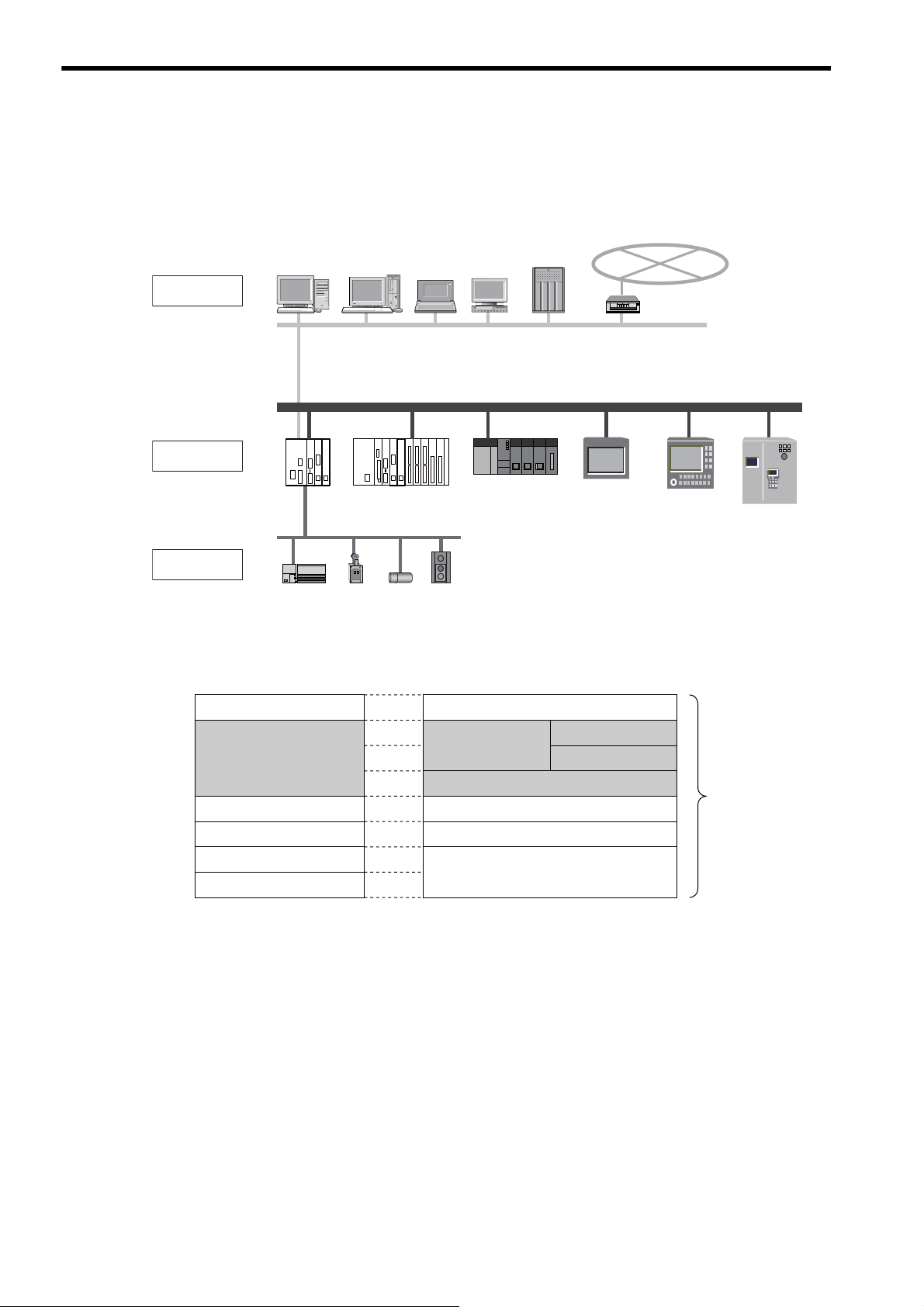
PC PC PC EWS
PLCPLCPLC
Server
WAN
Panel
controller
CNC RC
Sensor actuator
Computer
Controller
Equipment
Upper LAN Ethernet 䋨TCP/IP, UDP/IP䋩
FL-net (Ethernet-based control network)
Field network
1.1 What is FL-net?
As shown in Fig. 1.1, FL-net is a network capable of interconnecting various FA controllers such as the programmable
controllers (PLC) and computer numeric control equipment (CNC) from many manufacturers, and personal computers
for control and monitoring.
1.2 FL-net Protocol
The following shows a basic FL-net protocol structure.
The transport and network layers use UDP/IP, while the data link and physical layers use Ethernet.
Fig. 1.1 Example of FA Control Network Configuration
Application layer
FA link protocol layer
Transport layer
Network layer
Data link layer
Physical layer
Controller or interface
Service function
Cyclic transmission
Message transmission
Token function
UDP
IP
Ethernet
(Based on IEEE802.3)
Fig. 1.2 Basic FL-net Protocol Structure
FL-net
protocol
1-2
Page 16

1
FL-net Overview
1.3 FL-net Features
FL-net has the following features:
• Open control network
• Realization of multi-vendor environments
• FL-net is capable of interconnecting controllers such as the programmable controllers (PLC) and computer
numeric control equipment (CNC) from many manufacturers, and personal computers for control and monitoring.
In addition, FL-net has the following features.
Compliant with Worldwide Standards
Efficient communication based on standard UDP/IP is realized as well as de facto standard Ethernet for OA equipment
communication. Ethernet provides the following advantages.
– Low cost
Prevailing communication devices can be used, resulting in low cost.
– Availability of prevailing network devices
A wide variety of prevailing network devices such as transceivers, hubs, cables, and PC LAN cards for Ethernet
can be used.
1.3 FL-net Features
– Realization of high-speed communication
In the future, the baud rate can be increased to support 10 Mbps, 100 Mbps, and 1 Gbps.
– Communication via optical fiber cables
The prevailing Ethernet optical repeater allows optical fibers to be used in the corresponding section for communication over distances of 500 m or more, improves noise resistance, and prevents of surge currents caused by
lightning strikes in outside wiring.
Support of Necessary Communication Functions between FA Controllers
Because user requirements are fully examined as specifications, various features required for FA are supported.
– Large network
A maximum of 254 pieces of equipment (nodes) can be connected.
– Support of two types of communication functions according to purpose
The common memory function allows each node to share the same data through cyclic communication, and the
message communication function allows only necessary information to be transferred on demand.
– Large common memory
A large common memory (8 kbits + 8 kwords) is supported.
– Fast response
A fast response of 50 ms/32 nodes (2 kbits +2 kwords) can be realized.
– High reliability by masterless system
Because no master station is needed, each node can join or leave without affecting communications between
other nodes. Thus, each node can be turned ON or OFF and maintained independently.
1-3
Page 17

1.4 FAQ on FL-net
1.4 FAQ on FL-net
The following gives a list of frequently asked questions and answers.
Question Answer
1
What is Ethernet?
2
What is FL-net?
What is the difference between
3
FL-net and Ethernet?
How should we use the FN-net
4
unit?
What is a protocol?
5
What protocol is supported by
FL-net?
Does FL-net allow general PC
6
connections?
7
What is topology?
What types of network cables
are available? How long are
8
the cables and how many
nodes can be connected to
them?
When a system uses FL-net,
9
does it need a special Ethernet?
How should we make FL-net
10
connections?
Ethernet refers to a cable type specification, and is available with local area networks
(LAN). Ethernet enables data transfer between computers at a baud rate from 10 Mbps
to 100 Mbps.
Presently, the prevailing Ethernet cable for office automation is a 100-Mbp twisted pair
cable (UTP). Ethernet allows communication through the use of multi-vendor software
protocols.
FL-net refers to a network capable of interconnecting FA controllers such as programmable controllers (PLC) and computer numeric control (CNC) equipment so as to transfer control data at high speed between controllers.
Cables are identical to those employed for Ethernet.
Ethernet is used to connect controllers to the host computer or PC so that production
directions can be given or performance information can be obtained for informational or
control purposes. On the other hand, FL-net is used to connect controllers for highspeed control data transfer.
When one controller is used for both an FL-net to connect controllers and an Ethernet to
connect controllers to the host devices, care should be taken for correct cable connection.
The FL-net unit should be installed in FA controllers such as a programmable controller
(PLC) and computer numeric control (CNC) equipment so that data transfer can take
place cyclically between the controllers as long as link assignments for station numbers
(node numbers) and common memory (also called “link register”) are simply made in
the same manner as for regular PLC CPU link units. In this case, no special communication program is required for PLC, etc. In addition, when PLC memory contents or
communication parameters are read or written from PC, no special communication program is required for PLC, etc.
However, note that each controller should be provided with a communication program
when data transfer is attempted between controllers through message transmission.
Protocol refers to a set of rules required for communication.
FL-net employs an FL-net-dedicated FA link protocol that lies in the UDP/IP or upper
layers.
The FL-net units to be installed in FA controllers such as a programmable controller
(PLC) and computer numeric control (CNC) equipment are intelligent units with processors on their boards. Because PC Ethernet cards are non-intelligent cards called
“dumb cards,” it is generally recommended to use FL-net boards according to PC performance and usage.
A networking topology refers to a network wiring method. Though star (tree), bus, and
ring topologies are available as main topologies, they can be understood more easily
from a viewpoint of logical wiring rather than physical wiring.
A star topology is used for 10BASE-T/100BASE-TX in FL-net. On the other hand, a
bus topology is used for 10BASE5 in FL-net.
The following summarizes the standards, characteristics, and restrictions of the most
popular Ethernet cables.
•
10BASE-T/100BASE-TX: Twisted pair cable (UTP), maximum transmission dista
nce per segment: 100 m (500 m), maximum number of connectable nodes per seg-
ment: 254
• 10BASE5: Thick coaxial cable (yellow cable), maximum transmission distance per
segment: 500 m (2,500 m), maximum number of connectable nodes per segment: 100
(254)
• 10BASE-FL/100BASE-FX: Optical fiber cable, maximum transmission distance per
segment: 2,000 m, maximum number of connectable nodes per segment: 254
∗ Values in ( ) assume the use of repeaters.
No. To build an FL-net system, Ethernet is used (which is formally compliant with
IEEE802.3). Special specifications are not required.
Different types of Ethernet media can be interconnected with Ethernet cables through
repeaters, media conversion adaptors, etc. These products can be purchased from many
vendors.
1-4
Page 18

1
FL-net Overview
Question Answer
What cable should be used to
11
build an FL-net system?
How should we set FL-net IP
12
addresses?
How conformance and interconnectivity have been
13
assured among FL-net support
devices?
1.4 FAQ on FL-net
(cont’d)
Generally, cables should be used as follows.
• 10BASE5 (thick coaxial cable: yellow cable) is used for the backbone.
• 10BASE-T/100BASE-TX (twisted pair cable: UTP category 5) is used for cabling in
control panels and offices.
• 10BASE-FL/100-BASE-FX (optical fiber cable) is used for cabling near high-voltage power supplies or places affected by electrical noise.
The FL-net IP addresses are:
Network address: 192.168.250,
Host number (node number): 1 to 254
These settings are standard. Note that numbers 250 to 254 have been reserved for use by
maintenance tools.
There is an FL-net certification organization that conducts conformance and interconnectivity tests. Because certificates are issued to devices that have passed the tests, they
can be used safely.
1-5
Page 19

1.5 Basic FL-net Terminology
1.5 Basic FL-net Terminology
The following gives an overview of basic FL-net terminology.
FA equipment
Refers to an FA system component device connected to FL-net. Control equipment (controllers) such as the programmable controller (PLC), computer numeric control (CNC) equipment, and personal computer (PC) are all
classified as FA equipment.
Network
Refers to a local area network (LAN) whose data link level complies with IEEE802.3 in FL-net. The existing
standard supports a baud rate of 10 Mbps in both 10BASE5 and 10BASE-T.
Node
Refers to FA equipment connected to FL-net. Each node is assigned a node number (1 to 254) for identification.
Communication unit
Generally, refers to a set of a communication board and communication module necessary for communication via
FL-net.
Networking equipment
Refers to IEEE802.3-compliant communication devices such as communication cables, transceivers, and hubs
necessary for communication via FL-net.
Switching hub
Refers to a hub (line concentrator) equipped with a bridge function. A received packet is temporarily stored in the
buffer for regenerative relaying.
Repeater hub
Refers to a hub (line concentrator) equipped with functions for electrically regenerating and relaying transmission signals on cables.
1-6
Page 20

2
Overview of 262IF-01 Module
2
Overview of 262IF-01 Module
This chapter describes the 262IF-01 Module specifications and system configuration examples.
2.1 Overview of 262IF-01 Module - - - - - - - - - - - - - - - - - - - - - - - - - - - - - - - -2-2
2.1.1 Module Specifications - - - - - - - - - - - - - - - - - - - - - - - - - - - - - - - - - - - - - - - - - - - - - - 2-3
2.1.2 Appearance and Connectors - - - - - - - - - - - - - - - - - - - - - - - - - - - - - - - - - - - - - - - - - 2-6
2.1.3 Status Indicators (LEDs) - - - - - - - - - - - - - - - - - - - - - - - - - - - - - - - - - - - - - - - - - - - - - 2-6
2.1.4 Communication Status Indicators (LED) (Included with Ethernet Connector) - - - - - - - - 2-6
2.1.5 Switch Settings - - - - - - - - - - - - - - - - - - - - - - - - - - - - - - - - - - - - - - - - - - - - - - - - - - - 2-7
2.2 Connection Specifications - - - - - - - - - - - - - - - - - - - - - - - - - - - - - - - - - - -2-8
2.2.1 Connector Specifications - - - - - - - - - - - - - - - - - - - - - - - - - - - - - - - - - - - - - - - - - - - - 2-8
2.2.2 Cable Specifications - - - - - - - - - - - - - - - - - - - - - - - - - - - - - - - - - - - - - - - - - - - - - - - 2-8
2.3 System Configuration Example - - - - - - - - - - - - - - - - - - - - - - - - - - - - - - -2-9
2.3.1 Small-scale Configuration - - - - - - - - - - - - - - - - - - - - - - - - - - - - - - - - - - - - - - - - - - - 2-9
2.3.2 Basic Configuration - - - - - - - - - - - - - - - - - - - - - - - - - - - - - - - - - - - - - - - - - - - - - - - - 2-9
2.3.3 Locally Concentrated Device Configuration - - - - - - - - - - - - - - - - - - - - - - - - - - - - - - 2-10
2.3.4 Long Distant, Locally Distributed Device Configuration - - - - - - - - - - - - - - - - - - - - - - 2-11
2-1
Page 21
2.1 Overview of 262IF-01 Module
1
2
MPE720
262IF-01
Ethernet
3
262IF-01
There is no serial port
(RS-232C).
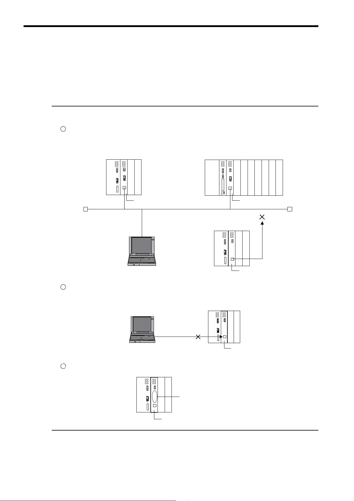
2.1 Overview of 262IF-01 Module
The 262IF-01 has been designed as a communication module for connecting to FL-net via an Ethernet interface
(100BASE-TX or 10BASE-T). FL-net allows this module to be connected to equipment of other manufacturers.
The 262IF-01 supports FL-net (OPCN-2) Version 2.0.
Notes on 262IF-01
The 262IF-01 Module has been designed as a communication module dedicated for use in FL-net. Note the following points:
The 262IF-01 cannot be connected to a regular Ethernet from the 218IF-01 or 218IF-02.
Though the 262IF-01 Module uses a standard Ethernet cable, it does not allow connection for communications based on general-purpose TCP/IP or UDP/IP because it serves only as an FL-net-dedicated module.
MP2300 controller
MP2200 controller
Ethernet
218IF-02218IF-01
MPE720 262IF-01
The MPE720 engineering tool cannot be connected to the 262IF-01 directly.
When connecting the MPE720, separately prepare a module with any of the RS232C, Ethernet, and CP-215 ports for connection.
2-2
No serial port (RS-232C) has been mounted.
Page 22

2
Overview of 262IF-01 Module
2.1.1 Module Specifications
This section provides the specifications of the 262IF-01 Module.
( 1 ) Hardware Specifications
Item Specifications
Name
Model Number
Communication Port
Indicators
Switch
Dimensions (mm)
Mass
262IF-01
JAPMC-CM2303-E
FL-net: 1 port
Module status indicators LED
RUN (green)
TX (green)
FL-net status indicator LED
LINK (orange), 100M (green)
TEST
125 × 95 mm (H × D)
80 g
2.1 Overview of 262IF-01 Module
2.1.1 Module Specifications
ERR (red)
LNK (green)
RX (green)
( 2 ) Transmission Specifications
Ethernet
Transmission
Specifications
FL-net
Specifications
Item Specifications
100BASE-TX 10BASE-T
Interface RJ-45 connector
Compliance Standard
Media Access Mode CSMA/CD
Communication Mode Full duplex/half duplex
Modulation Method Baseband
Transmission Path Type Star topology
Baud Rate
Maximum Number of
Cascade Connections
Transmission Path
Length
(Full length at repeater
usage)
Transmission Media
Maximum Segment
Length
Link Function
Transmission Control
System
IP Address
Port Number
Protocol
Version
IEEE802.3u IEEE802.3i
100 Mbps 10 Mbps
2 layers 4 layers
*1
100 m (205 m max.
Twisted pair cable (UTP)
Category 5 or 5e
Twisted pair cable (STP)
Category 5 or 5e (100 W)
(not possible to fix transmission and communication modes)
Token passing
Class C is used.
192. 168. 250. is used as standard ( indicates a number from 1 to
254 and corresponds to a node number).
For receiving: 3 ports (55000, 55001, and 55002) are used by the system.
For sending: 1 port (55003) is used by the system.
FA link protocol
2.0
) 100 m (500 m max.*1)
Twisted pair cable (UTP)
Category 3, 4, 5, or 5e
Twisted pair cable (STP)
Category 3, 4, 5, or 5e (100 W)
100 m (distance between hub and node at UTP usage)
Support for auto-negotiation
Support for Auto MDI/MDI-X
2-3
Page 23

2.1 Overview of 262IF-01 Module
2.1.1 Module Specifications
Number of Nodes
Cyclic
Transmission
Specifications
Maximum Data Size
Data Exchange
Number of Message
Channels
Engineering
Message
Communication
Transmission
Specifications
Message Service
Number of Transmission
Words
Item Specifications
Up to 254 nodes (at repeater usage)
(262IF-01 I/O can be assigned to 64 nodes only including the self-node.)
Within network:
Area 1 (bit data): 8 kbits
Area 2 (word data): 8 kwords
Per station:
Area 1 + area 2: Area allocation is allowed up to 8 kbits + 8 kwords.
N : N
10
Not supported
Word block read, word block write, network parameter read, network parameter
*3
, stop command*3, start command*3,
write
profile read, transparent message, log data read, log data clear, message loopback
Up to 512 words
(cont’d)
*2
∗ 1. The cable length restriction in repeater (repeater hub or switching hub) usage varies depending on a selected
baud rate.
For repeater or switching hubs, use a commercially available hub for Ethernet. Hubs manufactured by the Japan
Electrical Manufacturer’s Association (JEMA) are recommended.
Restrictions on 100BASE-TX connection
•
Item
Cable length between node and
hub
Cable length between hubs
Number of hubs between nodes
Restrictions on 10BASE-T connection
•
Item
Cable length between node and
hub
Cable length between hubs
Number of hubs between nodes
When Repeater Hub Is
Connected
100 m or less 100 m or less
5 m or less 100 m or less
Up to 2 hubs Not limited
When Repeater Hub Is
Connected
100 m or less 100 m or less
100 m or less 100 m or less
Up to 4 hubs Not limited
When Switching Hub Is
Connected
When Switching Hub Is
Connected
∗ 2. The I/O assignment restriction, which defines that the maximum number of nodes as 64 nodes including the self-
node, is based on MP Series Machine Controller specifications.
∗ 3. A message can be only sent from the client. (Client: Data sending side, Server: Data receiving side)
2-4
Page 24

2
Overview of 262IF-01 Module
( 3 ) Operating Environment Specifications
Item Specifications
Environmental
Conditions
Mechanical
Operating
Conditions
Ambient Operating Temperature
Ambient Storage
Temperature
Ambient Operating Humidity
Ambient Storage
Humidity
Pollution Level Pollution level: 2 (conforming to JIS B3502)
Corrosive Gas There must be no combustible or corrosive gas.
Operating
Altitude
Vibration
Resistance
Shock Resistance
0 to +55 °C
–25 to +85 °C
30% to 95% (with no condensation)
5% to 95% (with no condensation)
2,000 m above sea level or lower
Conforming to JIS B3502
(1) Frequency: 16.7 Hz Vibration strength: 14.7 m/s
(2) Frequency: 10 to 57 Hz Vibration strength: 0.075 mm of single-ampli
(3) Frequency: 57 to 150 Hz
Conforming to JIS B3502
Peak acceleration of 147 m/s
directions
2.1 Overview of 262IF-01 Module
2.1.1 Module Specifications
2
tude
Vibration strength: 9.8 m/s2 of fixed acceleration
2
(15G) twice for 11 ms each in the X, Y, and Z
Electrical
Operating
Conditions
Installation
Requirements
Conforming to EN 61000-6-2, EN 55011 (Group 1 Class A)
Power supply noise (FT noise): ±2 kV min., for one minute
Noise Resistance
Ground Ground to 100Ω max.
Cooling Method Natural cooling
Radiation noise (FT noise): ±1 kV min., for one minute
Ground noise (impulse noise): ±1 kV min., for ten minutes
Electrostatic noise (contact discharge method): ±6 kV min., ten times
2-5
Page 25

2.1 Overview of 262IF-01 Module
262IF-01
ERR
LNK
RX
RUN
TX
-
TEST
ONOFF
LINK
100M
FL-net
(25)
01
FL-net connector
100Base-TX/10Base-T
Status indicators
(LEDs)
Switches
Communication status
indicator (LED)
(included with connector)
Unit: mm
ERR
LNK
RX
RUN
TX
2.1.2 Appearance and Connectors
2.1.2 Appearance and Connectors
The following diagram shows the appearance of the 262IF-01 Module and gives the external dimensions of the connectors.
2.1.3 Status Indicators (LEDs)
2.1.4 Communication Status Indicators (LED) (Included with Ethernet Connector)
The following table shows the status of the 262IF-01 Module shown by the LED indicators.
Indicator Color Meaning When Lit Meaning When Blinking Meaning When Not Lit
RUN Green
ERR Red
LNK Green
TX Green
RX Green
The indicators (LEDs) included with the Ethernet connector show the status of Ethernet communication.
Indicator Color Meaning When Lit Meaning When Not Lit
LINK Yellow
100M Green
FL-net link established. FL-net link not established.
Green: 100 Mbps 10 Mbps or not connected
Operating normally – An error has occurred.
• When RUN is lit:
–
Parameter setting error
• When RUN is not lit:
Normal
Hardware error
Joining FL-net – Not joining FL-net
Sending data – Not sending data
Receiving data – Not receiving data
2-6
Page 26

2
Overview of 262IF-01 Module
2.1.5 Switch Settings
-
TEST
ONOFF
The following table shows the 262IF-01 Module switch settings.
2.1 Overview of 262IF-01 Module
2.1.5 Switch Settings
Label
(Switch No.)
–
(2)
TEST
(1)
Always leave the unused switches (3 and 4) set to OFF.
Name Status Function
–
Operating Mode
Selection
ON
–OFF
OFF
ON
Reserved
OFF
Leave this switch set to OFF.
Fac-
tory
Setting
OFF
2-7
Page 27
2.2 Connection Specifications
LINK
100M
FL-net
LINK
100M
FL-net
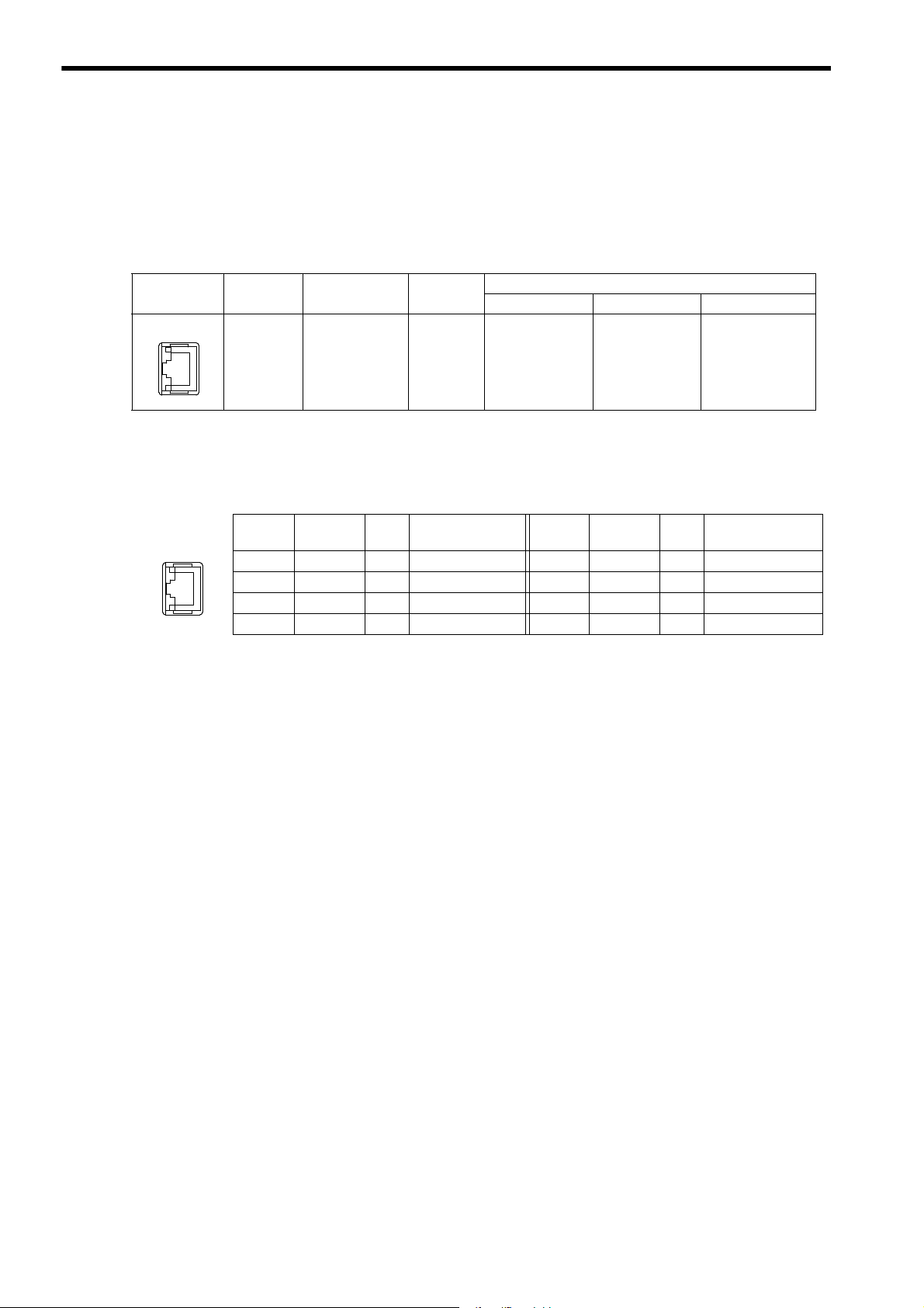
2.2.1 Connector Specifications
2.2 Connection Specifications
2.2.1 Connector Specifications
This section provides the connector specifications for the 262IF-01 Module.
( 1 ) Connector Specifications
Connector
Shape
( 2 ) Connector Pin Arrangement
The connector is used to connect the MP2000 Series Machine Controller to the devices on the FL-net via an FL-net
connection.
Name Connector Name No. of Pins
FL-net FL-net 8
Connector Model
Module Cable Manufacturer
JOG-0001NL
(LED/Pulse
transformer builtin modular jack)
Pulse Engineering
Pin
Number
TXD+ O
1
TXD- O
2
RXD+ I
3
−−
4
2.2.2 Cable Specifications
Yaskawa does not provide FL-net cables. Obtain a commercially available category 5 cross or straight cable.
The AUTO MDI/MDI-X automatically determines cross/straight when using the 262IF-01 Module.
Signal
Name
IO Description
Send data+ 5
Send data- 6
Receive data+ 7
− 8
Pin
Number
Signal
Name
−−
RXD- I
−−
−−
IO Description
−
Receive data-
−
−
2-8
Page 28

2
Overview of 262IF-01 Module
2.3 System Configuration Example
Twisted pair cable (STP category 5)
(Maximum cable length: 100 m)
RJ-45 connector
Hub
PLC from other manufacturer
MP2300
218IF-02 262IF-01
SVB-01
MP2200
218IF-02 262IF-01
LIO-04SVB-01
CPU-02
LIO-04 LIO-04 LIO-01 LIO-01
Twisted pair cable (STP category 5)
(Maximum cable length: 100 m)
AUI cable
(Maximum cable length: 50 m)
Ground terminal
Coaxial cable
(Maximum cable length: 500 m)
Single-port
transceiver
Multi-port
transceiver
Terminator
Hub
MP2300
218IF-02 262IF-01
SVB-01
PLC from other manufacturer
PLC from other manufacturer
The following shows a system configuration example using the 262IF-01.
2.3.1 Small-scale Configuration
A network system of several devices can be constructed through the use of one hub.
2.3 System Configuration Example
2.3.1 Small-scale Configuration
2.3.2 Basic Configuration
A network system of dozens of devices can be constructed by connecting several multi-transceivers and hubs to one
coaxial cable.
2-9
Page 29
2.3 System Configuration Example
MP2200
218IF-02 262IF-01
LIO-04SVB-01
CPU-02
LIO-04 LIO-04 LIO-01 LIO-01
MP2300
218IF-02 262IF-01
SVB-01
Hub
Stackable hub
Twisted pair cable
(STP category 5)
(Maximum cable length: 100 m)
PLC from other
manufacturer
PLC from other
manufacturer
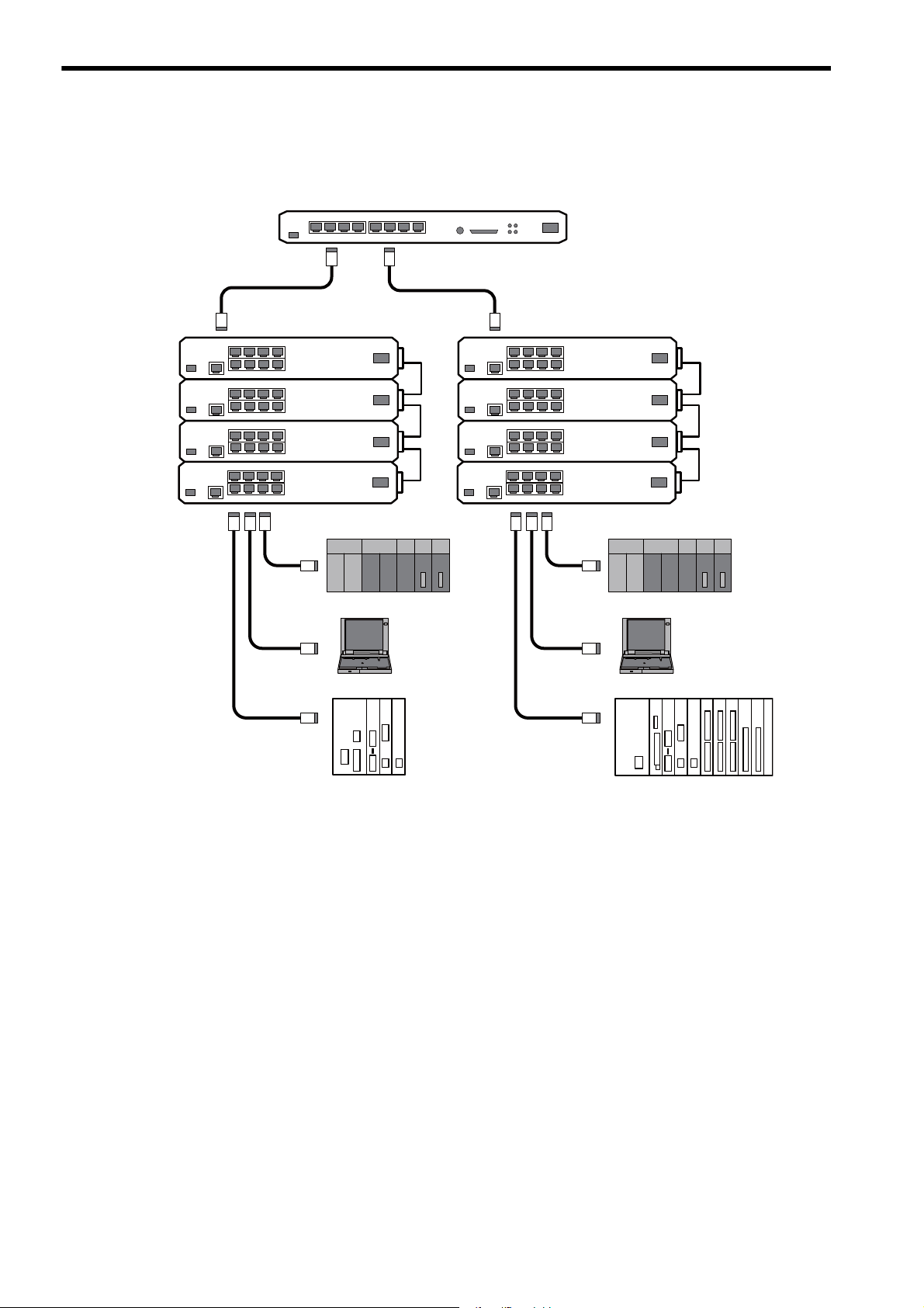
2.3.3 Locally Concentrated Device Configuration
2.3.3 Locally Concentrated Device Configuration
When dozens of devices locally concentrate in a location, a stackable hub can be used to build a network system.
2-10
Page 30

2
Overview of 262IF-01 Module
2.3.4 Long Distant, Locally Distributed Device Configuration
2.3.4 Long Distant, Locally Distributed Device Configuration
When a particular controller is far away in a basic configuration of a network system or there is a high-voltage power
supply or noise source near the network, the network can be divided into two segments that are connected with an optical repeater so that a long distant noise-proof network system can be built.
Optical fiber cable
(Maximum cable length: 2 km)
2.3 System Configuration Example
MP2300
SVB-01
218IF-02 262IF-01
Optical repeater
Hub
Twisted pair cable (STP category 5)
(Maximum cable length: 100 m)
RJ-45 connector
PLC from other manufacturer
Coaxial cable
(Maximum cable length: 500 m)
Optical repeater
AUI cable
(Maximum cable length: 50 m)
2-11
Page 31

3
Mounting and Starting the Module
3
Mounting and Starting the Module
This chapter describes how to connect the 262IF-01 Module and start the system, focusing on
262IF-01 Module mounting, communication process setting, and self-configuration.
3.1 Applicable Machine Controllers and Supported Versions - - - - - - - - - - - - -3-2
3.1.1 Applicable Machine Controllers - - - - - - - - - - - - - - - - - - - - - - - - - - - - - - - - - - - - - - - - 3-2
3.1.2 Supported CPU and MPE720 Versions - - - - - - - - - - - - - - - - - - - - - - - - - - - - - - - - - - 3-2
3.2 Mounting and Removing a Module on Machine Controller - - - - - - - - - - - -3-3
3.2.1 Mounting a 262IF-01 Module - - - - - - - - - - - - - - - - - - - - - - - - - - - - - - - - - - - - - - - - - 3-3
3.2.2 Removing a 262IF-01 Module - - - - - - - - - - - - - - - - - - - - - - - - - - - - - - - - - - - - - - - - - 3-6
3.3 Setting the Communication Manager - - - - - - - - - - - - - - - - - - - - - - - - - - -3-8
3.3.1 Opening the Communication Manager - - - - - - - - - - - - - - - - - - - - - - - - - - - - - - - - - - 3-8
3.3.2 Setting the Communication Manager - - - - - - - - - - - - - - - - - - - - - - - - - - - - - - - - - - - - 3-9
3.4 Self-configuration - - - - - - - - - - - - - - - - - - - - - - - - - - - - - - - - - - - - - - - - 3-19
3.5 Starting the MPE720 and Setting Communication or Network Parameters 3-20
3.4.1 Executing Self-configuration - - - - - - - - - - - - - - - - - - - - - - - - - - - - - - - - - - - - - - - - - 3-19
3.5.1 Starting MPE720 Ver. 6 and Setting Communication - - - - - - - - - - - - - - - - - - - - - - - - 3-20
3.5.2 Starting MPE720 Ver. 5. and Setting the Network - - - - - - - - - - - - - - - - - - - - - - 3-21
3-1
Page 32

3.1 Applicable Machine Controllers and Supported Versions
3.1.1 Applicable Machine Controllers
3.1 Applicable Machine Controllers and Supported Versions
3.1.1 Applicable Machine Controllers
The MP2000 Series Machine Controllers to which the 262IF-01 Modules can be mounted are listed in the following
table.
Max. No. of
Name Model
Base Unit with 100/
MP2200
MP2300 JEPMC-MP2300 2 modules
MP2310 JEPMC-MP2310-E 3 modules
MP2300S JEPMC-MP2300S-E 1 module
MP2100M
MP2500MD
200-VAC input
Base Unit with 24-
VDC input
∗1
JEPMC-BU2200
∗1
JEPMC-BU2210
JAPMC-MC2140 8 modules
JAPMC-MC2540-D 8 modules
Connectable
Modules
8 modules
Remarks
The maximum number of connectable Modules is the
total for the maximum expansion to four Racks.
The 262IF-01 Modules can be mounted to Expansion
Racks (which use the MP2200 Base Unit) connected to
an Expansion Interface Board (MP2100MEX, model:
JAPMC-EX2100) mounted to the Machine Controller.
The maximum number of connectable Modules is the
total for the maximum expansion to three Racks.
∗2
∗2
* 1. One of the following CPU Module is required.
Name Model Remarks
CPU-01
CPU-02
CPU-03
CPU-04
* 2. An EXIOIF Inter-Rack Connection Module (model: JAPMC-EX2200) is required to add Expansion Racks.
The 262IF-01 Modules cannot be mounted on the following MP2000-series Machine Controllers: MP2100, MP2400,
MP2500, MP2500M, and MP2500D.
JAPMC-CP2200 –
JAPMC-CP2210 With one slot for CF card and one USB port
JAPMC-CP2220-E With one slot for CF card and one Ethernet port
JAPMC-CP2230-E With one Ethernet port
3.1.2 Supported CPU and MPE720 Versions
The CPU versions and MPE720 versions of the Machine Controller corresponding to the 262IF-01 Module are listed in
the following table.
Machine Controller
CPU-01 Ver. 2.63 or later Ver. 5.40 or later Ver. 6.06 or later
MP2200
MP2300 Ver. 2.63 or later Ver. 5.40 or later Ver. 6.06 or later
MP2310 Ver. 2.63 or later Ver. 5.40 or later Ver. 6.06 or later
MP2300S Ver. 2.63 or later Ver. 5.40 or later Ver. 6.06 or later
MP2100M Ver. 2.63 or later Ver. 5.40 or later Ver. 6.06 or later
MP2500MD Ver. 2.63 or later Ver. 5.40 or later Ver. 6.06 or later
CPU-02 Ver. 2.63 or later Ver. 5.40 or later Ver. 6.06 or later
CPU-03 Ver. 2.70 or later Ver. 5.50 or later Ver. 6.20 or later
CPU-04 Ver. 2.72 or later Ver. 5.52 or later Ver. 6.22 or later
CPU MPE720 (CPMC-720)
Supported versions
MPE720 Ver.6
(CPMC-770)
3-2
Page 33

3
Mounting and Starting the Module
3.2 Mounting and Removing a Module on Machine Controller
<MP2200/MP2300/MP2200 Base Unit>
Insert a hard thin metal object, such as a coin, into
the notch on the side of the battery cover and open
the cover forward to remove the battery cover.
<MP2310/MP2300S>
Pull the notch on the side of the MP2300S towards
you to remove the battery cover.
3.2.1 Mounting a 262IF-01 Module
3.2 Mounting and Removing a Module on Machine Controller
This section describes mounting and removing a 262IF-01 Module.
3.2.1 Mounting a 262IF-01 Module
Use the following procedure to mount a 262IF-01 Module.
When replacing a 262IF-01 Module, first refer to 3.2.2 Removing a 262IF-01 Module on page 3-6 and remove the
262IF-01 Module that needs to be replaced.
( 1 ) Preparation
1. Backup the Programs.
Save the programs written to the Machine Controller in the personal computer using MPE720.
MPE720 Ver. 5.: Right-click the PLC folder and then select Transfer - All Files - From Controller to
MPE720.
MPE720 Ver. 6.: Open the project file and then select Online - Transfer - Read from Controller.
2. Save in the Flash Memory.
Using the MPE720, save the program data from the Machine Controller in the flash memory.
MPE720 Ver. 5.: Right-click the PLC folder and then select Transfer - Other - Save to Flash.
MPE720 Ver. 6.: Open the project file and then select Online - Transfer - Save to Flash.
3. Remove the Machine Controller and Expansion Rack.
Turn OFF the power supply and remove all the cables connected to the Machine Controller or Expansion Rack
(MP2200 Base Unit). Then, remove the Machine Controller and Expansion Rack from the panel or rack, and
place them where there is sufficient space, such as on a work table.
( 2 ) Removing the Option Cover
If there is an Option Cover attached to the slot in which the 262IF-0 Module is mounted, remove it using the following
procedure.
1. Remove the Battery Cover.
3-3
Page 34

3.2 Mounting and Removing a Module on Machine Controller
3.2.1 Mounting a 262IF-01 Module
2. Remove the Option Cover.
Hold the battery cover with the front facing forward, insert the protrusion on the battery cover into the notch at
the top of the Option Cover, and release the hook on the Option Cover.
Release the hook on the bottom in the same way and remove the Option Cover.
( 3 ) Mounting the 262IF-01 Module
1. Insert the 262IF-01 Module.
Hold onto the top and bottom of the 262IF-01 Module, align the Module with the left side of the guide rail inside
the option slot, and insert the Module straight in.
* If the Module is not inserted on the guide rail, the FG bar on the bottom of the slot may be damaged.
Guide
rail
2. Connect to the Mounting Base Connector.
After inserting the Module all the way to the back, press the Module firmly until it connects securely to the
Mounting Base connected. If the Module is connected securely, the front of the Module should approximately
align with the hooks.
3. Mount the Option Panel.
Insert the hole on the bottom of the option panel into the bottom hook and then securely attach the hole to the top
hook.
3-4
This completes the mounting procedure.
Page 35

3
Mounting and Starting the Module
( 4 ) Procedure after Mounting the Module
1. Connect the Hub.
Connect the hub to the 262IF-01 Module using the Ethernet cable.
Refer to 2.2.2 Cable Specifications on page 2-8 for cables that can be used.
2. Create Module Configurations.
a) Mounting New Modules
Execute self-configuration for each slot in which a 262IF-01 Module was mounted.
Refer to 3.4 Self-configuration on page 3-19 for information on self-configuration.
b) Replacing Modules
Turn OFF the CNFG and INIT DIP switch pins on the Machine Controller and turn ON the power supply.
Once the power has been turned ON, the module configuration can be modified as required.
Refer to 4.1.1 Displaying the Module Configuration Window on page 4-2 for information on the Module config-
uration.
A Communication Module other than the 262IF-01 Module is required for communication between the
Machine Controller and the personal computer running the MPE720. Be sure to mount the Communication
Module and refer to 3.3 Setting the Communication Manager on page 3-8, 3.4 Self-configuration on page 3-
19, and 3.5 Starting the MPE720 and Setting Communication or Network Parameters on page 3-20 to make
the required settings before creating module configurations.
3.2 Mounting and Removing a Module on Machine Controller
3.2.1 Mounting a 262IF-01 Module
3-5
Page 36

3.2 Mounting and Removing a Module on Machine Controller
<MP2200/MP2300/MP2200 Base Unit>
Insert a hard thin metal object, such as a coin, into
the notch on the side of the battery cover and open
the cover forward to remove the battery cover.
<MP2310/MP2300S>
Pull the notch on the side of the MP2300S towards
you to remove the battery cover.
3.2.2 Removing a 262IF-01 Module
3.2.2 Removing a 262IF-01 Module
Use the following procedure to remove a 262IF-01 Module.
( 1 ) Preparation
1. Backup the Programs.
Save the programs written to the Machine Controller in the personal computer using MPE720.
MPE720 Ver. 5.: Right-click the PLC folder and then select Transfer - All Files - From Controller to
MPE720.
MPE720 Ver. 6.: Open the project file and then select Online - Transfer - Read from Controller.
2. Remove the Machine Controller and Expansion Rack.
Turn OFF the power supply and remove all the cables connected to the Machine Controller or Expansion Rack.
Then, remove the Machine Controller and Expansion Rack from the panel or rack, and place them where there is
sufficient space, such as on a work table.
( 2 ) Removing the 262IF-01 Module
1. Remove the Battery Cover.
2. Remove the Option Panel.
Hold the battery cover with the front facing forward, insert the protrusion on the battery cover into the notch at
the top of the Module's option panel, and release the hook on the option panel.
3-6
Release the hook on the bottom in the same way and remove the option panel.
Page 37

3
Mounting and Starting the Module
3.2 Mounting and Removing a Module on Machine Controller
Projection
Notch
Fulcrum
3.2.2 Removing a 262IF-01 Module
3. Remove the 262IF-01 Module from the Mounting Base.
Pull out on the top of the option panel and remove it. A notch can be seen in the I/O Module from the gap in the
panel. Insert the round projection on the battery cover (see the following figure) into the gap in the panel so that
it is inserted in the notch in the Module.
Hold the battery cover as shown in the following figure and use it to gently pull back on the Module, rotating it
indicated by the arrows, to disconnect the Module from the Mounting Base. The Module will move towards you.
4. Pull Out the 262IF-01 Module.
Hold onto the top and bottom of the Module with your fingers and pull the Module straight out. Be sure to hold
onto the edges of the Module. Do not touch the components mounted to the Module.
Place the Module that you removed into the bag that it was delivered in and store it.
Always attach an Option Cover (JEPMC-OP2300) to any unused slot.
3-7
Page 38

3.3 Setting the Communication Manager
Double-click
Communication Manager Icon
3.3.1 Opening the Communication Manager
3.3 Setting the Communication Manager
This section describes the software called the Communication Manager that is used to set the communication method
for engineering communication between the personal computer running the MPE720 and the MP2000 Series Machine
Controller.
Use a Communication Module other than the 262IF-01 Module for communication between the Machine Controller
and the personal computer running the MPE720 and set an appropriate communication method depending on the Module used.
Set the communication conditions with the Communication Manager after the MPE720 Programming Device has been
installed. Once they have been set, it is unnecessary to set from the next startup except when other conditions are to be
added.
3.3.1 Opening the Communication Manager
1. Double-click the Communication Manager Icon in the YE_Applications Folder to start the Communi-
cation Manager. Alternatively, select All Programs - YE-Applications - Communication Manager
under the Windows Start Button.
The Communication Manager Icon will be displayed in the task tray at the right bottom of the window.
2. Double-click the Communication Manager Icon in the task tray and the Communication Manager
Window like the one shown in the step 3 will be displayed.
3. Logical ports for up to 16 channels can be set in the Communication Manager Window. Select and
set unused logical ports from the top.
3-8
Page 39

3
Mounting and Starting the Module
3.3.2 Setting the Communication Manager
Double-click
This section describes the procedure to set the Communication Manager for connecting the MPE720 and MP2000
Series Machine Controller for each type of communication port.
( 1 ) Settings for Serial Communication Port (RS-232C Connection)
These settings are required to perform engineering communication via the serial (RS-232C) port of each Communication Module using the MPE720. Use the following procedure to make the settings.
1. Double-click Logical PT number 1 in the Communication Manager Window.
The Logical Port Setting Dialog Box will appear.
3.3 Setting the Communication Manager
3.3.2 Setting the Communication Manager
2. Select Serial under Port Kind and then click the Detail Button.
The Serial Port Setting Dialog Box will appear.
3. Match the settings under Physical Port to the computer's serial communication port. Leave the other
items on the default settings. Once the settings have been completed and checked, click the OK Button to close the dialog box.
3-9
Page 40

3.3 Setting the Communication Manager
Double-click
3.3.2 Setting the Communication Manager
4. The Logical Port Setting Window will be displayed. Click the OK Button again. The display will return
to the Communication Manager Window. Check that Serial has been allocated to Logical PT number
1.
Saving the Communication Port Settings and Restarting the Communication Manager
Save the communication port settings, and restart the Communication Manager to validate the settings.
1. Select File - Save. A save confirmation window will be displayed. Click the Yes Button to save the
communication port settings.
These settings will be used as the communication port information whenever the Communication Manager is
started.
2. Close the Communication Manager Window and restart to validate the settings.
Select File - Exit to close the Communication Manager Window. A confirmation message will be displayed. Click the Yes Button to close the Communication Manager Window.
3. Double-click the Communication Manager Icon in the YE_Applications Folder to reopen the Com-
munication Manager Window.
3-10
Page 41
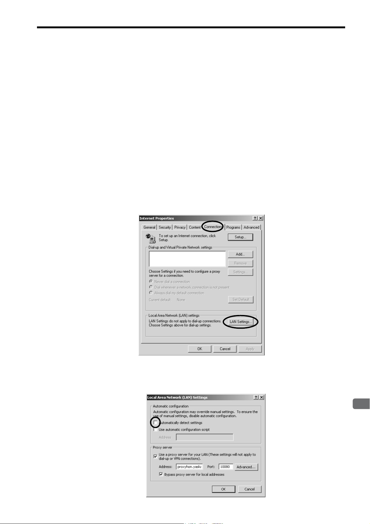
3
Mounting and Starting the Module
3.3 Setting the Communication Manager
3.3.2 Setting the Communication Manager
( 2 ) Setting the Ethernet Communication Port
These settings are required to perform engineering via the 10Base-T communication port (Ethernet) of the 218IF-01
Module. For Ethernet connection, a general-purpose Ethernet board or PCMCIA Ethernet card must be mounted on the
personal computer. Prior to make settings, the IP address of the personal computer must be set.
[ a ] Mounting an Ethernet Card
Mount a general-purpose Ethernet board or PCMCIA Ethernet card on the specified connector of the personal computer. Also, install the driver provided with the Ethernet card.
[ b ] Setting the IP Address
Prior to make settings for Ethernet connection, the IP address of the personal computer must be set. Set the IP address
using the following procedure.
Make the following settings with the LAN cable connected.
1. Click the Windows Start Button and select Settings - Control Panel - Internet Options.
The Internet Properties Dialog Box will be displayed.
2. Click Connections Tab to display the tab page. Click the LAN Settings... Button.
The Local Area Network (LAN) Settings Dialog Box will be displayed.
3. Check that the Automatically detect settings Check Box is cleared, and click the OK Button to close
the dialog box.
3-11
Page 42

3.3 Setting the Communication Manager
3.3.2 Setting the Communication Manager
4. For a computer running the Windows 2000 OS, click the Windows Start Button and select Settings -
Control Panel - Network and Dial-up Connections.
For a computer running the Windows XP OS, click the Windows Start Button and select Settings Control Panel - Network Connections.
On a computer running the Windows 2000 OS, the Network and Dial-up Connections Window will be displayed. On a computer running the Windows XP OS, the Network Connections Window will be displayed.
5. On a computer running the Windows 2000 OS, double-click the Local Area Connection Icon.
On a computer running the Windows XP OS, click Local Area Connection and click Change settings
of this connection in the Network Tasks Field.
Windows 2000
The Local Area Connection Properties Dialog Box will be displayed.
Windows XP
6. Select Internet Protocol (TCP/IP) and click the Properties Button.
3-12
The Internet Protocol (TCP/IP) Properties Dialog Box will be displayed.
7. Click Use the following IP address Option and enter 192 168 1 2 for IP address and 255 255 255 0
for Subnet mask. Then click the OK Button to close the dialog box.
Page 43

3
Mounting and Starting the Module
3.3 Setting the Communication Manager
3.3.2 Setting the Communication Manager
[ c ] Setting the Ethernet Communication Port
1. Double-click Logical Port No. 2 in the Communication Manager Window to display the Logical Port
Setting Dialog Box.
2. Select Ethernet or CP-218 under Port Kind in the Logical Port Setting Dialog Box and click the
Detail Button.
Ethernet and CP-218 set the same communication specifications. Either can be set for Ethernet communica-
tions.
The CP-218 Port Setting Dialog Box will be displayed.
3. Enter the IP address of computer and click OFF for Default. Leave the other items on their default set-
tings. Click the OK Button to close the dialog box.
4. The Logical Port Setting Dialog Box will be displayed again. Click the OK Button to return to the
Communication Manager Window. Check that the CP-218 (Ethernet connection) is assigned to Logi-
cal Port No. 2.
5. Save the settings and restart the Communication Manager.
Refer to
for the procedure.
Saving the Communication Port Settings and Restarting the Communication Manager on page 3-10
3-13
Page 44

3.3 Setting the Communication Manager
3.3.2 Setting the Communication Manager
( 3 ) Setting the Ethernet (LP) Communication Port
These are the optimum settings to perform engineering via the Ethernet communication port of the 218IF-02 Module.
For Ethernet connection, a general-purpose Ethernet board or PCMCIA Ethernet card must be mounted on the personal
computer. Prior to make settings, the IP address of the personal computer must be set.
The Ethernet (LP) communication port can be connected to the 218IFB function of the 218IF-02 Module. It has a
larger engineering message size in comparison to previous Ethernet communication ports, enabling high-speed engineering communication.
The port type and Modules that can be used together are given in the following table.
Port Type Module
218IF-01(218IF) 218IF-02(218IFB)
CP-218 {{
Ethernet {{
Ethernet (LP)
[ a ] Mounting an Ethernet Card
Mount a general-purpose Ethernet board or PCMCIA Ethernet card on the specified connector of the personal computer. Also, install the driver provided with the Ethernet card.
×
{
[ b ] Setting the IP Address
Set the IP address of the person computer using the procedure given in 3.3.2 ( 2 ) [ b ] Setting the IP Address on page
3-11.
[ c ] Setting the Ethernet (LP) Communication Port
1. Double-click Logical Port No. 3 in the Communication Manager Window to display the Logical Port
Setting Dialog Box.
2. Select Ethernet (LP) under Port Kind in the Logical Port Setting Dialog Box and click the Detail But-
ton.
3-14
The CP-218/Ethernet (LP) Port Setting Dialog Box will be displayed.
Page 45

3
Mounting and Starting the Module
3.3 Setting the Communication Manager
3.3.2 Setting the Communication Manager
3. Enter the IP address of computer for the IP Address (First), make sure the rest of the settings are as
shown below, and click the OK Button to close the dialog box.
4. The Logical Port Setting Dialog Box will be displayed again. Click the OK Button to return to the
Communication Manager Window. Check that the Ethernet (LP) is assigned to Logical Port No. 3.
5. Save the settings and restart the Communication Manager.
Refer to
for the procedure.
Saving the Communication Port Settings and Restarting the Communication Manager on page 3-10
3-15
Page 46

3.3 Setting the Communication Manager
3.3.2 Setting the Communication Manager
( 4 ) Setting the CP-215 Communication Port
These settings are required to perform engineering communication via the CP-215 communication port of the 215AIF01 Module using the MPE720.
A CP-215PC/AT card must be mounted on the personal computer and set for the CP-215 connection. Contact your
Yaskawa representative for more information.
[ a ] Setting the CP-215 Communication Port
1. Double-click Logical Port No. 4 in the Communication Manager Window.
The Logical Port Setting Dialog Box will be displayed.
2. Select CP-215 under Port Kind in the Logical Port Setting Dialog Box and click the Detail Button.
The CP-215 Port Setting Dialog Box will be displayed.
3. The Hardware Tab Page will be displayed. Select the type of CP-215PC/AT card mounted on the per-
sonal computer under CP-215 Type.
3-16
4. Set the I/O port number of the mounted CP-215PC/AT card under Physical No. Set the I/O port num-
ber to 1 when using one CP-215PC/AT card. When using two or more cards, allocate ports 2, 3, and 4
sequentially.
Page 47

3
Mounting and Starting the Module
3.3 Setting the Communication Manager
3.3.2 Setting the Communication Manager
5. Click the Parameter Tab in the CP-215 Port Setting Dialog Box. Set the following items.
Local Station Address
Local Network Address
Max Connect Station
Token Round Time
Setting
MEMOBUS Response
Watch Time
: Set the MPE720 (personal computer) station number to between 1 and 64.
: Set the number of the network to which the MPE720 (personal computer) is connected to
between 1 and 254. If there is only one network segment, set 1.
: Set the number of CP-215 network stations.
: This is the target time from when each station receives the token until the next time the same
station receives the token. Set 100.
: This is the time from when a message is sent until the response is received. Set 255.
Leave the other items set to their default values.
6. Click the Channel Tab in the CP-215 Port Setting Dialog Box. Select 2 under Panel Command
Channel. Leave the other items set to their default values and click the OK Button to close the dialog
box.
3-17
Page 48

3.3 Setting the Communication Manager
3.3.2 Setting the Communication Manager
7. The Logical Port Setting Dialog Box will be displayed again. Click the OK Button to return to the
Communication Manager Window. Check that CP-215 (MPLINK/CP-215 connection) is assigned to
the Logical Port No. 4.
8. Save the settings and restart the Communication Manager.
Refer to
for the procedure.
Saving the Communication Port Settings and Restarting the Communication Manager on page 3-10
3-18
Page 49

3
Mounting and Starting the Module
3.4.1 Executing Self-configuration
3.4 Self-configuration
The self-configuration function automatically detects the Option Modules connected to the Machine Controller and
automatically generates the files for the Module configuration definitions and the detailed definition of each Module.
Executing self-configuration will greatly reduce the system startup procedure.
After executing self-configuration, always save data to flash memory so that the results of self-configuration
are saved in the Machine Controller.
3.4.1 Executing Self-configuration
The methods used to execute self-configuration are described below.
( 1 ) Setting the CNFG DIP Switch Pin and Cycling Power (MP2200/MP2300/MP2310/
MP2300S)
Self-configuration can be executed by turning ON the CNFG DIP switch pin on the Machine Controller and turning the
power OFF and then ON again. The result will depend on the setting of the INIT DIP switch pin.
3.4 Self-configuration
CNFG INIT Result
ON ON
ON OFF
The DIP switch is not normally used for the MP2100M/MP2500MD. For these Machine Controllers, use the MPE720
as described next.
( 2 ) Using the MPE720 (MP2100M/MP2500MD)
Start the MPE720, start the Engineering Manager, and then select Order - Self Configure All Modules from the Main
Menu. Alternatively, select the Module for which self-configuration is to be executed in the Module Configuration
Window, and then select
Refer to 4.1.1 Displaying the Module Configuration Window on page 4-2 for the procedure to display the Module
Configuration Window.
The result depends on the command that is used, as described below.
Self-configuration for
all Modules
Module Self-configuration
• The Module configuration definitions are updated.
• The default allocations are made for all of the Modules that are detected.
• The Module configuration definitions are updated.
• The definitions for any Modules for which there are already definitions are not changed.
• The default values are allocated in the definitions for any new Modules that are detected.
Order - Module Self-configuration from the Main Menu.
Command Result
• The Module configuration definitions are updated.
• The definitions for any Modules for which there are already definitions are not changed.
• The default values are allocated in the definitions for any new Modules that are detected.
• Definitions are allocated only for the selected Module.
• The definitions for any Modules for which there are already definitions are not changed.
• The default values are allocated in the definitions for any new Modules that are detected.
3-19
Page 50

3.5 Starting the MPE720 and Setting Communication or Network Parameters
3.5.1 Starting MPE720 Ver. 6 and Setting Communication
3.5 Starting the MPE720 and Setting Communication or Network
Parameters
This section describes how to start the MPE720 and set the communication parameters in the project file (MPE720 Ver.
6) or the network parameters in the PLC folder (MPE720 Ver.5.).
3.5.1 Starting MPE720 Ver. 6 and Setting Communication
This section describes how to start the MPE720 and set the communication parameters in the object file.
Disconnect the Machine Controller when setting the parameters.
Create the object file in advance.
1. Select Online - Communications Setting from the Main Menu. Alternatively, select Controller -
Communications Setting (or Project - Communications Setting) in the Start Window.
The Communications Setting Dialog Box will be displayed.
2. Select the logical port number to use to connect the Machine Controller and click the Setting Button.
Settings for the logical port numbers are made with the Communication Manager. Refer to 3.3 Setting the
Communication Manager on page 3-8 for the Communication Manager setting procedure.
Communication will be set and the dialog box will close.
The Connection and Setting Buttons will be disabled while the Machine Controller is connected.
3-20
Page 51

3
Mounting and Starting the Module
3.5 Starting the MPE720 and Setting Communication or Network Parameters
3.5.2 Starting MPE720 Ver. 5. and Setting the Network
3.5.2 Starting MPE720 Ver. 5. and Setting the Network
This section describes how to start the MPE720 and set the network parameters in the PLC folder.
Create the PLC folder in advance.
1. Open the YE_Applications Folder and double-click the MPE720 Icon.
Alternatively, select MPE720 from the Start Menu.
The procedure to select the network depends on the operating system.
The MPE720 will start and the File Manager Window will be displayed.
2. Open the root, group, and then order folder, right-click the desired PLC folder, and select Properties
from the pop-up menu that is displayed.
The Controller Configuration Dialog Box will be displayed.
3-21
Page 52

3.5 Starting the MPE720 and Setting Communication or Network Parameters
3.5.2 Starting MPE720 Ver. 5. and Setting the Network
3. Click the Network Tab and select Ye s for OnLine.
Fields will be displayed for the logical port number, unit number, and route so that they can be set.
4. For Logical Port No. (Device Type), set the logical port number to use from the logical port numbers
that were set with the Communication Manager.
The contents display on the tab page may change depending on the port that is selected.
The devices types indicate the following connections: CP-217 indicates an RS-232C connection (serial port),
CP-218 indicates an Ethernet connection, and CP-215 indicates a connection through a CP-215PC/AT card
mounted on the personal computer.
5. <RS-232C Connection>
Leave all other settings on their default values and click the OK Button.
3-22
Page 53

3
Mounting and Starting the Module
3.5 Starting the MPE720 and Setting Communication or Network Parameters
3.5.2 Starting MPE720 Ver. 5. and Setting the Network
<Ethernet Connection>
Enter the IP address of the personal computer and click the OK Button.
<CP-215 Connection>
Enter the network number and station number and click the OK Button.
Enter the same network number and station number as the ones set with the Communication Manager.
6. A confirmation dialog box will be displayed. Click the Yes Button. This completes selecting the logical
port.
These transmission definition settings are required for each Communication Module. Refer to Machine Controller
MP2000 Series Communication Module User’s Manual (Manual No.: SIEPC88070004) for details on the transmission
definition settings
.
3-23
Page 54

4
FL-net Transmission Definition
4
FL-net Transmission Definition
For 262IF-01 FL-net communication using a MP2000 Series Machine Controller, an FL-net
transmission definition file must be created. This chapter discusses how to make an FL-net
transmission definition on the MPE720 screen.
4.1 Displaying the FL-net Transmission Configuration Window - - - - - - - - - - - -4-2
4.1.1 Displaying the Module Configuration Window - - - - - - - - - - - - - - - - - - - - - - - - - - - - - - 4-2
4.1.2 Displaying the FL-net Transmission Configuration Window from the Module
Configuration Window - - - - - - - - - - - - - - - - - - - - - - - - - - - - - - - - - - - - - - - - - - - - - - 4-3
4.2 FL-net Transmission Definition - - - - - - - - - - - - - - - - - - - - - - - - - - - - - - - -4-4
4.2.1 Transmission Parameters Tab Page - - - - - - - - - - - - - - - - - - - - - - - - - - - - - - - - - - - - 4-4
4.2.2 Link Assignment Tab Page - - - - - - - - - - - - - - - - - - - - - - - - - - - - - - - - - - - - - - - - - - - 4-6
4.2.3 Link Status Tab Page - - - - - - - - - - - - - - - - - - - - - - - - - - - - - - - - - - - - - - - - - - - - - - - 4-9
4.2.4 Status Detail Window - - - - - - - - - - - - - - - - - - - - - - - - - - - - - - - - - - - - - - - - - - - - - - 4-10
4.2.5 Status Tab Page - - - - - - - - - - - - - - - - - - - - - - - - - - - - - - - - - - - - - - - - - - - - - - - - - 4-12
4.2.6 Network Configuration Window - - - - - - - - - - - - - - - - - - - - - - - - - - - - - - - - - - - - - - - 4-13
4.2.7 Saving FL-net Transmission Definitions - - - - - - - - - - - - - - - - - - - - - - - - - - - - - - - - - 4-14
4-1
Page 55

4.1 Displaying the FL-net Transmission Configuration Window
4.1.1 Displaying the Module Configuration Window
4.1 Displaying the FL-net Transmission Configuration Window
This section describes how to open the Module Configuration Window from the MPE720, open the Transmission
Configuration Window from the Module Configuration Window, and set the transmission definitions for the FL-net
Module.
4.1.1 Displaying the Module Configuration Window
Use the following procedure to display the Module Configuration Window.
( 1 ) MPE720 Ver. 6
1. Start the MPE720 on the personal computer connected to the Machine Controller and open the project
file.
For information on starting the MPE720, refer to Machine Controller MPE720 Programming Device Ver. 6 User's
Manual (Manual No.: SIEPC88070030).
2. Select Setup - Module configuration in the Launcher, or double-click the Module configuration Icon
in the system subprogram.
The Engineering Manager will be started and the Module Configuration Window will be displayed (see next
page).
( 2 ) MPE720 Ver. 5
1. Start the MPE720 on the personal computer connected to the Machine Controller and use the File Man-
ager to log in and go online with the application for the Machine Controller.
For information on starting the MPE720 and logging on, refer to MPE720 Software for Programming Device
User's Manual (Manual No.: SIEPC88070005).
2. Double-click the Module Configuration Icon in the Definition Folder.
The Engineering Manager will be started and the Module Configuration Window will be displayed (see next
page).
4-2
Page 56

4
FL-net Transmission Definition
4.1 Displaying the FL-net Transmission Configuration Window
<MP2300/MP2310/MP2300S Module Configuration Window>
Click.
1
Double-click.
2
<MP2100M/MP2200/MP2500MD Module Configuration Window>
Click.
1
Double-click.
2
4.1.2 Displaying the FL-net Transmission Configuration Window from the Module Configuration Window
4.1.2 Displaying the FL-net Transmission Configuration Window
from the Module Configuration Window
As the result of executing self-configuration, all Option Modules connected to the Machine Controller will be displayed in the Controller Area of the Module Configuration Window. (Refer to
page 3-19
.)
In the Controller Area, select the 262IF-01 cell, and then double-click the slot number cell for FL-net in the Module
Details Area. The FL-net Transmission Configuration Window (see next page) will be displayed.
3.4.1 Executing Self-configuration on
In Online Mode, the FL-net transmission definitions data saved in the Machine Controller are displayed. In Offline
Mode, the definitions data saved in the personal computer on which MPE720 is running is displayed.
The FL-net Transmission Configuration Window is composed of four tab pages: Transmission Parameters, Link
Assignment, Link Status, and Status. These tab pages are used to set the definitions and monitor the settings.
If the Transmission Configuration Window is being opened for the first time, a “new file” message box will be dis-
played and the FL-net Transmission Configuration Window will be displayed when the OK Button is clicked.
4-3
Page 57

4.2 FL-net Transmission Definition
1
2
3
4
5
6
Configuration
information
1
Field No. 4: Module node numbers 1 to 254
Field No. 2: 0 to 255
Field No. 1: 192 to 223
Field No. 3: 0 to 255
234
4.2.1 Transmission Parameters Tab Page
4.2 FL-net Transmission Definition
4.2.1 Transmission Parameters Tab Page
Set the parameters required for FL-net communication. The following gives a detailed description.
Configuration Information
The 262IF-01 configuration information is displayed. This configuration information is the same as the information
displayed in the Module Details Area in the Module Configuration Window.
RACK#: The rack number of the rack in which the 262IF-01 is defined.
Slot#: The slot number of the slot in which the 262IF-01 is defined.
CIR#: The circuit number of the Ethernet port on the 262IF-01.
When the MSG-SND or MSG-RCV function is used, set the circuit number displayed here for CIR# (circuit
number).
Setting the Transmission Parameters
IP Address
Set the IP address of the local node. The last digit is used as a module node number.
There are four 8-bit fields delimited by periods (.). Input a decimal number for each field.
Do not use the same address as another node. If a duplicate IP address is entered, undetect will be selected
as Bit 7 Address overlapping detection in the Status Detail Window (refer to page 4-10), resulting in a dis-
abled network connection.
Subnet Mask
Set the subnet mask for the IP address of the local node.
Since “255.255.255.0” is automatically set in FL-net, use this default value.
Token monitoring time
Set the monitoring time in units of ms from when the node acquires the token until the node issues a token.
This time can be set in a range from 1 to 255 (ms).
Minimum permissible frame interval
4-4
Set the time in units of 100 μs from when the local node receives a token from a remote node until the local node
sends a frame.
This time can be set in a range from 0 to 50 (0-5 ms).
Page 58

4
FL-net Transmission Definition
4.2 FL-net Transmission Definition
5
6
4.2.1 Transmission Parameters Tab Page
Common memory area 1 size
Make this setting to assign registers to respective areas 1 and 2 in the entire common memory within an I/O
register range assigned in the Module Configuration Window. The 1 size of common memory area beginning
with an I/O leading register number is assigned for area 1, and the remaining range (from [I/O leading register
number + 1 size of common memory area] to I/O ending register number) is assigned for area 2.
Set the size in units of words within a range from 0 to 200H (0 to 512 words).
The maximum value of the area 1 size is 200H and that of the area 2 size is 2000H.
The default value is 200(H). When reducing this value, reduce the I/O register range in advance on the Module
Configuration Window by the value to be reduced (or by the value greater than the value to be
reduced).When an attempt is made to reduce a common memory area 1 range without this operation, an error
will occur.
<Example>
To set common memory area 1 size to 100(H) when an I/O leading register number is 0402 and an I/O ending
register number is 2601, the I/O register number must be reduced to 2501 or less or the I/O leading register
number must be set to 0302 or more.
When the default value is changed, an error occurs for the following reasons.
Because the common memory area 1 size is 200H and the I/O register size is 2200H by default, the default
common memory area 2 size (I/O register size - common memory area 1 size) is 2000H (maximum value of
common memory area 2 size). When the common memory area 1 size is less than the default value of 200, an
error will occur because the common memory area 2 size exceeds the maximum value of 2000H.
For common memory and areas 1 and 2, refer to 5.3.1 ( 4 ) Common Memory and Areas 1 and 2 on page 5-9
and 5.3.1 ( 5 ) Assignment of I/O Register and Common Memory on page 5-10.
For relationship between common memory assigned to the I/O register and common memory assigned to each
node, refer to 4.2.2 ( 3 ) Link Assignment Setting Example and Common Memory Assignment Image on page
4-8.
Node name
Enter a name of the local node up to ten characters.
Terminology: Minimum Permissible Frame Interval
FL-net shares this minimum permissible frame interval in the network. Each node calculates and updates the maximum value of
minimum permissible frame intervals set by nodes joined to the network each time a node joins or leaves the network.
4-5
Page 59

4.2 FL-net Transmission Definition
3
4
5
6
7 8 9 10
11
12 13
1
2
1
23545
6
4.2.2 Link Assignment Tab Page
4.2.2 Link Assignment Tab Page
( 1 ) Details of the Link Assignment Tab Page
Set link assignment for each node in FL-net on the Link Assignment Tab Page.
Information on common memory areas 1 and 2 of each node, which has been received through cyclic transmission, is
stored in the registers of areas 1 and 2 of each node set here. In addition, information on common memory areas 1and 2
of a local node is broadcast to other nodes on FL-net when it holds the token.
Information on common memory areas 1 and 2 of other nodes, which is to be assigned here, must be identical to
that assigned to the nodes for themselves. To assign other nodes, assignment information must be obtained in
advance or the Network Configuration Window (refer to page 4-13) must be opened with the node joined to FL-net
to confirm the node information.
For the relationship between common memory area assignments to nodes and I/O registers, refer to 4.2.2 ( 3 ) Link
Assignment Setting Example and Common Memory Assignment Image on page 4-8.
The following gives a detailed description.
Common Memory Area 1
Displays the area 1 address range determined according to the setting of the transmission parameter Common
memory area 1 size on the Transmission Parameters Tab Page. This range cannot be changed.
Common Memory Area 2
Displays the area 2 address range determined according to the setting of the transmission parameter Common
memory area 1 size on the Transmission Parameters Tab Page. This range cannot be changed.
Local Node
When a node number ( ) is identical to the least significant digit in IP address on the Transmission Parameters Tab Page, “**” is displayed here to indicate a local node.
No.
Displays the interface number for CPU (fixed).
Node Number
Enter the node number (least significant digit in IP address) of a node to be assigned.
This value can be set in a range from 1 to 254. Note that the setting value must be unique.
Area 1 Common memory
Set the I/O leading register address of FL-net common memory area 1 of a target node for assignment in units of
words. This value can be set in a range from 0 to 511.
4-6
Page 60

4
FL-net Transmission Definition
4.2 FL-net Transmission Definition
789
101112
13
4.2.2 Link Assignment Tab Page
Size (area 1 size)
Set the assignment size of FL-net common memory area 1 of a target node for assignment in units of words. This
value can be set in a range from 0 to 512.
I/O area REG-No
Displays the address range of corresponding I/O registers according to the common memory area 1 assignment.
“OW( to )” is displayed for the local node and “IW( to )” for other nodes.
Area 2 Common memory
Set the I/O leading register address of FL-net common memory area 2 of a target node for assignment in units of
words. This value can be set in a range from 0 to 8191.
Size (area 2 size)
Set the assignment size of FL-net common memory area 2 of a target node for assignment in units of words. This
value can be set in a range from 0 to 8192.
I/O area REG-No
Displays the address range of corresponding I/O registers according to the common memory area 2 assignment.
“OW( to )” is displayed for the local node and “IW( to )” for other nodes.
SCAN
Set the refresh cycle of the I/O area assigned for each node to “High” or “Low.”
Comment
Enter each node name up to ten characters.
( 2 ) Link Assignment Deletion
Link assignments can be deleted in units of lines according to the following procedure.
Care should be taken for assignment deletion because the deleted assignment cannot be restored.
1. Click any cell on an assignment line to be deleted from the Link Assignment Tab Page.
2. Select Edit-Assignment Delete from the Main Menu.
The selected assignment line will be deleted.
4-7
Page 61

4.2 FL-net Transmission Definition
Set by Transmission Parameters
Tab Page
0000
0004
0010
0012
0511
IW1000
OW1004
IW100A
IW100C
IW1200
OW123C
IW1246
IW1264
IW31FF
6 words
0000
0060
0100
0070
8191
Area 1
Area 2
10 words
㧦Local node (OW register)
㧦Other node (IW register)
FL-net common memory
(Set by Link Assignment
Tab Page)
Node number 1 (input)
Node number 1 (input)
Node number 2 (output)
Node number 2 (output)
Node number 4 (input)
Node number 1 (input)
Node number 2 (output)
Node number 4 (input)
Node number 1 (input)
Node number 2 (output)
Node number 4 (input)
Node number 4 (input)
Common memory area 1 size
(variable in a range from
0 to 200H)
Common memory area 2 size (variable in a range from 0 to 2200H)
(I/O ending register number − common memory area 1 size)
CPU Module I/O register
4.2.2 Link Assignment Tab Page
( 3 ) Link Assignment Setting Example and Common Memory Assignment Image
The following figure shows a link assignment example and a common memory assignment image.
Because areas 1 and 2 in the local node are used only for sending, they work as output registers (OW). Because areas 1
and 2 in other nodes are used only for reception, they work as input registers (IW).
4-8
Page 62

4
FL-net Transmission Definition
4.2.3 Link Status Tab Page
1 2 3 4 5 6
123
4
656
6
7
The FL-net link status can be monitored on the Link Status Tab Page.
The following gives a detailed description.
4.2 FL-net Transmission Definition
4.2.3 Link Status Tab Page
Local Node
Displays “**” as a local node number.
No.
Dispalys the Interface number for CPU (fixed).
Node Number
Dispalys the node number of each node set in the Link Assignment Tab Page.
FA link
Displays the current status regarding whether each node set in the Link Assignment Tab Page has joined or left
FL-net as “Join” or “Leave.”
This information is bit 0 link information of the FL-net link information. The other information can be referenced
on the Status Detail Window displayed by clicking the Detail Button ( ).
High-ranking layer (Upper layer RUN/STOP)
Displays the bit 7 RUN/STOP status of the FL-net upper layer status as “RUN” or “Stop.” The other information
can be referenced on the Status De tail Window displayed by clicking the Detail Button ( ).
Detail Button
Click this button, and the Status Detail Window will be displayed to show information such as FA Lin k and
High-ranking layer status of a selected node with a code as a bitwise explanation.
Comment
Displays each node comment set in the Comment of the Link Assignment Tab Page.
4-9
Page 63

4.2 FL-net Transmission Definition
2
3
4
5
6
7
8
9
10
11
12
13
14
15
16
17
1
1234567
8
4.2.4 Status Detail Window
4.2.4 Status Detail Window
This window is displayed by clicking the Detail Button on the Link Status Tab Page.
The FL-net link information, upper layer status, and token monitoring time of the selected node are displayed.
The following gives a detailed description.
Node (Node number)
Displays a node number selected on the Link Status Tab Page.
FA Link
Status
Displays a status code of the link status of the selected node.
Bit 0: Node status on in-ring/out-ring (Joined/not joined)
Displays whether a selected node has joined or left FL-net.
ON = In-ring (joined), OFF = Out-ring (not joined)
Bit 1: Communication invalidity
Displays whether the communication disabled status of a selected node has been detected.
ON = Detected, OFF = Not detected
• Bits 2 and 3: Reserve
Reserved by system. Always set to OFF.
Bit 4: Upper layer operation signal error
Displays whether there is an operation signal error in the upper layer.
ON = Error, OFF = Normal
Bit 5: Common memory data validity notification
Displays whether common memory data in the selected node is valid.
ON = Enable (valid), OFF = Disable (invalid)
4-10
Page 64

4
FL-net Transmission Definition
4.2 FL-net Transmission Definition
91011121314151617
4.2.4 Status Detail Window
Bit 6: Common memory setting completion
Displays whether the settings for common memory areas 1 and 2 have been completed on the Link Assignment
Tab Page.
ON = Complete, OFF = Incomplete
Bit 7: Address overlapping detection
Displays whether duplication of the I/O area address in the common memory has been detected.
ON = Detect (duplicate), OFF = Undetect
High-ranking Layer Status (Status of upper layer)
Status
Displays a status code of the upper layer status of the selected node.
Bit 0 to B: U_ERR_CODE
Not used.
Bit C: Reserve
Reserved by system. Always set to OFF.
Bit D: WARNING
Not used.
Bit E: ALARM
Not used.
Bit F: RUN/STOP
Displays an operating status of the upper layer.
ON = RUN (operating), OFF = STOP (stopped)
Network Information
Token monitoring time
Displays the network monitoring time set on the Transmission Parameter Tab Page.
4-11
Page 65

4.2 FL-net Transmission Definition
1
2
3
4
5
6
7
8
1234567
8
4.2.5 Status Tab Page
4.2.5 Status Tab Page
The FL-net status can be monitored on the Stat us Tab Page.
The display contents are updated as needed.
The following gives a detailed description.
Status of local node
Displays the local node status in the lower-place two digits of a four-digit hexadecimal number.
Bit 0 to 2: Reserved (Not used. Always set to 0.)
Bit 3: Token monitoring time error (1: End of time period set in token monitoring timer, 0: Normal)
Bit 4: Common memory setting range error (1: Error, 0: Normal)
Bit 5: Frame waiting status (1: Wait for frame reception from other node, 0: Frame wait reset)
Bit 6: Duplicated node number detection (1: Duplicated number detected, 0: Normal)
Bit 7: Joined to network (1: Joined, 0: Not joined)
Bit 8 to Bit F: Reserved (Not used. Always set to 0.)
Minimum permissible frame interval
Displays the minimum permissible frame interval set on the Transmission Parameters Tab page. (Unit: ms)
Refresh cycle measuring time
Displays the refresh cycle time measurement value (current value). (Unit: ms)
Refresh cycle time (max.)
Displays the maximum refresh cycle time. (Unit: ms)
Refresh cycle time (min.)
Displays the minimum refresh cycle time. (Unit: ms)
Token monitoring time
Displays the token monitoring time set on the Transmission Parameters Tab Page. (Unit: ms)
4-12
Vendor code
Displays the vendor name “YASKAWA.”
Manufacturer model name
Displays the first ten bytes, “JAPMC-CM23,” of “JAMPMC-CM2303-E” in the 262IF-01 model number.
Page 66

4
FL-net Transmission Definition
4.2.6 Network Configuration Window
9
1 2 3 4 5 6 7 8
10
1
234
567
The status of all nodes connected to FL-net can be monitored on the Network Configuration Window.
( 1 ) Displaying the Network Configuration Window and
Searching for the Statuses of the Connected Nodes
Select Edit - Network configuration from the Main Menu to display the Network Configuration Window.
Network configuration under the Edit menu is enabled only in Online Mode.
Click the Search Start Button on the Network Configuration Window to display the statuses of all nodes connected
to FL-net.
Click the Close Button to close the Network Configuration Window.
( 2 ) Displayed Contents of the Network Configuration Window
4.2 FL-net Transmission Definition
4.2.6 Network Configuration Window
The following gives a detailed description.
Node Number
Displays the node number of FL-net equipment.
Area 1 Common memory
Displays the address number of common memory area 1 occupied by the node.
Size (area 1 size)
Displays the register size of common memory area 1 occupied by the node in units of words.
Area 2 Common memory
Displays the address number of common memory area 2 occupied by the node.
Size (area 2 size)
Displays the register size of common memory area 2 occupied by the node in units of words.
FA link
Displays the current status whether the node joins or leaves FL-net as “Join” or “Leave.”
High-ranking layer (Upper layer RUN/STOP)
Displays the bit 7 RUN/STOP status of the FL-net upper layer status as “RUN” or “Stop.”
4-13
Page 67

4.2 FL-net Transmission Definition
8910
4.2.7 Saving FL-net Transmission Definitions
Details Button
Clicking this button displays the Status Detail Window so that the FA link or upper layer status of the node can
be monitored.
For the Status Detail Window, refer to 4.2.4 Status Detail Window on page 4-10.
Search Start Button
Clicking this button starts a status search of all nodes connected to FL-net and updates status information.
Close Button
Clicking this button closes the Network Configuration Window.
4.2.7 Saving FL-net Transmission Definitions
When an FL-net transmission definition has been set or changed, select File - Save & Save into flash memory from the
Main Menu to save the FL-net transmission definitions.
4-14
Page 68

5
Details of FL-net
5
Details of FL-net
This chapter describes the FL-net transmission system in detail.
5.1 Ethernet Segment Configuration Example - - - - - - - - - - - - - - - - - - - - - - - -5-2
5.1.1 10BASE5 System - - - - - - - - - - - - - - - - - - - - - - - - - - - - - - - - - - - - - - - - - - - - - - - - - 5-2
5.1.2 10BASE-T System - - - - - - - - - - - - - - - - - - - - - - - - - - - - - - - - - - - - - - - - - - - - - - - - 5-2
5.1.3 100BASE-TX system - - - - - - - - - - - - - - - - - - - - - - - - - - - - - - - - - - - - - - - - - - - - - - - 5-3
5.1.4 Ethernet IP Address - - - - - - - - - - - - - - - - - - - - - - - - - - - - - - - - - - - - - - - - - - - - - - - 5-4
5.2 About FL-net - - - - - - - - - - - - - - - - - - - - - - - - - - - - - - - - - - - - - - - - - - - -5-5
5.2.1 FL-net Overview - - - - - - - - - - - - - - - - - - - - - - - - - - - - - - - - - - - - - - - - - - - - - - - - - - 5-5
5.3 FL-net Data Communication - - - - - - - - - - - - - - - - - - - - - - - - - - - - - - - - -5-9
5.3.1 Cyclic Transmission - - - - - - - - - - - - - - - - - - - - - - - - - - - - - - - - - - - - - - - - - - - - - - - - 5-9
5.3.2 Message Transmission - - - - - - - - - - - - - - - - - - - - - - - - - - - - - - - - - - - - - - - - - - - - 5-12
5.3.3 Details of Supported Messages - - - - - - - - - - - - - - - - - - - - - - - - - - - - - - - - - - - - - - 5-14
5-1
Page 69

5.1 Ethernet Segment Configuration Example
Segment (maximum length: 500 m)
NNNNN
N
㧦Coaxial cable
㧦Transceiver cable (AUI cable)
㧦Single-port transceiver
㧦Multi-port transceiver
㧦Node
㧦Terminator
NNN
Repeater hub
N
NN
N
㧦Coaxial cable
㧦Transceiver cable (AUI cable)
㧦Twisted pair cable (10BASE-T)
N
Segment (maximum length: 500 m)
㧦Node
㧦Terminator
5.1.1 10BASE5 System
5.1 Ethernet Segment Configuration Example
FL-net (OPCN-2) is an FA control network that employs Ethernet as a communication medium (physical level, data
link) between FA controllers.
When the baud rate is 10 Mbps, the Ethernet physical layer supports five transmission methods: 10BASE5, 10BASE2,
10BASE-T, 10BASE-F, and 10BROAD36. When the baud rate is 100 Mbps, it supports four transmission methods:
100ASE-T2, 100BASE-T4, 100BASE-TX, and 100BASE-FX.
FL-net recommends the use of 10BASE5, 10BASE2, 10BASE-T, 100BASE-TX, and 100BASE-FX.
The following shows segment configuration examples for 10BASE5, 10BASE-T, and 100BASE-TX.
5.1.1 10BASE5 System
As shown in the following figure, the basic configuration consists of a 500-m (maximum length) coaxial cable and
nodes connected to the cable. This basic configuration is called a segment and one segment comprises a maximum of
100 nodes.
Each node is connected to the coaxial cable via a transceiver cable (AUI cable) and a transceiver.
There are two types of transceivers: a single-port transceiver that allows the connection of only one transceiver cable
(AUI cable) and a multi-port transceiver that allows the connection of multiple transceiver cables.
5-2
5.1.2 10BASE-T System
A hub (repeater hub) can be connected to a transceiver cable (AUI cable) to allow the connection of multiple nodes.
Use a twisted pair cable (10BASE-T) between the hub and node.
The maximum length between the hub and node is 100 m.
Page 70

5
Details of FL-net
5.1.3 100BASE-TX system
( 1 ) Example Using a Switching Hub
The system is generally called “Fast Ethernet,” supporting a baud rate of 100 Mbps. Generally, the 100BASE-TX system employs a twisted pair cable for connection via a switching hub. The maximum length of each twisted pair cable is
100 m and is identical to that of 10BAESE-T system.
The switching hub serves as a bridge. When segments are connected via the switching hub, the cascade connection
count of the repeater is cleared and cascade restrictions are removed unlike with a repeater hub.
In addition, some switching hubs support multiple baud rates such as 100BASE-TX and 10BASE-T. The use of these
switching hubs enables 100BASE-TX and 10BASE-T equipment in the same system.
In this case, however, care should be taken because the switching hub causes a greater delay than the repeater hub.
5.1 Ethernet Segment Configuration Example
5.1.3 100BASE-TX system
Switching hub
Switching hub
NNN
N
Segment Segment
Switching hub
NN N
㧦Twisted pair cable
㧔100BASE-TX㧕
㧦Node
( 2 ) Example Using a Repeater Hub
When a 100BASE-TX repeater hub is used, it is subject to cascade connection restrictions. When a Class II repeater
hub has been used, a maximum of two cascade connections can be made for the repeater hub. In this case, however, the
maximum distance between repeater hubs is 5 m.
The following figure shows a system configuration example.
Repeater hub
NN N
N
Repeater hub
NN N
㧦Twisted pair cable
㧔100BASE-TX㧕
㧦Node
5-3
Page 71

5.1 Ethernet Segment Configuration Example
5.1.4 Ethernet IP Address
5.1.4 Ethernet IP Address
Generally, UDP/ID employs a 32-bit logical address called as an “IP address.” The IP address consists of a network
address and a host address.
Generally, Class C having a structure shown in the following figure is used in the FA field.
Class C 1 1 0X
Network address
(20 bits)
Host address
(20 bits)
This address is given a period every eight bits and is represented in decimal numbers. For example, this address is represented as follows for class C.
11000000
192.
In FL-net, the IP address default value is “192.168.250.N” (N is a node number from 1 to 254).
00000010
002.
Network address Host address
00000000
000.
00000011
003
5-4
Page 72

5
Details of FL-net
5.2 About FL-net
MP2200
218IF-02 262IF-01
LIO-04SVB-01
CPU-02
LIO-04 LIO-04 LIO-01 LIO-01
MP2300
218IF-02 262IF-01
SVB-01
PC PC PC EWS
PLCPLCPLC
Server
WAN
Panel
controller
CNC RC
Sensor actuator
Computer
Controller
Equipment
Upper LAN Ethernet 䋨TCP/IP, UDP/IP䋩
FL-net (Ethernet-based control network)
Field network
FA link protocol layer
Application layer
Transport layer
Network layer
Data link layer
Physical layer
Controller interface
UDP
Token function
Service function
Cyclic transmission
Message transmission
IP
Ethernet
(Based on IEEE802.3)
FL-net
protocol
The following gives an overview of FL-net and transmission method features.
5.2.1 FL-net Overview
( 1 ) FL-net Concept
FL-net acts as an Ethernet-based FA control network and comprises cyclic and message transmission functions.
The basic concept of FL-net is shown below.
• Ethernet works as a communication media (physical level and data link) between FA controllers.
• UDP/IP, which has been widely employed in Ethernet, is used as a basic data transmission means.
• The basic transmission means above are used to manage and control communication media access of each node
in the network (avoid collisions), to assure that transmission is performed in a specific time.
FL-net acts as an FA control network for data exchange between controllers such as the programmable controller
(PLC), robot controller (RC), and computer numeric control (CNC) equipment in a production system with personal
computers for control.
The following figure shows FL-net and its surroundings.
5.2 About FL-net
5.2.1 FL-net Overview
( 2 ) FL-net Protocol
FL-net consists of six protocol layers as shown below.
The transport and network layers use UDP/IP, while the data link and physical layers use Ethernet.
5-5
Page 73

5.2 About FL-net
5.2.1 FL-net Overview
( 3 ) FL-net Transmission Method Features
The features of FA link protocol layer of FL-net are as follows.
• The masterless token system is employed for transmission management to avoid collisions.
• A token is circulated in a specific time to regulate a refresh cycle.
• After the cyclic data is sent, a defined token is sent.
• The first started node sends a token first.
• When no token is sent in a specific time, the next node sends a token.
• Even when some nodes fail, the masterless token system ensures that the network continues to work.
• The operation mode (RUN/STOP) and hardware failure (ALARM) information control tables are prepared to
reference the operating status of other nodes.
( 4 ) FL-net IP Address
The IP address of each FL-net node must be defined using class C individually. The IP address is an address indicating
a specific node (station) for transmission by IP (Internet Protocol). For this reason, the IP address must be set and managed without duplication. FL-net uses the IP address of class C.
The default value of the FL-net IP address is 192.168.250. *** and *** indicates a node number.
Network address Host number (node number)
FL-net IP address
192.168.250. n (1 to 254)
( 5 ) Number of Connected Nodes and Node Numbers
The maximum number of connected nodes is 254. Numbers 1 to 254 are used as node numbers.
• Node numbers 1 to 249: For regular FL-net equipment
• Node numbers 250 to 254: For FL-net maintenance
• Node number 255: For internal use in FL-net. This number cannot be used by users.
(To be used for global address broadcast transmission)
• Node number 0: For internal use in FL-net. This number cannot be used by users.
5-6
Page 74
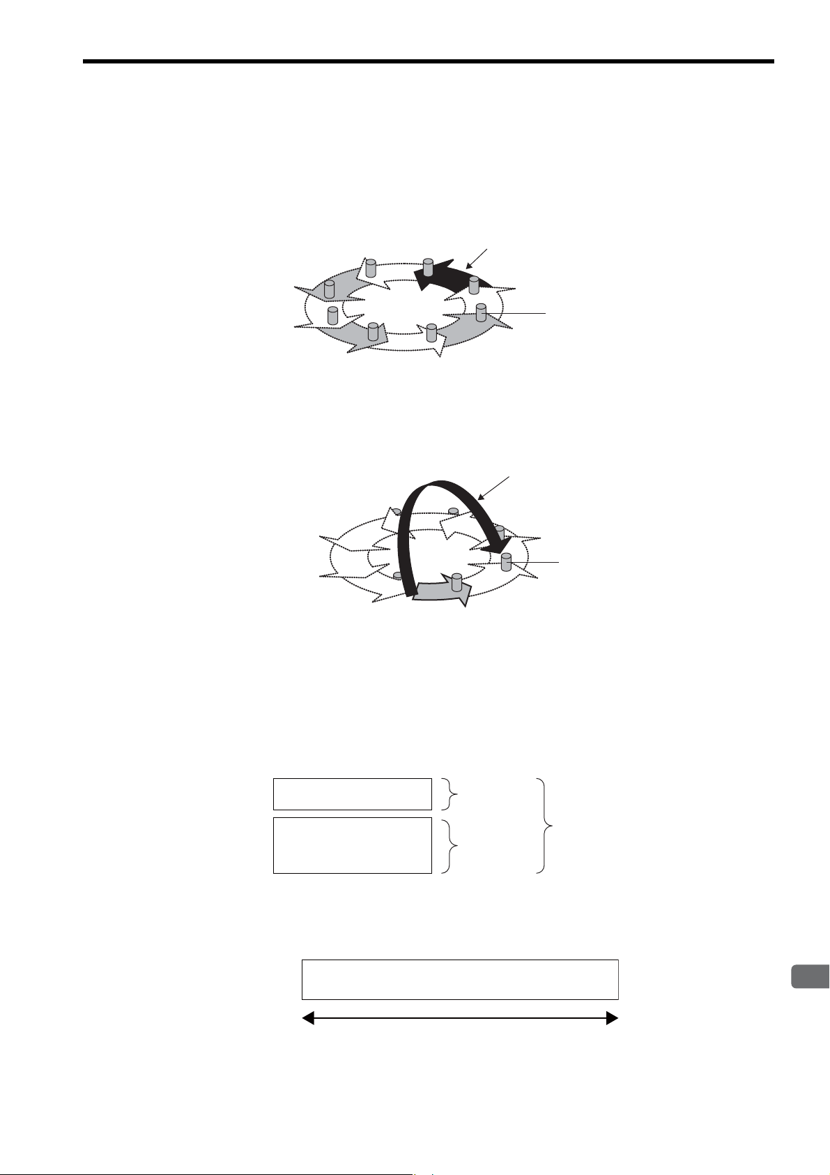
5
Details of FL-net
( 6 ) Data Communication Types
Node
Message data
Area 1 0.5 kword
8 kword
Common memory area
Area 2
Message frame
1,024 bytes
FL-net data communication supports cyclic transmission and message transmission.
Cyclic Transmission
Cyclic transmission is token-based cyclic data transmission. Each node shares data via the common memory.
Cyclic data or token
Node
Message Transmission
Message transmission is non-cyclic data transmission.
Usually, communication with a specific node is performed when a send request is sent.
5.2 About FL-net
5.2.1 FL-net Overview
For details of data communication, refer to 5.3 FL-net Data Communication on page 5-9.
( 7 ) Amount of Transmission Data
Cyclic Transmission
The network has an area of 8.5 kwords (= 8 kbits [0.5 kword] + 8 kword) in all.
The maximum amount of send data available per node is 8.5 kwords. However, one word corresponds to two bytes.
Message Transmission
The maximum amount of data in one message frame is 1,024 bytes (without header).
5-7
Page 75

5.2 About FL-net
Common memory area 1
FL-net
Node
FL-net Module CPU Module
FL-net management table area
FL-net parameter area
Common memory area 2
I/O register
Message transmission
buffer area
Message transmission
buffer area
Machine Controller
5.2.1 FL-net Overview
( 8 ) Data Area and Memory
The following shows the correspondence of memories in the CPU Module and FL-net Module (262IF-01) of the
Machine Controller.
The common memory area corresponds to the I/O registers (IW register, OW register), and the message transmission
buffer area to the MW register.
5-8
Page 76

5
Details of FL-net
5.3 FL-net Data Communication
The following describes data communication, cyclic transmission, and message transmission supported by FL-net in
detail.
5.3.1 Cyclic Transmission
( 1 ) Overview of Cyclic Transmission
Cyclic transmission is a function for cyclic data exchange between nodes.
• The common memory function for each node is realized.
• When the node holds a token, cyclic data to be sent is all sent.
• Nodes not performing cyclic transmission (nodes performing only message transmission) are allowed to join FLnet.
( 2 ) Token and Token Frame
Basically, only one token is present in a network. When the network contains two or more tokens, the node preferentially selects the token with a smaller destination node number and discards the others.
A frame including a token (token frame) has a token destination node number and a token source node number. When
the node number of a node matches the destination node number of a token in a received token frame, the node changes
to a token holder node.
The order of token rotation is determined by the node number. Each node passes the token in the ascending order of
node numbers registered in the joined node management table. A node having the maximum node number passes the
token to a node having the minimum node number.
5.3 FL-net Data Communication
5.3.1 Cyclic Transmission
( 3 ) Refresh Cycle and Refresh Cycle Allowable Time
Cyclic communication refreshes (updates) the common memory at a constant cycle. This update cycle is called a
“refresh cycle.”
FL-net controls the sending of message communication so that the common memory refresh cycle does not exceed the
refresh cycle allowable time during a single message communication.
Each node monitors the message communication frame that flows through the network from when the node receives a
token addressed to itself until it receives another token addressed to itself. When no message communication frame
flows in this specific cycle, a 120% value of this one cycle time is set as the refresh cycle allowable time.
The refresh cycle allowable time is determined automatically by the number of nodes to join the network through the
above monitoring.
( 4 ) Common Memory and Areas 1 and 2
The common memory can be shared among nodes for cyclic transmission.
A node can assign two data areas (called “area 1” and “area 2”) to the common memory. To define a send area, the
leading address and size of an area must be specified.
Area access is performed in units of words. The size of area 1 is 0.5 kword (8 kbits) and that of area 2 is 8 kwords. Each
node can define a node send area freely within the maximum area size of area 1 or area 2.
For details of common memory assignment, refer to 5.3.1 ( 5 ) Assignment of I/O Register and Common Memory on
page 5-10.
5-9
Page 77

5.3 FL-net Data Communication
Set by Transmission Parameters
Tab Page
0000
0004
0010
0012
0511
IW1000
OW1004
IW100A
IW100C
IW1200
OW123C
IW1246
IW1264
IW31FF
6 words
0000
0060
0100
0070
8191
Area 1
Area 2
10 words
㧦Local node (OW register)
㧦Other node (IW register)
FL-net common memory
(Set by Link Assignment
Tab Page)
Node number 1 (input)
Node number 1 (input)
Node number 2 (output)
Node number 2 (output)
Node number 4 (input)
Node number 1 (input)
Node number 2 (output)
Node number 4 (input)
Node number 1 (input)
Node number 2 (output)
Node number 4 (input)
Node number 4 (input)
Common memory area 1 size
(variable in a range from
0 to 200H)
Common memory area 2 size (variable in a range from 0 to 2200H)
(I/O ending register number − common memory area 1 size)
CPU Module I/O register
5.3.1 Cyclic Transmission
( 5 ) Assignment of I/O Register and Common Memory
The FL-net common memory function reads data from or writes it in each node area assigned for the CPU module I/O
registers (IW register, OW register). The 262IF-01 Module uses the engineering tool MPE720 for I/O register assignment and defines the following four items.
• Node number
• Leading address and size of I/O registers
• Address and size of FL-net common memory area 1
• Address and size of FL-net common memory area 2
The following figure shows an assignment example of the FL-net common memory and I/O registers.
The local node areas 1 and 2 serve as the output register (OW) dedicated to sending, and other node areas 1 and 2 as the
input register (IW) dedicated to receiving.
5-10
The I/O registers (IW register, OW register) are defined as a continuous area consisting of areas 1 and 2, and are filled
starting with area 1. In link assignment definition, it is allowed to define only area 1 or area 2.
Page 78

5
Details of FL-net
5.3 FL-net Data Communication
5.3.1 Cyclic Transmission
( 6 ) Common Memory Broadcast
In FL-net cyclic transmission, a token holding node broadcasts data in the area assigned for the node (simultaneous
send communication).
The common memory provides a function for allowing each node to broadcast data in a specific period so that the same
data can be shared in the entire system. Nodes on FL-net respectively employ non-duplicate send areas for data
exchange. In common memory operations, a send area assigned for a certain node serves as a receive area for the other
node.
Data + token
FL-net
Node 01
(Send)
(Receive)
(Receive)
㧦Area assigned to the node
The common memory can be used only for a receive area.
Node 02 Node 03
(Receive) (Receive) (Receive)
(Send)
(Receive)
(Receive)(Receive)
(Receive)
(Send)
(Receive)
Node n
(Receive)
(Receive)
(Send)
Common memory
( 7 ) Assurance of Data Concurrency
When the data size sent by one node exceeds the single frame transmission size, i.e., 1,024 bytes, data is transmitted by
multiple frames. When a segmented data frame is received, common memory is not updated until all frame from one
node is received. The common memory assures data concurrency in units of nodes according to the following procedure.
[ a ] Frame Segmentation when Sending
When a data send request is sent from the upper layer (at the SCAN timing set by link assignment), the node copies its
cyclic data to the buffer, makes preparations for sending, and then sends data sequentially. In this case, however, when
the sending node data size is larger than the size of single frame send data, buffer data is segmented into multiple
frames for sending.
[ b ] Refresh Operation when Receiving
When a receiving node has received all cyclic data from one node, it updates the upper layer and the area to be processed synchronously (it updates the input register value at the SCAN timing set by link assignment).
Even when cyclic data is sent in units of frames, it updates area at the timing when all frame data from one node is
received. When all frame data from the node is not received, all data sent from the node is discarded.
5-11
Page 79

5.3 FL-net Data Communication
5.3.2 Message Transmission
5.3.2 Message Transmission
( 1 ) Overview of Message Transmission
Message transmission is a function for exchanging data between nodes asynchronously.
The following gives a brief description of the basic message transmission function.
• When a node receives a token, a maximum of one frame can be sent prior to cyclic frame send.
• A maximum of 1,024 bytes can be sent at once.
• An algorithm is employed not to exceed the refresh cycle allowable time for cyclic transmission.
• Two transmission modes are supported: One-to-one transmission to a specified node, and one-to-n transmission
to all nodes.
∗ The one-to-n transmission mode is available only for transparent messages, log data clearing, and vendor-spe-
cific messages.
• The one-to-one transmission mode has a delivery confirmation function for checking whether or not the destination has received data correctly.
In message transmission, the data sending side is called “client,” and the data receiving side called “server.”
( 2 ) List of Supported Messages
The following table summarizes the message functions supported by the 262IF-01 Module.
Message Function Server Client
Byte block read
Byte block write
Word block read
Word block write
Network parameter read
Network parameter write
Stop command
Start command
Profile read
Transparent message
Log data read
Log data clear
Message loopback
Vendor-specific message
{ indicates that the function is supported, and × indicates that the function is not supported.
For the relationship between support messages and message functions, refer to 6.3 Combination of FL-net Mes-
sages and Message Functions on page 6-29.
Reads data in units of bytes.
Writes data in units of bytes.
Reads data in units of words.
Writes data in units of words.
Reads network parameter data.
Writes network parameter data.
Stops operation of equipment such as the PC connected to
the upper layer of the FA link protocol.
Starts operation of equipment such as the PC connected to
the upper layer of the FA link protocol.
Reads a device profile.
Provides a transparent service to the upper layer of the FA
link protocol.
Reads log data concerning a specified node.
Clears log data concerning a specified node.
Loops back a received message.
Indicates vendor-specific message service.
××
××
{
{{
{{
× {
× {
× {
{{
{{
{{
{{
{{
××
{
5-12
Page 80

5
Details of FL-net
( 3 ) List of Transaction Codes
Each message has a request or response transaction code in its header for message frame identification.
Transaction Code
Message Function
Transparent message
Word block read
Word block write
Network parameter read
Network parameter write
Stop command
Start command
Profile read
Log data read
Log data clear
Message loopback
Decimal Hexadecimal Decimal Hexadecimal
10000 to 59999 2710 to EA5F – –
65005 FDED 65205 FEB5
65006 FDEE 65206 FEB6
65007 FDEF 65207 FEB7
65008 FDF0 65208 FEB8
65009 FDF1 65209 FEB9
65010 FDF2 65210 FEBA
65011 FDF3 65211 FEBB
65013 FDF5 65213 FEBD
65014 FDF6 65214 FEBE
65015 FDF7 65215 FEBF
Request Response
5.3 FL-net Data Communication
5.3.2 Message Transmission
For notes on actual transaction code input to registers, refer to 6.4 Displaying a Register List and Notes at Register
Input on page 6-30.
( 4 ) Virtual Address Space and Physical Address
A CPU Module register to be accessed by the message transmission command and a register number range are indicated.
A virtual address is represented in 32 bits.
The virtual address will vary depending on CPU.
Register Name Physical Address Virtual Address (hexadecimal notation)
MW register
MW00000 to MW65534 000000000 to 0000FFFE
5-13
Page 81

5.3 FL-net Data Communication
Request message
Response message
Target node number
Virtual address space
16 bits
0x000FFFE
Physical address
0
MP2200
218IF-02 262IF-01
LIO-04SVB-01
CPU-02
LIO-04 LIO-04 LIO-01 LIO-01
5.3.3 Details of Supported Messages
5.3.3 Details of Supported Messages
The following describes each supported message in detail.
( 1 ) Word Block Read
This message function reads data for virtual address space (32-bit address space) of remote node in words (in units of
16 bits for one address) via the network.
The virtual address space has been assigned for a CPU Module MW register (physical address).
( 2 ) Word Block Write
This message function writes data for virtual address space (32-bit address space) of remote node in words (in units of
16 bits for one address) via the network.
The virtual address space has been assigned for a CPU Module MW register (physical address).
Request message
Response message
218IF-02 262IF-01
CPU-02
MP2200
Target node number
LIO-04SVB-01
LIO-04 LIO-04 LIO-01 LIO-01
0x000FFFE
16 bits
0
Virtual address space
Physical address
5-14
Page 82

5
Details of FL-net
( 3 ) Network Parameter Read
Request message
Response message
Target node number
MP2200
218IF-02 262IF-01
LIO-04SVB-01
CPU-02
LIO-04 LIO-04 LIO-01 LIO-01
<Network parameter>
Node number
Vendor name
Manufacturer model
Area 1 leading address
Area 1 size
Area 2 leading address
Area 2 size
Token monitoring time
Minimum allowable frame interval
FA link status
Protocol type
Upper layer status
Refresh cycle allowable time setting value
Refresh cycle measurement value (current value)
Refresh cycle measurement value (maximum value)
Refresh cycle measurement value (minimum value)
This message function reads network parameter information of the remote node via the network.
5.3 FL-net Data Communication
5.3.3 Details of Supported Messages
( 4 ) Device Profile Read
This message function reads system parameter, i.e., device profile information of the remote node via the network.
Request message
Response message
218IF-02 262IF-01
LIO-04SVB-01
CPU-02
MP2200
LIO-04 LIO-04 LIO-01 LIO-01
Target node number
<System parameter>
Common specification version
Identification character
Revision number
Revision date
Device type
Vendor name
Product type name
5-15
Page 83

5.3 FL-net Data Communication
Request message
Response message
Target node number
MP2200
218IF-02 262IF-01
LIO-04SVB-01
CPU-02
LIO-04 LIO-04 LIO-01 LIO-01
Log information
5.3.3 Details of Supported Messages
( 5 ) Log Data Read
This message function reads remote node log information via the network.
The contents of 262IF-01 Module log data are as follows:
Item Offset (byte address) Contents
000 (0000H) Communication socket send count
004 (0004H) Communication socket send error count
Sending/receiving data
Cyclic transmission
Message transmission
ACK
To ke n
Node status
008 (0008H) to 023 (0017H) Not used
024 (0018H) Total reception count
028 (001CH) Total reception error count
032 (0020H) to 095 (005FH) Not used
096 (0060H) Cyclic transmission error count
100 (0064H) to 143 (008FH) Not used
144 (0090H) Message retransmission count
148 (0094H9) Message retransmission error count
152 (0098H) to 167 (00A7H) Not used
168 (00A8H) Message reception error count
172 (00ACH) to 191 (00BFH) Not used
192 (00C0H) ACK error count
196 (00C4H) to 239 (00EFH) Not used
240 (00F0H) Token multiplexing recognition count
244 (00F4H) Token discard count
248 (00F8H) Token resending count
252 (00FCH) to 287 (011FH) Not used
288 (012H) Not used
292 (0124H) Frame waiting status count
296 (0128H) Join count
300 (012CH) Local node leaving count
304 (0130H) Local node leaving count by token skip
308 (0134H) Other node leaving recognition count
312 (0138H) to 511 (01FFH) Not used
5-16
Page 84

5
Details of FL-net
( 6 ) Log Data Clear
Request message
Response message
Target node number
MP2200
218IF-02 262IF-01
LIO-04SVB-01
CPU-02
LIO-04 LIO-04 LIO-01 LIO-01
Log information
Clear
Request message
Response message
Target node number
MP2200
218IF-02 262IF-01
LIO-04SVB-01
CPU-02
LIO-04 LIO-04 LIO-01 LIO-01
This message function clears remote node log information via the network.
5.3 FL-net Data Communication
5.3.3 Details of Supported Messages
( 7 ) Message Loopback
This message function loops back a received message.
Loopback is performed automatically in the 262IF-01 Module.
5-17
Page 85
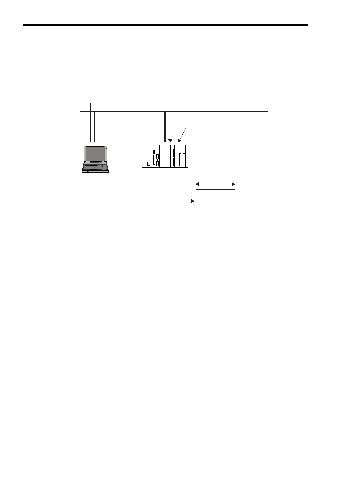
5.3 FL-net Data Communication
5.3.3 Details of Supported Messages
( 8 ) Transparent Message Transmission
This message function writes a message to a receive message area of the remote node via the network.
The 262IF-01 Module does not return an automatic response message even if a transparent message is received.
For this reason, a sequence program must have a response message creation process when it is necessary to
return the response message.
Request message
MP2200
Target node number
218IF-02 262IF-01
LIO-04SVB-01
CPU-02
LIO-04 LIO-04 LIO-01 LIO-01
16 bits
MW register
5-18
Page 86

6
Message Send and Receive Functions
6
Message Send and Receive Functions
This chapter describes message send (MSG-SND) and message receive (MSG-RCV) functions in
detail and sample programs necessary for transmission and reception.
6.1 Message Send Function - - - - - - - - - - - - - - - - - - - - - - - - - - - - - - - - - - - -6-2
6.1.1 Outline Specifications - - - - - - - - - - - - - - - - - - - - - - - - - - - - - - - - - - - - - - - - - - - - - - 6-2
6.1.2 MSG-SND Function Setting Example - - - - - - - - - - - - - - - - - - - - - - - - - - - - - - - - - - - 6-3
6.1.3 Inputs and Outputs for the Message Send Function - - - - - - - - - - - - - - - - - - - - - - - - - 6-3
6.1.4 Parameter List for MSG-SND Function - - - - - - - - - - - - - - - - - - - - - - - - - - - - - - - - - - 6-9
6.1.5 Parameter Details for MSG-SND Function - - - - - - - - - - - - - - - - - - - - - - - - - - - - - - - 6-10
6.1.6 Specifying an FL-net Virtual Address Space Using the MSG-SND Function - - - - - - - 6-15
6.1.7 Relationship among the Data Address, Data Size, and Offset in the MSG-SND
Function - - - - - - - - - - - - - - - - - - - - - - - - - - - - - - - - - - - - - - - - - - - - - - - - - - - - - - 6-16
6.2 Message Receive Function - - - - - - - - - - - - - - - - - - - - - - - - - - - - - - - - - 6-17
6.2.1 Basic Specifications - - - - - - - - - - - - - - - - - - - - - - - - - - - - - - - - - - - - - - - - - - - - - - - 6-17
6.2.2 MSG-RCV Function Setting Example - - - - - - - - - - - - - - - - - - - - - - - - - - - - - - - - - - 6-18
6.2.3 Inputs and Outputs for the Message Receive Function - - - - - - - - - - - - - - - - - - - - - - 6-18
6.2.4 Parameter List for MSG-RCV Function - - - - - - - - - - - - - - - - - - - - - - - - - - - - - - - - - 6-23
6.2.5 Parameter Details for MSG-RCV Function - - - - - - - - - - - - - - - - - - - - - - - - - - - - - - - 6-24
6.2.6 Relationship among the Data Address, Data Size, and Offset in the MSG-RCV
6.3 Combination of FL-net Messages and Message Functions - - - - - - - - - - - 6-29
6.4 Displaying a Register List and Notes at Register Input - - - - - - - - - - - - - - 6-30
6.4.1 Displaying a Register List - - - - - - - - - - - - - - - - - - - - - - - - - - - - - - - - - - - - - - - - - - - 6-30
6.4.2 Notes at Register Input - - - - - - - - - - - - - - - - - - - - - - - - - - - - - - - - - - - - - - - - - - - - 6-32
6.5 Programming Example - - - - - - - - - - - - - - - - - - - - - - - - - - - - - - - - - - - -6-33
6.5.1 Word Block Data Read (Client) - - - - - - - - - - - - - - - - - - - - - - - - - - - - - - - - - - - - - - - 6-33
6.5.2 Word Block Data Write (Client) - - - - - - - - - - - - - - - - - - - - - - - - - - - - - - - - - - - - - - - 6-36
6.5.3 Word Block Data Read/Write (Server) - - - - - - - - - - - - - - - - - - - - - - - - - - - - - - - - - - 6-39
6.5.4 Sending Request (Client)/Response (Server) according to Non-procedure Protocol - 6-42
6.5.5 Sending Request/Receiving Response (Client) according to Non-procedure Protocol 6-45
6.5.6 Receiving Transparent Message Request (Server) - - - - - - - - - - - - - - - - - - - - - - - - - 6-51
Function - - - - - - - - - - - - - - - - - - - - - - - - - - - - - - - - - - - - - - - - - - - - - - - - - - - - - - 6-28
6-1
Page 87

6.1 Message Send Function
6.1.1 Outline Specifications
6.1 Message Send Function
When a request is sent assuming that the 262IF-01 is a client for FL-net message transmission or a response is sent
assuming that it is a server, the message send function “MSG-SND” is used.
When no response comes from remote device, retransmission is performed in the 262IF-01 according to the FL-net
protocol. When a timeout is detected in the 262IF-01, the MSG-SND function is terminated abnormally.
A timeout is detected when no response comes in spite three attempts (each involving a waiting time of 100 ms)
made to receive ACK after sending message.
6.1.1 Outline Specifications
Function Name
Function
Function Definition
I/O Definitions No. Name
Inputs
Outputs
∗ 1. The I/O designations are as follows:
B-VAL: I/O is specified as bit data.
I-REG: I/O is specified as integer data. Specify the number of an integer register.
Constants (immediate data) can also be specified for inputs.
Address input: The address of the specified register (any integer register) is passed to the function.
∗ 2. Non-procedure 1: Data is sent in word units.
MSG-SND
Sends a message to a remote station on the line specified by the Transmission Device Type parameter
(DEV-TYP). The function supports multiple protocols. The Execute command must be held ON until
the Complete or Error output turns ON.
I/O Designation
1 Execute B-VAL Send Message command
2 Abort B-VAL Send Message Abort command
3 Dev-Typ I-REG
4 Pro-Typ I-REG
5 Cir-No I-REG
6 Ch-No I-REG
7 Param Address input
8 Busy B-VAL Processing in progress.
9 Complete B-VAL Processing completed.
10 Error B-VAL Error has occurred.
*1
Transmission Device Type
FL-net = 14
Communication Protocol
MEMOBUS = 1, Non-procedure 1
Circuit Number
FL-net = 1 to 8
Transmission Buffer Channel Number
FL-net = 1 to 10
Parameter List Leading Address
(MA, DA)
Description
*2
= 2
6-2
Page 88

6
Message Send and Receive Functions
6.1.2 MSG-SND Function Setting Example
Transmission device = FL-net
Protocol type = MEMOBUS
Circuit number = 1
Transmission buffer channel number = 1
Parameter list leading address = DA00000
(DW00000 to DW00016 are used.)
This example shows the settings for using the FL-net as the transmission device.
To use the Extended MEMOBUS protocol, the protocol type is set to MEMOBUS.
The circuit number is set to the circuit number assigned to the 262IF-01 transmission device.
Transmission buffer channel numbers in the same line must all be unique.
For details on the settings, refer to 6.1.3 Inputs and Outputs for the Message Send Function on page 6-3.
6.1.3 Inputs and Outputs for the Message Send Function
6.1 Message Send Function
6.1.2 MSG-SND Function Setting Example
( 1 ) Inputs
The following table gives the registers that can be used for the inputs.
Inputs I/O Designation Applicable Registers
Execute
Abort
Dev-Typ
Pro-Typ
Cir-No
Ch-No
Param
The following sections describe the inputs in more detail.
[ a ] Execute (Send Message Execute Command)
Specify the bit that will be used to control execution of the Message Send function.
Message send processing is started when the Execute command turns ON. To execute processing, this bit must be
turned ON and OFF, e.g., from the ladder program.
The Execute command must be held at ON until the Complete or Error output turns ON. The message is sent when
the Execute command turns ON. To send another message, always turn OFF the Execute command for at least
one scan.
[ b ] Abort (Send Message Abort Command)
B-VAL Any bit registers (including those with subscripts) except for # and C registers
I-REG Any integer registers (including those with subscripts) and constants
Address input Any register addresses (including those with subscripts) except for # and C registers
Specify the bit that will be used to abort the Message Send function.
Sending the message will be aborted when the Abort command turns ON. The Abort command takes priority over the
Execute command.
To abort processing, this bit must be turned ON and OFF, e.g., from the ladder program.
[ c ] Dev-Typ (Transmission Device Type)
The Dev-Typ input specifies the transmission device type. The transmission device type of FL-net is 14.
6-3
Page 89

6.1 Message Send Function
6.1.3 Inputs and Outputs for the Message Send Function
[ d ] Pro-Typ (Communication Protocol)
The Pro-Typ input specifies the communication protocol as shown in the following table.
Select 1 (MEMOBUS) or 2 (Non-procedure protocol 1) according to the type of an FL-net message.
Type Code Communication Protocol Remarks
1MEMOBUS
2
3
The following table summarizes the correspondence between the FL-net message and Pro-Typ.
Message Type Function
Word block read
Word block write
Network parameter read
Network parameter write
Stop command
Start command
Profile read
Transparent message
Log data read
Log data clear
Message loopback
Non-procedure 1
(in units of words)
Non-procedure 2
(in units of bytes)
Reads data in units of words.
Writes data in units of words.
Reads network parameter data.
Writes network parameter data.
Stops operation of equipment such as the PC connected
to the upper layer of the FA link protocol.
Starts operation of equipment such as the PC connected
to the upper layer of the FA link protocol.
Reads a device profile.
Provides a transparent service to the upper layer of the
FA link protocol.
Reads log data concerning a specified node.
Clears log data concerning a specified node.
Loops back a received message.
Select for word block read or word block write of FL-net messages.
Select for other than the above message.
Data will be sent in word units using the non-procedure protocol. No
response is received from the remote station.
Not used in FL-net.
Communication Protocol
Server
(Send
Response)
*1
–
*1
–
*2
–
Client
(Send Request)
MEMOBUS
MEMOBUS
Non-procedure 1
Not supported Non-procedure 1
Not supported Non-procedure 1
Not supported Non-procedure 1
*2
–
Non-procedure 1
Non-procedure 1 Non-procedure 1
*2
–
*2
–
*2
–
Non-procedure 1
Non-procedure 1
Non-procedure 1
∗ 1. A response is returned by application receive processing (MSG-RCV function).The MSG-SND function is not
required.
∗ 2. Because the response is sent in the 262IF-01, no send processing by applications (MSG-SND function) is
required.
For the relationship between the FL-net message and message function, refer to 6.3 Combination of FL-net Mes-
sages and Message Functions on page 6-29.
6-4
Page 90

6
Message Send and Receive Functions
6.1 Message Send Function
Circuit number
6.1.3 Inputs and Outputs for the Message Send Function
[ e ] Cir-No (Circuit Number)
The Cir-No input specifies the circuit number of the transmission device.
Set the circuit number to the value displayed in the MPE720 Module Configuration Window.
The valid circuit number range of FL-net is 1 to 8.
[ f ] Ch-No (Channel Number)
The Ch-No input specifies the channel number of the transmission buffer.
Any channel number can be specified as long as it is within the valid range. If more than one function is being executed at the same time, do not specify the same channel number more than once for the same modem number. (The
same channel number can be used as long as the functions are not executed at the same time.)
The valid channel number range of FL-net is 1 to 10.
<Example>
In FL-net (262IF-01), there are 10 channels of transmission buffers from 1 to 10 for sending and receiving combined,
so up to 10 messages can be sent and received at the same time.
One MSG-SND (or MSG-RCV) function must be programmed for each circuit being used at the same time.
6-5
Page 91

6.1 Message Send Function
FL-net node
㩷㩷
㩷㩷 㩷㩷
262IF-01
Node 1
1
2
4
5
6
7
8
9
10
㩷
3
FL-net㩷
FL-net
FL-net
Node 2
FL-net
port
FL-net
port
FL-net
Node 3
FL-net node FL-net node
MP2000 Series
Machine Controller
Remote device #1
Remote device #1
Remote device #2
Remote device #2
Network Configuration Diagram
Transmission
buffer channel
MP2000 Series
Machine Controller
MSG-SND
function
MSG-RCV
function
MSG-RCV
function
MSG-SND
function
FL-net
port
The MSG-SND and MSG-RCV functions use the
262IF-01 transmission buffer channels to perform
message communication. There can be no more
MSG-SND/MSG-RCV functions started simultaneously
than the number of transmission buffer channels. In other
words, there can be only one MSG-SND/MSG-RCV
functions started simultaneously for one transmission
buffer channel.
6.1.3 Inputs and Outputs for the Message Send Function
Conceptual Diagram of Transmission Buffer Channels
The following shows a conceptual diagram of the transmission buffer channels.
6-6
Page 92

6
Message Send and Receive Functions
6.1 Message Send Function
6.1.3 Inputs and Outputs for the Message Send Function
[ g ] Param (Parameter List Leading Address)
The PARAM input specifies the leading address of the parameter list. A parameter list will be automatically created
from the 17 words starting with the specified address. Use the parameter list to input the function code and other
related parameters. The processing results and status are also output to the parameter list.
Refer to 6.1.4 Parameter List for MSG-SND Function on page 6-9 for information on the parameter list.
Example: The following parameter list will be created when the Parameter List Leading Address is set to
DA000000.
Parameter
Register
DW000000 PA RA M0 0
DW000001 PA RA M0 1
DW000002 PA RA M0 2
DW000003 PA RA M0 3
DW000004 PA RA M0 4
DW000005 PA RA M0 5
DW000006 PA RA M0 6
DW000007 PA RA M0 7
DW000008 PA RA M0 8
DW000009 PA RA M0 9
DW000010 PA RA M1 0
DW000011 PA RAM 11
DW000012 PA RA M1 2
DW000013 PA RA M1 3
DW000014 PA RA M1 4
DW000015 PA RA M1 5
DW000016 PA RA M1 6
F x x x x x x 0
( 2 ) Outputs
The following table gives the registers that can be used for the outputs.
Inputs I/O Designation Applicable Registers
Busy
Complete
Error
The following sections describe the outputs in more detail.
[ a ] Busy (Processing in Progress)
Specify the bit that will report when sending the message is being processed.
The Busy output will be ON while message send processing or abort processing is in progress.
Keep the Execute command or Abort command ON while the Busy output is ON.
[ b ] Complete (Processing Completed)
Specify the bit that will report when processing to send the message has been completed.
The Complete output will be ON for only one scan after message send processing or abort processing has been completed normally.
[ c ] ERROR (Error Occurred)
Specify the bit that will report when an error has occurred while sending the message.
The Error output will turn ON for only one scan when an error occurs.
B-VAL Any bit registers (including those with subscripts) except for # and C registers
6-7
Page 93

6.1 Message Send Function
IN: Execute (Send Message Execute Command)
IN: Abort (Send Message Abort Command)
OUT: Busy (Processing in Progress)
Output: Complete
OUT: Error (Error Occurred)
Time
1 scan
To send another message,
always turn OFF the Execute
command for at least one scan
after processing has been
completed for the first message.
IN: Execute (Send Message Execute Command)
IN: Abort (Send Message Abort Command)
OUT: Busy (Processing in Progress)
Output: Complete
OUT: Error (Error Occurred)
Time
1 scan
To send another message, always turn
OFF the Execute command for at least
one scan after processing has been
completed for the first message.
IN: Execute (Send Message Execute Command)
IN: Abort (Send Message Abort Command)
OUT: Busy (Processing in Progress)
Output: Complete
OUT: Error (Error Occurred)
Time
1 scan
To send another message, always
turn OFF the Execute command for at
least one scan after processing has
been completed for the first message.
6.1.3 Inputs and Outputs for the Message Send Function
( 3 ) I/O Timing Chart
The following timing charts show the bit inputs and outputs used with the MSG-SND function.
<Normal Processing>
<Abort Processing>
<Error Processing>
6-8
Page 94

6
Message Send and Receive Functions
6.1.4 Parameter List for MSG-SND Function
The Param input to the MSG-SND function is a parameter list structure consisting of 17 words. The value of the Param
input is the leading address (MA or DA) of the parameter list.
Use the parameter list to input the connection number, function code, and other related parameters. The processing
results and status are also output to the parameter list.
The parameter lists for the MEMOBUS and non-procedure communication protocols in FL-net are given below.
6.1 Message Send Function
6.1.4 Parameter List for MSG-SND Function
PARAM No. IN/OUT Contents
00 OUT Processing result The processing results are output here.
01 OUT Status The status of the current MSG-SND function is output here.
02 IN Remote node number
03 IN Option Not used.
04 IN Function code
05 IN Data address
06 IN Data size
07 IN
08 IN Coil offset Not used.
09 IN Input relay offset Not used.
10 IN Input register offset Not used.
11 IN Holding register offset Sets the offset word address of the holding registers.
12 SYS Reserved by the system (1).
13 to 16 SYS Reserved by the system (2).
IN: Input, OUT: Output, SYS: Used by the system.
Refer to 6.1.5 Parameter Details for MSG-SND Function on page 6-10 for details on the parameters.
∗ Set the lower-place four bits of upper words of the remote station address when the remote station is another manu-
facturer’s product, and set the remote station CPU number when the remote station is Yaskawa CP series.
Remote CPU number
(address upper word)
Pro-Typ=1 (MEMOBUS) Pro-Typ=2 (Non-procedure)
Specifies the destination node number (1 to 254).
When the remote station number is set to 255, data is
sent to all nodes on the FL-net. However, this is valid
only for transparent message and log data clear.
09H: Word block read
0BH: Word block write
Others: Not used.
Specifies the FL-net virtual
address in the range of 0 to
65535.
Specifies the data size in the
range of 1 to 512 words.
Specifies the FL-net virtual address.
When the remote station is 262IF-01: 0
When the remote station is other than 262IF-01: 0 to 15
Description
Setting not required.
Specifies the transaction code
as data leading address.
Specifies the data size in the
range of 1 to 513 words.
*
6-9
Page 95

6.1 Message Send Function
6.1.5 Parameter Details for MSG-SND Function
6.1.5 Parameter Details for MSG-SND Function
This section describes the parameter list in detail for MSG-SND function.
( 1 ) PARAM00: Processing Result
The processing result is output to the upper-place byte of PARAM00. The lower-place byte is for system analysis.
Value of Processing Result Meaning
00H Processing in progress (busy)
10H Processing completed (Complete)
8yH Error occurred (Error)
If an error occurs, troubleshoot the problem according to the value of the processing result as listed below.
Error Error Contents Description
80H – Reserved by the system.
81H Function code error
82H Address setting error
83H Data size error
84H Circuit number setting error
85H Channel number setting error
86H Remote node number error
87H ––
88H Transmission device error
89H Device selection error
8072H to
FF72H
Remote node error
An undefined function code was sent or received.
Check PARAM04 (function code).
One of the following settings in not within the valid range. Check the settings.
PARAM05 (data address)
PARAM11 (holding register offset)
The size of the sent or received data is not within the allowable range.
Check PARAM06 (data size).
The circuit number is not within the allowable range.
Check the circuit number in the MSG-SND function.
The transmission buffer channel number is not within the allowable range.
Check the transmission buffer channel number in the MSG-SND function.
The remote node number is not within the allowable range.
Check PARAM02 (remote node number).
An error response was returned from the transmission device.
Check the connection to the equipment. Also, be sure that the remote device
can communicate.
An unavailable device was set. Check the transmission device type in the
MSG-SND function.
An error response was returned from the remote node. Refer to error code and
remove the cause.
• Refer to the following Datails of Remote Node Error on page 6-10.
6-10
Datails of Remote Node Error
The following shows the contents of the message function PARAM00 (processing results) at error response reception
from a remote node.
Processing result (PARAM00): 72H ( indicates the error code.)
While the FA link specification states that an error code is one byte (eight bits), the MP specification states the high-
est bit of a processing result is fixed to “1”, so the parameters that can be identified error codes are the remaining
seven bits.
(“1 * * * * * * ”... * indicates a bit available as an error code.)
Accordingly, 00H to 7FH for seven bits can be represented as error codes.
<When the remote node is an MP Machine Controller>
Processing Result Error Contents
8172H
8272H
8372H
FF72H
Error code=1 (function error)
Error code=2 (reference number error)
Error code=3 (data count error)
Remote device does not respond.
Page 96

6
Message Send and Receive Functions
<When the remote node is another manufacturer's controller>
Bit F,
1 REQUEST
F78 65432109ABCDE
Bits C to E,
2 RESULT
Bits 8 to B,
3 COMMAND
Bits 0 to 7,
4 PARAMETER
1
2
Processing Result Error contents
8072H
8172H to FE72H
FF72H
Error with error code=80H occurred (Error contents vary depending on manufacturers.)
Error with error code=01H to 7EH occurred (Error contents vary depending on manufacturers.)
Or, error with error code=81H to FFH occurred (Error contents vary depending on manufacturers.)
Error with error code=00H occurred (Error contents vary depending on manufacturers.)
Or, error with error code=7FH occurred (Error contents vary depending on manufacturers.)
Or, error with error code=FFH occurred (Error contents vary depending on manufacturers.)
Or, remote device does not respond.
( 2 ) PARAM01: Status
The status of the transmission device is output to PARAM01.
Bit allocations are shown in the following figure and described after the figure.
6.1 Message Send Function
6.1.5 Parameter Details for MSG-SND Function
REQUEST
The status of the processing request for the MSG-SND function is output to this bit.
Bit Status Meaning
1 Processing is being requested.
0 Processing request has been accepted.
RESULT
The result of executing MSG-SND function is output to these bits.
Code Abbreviation Meaning
0
1
2
3
4
5
6
7
CONN_NG
SEND_OK
REC_OK
Abort_OK
FMT_NG
SEQ_NG or INIT_NG
RESET_NG or O_RING_NG
REC_NG
Sending or connection has ended abnormally for FL-net communication.
Sending has been completed normally.
Receiving has been completed normally.
Abort completed.
Parameter format error
Command sequence error.
Not connected to the transmission system.
Reset status or out of ring.
The token could not be received because the token monitoring time
was exceeded.
Data receive error (Error detected by a lower-layer program.)
6-11
Page 97

6.1 Message Send Function
3
4
6.1.5 Parameter Details for MSG-SND Function
COMMAND
The processing command for the MSG-SND function is output to these bits. The processing that is executed depends
on the setting of the COMMAND bits.
Code (Hex) Abbreviation Meaning
1
2
3
8
9
C
U_SEND
U_REC
ABORT
M_SEND
M_REC
MR_SEND
PARA METE R
The following error code is output if RESULT is set to 4 (FMT_NG: parameter format error). In other cases, the remote
node number is output.
RESULT Code Meaning
RESULT = 4 (FMT_NG: parameter format error)
Other values of RESULT Remote node number
Send General-purpose Message with Non-procedure Protocol
Receive General-purpose Message with Non-procedure Protocol
Abort
Send MEMOBUS command; executing the command is completed upon receiving a response.
Receive MEMOBUS command; executing the command is followed by sending a response.
Send MEMOBUS response
00 No errors
01 Remote node number out of range
02 MEMOBUS response receive monitor time error
03 Retry count setting error
04 Cyclic area setting error
05 CPU No. error
06 Data address error
07 Data size error
08 Function code error
( 3 ) PARAM02: Remote Node Number
Specifies the destination node number (1 to 254).
The details of the remote node information including node number can be checked on the Network Configuration
Window. Refer to 4.2.6 Network Configuration Window on page 4-13 for the Network Configuration Window.
( 4 ) PARAM04: Function Code (Only When Extended MEMOBUS Is Used)
PARAM04 sets the function code to be sent (setting is not required for non-procedure protocol).
The function registered to the function code is used by specifying the function code here. Functions include reading
coil and input relay status and writing holding registers.
The function codes used for the MEMOBUS or Extended MEMOBUS protocol are listed in the following table.
<Function Codes>
Function
Code
00H to 07H
09H
0AH
0BH
0CH to 10H
W: Word data
{: Can be set,
Applicable
Data Type
–
W
–
W
–
Not used.
Word block read
Not used.
Word block write
Not used.
×: Cannot be set.
Function
Protocol Type
Extended
MEMOBUS
––
{
––
{
––
MEMOBUS
×
×
6-12
Page 98

6
Message Send and Receive Functions
6.1 Message Send Function
6.1.5 Parameter Details for MSG-SND Function
( 5 ) PARAM05: Data Address
For the relationship among data address (PARAM05), data size (PARAM06), and holding register offset
(PARAM011), refer to 6.1.7 Relationship among the Data Address, Data Size, and Offset in the MSG-SND Function
on page 6-16.
[ a ] When Pro-Typ=1 (MEMOBUS)
PARAM05 sets an FL-net virtual address in the range of 0 to 65535 as the leading address of the data.
The address is input as a decimal or hexadecimal value.
Example: To set a leading address of MW01000, set 1000 (decimal) or 3E8H (hexadecimal).
In FL-net, the offset address of the FL-net virtual address space (M_ADD) is specified by the data address (PARAM05)
and the remote CPU number (PARAM07). For details, refer to 6.1.6 Specifying an FL-net Virtual Address Space Using
the MSG-SND Function on page 6-15.
[ b ] When Pro-Typ=2 (non-procedure protocol)
Specify the transaction code in the leading register of the data address in decimal or hexadecimal value.
The following table lists transaction codes.
Transaction Code
Message Type
Transparent message
Word block read
Word block write
Network parameter read
Network parameter write
Stop command
Start command
Profile read
Log data read
Log data clear
Message loopback
Decimal Hexadecimal Decimal Hexadecimal
10000 to 59999* 2710 to EA5F* – –
65005 FDED 65205 FEB5
65006 FDEE 65206 FEB6
65007 FDEF 65207 FEB7
65008 FDF0 65208 FEB8
65009 FDF1 65209 FEB9
65010 FDF2 65210 FEBA
65011 FDF3 65211 FEBB
65013 FDF5 65213 FEBD
65014 FDF6 65214 FEBE
65015 FDF7 65215 FEBF
Request Response
∗ Any value is valid as long as it is within the range.
Example: To set a leading address of MW10000, set 10000 (decimal) or 2710 (hexadecimal).
For notes at actual register input, refer to 6.4 Displaying a Register List and Notes at Register Input on page 6-30.
6-13
Page 99

6.1 Message Send Function
6.1.5 Parameter Details for MSG-SND Function
( 6 ) PARAM06: Data Size
PARAM06 specifies the data size to be read or written in the range of 1 to 513 words.
Do not allow the final address of the data, which is determined by the offset (PARAM11), data address (PARAM05),
and data size, to exceed the valid range of addresses.
Because a one-word transaction code is set at the beginning of the data when Pro-Typ=2 (non-procedure protocol) is
used, the size must be set including the transaction code size.
The following table shows a setting data size (including a one-word transaction code) for each message.
Message Type Pro-Typ Data Size (word) Remarks
Word block read
Word block write
Network parameter read
Network parameter write
Stop command
Start command
Profile read
Transparent message
Log data read
Log data clear
Message loopback
MEMOBUS 1 to 512 (arbitrary)
MEMOBUS 1 to 512 (arbitrary)
Non-procedure protocol 1 Only transaction data is sent.
Non-procedure protocol 11
Non-procedure protocol 1 Only transaction data is sent.
Non-procedure protocol 1 Only transaction data is sent.
Non-procedure protocol 1 Only transaction data is sent.
Non-procedure protocol 2 to 513 (arbitrary)
Non-procedure protocol 1 Only transaction data is sent.
Non-procedure protocol 1 Only transaction data is sent.
Non-procedure protocol 2 to 513 (arbitrary)
For the relationship among data address (PARAM05), data size (PARAM06), and holding register offset
(PARAM011), refer to 6.1.7 Relationship among the Data Address, Data Size, and Offset in the MSG-SND Function
on page 6-16.
( 7 ) PARAM07: Remote CPU Number
PARAM07 sets the remote CPU number.
• Set the remote CPU number to 0 if the remote device is a 262IF-01.
• When a remote device is another manufacturer's product, set the low-place four bits of upper word of a remote
device address.
• When a remote device is YASKAWA CP series, set a remote CPU number.
In FL-net, the offset address of the FL-net virtual address space (M_ADD) is specified by the data address
(PARAM05) and the remote CPU number (PARAM07). For details, refer to 6.1.6 Specifying an FL-net Virtual
Address Space Using the MSG-SND Function on page 6-15.
( 8 ) PARAM11: Holding Register Offset
PARAM11 sets the offsets for the data read or write location at the device sending the message.
The position of the data is shifted backward by the number of words set for the offset at the device sending the message.
For the relationship among data address (PARAM05), data size (PARAM05), and holding register offset
(PARAM011), refer to 6.1.7 Relationship among the Data Address, Data Size, and Offset in the MSG-SND Function
on page 6-16.
Negative offsets cannot be set.
6-14
( 9 ) PARAM12: Reserved by the system (1).
PARAM12 is used by the system. (The current transmission buffer channel number is held here.)
Make sure that the user program sets this parameter to 0 in the first scan after the power is turned ON. Thereafter,
do not change the value set for this parameter because the system will use it.
( 10 ) PARAM13 to PARAM16: Reserved by the System (2)
These parameters are used by the system. Do not change the values set for these parameters.
Page 100

6
Message Send and Receive Functions
6.1 Message Send Function
6.1.6 Specifying an FL-net Virtual Address Space Using the MSG-SND Function
6.1.6 Specifying an FL-net Virtual Address Space Using the MSG-SND Function
An offset address (M_ADD) on the FL-net virtual address space in the FL-net message header information is specified
by a data address (PARAM05) and a remote CPU number (address upper word: PAEAM07). In this case, however, the
262IF-02 is allowed to specify 32-bit addresses in a range of virtual address space from 0 to FFFFFH.
PARAM
05
07
Data address
Remote CPU number
M_ADD
㧔0000H to FFFFH㧕
㧔0 to FH㧕
When remote device is other than 262IF-01,
this CPU number can be specified in a range
from 0 to F as the address upper word.
0
3116 1512110
When the FL-net Equipment Other Than the 262IF-01 Accesses the 262IF-01:
When the FL-net equipment other than the 262IF-01 accesses the 262IF-01, an offset address (M_ADD) for virtual
address space must be specified as shown in the following figure.
3116 1512110
M_ADD
0
Data address
(0 to 65534: MW00000 to MW65534)
CPU number (0)
6-15
 Loading...