

Page 1
J50M
INSTRUCTIONS
CNC SYSTEM FOR MACHINING CENTERS
Before initial operation, read these instructions thoroughly, and retain for future reference
Page 2
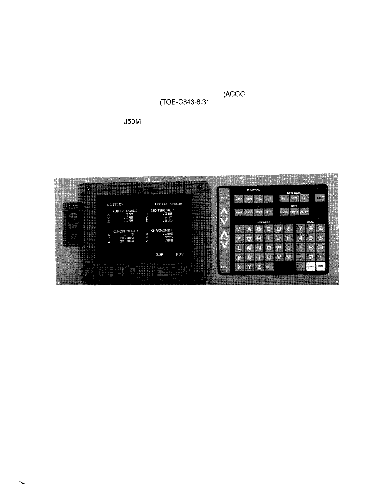
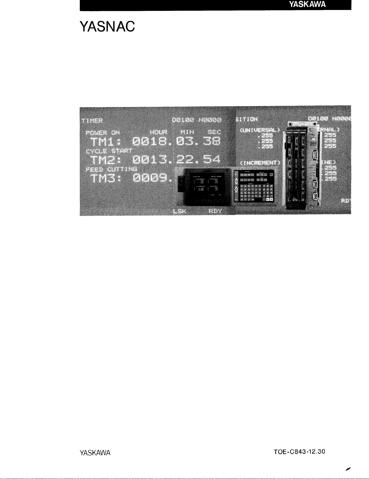
This manual is primarily intended with 9“ CRT character display to
give operators instructions for YASNAC J50M programming, operation and maintenance.
For operation of 14“ CRT character display
the instruction manual
) separately provided.
optional), refer to
This manual applies to the basic and optional features of
YASNAC
The optional features are marked with a dagger.
For the specifications of your YASNAC J50M, refer to the machine
tool builder’s manual.
YASNAC J50M Operator’s Panel
with 9“ CRT Character Display
94-C84-123
2
Page 3
CONTENTS
Page
2.
‘PROGRAM MIN G . . . . . . . . . . . . . . . . . .
2.1
INPUT FORMAT """" """" """"
2.2
PROGRAM NUMBER AND SEQUENCE NUMBER
2.3
COORDINATE WORD
2.4
TRAVERSE AND FEED FUNCTIONS
2.5
SPINDLE-SPEED FUNCTION (S-FUNCTION)
2.6
TOOL FUNCTION (T-FUNCTION).
2.7
TOOL COMPENSATION ““”” ””-””””””””””””””””””””””””””””” ““”” ””””o ””””’””””””””””””””””””””””
2.8
MISCELLANEOUS FUNCTIONS (M-FUNCTION) ‘“ ””’”””””””””-”””””””””””””””””””’””
2.9
PREPARATORY FUNCTION (G-FUNCTION)
2.10
2.11 uSERMACRO (G65, G66, G67) ““.
2.12 SOLID TAP FUNCTION
2.13 AUTOMATIC CORNER OVERRIDE . . . .
2.14 HIGH-SPEED CONTOURING FUNCTION*
3.
PART PROGRAM TAPE CODING
. . . . . . . . . . . . . . . . . . . . . . . . . . . . . . . . . . . . . . . . . . . . . . . . . . . . .
. . . . .
. . . . . . . . . . . . . . . . . . . . . . . . . . . . . . . . . . . . . . . . . . . . . . . . . . . . . . . . . . .
3.1 T~ECODE
3.2 PROGRAMMING
3.3 PART PROGRAM TAPE PUNCHING
3.4 PART PROGRAM TAPE HANDLING
4. NC
OPERATOR’S PANEL WITH 9“ CRT CHARACTER DISPLAY
4.1
PUSHBUTTONS, LAMPS AND KEYS
4.2
POWER
4.3
DISPLAY AND WRITING OPERATION
4.4
TAPE INPUT/OUTPUT OPERATIONS
4.5
LOADING PART PROGRAMS INTO MEMORY
4.6
EDIT OF PART PROGRAM
4.7
SUPPLEMENT TO DATA
4.8
TAPE VERIFYING ““”” ”””””””””””””””””””””””””””””””””
5. MACHINE CONTROL STATION
5.1
SWITCHING UNITS ON THE CONTROL STATION . . . . . . . . . . . . . . . . . . . . . . . . . . . . . . . . . . . . . . . . . . . . . . . . . . . . . . . . ...164
5.2 OPERATION PROCEDURE
OPERATION
. . . . . . . . . . . . . . . . . . . . . . . . . . . . . . . . . . . . . . . . . . . . . . . . . . . . . . . . . . . . . . . . . .
. . . . . . . . . . . . . . . . . . . . . . . . . . . . . . . . . . . . . . . . . . . . . . . . . . . . . . . . . . . . . . . . . . . . . . . . . . . . .
. . . . . . . . . . . . . . . . . . . . . . . . . . . . . . . . . . . . . . . . . . . . . . . . . . . . . . . . . . . . . . . . . . . . . . . . . .
6.1
INSPECTION BEFORE TURNING ON POWER
6.2
TURNING ON POWER
MANUAL OPERATION
6.3
PREPARATION FOR STORED LEADSCREW ERROR COMPENSATION
6.4
AND STORED STROKE LIMIT
PREPARATION FOR AUTOMATIC OPERATION
6.5
6.6
OPERATION IN TAPE AND MEMORY MODE . .
6.7
AUTOMATIC OPERATION IN MDI MODE
6.8
MDI OPERATION INTERRUPTING AUTOMATIC OPERATION
6.9
6.10
6.11 TURNING OFF POWER
7.1 ROUTINE INSPECTION SCHEDULE . .
7.2 BATTERY REPLACEMENT””””””””
7.3
7.4 THERMAL OVERLOAD RELAY OF SERVO UNIT
7.5 MOLDED-CASE CIRCUIT
7.6 TROUBLE CAUSES AND REMEDIES
OPERATION INTERRUPTING AUToMATIc opERATIoN . . . . . . . . . . . . . . . . . . . . . .
PREPARATION FOR TURNING OFF
. . . . . . . . . . . . . . . . . . . . . . . . . . . . . . . . . . . . . . . . . . . . . . . . . . . . . . . . . . . . . . . . . . . . . . . . . . . . . . . . . . . .
. . . . . . . . . . . . . . . . . . . . . . . . . . . . . . . . . . . . . . . . . . . . . . . . . . . . . . . . . . . . . . . . . . . . . . . . . . . . . . . . . . .
. . . . . . . . . . . . . . . . . . . . . . . . . . . . . . . . . . . . . . . . . . . . . . . . . . . . . . . . . . . . . . . . . . . . . . . . . . . . . . . . . .
APPENDIX-1 LIST OF SETTING NUMBERS
APPENDIX-2
STORED LEADSCREW
APPENDIX-4 LISTOFSTANDARD
OF
APPENDIX-5 LIST
ALARM
INPUT
/•
CODES
APPENDIX-6 LIST OF ADDRESS CHARACTERS
. . . . . . . . . . . . . . . . . . . . . . . . . . . . . . . . . . . . . . . . . . . . . . . . . . . . . . . . . . . . . . . . . . . .
““” -”””””””””””””””””””””””
"""" """"
. . . . . . . . . . . . . . . . . . . . . . . . . . . . . . . . . . . . . . . . . . . . . . . . . . . . . . . . . . . . . . . . . .
”””””””””””””””””””””””””””””””””
. . . . . . . . . . . . . . . . . . . . . . . . . . . . . . . . . . . . . . . . . . . . . . . . . . . . . . . . . . . . . . .
"""" """" """"
”””””””””””””””””””””””””””””””” ““”” ””””””””””””””’”””””””’”””””””””
. . . . . . . . . . . . . . . . . . . . . . . . . . . . . . . . . . . . . . . . . . . . . . . . . . . . . . . . . . . . . ...11
. . . . . . . . . . . . . . . . . . . . . . . . . . . . . . . . . . . . . . . . . . . . . . . . . . . . . . . . . . . . . . . .
. . . . . . . . . . . . . . . . . . . . . . . . . . . . . . . . . . . .
””””””””””””””””””””””””””””””””
”””””””””””””””””””””””’”””””””
. . . . . . . . . . . . . . . .
“””””””’”’”””’””””””””””””’”””””””
. . . . . . . . . . . . ...119
. . . . . . . . . . . . . . . . . . . . . . . . . . . . . . . . . . . . . . . . . . . . . . . . . . . . . . . . . . . . . . . . . . . . . . . . . . .
”””’”””””””””””””””””””””””””””””
. . . . . . . . . . . . . . . . . . . . . . . . . . . . . . . . . . . . . . . . . . . . . . . . . . . . . . . . ...132
. . . . . . . . . . . . . . . . . . . . . . . . . . . . . . . . . . . . . . . . . . . . . . . . .
”””” ”””” ””””” ”””” ””””” ””””
. . . . . . . . . . . . . . . . . . . . ...133
. . . . . . . . . . . . . . . . . . . . . . . . . . . . . . . . . . . . . . . . . . . . . . .
. . . . . . . . . . . . . . . . . . . . . . . . . . . . . . . . . . . . . . . . . . . . . . . . . . . . . . . . . . . . . . . . . . . .
. . . . . . . . . . . . . . . . . . . . . . . . . . . . . . . . . . . . . . . . . . . . . . . . . . . . . . . . . . . . . . . . . . .
““”” ”””””””””””””””””””””””””””””
INTERFAcEt ““”” ””””””””””””””””””””””””””””””””
”””””””””””””””””””””””””””””””” ““””””””””<””””161
”””””””””””””””””””””””””””””’ ““””””151
””””
. . . . . . . . . . . ...174
. . . . . . . . . . . . . . . . . . . . . . . ...191
”’””””””””””””””””””””””””””””””” ““”” ”””” ”””” ”””” ”””” ””””
. . . . . . . . . . . . . . . . . . . . . . . . . . . . . . . . . . . . . . . . . . . . . . . . . . . . . . . . . . . . . . . . . . . . . . . . . . .
““”” ”””””””””’”””””””””””””””””
. . . . . . . . . . . . . . . . . . . . . . . . . . . . . . . . . . . . . . . . . . . . . . . . . . . . . . . . . . . . . . . . . . ...196
““” ” ” ” ” ” ” ” ” ” ” ” ” ” ” ” ” ” ” ” ” ””””””-”” ““” ””””””””””””””””””””-””””””””
. . . . . . . . . . . . . . . . . . . . . . . . . . . . . . . . . . . . . . . . . ...-..........................199
. . . . . . . . . . . . . . . . . . . . . . . . . .
. . . . . . . . . . . . . . . . . . . . . .
. . . . . . .
. . . . . . . . . . . . . . . . . . . . . . . . . . . . . . . . . . . . . . . . . . . . . . . . . . . ...192
. . . . . . . . . . . . . . . . . . . . . . . . . . . . . . . . . . . . . . . . . . . . . . . . . . . . . . . . . . .
. . . . . . . . . . . . . . . . . . . . . . . . . . . . . . . . . . . . . . . . . . . . . . . . . . . . . . . . . . . . . . ...193
. . . . . . . . . . . . . . . . . . . . . . . . . . . . . . . . . . . . . . . . . . . . . . . . . . . . ...194
””””””””””’”””””””””””””””””””
. . . . . . . . . . . . . . . . . . . . . . . . . . . .
. . . . . . . . . . . . . . . . . . . . . . . . . . . . . . . . . . . . . . . . . . . . . . . .
. . . . . . . . . . . . . . . . . . . . . . . . . . .
""""
. . . . . . . . . . . . . . . . . . . . . . . . . . . . . . . . . .
. . . . . . . . . . . . . . . . . . . . . . . . . . . . . . . . . . . . . ...196
. . . . . . . . . . . . . . . . . . . . . . . . . . .
. . . . . . . . . . . . . . . . . . . . . . . . . . . . . ...198
. . . . . . . . . . . . . . . . . . . . . . . . . . . . . . . . . . . . . ...202
"". """" """"
. . . . . . . . . . . . . . . . . . . . ...193
. . . . . . . . . . . ...193
. . . . . . . . . . . ...199
. . . . . . . . . . . . . . . . . . . ...239
SIGNALS
. . . . . . . . . . . . . . . . . . . . . . . . . . . . . . . . . . . . . . . . . . . . . . . . ...243
. . . . . . . . . . . . . . . . . . . . . . . . . . . . . . .
. . . . . . . . . . . . . . . . . . . . . . . . . . . . . . . . . . . .
. . . . . . . . .
. . . . . . . . . . . . . . . . . . . ...282
. . . . . . . . . . ...254
1
1
5
. . . .
12
19
. . ...125
130
134
134
137
191
191
192
193
194
. . ...196
1
6
9
111
Page 4
INDEX
Subject Chapter
A ABSOLUTE/INCREMENTAL PROGRAMMING (G90,G91)
ADDING PART PROGRAM
ADDRESS AND FUNCTION CHARACTERS
ADDRESS SEARCH ------------- .
ALARM CODE DISPLAY
ALARM CODES AND REMEDIES
ALARM MESSAGE DISPLAY BY
ALARM NUMBER OF USER MACROS .
AUTOMATIC COORDINATE
AUTOMATIC CORNER OVERRIDE
AUTOMATIC OPERATION IN MDI MODE
AXIS INTERLOCK INPUT
B
BATTERY REPLACEMENT -”-----””
BEFORE MAINTENANCE CALL”--””
BUFFER REGISTER
C CABLE CONNECTOR SPECIFICATIONS
CANNED CYCLES
CIRCUIT PROTECTOR TRIP (ALARM NO. 331 TO 334)
CIRCULAR INTERPOLATION (G02, G03)
CIRCULAR PATH MODE ON/OFF ON
CIRCULAR PROJECTION COMPENSATION
CONDITIONS FOR ADDING SOLID TAP FUNCTIONS
CONSIDERATIONS AND REMARKS FOR USER MACROS
CONTROL COMMANDS
CONTROL PANEL
D
DATA KEYS
DECIMAL POINT PROGRAMMING
DELETING PART PROGRAM BLOCK (ERASE KEY)
DESCRIPTION ON PROGRAMMING
DISPLAY AND WRITE OF LOCAL VARIABLES
DISPLAY
DISPLAY IN THE
DISPLAY LOCK/MACHINE LOCK SWITCH
DISPLAY OF REGISTERED PROGRAM
DISPLAYING AND RESETTING CURRENT
DISPLAYING AND WRITING PARAMETERS
DISPLAYING AND WRITING TOOL OFFSET AND WORK OFFSET 4 -- --
DWELL
. . . . . . . . . . . . . . . . . . . . . . . . . . . . . . . . . . . . . . . . . . . . . .
. . . . . . . . . . . . . . . . . . ...-”
TOOL RADIUS COMPENSATION C(M97,
DISPLAY
CHARACTER DISPLAY
. . . . . . . . . . . . . . . . . . . . . . . . . . . . . . . . . . . . . . . . . . . . . . . . . . . . . . . . .
. . . . . . . . . . . . . . . . . . . . . . . . . . . . . . . . . . . . . . . . . . . . . . . . . . . . . . . .
oFFsETl-
. . . . . . . . . . . . . . . . . . . . . . . . . . . . . . . . . . . . . . . . . . . . .
. . . . . . . . . . . . . . . . . . . . . . . . . . . . . . . . . . . . .
G74, G76, G77, G80 TO G89, G98, G99)
. . . . . . . . . . . . . . . . . . . . . . . . . . . . . . . . . . . . . . . . . . . . . . .
. . . . . . . . . . . . . . . . . . . . . . . . . . . . . . . . . . . . . . . . . . . . . . . . . . . .
-- ...-..”” ““””
NUMERICAL SEnINGFUNCTION
"." . .
(SETTING) FUNCTION--”-””-”””””
”oo+”-oooo”
AND LAMP" "".
. . . . . . . . . . . . . . . . . . . . . . . . . . . . . . . .
. . . . . . . . . . . . . . . . . . . . . . . . . . . . . .
. . . . . . . . . . . . . . . . . . . . . . . . . . . . . . . . . . . . . .
COMMAND
. . . . . . . . . . . . . . . . . . . . . . . . . . . . . . . . . . . . .
““”” ”--”
"".
. . . . . . . . . . . . . . . . . . . . . . . . . . . . . . . . . . . . .
. . . . . . . . . . . . . . . . . . . . . . . . . . . . . . . . . . . .
"".
. . .
. . . . . . . . . . . . . . . . . . . . . . . . . . .
POINT
--
. . . . . . . . . . . . . . . . . . . . . . . . . . . . .
””””
””””
"".
"".
””. ”.-+
. . . . . . . . . . . . . . . . .
. . . . . . . . . . . . . . . . . . . . . .
”””’ ” ”” ” ”” ”-’-----” 5
"oo""
4””. ””.
. . . . . . . . . . . .
. . . . . . . . . . . .
. . . . . . . . . . . .
-
. . . . . . . . . . . .
--
. . . . . . . . . . . .
. . . . . . . . . . . .
. . . . . . . . . . . . . . . . . . . .
””.
””””
"".
””””
. . . .
. .
””””
. . . . . . . . . . . . . . . . . . . . . .
”””” ”””” ”””” ”””” ”””” ”””””” S
"".
"".
.""
--””-----
Par.
. . . . . . . .. 2.9.30 .”....... 85
2
. . . . . ...4.6.4
4
. . . . . . . .
2
. . . . . . . . 4.1.4
4
. . . . . ...4.3.11 . . . . . . ...150
4
. . . . . . . . 7.6.2
. . . . . ...2.10.1 . . . . . . . . . 93
2
““””””””2.11.11
””.
2
2
2
5
7
7
7
2
4
2
3
7
2
2
7
4
2
4
2
4
2
..2.9.35
2.4.5
””-” 5.2.2
. . . . . . . . 2.13
”””” 6.8
. .
. . . . . ...7.1.3
. . . . . ...7.2
. . . . . . . .
. . . . . . . . 4.7.4
. . . . . ...2.9.28 .
.02.9.9
. .
. . . . . ...2.14.3.........129
2
2
””””
. . . . . .
‘+”” $.-”
5.2.9
-”””
. . . . . ...4.1.5
. . . . . . . .
. . . . . ...4.6.2
. . . . . .
‘“”-- ””” 4.5.4
”””” 4.3.7
. . . . . . . . 2.9.6
. . . . . . . ...158
. . . . . . . . . .
. . . . . . . ...135
. . . . . . . ...199
-””-0 92
. . . . . . . ...125
. . . . . ...--196
. . . . . . . .
. . . . . . .
. . . . . . . . . .
. . . . . . . ...160
. . . . . . . ...133
3.2.3
. . .
7.4.1
2.8.6
””””
-”. -”-138
. . . . . . ...-196
. . . . . . . . . . .
. . . . . . . . . .
. . . . . . . ...135
. . . . . . . .
. . . . . . . ...157
. . .
.“”+.
4.3.4
4.3.5
. . . . . . . . . . 25
”-176
”172
26
. . .
”120
”112
”-146
”169
Page
3
96
33
5
68
22
6
6
5
iv
Page 5
INDEX (Cent’d)
Subject
E
EDIT OF PART PROGRAM
EDIT KEYS
EDIT LOCK
EXACT STOP
EXERCISES OF USER MACRO
EXTERNAL DECELERATION INPUT SIGNALSI”
. . . . . . . . . . . . . . . . . . . . . . . . . . . . . . .
AUTO-SELECT
F
FEED HOLD PUSHBUTTON AND LAMP ““” ”””””””””””””””””””””””””””””” 5
FEED STOP FUNCTION
FEEDRATE (F-FUNCTION)
FEEDRATE 1/10 --
FEEDRATE OVERRIDE CANCEL SWITCH
FEEDRATE OVERRIDE SWITCH
FORM COMPENSATION FUNCTION
4TH AXIS CONTROL
4TH AXIS NEGLECT INPUT
G
GENERAL PART PROGRAM FORM
H
H- AND D-FUNCTION (H, DCODES)-o
HANDLE AXIS SELECT SWITCH
HANDLE DIAL
HELICAL INTERPOLATION
HIGH-SPEED CONTOURING FUNCTION*
HOLE PATTERN CYCLES
I
IMPORTANT ALARM CODES-”’””
INPUT/OUTPUT SIGNALS
INPUTTING SETTING DATA AND PARAMETER DATA . . . . . . . . . . . . . . . . . . . 4 . . . . . . . .
INPUTTING TOOL OFFSETS FROM TAPE
INSPECTION
INTERNAL TOGGLE SWITCHES
J
JOG
PUSHBUTTONS””””””--””””””
K
L
LABEL SKIP FUNCTION
LEAST INPUT INCREMENT AND LEAST OUTPUT INCREMENT
LINEAR INTERPOLATION
LIST
LIST OF ALARM CODES
LIST OF
IST OF PARAMETER NUMBERS-”--
L
LIST OF SETTING NUMBERS
LIST OF STANDARD INPUT/OUTPUT SIGNALS
LOADING PART PROGRAMS BY MDI
LOADING PART PROGRAM TAPE INTO MEMORY
LOADING PART PROGRAMS INTO MEMORY
. . . . ” ” ” ”””----””
MANUAL PULSE GENERATOR)
(SIMULTANEOUS ONE-AXIS CONTROL
OVERRIDE SWITCH
SWITCH ””-” ”---”-
ADDRESS CHARACTERS”-”””
. . . . . . . . . . . . . . . . . . . . . . . . . . . . .
. . . . . . . . . . . . . . . . . . . . . . . . . . . . . . . . . . . . . . . . . . . . . . .
PUSHBUnON
. . . . . . . . . . . . . . . . . . . . . . . . . . . . . . . . .
G64)
. . . . . . . . . . . . . . . . . . . . . . . . . . . . . . . . . . . . . . . . . . . . . . . . . .
SPEED
. . . . . . . . . . . . . . . . . . . . . . . . . . . . . . . . . . . . . . . . . . . . . . . . .
. . . . . . . . . . . . . . . . . . . . . . . . . . . . . . . . . . . . . . . . .
SENSOR
. . . . . . . . . . . . . . . . . . . . . . . . . . . . . . . . . . .
.
. . . . . . . . . . . . . . . . . . . . . . . . . . . . . . . . . . . . . . .
. . . . . . . . . . . . . . . . . . . . . . . . . . . . . . . . . . .
. . . . . . . . . . . . . . . . . . . . . . . . . . . . . . . . . . . .
----
““” ”””””””””-””””””””””-”””””””””
. . . . . . . . . . . . . . . . . . . . . . . . . . . . . . . . . . . . . . . . . . . . .
. . . . . . . . . . . . . . . . . . . . . . . . . . . . . . . . . . . . . . . . . . . . . .
. . . . . . . . . . . . . . . . . . . . . . . . . . . . . . .
AND GROUPS””””
. . . . . . . . . . . . . . . . . . . . . . . . . . . . . . . . . . . . . . .
. . . . . . . . . . . . . . . . . . . . . . . . . . . . . . . . . . . . . . .
)
. . . . . . .
. . . . . . . . . . . . . . . . . . . . . . . . . . . . .
. . . . . . . . . . . . . . . . . . . . . . . . . .
. . . . . . . . . . . . . . . . . . . . . . . . . . .
”””” --”” $”””””””””””””””””<””
. . . . . . . . . . . . . . . . . . . . . . . . . . . . .
. . . . . . . . . . . . . . . . . . . . . . . . . . . . . . . . . .
“’”” ”””” ”””” ””””” ”””” ”””” ””””
”’””””””””””””””””””””””””””””
. . . . . . . . . . . . . . . . . . . . . . . . . . . . . . .
”””””””””””””-””””””””””””””””
”””””””””””-”-”””””--””””””””” “5
+.”.
. . . . . . . . . . . . . . . . . . . . . . . . . . .
. . . . . . . . . . . . . . . .
” - . ”----- ””.”---
”””-
. . . . . . . . . . .
. . . . . . . . .
”-.
Chapter
. . . . . . . . .
. . . . . . . .
o””””
AppENDIx-6
APPENDIX-5
AppENDIx-2
APPENDIX-1
. . ...<...
. . . . . ...4.6
4
. . . . . .
4
5
. . . . . . . . 3.1.2
3
5
. . . . . . . . 2.9.7
2
. . . . . .
2
5
5
. . . . . . . . 2.4.2
2
. . . . . . . . 2.4.3
2
5
5
.
2
. . .
2
5
. . . . . . . . 3.2.2 . . . . . . . . ...132
3
. . . . .
5
2
2
. . . . . . . . 7.6.3
.
4
6
. . . . . ...4.3.8
4
5
. . . . . . . . 2.1.4
2
. . . . . . . . 2.3.5
2
. . . . . . . . 2.9.3
2
. . . . . . . . 4.5.3
4
. . . . . . . . 4.5
4
Par.
. . . . . . . . ...156
. . . . . . . ...130
. . . . . . . . . . 25
. . .
”””” 2.4.4
0-’”
”””” 2.9.5
””””
””””
””””
”””
”””06.1
. . . . . . . . . . . . . . . . . . .
. . . . . . . . . . . . . .
. . . . . . . . . .
. . . . . . . . . .
. . . . . . . . . . 10
5.2.7
. . . . . . . . . .
2.3.4
. . . . . . . ...165
5.1.6
. . . . . . . ...165
. . . . . . . . . . .
. . . . . . . . . .
. . . . . . . ...199
. . . . . . . ...151
. . . .
. . . . . . . ...149
. . . . . . . . . .
. . . . . . . . . .
. . . . . . . . . . 22
.
”””$$$”-”””
. . . . . ...4.155
. . . . . . . . ...154
. .
”115
-128
”””
.254
19
Page
10
24
66
2;
1
5
8
213
v
Page 6
INDEX (Cent’d)
Subject
M MCODESFOR
M-FUNCTION LOCK SWITCH (AUXILIARY FUNCTION LOCK)
MACHINE CONTROL STATION
MAKING ADDITION TO A PART PROGRAM
MANUAL ABSOLUTE SWITCH
MANUAL OPERATION INTERRUPTING AUTOMATIC OPERATION
MANUAL PULSE MULTIPLY SELECT SWITCH
MDI OPERATION INTERRUPTING AUTOMATIC OPERATION
MEMDATA (MEMORY DATA) KEYS
MESSAGE DISPLAY BY CONTROL-OUT
MIRROR IMAGE AXIS SELECTOR SWITCH
MIRROR IMAGE ON/OFF (M95, M94)
MISCELLANEOUS FUNCTIONS (M-FUNCTION)
MODE SELECT SWITCH
MODIFYING PART PROGRAM BLOCK (ALTER KEY)
MOLDED-CASE CRCUITBREAKERS (MCCB)o
MULTI-ACTIVE REGISTERS ON/OFF (M93, M92)
MULTI-ACTIVE REGISTERS
N
NC OPERATORS PANEL WITH 9“ CRT CHARACTER DISPLAY
NC TAPE PUNCH
“OHT’’L ED(RED)L IT . . . . . . . . . . . . . . . . . . .
0
ON-LINE SELF-DIAGNOSTICS--”””OPERATION COMMANDS ”-”” ”””-”OPERATION IN TAPE AND MEMORY MODE
OPERATION PROCEDURE
OPERATION PROCEDURE
OPERATIONS
ORG
OTHER M CODES
OUTLINE OF TOOL COMPENSATION. ““” ””-” ””””” ”””” -” ”” ” ”””” ”-”” ””--”” 2
OUTPUTTING PART PROGRAM TO PAPER TAPE
OUTPUTTING SETTING DATA AND PARAMETER DATA TO
PAPER TAPE
OUTPUTTING TOOL OFFSETS TO PAPER TAPE
OVERLOAD (ALARM NO, 351 TO 354)
OVERVIEW ”””””””””””””””””””””””” “’”” ”””” ”””” ”””” ”””” ”””” ””””
OVERVIEW OF USER MACRO BODY .
P PAGE KEYS . . . .
PAPER TAPE SELECT ----
PART PROGRAM TAPE CODING”” ““”
PART PROGRAM TAPE HANDLING
PART PROGRAM TAPE PUNCHING
. . . . . ...”.””.””””
sTOPSwITCH
KEY
PROCESS~G (M90TOM199)
. . . . . . . . . . . . . . . . . . . . . . . . . . . . . . . . . . . . . . . .
POINT
. . . . . . . . . . . . . . . . . . . . . . . . . . . . . . . . . . . . . . . .
. . . . . . . . . . . . . . . . . . . . . . . . . . . . . . . . . . .
. . . . . . . . . . . . . . . . . . . . . . . . . . . . . . . . . . . . . . . . . . . . . .
. . . . . . . . . . . . . . . . . . . . . . . . . . . . . . . . . . . . . . . . .
. . . . . . . . . . . . . . . . . . . . . . . . . . . . . . . . . . . . . . . . . . . . . . . . . . . . .
. . . . . . . . . . . . . . . . . . . . . . . . . . . . . . . . . . . . . . . . . . . . .
. . . . . . . . . . . . . . . . . . . . . . . . . . . . . . . . . . . . . . . . . . . . .
DATA~PUT/OUTPUT ~TERFACE
SKIP(/l
. . . . . . . . . . . . . . . . . . . . . . . . . . . . . . . . . . . . . . . . . . . . . . . . . . .
. . . . . . . . . . . . . . . . . . . . . . . . . . . . . . . . . . . . . . . . . . . . . . . . . . . .
. . . . . . . . . . . . . . . . . . . . . . . . . . . . . . . . . . . . . . . . . . .
. . . . . . . . . . . . . . . . . . . . . . . . . . . . . . . . . . . . . . . . . . . . . . . . . .
. . . . . . . . . . . . . . . . . . . . . . . . . . . . . . . . . . . . . . . . . . . . . . . . . . . . .
""""
. . . . . . . . . . . . . . . . . . . . . . . . . . . . . . . . . .
. . . . . . . . . . . . . . . . . . . . . . . . . . . . . . . . . . . . . . . . . . .
. . . . . . . . . . . . . . . . . . . . . . . . . . . . . . . . . . . .
. . . . . . . . . . . . . . . . . . . . . . . . . . . . . . . . . . . .
”””””---””””””””””””””””””””””
”””-”””””””””””””-”””””””””””’” “3
““” ”””””””--”-”””””””””””””-”””””” “4
. . . . . . . . . . . . . . . . . . . . . . . . . . . . . . . .
””. -.”” --”” ”””” ”””” ”””----
. . . . . . . . . . . . . . . . . . . . . . . .
"".
”””-”””””””””””””””-”””””””” “4
. . . . . . . . . . . . . . . . . . . . . . . . . . . . .
. . . . . . . . . . . . . . . . . . . . . . . . .
. . . . . . . . . . . . . . . . . . . . . . .
. . . . . . . . . . . . . . . . . . . . . . . . . . . . . .
-”””””””-””””-””””””””””””””””
"<"'
. . . . . . . . . . . . . . . . . . . . . . . .
"". "4"""
. . . . . . . . . . . . . . . . . . . .
"$"""
”””” ”””” ”””” ”””’
. . . . . . . . . . . .
. . . . . . . . . . . . .
. . . . . . . . . . . .
.o"o-
. . . . . . . . .
Chapter
""" 2
2 ‘+.+”””<
5
. . . . . . . . . . . . . . . . . . . . . . . .
5
5
. . . . . . . . . . . . . . . . . . . . . ...196
5
. . . .
6 ----
5
5
““.
2
6
2
5
. . . . . . . . 2.8.5
2
. . . . . ...2.8.”..””.””””. 14
2
. . . . . . . . 5.1.1
5
4 . . . . . . . . 4.6.3
7
. . . .
2
.
2
. . . . . . . . . . . . . . . . . . . . . ...134
4
. . .
3
. . . . . ...7.3.4
7
“7
5
. . . . . . . . . . . . . . . . . . . . . ...191
6
4 ““”
. . . . . ...4.1.9
4
2
. . . . . . . . 2.8.8
. . . . . . . . 4.4.5
4
4
. . . .
7
. . . . .
2
. . . . . .
2
. . . . . . . . 4.1.7
4
. . . . . . . . 3.3.1
3
. . . . . . . . . . . . . . . . . . . . . ...130
. . . . . . . .
3
. . . . . . . . 3.3
3
Par.
2.8.2
””.
5.2.8
”4.5.2
6.3” ”-.
6.7
5.1.7
”5.2.6
2.3.6
6.9
2.10.2
7.5”” ””””” ””””
2.1.6
””””
3,3.2
5.2
”””” 4.3.9
4.7.5 “+-.
”””
4.4.4
”””” 4.4.3
7.4.2
””””
Page
””.
. . . . . . . . . .
. . . . . . .
”4-.
. . . . . . . . . . 15
. . . . . . . ...164
. . . . . . . ...157
. . . . . . . . . .
. .
. . . . . . . . . .
. . . . . . . ...198
. . . . . . . . . .
. . .
. . . . . . . ...136
. . . . . . . . . . 19
. . . . . . . ...152
. . . . . .
. . . . . . . ...198
. . . . . . . ...136
. . . . . . . ...133
. .
. . . . . . . . ...133
””-
..171
””. ”-169
-+18:
93
-.171
15
199
6
94
97
164
5
136
vi
Page 7
INDEX (Cent’d)
Subject
“+5 V’’LED( RED)L IT””””””””” ““” ”””””””””””””””””””””””””””
P
R RAPID TRAVERSE RATE”----””””””””””””””
s S2-DIGIT
ED(RED)L IT”””””””””” ““” ”””’’””’””””””””””””””””””””
PLANE DESIGNATION
POSITIONING
POWER ON/OFF OPERATION
POWER ON/OFF PUSHBUTTONS””””
POWER SUPPLY
PREFACE
PREPARATION FOR STORED LEADSCREW ERROR COMPENSATION
PREPARATORY FUNCTION (G-FUNCTION)
PROCESS SHEET
PROGRAM NUMBER
PROGRAM NUMBER AND SEQUENCE NUMBER . . . . . . . . . . . . . . . . . . . . . . . .
PROGRAM RESTART T
PROGRAMMING
PROGRAMMING
PUSHBUTTONS, LAMPS AND KEYS
REFERENC E POINT
REGISTRATION OF USER MACROS
REMOTE POWER ON/OFF PUSHBUTTONS
ROTATION OF COORDINATES
ROUTINE INSPECTION SCHEDULE ‘“””
S 5-DIGIT PROGRAMMING .
SCALING FUNCTION
SETTING OF BAUD RATE AND OTHERS OF
SETTING
SIMULTANEOUSLY CONTROLLABLE AXES OF
SIMULTANEOUSLY CONTROLLABLE AXES OF
SKIP FUNCTION
SOLID TAP 1/0 AND ITS RELATION WITH
SOLID TAP RELATED PARAMETER” ““” ”””””””””””””””””””””””””””””””
“SOURCE” LED [GREEN] UNLIT . . .
. . . . . . . . . . . . . . . . . . . . . . . . . . . . . . . . . . . . . . . . . . . . . . . . . . . . . . . . . . . . . . . . . . . . . . . . . . . . . . . . . . . .
AND STORED STROKE LIMIT t””””
POINT
DATAmPUT/OUTPUT INTERFACE TO
THREE-AXIS CONTROL””””””””””
TAP
SPINDLE CONTROL 1/0
TAP
. . . . . . . . . . . . . . . . . . . . . . . . . . . . . . . . . . . . . . . . . . . . . . . . . . . . .
. . . . . . . . . . . . . . . . . . . . . . . . . . . . . . . . . . . . . . . . . . . . . . . . . . . . .
. . . . . . . . . . . . . . . . . . . . . . . . . . . . . . . . . . . . . . . . . . . . . . . . . . . . . . . . . . . . . . . . . . . . . . . . . . . . .
. . . . . . . . . . . . . . . . . . . . . . . . . . . . . . . . . . . . . . . . . . . . . . . . . . . . .
RATE OVERNDE
COO
CONTROL
””””””””””””””””
. . . . . . . . . . . . . . . . . . . . . . . . . . . . . . . . . . . . . . . . . . . . . . .
(G27)~"
””””” ““” ””””””””””””””””””””””””””””””
RDINATE
G19)””
. . . . . . . . . . . . . . . . . . . . . . . . . . . . . . . . . . . . . . . . . .
OPERA~ON
”””””””””-”””””””””””””””””””””
. . . . . . . . . . . . . . . . . . . . . . . . . . . . . . . . . . . .
SWITCH
. . . . . . . . . . . . . . . . . . . . . . . . . . . . . . . . . . . .
G69)
. . . . . . . . . . . . . . . . . . . . . . . . . . . . . . . .
.
. . . . . . . . . . . . . . . . . . . . . . . . . . . . . . . . . . . . . .
i’
394) . . . . . . . . . . . . . . . . . . . . . . . . . . . . ...7 . . . . . ...74.3 . . . . . . . ...198
SPINDLE
. . . . . . . . . . . . . . . . . . . . . . . . . . . . . . . . . . . . . . . . . . . . . . .
--
. . . . . . . . . . . . . . . . . . . . . . . . . . . . . . . . . . . . . . . . . . .
".+" "". "<"""
. . . . . . . . . . . . . . . . . . . . . . . . . . . . . . . . . . . . .
””””” ”””’” ””””” ”””””’
-””””””””””””””’””-”””””””””””
. . . . . . . . . . . . . . . . . . . . . . . . . . . . .
. . . . . . . . . . . . . . . . . . . . . . . . . . . . .
M90)T
. . . . . . . . . . . . . . . . . . . . . . 2 . . . . . . . . 2,9,31 . . . . . . . . .
”””” ”””” ”””” ”””””
. . . . . . . . . . . . . . . . . . . . . . . . . . . 5 . . . . . . . .
””””” ””””” ””””” ””””
”””” ””””” ”””” ”””” ”””””
-
. . . . . . . . . . . . . . . . . . . . . . . . . .
“
-o””””””””””””””””””””””””
. . . . . . . . . . . . . . . . . . . . . . . . . . 7 . . . . . . . .
. . . . . . . . . . . . . . . . . . . . . . . . . . 4 . . . . . . . .
”””” ”””” ””””” ””””
" . . . . . . . . . . . . . . . . . . ...2 . . . . . . . .
””””” ””””” ””””” ”””””
”””-””””””-””””””””””””””” 4
. . . . . . . . . . . . . . 2 . . . . . . . .
””””
USED .." . . . ..."... 4 . . . . . . . . 4.7.2 . . . . . . . ...159
. .
. . . . . . . .
Chapter
4
1
6
6
2
3
. . . . . . . . 22
2
3
4
2
2
2
2
2
2
2
Par.
””””
. .
““.
. . . . . . . .
. . . . . . . . 2.9
””””
.
. . .
. . . . . . . . 4.1
. . . . ...” 2.11.8
””””
2
. . . . . ...2.9.33
””””
. . . . . . . . 2.5.2
. ..- . . .. 2.9.22 ”.---”--” 57
”””
”””-
. . . . . .
. . . . . . . . 7.3.1
”””2.9.10 ””’”’”””” 28
7.3” ”””” ”””” ””” 197
6.5
. . . . . . . . . . . 19
3.2.1
. . . . . . . . . . .
5.2.4
. . . . . . . . ...132
3.2
. . . . . . . . . ...134
. . . . . . . . . 35
. . . . . . . ...196
. . . . . . . .
. . . . . . . . . 9
2.3.3
. . . . . . . ...132
. . . . . . . . . .
. . . . . . . ...178
. . . . . . . . . .
. . . . . . ...168
”””
”’””
. . . . . . . . . .
. . . . . . . . . .
. . . . . . . . . .
”””
Page
1
5
5
1
9
33
34
91
6
1
7
7
vii
Page 8
INDEX (Cent’d)
29
”””16161
-””
37
66
98
58
63
”””
Page
13
5°
26
51
9
79
94
Par.
3.4.1
4.7
--2.6.1
””””
””””
.8””
5.1.31
”””- 2.7
5.2.3
2.9.8
4.8.2
7.6”.
”””” 4.2.2
””-” 6.2”
””””
2.9.29
2.10
2923
2924
. . . . . . . ...133
. . . . . . . . ...151
“$-.
. . . . ...176
. . . . . . . . . .
. . . . . .
. . . . . . . ...137
”””” ”--191
. . . . . . . . . . 93
. . . . . . . .
s”””
Chapter
. . . . . .
5
.
5
. . . . . . . . . . . . . . . . . ...239
““.
“4
. . . . . ...4.4
4
7
5
.
5 . . . . . . . . 5.1.26 . . . . . . ...172
”””” 2.7.2
4
. . . . . ...2.9.21
2
7
. . . . . ...4.2.1
4
2
. . . . . ...2.11.2””””””””” 94
2
2
2
2
4 . . . . . . . . 4.3.3 . . . . . . . ...142
5
Subject
s
SPINDLE INDEXING FUNCTION
SPINDLE SPEED OVERRIDE SWITCH
SPINDLE-SPEED FUNCTION (S-FUNCTION) . . . . . . . . . . . . . . . . . . . . . . . . . . . . . . . . . . . ...2.5 . . . . . . . . . . .
SPLICING NC TAPE
STORED LEADSCREW ERR
STORED PART PROGRAM DISPLAY-” ““””
SUMMARY OF EDITING OPERATION
supplement To DATA INPuT/ouTPuT Interface T
SWITCHING
T
TAPE INPUT/OUTPUT OPERATIONS OF NC DATA
THERMAL OVERLOAD
3RD TO 5TH STORED STROKE
TOOL COMPENSATION-”””””””””””
TOOL FUNCTION (T-FUNCTION)”””
TOOL
TOOL LENGTH MEASUREMENT
TOOL LIFE C ONTRO L
TOOL OFFSET MEMORY”””””-”””””
TOOL OFFSET VALUE TAPE VERIFYING
TOOL POSITION OFFSET (G45 TO G48)
TRAVERSE AND FEED FUNCTIONS”
TROUBLE CAUSES AND REMEDIES
TURNING OFF POWER””-”””””””””
TURNING ON POWER . . . .
YPES AND FUNCTIONS OF INTERFACE- .0”.
T
u
UPGRADING THE CANNED CYCLE
USER MACRO (G65, G66, G67)
USER MACRO CALL COMMANDS
USER MESSAGE DISPLAY
VARIABLES '--"
VERIFYING PART PROGRAM TAPE””
W wORKCOORDINATE
WORK COORDINATE
z
Z-MIS COMMAND NEGLECT
BLOCKS
. . . . . . . . . . . . . . . . . . . . . . . . . . . . . . . . . . . . . . . . . . . . . . . . . .
LIMIT
COMPENSATION
COMPENSATION
. . . . . . . . . . . . . . . . . . . . . . . . . . . . . . . . . . . . . . . . . . . . .
APPROACH (G60)7.
---
"
. . . . . . . . . . . . . . . . . . . . . . . . . . . . . . . . . . . . . .
. . . . . . . . . . . . . . . . . . . . . . . . . . . . . . . . .
""""
OR COMPENSATION
G23)~
CONTROL STATION . . . . . . . . . . . . . . . . . . . . . . . . 5 . . . . . . . . 5,1............164
. . . . . . . . . . . . . . . . . . . . . . . . . . . . . . . . . . . . . . . .
G123)--
-----
SETTmGC (G52To G59)~
. . . . . . . . . . . . . . . . . .
”-””
““”
‘“”” ”””””””””””””””””””””””””””””””
. . . . . . . . . . . . . . . . . . . . . . . . . . . . . . . . . . . . .
(GIO)""
. . . . . . . . . . . . . . . . . . . . . . . . . . . . . . . . .
. . . . . . . . . . . . . . . . . . . . . . . . . . . .
”””””-”””””””””””””””””””””””” ““.
““” ””””””’””-””””””””””””””””””””
G74, G76, G77, G80 TO
. . . . . . . . . . . . . . . . . . . . . . . . . . . . . . . . . . . . .
. . . . . . . . . . . . . . . . . . . . . . . . . . . . . . . . . . . . . . . . . . .
(G52To G59)~
CONTENTS BY MDI . .
”””””””””””””””””””””””””””-””” “3
. . . . . . . . . . . . . . . . . . . . . . . . . . . . . . .
. . . . . . . . . . . . . . . . . . . . . . .
””--”””””””””””””””-””””””””””” “2
G49)T
"o""
""o" oo-----
G59)t
+."""
o""-"
VIII
Page 9
1. PREFACE
When reading this manual keep in mind that the
information contained herein does not cover every
possible contingency which might be met during
the operation. Any operation not described in
this manual should not be attempted with the
control.
The functions and performance as NC machine are
determined by a combination of machine and the
NC control. For operation of your NC machine,
the machine tool builder’s manual shall take priority over this manual.
The illustration of machine control station should be
used for your reference in understanding the function. For detailed array of operator’s devices and
names, refer to machine tool builder’s manual.
2. PROGRAMMING
2.1
INPUT FORMAT
2.1.1 INPUT FORMAT
A variable block format conforming to JIS#B
6313 is used for
J50M.
Unless otherwise specified, the following rules
apply to the description of programming
pies shown in this manual.
Absolute Zero Point:
Reference Zero Point
(Return to reference
return) :
Dimensions : in mm
Table Z. 1
following the address characters in Table 2.1
indicate the programmable number of digits.
the input format. Numerals
zero by manual and auto-
EXAMPLE
x
Note:
A decimal point should be omitted in actual programming,
decimal points, refer to
PROGRAMMING” on page 5.
The leading zeros can be suppressed for all
dress
but all minus signs must be programmed.
In the manual, EOB (end of block) code in a program example is represented by a semicolon ( ; ) .
In actual programming, CR
(1S0 code) should be used instead of the semi-
colon ( ; ) .
# Japanese Industrial Standard
when you make a program including
+
Plus signs need not be programmed,
5
3
code) or LF/NL
Down to third decimal place
Five digits of integer inches
Sign
Address character: X
. Metric input format
. Inch input format
0N4G3
Notes:
represents X , Y , Z,
.
. P , Q , R and L are omitted in the above format
because they are used for various meanings.
in mm
or
J
B3;
Page 10
2.1.1 INPUT FORMAT (Cent’d)
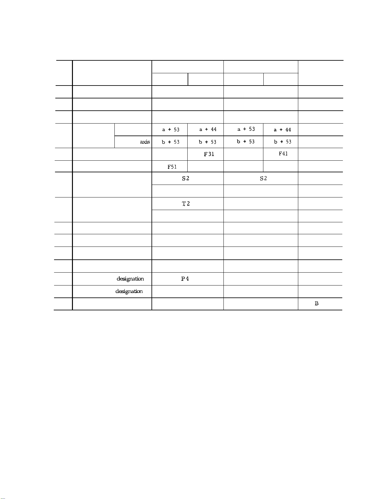
Table 2.1 Input Format
No.
1
Program No.
2
Sequence No. N4 N4
3
G function
Cordinate
4
Word
5
Feed /rein
6
Feed/rein 1/10
7
S-function,
8
T- function
M–f unction
9
Tool Offset No. H20r D2
10
Address
Linear axis
Rotary
Metric Output
Metric Input
F50
Inch Input
04 04
G3
F32
S5
T4
M3
Inch Input
Metric Input Inch Input
G3 B
F50
F51
S5
T2
T4 o
M3
H2 or D2
F42
B: Basic
O: Optional
B
B
B
o
B
B
B
o
B
B
B
B-f unction
11
12
Dwell P53 P53
Program No. d&gnation
13
Sequence No. dkgnaticm
14
15
No. of repetitions
B3
P4
L8 L8
B3
P4
o
B
B
B
Page 11

2.1.2 ADDRESS AND FUNCTION CHARACTERS
Address characters and their meanings are shown in Table 2.2.
Table 2.2 Address Characters
Address
Characters
A Additional rotary axis parallel to X-axis
B
c
D
E
F
G
I
J
K
L Number of repetitions
M
Additional rotary axis parallel to Y-axis
Additional rotary axis parallel to Z-axis
Tool radius offset number
User macro character
Feedrate
1
Tool length offset number
X-coordinate of arc center
Radius for circle cutting
Y-coordinate of arc center
Cutting depth for circle cutting
Z-coordinate arc center
Miscellaneous functions
ory function
Meanings
Basic
O: Optional
o
I
o
o
o
B
B, O
B
o
B
B, O
N
Sequence number
‘umber
P
Q
R
s
T
u Additional linear axis parallel to X-axis
v Additional linear axis parallel to Y-axis
w
x
Y
z
Dwell time, Program No. and sequence No.
designation in subprogram
Depth of cut,
Point R for canned cycles
Radius designation of a circular arc
Spindle-speed function
shift of canned cycles
I
Tool function
I
Additional linear axis parallel to Z-axis o
X-coordinate
Y-coordinate
Z-coordinate
I
B
B
o
o
O, B
B
B
o
o
I
B
B
B
3
Page 12
2.1.2 ADDRESS AND FUNCTION CHARACTERS (Cent’d)
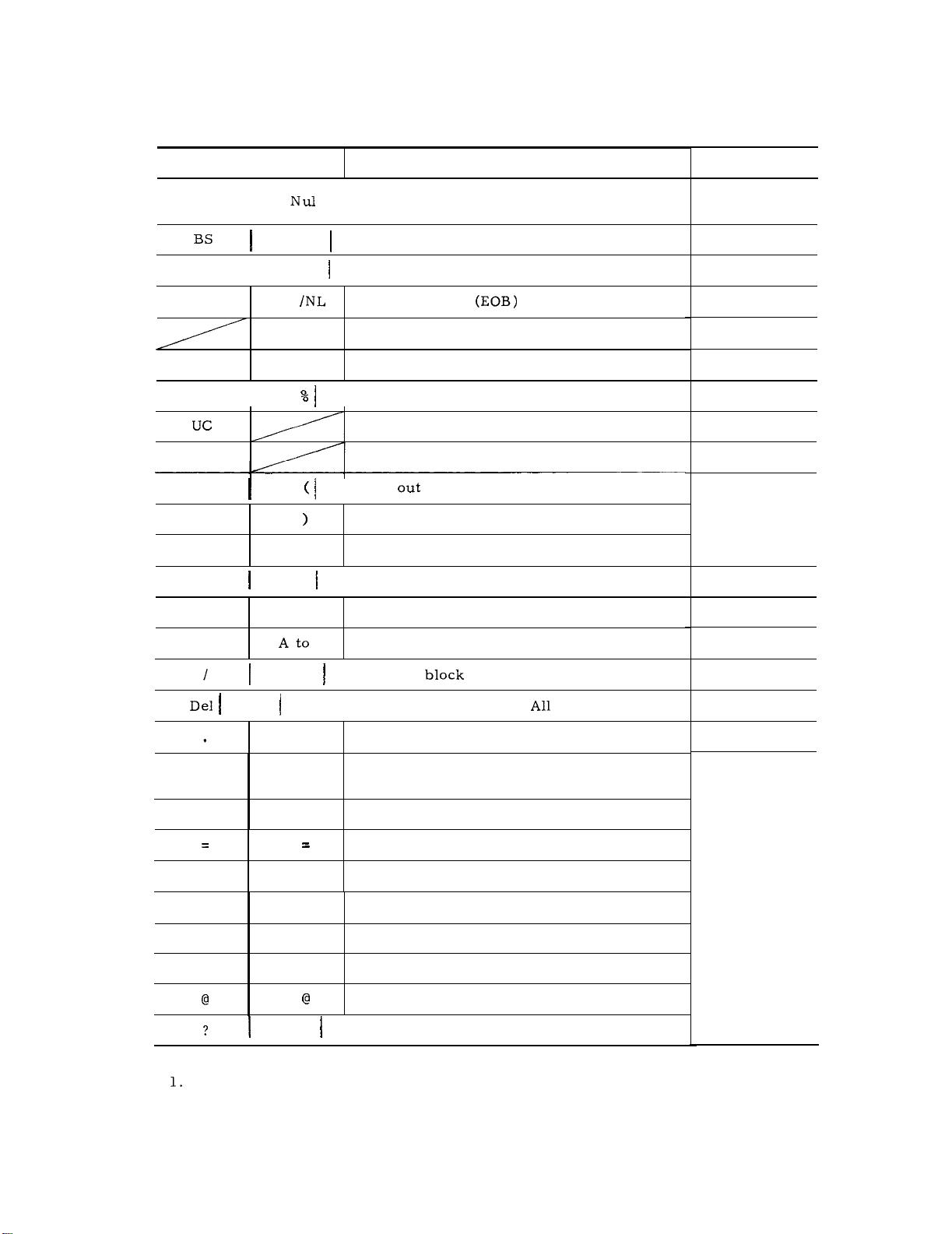
Table 2.3 Function Characters
EIA Code
Blank
Tab
CR
SP SP Space
ER
LC
2-4-5 bits
ISO Code
I
I
BS
HT
I
LF
CR Disregarded
I
I
Disregarded
Disregarded
Rewind stop
Control
2-4-7 bits
•!-
oto9
+
-
Minus sign, User macro operator
oto9
Meanings
Error in significant data area in EIA
Disregarded in ISO
End of Block
Upper shift
Lower shift
(Comment start)
Control in (Comment end)
Disregarded, User macro operator
Numerals
Remarks
EIA :
Special
code
atoz
DEL
Parameter
setting
*
[
1
o
$
Notes:
Characters other than the above cause error in significant data area.
Information between Control Out and Control In is ignored as insignificant data.
2.
Tape code (EIA or 1S0) can be switched by setting.
3.
Z
/
Optional
Disregarded (Including
#
*
[
1
$
?
User macro operator
Address characters, User macro operator
skip
Mark)
Decimal point
I
Sharp (Variable)
Astrisk (Multiplication operator)
Equal mark
Left bracket
Right bracket
User macro operator
User macro operator
User macro operator
EIA:
Special
code
4
Page 13
2.1.3 DECIMAL POINT PROGRAMMING
Numerals containing a decimal point may be used
as the dimensional data of addresses related to
coordinates (distance) , time and speed.
Decimal points can be used in the following address words.
Coordinate words: X, Y, Z, I, J, K, A, B,C,
U, V, W, Q, R
Time word: P
Feed rate word: F
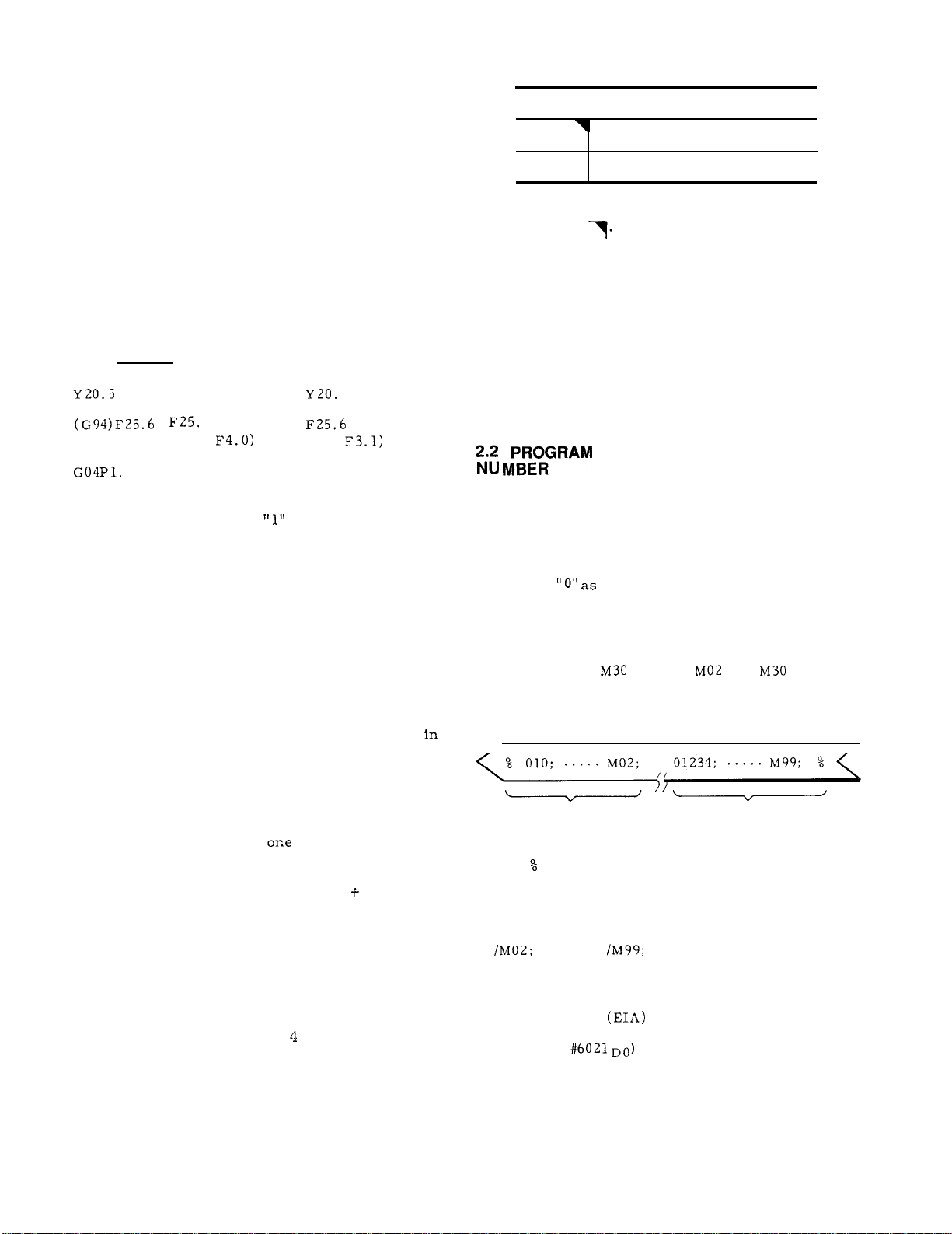
EXAMPLE
[ mm]
X15. X15.000 mm
— Y20. 500 mm
– F25. O mm/min or
(for
Dwell 1.000 sec
[inch]
x15.0000 inches
or
or
5000 inches
inches/rein
(for
M code
M 92
M93
Note: When power is applied or the control is
reset, the control is in the state of M code
marked with
Inter-block stoppage can be eliminated when the
program is so made that the automatic operation
time of advance reading of 4 blocks is longer than
processing time of advance reading of next 4
blocks of data.
Note :
Advance reading is not made for every 4 blocks
but is always ready to be made up to 4 blocks in
M93 mode.
I
Multi-active register off
Multi-active register on
NUMBER AND SEQUENCE
Meaning
Normally, when data without a decimal point is
input, the control regards
(or 0.0001 inches, or 0.001 deg.).
as O. 001 mm
2.1.4 LABEL SKIP FUNCTION
In the cases named below,
becomes effective , and LSK is displayed on the
CRT.
. When the power supply is turned on.
. When the RESET key is pushed.
While the label skip function is effective, all data
on the punched tape up to the first EOB code are
neglected. When LSK is displayed on the CRT
the MEM (memory) or EDIT (editing) mode , it indicates the presence of a pointer at the leading
end of the part program.
BUFFER REGISTER
2.1.5
During normal operation ,
read in advance and compensation computing is
made for the follow-on operation.
In the tool radius compensation C
blocks of data or up to 4 blocks of data are read
in advance and compensation computing required
for the next operation is executed. One block can
contain up to 128 characters including EOB .
2.1.6 MULTI-ACTIVE REGISTERS
For the portion of part programs sandwiched in
between M93 and M92, up to
read in advance.
the label skip function
block of data is
mode, two
t
blocks of data are
2.2.1 PROGRAM NUMBER
Program numbers may be prefixed to programs
for the purpose of program identification.
Up to 4 digits may be written after an address
character
program numbers can be registered in the control, and up to 199 or 999 can be registered
employing an option.
One program begins with a program number, and
ends with M02,
placed at the ends of main programs, and M99 is
placed at the ends of subprograms.
PROGRAM WITH
PROGRAM NO. 10
ER (or
the top and end of the program.
Notes :
The blocks for optional block skip such as
of programs .
. To make the reading of M02, M30, and M99 in-
effective as a program end, and to make the
succeeding ER
program ends is possible with a parameter
change. (
as program numbers.
or M99.
PROGRAM WITH
PROGRAM NO. 1234
at ISO code) is punched on the tape at
, /M30; ,
are not regarded as ends
or % (I SO) as a sign of
and
up to 99
are
5
Page 14
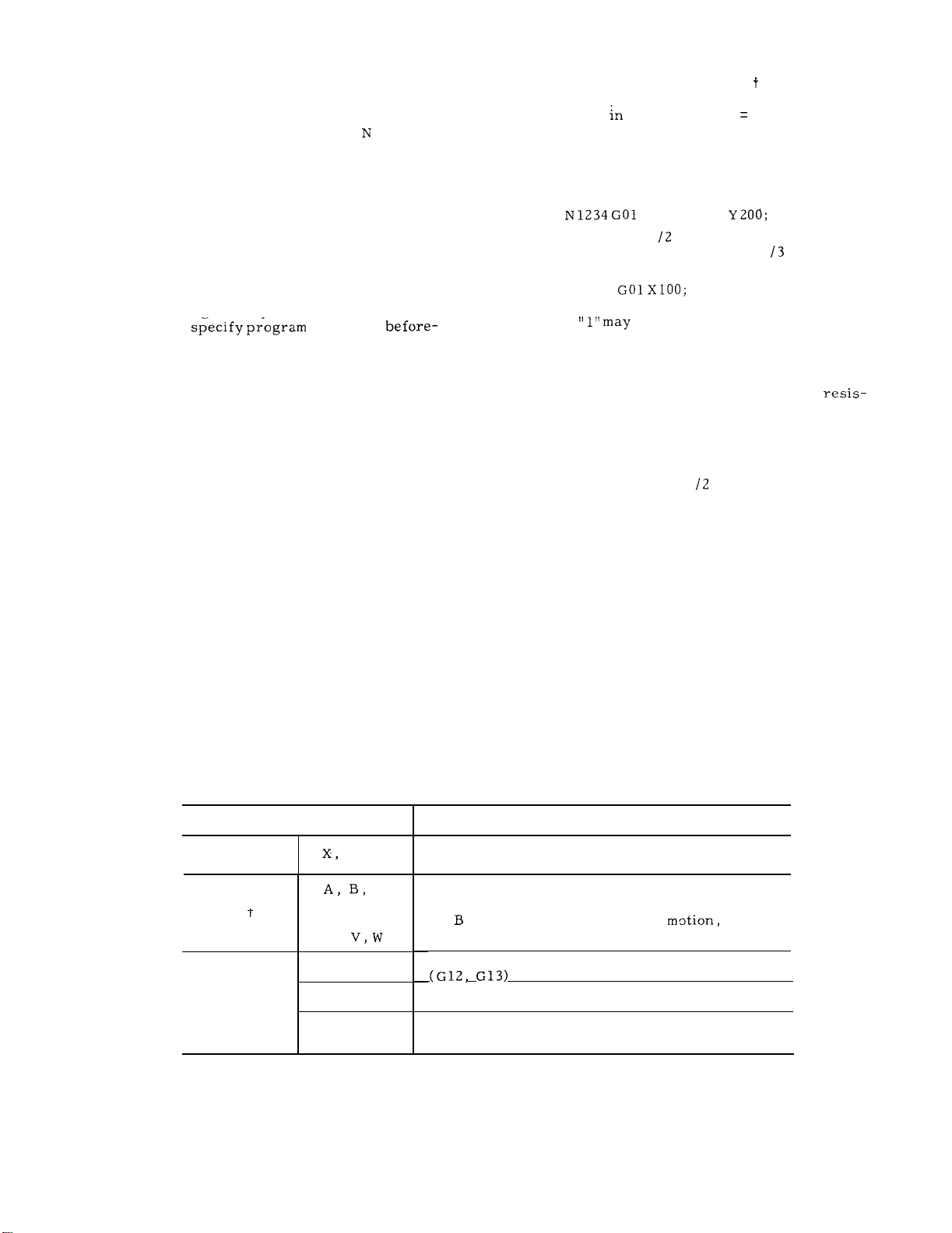
2.2.2 SEQUENCE NUMBER
2.2.3 OPTIONAL BLOCK SKIP (/1 - /9)
Integers consisting of up to 4 digits may be written following an address character
numbers.
Sequence numbers are reference numbers for
blocks, and do not have any influence on the
meaning and sequence of machining processes.
Therefore, they may be sequential, non-sequen-
tial, and duplicated numbers, and also not using
any sequence number is also possible. Generally,
sequential numbers are convenient as sequence
numbers.
When searching for sequence numbers, be sure
to search or
hand.
Notes :
. When 5 or more digits are written as
number, only the digits up to the 4th from the
trailing end are effective.
. When two or more blocks have the same sequence
number, only one is retrieved and read, and
no more searching is performed.
Blocks without sequence numbers can also be
searched for with respect to the address data
contained in the blocks.
numbers
as sequence
a sequence
Those blocks
ed are neglected between In and the end of that
block, when the external optional block skip
switch for that number “n” is on.
EXAMPLE
/2
When the switch for
neglected,
block is read as if
With “ 1“ ,
Notes :
The optional block skipping process is executed
while the blocks are read into the buffer
ter.
switching on is ineffective to skip the blocks.
While reading or punching out programs, this
function is ineffective.
The optional block skip
function.
and when the switch for
N 1234
If the blocks have been read , subsequent
X1OO /3 Y20();
is on , the entire block is
XIOO; .
may be omitted.
1 - 9) is includ-
is on , this
- /9 is an option
2.3 COORDINATE WORD
Generally,
tions and commands for setting coordinate systems are called coordinate words, and coordinate
words consist of address characters for desired
axes and numerals representing dimensions of
directions.
2.3.1 COORDINATE WORD
commands for movements in axis direc-
Table 2.4 Coordinate Words
Address
Main axes
4th axis
Circular
interpolation
auxiliary
data
Y, z
or
u,
Q
R
I, J, K
C
Position or distance in X, Y or Z coordinate
direction.
These coordinate words are treated as commands
in the directions of the 4th axis.
A ,
U , V and W are used for parallel motion
Circular arc increment in circle cutting
Generally,
Generally, distances from start point to arc
center (in X , Y and Z components) .
Description
and C are used for rotary m~tion, and
G13)
radius values of circles.
6
Page 15
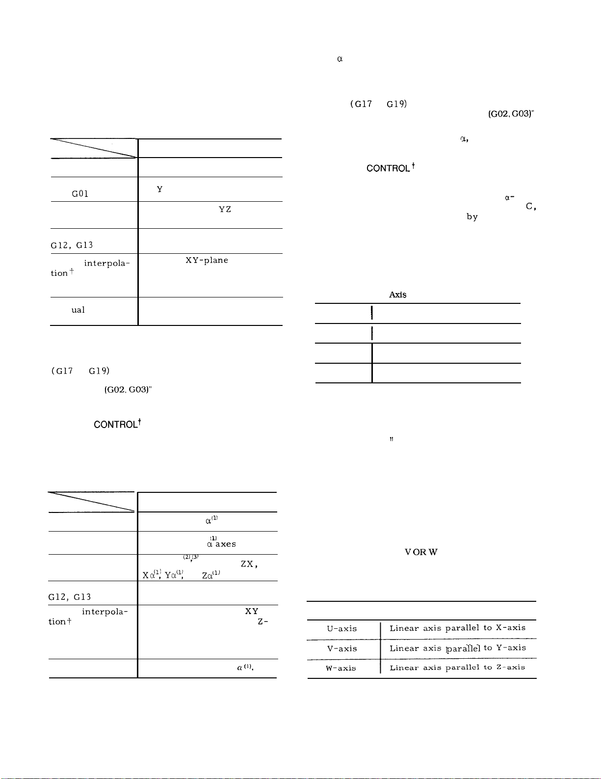
2.3.2 SIMULTANEOUSLY CONTROLLABLE AXES OF
THREE-AXIS CONTROL
Table 2. 5 shows simultaneously controllable
axes.
Table 2.5 Simultaneously Controllable Axes of
Positioning GOO
Linear interpola-
tion
Circular inter-
polation G02, G03
Circle cutting+
Helical
G02, G03
Man
Three-axis Control
Simultaneously
controllable axes
X, Y and Z axes
X,
Two axes:
Two axes: X and Y
Circle in
feed in Z-axis direction .
Refer to 2. 9.5 HELICAL
INTERPOLATION .
X. Y and Z
XY,
(see Note. )
or ZX
and linear
(1) The
U, V or W, selected as the 4th axis.
(2) Circular arc plane is determined according to
the currently effective G codes for plane desig-
nation
2.9.4, “ CIRCULAR INTERPOLATION
on page 22.
(3) For circular interpolation axis
linear axes U, V , and W should be designated.
2.3.4 4TH
An additional 4th axis can be incorporated. In
this manual, the 4th axis is referred to as
axis, and represents any of the 6 axes, A, B,
U, V and W.
#6023.
2.3.4.1 ROTARY AXIS (A, B OR C AXIS)
The rotary axis is defined as follows.
AXIS CONTROLt
Rotary axis
Address. is specified
Table 2.7 Rotary Axes for 4th
Control Table
Definition
parameter
Note:
Circular arc plane is determined according to the
currently effective G codes for plane designation.
For details, refer to 2.9.4, “ CIRCULAR INTERPOLATION
SIMULTANEOUSLY CONTROLLABLE AXES OF
2.3.3
FOUR-AXIS
Table 2. 6 shows simultaneously controllable
axes.
Table 2.6 Simultaneously Controllable Axes of
Positioning GOO
Linear interpola-
tion GO 1
Circular inter-
polation G02, G03
Circular cuttingt
Helical
G02, G03
Manual control
Four-axis Control
Simultaneously
controllable axes
X, Y, Z, and
X, Y, Z , and
Two axes,
Two axes: X and Y
Three axes :
plane and linear feed in
axis direction.
2. 9.5 HELICAL INTERPO-
LATION on page 27.
Four axes, X, Y, Z, or
XY, Yz,
circle in
-
Refer tc
A axis
B axis Rotary axis parallel to Y-axis
C axis
Note:
The unit of output increment and input increment
for B-axis is “deg.
linear axes. For the other respects, the treatments are the same as those in mm.
system)
Even when inch system is selected by parameter,
the values for the B- axis remains
The control does not convert B-axis coordinate
commands.
converted. (Refer to 2.9.3. “ LINEAR INTERPOLATION”)
2.3.4.2 LINEAR AXIS (U,
The linear axes are defined as follows.
Linear axis
Rotary axis parallel to X-axis
Rotary axis parallel to Z-axis
In this manual, any one of the three
axes, A, B and C, is referred to as
B-axis .
instead of “mm” used with
(Metric
“deg. “ unit.
However, feedrate command F is
OR
AXIS)
Table 2.8 Linear Axes
I
Linear axis parallel to X-axis
Linear axis
Linear axis parallel to Z-axis
Definition
to Y-axis
Note:
In this manual, linear axes either U, V
or W are indicated by c-axis.
7
Page 16
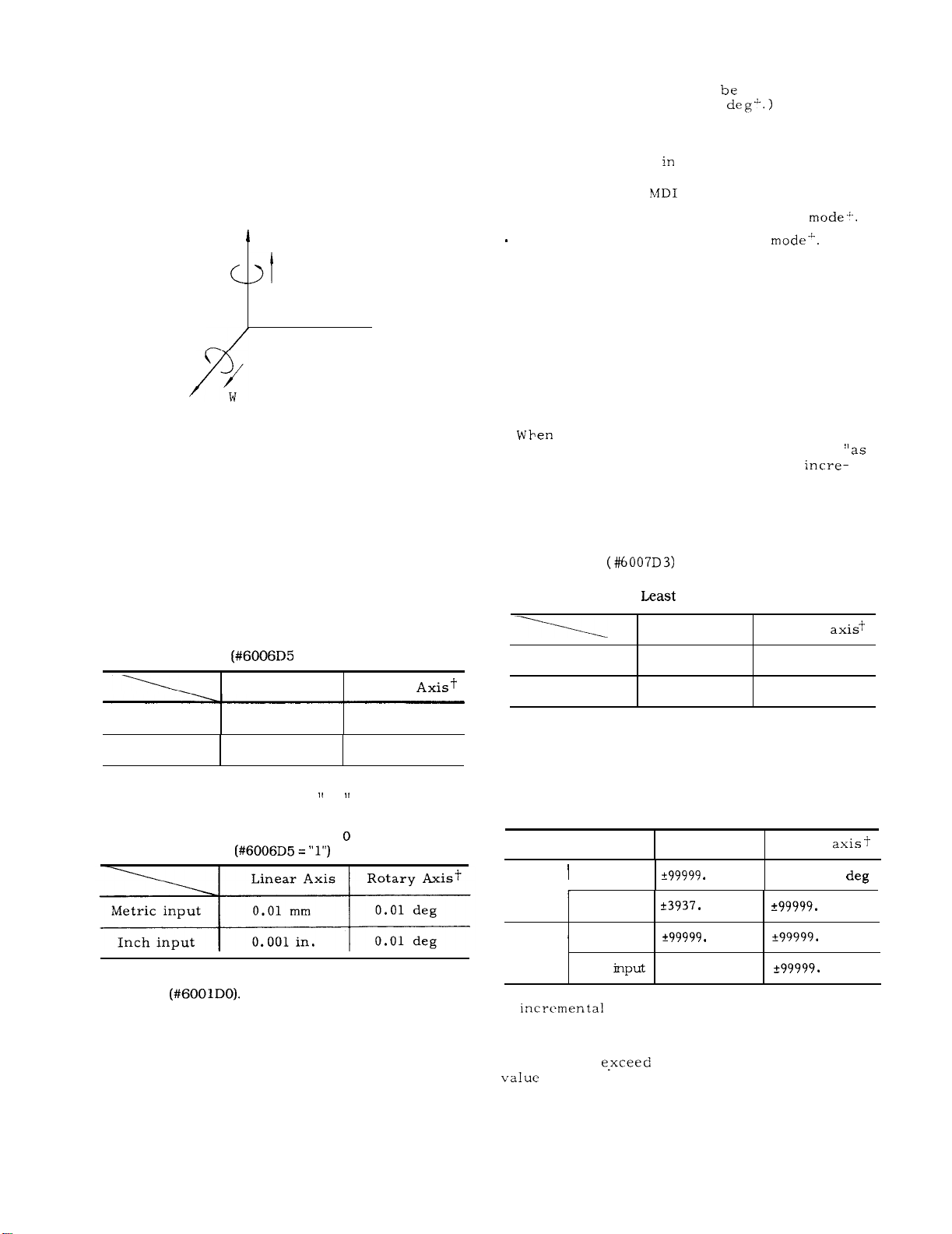
2.3.4.2 LINEAR AXIS (U, V OR W AXIS) (Cent’d)
The unit output increment and input increment for
C-axis is the same as the other linear axes, X, Y
and Z. No discrimination is necessary.
When inch system is selected by parameter, input
values must be in inches for C–axis.
Y
v
B
—u
-x
c
A
z
Tool offset value must always
mm (or 0.0001 inch, or 0.001
is possible in these units.
In 0.01 mm increment system, the following op-
eration must be made
. Write operation in
. Programming for operation in MEMORY
Program editing operation in EDT
Notes :
If NC programs set by O. 001 mm is fed into or stored in an equipment set by 0.01 mm
increment, the machine will move ten times
the intended dimensions.
If the increment system is switched when the
contents of NC tape are stored in memory, the
machine will move by ten times or one tenth of
the commanded dimensions .
the unit of O. 01 mm.
, and offset
Fig. 2.1 4th Axis in Right-hand
Coordinate System
LEAST INPUT INCREMENT AND LEAST OUTPUT
2.3.5
INCREMENT
2.3.5.1 LEAST INPUT INCREMENT
The minimum input units that can be commanded
by punched tape or MDI are shown in Table
2.9.
Table 2.9 Least Input Increment
Linear Axis
Metric input
Inch input
Least input increment times ten can be set by
setting parameter #6006D5 at
O. 001 mm
0.0001 in
Input Increment X 1
Rotary
0.001 deg
O. 001 deg
1.
tape-’ ,
stored” regardless of switching of the
ment system.
2.3.5.2 LEAST OUTPUT INCREMENT
Least output increment is the minimum unit of tool
motion.
by parameter
Metric output
Inch output
2.3.6
Maximum programmable dimensions of move com-
mand are shown below.
Table 2.11 Maximum Programmable Dimensions
Metric
output
the stored figures are punched out
Selection of metric or inch output is made
Table 2.10
Output Increment
Linear axis
0.001 mm 0.001 deg
0.0001 in.
Rotary
0.001 deg
MAXIMUM PROGRAMMABLE DIMENSIONS
Rotary
!
*99999.999 deg
Metric input
Inch input
Linear axis
999 mm
0078 in.
999 deg
Note : Selection of metric system or inch system is made
by setting
8
Inch
output
In
not exceed the maximum programmable value.
In absolute programming , move amount of each
axis must not
Metric input
Inch
the maximum programmable
999 mm
*9999.9999 in.
999 deg
999 deg
Page 17
:
The machine may not function properly if
a move command over the maximum programmable
value is given The above maximum program-
mable values also
dresses I, J, K, R, Q
mand addresses X , Y, Z ,
The accumulative value must not exceed the maximum accumulative values shown below .
Table 2.12 Maximum Cumulative values
to distance command ad-
Table 2.13 Programmable Range of Feedrate
(Feed/rein) range
F1.-F3OOOO.O mm/min
Metric
output
Inch
output
Metric input
Inch input
Metric input
Inch
F50
FO.1-F1181.1O in. /rein
F31
F50
FO. 1-3000.00 in. /rein
F31
Feedrate
mm/min
Linear axis
Metric input
Inch input
Listed input values do not depend on metric/
inch output system.
99999.999 mm
9999.9999 in.
Rotary
99999.999 deg
99999.999 deg
2.4 TRAVERSE AND FEED FUNCTIONS
2.4.1 RAPID TRAVERSE RATE
2. 4.1.1 RAPID TRAVERSE RATE
The rapid traverse motion is used for the motion
for the Positioning
the Manual Rapid Traverse (RAPID) . The traverse rates differ among the axes since they are
dependent on the machine specification and are
determined by the machine tool builders. The
rapid traverse rates determined by the machine
are set by parameters in advance for individual
axes.
in two or three axial directions simultaneously ,
motions in these axial directions are independent
of each other, and
different times among these motions. Therefore,
motion paths are normally not straight.
For override rapid traverse rates , Fo, 25%, 50%
and 100% of the basic rapid traverse rates , are
available.
parameter ( #6231) .
2. 4.1.2 SETTING RANGE OF RAPID TRAVERSE
RATE
For each axis, rapid traverse rates can be set
at some suitable multiple of O. 001
min ) .
The maximum programmable rapid traverse rate is
30,000
have their own optimum rapid traverse rates. Refer to
the manual provided by the machine tool builder.
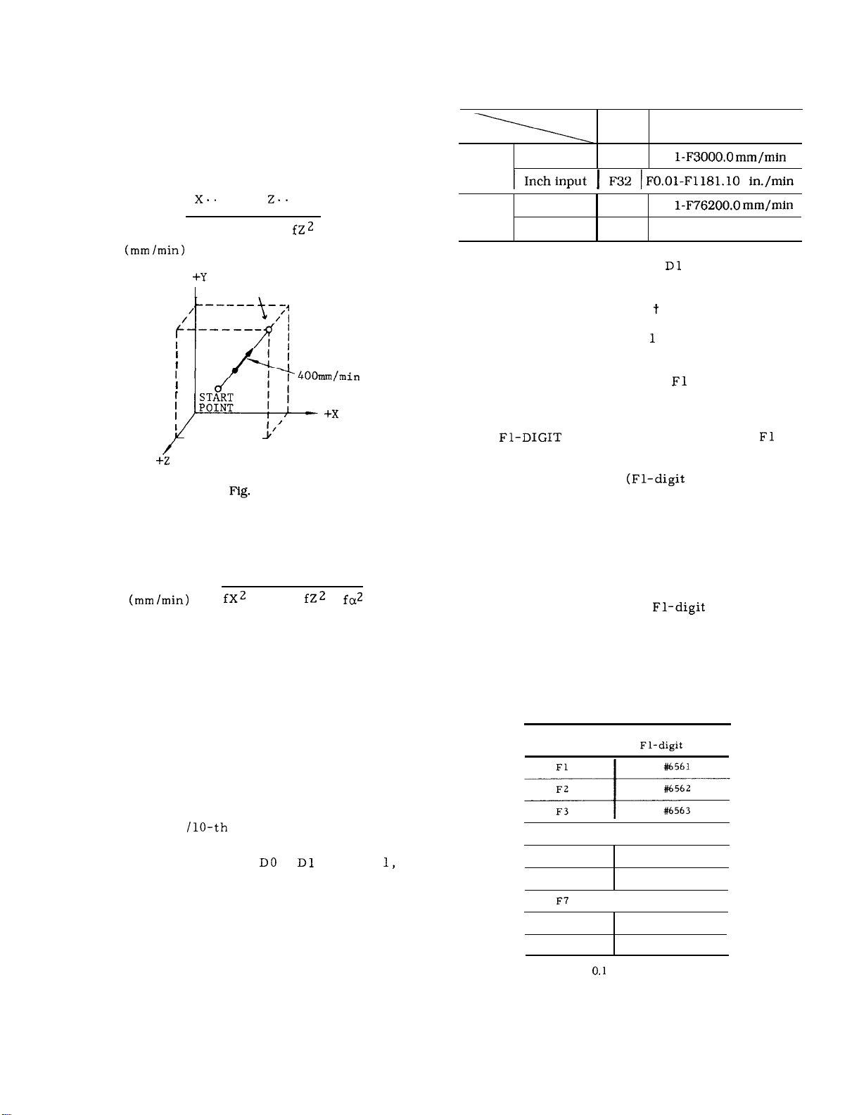
2.4.2
With five digits following an address character F,
tool feedrates per minute (mm /rein) are programmed.
The programmable range of feedrates is as follows.
When the tool is moved in rapid traverse
Fo is a constant feed rate set by a
FEEDRATE (F-FUNCTION)
and for the motion for
(or deg /
The maximum feedrate is subject to the perform-
ance of the servo system and the machine system.
When the maximum feedrate set by the servo or
machine system is below the maximum programmable feedrate given above, the former is set by
a parameter ( #6228) , and whenever feedrates
feedrate is clamped at the set maximum value.
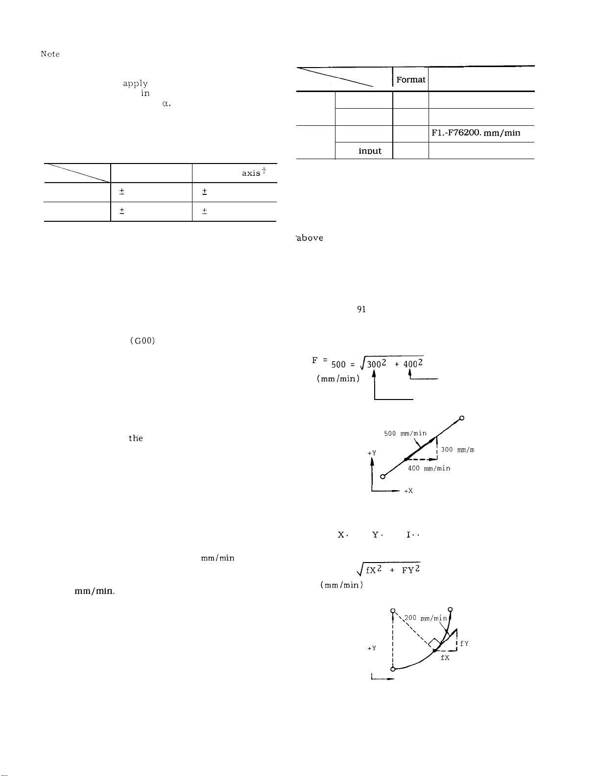
F commands for linear and circular interpolations
involving motions in simultaneously controlled
two axial directions specify feedrates in the direc-
tion tangential to the motion path.
EXAMPLE G
GO1 X40.
With this command,
G03
With this command,
F = 200 =
(incremental)
Y30.
500 nun/rein
. . .
. . .
CENTER
I
F500
400
Fig. 2.2
\
.,200
I
I
l\
+x
Fig. 2.3
X component
Y component
, 300
. F200
\
in
9
Page 18
2.4.2
FEEDRATE (F-FUNCTION) (Cent’d)
F commands for linear interpolations involving
motions in simultaneously controlled three axial
directions specify feedrates also in the direction
tangential to the motion path.
EXAMPLE
With GO1
F = 400 = fX2 + fY2 +
. Y.. .
. F400 ;
Metric
output
Inch
output
Table 2.14 Programmable Range
of 1/10 Feedrate
Format
Metric input
~nchinput
Metric input
Inch input
F51
FO.
F32 IFO.01-FI.IBI.10 in./min
F51
FO.
F32
F0.01-F3000.00 in. /rein
Feedrate
(Feed/rein) range
END POINT
—— —____
2.4
F commands for linear interpolations involving
motions in simultaneously controlled four axial
directions specify feedrates also in the direction
tangential to the motion path.
F
Notes :
. If FO is programmed, it is regarded as a data
error. (alarm code “030)
. Do not program F commands with minus numerals,
otherwise correct operation is not guaranteed.
EXAMPLE
F-250 ; . . . . . . . . wrong
+ fy2 +
+ fa2
. When parameter #6020 DO or
the feedrate range returns to normal.
is set to “O, ”
2.4.4 F 1-DIGIT PROGRAMMING
(1) Specification of a value
F selects the corresponding preset feedrate.
to 9 that follows
(2) Set the feedrate of each of F1 to F9 to the
setting number shown in Table 2.15 (a).
(3) By operating the manual pulse generator
when
digit command currently specified may be increased or decreased. Set the increment or decrement value per pulse
parameters listed in Table 2.15 (b).
As a result of this operation, the contents of the
setting number of the F1-digit feedrate are
changed.
(4) Upper Limit of Feedrate
Set the maximum feedrate of
to the following parameter. If a value greater
than the usual maximum feedrate (the contents
of #6228) is set, it is governed by the contents
of #6228.
switch is on, the feedrate of
multiply) to the
designation
Table 2.15 (a) F Command and
Setting No.
F command
Setting No. for
I
speed
-
2.4.3
FEEDRATE 1/1
The feedrate programmed by F commands can be
converted to 1
ting as follows.
. When parameter #6020
the feedrates range becomes as shown below.
O
or
is set to “
“
10
F4
F5
F6
FE
F9
Setting “ 1“ =
I
I
in. /rein or 0.01 in. /rein
#6564
#6565
#6566
#6567
#6568
#6569
Page 19
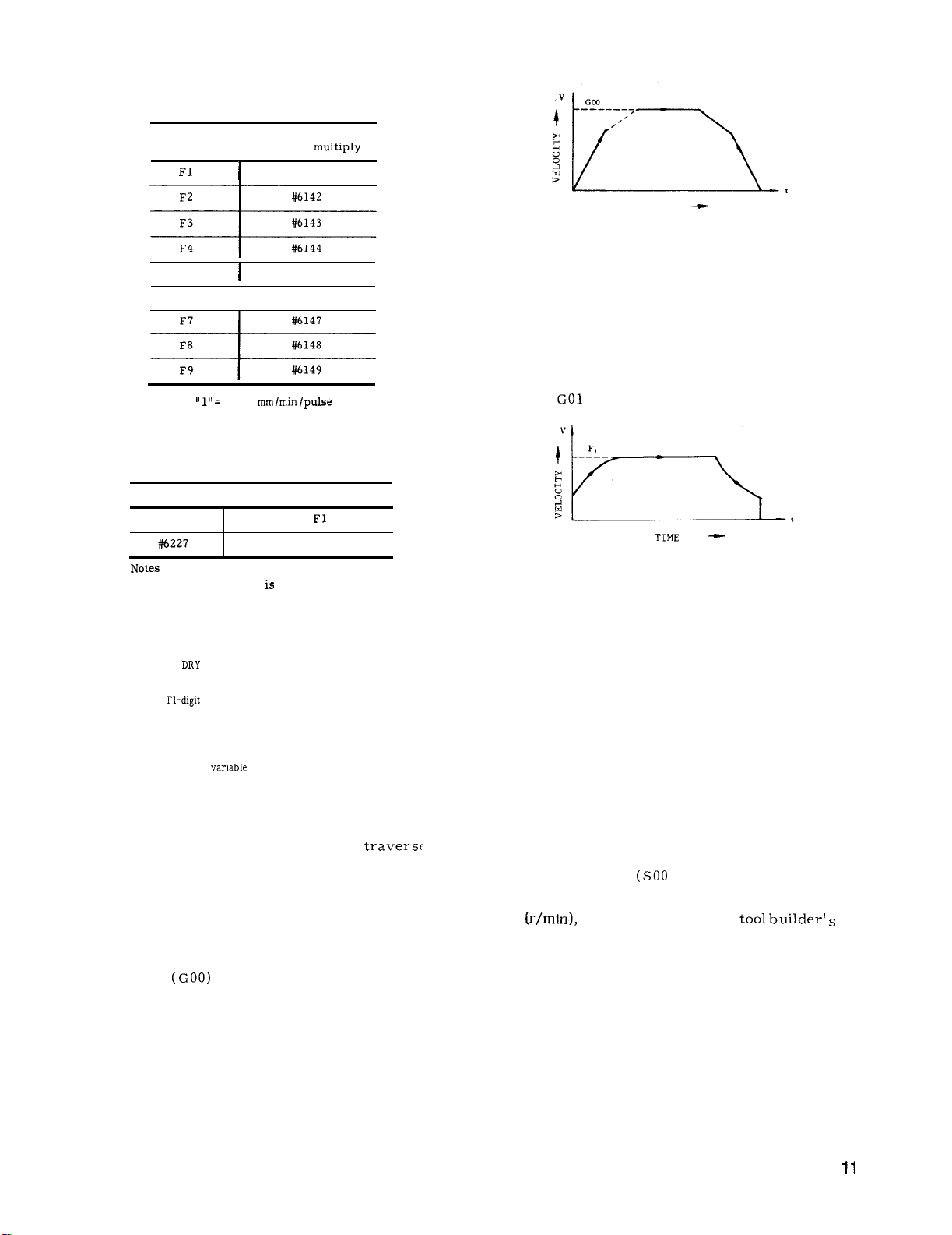
Table 2.15 (b) F Command and
Parameter No.
F
command
F5
F6
Setting
Parameter No.
a.
When this feature
1 to 9 mm /rein by the usual F function is not al-
lowed.
usually.
O.
Table 2.15 (c) Parameter No. for
Maximum Feedrate
#6226
:
Specifying
Parameter No. for
F1-digit
I
#6141
#6145
I
#6146
1
Meaning
I
Max speed of
Max speed of F5 to F9
installed, the specifying
to F4
10 mm /rein or more is allowed
b. If FO is specified, error “ 030”’ will be caused.
c. When
run is assumed.
d.
For
ride feature is invalid.
RUN switch is on, the rate of dry
specification, the feedrate over-
e. The feedrate stored in memory is retained
after the power is turned off.
For the
f.
command of micro-program
F l-digit command is possible.
2.4.5 AUTOMATIC ACCELERATION AND DECELERATION
Acceleration and deceleration for rapid
and cutting feed are automatically performed.
2.4.5.1 ACCELERATION AND DECELERATION
OF RAPID TRAVERSE AND MANUAL FEED
In the following operation , the pattern of auto-
matic acceleration and deceleration is linear .
. Positioning
. Manual rapid traverse (RAPID)
. Manual continuous feeding (JOG)
. Manual HANDLE feeding (HANDLE)
The 2-step linear acceleration/deceleration can be speci-
fied shown in Fig. 2.5.
TIME
Fig. 2.5
Rapid traverse rate and acceleration deceleration
constant of rapid traverse rate can be set by
parameter. (#6280 to #6301)
2.4.5.2 ACCELERATION /DECELERATION OF
FEEDRATE
Automatic acceleration and deceleration of feed
motion (
Feedrate time constants and feedrate bias are
set by parameters. During tapping, another time
constants and bias other than for usual feedrate
can be set by parameters (#6406 -#6434) .
- G03) are in the exponential mode.
Fig. 2.6 Exponential acceleration
deceleration
Note:
The automatic acceleration /deceleration param-
eters are set to the optimum values for the respective machines.
unless this is required for special purposes.
Do not change the setting
2.5 SPINDLE-SPEED FUNCTION (S-FUNCTION)
2.5.1 S 2-DIGIT PROGRAMMING
The spindle speed is specified by two digits following the address S
For each S code and its corresponding spindle
speed
manual.
When a move command and an S code are issued in the
same block, whether the S command is executed together with the move command or after the completion of tool
move depends on the machine tool builder. Refer to the
machine tool builder’s manual.
S codes are modal, remaining effective, when
once commanded, until next S code is commanded.
If the spindle is stopped by M05 (spindle stop)
command, the S command in the control is kept.
Page 20
2.5.1 S 2-DIGIT PROGRAMMING (Cent’d)
EXAMPLE
COO S11 M03 ;
. . . S command
Spindle CW
S11: Effective
Y.. . z.. . ;
Z.. . F.. . ;
GOO x.. .
Y.. . Z.. . M05 ; Spindle stop
M03 ;
x.. .
Y.. . z.. . ;
Z.. . F.. . ;
S22 ;
x.. .
Y.. . F.. . ;
Note : The two-digit BCD output is sent 10 the machine
when S two-digit command is issued.
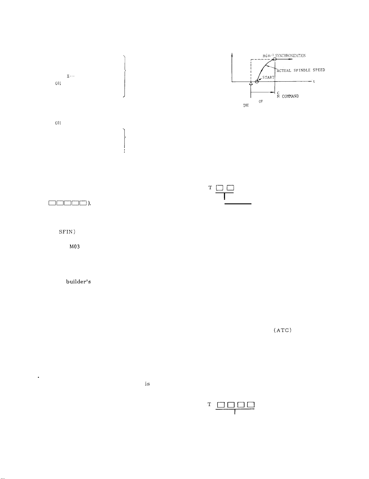
2.5.2 S 5-DIGIT PROGRAMMING
S11: Effective
1
S22: Effective
EXAMPLE
S 1000 M03 ;
s
1000
START
BLOCK
Fig. 2.7
SPEED
COMPLETION OF
2.6 TOOL FUNCTION (T-FUNCTION)
2.6.1 T 2-DIGIT PROGRAMMING
Two digits, following the address T , specify the
tool number.
Leading zeros may be omitted.
With five digits written after an address character
S(S
commanded.
The programmed speeds become effective upon
the inputting of an S-command-comple tion-inputsignal (
When an S command is programmed in the same
block with
(spindle reverse run) ,
block starts only after the spindle speed reaches
the level specified by the S command, in most
cases. However, for exact behavior of the machine tool under consideration, refer to the machine tool
The S commands are modal, and when it is programmed once,
command is programmed.
is stopped by M05, the S command remains effective.
again with an M03 (or M04) , the spindle runs at
the speed specified by the S command.
When the spindle speed is to be changed by a
new S command after it is started with an M03 or
M04, attention must be paid to the selected spindle speed range.
Notes :
The lower limit of programmable S commands
(SO and other S commands near O)
by the spindle motor of the machine tool. Refer
to the machine tool builder’s manual.
program minus values as S commands.
Therefore, when the spindle starts
spindle speeds (rein-l) are directly
,
(spindle forward run) or M04
the execution of the next
manual.
it remains effective until another
Even when the spindle
Do not
I
The figures used for the designation of tool num-
ber are determined by the machine. Refer to
the machine tool builder’s manual.
When a move command and a T code are issued
simultaneously ,
the two commands are executed simultaneously,
or
the T command is executed upon completion of
the execution of the move command,
depending on the design of the machine.
For this, refer to the machine builder’s manual.
T codes are modal, and therefore, once they
are given , they remain effective until another
T command is given.
T code commands are generally for making
automatic tool changers
tool number to be used next. Therefore, they
can be given without regard to the G, H “or D
codes which are for offsetting for the length
or radius of the tool currently in use.
2.6.2 T 4-DIGIT
Four digits following the address T specifies the
tool number.
Leading zeros may be omitted.
PROGRAMMING
Tool number
to select the
, When the control is equipped with the S 5-digit
command function ,
is possible. That is, override speeds between
50 and 120% of the commanded spindle speed
can be obtained at intervals of 10%.
spindle speed overriding
12
L Tool number
This tool code is the same as the T 2-digit codes,
except for the increased number of digits.
Page 21
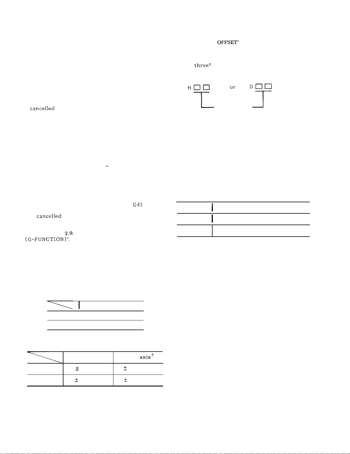
2.7 TOOL COMPENSATION
2.7.1 OUTLINE OF TOOL COMPENSATION
For the procedures of storing values into memory, refer
to 4.3.5.
SET AND WORK
“DISPLAYING AND WRITING OF TOOL OFF-
on page 144.
The tool compensation function is in the following
three modes.
. Tool length compensation
This function is for compensating the differences
in tool length, and is effective in the Z axis direction, Specified length compensation becomes
effective from the block in which G43 or G44 is
programmed together with an H code. It is
with HOO or G49.
. Tool position offset ( for simple compensation
for tool radius)
This function is for compensating for errors in
machined dimensions to be introduced by the radius
of tools. It is effective in the X, Y, and Z (4th t ) axis
directions.
G45-G48 is programmed together.
. Tool radius compensation C
for tool radius effects with complicated machining contours)
This function is for compensating for the tool
radius effect with any given machining contours.
It is effective in X-Y , Y-Z, and Z-X planes.
It becomes effective from the moment
G42 is commanded together with a D code, and
is
Not
e :
tions, refer to
It is effective only for the block in which
(for compensating
, or
by G40.
For details of these compensations func-
“PREPARATORY FUNCTION
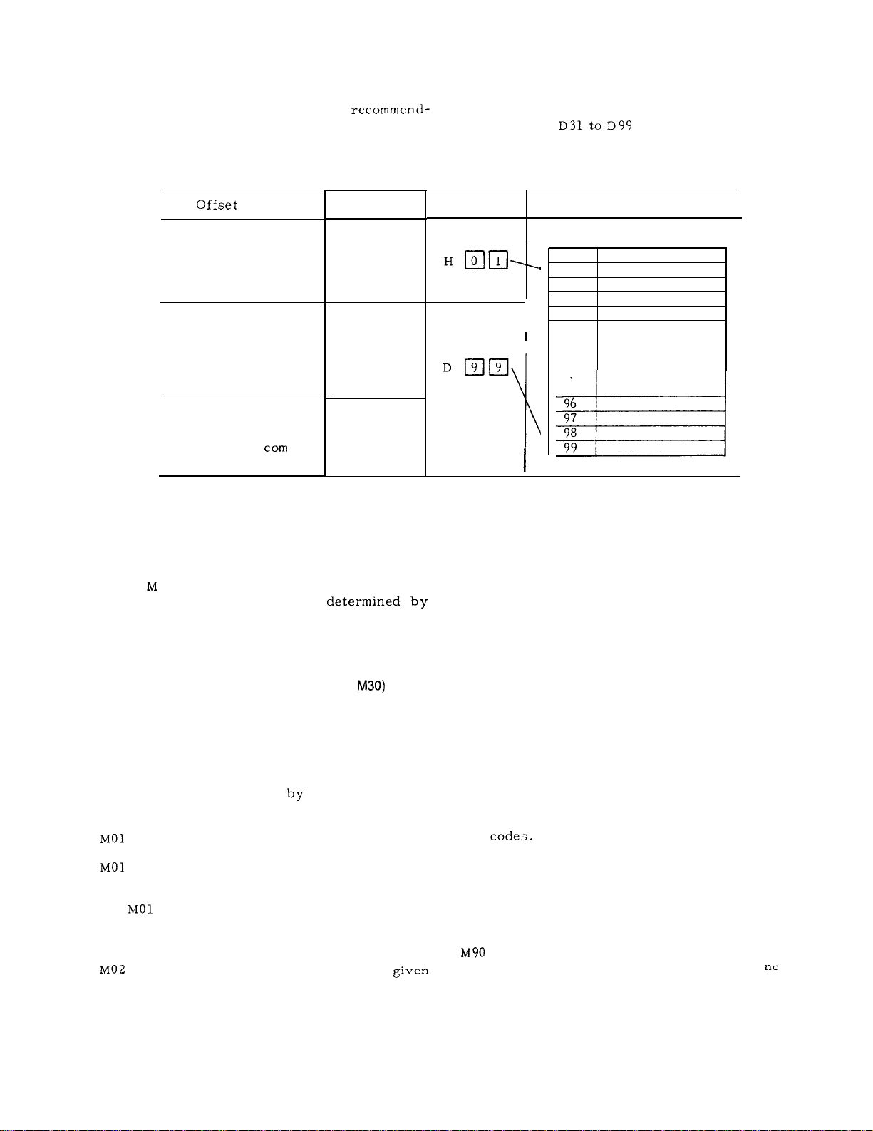
2.7.3 H- AND D-FUNCTION (H, D CODES)
Two or
D , specify tool offset numbers.
The tool offset numbers 01 through 99 directly
correspond to the
bers.
ignated, the corresponding g offset values stored
in the offset memories will be used to offset the
tools .
Tool offset numbers 00 (HOO or DOO) have differ-
ent meanings depending on the respective offset
functions. For details, refer to the descriptions
on the respective G functions.
H- and D-codes must be used properly according
to their functions.
That is, when certain numbers are des-
Code
H code
D code
digits, following the address H or
Tool offset
number
99 offset-value memory num-
Function
Tool length offset
1
Tool position offset, Tool radius
compensation
2.7.2 TOOL OFFSET MEMORY
For the three groups of offsets, all the necessary
offset values must be stored in memory before-
hand.
The following number of offset values can be
stored in the tool offset memory.
Offset Value Storage
Basic
t Optional
The setting range of offset values is as follows.
Metric input
Inch input
Listed input values do not depend on metric/
input output system.
I
I
Linear axis
999.999 mm
O -
O -
99
1199
Rotary
O-
999.999 deg
The tool offset numbers 01 through
used freely in combination with the both H and
D codes.
99 can be
13
Page 22
2.7.3 H- AND D-FUNCTION (H, D CODES) (Cent’d)
However, for programming ease, it is
ed to divide the numbers into H code part and
D code part.
Table 2.16 H or D Code and Offset Number
H codes:
D codes:
HO1 to H30
D99
method
Tool length offset
Tool position offset
Tool dia. compensation C
(Intersection
puting system)
-
G code
G43
G44
G49
G45
G46
G47
G48
G40
G41
G42
2.8 MISCELLANEOUS FUNCTIONS
(M-FUNCTION)
The miscellaneous function is specified with the
address
of each M code (MOO
the machine,
to the machine tool builder’s manual for the function of M codes except for the following M codes
concerned with the control.
2.8.1 M CODES FOR STOP (MOO, MO1 , M02,
MOO (Program Stop)
This code, when given in automatic operation
mode, stops the automatic operation after the
commands in the block containing MOO have
been completed and MOO R signal is fed. The
program may be continued
CYCLE START button.
stop MOO whenever the OPTIONAL STOP switch
is on.
the
M02 (End-of-Program)
in automatic operation
and maximum three digits. The function
to M89) is
except for several M codes.
pressing the
(Optional Stop)
performs the same function as program
When the OPTIONAL STOP switch is off,
code is disregarded.
is used at the end of program When
mode , this code stops
Refer
H or D code Offset value memory
No. Offset value
01
02
03
04
I
96
97
98
99
the automatic operation after the commands in
the block containing M02 have been completed.
Although the control is reset in most cases,
the details are determined by the machine. Refer to the machine tool builder’s manual.
M30 (End-of-Tape)
M30 is given at the end of tape. When given in
automatic operation mode, this code stops the
automatic operation after the commands in the
block containing M30 have been completed. In
addition, in most cases, the control is reset
and rewinds the memory.
are determined by the machine, refer to the
machine tool builder’s manual.
Notes :
. When MOO, MO1, M02 or M30 is given, it pre-
vents the control from reading ahead the next
block of information.
is fed in addition to the 2-digit BCD output for
M
. Whether MOO, MO1, M02 or M30 executes spin-
dle stop , coolant off or some other executions,
refer to the machine tool builder’s manual.
M CODES FOR INTERNAL PROCESSING
2.8.2
(M90 TO Ml 99)
through Ml 99 are used only for internal pro-
cessing.
Even when they are programmed ,
external output signal
is sent.
Since the details
The single decoded signal
(BIN and decoded output)
14
Page 23
M90t :
M94:
M95:
M
M98:
M99:
M1OO to 199: Used for enhansed codes
Program interrupt off
Program interrupt on
Multi-active register off
Multi-active register on
Mirror image off
Mirror image on
Tool radius compensation C:
circular path mode
Tool radius compensation C :
intersection computing mode
Subroutine program call
Subroutine program end
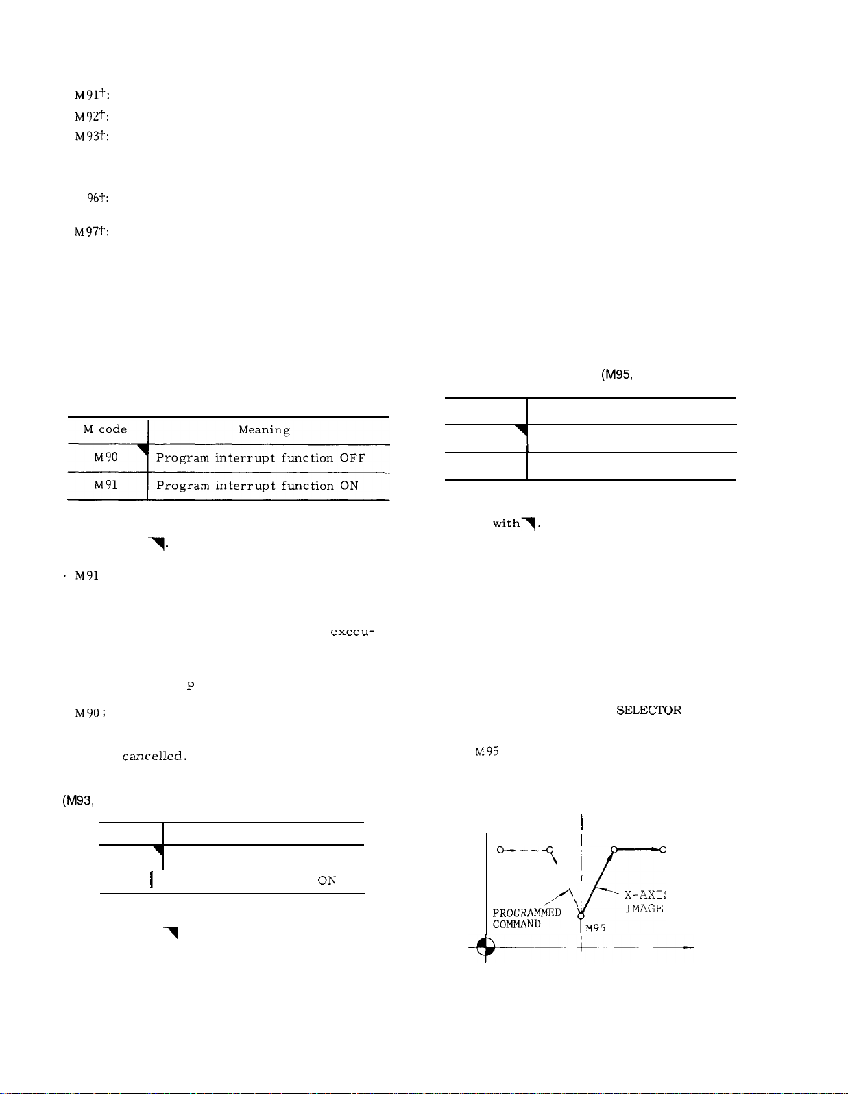
2.8.3 PROGRAM INTERRUPTION ON/OFF
(M91 , M90) t
M93:
During the time from this command to M92, the
control assumes the 4 blocks-advance-reading
mode.
in advance for the following operation.
the program is so made that the operation time
of advance reading of 4 blocks is longer than
processing time of advance reading of next 4
blocks of data.
M92:
This command cancels 4 blocks-advance -reading
mode.
Note :
blocks without move command can be contained( up to
two blocks ) .
cluding the two blocks, may be read in advance.
Namely, up to 4 blocks of data are read
Inter-block stoppage can be eliminated when
In tool radius compensation C mode, the
Under this condition, 6 blocks, in-
The following M codes are used for the program
interruption function .
Program interrupt function OFF
Note:
reset, the control is in the state of M code
marked with
.
When power is applied or the control is
P. . . . . . ;
During the time from this command to an M90
command, whenever a program interruption
signal is received, the program under
tion is interrupted (if the machine is in motion,
it is stopped after deceleration) , and the a jump
is made to the program the number of which is
written after the
With this command, the program interrupt func-
tion is
2.8.4 MULTI-ACTIVE REGISTERS ON/OFF
M92) t
M code
Meaning
MIRROR IMAGE ON/OFF
2.8.5
M code
M94
M95
Note: When power is applied or the control is
reset, the control is in the state of M code
marked
With these codes,
be started and stopped at any desired point in
the program.
made on a single block,
M94 and M95 are modal. When the power supply
is turned on, M94 (OFF) is in effect.
The axis on which mirror image is to be effected is
specified by setting #6000 Do to D3 (or mirror image
axis designation switch). For this procedure, refer to
5.1.25, “MIRROR IMAGE AXIS
on page 171.
When
control the machine in mirror-image fashion,
that is, movements in the specified coordinate
direction will be reversed.
Y
I
Mirror image OFF
Mirror image ON
mirror image operation can
These commands must always be
is given, the subsequent blocks will
M94)
Meaning
SWITCH”
M 92
M93
Note:
reset, the control is in the state of M code
marked with
When power is applied or the control is
Multi-active register OFF
Multi-active register ON
I
.
\
‘\
Fig. 2.8
X-AXIS MIRROR
IMAGE ON
M95
x
15
Page 24
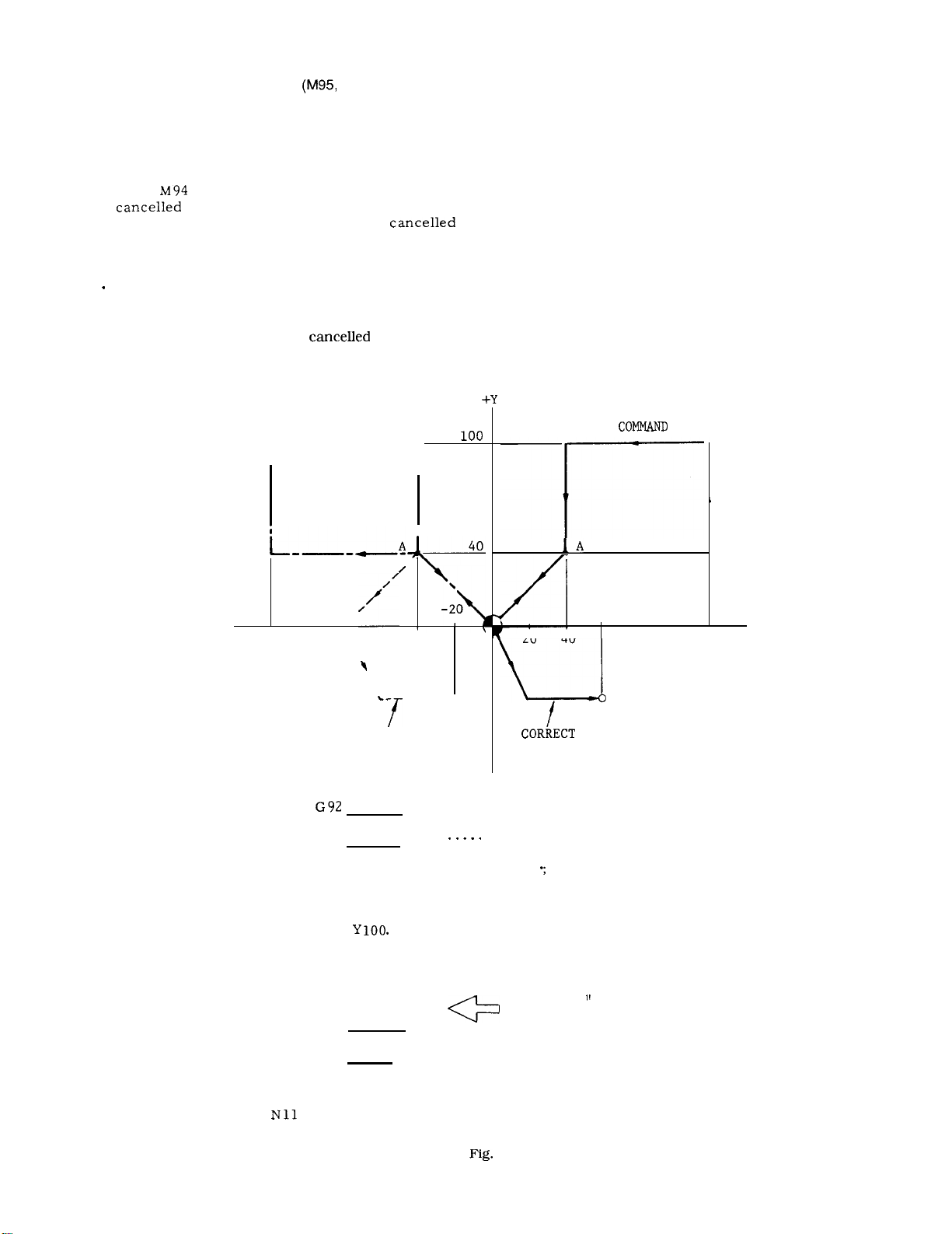
2.8.5 MIRROR IMAGE ON/OFF
With both the absolute and increment move
commands,
obtained.
constitutes the mirror point.
the same mirror image effect will be
The block including M95 command
M94) (Cent’d)
The mirror image effect is not effective on the
offset movement resulting from the tool length
offset function.
Do not switch the designation of mirror image
axis during operations under M95 (ON) mode,
. When
image operation must be started and
at the same position.
Notes :
When G28 or G30 is used to change tools or for
ending machining processes, make sure to cancel the
mirror image effect by means of M94.
If mirror image effect is not
G30 is given, an error “058” occurs.
EXAMPLE
is given , mirror image effect will be
on the subsequent blocks. Mirror
X AXIS MIRROR INAGE ON
-—-—-
-120
r
/
\
-80 \\
1
1
A’
/
\
\
\
-40
–––-90-40
\
STAR
POIN
Displayed current position by POS key in mirror image fashion indicates the actual motion of
Displayed data by COM key show program-
tool .
med commands,
. Program must be made so that mirror image
operation starts and stops at the same position.
If the start position and the stop position are
not the same, movements of the machine after
canceling mirror image will be shifted by the
difference between both positions.
PROGRAMMED
+x
20 40
60
120
16
PATH BY
ERRONEOUS
CANCELLING
NO1 G92 XO YO ;
N02
N03 G90 GO1 X40.
N04 X120. ;
N05
N06 X40. ;
N07
N08
N09’
N1O
M95 :
Y40. ;
Xo Yo ;
M94 ;
X20. Y-40. ;
x60. ;
Mirror image on.
Y40. F300
If “M94 ;
the tool moves on the dotted line.
. . . .
Correct mirror image off.
2.9
PATH
is programmed here,
Page 25
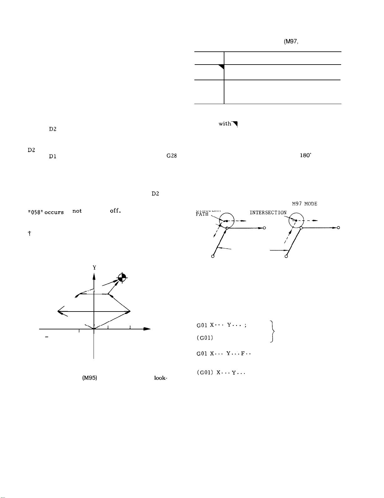
. Mirror image external input function
(a) Overview
In addition to the conventional mirror image
function, the mirror image execution mode can also
be set when power is turned on, or reset, by
setting the corresponding parameter.
mode is the mirror image execution mode (power on
or reset, ) the parameter can be set to select the
command mirror image at the G28 intermediate point
or not.
(b) How to use the function
(i) Upon power ON or upon reset
#6005,
(ii) Upon power ON, when it is M95 mode (#6005,
is “l.”)
#6005,
Note : The specifications are the same as the
conventional specifications, when #6005,
Therefore, turn off mirror image by M94, when
commanding G28, or G29 under this mode.
O: M94 mode (mirror image off)
1: M95 mode (mirror image on)
O: Commands mirror image at the
intermediate point
1: Does not command mirror image at
the G28 intermediate point
if not turned
When the
is “O. ”
Error
2.8.6 CIRCULAR PATH MODE ON/OFF ON
TOOL RADIUS COMPENSATION C
M code
M 96
M 97
Note:
reset, the control is in the state of M code
marked
In the G41 or G42 tool radius compensation mode,
when M96 is given, the tool moves along a circular
path around a corner with an angle of
In the M97 mode, the tool does not move along a
circular path at the corner, but moves along two
intersecting straight lines intersecting at a calculated
intersecting point shifted from the programmed
contour by the tool radius.
CIRCULAR
Tool radius compensation circular
path ON.
Tool radius compensation circular
path OFF.
(Execution of intersection point)
When power is applied or the control is
.
M96 MODE
Meaning
M96) t
or larger.
(c) Program example
Example of commanding mirror image on the G28
intermediate point
Program example (mirror image of X-axis only is
on)
REFERENCE POINT
X-AXIS MIRROR
IMAGE ON
,/”
-\.
I
100
Note : When commanding axis designation under the
mirror image mode
ahead by parameter (#61 16) of the set/reset M codes.
–40 o
‘
100
50
-
PROGRAM COMMAND
x
40
100
PROGRAMMED
CONTOUR
Fig. 2.10
M96 and M97 are modal. When the power is
turned on, M96 takes effect.
M 96 and M97 are effective on the following
move command blocks.
M96 (or M97) ;
FS. . ;
;
Effective from
the corner of
these 2 blocks
Effective from
the corner of
these 2 blocks
}
17
Page 26
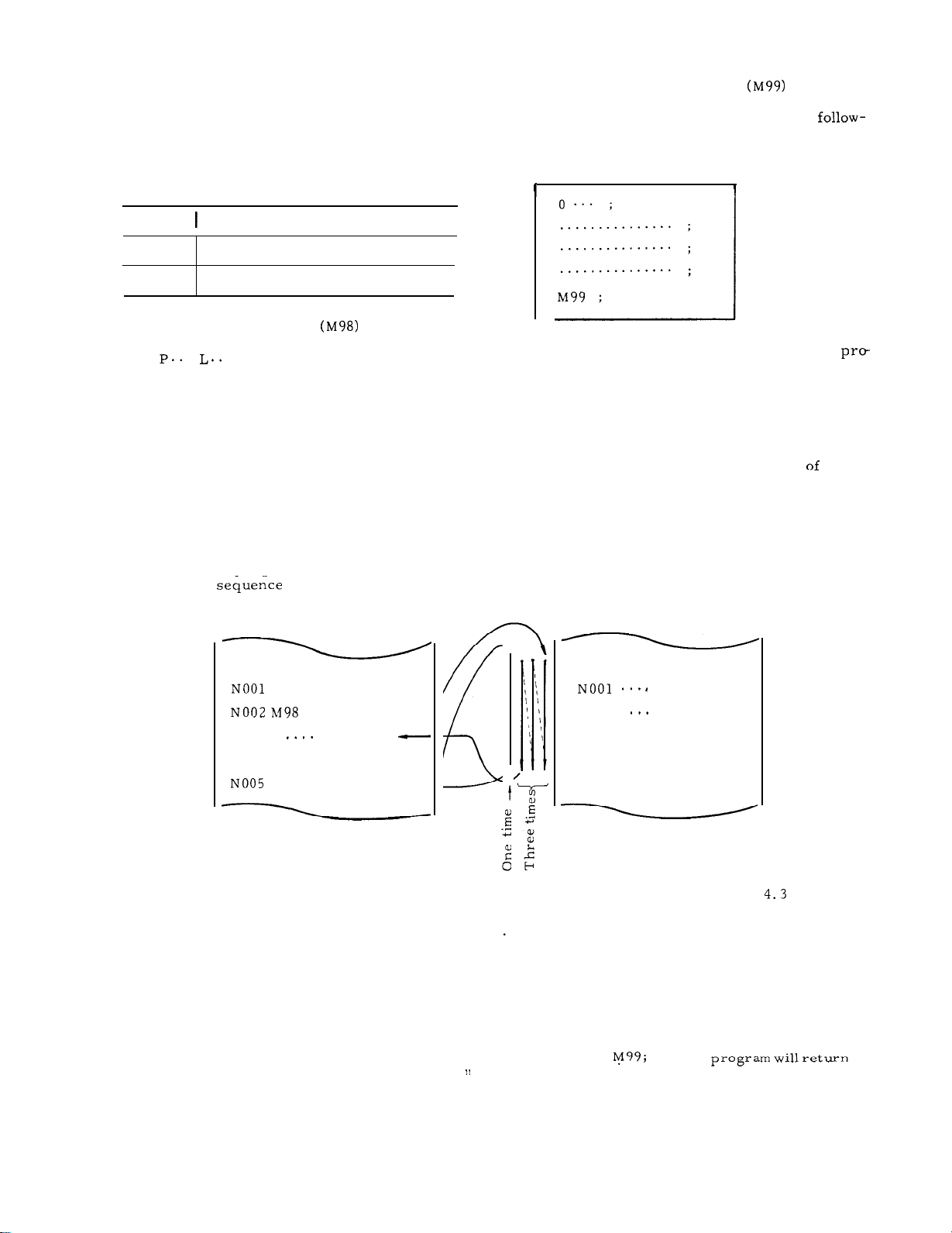
2.8.7 SUBROUTINE PROGRAM (M98, M99)
Format of subroutine program
With this function ,
which have been numbered and stored in advance
is made and executed as many times as desired.
The following M codes are used for this function.
M code
M98
M99
Call of subroutine program
M98
With this command, call of the subroutine pro-
gram with the number specified after P is made
and is executed number of times specified after
L.
routine is executed once.
Subroutine programs can be nested up to 4
times.
EXAMPLE
.
When no L code is programmed, the sub-
call of subroutine programs
Meaning
Call of subroutine program
Subroutine program end
. ;
Subroutine programs are written in the
in g format,
memory in advance.
o;
. . . . . . . . . . . . . . .;
. . . . . . . . . . . . . . .;
. . . . . . . . . . . . . . .;
Automatic return command from
gram
M99 ;
At the end of subroutine programs, M99 is
written in a block of its own.
commanded in the subroutine program which
has been called by M98, the execution
main program is automatically restarted at the
block immediately following the M98 block.
and are stored in the part program
. . .
;
—
Program No.
Subroutine
—
program end.
subroutine
When M99 is
the
Call of subroutine program and execution of it
are made in the
0100 ;
NO03
NO04 M98 P200 ; —
. Special use of M99
M99 P.. . ;
With this command,
return to the block following the M 98 block after
executing the subroutine program , but returns
to the block with a sequence No. specified by
the P code.
Notes :
If the program number specified by the P code
is not found, this
While a subroutine program is repeated L times,
the number of remaining repetitions may be
shown below.
Main program
GOO . . . . ;
P200 L3 ; –
;
. . . . ;
the main program does not
is regarded as an error “041.
Subroutine program
0200 ;
;
NO02
N050 M99 ;
displayed.
AND wRITING OPERATION .
This function is usable when subroutine pro-
grams are stored in the part program memory.
The main program can either be commanded
from NC tape or the part program memory.
When the nesting of subroutine programs is
attempted more than 4 times, an error state is
caused.
Commanding
the execution of the program to the head of the
main program and control endless operation.
. ;
For details , refer to
DISPLAY
18
Page 27
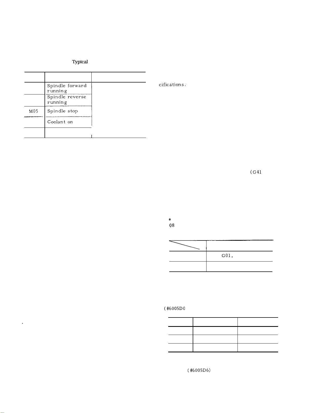
2.8.8 OTHER M CODES
For using M codes,
above,
ual.
When these M codes are given in the same block together
with move command, whether the M commands are
executed simultaneously or after completion of move
command, are determined by the type of machine. Refer
to the machine tool builder’s manual.
2.8.9 2ND MISCELLANEOUS FUNCTION
(B-FUNCTION)
Three digits following the address B give index
table positions.
The actual index positions corresponding to the
respective B codes depend on the machine tool
builder. For this, refer to the specifications of
the machine tool builder. When a B -function is
given together with a move command in one block,
. B command is executed after the execution of
depending on the design of the machine tool.
For this refer to the specifications of the ma-
chine tool builder.
B codes are modal.
it remains effective until another B-command is
given .
refer to the machine tool builder’s man-
Table 2.17
M code Meanings Remarks
M03
M04
M08
M09
the B command is executed simultaneously with
the move command, or
the move command,
Coolant off
I
t
other than those mentioned
Examples of
M Codes for Machine
M03 and M04 are
not switchable.
M05 (stop) must
be intermediated
I
When one B code is given,
Notes :
B function standard interface is in 3-digit BCD
output .
With MDI operation on NC panel, “B” is used to
specify address for B codes. Therefore, when the
control has B-function, the 4th axis control cannot be
added.
2.9 PREPARATORY FUNCTION (G-FUNCTION)
2.9.1 LIST OF G CODES AND GROUPS
An address character G and up to 3 digits following it specify the operation of the block.
Ordinary G codes are either non-modal G codes
marked with * or modal G codes belonging to
groups 01 through 15.
to the division B are included in the basic spe-
The G codes belonging to groups 01 through
15 are modal, remaining effective when once
commanded until other G codes in the same
group will be commanded.
The G codes in the * group are non-modal, and
are effective only for the block in which they
are commanded.
The G codes belonging to groups 01 through 15
may be programmed twice or more in the same
block.
same group are programmed, the last appearing G code is effective.
When the RESET key is depressed during the
execution of a tool compensation C
or a canned cycle, they become respectively
G40 or G80 which cancels the programmed commands.
G43, G44, G49 and G45 through G48 belonging
to the * group can be programmed together with
the following G codes in the 01 group in the
same block.
If
of
as G code of 08 group alarm will be caused.
The transition state of the following G codes
can be changed by setting of parameters.
The G codes belonging to the following groups
can be specified as to the state immediately
after the application of supply power.
However, when different G codes in the
group other than those G codes and G codes
group can be programmed in the same block
G43, G44, G49 GOO,
G45 - G48 GOO, GO1, G02, G03, G60
Group
01
03
08
Initial State
GOO or GO1
G90 or G91
G43, G44 or G49
Those G codes belonging
Combination G code
G60
Parameter
#6005D6
#6005D0
#6005D3, D4
G codes in the 01 group may selectively be
changed to GOO or kept unchanged after re-
setting.
19
Page 28
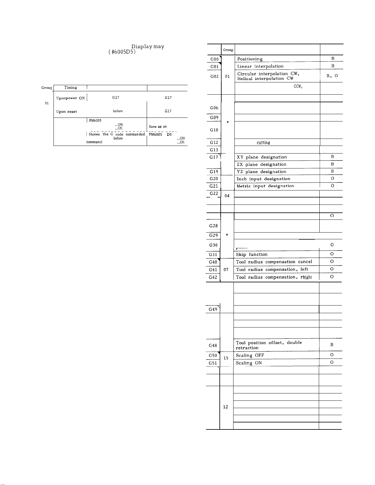
2.9.1 LIST OF G CODES AND GROUPS (Cent’d)
Table 2.18 List of G Codes
During the execution of G 92,
selectively be made. (#6005D5)
. G code in the 02 or 03 group at reset can be
set by parameters.
ON
Upon power ON
03
Upon reset , immediately
Parameter OFF
1- . . . . . . . . . . . . . . . -----
Stores the G code commanded
immediately
I
command
DO
o
. .
1
. .
this
this
may
I
------------
Parameter ON
the left
‘
. .
o
1
. .
G
code
G03
G04
G06
G09
Circular interpolation
Helical interpolation CCW
Dwell
Positioning in error detect
off mode
Exact stop
Function
Tool offset value and work
--
G1O
G12
G13
G18
G20 ,
coordinate, Shift-value
modification
Circle
CW
Circle cutting CCW
02
6
Stored stroke limit ON
G23
G25
G27
G28
G30
Stored stroke limit OFF
Program copy
*
Reference point check
Automatic return to
reference point
Return from reference point
Return to 2nd, 3rd, 4th reference
point
B: Basic
O: Optional
B, O
B
B
B
B, O
n
I
o
I
o
I
n
o
I
o
I
o
G43
G44 08
-1
G45
G 46
G 47
v
G52
G53
G54
G55
G56
G57
G58
G59
Tool radius compensation cancel
Tool radius compensation, left
Tool radius compensation,
1
Tool length compensation, plus
direction
Tool length compensation, minus
direction
Tool length compensation, cancel
Tool position offset, extension
Tool position offset, retraction
Tool position offset, double
*
extension
Return to base coordinate system
12
Temporary shift to machine coor-
*
dinate system
Shift to work coordinate system 1
Shift to work coordinate system 2
Shift to work coordinate system 3
Shift to work coordinate system 4
Shift to work coordinate system 5
Shift to work coordinate system
I
B
I
B
I
B
B
B
B
o
o
0
0
0
0
0
0
6
20
Page 29
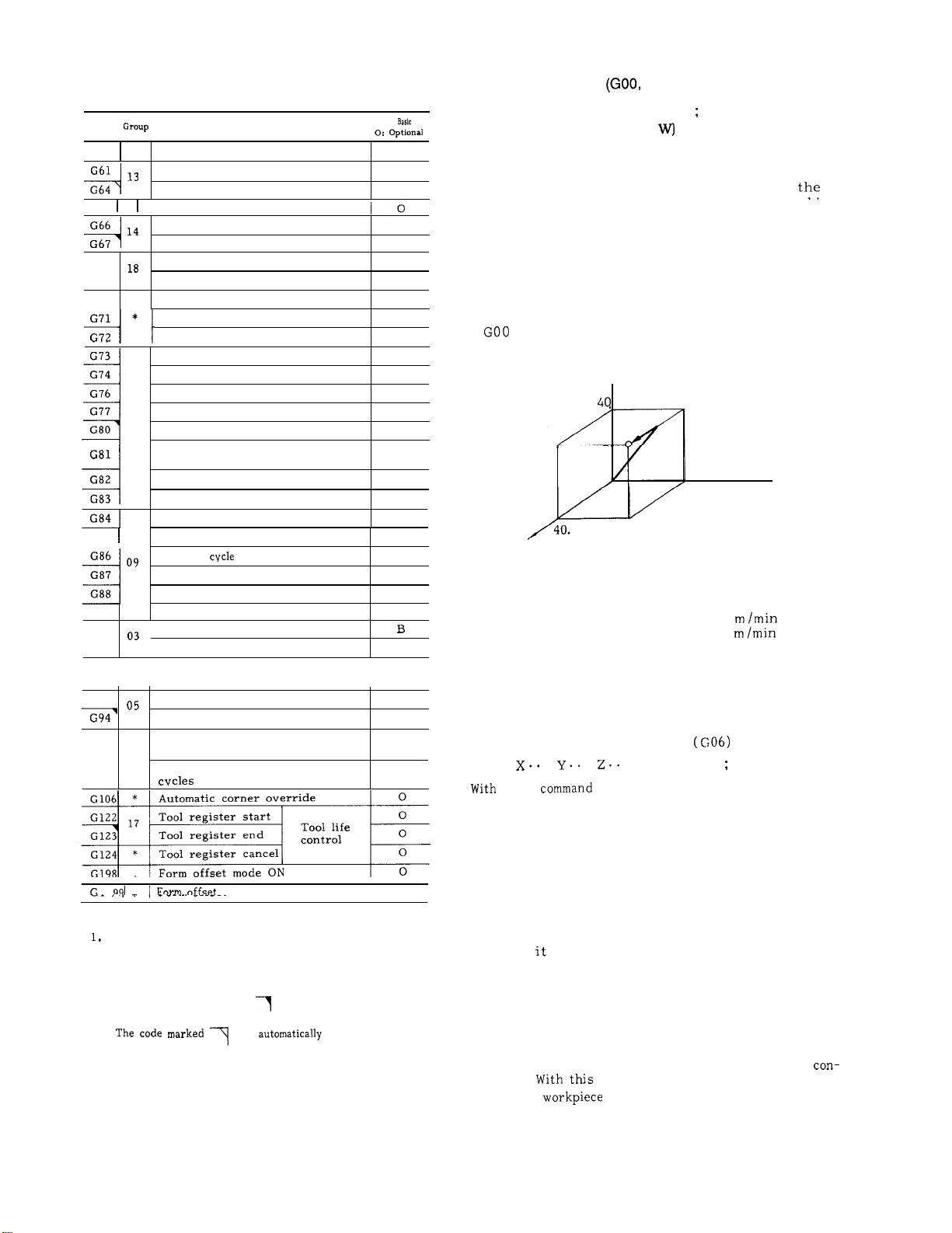
Table 2.18 List of G Codes (Cent’d)
G
code
G60
G61
G64
G65
G66
G68
G69
G70
G71 *
G73
G74
G76
G77
G80 09
G82
G83
G85
G86
G87
G88
G89
G90
G91
G92 *
G93
G98
G99
I
Function
Unidirectional approach
01
Exact stop mode
Exact stop mode cancel
*
Non-modal call of user macro
Modal call of user macro
Modal call of user macro cancel
Coordinate rotation ON
Coordinate rotation
Bolt hole circle
OFF
Arc
Line-at-angle
Canned cycle 10
Canned cycle 11
Canned cycle 12
Canned cycle 13
Canned cycle cancel
Canned cycle 1, Output
for external motion
Canned cycle 2
Canned cycle 3
Canned cycle 4
Canned cycle 5
Canned
6
Canned cycle 7
Canned cycle 8
Canned cycle 9
\
Absolute command designation
Incremental command designation
Programming of absolute zero
point
I
Solid tap mode ON
Solid tap mode OFF
\
Return to initial point for
canned cycles
10
Return to point R for canned
.
mode OFF
B ,
I
10
o
B
B
o
o
o
o
o
o
o
0
0
0
0
o
o
0
0
0
0
0
0
0
0
?3
B
o
o
o
o
Notes:
The G codes in the *
are effective only for the block in which they
are commanded.
twice or more in a block.
programmed only once in a block of its own.
The codes marked with
2.
selected at power on or reset.
3.
upon power ON.
group are non-modal, and
They cannot be programmed
They must be
are automatically
is
selected
2.9.2
POSITIONING
GOO
(where a = A, B, C, U, V, or WI
With this command, the tool is sent to the speci-
fied position in rapid traverse motions along the
3 axes ( 5 axes’) simultaneously. If anY Of
coordinate positions is not specified, the machine
does not move along that coordinate axis
The rapid traverse rate for the respective axes
are inherent to the machine tool.
machine tool builder’s manual.
EXAMPLE
GOO is a modal G code belonging to the 01 group.
X... Y... Z... (a
X40.
z
Y 40.
Error detect OFF
.
G06
this
.
, the same positioning motions
are initiated as with
following exceptions.
After the completion of the positioning motion
with G06 block, the program advances to the
next block in the ERROR DETECT OFF mode
(Note) . Therefore, the tool path at the corner
is rounded.
G06 is a non modal G code belonging to the *
group , and therefore, it is effective only in
which
Notes :
GOO commands position the tool in the ERROR
DETECT ON mode,
gram advances to the next block only after the
servo
is programmed.
lag pulses are decreased below the per-
missible level,
trol.
command, therefore the corner
of the
G06)
T
...)
Refer to the
Z40. ;
Y
o
40.
Rapid traverse rate
X
axis:
Y axis: 8
Z axis: 4 mimin
Fig. 2.11
positioning
(a t...)
.
a GOO command, with the
which means that the pro-
8 m /rein
x
and this is detected by the
is machined sharp .
21
Page 30
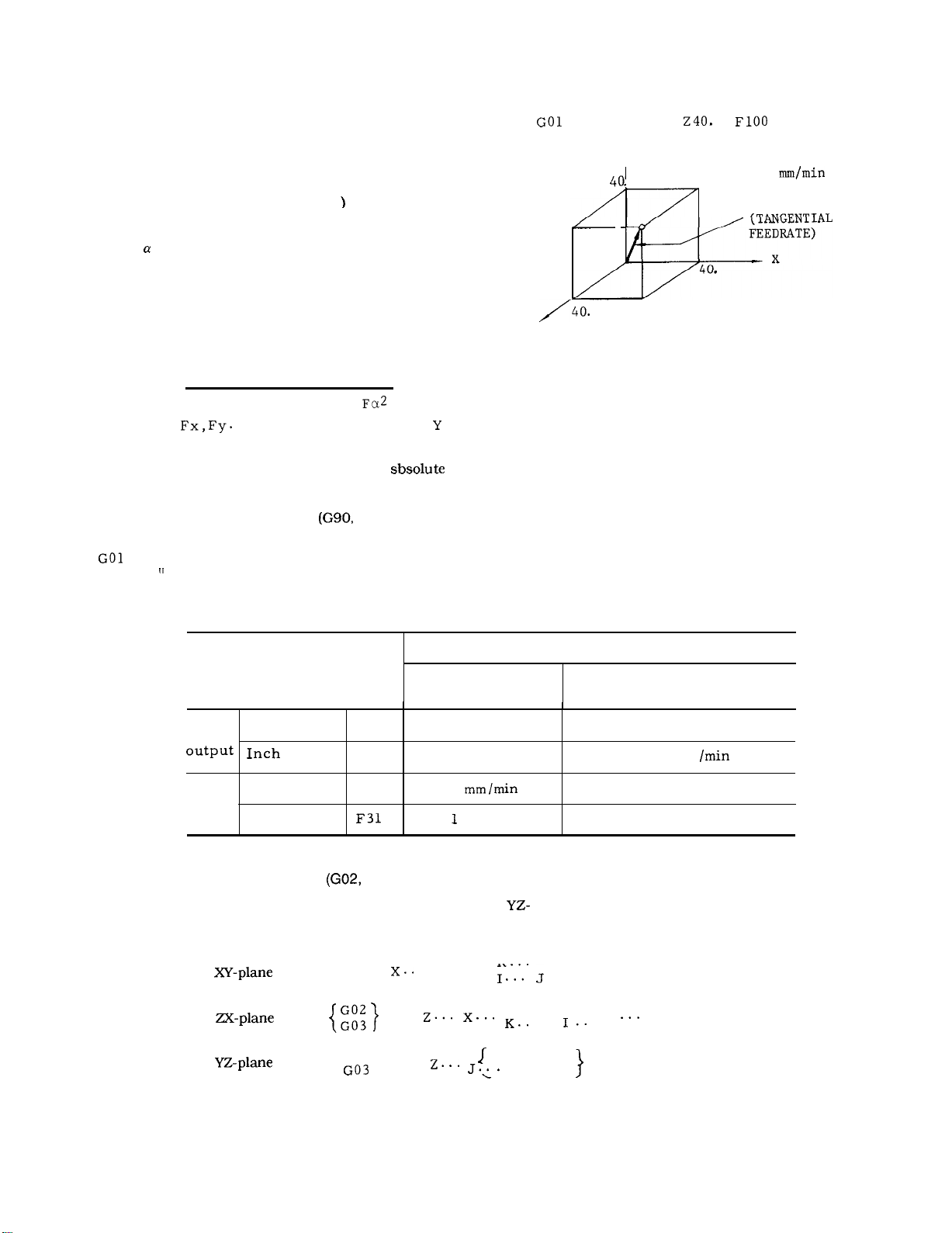
2.9.2
POSITIONING (GOO, G06) (Cent’d)
EXAMPLE
. With the ERROR DETECT OFF mode commanded
by G06, the program advances to the next block
immediately after the completion of pulse distribution.
LINEAR INTERPOLATION (GOI
2.9.3
GO1 X.. .Y. .. Z...
where
With this command, the tool is moved simultaneously in
the three (four t) axial directions resulting in a linear
motion. When a certain axis is missing in the command,
the tool does not move in the axial direction of that axis.
Feedrate is specified by an F code the feedrate in the
component axial directions are so controlled that the
resultant feedrate becomes the specified feedrate.
The end point can be programmed either in
coordinates or in incremental values with G90 or G91
respectively. (Refer to 2.9.30, “ABSOLUTE
/INCREMENTAL PROGRAMMING
If no F code is given in the block containing the
an error
= A, B, C, U, V, or W
F=
(where
directions. )
or in preceding blocks, the block constitutes
Fx2 + Fy2 + Fz2 +
030. “
(a t...)
are feedrate in the X ,
. .
F... ;
X40.
Y40.
Y
o
;
100
RESULTANT
FEEDRATE
z
Ftg. 2.12
Where the optional 4th axis is a rotary axis (A, B or C),
for the same F code, the feedrates in the basic three axis
directions (X, Y and Z), and the rotary axis feedrate are
as indicated.
Table 2.19 Minimum F Command Unit
F-function
Metric
Inch
output
Note:
CIRCULAR INTERPOLATION
2.9.4
With the following commands, the tool is controlled
along the specified circular pathes on the XV-, 2X-, or
Metric input
inp Ut
Metric input
Inch input
Feedrate of linear 4th axis as the same as that of basic three axes.
G 17
F50
F31 0.1 in. /rein
F50
G03)
G02
G03
{}
G02
G03
G02
{}
Feedrate of basic
. Y.. .
In minimum F command unit
three axes
1 mm /rein
1
in. /rein 1 deg/min
code.
R
. . . . . .
{
. . .
R
{
.
R.. .
K.. .
Feedrate of rotary axes
1 deg /rein
2.54 deg
O. 3937 deg /rein
F.. . ;
}
F
.
1
;
F... ;
22
Page 31

The moving direction of the tool along the circle
is as follows.
G02:
Clockwise
G03: Counter-clockwise
,
Fig. 2.13
When circular interpolation
programmed, usually, the plane of interpolation
should be specified in advance with G17, G18 or
G19.
EXAMPLE
G17 G90 G03 X15,
(a) Absolute command with
is to be
G17 :
G18 : ZX-plane or Z4-planet
G 19:
(when the 4th axis is linear)
In addition to the plane of circular interpolation,
these G codes specify planes for tool radius compensation
the contrary, XY plane (
matically immediately after the switching of the
power supply.
The end point of the circular arc may be specified
by G90 or G91 respectively in absolute or incremental values.
is always programmed in incremental values from
the start point, irrespective of G90 or G 91.
G17 G91 G03 X-40. Y20. 1-30. J-10.
(b) Incremental command
G42) .
However, the center of the circle
If no selection is made to
Y
END POINT
40.
20.
,
Instead of the coordinates 1, J, and K of the
center of the circle, the radius can be directly
specified with an R command.
circular interpolation with radius R designation
mode.
In this case,
when R
gle less than 180°, and
when R
gle larger than 180° are specified.
0, a circular arc with the center
0, a circular arc with the center
-
-30.
x
This is called
Fig. 2.14
G17 G02
Y
I
40
20
180° OR OVER
t-
I
15.
.
-R
-40.
55.
.
\
END POINT
\
x
;
180” OR BELOW
START POINT
Fig. 2.15
23
Page 32

2.9.4 CIRCULAR INTERPOLATION (G02, G03) (Cent’d)
G17 G02(G03) 1.. . J.. . F.. . Ln ;
With this command, complete circular interpolations
are repeated n times.
the interpolation is executed only once.
-plane
X
Z
-plane
Y
-plane
Without an L designation,
G17
G18
G19
G02
G03
{}
G02
G03
{}
G02
G03
Note :
. G17 G02
Where address characters for the 4th axis is
missing as in the above command, the
is automatically selected. Circular interpolation
cannot be performed on the axes including
rotary 4th axis.
Circular pathes covering two or more quadrants
can be programmed in a single block. A com-
plete closed circle can also be programmed.
EXAMPLE
XO YO ;
.
. . . . . .
. ;
}
G02 XO YO 110. JO F1OO ;
. . .
complete circle
Y
When a linear 4th axis option is used, circular
interpolation is possible in the X
planes in addition to the XY-, YX-, and
(where
.
1.. .
{
. . .
R
K.. .
.
.
{
= U, V, or W).
.
}
.
}
;
F
;
;
-, Z
The end point i
represented by
CENTER
*-
0
\
\\
Fig. 2.17
When the end point is programmed in the hatched areas shown above, no alarm state is created, but the tool will keep on rotating.
Especially when tool compensation is applied,
coordinate values of the point and the center
must be programmed accurately.
/
-, and Y
-
.s
~
.
10.
x
2.16
When the coordinate values of the end point of a circular
path is not exactly on the correct circular path due to
calculation errors, etc., correction is made as shown below.
Points O are commanded as end point. (See Fig. 2.17).
24
When radius is specified as O (I, J = O on G17 plane)
in
When
end point) at R command, the error is compensated for
in the range of
2.9.5 HELlCAL INTERPOLATION
A circular interpolation on a certain plane, and
a linear interpolation along an axis not included
in that plane can be executed in synchroniza-
tion, and this combined interpolation is called
helical interpolation.
circular arc, alarm 102 (CAL ERROR =
is triggered.
R (
: distance from the start point to the
– R
#6649.
G03)
t
Page 33

Command format
(a) For
(b) For
(c) For
(d) For X
(e) For Z.
(f) For Y
G19
G17
G19
G02
G03
G02
G03
{}
G02
G03
G02
G03
{}
G02
G03
{}
G02 y.. .
G03
.
10. .
{
. . .
R
.
{
.
.
{
{
{
R
. . . . . .
.
.
.
.
. . . . . .
K
.
.
Z(a) . . .
}
}
z
}
. . .
. . .
.
. ;
. F.. . ;
. F.. . ;
. ;
. ;
. ;
Where
w. If no 4th axis is programmed in (d) , (e) ,
and (f) , they are regarded as equal to (a) , (b)
and (c) .
EXAMPLE
z
90.
100.
2.18
Notes :
The circular arc should be within 360°.
As long as above note (a) is satisfied, the
start and end points can be taken at any time.
The feedrate F means the tangential speed on
the plane of circular interpolation.
Tool radius
only to the circular path on the plane” of
c
interpolation.
DWELL (G04)
2.9.6
G04
This command interrupts feed for the length of
time designated by the address P .
Dwell is programmed as an independent block.
The maximum length of time which can be desig-
nated with address P is as follows.
;
END POINT
C
can be applied
Y
;
Format Dwell time (P programmable range)
P53
The value does not depend on metric
or metric /inch output.
EXAMPLE
G04 P2500 ;
Dwell time: 2.5 sec.
Two types of dwell can be selected by parameter:
Dwell when the specified value in the command
block before the dwell block is identified by lag
pulses of servo, or dwell on completion of pulse
distribution.
2.9.7
Exact stop
When a block containing G09 is executed, the
program advances to the next block after com-
pleting a block in the Error Detect On mode
(Note a) .
corners are desired.
effective only in the block in which it is contained.
Exact stop mode
When once G61 is commanded, all the following
blocks will be completed in the Error Detect
On mode before proceeding to the next block.
Exact stop mode cancel ( G64)
This G command is for canceling the effect of
G61.
0 - 99999.999 sec
EXACT STOP
This function is used when sharp
rnput
G61 , G64)
G09 is non-modal, and is
25
Page 34

2.9.7 EXACT STOP
Notes :
. In the Error Detect On mode, the program pro-
ceeds to the next block only after the number
of servo delay pulses is found to have decreased below a permissible limit following the complete distribution of circular interpolation
command pulses.
In the G09 and G61. off modes, the program pro-
ceeds to the next block immediately after the
complete distribution of the pulses of ordinary
linear and circular interpolations, and there-
fore, because of the servo delay, tool pathes
are rounded at the corner. This mode is called
Detect
G61, G64) (Cent’d)
‘ode”
(b) For the work coordinate system setting B
specification, change the setting of the work
coordinate system by
Y.. . z.. .
meaning of
(a).)
2.9.9 CIRCLE CUTTING
This is a canned cycle which includes a complete
series of movements for machining a circle in a
single block.
. Format
It includes the following functions.
.
.
G 10 Q2 Pm Jn X . . .
(Jn specifies J1 to J5. The
G13)i
. ;
. For rapid traverse,
Off modes are controlled only by GOO and
and not by the above G codes.
the Error Detect On and
G06,
2.9.8 TOOL OFFSET VALUE DESIGNATION (G1O)
With a G1O command, correction of tool offset
values and work coordinate system can be made
as follows.
(1) Designation of tool offset value ( G1O)
Normally, tool offset values are written in by
MDI .
and R = tool offset value) , any programmed
offset values can be replaced by a designated
value.
When G1O is commanded in the G90 mode, R is
stored as it is.
When G1O is commanded in the G91
added in the previous tool offset value.
(’2)
(a) Corresponding to G54 through G59,
work coordinate systems are set up
data in advance.
On the other hand, with a program G1O
.
. ; , (where P = tool offset number
mode. R is
coordinate
separate
as setting
Y
Fig. 2.19
Designation of rapid traverse section R
.
With this command , a circular bore is machined
as shown below.
character R specifies rapid traverse sections.
.
Numerals following an address
I
.
;
G1O
(where
offset value designation and a means to set up
a work coordinate system.
corresponds to the work coordinate system m
to be set up. )
For
For
For
With the above command, data of any desired
work coordinate system can be changed.
is used to discriminate from tool
G54
. .
G59 corresponds.
Fig. 2.20
Page 35

Commanding repeated circle designation
.
With this command, the circular bore surface
can be executed L times.
Commanding spiral circle Q, K
.
With this command, the tool is moved along a
spiral before finally finishing a circular hole,
as shown below. For the sake of simplification,
the diagram shows the tool path with a zero
radius (D = O) .
programmed without sign.
Tool path
(D) represents a set value of tool radius
compensation.
Clockwise
Counterclockwise
Radius of finished circle
I:
(incremental value with sign)
Rapid traverse section
R:
(incremental value with sign)
.
.
. ;
.
.
Q (radius increment) must be
.
. ;
Combined designation
tion, repeated circle and spiral circle.
Rapid traverse section, repeated circle designation and spiral circle can be commanded in
combination as shown below.
I.. .D. .. R...
.
Notes :
Circle cutting is possible only on the XY plane.
The tool speed in the rapid traverse section is
set by parameter #6225.
Feedrate override cannot be applied to rapid
traverse rate.
tool speed conforms to dry run speed.
With a circle cutting command
tool is offset for its radius compensation with-
out the use of G41 or G42 (tool radius compen-
sation) .
radius compensation with G40.
In the explanation above, only motions in the +
direction of X-axis is considered. With proper use of
signs for I, K and D codes, motions in the - direction
of X-axis (symmetrical with respect to Y-axis) can be
commanded. In Fig. 2.23, signs of I, R and (D) are
minus. However, cutting in the Y-axis direction
impossible.
I, J, K, R, Q and L codes in circle cutting command are effective only in the block containing
them.
When using
While dry run switch is ON, the
rapid traverse sec-
K...
Tool radius compensation No.
D:
Cutting feed rate
F:
Y
G12:
I
Fig.
Y
RADIUS
INCREMENT
x
RADIUS OF
FINISHED CIRCLE
Fig. 2.22
27
Page 36

2.9.9 CIRCLE CUTTING (G I 2, GI 3) t (Cent’d)
Tool path
5
I
F
CUT
G13:
(D) represents a set value of tool radius
compensation.
. The radius I of finished circle and the rapid
traverse section R are subject to the following
restriction.
with the restriction are programmed , this is
regarded as an error.
E XAMPLE
.
Z-40. ;
G12 150. R40. D1O F300 ; D1O
5
When values not in conformity
❑ 10.
Z40.
RAPID
50
Fig. 2.24
When G12 or G13
conditions must be satisfied :
Condition 1 : D
Condition:
Unless otherwise, section R is
machine moves at F-feed speed.
2.9.10 PLANE DESIGNATION
J
UTED
SECTION
invalidated and the
G18, G19)
(a)
GOO Z- 40. ;
G13 I-50.
GOO Z40. ;
. .
Fig. 2.23
D15 F300; D15 = -8.0 mrn
The plane for making circular interpolation and
tool radius compensation is designated try G codes
When the 4th
the following planes are newly added.
G17 :
G 18:
G 19:
The move command in each axis can be programmed regardless of the plane designation by
For example, if
G17 Z.. . ;
is designated, motion is on Z-axis.
of linear axis is s-elected,
28
Page 37

The plane for making tool radius compensation by
command G41 or G42 is
G17, G18 or G19. It is not possible to designate
compensation plane including
axis.
The
turned on.
(G 17) is selected when the power is
4th axis of rotary
Take the following procedure after the command
of G20
Program absolute zero point
A.
before move command.
In principle, make the display reset opera-
B.
tion when current position display ( external) is used.
selection.
2.9.11
DESIGNATION BY G CODE
(G20,
Unit of input data are selectively specified by the
following G codes between metric and inch.
Metric
These G codes are programmed at the leading end
of a block of its own. If one of these G codes are
commanded, the units of all the following motions
are changed afterwards.
subsequent programs
. tool offset values
. part of setting parameters
. part of manual movements
displays
Notes :
When G20 or
inch/metric selection is changed. Therefore,
the state of
is commanded, the setting of
on the setting by parameter
The tool offset values are processed differently in the G20 mode and the
the tool offset values.
mode.
2.9.12 STORED STROKE LIMIT (G22, G23)
function is for checking the current tool
position during manual or automatic operation
for entry into the prohibited area specified by
parameters or by G22.
hibited area, machine operation is stopped and
an. error sign is displayed.
. 1st prohibited area (stored stroke limit 1)
The area outside the area specified by a parameter is a prohibited area.
be used as a substitute of overtravel checking
function. Upper limit point A
point B
are specified by parameters.
If the tool enters a pro-
Generally, this can
and lower limit
Ya, Za)
EXAMPLE
ER
CR
01234 ;
;
. When
program, take the following procedure before-
hand.
A. When work coordinate system ( G54 to G59)
is used,
tern.
B . Cancel all tool compensation command.
(G41 to G48)
return it to base coordinate
Inch input designation
/“
///////’
Yb, Zb) ‘
/
/’
z
x
Fig. 2.25
29
Page 38

2.9.12 STORED STROKE LIMIT (G22, G23)
2nd prohibited area (Stored stroke limit 2)
The boundary of the 2nd prohibited area is
specified by a parameter setting or by G22.
The inside or the outside of the boundary
selectively be made a prohibited area by means
of parameter setting.
G22
C point
Upper limit
D point
Lower limit
(Cent’d)
KC.
;
2ND PROHIBITED AREA
/
/
/
///
(I, J, K)
Where 2nd prohibited
area is outside.
Az(x, Y, Z)
/’/
With this command, the checking of the 2nd
prohibited area is started, and with G23 ;,
the check function is cleared.
Table 2.20 Setting of Stored Stroke Limit for Each Axis
ited area
2nd
ited area
Point
Point
point A2
Point B 2
#6600
#6606
#6510
#6513 #6514
Y, Z)
Where 2nd prohibited
area is inside.
Fig. 2.26
x
Y
#6601
#6607
#6511
z
#6602
#6608
#6512
#6515
Division
Parameter
Setting
Note: Point A sets plus value of boundary line on the machine
coordinate
The parameters for specifying the inside and
the outside of the 2nd prohibited area are as
follows .
#6007D0
“
o“
1!
Meaning
Inside prohibition
outside prohibition
30
The 2nd prohibited area checking function can
also be turned on and off with the following
setting number.
Meaning
Page 39

Notes :
The
specified overlapping each other.
Boundary lines on the minus side are included
in the prohibited areas. Boundary
the plus side are not included in the prohi-
bited areas.
All the prohibited areas become effective after
a manual return to reference point or a return
to reference point by
the power supply.
If the tool is in the prohibited area at the time
when the prohibited area becomes effective,
this is immediately regarded as an error. In
this case, turn off the 2nd prohibited area by
the setting of the setting number, and either
rewrite the data or move the tool out of the
prohibited area manually,
If an alarm state is created by the entry of the
tool into the prohibited area, the tool can move
only in the returning direction.
The stored stroke limit cannot be checked dur-
ing a machine lock operation.
PROGRAM COPYt (G25)
2.9.13
(1)
The command G25P
. . . . . .
sequence
program
G25: Program copy G code
P:
Q:
Each will be commanded with four digits. The leading
zeros of p2 and q2 cannot be omitted.
L: Number of repetitions (One time if omitted)
(Z) Although the
tape, MDI or memory operation, it will be necessary to store the program to be copied in the
memory, When sequence numbers are overlapped,
the first sequence number will become effective.
(3) The G25 command may also be used again
in the program being copied. This is called
multiple program copying and is possible up
to a maximum of four levels. However, error
“ 042” will occur if four levels are exceeded.
executes L times any program from
First O number
p2; First sequence number (N)
Last O
q2; Last sequence
command can be given by
Q
on
L
(4) Program copying can be commanded in a fixed
cycle (G70 to G72,
(5) Simple jump command “M99” can be used in
the program being copied by the
It is the same as the M99 function commanded
in the main program.
Notes :
(a) Error “042” will occur if
of levels called by G25 and
when used in a subprogram.
(b) If G25 is used during
(G65, G66), Up to four separate
(c) Since the sequence number specified by address
p2 and q2 will be searched from the first number
of each program, care will be required not to
duplicate the sequence numbers. If duplicated,
the first sequence number will become effective.
(d) In command G25 P (pi) (p2)
following errors will occur.
Error “070 when p 1 cannot be searched
Error “04 1” when p2 cannot be searched
Error “040 when p 1 and q 1 are not the same
(e) If a reset operation for errors or an M30/M02 reset
occurs when executing command G25, execution will
return to the beginning of the called program of the O
level.
(f) If a P or Q command is less than four digits,
it
the program sequence number will be searched.
(g) The leading zeros in both commnads P and
Q can be omitted. However, for five digits or
more,
the sequence number.
(h) If M98 or M99 is commanded in the G25 block,
error
(i) Since M99 will have priority if it is in the
block (End block of G25) specified by q2 of
G25, the command will return to the beginning
of the program being executed. Do not command
M99 in the block specified by
omitted. When omitted, it will automatically be
considered to be the same as the leading O of the P
command.
(k) A program copy command in a fixed cycle
cannot be commanded in the
fixed cycle command. If commanded, G code
the lower four digits will be considered
will occur.
The O
at the end of the
will occur.
G73, G76,
to
the total number
M98 exceeds four
a user macro call
are possible.
(q2) L . . .
command can be
same block with the
the
(1) When the block indicated by G25 q2 (end block of
G25) is a G25 block, q2 is disregarded and the next block
3rd
is proceeded.
Therefore, create a program as shown page 32 and 33.
31
Page 40

2.9.13 PROGRAM COPY t (G25) (Cent’d)
Example
G25 P7 Q8 Ll;
G73 Z-1, R-2. Q1. F1OO;
N3 G80;
N4 GO X1 O.;
N7 G25 P2 Q4 L9;
N8 G25 P2 Q3;
N 9 G90 X-90. Y-10.;
AFTER MODIFICATION
N7 G25 P2 Q4 L9;
G25 P2 Q3;
N8;
N 9 G90 X-90. Y-10. ;
ApE0RMEM0Ry
‘
00001;
N1O
P1OO
I
(Note)
I
1
O Level
Program No. 00001 Program No. 00001
7r
MEM0Ry
N1OO-----------;
I
1
P200
I
1
1st Level
Note: Always use the program number in the P
command when commanding from a tape.
Example: N1OG25
Reset operation
calls the beginning
of the memory.
---
1
1
220
I
RESET
Program No. 000001
Q1550; Programl number
P400;
2nd Level
I
I
I
/
I
1
I
I
I
I
I
I
N380 M99;
3rd
Program No. 00400
Level
32
Page 41

NOO1
I
NOl O
QO1O15O:
PO1O1OO
N1OO
I
I
G25 POO11O2OO
QOO11O25O:
I
I
N200
N225
N300
I
I
I
I
I
I
P65;
I
I
I
I
I
O Level.
Program No. 0050
Notes :
1. M98 can be used in a program
G25. Four levels may
when using G25 with M98.
2. Care should be taken when jumping to a
different L level with M99 since execution will
become endless with no means of escape.
2.9.14 REFERENCE POINT CHECK
This function is for checking the correct return
of the tool to the reference point after performing
a cycle of operation in accordance with a program
which starts at the reference point and ends at
the reference point.
.
.
G27
With this command, the tool moves towards the
specified position
simultaneously but independently, and after the
arrival at the specified point, the point is checked for the conformity to the reference point. If
any of the axes is omitted in the command, the
tool does not move in that axis and no check is
made in that axis.
If the point is in conformity with the reference
point, the reference point return lamp lights.
If the tool is correctly in the reference point in
all the axes, automatic operation is performed
further, but if the tool is not in the reference
point even in one axis, this is regarded as an
error ( alarm 241 - 244 display) , and the automatic operation is interrupted. (Cycle start
lamp goes off. )
If G27 is commanded in the tool offset mode, the
tool return point is also offset. Cancel the tool
offset mode when commanding G27.
.
the three axes ( 4
I
1st Level
Program No. 0001
I
N400
3rd
“99;
Level
N250
2nd Level
Program No. 0011 program No. 0065
copied with
exceeded even
Reference point as meant here is a freed point relative to
the machine to which the tool returns by the manual
reference point return motion or by G28 automatic
reference point return motion. Refer to 5.2.1,
RETURN TO REFERENCE POINT’ on page 174. The
mirror image function can be applied to the G27
command. To avoid non-conformity errors, clear the
mirror image mode with M94 (Mirror image
commanding G27.
AUTOMATIC RETURN TO REFERENCE POINT
2.9.15
t
G28
With this command, the tool is sent back to the reference
point. The tool moves towards the specified points in
rapid traverse, and automatically stops at the reference
point.
However, the tool will not move in the direction of the
axis for which a coordinate instruction is omitted.
axes (4 axes
).
Page 42

2.9.15 AUTOMATIC RETURN TO REFERENCE POINT
(G28)
(Cent’d)
EXAMPLE
.
.
G28
—-
I
“Return to reference point” involves the same
series of motions as the manual return to
ence point.
Notes :
If G28 is commanded in the tool radius compen-
sation mode
this is regarded as an input error “ 024.
If G28 is commanded in the Mirror Image mode
, this constitutes an input error “058. “
The tool position offset command is not
G28. Be sure to cancel it before commanding G28. If
G28 is given in the tool position offset mode, the tool
motion by the succeeding program becomes as
described below. Care should be taken.
When the succeeding program is made in the
A.
incremental mode:
Tool moves by the amount of incremental
value from the reference point .
offset is not effective.
B.
When the succeeding program is made in the
absolute mode:
Tool moves to the position which is specified by absolute value and tool offset value.
When G29 is given immediately after the
G28:
By G29 command, the tool moves to the offset interim positioning point and the suc-
ceeding motion is made according to the
item A and B.
When returning the tool to the reference point for the
first time after turning on the power supply. pay
attention to the tool position.
TO REFERENCE
. ;
I
,
Y-AXIS DECELERATION LS
2.27
G42) or in a canned cycle,
REFERENCE POINT
c
- — DECELERATION
.
Z-AXIS
Y
The tool
Return to reference point in rapid traverse
In addition to the above “ Automatic Return to
Reference Point, “ “ Rapid Traverse Return to
Reference Point” function may be incorporated in
the control.
quence is as follows.
After positioning at an interim positioning point
B , the tool directly moves to the reference
point in rapid traverse. The returning time is
shorter than that with the ordinary return to
reference in which deceleration LSS are used in
all the axes.
Point, ”
the reference point return possible area.
The rapid traverse return to reference point
becomes possible only after the tool has been
returned once to the reference point in all the
axes by manual operation or by G28, following
the turning on of the power supply.
Rapid traverse return to reference point is effective only with G28.
are not changed by it.
Where a
for the 4th axis in a G28 command, and when the tool
has been returned to the reference point in the X-, Y- ,
and Z-axis, the tool moves to the reference point in the
rapid traverse return mode. If
axis is included in the command, the tool returns to
the reference point in the ordinary return mode,
completed.
For return to reference point in rapid traverse, tool
cannot be moved in RAPID or JOG mode unless
REFERENCE POINT RETURN switch turns off after
completion of reference point return.
2.9.16 RETURN FROM REFERENCE POINT
This code is used to return the tool to its original
position after return to reference point by automatic
return to reference point
G28
G29
With this function, the motion se-
e
point B may not necessarily be within
Return
Manual return motions
Reference
4th axis is used, when no command is given
a command for the 4th
. Z.. . ;
Point B
.
v
. ;
/
(Reference point)
Point D
c
(REFERENCE POINT)
B
(INTERIM POSITIONING
POINT )
REFERENCE
POINT
34
A
Fig. 2.28
Page 43

When G29 is programmed, it is not necessary to
consider the distance between point B and C in the
program. Particularly when an incremental command
is used, this is effective for returning tool to the
original position, after returning to reference zero.
Movement of C
traverse rate simultaneously along three axes
(simultaneously four axes t) by G29. However, in an
axis for which a coordinate command was omitted,
the tool will not move.
If G28 is programmed a number of times, the
creates is effective for the move of G29.
B and of B
D is made at rapid
An input error
without execution of G28 after the control is
turned on.
In principle, cancel tool offset before programming G28 or G29.
offset is also effective. interim positioning
point B will also be offset, and the tool passes
point B’ .
If they are programmed when
if GZ9 is given
c
-
(REFERENCE POINT)
EXAMPLE 1 (In the case of absolute input)
Interim point
N21 G90 ;
N22 G28 Z1O.
N23 G28 X30. ;
blocks
EXAMPLE 2
N31
N32 G28
N33 G28 X20.
N34 M06 ;
N35 G29 X40.
;
Y20.
.
Y40.
Y-40.
coordinates
XY
(o, 20.
( 30.
, 10. )
c
(REFERENCE POINT)
z
, 10
.
OFFSET
----/
)
0
An input error “058” occurs if G29 is given during mirror image
The
be taken
G28 does not meet with that of G29.
(1) The following operations are made between
(2) G28 and G29 are commanded in the blocks
(3) G28 and G29 are commanded after manual
A’
command or operation must not
G28 and G29 commands.
Setup of coordinate system (G92, ORG key)
. Machine lock
Manual operation at Manual Absolute Off
following the block containing M94 which
cancels mirror image at the different point
from the starting point of mirror image.
operation at Manual Absolute Off.
B
(INTERIM POSITIONING
POINT)
Fig. 2.30
interim positioning point B of
/
40
Fig. 2.29
Notes :
. An input error
med in tool ‘radius compensation mode ( G41,
G42) or during canned cycle mode
G76, G77, G81
if G29 is program-
G74.
2.9.17 RETURN TO 2ND, 3RD AND 4TH REFERENCE
POINT
G30 Pn
(where Pn = P2, p3, p4)
With this command, the tool first moves to an interim positioning point, and then, moves to the
2nd, 3rd or 4th reference point.
P2:
P3: 3rd reference point
P4:
If any axis of the coordinate instruction is omitted,
the tool remains motionless in the direction of that
axis.
Each reference point is specified by the
eters (#6612 to #6629) before hand.
t
.
.
.
2nd reference point
(a t...) ;
When P is omitted,
the tool moves to
the 2nd reference
}
point.
35
Page 44

2.9.17 RETURN TO 2ND, 3RD AND 4TH REFERENCE
POINT (G30)
EXAMPLE
G30 P2 x30. Y50. : The tool returns to the 2nd
(Cent’d)
reference point moving in
the X and Y directions.
When G29 is commanded after G30, the tool
moves to the designated point
of interim positioning point designated by G 30.
However the interim positioning point is renewed on the axis designated by G 30.
SKIP FUNCTION (G31)t
2.9.18
G31
. Y.. . Z.. .
(a t...) F...
G29 by way
VALUE
I
‘-—
CURRENT
– -
= a,
(30. ,50.)
INTERIM
POINT
H
o
2
ND
REFERENCE
POINT
Oz
G92 COORDINATE SYSTEM
(o, o)
(a) First, positioning
30. Y= 50.). The interim point
of the G92 coordinate system or work coordinate
system (G54 to
(b) Then positioning is executed at the second
reference point as follows :
2nd reference point position
= X-axis machine reference point + (#6612)
Y-axis 2nd reference point position
= Y-axis machine reference point + (#6613)
In the above example, when ;
X-axis machine reference point = O,
Y-axis machine reference point = O,
#6612 = 10.000 and
#661 3 = 20.000 in the G92 coordinate system, the
machine moves to the following positions by rapid
traverse.
X-axis 2nd reference point position
= X-axis machine reference point + (#6612)
= o + 10.000 = 10.000
Y-axis 2nd reference point position
= Y-axis machine reference point + (#6613)
=
o +
20.000 = 20.000
(c) Output during stay in the 2nd reference point
(#12014, #12015) is provided in the range of 3 micron
Znd reference point.
Notes :
Three items except the last one in NOTES of 2.9.15
AUTOMATIC RETURN TO REFERENCE POINT
on page 33, apply to G30 in the same manner.
2ND REFERENCE POINT
SHIFT AMOUNT
coordinate value
y=b)
With this command, a special linear interpolation
is commanded.
under the command of this program, whenever a
skip signal is inputted, the interpolation is inter-
rupted immediately, and the program advances
to the next block.
signal is inputted to the time the control start
to process the signal, delay time is less than
0.5m sec. G31 is non-modal.
EXAMPLE
N1OO G90 G31 X1OO. Y50.
N200 GO1 x80.
SKIP SIGNAL
During the interpolation movement
From the moment that a skip
;
IS
INPUT HERE
5a)
Fig. 2.31
When
being inputted, the machine stops at the end of
the block, and the alarm code “087” is displayed.
Feedrate of the tool is set for G 31 blocks selec-
tively by one of the following two methods as
specified by parameter
To be specified by F similar to ordinary pro-
grams.
To be set in advance by parameter #6232.
When a skip signal is inputted, the coordinate
values at the moment are automatically stored as
parameter data.
storing X coordinate value
#6552
#6553
#6554 . . .
#6555 . . .
. .
storing Y coordinate value
storing Z coordinate value
storing 4th coordinate value
36
Page 45

These coordinate values indicate the positions
when skip signal is ON and not the position when
the tool is stopped.
These data can be treated as coordinate data in
user macros.
When a skip signal is not given in spite the execution of G31 by setting ( #6004DO) , the program
moves on to the next block automatically.
Note :
near the skip final reference point, the dead zone
exists in the skip signal processing in the range
shown below. At this time, alarm “87 occurs when
#6004
value of the commanded axis is stored in #6552 to
#6555.
When actual skip stop detecting position is
*
SKIP SIGNAL IS
INPUT HERE
N
A-
I
C
(100.,50. )
ACTUAL MOTION
PATH
(80.,15. )
Table 2.21 G codes of Tool Radius
Compensation C
G code
G40
G41
G42
Note:
Group
07
07
07
When the power is turned on, G40 is
effective.
Cancellation of tool radius
compensation C
Tool radius compensation
C , left
Tool radius compensation
C , right
Meaning
Note that the directions of compensation
(right, left) indicated above are reversed
when the sign of the tool radius value in the
offset memory designated by a
ative.
the block containing G41, G42 or in a preceding block.
will be regarded as “O.
Make sure to designate a D code in
If DOO is commanded, tool radius
(LEFT)
D code is neg-
(Metric input)
7500 60 XKP
(Inch input)
7500 60 XKP
F: Reference speed (metric input : mm/min,
inch input : inch/rein)
2.9.19 TOOL RADIUS COMPENSATION C
(G40, G41 , G42)
It is possible to specify the radius of the tool and
to cause automatic tool path offset by this value.
Store the offset value (tool radius value) in the
offset value memory in advance by MDI, and program the tool offset number correspond to the
tool radius value by a D code in the program.
1.
Designation of compensation direction and
of D code
Tool radius compensation C is programmed
with G41, G42 and is
G41 and G42 indicate the directions of tool
offset with respect to the direction of movement.
t
2
+
1000X60
2
+
1000X60
by G40.
)
1
TOOL
PROGRAMMING
Switching between G41 and G42 can be made in
compensation mode. Details will be given in item 5
on page 40.
2.
Designation of compensating plane
The plane in which tool radius compensation is made
is designated by G17, G18, G19.
They are G codes of 02 group. The
in effect at the time power is turned on.
Table 2.22 G Codes for Designation
G code
G17
G18
Group
Fig. 2.32
of Planes
02
02
D
(RI
GHT
)
I
Meaning
02
Note: When the power is turned on, G17
is effective.
37
Page 46

2.9.19 TOOL RADIUS COMPENSATION C
(G40, G41, G42)
Make sure to designate a G code for plane
designation in the same block as that of G41,
G42 or in a preceding block. Plane desig-
It is not possible to apply tool radius compen-
sation in a plane including the 4th
3.
Method of entry into compensation mode
(Cent’d)
EXAMPLE B
(C) G17 GO1
. . . . . .
x Y
G02
TOOL , G40
. ;
. ;
.
.
. ;
\
When
to an offset position with the distance equal
to the radius.
normal line at the start point of the block
immediately after G41( G42) . If no coordinate
instruction is programmed in the block of
value only.
a movement, it is necessary to program GOO
or GO1 for a G code in group A. An input
error (alarm code “026) occurs if a G code
other than GOO, GO1 is programmed.
EXAMPLE A
(a) G17 GO1 F.. . ;
is programmed, the tool moves
The offset position is on the
, movement is made by the offset
Because
. X.. .
. ;
/ TOOL,
‘\
-
\
. ;
----
(d) G17 GO1 F.. . ;
. ;
G02
TOOL , G4
. Y.. .
CENTER
b
CENTER
- . .
-.
G42
. ;
y
G41
\
\
(b) G17 GO1 F.. . ;
G02
38
.
.
, TOOL, G40
Fig. 2.33
PROGRAMMED
.
.
. ;
CENTER
;
PATH
Fig. 2.34
Pay attention to the fact that offset is made
on the normal line to the program line
mined by the block after
start point in all of the examples (a) to (d)
above.
sation plane is not programmed in the block
after
ahead and the compensation start with the
block .
can be programmed continuously up to two.
Input error occurs if move commands on the
compensation plane are not programmed in
more than three blocks .
When compensation entry is programmed in
the GOO mode, positioning movement is made
independently
point.
fere with the workpiece.
When the movement on the compen-
, the next one block is read
The blocks without move command
each axis to the offset
Take care not to make the tool inter-
at the
Page 47

4.
Movement in compensation mode
When after the tool radius compensation is
programmed by G41, G42, the tool moves along
the offset path until the instruction G40 is
given.
As talc
made by the control, designate only the
shape of the
tool path is controlled as follows depending
on the angle between blocks.
A. Inside corner ( 180° or less) :
Intersection computing type
Fig. 2.35
B. Outside corner (over 180°) :
Circular path type (in the case of M96)
in the program. The
M96 . . . Tool radius compensation circular
path ON
M97 . . .
Normally, M96 is used for this operation,
however,
M96, M97 should be used.
c. Movement in GOO mode
The instruction GOO positions tools independently along each axis toward the final offset
position.
path.
Tool radius compensation circular
path OFF (execution of intersection
computation)
when there is a possibility of an
in cutting special shapes with the
Care should be taken on the cutter
G
OO
OR
GO1
Fig. 2.36
In this case,
included in the former block.
Code M97 can be used to machine the outside corner by the intersection computation, depending on
the work. For details, refer to 2.8.6, “CIRCULAR
PATH MODE ON/OFF ON TOOL RADIUS COMPENSATION C
movement of circular path is
/
(In
00
M96 mode)
Fig. 2.37
GO1
OR
39
Page 48

2.9.19 TOOL RADIUS COMPENSATION C
(G40, G41, G42)
Shape requiring care
D.
(Cent’d)
Do not program a wedge shape having an
accute angle.
G42
---
--
/
_ — -----------
The intersection is
located at a far point
Increase
the angle
Command involving no movement in compen-
5.
sation mode
The control normally reads in advance two
blocks during tool radius compensation mode
and computes the tool path.
these blocks give no coordinate instructions
such as
block further ahead and makes computing.
If either of
---
r
---
--__ ------
-------
.
G42 ,
I
2.38
I
(a) Wrong
Where the tool cannot
enter the wedge shape,
the intersection
is located on the opposite
side.
G41
(b) Correct
Program a
-1
The blocks withno coordinate instructions
can be processed continuously up to two
blocks .
missing in three or more blocks, tool radius
compensation becomes impossible and accurate
tool path cannot be
a Program where G41 or G42 is used, ensure
that, after them, three or more blocks without
movement command plane will not follow.
the entry
When coordinate instructions are
path allowing
of the tool.
40
Page 49

EXAMPLE
G17
.
x.. . Y.. . ;
. ;
. Y.. . D.. . F.. . ;
G04 P1OOO ;
. . .
x Y.. . ;
.
. . .
z
. . .
z
. . . . . .
x
G40
If no move command is programmed in three continuous
blocks, offset in the block immediate before them is made
on the normal line at the end point. Where movement
the compensation plane cannot be programmed in three or
EXAMPLE
NOO1 G17 GO1
NO02
Y
. ;
.
. ;
T
. ;
. Y.. . ;
. Y.. .
Blocks without movement
in compensation plane.
(When these blocks are within
two, machining is made smoothly. )
. F.. . ;
more continuous blocks for retracting in the third axis or
the like, and offsetting on the normal line is not
ry, a dummy block can be inserted by I, J or K.
NO1O X.. . Y.. . ;
N012 Z.. . ;
N019 Z.. . ;
N029
N030 G40
-——
. Y.. . ;
. Y.. . ;
1
1
Z axis
Dummy block
I
Y
J
I
I
Fig. 2.39
020
(x,
.
41
Page 50

2.9.19 TOOL RADIUS COMPENSATION C
(G40, G41, G42)
The dummy block is not programmed for actual move-
ment but it only provides data required for tool radius
compensation computation. In the example indicated
above, an instruction that is the same as the first block
of restarted movement of the
movement of Z axis is programmed as a dummy by I and
J. I, J and K are used as the addresses of this dummy
instruction, and they correspond to X-, Y-, Z-axis
respectively. Suitably use them in accordance
plane designation.
EXAMPLE
N050 GO1
(Cent’d)
.
after
the
. ;
I:
Dummy for X-axis
command
Dummy for Y-axis
J:
command
programmed in
incremental
values
K: Dummy for Z-axis
command
If X... Y.. .
the above example, give an instruction by converting into incremental values.
Note: Make a dummy block as follows if the
object of the dummy block is circular
interpolation.
of N020 is in absolute values in
N051 GO1 I(b)
N052
N053 2.. . ;
N059 Z.. . ;
N060 G03 X.. . Y.. . I(a) J(b) ; — Circular
N061 GO1 X.. . Y.. . ;
is, insert a linear dummy block that gives the tangential direction at the start point of the circular interpolation program block as shown above. The sign of the
dummy block data depends on the shape of the circle.
The tool stops at point A by the dummy block in prepa-
ration for the next circular command.
- ;
z-axis
; —
Dummy block
-ACENTER
/
/
\
\
/’
Y
x
BLOCK
interpolation
2.40
EXAMPLE
N1O G17
N20 GO1
N22
\
\
Y
\
N060
\
b
. ;
. ;
. Y.. . F.. . ;
. Y.. . ;
. . .
x
CENTER
b
: DUNMY BLOCK
(LINEAR)
Block of
switching
2.41
Switching between G41 and G42 in compensa-
6.
tion mode
In compensation mode, direct switching between
lation with G40.
42
Page 51

8.
Method of cancellation of compensation
G40 is the command for canceling tool radius
compensation C and for positioning or feeding the tool to just programmed end point.
In this case, the tool moves to a point
normal line at the end point of the block immediately before the block containing G40.
G42
(a)
N20
G42
(b)
Note: The movement identical to what is
above is also obtained when block
split into two blocks as follows.
G42
G42
(M96 mode)
N21
.
G42 +
Fig. 2.42
;
. ;
--
N22
shown
N21 is
BLOCK READ AFTER
CHANGE OF TOOL
RADIUS VALUE
Fig. 2.43
Therefore, no portion will be left unmachined
even when a cancellation with sharp angle is
programmed. Because G40 accompanies
movement, program it in the GOO or
GO1 mode like G41, G42. An input error “027”
occurs if group A other than GOO, G02 is used.
7.
Change of tool radius value in compensation
mode
New D code commanded in compensation mode is
effective in the block next to the commanded
block.
43
Page 52

2.9.19 TOOL RADIUS COMPENSATION
G41, G42) f (Cent’d)
EXAMPLE A
EXAMPLE B
(C) G41
GO1 X.. . F.. . ;
G40 X.. . Y.. . ;
--
(b) G41
G02
GO1 G40 X.. . Y.. . ;
.
G02
x.. . Y.. . ;
G40 ;
.
.
.
. ;
TOOL
/
/
/
/
CENTER
.
.
(d)
. ;
G02
G40 ;
.
. 10. .
. ;
TOOL
G40
/
I
CENTER
Fig. 2.44
Fig. 2.45
In all cases (a) through (d) described above,
the tool reaches the programmed end point via
the offset position on the normal line at the end
point of the block immediately before G40.
CENTER
44
Page 53

Cautions and remarks
Y.
tool
compen-
sation C
Maximum programmable dimensions (Refer to
A.
Table 2. 14) is not changed even in tool
radius compensation C.
(3) When reversing command or an
to reversing
(Outside Corner Circular Arc Point
Off)
mode.
close
B.
Programmed shapes that produce input
errors
Input error
“ 045” occurs with the follow-
ing programmed shapes.
(1) When programming an inside arc with tool
compensation, if
Programmed arc radius r + 5 (setting unit)
tool radius d
5: 0.001 (in mm)
: 0.0001 (in inches)
TOOL
d
(a) Outside compensation
(b)
‘r
compensation
error
(b) Command close
to reversing
Fig. 2.48
In M96 mode, all of the above shapes are
correctly compensated.
c.
Input errors occur when the following G codes
are programmed in compensation mode.
Note:
circular arc command,
cient.
With the
tangent angle
alone is insuffi-
Fig. 2.46
(2) When
No–intersection
error occurs when
tool
no intersection point exists
locus of the offset tool center.
radius is too
large relative to
the programmed shape.
Outside compensation
is correctly made
even when
on the
Prohibited G codes
G codes causing G12, G13 (G17 to G19)
input errors
* If a “reset operation” is performed in compensa-
tion mode, compensation is
remains.
D,
Tool radius compensation C is applied to
the movement path offset by tool length
offset and tool position offset.
in principle, avoid applying compensation
C to the path using tool position offset
for compensation of tool radius.
E.
When programming G41, G42 and
or GO1 and an F code should be programmed in the same block or in a preceding
block.
G28, G29
G81 to G89
G92
However,
Fig. 2.47
45
Page 54

2.9.19 TOOL RADIUS COMPENSATION C
(G40, G41, G42) t (Cent’d)
F.
An input error occurs if a G code,
compensation plane is programmed during
compensation.
G.
Program circle cutting
canned cycles
to G89) in the tool radius compensation
cancel mode.
cutting incorporate tool radius compensating functions in themselves.
compensation mode.
H.
Tool radius compensation C is also possible on
circular interpolation by radius designation.
I.
Subprogram
compensation mode.
J.
Compensation is applied to the projection to
the compensation plane designated by
G18 or G19 when simultaneous movement
along three axes (four
grammed in compensation mode.
when
G74, G76, G77, G80
Circle cutting and helical
are
G13) , and
POSITION
OF PULSE DISTRIBUTION OUT OF THE
COMPENSATION PLANE .
COMPENSATION
LANE
‘
Input error
terpolation is programmed out of the plane
designated by
I-”*
2.49
when circular in
to
Input error
‘n
N102
N1OO
‘\
.
/
--
f
DUMMY BLOCK USING
CODES:
I, J
L
Advance reading of blocks is prohibited
M.
when MOO,
given, and compensation is usually interrupted.
sation is secured by programming 1, J, K
in a dummy block immediately before MOO,
MO1 to avoid interruption.
N200 GO1
N201
N202
I
N203
Up to 99 radit~s values can be stored in the
N.
offset memory in total for the tool radius
compensation , together with the values for
other compensation.
a D code.
of tool radius compensation is
(or
o.
med on a step less than the too! radius in
M96 mode.
-
undersize cut
is better than overcut with the M96 mode.
9999 inch) .
x
Fig. 2.50
M30) commands are
Continuation of correct compen-
.
. ;
. . .
I
MOO ;
J.. .
;
1
. Y.. .
Make designation by
The maximum programmable value
occurs if compensation is program-
Keep this in mind. Although
with the G97 mode , it
N101
Command
movement
data N203
I
using I, J
Offset position may be temporarily modified
L.
by programming a dummy block using ad-
dresses I,
GO1
N101
N102
K.
,..
I
. . .
x
.
. ;
. ;
46
(a)
M96 mode
Fig. 2.51
UNDERSIZE
CUT
(b) M97 mode
Page 55

P. Even in M96 mode, the tool moves directly
toward point B without making circular path,
both AX and
value as shown below.
this case is the value set by parameter
(#6230).
,
are smaller than a fixed
\
\
The fixed value in
B
--—— —
MOVEMENT
OF TOOL
11.
Intervention to active buffer in compensation
mode
The data given below can be programmed in com-
pensation mode of G41 or G42 with procedures
identical to those of MDI operation, after turning
on the SINGLE BLOCK switch to suspend the
block, and then, selecting the RAPID or JOG mode.
Programmable data:
F, M, S,
Programmable block:
In addition to the block of commands
of the active buffer just executed
codes
\
\
PROGRAMMING
Y y:
I
Set value of
parameter #6230
I
l--x
Fig. 2.52
10. Intervention of
mode
MDI operation can not be intervened in com-
pensation mode.
MD I operation in compensation
When the CYCLE START button is pushed in
RAPID or JOG mode after programming, the com-
mands are immediately executed and signals such
as BCD output are sent out. Automatic operation
can be resumed when CYCLE
returning to the original automatic operation
mode.
Note:
items, the following M codes cannot be written.
In the operation described in these
MOO,
M02, M30, M90 to M199
is made after
47
Page 56

2.9.19 TOOL
(G40, G41, G42)
EXAMPLE A
COMPENSATION C
(Cent’d)
START POINT
Outside cutting
G41
L
Inside cutting
_
; –
;
Y40. ;
X1OO. 150. ;
X30. Y-40.
x-80. R50.
X-70. ;
lowering
feed command
— Tool radius compensation
start command
offset No. 21
Offset to a point on the
normal line of start point
of this block.
Outer Cutting
-R designation circular
arc
designation,
tool
Y90.
G02 x80. 140. ;
GO1 Y-30. ;
J-20. ; —
Z25. ; —
MO1 ; —
F2000 ;
Z-25.
Y-40.
x-60. ;
x-60. ;
Y30. ; —
225. ; —
F300
Y30. ;
X-60.
;
Dummy block (for modifying offset position)
Z
axis
elevation
Optional
stop
Switching of direction of
compensation (left
Z axis lowering
—
Inner Cutting
Offset to a point on the
line of end point
of this block
Z axis elevation
Compensation cancel
command
blocks
without movement on the
designated
plane
right)
48
The same effect is obtained even when the commands
not made.
They are entered for ease of understanding.
in parentheses
Page 57

EXAMPLE B
1
40.
20,
+x
20.
40.
G91 GO1
G40 GO1
With the inner cutting in EXAMPLE A, the double
cutting allowance at the cutting start and cutting end
varies with the tool radius.
with zero double cutting allowance regardless of the
cutter radius is shown in EXAMPLE B.
z-25. F150 ;
F300 ;
D20 X20. ;
G42
X-20. Y-20. 1-20. ;
G02
X-40. ;
GO1
;
G02
x80. 140. ;
Y-30. ;
X-40. ;
G02
X-20.
X20. ;
Z25. ;
An inner cutting case
Fig. 2.54
49
Page 58

2.9.20 TOOL LENGTH COMPENSATION
B.
(G43, G44, G49)
The tool length compensation function is for adding or subtracting the stored tool offset values
to the Z-axis coordinate instruction values for
the purpose of compensating for the deviations
in tool length,
G codes for tool length compensation
G code Group
Meaning
With this command, the tool is shifted by
the distance specified by the G code.
c.
H.. . ; . . . . .
With the command (2) , the tool is shifted
by the difference between the previous
tool offset value and the new tool offset
value.
H.. . ;
.
. ;
(2)
(+)
G43
G44
G49
G43 and G44 are modal functions, remaining
effective when once commanded until
G49 cancels tool length compensation effects.
HOO also cancels tool length compensation effects.
The tool length compensation function is pro-
grammed in the following format.
A.
With this command, the tool moves towards
the Z- coordinate position which is
the sum of (or difference between) the H
value and the Z value.
tool point is displaced from the specified
Z-coordinate position by the distance specified by the H code.
08
08
08
Z.. .
direction
( -) direction
cancel
. ;
As the” result, the
When G43, G44 and G49 are to be commanded,
the accompanying 01 group G codes must be
GOO, GO1 or G60.
this is regarded as an error.
Direction of shift
The direction of tool shift is determined by the
sign of tool offset value as programmed in the
H code and by the G code used.
G43
G44
Plus direction Minus direction
Minus direction Plus direction
When G02 or G03 is used,
Sign of tool offset value
Positive Negative
50
Page 59

EXAMPLE
H1O . . .
N101 G92
N102 G90
N103 G43
N104 GO1
N105 GOO
Offset value: -3.0
Offset value: 4.0
CRT display including offset value
(Z-direction only)
Zo ;
GOO X1. O
Z-20. H1O ;
Z-30.
ZO HOO ;
F1OOO ;
O ;
0.000
0.000
-23.000
-33.000
0.000
2.9.21 TOOL POSITION OFFSET (G45 TO G48)
Tool position offset is for extending or reducing the move-
ment value designated in the program by the values in
the tool offset memory, and is mainly used for tool radius
compensation for square patterns. Therefore, this function is not required with controls equipped with G40,
G41, G42 (tool radius compensation C).
1.
G codes of tool position offset
G code Group
G45
*
Extension
Meaning
N201 GOO
N202 G44
N203 GO1
N204 GOO
Notes :
When the tool offset value is changed
MDI function while programs in
mode is in execution, the change is effective
from the block containing
The tool position offset function or the tool
radius compensation function is effective on
the tool which is already offset by the tool
length compensation function.
G43, G44 and G49 can be programmed in
ned cycles. If they are programmed, this is
regarded as an input error.
When a G92 command involving the Z- axis is
given during the execution of a program in the
tool length compensation mode, the tool length
compensation is canceled. In principle, when
G92 is to be programmed, the existing tool
length compensation mode should first be canceled.
During the automatic execution of a program in the
tool length compensation mode, the number of the
effective tool compensation memory (H code number)
can be displayed.
MAND DATA DISPLAY “ G43, G44, and G49 commands must be given in GOO or GO1 mode. When
G43 is commanded in G02 or G03 mode, no alarm is
triggered but correct motion may not be made.
X-2. O Y-2. O ;
Z-30.
Z-40.
ZO HOO ;
;
F1OOO ;
-34.000
-44.000
0.000
D code.
For details, refer to 4.3.2, “COM-
the
offset
G46
G 47
G48
ACTUAL
TOOL
POSITION
Reduction
*
Expansion by double
Reduction by double
*
,
I
TOOL POSITION
/
U
... .
-30.000
-33.000
ACTUAL
TOOL POSITION
2.
G45 to G48 extend and reduce the movement
value programmed in the block, in the
tion of movement by the tool offset value.
“
-34.000
Extension or reduction is made only in the
block in which G45 to G48 are programmed
and movements in other blocks are unaffect-
Therefore, to restore extended or re-
ed.
duced values to the original program values,
an extension or reduction in the opposite
direction must be programmed eventually.
51
Page 60

2.9.21 TOOL POSITION OFFSET (G45 TO G48) (Cent’d)
Make program command by incremental designa-
3.
tion (G91) for making the above operation clear.
When the command is given by absolute designation
the direction of movement to the movement value
from the end point of the preceding block, to the
command target point. That is, extension and
reduction are made to the incremental movement
amount. The programming may become complicated.
extension and reduction are made along
EXAMPLE
G 91
GOO G46
GO1 G47 Y... (DO1) F... ; . . .
G47 X.. .
G47 Y.. .
G47
GOO G46
; . . . Reduction
. .
.
(DO1) ; . . .
r——————————— -1
4.
When programming
tool offset number by a D code simultaneously
with axis designation.
modal, they may be omitted if the same D
code is used.
the tool offset value memory.
Extension by double
Extension by double
Extension by double
Extension by double
Reduction
to G48, designate the
Because D codes are
Store the tool radius value in
Y
Extension and reduction
5.
Extension or reduction is determined by the
sign of the tool offset value designated by a
D code in addition to the G code.
Sign of tool offset value
Positive
G45
Extension Reduction
G46 Reduction
G47
G48
N ote: In general, tool offset value should
Extension by
double
Reduction by
double
be “positive. “
Negative
Extension
Reduction by
double
Extension by
double
Fig.
2.55
6.
Values of extension and reduction
A. Programmed incremental move values are
extended or reduced by the designated tool
offset values or by twice their values.
G91 GOO G47 x6o.
D1O ; D1O = 20.
(
EXTE
NSION By DOUBLE)
100.
2.56
END
POINT
(
TOOL
MOVEMENT)
START
POINT
Fig.
52
Page 61

B . Where extension or reduction is applied to
an axis in the preceding block and the start
point has already been offset, the total movement value is identical to that described above, but the distance is measured from the
offset start point.
With a command same as that described above :
‘0”’”)
START
POINT
100.
END POINT
(TOOL MOVEMENT)
Offset value by preceding block
Fig. 2.57
Note:
Where the tool offset value is larger
than the programmed movement value,
the direction of movement may be reversed when extension or reduction
is applied.
In practice , correct radius compensation of
circular arc is made if an offset is applied
in the preceding block.
. ;
G46
G45 Y.. . ;
G45 G02
. Y.. . D1O ;
. ;
TOOL
MOVEMEN< ,/z
.
. . ;
/’
CENTER
G46 X1O. D1O ; D1O = 20.
END POINT START POINT
(TOOL MOVEMENT)
Fig. 2.58
7.
The above applies to X- andY-axis, butG45
to G48 may also be programmed to
Z-axis
in
the same manner.
8.
Application to circular interpolation
If I, J, K are programmed in the block with
G45 to G48, extension or reduction
respectively in the same directions as X, Y,
z. Therefore, tool radius compensation is
possible with 1/4 circle,
G45 G02 X50. Y50.
150. D1O ;
made
full circle.
D1O = 20.
MOVEMENT OF
TOOL
‘
/’
/
—
,
XTENSION
20.
EXTENSION OF X:
20.
PROGRAMMING
START POINT
Note:
When it is necessary to program 1/2
circle , assemble them using 1 /4 circle.
Fig.
2.60
(a)
UNDERSIZE
CUT
Fig.
EXTENSION OF
20.
2.59
G45
:
(b)
Fig. 2.61
53
Page 62

2.9.21 TOOL POSITION OFFSET (G45 TO G48) (Cent’d)
9. When programming G45 to G48, the
group can be given together in the same block. An
input error occurs if command is given with other
G codes.
10. When only movement by offset in the incremental
designation (G91) is required, program “O” as the
axis move command.
G91
It
11. H code or D code can be selected by parameter
setting of the tool position offset (G45 to
H code or D code
number command, by parameter setting.
G45 XO
Movement is made in the positive
direction along both X and Y axis
by the offset value with
GOO G46 XO
Movement is made in the negative
direction along X axis by the offset value
is
meaningless to give a
D1O F.. . ;
D1O.
;
with
to “O. “
can be selected for offset
Ol
Setting parameter
#6073
=
= O : D code only is effective
Notes :
When
G45 to G48 are programmed as the simultane-
ous move command along two axes, extension or
reduction is made in the two axes. Overcut or under-
size cut will occur if this is applied to cutting. Keep
this in mind.
Even when the offset value is changed by MDI, the
offset command previously programmed will not be
affected. It becomes operable when G45 to G48 are
programmed thereafter.
This tool position offset can be applied in addition to the tool length offset.
Mirror image can be applied to tool position off-
set.
That is, it is possible to perform symmet-
rical cutting with this offset applied.
Tool position offset
of
to G48 can not be
ned cycles mode.
this is programmed.
If G92 is programmed in the offset mode, programming of coordinate system is made after the offset
value is canceled from the designated axes. In princi-
ple, program G92 after returning the offset value to
the original value by programming extension or
reduction in the opposite direction.
. During automatic operation, the offset distance
in each axis from the programmed end point by
tool position offset can be displayed
4.3.2.3, “DISPLAY OF TOOL OFFSET STATE:
COMMAND (OFFSET)
independent of G codes
programmed in the can-
An input error
occur if
Refer to
Page 63

EXAMPLE A
140.
Y30.
50.
Y-40.
Y-40. ;
+x
D1O F300 ;
130. ;
J-40. ;
30. ,
3
d
I
!
I
.
–-––-–––––—––––-––-––- .-
,
G91
G45 G02 X30.
G45 GO1 X30. ;
G46 G03 x-40.
G46
Z-25. F150 ;
G46 x40. Y40.
G45 Y70. ;
Y-50. ;
G48 x50. ;
Y50. ;
G47 X70. ;
G47 Y-60. ;
G46 XO ;
YO ;
G47 X-140. ;
G46 x-40.
z25. ;
Fig. 2.62
55
Page 64

2.9.21 TOOL POSITION OFFSET (G45 TO G48) (Cent’d)
EXAMPLE B
G46 X 30.
G45 X70.
G45 G03 X40.
G45 G03 X-40. Y40. 1-40. ;
G46 GO1 X-20. ;
G45 X-50. ;
G45 G03 X-50.
G46
X50. ;
Y-80. ;
G46 x-30.
Fig. 2.63
Y40. D15 ;
J40. ;
;
Y-40. ;
;
56
Page 65

2.9.22 SCALING FUNCTION (G50, G51 )
With this function ,
med by part programs can
at any desired scale .
The following G codes are used for this function .
G
code
G50
Group
15
15
contours program–
Meaning
Scaling OFF
Scaling ON
Where the work coordinate system is specified, I, J,
and K in the G51 block designates the distance
between coordinate system origin and scaling center.
400,
Y
G92 XO YO :
N2 GOO G90 X200. Y1OO. ;
N3
1200.
;
Example
SCALING
CENTER
Note:
reset, the control is in the state of G code
marked
1.. . J.. . K.. . P.. . ;
With this command, the program is executed on an
enlarged or reduced scale with the scale ratio specified by P, and the center of scaling specified by I, J,
and K.
G50; command cancels the scaling mode.
When power is applied or the control is
Work
Coordinate
System
Shift
(200, 100)
The enlarging and reducing scales can be se-
lected
and reducing range
Reference unit for P is :
When P command includes decimal number , num-
bers after decimal point are regarded as
digit numbers.
Example
Po.
999999
O
P2
When P (designating multiplication) is omitted,
multiplication is determined by setting #6500 and
#6501.
Multiplication
following
0.000001-99.9999991
1 =
0.000001.
0.999999 time
2
times
0.000002 time
#6500
#6501
Notes :
Example
Where setting #6500
Multiplication factor
3, #6501
100
=
0.03 times
Multiplication should not exceed the enlarging
and reducing range.
When 1, J , or K is programmed in the G51 command, scaling functions on the axis designated:
. . .
X-axis, J. . . Y-axis, K. . . Z-axis.
I
Scaling will work only on the axis selected by I,
K.
Example
1100 JO PO.8
With this command , scaling will work on X- and
Y-axis and not on Z-axis.
G 92
G54
400.
N2 GOO G90 X200. Y1OO. ;
N3
1200. J200. ;
400.
Amount
Scaling is turned on when approaching for
usual machining and off after retraction on
completion of approaching.
on scaling during machining will not form the
correct contour.
Scaling is executed on the two axes on machin-
ing plane.
,
an alarm occurs at circular command because scaling cannot work according to circular
command.
Block commands
and G50 ;
If X, Y and Z commands coincide in the same
block, an alarm will occur.
When the scale ratio of one or more is programmed, the resultant command value should not
exceed the maximum.
Scale ratio O cannot be commanded. If commanded, an alarm will occur.
Scaling is not effective on compensation value.
Canned cycles cannot be executed with scaling
commanded on Z-axis.
ed on Z-axis during canned cycle execution,
an alarm will occur.
When operation is reset (reset pushbutton, M02, M30
command), scaling is turned off
200,
Fig, 2.64
If scaling is executed on a single
should be programmed independently.
If scaling is command-
SCALING
CENTER
Turning off and
.
.
.
. ;
57
Page 66

2.9.22 SCALING FUNCTION (G50, G51 )
Display of command and position will show the
values of command and position after scaling is
finished.
The following G codes cannot be commanded
during scaling. If commanded, an alarm will
occur.
G28, G29, G30, G31, G36, G37, G38, G53,
Scaling ( G51) command cannot be given during
tool radius compensation C.
Alarm codes for scaling are listed below.
Table 2.23 Alarm Codes for Scaling
Alarm Code
050
051
Scaling should always be commanded by G51
and G50 as a pair. Commanding G 51 during
scaling mode is ignored.
I
G50 and G51 blocks not
commanded independently.
.
Multiplication factor set as O.
.
Unusable G code commanded
during scaling
Scaling function working on
Z-axis during canned cycle.
.
Scaling
during compensation C.
Causes
(Cent’d)
commanded
2.9.23 WORK COORDINATE SYSTEM SETTING A
(G52 TO G59)
Six types of work coordinate systems corresponding to six G codes, G54 through G59, are available for selective use.
. There are three types of coordinate systems as
follows .
A. Basic coordinate system
This is the basic coordinate system to be
set up by G92, by the ORIGIN key, or by
the automatic coordinate system setting
ti on.
until any of these actions will be made, the
tool position at the time of turning on is
treated as the temporary coordinate origin.
B . Work coordinate system
When any of the G codes G54 through G59 is
commanded, a coordinate system with the origin
shifted by the amount set by the setting numbers
corresponding to that G code is set up. The coordinate systems set up by these G codes are
referred to as work coordinate systems, and when
a work coordinate system is set up, the tool
controlled to it. Since there are six G codes for
work coordinate systems, up to six work coordinate systems can be used.
C. Machine coordinate system
This is a coordinate system which is fixed
to the machine, and is
is returned to the reference point.
coordinate system has its (O, 0, O) point at
the reference point.
t
When the power supply is turned on,
up when the tool
This
The setting number for setting the shift amounts
for G codes from G54 to G59 are as follows.
Table 2.24 Work Coordinate System Setting A
G code
G54
G55
G56
G57
G58
G59
Setting
up work coordinate systems
(G54
G54 (G55, G56, G57, G58 or
When this command is given, from that time on, the
tool will be controlled by the work coordinate system.
E59)
Coordinate system
Work coordinate system 1
Work coordinate system 2
Work coordinate system 3
Work coordinate system 4
Work coordinate system 5
Work coordinate system 6
58
x
#6516
#6522
#6528
#6534
#6540
#6546
Returning to basic coordinate system ( G52)
G52 ;
With this command, the currently effective
work coordinate system is cancelled, and the
basic coordinate system becomes effective
#6517
#6523
#6529
#6535
#6541
#6547
z
#6518
#6524
#6530
#6536
#6542
#6548
#6519
#6525
#6531
#6537
#6543
#6549
Page 67

EXAMPLE
N2 G54 ;
N3 X1OO. Y300. ;
N4 X300. Y200. ;
N5 G52 ;
N6 Xo Yo ;
Temporary shift to positions on machine coordinate system
(G90) G53 X... Y,.. Z... ;
With this command, the tool is shifted to the
position (X,
system only in this block. G53 is a non-modal
G code.
Y , Z) on the machine coordinate
Y
400.
300.
200.
100.200. 300. 400.500. 600.
30
20
N3
4, N5
2
Fig. 2.65
EXAMPLE ( Reference program)
N3 G54 G90 X1OO.
N4 G53 X300. Y1OO. ;
N5
X300. Yo ;
N6
G52 ;
N7
Xo Yo ;
SHIFT AMOUNT FOR WORK
COORDINATE SYSTEM 1
(200.>
100.)
700. 800.
ABSOLUTE ZERO
Fig. 2.66
COORDINATE SYSTEM
SYSTEM
BASIC
COORDINATE
800. –
700.
-
600.
-
500.
-
400. -
300.
-
200.
. .
100.
N6
700. 500
600. 400
SHIFT AMOUNT OF WORK
COORDINATE SYSTEM 1
500. 300
400.
20Q
300.
10Q
200.
N3
-
-
(300., 300.)
I I
I
00.400.500. 600. 700.800.
I
100.
N3
I
I
I
200. 300. 400. 500.600. 700. 800.900.
I I
I
I
I
I
100. 200. 300. 400. 500. 600. 700.800. 900.1000.1100.
Fig.
2.67
WORK
COORDINATE
1
MACHINE
COORDINATE
SYSTEM
BASIC
SYSTEM
59
Page 68

2.9.23 WORK COORDINATE SYSTEM SETTING A
(G52 TO G59) t (Cent’d)
Notes :
The shift amounts for work coordinate systems
can
mands, in addition to the MD I writing. For
details , refer to 2.9.8.
DESIGNATION (G1O).”
Work coordinate systems set up
G59 are canceled by the G52 command, and the
basic coordinate system becomes effective again.
When a work coordinate system has been set up by
any of the commands G54 through G59, the selected
shift amounts can not be changed even when they
are rewritten.
The rewritten shift amounts will become effec-
tive when a new work coordinate system com-
mand is executed.
G53 commands should only be given under the
following conditions.
not satisfied, the commands are regarded as
errors.
The mirror image function is not used.
(1)
(2)
No canned cycle is in use and no tool com-
pensation C is in use.
(3)
If a 01 group G code is used, it is
GO1 or G60 and nothing else.
G53 command is executed with the machine
If a
lock function on, the current value displayed
changes sequentially until the command value
corresponding to the machine lock function off
state will be displayed. If the machine lock
function is switched on and off during the ex-
ecution of G53 blocks , correct positioning can
not be achieved.
However, when a complete G53 block is
ed with the machine lock function off, correct
positioning is achieved as programmed, even
when the machine lock function is switched on
and off before that block.
G53 commands should be given in the G 90 mode.
If they are given in the
values are regarded as G 90 mode values.
When work coordinate systems are to be changed
with any one of the G54 through G59 commands,
the program should be written so that a new
coordinate system will be set up in the G90
mode and the basic coordinate system will be
reset in the G90 mode.
If a G53 command is
compensation or tool position offset function is
on, the tool offset value
rarily. Generally, when giving a G53 command,
the tool length compensation and tool position
offset commands should be canceled in advance.
. If a G 53 command is given while the tool
position offset command is ON, subsequent
programs will be as follows :
“ TOOL OFFSET VALUE
G54 through
If these conditions are
while the tool length
is deleted tempo-
(1)
If subsequent programs are given in
incremental mode, it will cause the tool to
move by incremental amount given from
reference point as a command. (Offset
amount not considered. )
(2)
If subsequent programs are
absolute mode, it will
move by “absolute position plus offset
amount” given as a command.
When any one of the commands G54 through
G59 is given while the tool length
compensation or tool position, the
compensation remains effective. Generally,
when any one of the commands G54 through
G59 is to be given, the tool length
compensation or tool position offset command
should be canceled in advance.
in
tool to
G54 ;
Shift amount for Z axis is 1300.
G54 shift: Z
Offset:
. If G92 is given during execution on the work
coordinate system set up by G54 through G59,
G54 through G59 or the basic coordinate system is shifted so that the current position is
to be a shifted position by G92, G92 should
not be used in G54 to G59 modes in general.
WORK COORDINATE SYSTEM SETTING B
2.9.24
(G52 TO G59)
(1) Outline of work coordinate system-setting
expansion
Up to 30 types of work coordinate systems can
be set with the expansion of the work coordinate
t
systems of specification A (6 types) by using
commands
G59. The expanded area will be set by #6700
-#6771.
The four axes X, Y, Z,
G59 and G54 (J 1) to G59 (J
J2 to J5, only three axes X, Y, Z can be set but
the 4th axis cannot be set.
(2) Setting numbers for specifying work coordinate system shift
to J5 at the same time as G54 to
I
100
cOM “
= 100.
, ~, can be set since G54 to
are the same. In
’
60
Page 69

Table 2.25 Work Coordinate System Setting B
z
#6518
# 6702
#6519
J3
x
#6516
#6700
#6718
Y
#6517
# 6701
#6719 #6720
J4
#6756
# 6524
#6705
#6723
# 6741
#6530
#6708
#6726
# 6744
#6762
# 6536
#6525
#6537
J3
J4
J3
J4
#6754
#6703
#6721
#6739
L
#6757
#6528
#6706
#6760
#6534
#6755
#6523
# 6704
#
# 6740
1
#6758
#6707
#6725
#6743
#6535
#6711
#6727
J4
J3
J4
#6745 +6746
#6763
#6540
#6712
#6730
# 6748
#6764
#
#6713
#6731
“#6749
#6766
#6715
#6733
J4
J5
(3) Setting comment display
For work coordinate system setting, comments will be
displayed as shown below.
the 4th axis of G54 (J 1) to G59
#6751 #6752 #6753
#6769
#6716
#6734
#6770
# 6729
# 6747
6765
6542
#6543
#6714
#6732
#6750
6768
#6548
#6549
#6717
#6735
#6771
display will be possible if
is provided.
(4) Work coordinate system setting
(a) G54 Jn;
With this command,
cause the tool to move along the work coordinate
system. G 54 to G59 are modal commands.
(b) The G54; command and G54 Jl; command are
equivalent.
(c) If a command is a numerical value above J6,
12911 will occur.
(d) Durtng the J2 to J5 commands, the amount of shift
on the 4th axis will be O and the basic coordinate system
will become effective again.
(5) Returning to the basic coordinate system
(a) G52;
With this command it will be possible to cancel
the currently selected work coordinate and
return to the basic work coordinate system.
(b) G52 is a
(6) EXAMPLE
2, 3, 4, 5)
subsequent programs will
modal command.
SHIFT AMOUNT FOR
WORK COORDINATE SYSTEM
G92 XO YO;
N2 G90 GOO X1OO.
:
N3 G54J2;
N4 X200. Y300;
N5 x400.
G52;
N7 XO YO;
Work Coordinate Svstem Shift Amount
#6700
#6701
200.
100.
Setting Comment Display
SETTING
#6520
#6521
#6523
#6524
#6525
#6526
Selection of
w
axis.
-12345678 (G54
4th axis displays any one of A, B, C,
(7) Temporary shift on the machine coordinate
system
01234 N1234
o
o
o
o
(G55 X)
(G55 Y)
(G55
Similar to Specification A, G53 can command a
temporary shift on the machine coordinate system
with the G 53 command. G53 is a non-modal G
code.
Example:
(8) Changing work coordinate systems with G 10
(a)
corrects the work coordinate system from the
to Specification A, G
X.. .Y. .. Z.. .(a ...);
command
program .
(a...);
This command corrects the specified work coor-
-
U, V, or
dinate system to be corrected can be specified
by the combination Pm Jn.
61
Page 70

2.9.24 WORK COORDINATE SYSTEM SETTING B
(G52 TO G59)
Pm . . . . . selects commands from G54 to G59.
(Cent’d)
Table 2.26 (b)
System
Variables
to to
Jn . . . . . selects any of
Example:
(b) Omission of J or specification of JO will be
considered equivalent to
(c) Error
value is specified for m or n.
(d)
when executing commands J2 to J5.
(9) Work coordinate system shifting in user macro
(a) The amount of work coordinate shifting (and
external work coordinate system corrections) can
be read by using a system variable for the right
element of an arithmetic expression.
(b) The values can be changed by using the
above system variable as the left element.
(c) The correspondence between the system variable and
the amount of work coordinate shift will appear as listed
in the following table.
#2700’s the
spondence as the X-axis. Command G54 to G59
lent to J 1) only in the case of
System
#2500
#2501
#2511
#2516
#2521
#2526
#2536
#2546
occur if a wrong numerical
Y-axis of
axes of #2800’s have the same corre-
axis.
Table 2.26 (a)
Work Coordinate
System Shift
Amount
External work
coordinate system
correction amount
G54
G59 J2
G54 J3
G59 J3
G54 J4
G54 J4
G54 J5
G59 J5
the Z-axis of
Axis
x
External work
#2600
#2601
#2606
#2611
#2616
#2631
#2636
#2641 G54 J5
#2646
System
Variables
#2700
#2701
#2706
#2711
#2716
#2721
#2726
#2731
#2736
#2741
coordinate system
correction amount
G54
G59
G54
G59
G54 J3
G59 J3#2626
G54 J4
G54 J5
G59 J5
Table 2.26 (c)
Work Coordinate
Shift Amount
System
External work
coordinate system
correction amount
G54
G59
G54
G59
G54 J3
G59 J3
G54 J4
G59 J4
G54 J5
.
G59 J5
Axis
z
62
Page 71

Table 2.26 (d)
System
Variables
External work
#2800
$2801
#2806
(d) Program examples
(i) #116
Command G54 (J 1) assigns the amount of work coordinate
system shift of X-axis as the common variable #116.
(ii)
Command G54 (J2) cancels the amount of work coordinate
system shift of X-axis and sets the contents of local variable #4.
(10) Correction of the work coordinate system shift by an
external input
(a) The amount of work coordinate system shift can be
corrected by an external data input signal.
(b) The new amount of shift can be obtained by inputting
the amount of axis correction from the outside and adding
this to all of the shift values from G54
For example, inputting the amount of shift for the X-
axis will correct X-axis shift amounts for all commands
from G54
(11) Notes and remarks
(a) The notes in Specification A are also applicable to
Specification B.
(b) Use the G54 to G59 ; commands in the GOO or GO1
mode. Alarm “129” will occur if used in any other mode.
to G59
coordinate system
correction amount
;
G54
.
G59
to G59
G54
G55
G56
G57
G58
G59
J2
J4
J5
J2
J3
J4
J5
J2
J3
J4
J5
J2
J3
J4
J5
J2
J3
J4
J5
J2
J3
J4
J5
Table 2.26 (e)
x
#6516 #6517
#670 1
#6736
#6772
#6808
#6522
#6706
#6742
#6778
#6814
#6528
#6712
#6748
#6820
#6718
#6754
#6826
#6540
#6724
#6760
#6796
#6832
#6546
#6730
#6766
#6802
#6838
#6737
#6773
#6809
#6523
#6707
#6743
#6779
#6815
#6529
#6713
#6749
#6785
#682 1
#6535
#6719
#6755
#6791
#6827
#654 1
#6725
#676 1
#6797
#6833
#6547
#673 1
#6767
#6803
#6839
z
#6518
#6702
#6738
#6774
#6810
#6524
#6708
#6744
#6780
#6816
#6530
#6714
#6750
#6786
#6822
#6536
#6720
#6756
#6792
#6828
#6542
#6726
#6762
#6798
#6834
#6548
#6732
#6768
#6804
#6840
#6519
#6703
#6739
#6775
#6811
#6525
#6709
#6745
#6781
#6817
#6531
#6715
#6751
#6787
#6823
#6537
#672 1
#6757
#6793
#6829
#6543
#6727
#6763
#6799
#6835
#6549
#6733
#6769
#6805
#6841
R
#6521
#6705
#6741
#6777
#6813
#6527
#67 11
#6747
#6783
#6819
#6533
#6717
#6753
#6789
#6825
#6539
#6723
#6759
#6795
#6831
#6545
#6729
#6765
#680 1
#6837
#6551
#6735
#677 1
#6807
WORK COORDINATE SYSTEM SETTING C
2.9.25
(G52 TO G59)
(1) Outline of work coordinate system setting expansion
function
The rotary angle can be set in the work coordinate system
setting when commanding G54 to G59, to perform the
coordinate system rotation at the same time. The J2 to J5
commands of G54 to G59 are also expanded to
ting of the 4th axis.
(2) The item on the rotary angle is added to the work coordinate system setting. The 4th axis can be set to all the
work coordinate systems at the same time. See Table 2.26
(e) for the setting numbers.
t
set-
(3) Setting command display
SETTING
#6520 –12345678
#6521
# 6522
# 6523
# 6524
# 6525
3000
0
0
A, B, C. U,
Fig, 2.67
O
1234 N 1234
(G54
(G54 R)
(G 55 X)
(G 55 Y)
V or W is displayed by the
specification.
4th
63
Page 72

2.9.25 WORK COORDINATE SYSTEM SETTING C
(G52 TO G59)
t
(4) Work coordinate system setting
Setting is performed in the same way as for work
coordinate system setting B.
move the work coordinate system.
(a) G54 Jn;
With this command, all later programs move on the
. .
modal commands.
(b) The G54; command and G54
(c) Commanding numerals exceeding J6 causes alarm
(d) When J2 to J5 are commanded, the shift amount of
the 4th axis becomes O and returns to the basic coordinate system.
(5) Returning to the basic coordinate system
(a) G52;
With this command, the currently selected work
coordinate system is canceled, to return to the
basic coordinate system.
(b) G52 is modal.
(6) Program example
G92 XO YO ZO:
Nothing changes under G92.
G54;
.
(G68 XO YO R
.
Shifts the work coordinate system by G54,
.
and rotates the coordinate system for R,
.
centering the work coordinate system (O, O).
G55;
.
.
(G68 XO YO
.
Shifts the work coordinate system by G54
.
and cancels the rotation, to create a new
coordinate system by the G55 work
coordinate system shift amount and rotary
angle.
G52;
.
.
Returns to the G92 coordinate system
.
G52.
.
(
when actually programmed.
(7)
system
As in the A-specification, the move on the machine
coordinate system can be temporarily commanded by
the G53 command.
(Example) G53
(n = 1, 2, to 5)
work coordinate sYstern.
(value of
R (value of #6527))
The rotation is also canceled.
) shows what the program will be
move in the machine coordinate
G53 is a non-modal G code.
GOO
(a... ) ;
Rotation is added to
G54 to G59
are equivalent.
by
like
(8) Work coordinate system alteration by G1O
As is the work coordinate system A- and
specifications,
system can be commanded from the program by the
G1O command.
(a) G1O Q2 Pm Jn
Command as above, to correct the specified work
coordinate system.
The combination of Pm and Jn specifies the
coordinate system to be corrected.
Select G54 to G59 by
to
P6 = G59
Select
Example P2 J3 . . . G55 J3
(b) When J is omitted or when JO is specified, it is
regarded as
(c) When a wrong numeral is commanded for m or
(d) The 4th axis command is enabled when J2 to J5 are
commanded.
(This is added to the work coordinate system shift
specifications).
(e)
(9) Work coordinate system shift amount in the
macro program
(a) The following system variables are added to the
macro, by the addition of the work coordinate
system shift amount.
(b) The notes and how to use the system variables
are the same as the A- and B-specifications.
to J5 by Jn* . ●
System
Variables
the work correction of the coordinate
Z... a... R... ;
occurs.
.
.
.
.
.
.
.
.
.
. . . G57
Table 2.26
Work Coordinate
System Shift
Amount
External work
coordinate system
correction amount
G54
.
.
G59 “(J1)
G54
.
.
.
G59
G54 J3
.
G59
G54 J4
.
G59
P4
corrects the rotary angle,
#2500
#2511
#2521
#2531
#2536
#2541
Axis
x
64
Page 73

Table 2.26
Table 2.26 (i)
System
Variables
#2600
#2601
.
.
#2611
.
.
#2626
#2631
#2641
#2646
System
Variables
#2700
#2701
.
.
.
.
#2721
.
#2731
#2741
.
.
Work Coordinate
System Shift
Amount
External work
coordinate system
correction amount
G54 (Jl)
.
.
G59 “(J1)
G54 J2
.
.
G59 >2
G54 J3
.
.
G59 >3
G54 J4
.
.
G59
G54 J5
.
.
G59
Table 2.26 (h)
Work Coordinate
System Shift
Amount
External work
coordinate system
correction amount
G54
.
.
G59 “(J1)
G54 J2
.
.
G59 ~2
G54 J3
.
.
G59
G54
.
G59 J4
G54 J5
.
G59
Axis
Axis
z
System
Variables
#2800
#2801
.
.
#2811
.
#2821
.
.
#2831
.
.
.
(c) Assign the following system variables to the
rotary angle.
System
Variables
.
.
#2961
#2966
#2971
#2991
Work Coordinate
System Shift
Amount
External work
coordinate system
correction amount
G54
.
.
G59 “(J1)
G54 J2
.
.
G59
G54 J3
.
.
G59
G54 J4
.
.
G59 >4
G54 J5
G59 J5
Table 2.26 (j)
Work Coordinate
System Rotary
G54
.
.
G59”
G54
.
.
J2
G54 J3
.
J3
G54 J4
.
.
.
G59 J4
I
G54 J5
Axis
Address
R
1:
G59”
65
Page 74

2.9.25 WORK COORDINATE SYSTEM SETTING C
(G52 TO G59)
(10 ) Correction of the work coordinate system shift
amount by external input
(a) The work coordinate system shift amount can be
corrected by external data input signals.
(b) The externally input axis correction amount is
added to all the G54
to make new shift amounts.
work coordinate system shift amount is not directly
corrected.
for external work coordinate system correction
amount.
coordinate system = External work coordinate system
correction amount + work coordinate system shift
amount setting.
(c) For rotary angle, the direct setting is
corrected.
coordinate system correction amount.
(11 ) J-number monitor during execution of work
coordinate system shift
The pair addition number J can be monitored by
#6195, during execution of the work coordinate
system shift (G54 to
No J
● ?””
J3
J4 . . . .
J5 . . . . =5
(12) Notes and remarks
(a) All the notes for the B-specifications
the C-specifications.
(b) Command the G54 to G59 commands under the
GOO to GO1 mode.
modes, alarm
(c) G68 and G69 cannot be used in this
specification. Executing G68 and G69 will cause
“alarm.
(d) The coordinate system rotation by the G54
command is canceled by the G52 command or by
setting O in the work coordinate system setting.
(e) The G28 /G30 commands during coordinate
system rotation under the G54 command, can
perform rotation at the intermediate positioning
point, but not on the reference point.
Coordinate system rotation is also not performed for
G53.
(f) The coordinate rotation plane of this specification is fixed to the G17 plane.
UNIDIRECTIONAL APPROACH
2.9.26
t
(Cent’d)
to G59 (J5) shift amounts
The setting of the
The work coordinate system is corrected
Shift amount on actually moving work
Therefore, there is no external work
#6195 = 1
129” occurs.
2
=3
4
If commanded under other
t
to
This function is effective to position the tool at
ovenravels the stop position by the amount specilied
by parameters (#6436 - #6439), and then returns to the
specified position to stop.
o
Notes :
. Unidirectional approach is effective in the canned cycle
mode. Shift by G76 includes unidirectional approach.
Cancel this function before executing G76 for safety purposes.
. Unidirectional positioning is performed at the interim
point by G28 command.
When GOO is commanded in a G60 block, the latter
commanded G code is validated.
HOLE PATTERN CYCLES
2.9.27
With this function , when a radius and a center
angle are specified, the corresponding rectan-
gular coordinate positions are computed automatically and the tool is brought to the required
positions.
with one of the canned cycles
G73, G74, G76 and
bolt hole cycle , the arc cycle, and the line at
angle cycle are programmed.
the position specified by a radius and an angle
in rapid traverse
. Bolt hole cycle
G70
With this command, the tool is positioned successively at equally spaced L points on a circle with the center at X, Y and the radius of
1, starting at a point located on a line forming
J degree with X-axis. In the
X, Y : Coordinate of the bolt hole cycle, defined
I:
Radius of the bolt hole circle, programmed in
a positive number and programmed with an
accuracy of the least input increment.
Angular position of the first hole, programmed
J:
in degrees with an accuracy of O.001 degree.
high accuracy .
Number of division of the circumference.
G60 x.. . Y.. .
With this command, the tool moves and stops at the
specified position. If the tool approaches the stop position in the direction specified by the parameter (#6014),
L:
For the counter-clockwise sequence, positive
numbers are programmed, and vice versa.
DIRECTION SET BY
I
(
1
I
STOP
POSITION
Fig.
2.68
G71 , G72)
This function is used in conjunction
With this function, the
.
.
.
either in G90 or G91 mode.
through G89,
The tool moves to
.
. ;
t
66
Page 75

EXAMPLE
2
5
G98 G90
G70 X90. Y30. 140. J20. L6 ;
G80
Arc cycle
With this function , when the following command
is given , the tool is successively positioned to
L points located on a circular arc with the center located at X , Y and with the radius of I,
at a center angle of K degrees, starting from
the point lying on a line intersecting the X
at J degrees.
XO YO ;
.
.
R-20. F20 Lo
Fig.
2.69
.
x, Y: Coordinates of the arc center, defind
either in G90 or
I: Radius of the arc programmed with an
J:
L:
accuracy of the least programmable
increment,
Angular position of the first hole, pro-
grammed in O. 001 degrees. Positive
values are used to command counterclockwise direction.
Angular spacing in degrees with an accuracy of O. 001 degrees.
are used to command counter-clockwise
direction.
and in positive numbers
Number of holes, to be set in positive
numbers.
EXAMPLE
END -
POINT
mode
Positive values
Line at angle cycle
When the following command is given, the tool is
positioned successively at L points lying on a line
forming J degrees with X-axis, with a uniform interval
of I, starting at X, Y.
.
G72
x, Y:
I: Interval is programmed in degrees, at
J: Angles programmed with an accuracy of
L: Number of holes programmed in positive
EXAMPLES
Coordinates of the starting point, either
in G 90 or G91 mode
an accuracy of the least input increment.
will be located on the line in the nega-
tive direction.
O. 001 degrees.
Positive values are used for
numbers.
. Jo. .
When I is negative, the holes
;
direction.
I
G98 G90 Z-50. R-20.
G72 x70. Y 30, 125.
G80 GOO XO YO ;
Fig.
2.71
Notes :
When the hole pattern cycles are to
med with G70,
ned cycle G73,
should be programmed with L = O, in the preceding block,
executed, but drilling data will be registered.
G70, G71 or G72 can be programmed in the same block
with a canned cycle G code.
However G73 and G83 which involve I, J, and K can not
be programmed with G70, G71 or G72 in the same
block. When G73 or G83 is to be used, either
used or
ceding block.
Since L = O, the canned cycle is not
I, J, and K should be programmed in the pre-
or G72, in principle, a can-
G74, G76, G77, G81 to G89
LO ;
L6
program-
is to be
START
POINT
Fig. 2.70
G98 G90 Z-50.
X70. Y30. 1110.
G80 GOO XO YO ;
R-20.
J20.
F20 LO ;
L7 ;
67
Page 76

2.9.27 HOLE PATTERN CYCLES (G70, G71, G72) t (Cent’d) G70,
and G72 are non-modal G codes.
The machining control of G70,
with the drilling of the last hole, and to move
the tool to the next position, the G90 (absolute)
mode is more convenient than the
mental) mode, because the latter involves complicated calculations.
Immediately after the completion of the machining
process as commanded by G70,
canned cycle is still effective, and care must be taken
in programming the subsequent block. Be sure to cancel the canned cycle by G80.
If G70,
radius compensation mode ( G41 or G42) , the
ALARM code will be displayed.
or G72 command is given in the tool
G code
G73
G74
Plunging
Wood pecker
feed
Feed
or G72 ends
(incre-
At hole bottom
Spindle forward Spindle reversing
running after
dwell
Give G70, G71 or G72 command in a canned
cle mode only.
gramming any canned cycle, the ALARM code
will
If they are given without
2.9.28 CANNED CYCLES
G74, G76, G77, G80 TO G89, G98, G99)
Canned cycles (G73, G74, G76, G77, G80 to G89,
G98, G 99) are simplified programs that contain
specific movements over a number of blocks in
one block.
G80 code is commanded for canceling them .
Table 2.27
Retraction
Rapid traverse
after feed
14 types of cycles are available, and
Application
High speed deep
hole drilling
Reverse tapping
t
G76
G77
G80
G82
G83
G84
G85
G86
G87
Feed
Spindle index-
shift
ing
rapid traverse
shift
start
spindle
feed
Feed
Feed
Wood pecker
feed
Feed
Spindle index- Rapid traverse
ing
Dwell Rapid traverse
Dwell Rapid traverse
Spindle
ing after dwell
shift, spindle
start
spindle indexing
shift
traverse
shift, spindle
start
Rapid traverse
Rapid traverse
rapid
Spindle forward
running after
Boring
Back boring
Cancel
Drilling
Spot, facing
Deep hole
drilling
Tapping
feed
Feed
Feed
Spindle stop
Feed
Rapid traverse
Boring
Boring
Spindle start
Feed Boring
Spindle stop Manual retraction
Spindle start
68
G88
G89
Feed
Feed
Spindle stop
after dwell ~
Dwell
Manual retraction
Boring
Spindle start
Feed
Boring
Page 77

Command format:
G code of canned cycle
.
START
POINT
. .
. .
. . R.. .
.
I
Drilling pitch for G73, G83
Shift amount of G76, G77
Dwell at hole bottom
I
Point R coordinate command
: Z coordinate command
Poi
Drilling position X , Y coordinate command
INITIAL POSITION
POSITION R
POSITION Z
HOLE BOTTOM)
(
.
.
Cutting feedrate
Note:
reset, the control is in the state of G code
marked with
;
G code
G98
G99
I
When power is applied or the control is
Meaning
Initial level return
Position R level return
Fig. 2,72
Operations
one cycle with the commands shown above.
Positioning the drilling position (X
Rapid traverse to R point
Drilling to Z point
Return to R point or to initial point
Number of repeats is specified by the address
Where L is not given, number of repeats
L.
is regarded as
If O is given for L, only positioning to (X, Y)
is made. Shift direction of shift of G76,
can be made at the intended angle specified
by the parameter. (
Z- axis returning position at the end of canned
cycle can be designated by the following G code.
through
1.
are executed in
Where parameter
direction is
The direction is set as listed below.
made in the specified direction.
x(-)
Where parameter
direction
shifting angle is set by setting #6506 (1 = 0.001
deg) .
is
is set to O, the shift
o
I
o
1
1
1
is set to 1, the shift
0
1
0
1
the intended angle. The
69
Page 78

2.9.28 CANNED CYCLES (G73, G74, G76, G77, G80 TO G89, G98, G99) t (Cent’d)
Table 2.28 Canned Cycle
(Fixed
pitch)
speed
deep
hole
drilling
(Varia-
ble)
High
speed
deep
hole
With G99 (return
Y)
I
Setting
..2...2.
(x, Y)
. . . . .
I:
Reducing value
With G98
R)
z
R I... J.’.. K...
value
value
(x, Y)
Setting data
I
I -J
initial
INITIAL
I
z
I
I
I
70
Reverse
tapping
Setting
s:
Y... Z... R.. .L...L
SPINDLE FORWARD
AFTER DWELL
(x, Y)
SPINDLE
REVERSE
/
I
I
INITIAL
POINT
SPINDLE
REVERSE
/
R
I
z
I
z
K
Setting data
. . .
F;
-
‘
I
R
z
SPINDLE FORWARD
AFTER DWELL
I
Page 79

Table 2.28 Canned Cycle
G77
With G99 (return to R)
SPINDLE
INDEXING STO
Z... R.. .Q. ..L... F... :
(x, Y)
SPINDLE
START
/
#6210
DWELL
Q
Y... Z... R... Q... L,
SHIFT
SPEED
#6223
With
I
SPINDLE
INDEXING
STOP
. . .
F;
#6210
DWELL
-I
‘Q’
SHIFT
SPEED
INITIAL
Back
boring
G80
Cancel
Drilling
NOT USED
SPINDLE START
;
Y... Z.. R... L... F.
71
Page 80

2.9.28 CANNED CYCLES
G74, G76, G77, G80 TO G89, G98, G99)
Table 2.28 Canned Cycle (Cent’d)
(Cent’d)
spot
facing
G83
(Fixed
pitch)
Deep
hole
drilling
With G99 (return to R)
.. Y... Z.. .R. .. P.. .L. .. F... ;
Z. .. R. .. Q.. .L. ..F... ;
I
I
(x,
R
I
Q
,1
I
G98 (return to initial point)
POINT
R
z
(P)
T
INITIAL
POINT
I
I
72
G83
(Variable
pitch)
Deep
hole
drilling
Setting
Y... Z... R...
I
I-J
l“
II
I
K
Setting data (#6213)
I
1’
I
z
R
s:
Setting data
K L.. .F... ;. . .
1
1 -J
(x, Y)
I
I
INITIAL
POINT
I
I
I
K
Setting data
Page 81

Table 2.28 Canned Cycle (Cent’d)
G84
Tapping
With G99 (return to R) With
G84X. .. Y... Z.. . R.. . P.. .L.’
(x,
Y)
SPINDLE
FORWARD
R
z
SPINDLE REVERSE
AFTER DWELL
Y... Z... R... L... ]
(x,
Y)
---?
. . .
F;
(x, Y)
SPINDLE REVERSE
AFTER DWELL
(x,
‘--’j” POINT
to initial point)
INITIAL
SPINDLE
FORWARD
/
R
z
INITIAL
Boring
G86
Boring
SPINDLE STOP
Z... R.. .L. ..F... ;
R
z
I
SPINDLE
POINT
t
I
I
I
z
SPINDLE STOP
I
R
I
I
I
z
73
Page 82

2.9.28 CANNED CYCLES (G73, G74, G76, G77, G80 TO G89, G98, G99)
Table 2.28 Canned Cycle (Cent’d)
t
(Cent’d)
G87
Boring
G88
With G99 (return to R)
.. Y... Z.. .R. .. L... F.. . ;
SPINDLE STOP
‘... R.. .P... L“... F... ;
(x,
Y)
I
SPINDLE
/START
R
MANUAL
With G98 (return
I
SPINDLE STOP
initial
SPINDLE
SPINDLE
,/:::fi
POINT
I
I
I
MANUAL
74
G89
z
SPINDLE ST P SPINDLE STOP
AFTER DWELL (P)
Y... z... R.. .P... L... F... ;
I
DWELL (P)
AFTER DWELL (P)
(’,
DWELL (P)
z
Y)
INITIAL
R
Page 83

EXAMPLE
G98 G90
A.
G99 G91 G81
B.
c.
G92 XO YO 20 ;
N2 G98
Z-50. R-20.
X20.
X.. .
.
-40
-70
-z
G81 X1O.
F1OO ;
R-30. ;
.
.
R-40. F.. .
. . .
Return to initial point, absolute
R-40.
. . .
Return to point R, incremental
R POINT
Z POINT
Fig.
;
2.73
-50.
-50.
-40
R POINT
-70
I
I
Z POINT
Remarks
-20.
-30. Change in X, R
Canned cycle start
N4
N5 G99 Z-40. R-50. ;
N6 G80 GOO Z50. ;
Newly programmed addresses only are changed
including the case where switching is made from
G90 to
above case,
dresses ,
blocks are maintained.
Z-50. ;
such as N2 + N 3 indicated in the
As for the non-programmed
the positions programmed in the earlier
-80.
Tool moves to Z = O
Note:
Since address P , Q, 1, J and
modal in canned cycle mode, if once
commanded, they are effective until
the canned cycle is
Change in Z
Change in R, Z
Canned cycle cancell
1
are
75
Page 84

2.9.28 CANNED CYCLES
(G73, G74, G76, G77, G80 TO
G89, G98, G99) t (Cent’d)
Variable
In the deep hole drilling cycles of G73 and G83,
variable drilling pitch can be programmed with
addresses 1,
gramming a constant drilling pitch.
command (G73, G83)
instead of address Q for pro-
I: Initial value
Reducing value in 2nd
J:
and subsequent plunges
K:
Command is
given without
signs
I
K
K“
K’
K’:
plunge to
(a) With G73
The value of
G73, #6213 for
Notes :
Q, I, J, K are modal during canned cycle modes
and are effective until the canned cycle is
celled. Specify them without signs.
Variable pitch can also be programmed by address
instead of I. Furthermore, when commands
are given simultaneously, drilling cycle is executed
with variable drilling pitch with
must be commanded in the block including modal
G code before programming variable pitch with I, J,
and K.
EXAMPLE
is given by setting ( #6211 for
I, J, K
as the initial value.
I-(n-l
POINT Z
Z
Fig.
I
1-2
(b) With G83
2.74
Drilling pitch
1st plunge . . .
2nd plunge ..0
3rd plunge .0.
4th plunge . . .
5th plunge . . .
6th plunge . . .
7th plunge . . .
8th plunge . . .
9th plunge . . .
Total
10 mm
9 mm
8 mm
7 mm
6 mm
5 mm
4
mm
4 mm
2 mm
55.00 mm
INT
INT
R
z
110.
K4.
K’
z-55.
G91 G73
76
.
. R-30.
J1. K4.
Z-55.
. ;
Page 85

Notes :
Notes :
When the canned cycles are executed by turning on the SINGLE BLOCK switch, a temporary
stop is made in an intermediate position, and
the FEED HOLD lamp lights up.
(1) After positioning to point (X, Y )
(2) After positioning to point R
(3) After termination of each cycle, if L
command has been given.
The single block stop after the completion of
canned cycles is normal, and the FEED HOLD
lamp does not light up.
Be sure to designate the R and Z points by programming R and Z before entering the canned cycle mode.
R and Z points are cleared when canned cycles are
When executing canned cycles with the address
data changed, the block requires any of the following address commands. The canned cycles
will not be executed otherwise .
When M, S, T or B+ code is given in the canned cycle , M , S , T signals are sent at the first
positioning in the block. In general, M, S, T
should be commanded in their own block.
An program error “021” occurs when any one of the
G codes is programmed in the canned cycle
mode.
G codes of * group except for G04
. Programming consideration of M98 in the canned
mode is the same as those of other than
canned cycle modes. (e. g. Restriction of execution to no more than four levels, M98 command from punched tape and the like. )
. Address L for designation of repetition number
of subprograms is
below is a special case that the address L is
retained temporarily.
EXAMPLE
G91 G81 X1O. R-20. Z-30.
L3 ; . . . The canned cycle is not executed
because X, Y, Z, u, or R is not
designated in this block.
The L3 is retained.
X20. ; . . . The canned cycle G81 is executed
As mentioned above,
is retained until actually executed.
. Changing of R point and Z point
When R is commanded instead of Z during the
execution of canned cycle in G91 mode, Z becomes incremental value from the new R point.
Care should be taken.
G92 XO YO ZO
X.. . Y.. . R-5. O
3 times using the retained L3.
After the execution , the L3 is
erased.
address L in canned
But described
F1OO ;
When programming G92, G27, G28 etc., make sure
to cancel the canned cycles
Cancellation is performed when a G code of 01
group is programmed during canned cycles.
A single-block of DWELL
the canned cycle mode.
mally.
An program error
cycles are programmed in the tool radius compensation C mode
Start of spindle forward or reverse
M04) should be executed by automatic operation commands before entering canned cycles.
Do not enter into canned cycles after manually
switching the spindle between forward and reverse.
Execution of subprogram
mode. In a canned cycle mode, M98 P... L... ; can be
programmed to call up subprogram and the canned
cycle is continued in the subprogram. The address
(program number of the first block of subprogram)
with M98 command destroys temporary the contents
of address P for designation of
the jumping to subprogram, it resumes the contents.
DWELL is executed nor-
when canned
in canned cycle
Point R
Point Z
Z-10. OF ;
G74/G84 are commands for reverse tapping/tap-
ping but they are not distinguished. That is, when
inputting by M03, M04 is output at the bottom of
the hole ; when inputting by M04, M03 is output at
the bottom of the hole. When G74/G84 are commanded without spindle revolution, M03 is output
at the bottom of the hole.
77
Page 86

2.9.28 CANNED CYCLES
EXAMPLE
G74, G76, G77, G80 TO G89, G98, G99)
t
START POINT
N1O
XO YO 20 ;
G90 G98 ;
X30.
N13
M98 P1OO ;
GOO XO YO ;
-----4
-----
L-----N----. +-----
1“
/’
/’
/’
— +x
Fig. 2.75
Y40.
R-20
2-30.
. . .
Return to initial point, Absolute
Jump to subprogram
Drilling cycle
N15
T05 ;
G84 X30.
N18
M98 P400 ;
GOO XO YO ;
0400
N1OO
N101
N102
N103
N104
X40. L3 ;
Y30. ;
X-40. L3 ;
Y30. ;
X40. L3
N105 G90 G80 ;
N106
M99 :
Y40.
R-20
. . .
2-30.
. . .
Tapper selection
Tool change
; . . .
Tapping cycle
Jump to subprogram (Note)
Subprogram for drilling
position pattern .
Page 87

2.9.29 UPGRADING THE CANNED CYCLE
(G73,
G74, G76, G77, G80 TO G89, G98, G99,
The following functions are added to the conventional
YASNAC canned cycles.
Initial point alteration
Improved command procedure for the high-speed
deep hole drilling cycle
2-step feed
Reciprocal feed
Improved command procedure for boring and back
boring
2-step drilling cycle
Improved command procedure for the tapping
cycle
2.9.29.1 VARIOUS FUNCTIONS
(1) Initial point alteration
Canceling the canned cycle before changing the
point in the canned cycle is not required. Address W is
used.
Example
(2) The drill can be moved up to the R point
during high-speed drilling. This allows the chips
to be removed during the cycle.
● : Dwell
o : Single-block stop
2.9.29.3 2-STEP FEED
1
---
II
I I
II
R3
II
Z3
z
X.”. Y”””R1 .
G98
Notes:
The W point command under the G91 mode
1.
creates the R point and Z point based on the
initial point of the previous block; not the W
point of command block. Therefore, The old R
point and Z point are stored to make the move,
unless the R point and Z point are newly
commanded.
2. When under the G98 mode (return to the initial
level) , single-block stop is not performed at the
R point, but at the W point or the initial point.
;
““”W 1
;
Delaying the cutting speed near the drilling start
point can improve the precision without performing
center drilling.
I
,
F FEED
Address E: Speed of the 1st step
Address F:
2.9.29.4 RECIPROCAL FEED
Tapping/boring, etc. :
The forward and return cutting speeds can be
commanded separately. In tapping, the machining
can also be ended before the tapper is elongated.
In boring, the machining time can be shortened.
In reaming, the flaw made on the machining surface
during the return cycle can be prevented.
Distance of the
(commanded without sign )
1
2.9.29.2 IMPROVEMENT ON THE HIGH-SPEED DEEP
HOLE DRILLING CYCLE
(1) In high-speed deep hole drilling, inserting some
dwell at the bottom of the hole in each pitch can
help lighten the load on the drill. Command the
dwell time by setting #6212 or by address P.
F
Address:
,
FEELI
E Return speed
79
Page 88

2.9.29.5 IMPROVED COMMAND PROCEDURE FOR
BORING AND BACK BORING
The
specified by setting, but can also be commanded in
the program.
be given by setting #6210 or by the program
command,
This makes commanding of
G77 shift direction can now not only be
The dwell time before shift can also
G76
Dwell
Shift direction designation
time
New initial point (absolute /increment )
w:
Setting data (#6211)
Notes:
1.
When the pitch dwell is commanded by the
program, it has priority over setting #6212.
When program command is not given, dwell is
performed by entering a numeral in the setting
(1 = 1 ins).
The default of the hole-bottom dwell can also be
2.
set by #6212.
C and Q are incremental amounts without sign.
3.
PO also follows #62 12.
2.9.29.6 2-STEP DRILLING CYCLE
Two-step drilling cycle
with drilling cycles of hollow workplaces, such as
castings.
2.9.29.7 IMPROVED COMMAND PROCEDURE FOR THE
In the tapping cycle, dwell can be commanded upon
R point return and initial point return, in addition
to the hole-bottom dwell.
elongation of the tapper.
G 73 High-speed deep hole drilling
G73 X... Y... Z... R... Q.. . I.... F.. . C.. . P.. .
w;
G73 X.. . Y... Z.. . R... I... J.. . K... L... F.. , ‘
c
Example: Fixed pitch
100 is added to the canned cycles of the
CYCLE
. . .
P... w... ;
. . .
is provided to correspond
This can absorb the
(Fixed pitch)
( Variable pitch)
Y)
I
W POINT
G 74 Reverse tapping
G74 X,. , Y., . Z.. . R.. . P.. . L.. . F.. . E.. . Q.. .
w:
G76
G76
G76
w
. . . .
● : Dwell
o : Single-block stop
Return feedrate (Z point
R point dwell
:
New initial point (Absolute /incremental)
Boring
x
. . . Y.. . Z.. . R... Q.. . L... F... P...
. . .
w;
X Y.. . Z.. . R.. . I.. . J.. . L.. . F.. . P.. .
. . .
w;
. . .
R point)
(Fixed shift)
(Variable shift)
I
: Single-block stop
Temporary R point return depth (increment)
c:
Hole-bottom dwell
P:
80
AFTER DWELL
SPINDLE
INDEXING STOP
● :
o:
SHIFT
POINT
Q
OR (I, J) SHIFT
Dwell
Single-block stop
Page 89

X-axis shift amount (incremental)
I:
Y-axis shift amount (incremental)
J:
P: Dwell
New initial point
command has priority over the #62 10 setting.
The shift speed is set in #6223.
3.
Notes:
Addresses I and J are disregarded when
1.
address
commanded at the same time.
In hole-bottom dwell, the program command has
2.
priority over the #6210 setting.
The shift speed is set in #6223. Note that this
3.
setting is effective only when #6019, bit DO is
ON.
4.
Address
disregarded. If the I or J is to be enabled, command
J.
5. Setting #6210 is effective only when #6018, bit
D7 is effective,
Back boring
G77 X... Y... Z... R., . Q.. . L.. . F... P...
. . . .
G77 X.. . Y.. , Z.. . R.. . I.. . J.. . L.. . F.. . P.. .
w;
. . .
and addresses I, and J are
is modal, so the 1 or J after a
(Variable shift)
command is
(Fixed shift)
o--------
(X,Y)
-----
INITIAL POINT
Dwell
G81 X.. . Y.. . Z.. . R.. . L.. . F.. . E.. . Q.. .
w
. . . .
(X, Y)
I
W POINT
R POINT
Q
E FEED
F FEED
I
Z POINT
o:
Single-block stop
E:
2-step feedrate (1st step:
E, 2nd step: F)
Speed switching point (incremental)
w:
New initial point (Absolute /incremental)
Note:
Return to the R point or initial point after
reaching the Z point is made by rapid feed.
I
I
I
I
1
I
SPINDLE
I
ORIENTATION
----
‘
1
II
II
Q
I
W POINT
z
POINT
POINT
R
SPINDLE START OR (I, J) SHIFT
Single-block stop
o:
I:
X-axis shift amount (incremental)
Y-axis shift amount (incremental)
J:
P:
Dwell
New initial point
w:
Notes:
Addresses I and J are disregarded when
address Q and address I or J are commanded at
the same time.
G82 Spot
G82 X...
facing
Y Z.. . R... P... L.. . F... E... Q...
. . .
w
. . .
:
Y)
W POINT
I
R POINT
E FEED
F FEED
DWELL (P)
● : Dwell
Single-block stop
o:
E: 2-step feedrate
Speed switching point (incremental)
Q:
New initial point (absolute/incremental)
w:
Z POINT
step:
E, 2nd step: F)
81
Page 90

2.9.29,7 IMPROVED COMMAND PROCEDURE FOR THE
TAPPING CYCLE (Cent’d)
Note: Return to the R point or
reaching the Z point is made by rapid feed.
G83 Deep hole drilling
G83 X.. . Y.. . Z.. . R.. . Q.. . L.. . F.. . P.. .
. . .
w;
point after
(Fixed pitch)
Y)
I
R POINT
FORWARD ROTATION OF
SPINDLE AFTER DWELL
AT THE R POINT
G83 X... Y.. . Z.. . R.. . I... J... K... L... F.. .
P w... ;
. . .
(x, Y)
-
1
,
Q
Q
Dwell (P)
● :
Setting data
Single-block stop
o:
1
Ill
III
I
I
I
(Variable pitch)
-
I
II
I
I
I
INITIAL
POINT
pOINT
R POINT
P(),,T
F FEED
E FEED
● ✚ Dwell
o : Single-block
stop
Z POINT
SPINDLE AFTER DWELL
E: Return feedrate (Z point
R point dwell
New initial point (absolute/incremental)
w:
G85 Boring
G85 X... Y... Z... R.. . L... F... E... W...
(X,
0
Y)
t“
1
I
1
R point)
W POINT
R POINT
FEED
‘
I
P: Hole-bottom dwell
New initial point (absolute/incremental)
Setting data (#6213)
Note:
program, it has priority over setting #6212. When
the P command is not given, dwell is performed by
entering a numeral in the setting #6212 (1 = 1 ms) .
G84 Tapping
G84 X.. . Y... Z... R... P... L... F.. . E.. . Q...
When the pitch dwell is commanded by the
w;
. . .
82
z POINT
Single-block stop
o:
Return cutting feedrate
E:
New initial point (Absolute/incremental)
Page 91

G86 Boring
G86 X... Y... Z... R.. . L... F.. . E... Q...
. . .
w;
G88 Boring
G88 X... Y... Z... R... P... L... F... W... ;
SPINDLE START
(x, Y)
I
1
INITIAL POINT
w POINT
R POINT
FEED
Q
F FEED
Z POINT
SPINDLE STOP
Single-block stop
o:
E: 2-step feedrate (lst step: E, 2nd step: F)
Speed switching point (incremental)
Q:
New initial point (absolute/incremental)
w:
Note:
after reaching the Z point is made by rapid feed.
The return to the R point or initial point
I
SPINDLE STOP AFTER DWELL (P)
● ✚
o:
New initial
w:
Boring
G89 X... Y...
. . .
w;
point (absolute/incremental)
Z R... P,.. L... F... E..,
. . .
W POINT
R POINT
I
Single-block stop
POINT
MANUAL FEED
G87 Boring
G87 X... Y... Z... R... L... F...
I
1
I
I
W POINT
R POINT
MANUAL FEED
/
Z POINT
SPINDLE STOP
Single-block stop
New initial point (absolute/incremental)
W... ;
.,Y)
II
t
W POINT
R POINT
F FEED
E FEED
Z POINT
DWELL (P)
Dwell
● ✚
Single-block stop
o:
E: Return cutting feedrate
New initial point
83
Page 92

2.9.29.7 IMPROVED COMMAND PROCEDURE FOR
THE TAPPING CYCLE (Cent’d)
2-step drilling
X.. . Y.. . Z.. . R.. , L.. . F... J... K...
E Q., . W... ;
. . .
(X,
Y)
----
INITIAL POINT
POINT
E
F
FEED
FEED
POINT
POINT
I
1
I
K POINT
FEED
E
FEED
F
Q
Single-block stop
2-step hole rapid feed start point (absolute/
J:
incremental )
K: 2-step hole cutting feed start point (absolute/
incremental)
: 2-step feedrate
Speed switching point (incremental)
New initial point (absolute/incremental)
w:
Note: The return to the R point or initial point
after reaching the Z point is made by rapid feed.
G185
G185 X,. . Y.. . Z.. . R,. . L.. . F.. . Jo. . K.. .
E W.. . ;
. . .
Y)
‘
step: E, 2nd step: F)
W POINT
POINT
F FEED
I
‘
OINT
K POINT
2-step hole rapid feed start point (absolute/
J:
incremental)
K: 2-step hole cutting feed start point (absolute/
incremental )
E: 2-step feedrate (lst step: E, 2nd step: F)
Speed switching point (incremental)
Q:
New initial point (absolute /incremental)
w:
Note: The return to the R point or initial point
after reaching the Z point is made by rapid feed.
G182 2-step spot facing
G182 X., . Y... Z., . R... P... L.. . F.. . J..,
K E.. . Q.. . w.. . ;
. . .
f-l
(X,
Y)
---
V -9’.,
E FEED
F FEED
1
*w’o’
Q
,
1
,
INITIAL POINT
NT
POINT
Z POINT
Single-block stop
J:
2-step hole rapid feed start point (return:
cutting feed start point) (absolute/
incremental)
K:
2-step hole cutting feed start point (return:
rapid feed start point) (absolute/incremental)
E:
Return feedrate
New initial point (absolute /incremental)
w:
Note:
The return to the R point or initial point
after reaching the Z point is accomplished by
switching the cutting feed and rapid feed at points
J and K.
G186 2-step boring
G186 x.. , Y., . Z.. . R.. . L.. . F.. . J.. . K.. .
E
. . . . . .
Q
84
F
Dwell
● ✚
Single-block stop
o:
POINT
Page 93

.-.
(x, Y)
INITIAL POINT
K: 2-step hole cutting feed start point (return:
rapid feed start point) (absolute/incremental)
E: Feedrate between J and K, and return cutting
feedrate
New initial point (absolute/incremental)
w:
E
FEED
Q
R POINT
F FEED
I
I I
I
J POINT
K POINT
Q
E
FEED
F FEED
Z POINT
SPINDLE STOP
Single-block stop
o:
E: 2-step feedrate
Speed switching point (incremental)
Q:
2-step hole rapid feed start point (absolute/
J:
incremental)
2-step hole cutting feed start point (absolute/
K:
incremental)
New initial point (absolute/incremental)
w:
Note: The return to the R point or initial point
after reaching the Z point is made by rapid feed.
G187 2-step boring
G187 X... Y... Z... R... L... F... p... J...
K E... W... ;
. . .
step: E, 2nd step: F)
Note: The return to the R point or initial point
after reaching the Z point is accomplished by
switching the cutting feed and rapid feed at points
J and K.
G189 2-step boring
G189 X... Y... Z... R... P... L., . F... E., .
J K... W... ;
(X,
Y)
1
R POINT
J POINT
F FEED
E FEED
K POINT
DWELL (P)
Dwell
● ✚
Single-block
o:
stop
Z POINT
Y)
I
1
-
W POINT
R POINT
F FEED
J POINT
E FEED
I
E FEED
K POINT
F FEED
Dwell
● ✚
Single–block stop
o:
P: Z point dwell
2-step hole rapid feed start point (return:
J:
cutting feed start point) (absolute/incremental)
E: Return cutting feedrate
2-step hole rapid feed start point (return:
J:
cutting feed start point) (absolute/incremental)
2-step hole cutting feed start point (return:
K:
rapid feed start point) (absolute/incremental)
Note: The return to the R point or initial point
after reaching the Z point is accomplished by
switching the cutting feed and rapid feed at points
J and K.
2.9.30 ABSOLUTE/lNCREMENTAL PROGRAMMING
G91)
These G codes are for designating whether the move-
ment data following the axis address are in absolute
value or incremental value.
. . .
In the block including G90 and in the subsequent
blocks, the movement data which follow addresses
X, Y, Z, (
G90 GOO X.. . Y.. . Z.. . ;
Absolute designation
are regarded as absolute values.
Absolute designation
85
Page 94

2.9.30 ABSOLUTE/lNCREMENTAL PROGRAMMING
(G90, G91 ) (Cent’d)
In the block including G91 and in the subsequent
blocks, data area is regarded as incremental values.
G91 GO1 X.. .
Incremental designation
z.. . ;
. . .
Incremental designation
. . .
I
I
II
Y3
I
Fig.
2.77
. G92 is a G code of non-modal group which is
valid only in the programmed block. It is not
possible to program other G codes, F, M, S,
+
codes in the same block.
T , B
Notes :
In
G90 :
Incremental
Absolute
all tool offset modes are
. When the power is turned on , the current posi-
Fig. 2.76
G90,
. If both
same block, the G code which was programmed
last is valid.
Note :
.
The initial state of these G codes when the pow-
er is turned on can be designated
are modal G codes of 03 group.
and G91 are programmed in the
parameter
tion of the tool is set as absolute zero point
ordinate by G 92 before executing the automa-
tic operation.
The programmed absolute zero point is not af-
fected by reset operation. Perform any of the
following operations for resetting the absolute
zero point.
2.
3.
Parameter(
2.9.31 PROGRAMMING OF ABSOLUTE ZERO POINT
Programming the absolute
ming movement command is required. When an
absolute zero point is programmed, one absolute coordinate system is determined, and all absolute movement
commands programmed thereafter will move the tool on
the programmed coordinate.
X.. . Y.. .
With this command, the current position of the tool is
programmed in the control as absolute coordinate
point
(with sign) from the desired absolute zero point (O, O,
0, 0 t ) to the current position. In other words, G92
command is for designating the position of the
“absolute zero point”.
EXAMPLE
G92 X500.
Y, Z,
t). That is, program the distance
Y300.
Initial state
I
G 90
G 91
point before program-
;
2400. ;
2.9.32 TOOL LIFE CONTROL (G1 22, G123)
2.9.32.1
The tools are classified into groups and tool life
(usage time, total usages or usage distance) is set for
each group. This is a function to give commands for
tool groups from the part program and to select the
next tool in the same group, which has been sequentially arranged, when the fixed life expires.
(1)
Of the tool numbers from
tered as tools for tool life control. If T code commands are
given with two digits, tool numbers from
be used.
(2) Number of groups that can be registered and the
number of tools that can be registered per group.
Maximum number of groups
Maximum number of tools per group . . . . . . .
The maximum controllable number of tools is 256.
Note : Different number of tools can be set for each
group such as 12 in group 1, 8 in group 2.
principle , program G92 in the state where
Make sure to reprogram absolute co-
Use ORG key (see 4.1. 9)
20
Turn the power off and on again
TOOL LIFE CONTROL
Maxtmum number of tools to be controlled . . ...256
to T9998, 256 can be regis-
. . . . . . .
; in MDI mode,
to T99 can
128
86
Page 95

(3) Setting and displaying tool life control data:
The tool numbers used in each tool group and the tool
compensation number, life, total usages, etc. of each tool
can be entered
be input from the part-program.
can also be displayed with the
TOOL LIFE CONTROL 01234 N1234
001 002 003 004 005 007 009 010
012 014 015 017 018 022 025 030
031 032 033 034 035
051 066 067 068 069 070 072 073
074 075 077 078 079 080 081 082
084 084 085 086 087 088 089 090
091 092 093 085 099 100 101 102
103 104 105 111 122 128 * *
REGISTERED GROUP NO.
2.9.32.2 TOOL
With the function set to
displayed bydepressing
is a two stage switch for offset display and tool life control display.
(1) List oftoollife control group registrations
Pages 1 and 2 of the tool life control display shows a
list of registered tool groups. Check the information
on these pages for any groupto be indexed.
(2) Tool life control data display
Page 3 and subsequent pages of the tool life control
display are the tool life control data display. Each
tool group composes a 2-page data display screen.
Using “group search’’
desired page.
<Operating sequence
(a) Press the
screen.
(b) Press the
data screen.
(c) Key-in
(d) Press the
group will then appear.
key to display the tool life control
key to display the tool life control
value of the object group.
key. Data display of the object
tool life-control data
function.
043 048
RDY
DISPLAY
, tool life control data are
once again. The
convenient to display the
key
GROUP NO.
LIFE CLASSIFICATION
TOOL LIFE CONTROL 01234
GROUP 123-1 MINUTES
T-NO H-NO D-NO LIFE USED STS
302
001 002 300
011
TO024
TOO05 023
TO054
TOOL NO.
100 101
212
099 00
*
TOOL LENGTH TOOL LIFE
COMPENSATION
NO. SKP-SKIPPED TOOL
012
214
022
*
*
*
TOOL RADIUS
COMPENSATION
400
500 153
1000 25
9000 00
500
200
USAGES MARK
TOOL LIFE
2.9.32.3 TOOL LIFE CONTROL DATA
(1) Setting by key input
Writing and correcting of tool life control data can be
performed from the operator’s panel.
(a) Sequence of operation
(i) Press the
screen.
(ii ) Use the
the group to be rewritten.
(iii) Since the cursor will be at the first T-NO, move
the cursor to the T-NO by pressing the
(The cursor moves horizontally.)
(iv) Key-in the numerical value.
( v ) Press the
tion will then be rewritten.
(b) Writing T-NO
If the cursor is placed under a registered T-NO and a
new T-NO is entered, the other data will be initialized
and LIFE = 9999, H-NO and D-NO will be unregistered (* mark), and USED = O STS will be blank.
in a numerical value between O - 9998 for the T–NO.
(c) Writing H-NO and D-NO
(i) When a command such as H999 or D999 is given
from the part program, the corrected numbers
stored here will be searched.
(ii) As long as nothing in particular is written
in H-NO and D-NO, they will be considered
unregistered (* mark) .
(iii) Unregistered and H-NO = O are different.
H-NO = O and D-NO = O are corrections
cancelled, if H (D) 999 is executed in unregistered
state, an error will occur.
(iv) Key-in numerical values from O to 299 for
H-NO and D-NO.
(d) Writing LIFE
(i) The numerical value 9999 will be automatically
written when T-NO is written.
key to display the tool life control
key or group search and search
key. The data at the cursor posi-
400
OVR
OVR
SKP
0
0
*
UNREGISTERED
I
key.
87
Page 96

2.9.32.3 TOOL LIFE CONTROL DATA SETTING (Cent’d)
(ii) Key-in LIFE with a numerical value between
1 and 9999.
(e) Writing USED
(i) When T-NO is written as the value of USED,
the numerical value O will also be automatically
written.
In general, start USED from O.
(f) Writing life classification
(i)
Press the
T-NO position and press
move to the life classification position,
key to move the cursor to the initial
. The cursor will
Table 2.29 Data Erasure Method
(ii) Key-in
change to MINUTES.
Key-in
change to COUNTS. Key-in
classification will change to
Key-in
count (HOLES),
(iii) Writing of life classification is effective for the group
written. Although one group has two pages, both pages
display the same in life classification so either page can
be written.
(iv) For life classification, key-in the numerical values “O
to “3”.
Data erasure
Data can be erased by using the
A list of data erasure methods is shown in the table
below.
❑ and
and
to change the life classification to drilling
to change life classification will
to change life classification will
and
to change life
key.
Erasure Type
Erasure of
groups
Erasure of All pages
one group
Erasure of
T-NO
Erasure of
STS
(h) Notes :
(i) There are mutual relations in data modification of
LIFE, USED and STS.
When LIFE
cleared, USED will also become “O”.
(ii) Data correction is possible by key operation
only when the edit lock is “open” and not in
automatic operation,
(iii) If one group or
life classification of the groups concerned will be
initialized to MINUTES.
(2) Setting with the part program
Tool life control data can be set by executing
a program with the format shown in the table
below.
(a) Tool regeistration G codes
commands are given in the following form.
USED, OVR is generally lit. If STS is
Starts tool registration
. . . . . . . . .
Ends tool registration
Page
3 and
Page
subsequent
pages
Page 3 and
subsequent
pages
Cursor Position
Possible at any
place.
Possible at any
place.
T-NO with
data.
STS with data.
Give commands on tool information to be set in
the section of
(b) Data commanding format
Table 2.30 Tool Life Control Data Format
G123
Key-in Data
❑ [- 19]9
Group number to
be erased.
Tape
Format
1A ;
‘ .
.
Tool
Commands group No. after P.
Commands
Specifies tool No. after T
Specifies tool length compensation
No. after H.
No. after D.
Sets new group data.
Tool registration end
tool
tool
start.
compensation
1-9999) after L.
after 1.
88
Page 97

(c) G code (G 124) for clearing tool registration
The tool life control data can be cleared by
ing the G124; command. If a command for P is
given in the same block as
will be erased. (P = 1 to 128)
In other words, by entering the command
group specified by P.
Notes :
(i) All previously registered data will be
executing G 124 ;. If command G 122 is entered without
executing G 124, the following will occur.
(a) If tool numbers have already been registered
previous data will be erased and replaced with
new data. If H and D are omitted in the block
in which T exists,
(* mark).
(b) If tool numbers are unregistered, new data
will be registered in simple form.
are omitted in the block in which T exists, T
change to unregistered ( * mark) .
omitted, L9999 will be stored.
(ii) Settings are possible in which “registration
will start after canceling all previously registered
data if command
(iii) The H and D codes can be omitted when not
being used.
(iv) Tool life L will be modal between G 122 and
G 123 so these commands can be omitted when
setting to the same tool life.
(v) The
I.
IO . . . . Controlling by time (1 to 9999 minutes)
11 . . . .
12 . . . .
13 . . . .
(vi) Each of the addresses T, H, D, L, P, I has the follow-
ing commendable range. Any other command values will
cause in an error.
128>0< I
(vii) Commands G122 and G123 can be used in independent blocks.
Do not enter commands (such as a shift command)
other than tool information in the G 122 ; . . . G123 ;
section. (Alarm will occur if such a command is entered.)
(ix) Do not switch over the mode to execute a manual
MDI command while executing G 122 ;. (Alarm will occur
if this is attempted.)
( x ) If I is omitted, the life classification originally speci-
fied in that group will remain unchanged.
A cleared group will generally become in the “minutes”
state.
it will be possible to erase only the
T will change to unregistered
If H and D
If L is
Controlling by counts (1 to 9999 counts)
Controlling by distance (1 to 9999 mm,
1 to 9999 feet)
Controlling by the drilling count (1 to 9999
counts)
2.9.32.4 EXECUTION
(1) Commands with the part program
Tool life control can be performed with commands
from the part program by using the T and H
codes shown in the table below.
Table 2.31 Tool Life Control by Part Program
Tape Format
TIOOO1;
Tool life control ON mode will be set with
OF TOOL LIFE CONTROL
Meaning
the M06 command of “tool group number
10000. “
The tool will be mounted on the main shaft
with the M06 command and time and distance
count will normally start thereafter.
H999;
The H-NO registered on the tools will be
selected with the H999 command.
D999;
DO;
HO;
The D-NO registered on the tools will be
selected
the H999 command.
Cancel D
Cancel H
Returns to normal T command
The tool on which life control is being carried
out with the
I
from the main shaft and counting of time and
command will be removed
distance will end.
M30
Notes :
1. The T code command of the numerical value
of “tool life group number + 10000” with TIOOO1
to T 10128 controls tool life and outputs the
T codes registered in that group.
2. The H and D codes of the
will be selected by commands H999 and D999
with the tool life control function.
(2) Tool life count
(a) One of the following can be selected with
parameter #6020 on the tool on which life count
is to be performed.
. Counting of a tool in the latest T command
group of the M06 command.
, Counting of a tool in the T command group
just prior to the M06 command.
Machining ends.
being selected
(b) Tool life count will not be performed by time,
distance or counts when the “tool life count disregard input” is in ON state.
(c) When tool life is set by time
The control will count every second in which the
tool is actually used in the section between
mode. Life count will be increased by
time one minute is exceeded.
However, the
and
each
time
for single block stop, feed hold, fast
feed and dual operation will not be counted.
89
Page 98

2.9.32.4 EXECUTION OF TOOL LIFE CONTROL (Cent’d)
(d) When tool life is set by distance
The cutting distance is calculated by the interval
(every second) outlined in para. (c) and life count
will be increased by
exceeds 1 inch or 1 foot.
(e) When tool life is set by count
The count will increase by “L” when the command
in the section between
the table in section (1) is executed.
omitted,
(f) When the tool life is set by the drilling count
The repeat count
(canned
counts the life. within the commanded tool life count
range.
counted, when
The life count is performed in the look-ahead
process. Therefore
execution of a single block, the life will be over
before executing that block.
(g) The count can be increased by “1” only
during the
count cannot be increased by incorporating
T9999L
Selection of whether to count with
(h) The maximum value for USED is 9999 so the
count will not go above 9999.
~G73. G74. G76. G77 and G81 to
If no “L” is specified, one drilling is
A and M02/M30 in the same program.
1” each time the distance
and
the drilling command
= O,
0 drilling is counted.
, if the life ends during
command. However, the
of
L is
or
2.9.32.5 PARAMETERS AND SE’ITINGS FOR TOOL
LIFE CONTROL
(1) Settings
#6004
Clears life data registered prior to the
command
O: Does not clear
Specifies group number when resetting for tool change.
However, this is only effective when #6020
Setting
(2) Parameters
#6020
Specifies group number for tool change skipping
to 128
1: Clears
#6020
Group number command for tool change reset
O: Setting #6204 1: External input (TL1 to TL64)
#6020
T
O: Counts with T9999L
1: Counts with
2.9.32.6
CONTROL
(1)
(a)
the
(b)
was
(c)
(d) Intervened in
(2) Alarm 126:
This is an error when there is an overflow during
execution of a life control data command.
(a) A command was entered for 257 or more tools.
(b) A command was entered for 17 or more tools
in one group.
(3) Alarm 127:
This is an error in a T5 digit command and a
T9999 command function
(a) When a T5 digit command was executed, the
object group was not registered.
(b) The T9999L
although the parameter was for a count with
(c) The T9999L
it was not a life control classification count.
(4) Alarm 128:
This is an error in the T5 digit command and
the H(D) 999 command fuction.
(a) All of the groups were in
the T5 digit command was executed.
(b) Tool numbers H-NO and D-NO
ALARM CODE DETAILS ON TOOL LIFE
Format errors of alarm 125:
A different address command was made in
P command was neglected and T command
made in G122.
A numerical value other than 1
was commanded in G122.
13~L~
command was executed although
was executed
and
status when
were found
unregistered ( * mark) when executing command
O: Currently specified group
1: External signal
#6020
Selection of a T command group during an M06
command.
O: Latest T command
1: Immediately Prior T command
to TL64)
90
Notes :
(1) Do not rewrite the life control data when
executing life control.
(2) Even if M06 is executed in manual MDI, life
control will not be executed. Do not execute
commands TIOOO1 through T10128 in manual MDI.
(3) If OVR and SKP occur at the same time, T-NO will
display SKP on a priority basis.
Page 99

2.9.33 ROTATION OF COORDINATES
G68
Where,
a, b:
rotation
R: Angle of rotation
direction, and absolute value is to be used for
command)
By commanding with the above, the commands
thereafter are rotated by the value of the angle
assigned by R around the center commanded by
point a, b.
manded in 0.001 degree units.
Values of coordinates of the center of
The angle of rotation must be com-
(a, b)
a . . . .. b . . . .. R......
G69)
(2) Plane of rotation is determined by the
plane
G]
that has been selected.
(Scaling on)
. . . . . .
.
.
.
.
. .
(e) G68,
G69 is automatically selected during power
(f)
turn-on or reset operation.
(g) Commanding the rotation of coordinates
possible during tool radius compensation C. It causes an
alarm.
(h)
The following G codes cannot be commanded
during the rotation of coordinates:
( Coordinate rotation on)
(Coordinate rotation off )
(Scaling off)
G69 are modal G codes of group 18.
They activate
alarms.
G29, G31, G36, G37, G38, G53 and G92
(i) ‘The rotation of coordinates turns on during
the approach of ordinary machining and turns off
upon completion of machining.
that
rotation of coordinates is turned on during
machining.
If the rotation of coordinates
the canned cycles, the canned cycle mode
is
Alarm codes related to the rotation of coor-
dinates are as follows:
It should be noted
is commanded
G 17 XY-plane or X4-plane
G 18 ZX-plane or
G 19
(But the 4th axis is
limited to linear axis.)
1
G69;
When this is commanded, the coordinate rotation
mode is
(4) Note:
(a) If a and b are omitted, the position where
the command of G68 was made becomes the center
of rotation.
(b) Blocks of G68
must be commanded by a single block. Be sure
to use
of coordinates.
(c)
rotation of coordinates was commanded.
(d) When using together with scaling functions,
the rotation of the coordinate system is made after
turning-on scaling,
be made in the following order:
Omission of R is not permitted.
. . . . . . . . .
display shows the position where the
and thus the command should
and G69;
2.9.34 SETTING OF LOCAL COORDINATE SYSTEM
(
dinate system shifted by the corresponding
commanded value from the work coordinate system
is set.
This coordinate system is called the local coordinate system,
this assigned local coordinate system.
Alarm No.
150
151
G code not to be used in G68
mode has been commanded.
G68 is commanded again when
a G68 command is executed.
Format of G68, G69 command
blocks is not correct.
Contents
indicates the 4th axis.)
When the above command is issued, a
Z... Z... a...
and thereafter the tool moves on
91
Page 100

2.9.34 SETTING OF LOCAL COORDINATE SYSTEM
t
(Cent’d)
Programming Example
G90 GO1 X1OO Y200 F1OO;
N2
G54;
Xloo Y300;
N3
N4
G52
X200
N5
G52
N6
Xo Yo;
N7
N8
G52;
N9
Xo Yo;
Work Coordinate System Shift Amount (200, 100)
Y
X300 Y200;
XO YO;
(1) Operating procedures are as follows :
(a) Turn on the auto mode handle offset switch.
(b) Select the axis to be moved by means of the handles
axis select switch. However, if “the manual pulse generator of simultaneously controllable axes of three-axis control” has been added, the movement with simultaneous 3
axes can be performed.
(c)
handle by means of manual pulse multiply switch.
The distance traveled per graduation can be
switched to 1, 10 or 100 pulses.
(d) If the handle is turned during the auto
operation of interpolation block, the distance
traveled by handle is synchronized with the
distance traveled by auto operation on the axis
selected by Step (b) .
400
300
N2
200
100
0
100 200 300 400 500 600 700
(2) G52 Q2 XO YO
When this command is issued, the local coordinate
system is
dinate
(3) G52;
By this single block
reference coordinate
(4) Remarks
(a) G52
coordinate system has been set. Alarm “043” occurs if
the command is made under the state of the work coordinate system setting.
(b) Setting of coordinate system by G92 command
or ORG key is not permitted under the state of
setting work coordinate system and local coordinate
system.
(c) Precautions with the setting functions of work
coordinate system are also applicable here.
(d) It should be noted that G52 performs the
operation of canceling the work coordinate system
(G54 to G59) if the above option has not been
added.
AUTO MODE HANDLE OFFSETt
2.9.35
This is the function of synchronizing the movement
by manual pulse generator with the movement by
occurs.
command is effective only when the work
O) ;
and return to the work coor-
command, the return to
system occurs.
LOCAL COORDINATE
SYSTEM
WORK COORDINATE
SYSTEM
BASIC COORDINATE
Clockwise direction:
Counterclockwise direction:
To negative direction
HANDLEt
L
(e) Turn off the auto mode handle offset switch.
(f) After that the movement is made with the
shift corresponding to the offset made by the
handle.
as G92) of coordinate system thereafter, the offset
portion by the handle is not added, and the setup
only by the commanded values is performed.
Remarks
(a) Movement of auto mode handle offset is effec-
tive only during interpolation. in auto operation.
It is invalid during rapid traverse or single stop.
(b) Under an alarm state, movement by the auto
mode handIe offset is not possible.
(c) When the axis interlock input (IT) is on,
movement by auto mode handle offset is not possible.
(d) By means of parameter setting, it is possible
to invalidate the movement by auto mode handle
offset of each axis.
However, for the setup command (such
x-axis
#6010D5
I
To positive direction
E
1
o
‘v’
OFF
Valid
Invalid
tion, MDI operation, memory operation) .
Deviation due to the mounting of work can be off-
set by this function.
92
4th-axis
#601 1D5
1
o
Valid
Invalid
 Loading...