

Page 1
z
YASNAC
CJ3
DESCRIPTIVE
D
c1
J50M
m
INFORMATION
YASKAWA
CNC
SYSTEM
dMppMH
lliilil
MfliffiB
iTseiis
IfiEE
FOR
llfl!
wSm
MACHINING
pi
mSm
a
CENTERS
llfliils
m
SMBEM
Bl|§Hf§iff
1M
55-
1
1
4»-;,,%lj
s
m
I
Si
i
Bp
i
YASKAWA
SIE-C843-12.30
Page 2

1 INTRODUCTION
The YASNAC J50M is a high-performance CNC for the simultaneous control of
2 or 3 axes of a driven machine, with emphasis placed on high-speed machining, and programming capability.
FEATURES
1.
Ultra-high-speed Performance
“High-speed, computing system”
processor in the YASNAC J50M.
2.
Significant Downsizing (Miniaturized)
YASNAC J50M is significantly downsized because it has surface mounted
devices and customized gate arrays.
This manual explains both basic and optional features of YASNAC J50M as
well as the servo system.
You can determine your own hardware requirements after carefully reading
this manual.
is achieved by installing a 32-bit micro-
This manual is subject to change without
notification due to product improvements,
model changes, etc.
Page 3

1 INTRODUCTION i
2 BASIC FEATURES 1
2.1 CONTROLLED AXES 1
2.2 SIMULTANEOUS CONTROLLABLE AXES 1
2.3 LEAST INPUT INCREMENT
(MINIMUM INPUT UNIT) 1
2.4 LEAST OUTPUT INCREMENT
(MINIMUM OUTPUT UNIT) 1
2.5 MAX. PROGRAMMABLE DIMENSIONS 1
2.6 NC TAPE 1
2.7 TAPE CODE 1
2.8 EIA/ISO AUTO-RECOGNITION 1
2.9 TAPE FORMAT 1
2.10 DECIMAL POINT INPUT 1
2.11 BUFFER REGISTER 2
2.12 RAPID TRAVERSE RATE 2
2.13 FEEDRATE RANGE 2
2.14 AUTOMATIC ACCELERATION /
DECELERATION 2
2.15 FEED FUNCTION (F-FUNCTION) 2
2.16 FEEDRATE OVERRIDE AND
FEEDRATE OVERRIDE CANCEL 2
2.17 PREPARATORY FUNCTIONS
(G-FUNCTION) 2
2.18 ABSOLUTE/INCREMENTAL
PROGRAMMING (G90/G91) 2
2.19 PROGRAMMING OF
ABSOLUTE ZERO POINT (G92) 2
2.20 POSITIONING (GOO, G06) 3
2.21 LINEAR INTERPOLATION (GO1) 3
2.22 CIRCULAR INTERPOLATION (G02, G03) 3
2.23 DWELL (G04) 3
2.24 EXACT STOP CHECK (G09, G61, G64) 3
2.25 MISCELLANEOUS FUNCTION
(M-FUNCTION) 4
2.26 SPINDLE-SPEED FUNCTION
(S-FUNCTION) 4
2.27 TOOL FUNCTION (T-FUNCTION) 4
2.28 TOOL LENGTH COMPENSATION
(G43, G44, G49) 4
2.29 TOOL POSITION OFFSET
(G45 THROUGH G48) 4
2.35 SUBROUTINE PROGRAM (M98, M99) 5
2.36 PARAMETER SETTING 6
2.37 SETTING FUNCTION 6
2.38 INTERNAL DATA TAPE INPUT 6
2.39 OPERATION TIME DISPLAY 6
2.40 ADDRESS SEARCH 6
2.41 PROGRAM NUMBER 6
2.42 LABEL SKIP 6
2.43 CONTROL IN/OUT 6
2.44 TV CHECK 6
2.45 SEQUENCE NUMBER BREAK POINT 6
2.46 SINGLE BLOCK 6
2.47 OPTIONAL STOP 7
2.48 OPTIONAL BLOCK SKIP 7
2.49 DRY RUN 7
2.50 MACHINE LOCK 7
2.51 DISPLAY LOCK 7
2.52 Z-AXIS COMMAND NEGLECT 7
2.53 AUXILIARY FUNCTION LOCK 7
2.54 MANUAL ABSOLUTE ON/OFF 7
2.55 MIRROR IMAGE 7
2.56 INTERNAL TOGGLE SWITCHES 7
2,57 ORIGIN KEY 7
2.58 INTERLOCK 7
2.59 START LOCK AND EDIT LOCK 7
2.60 AUTOMATIC COORDINATE SYSTEM
SETTING 7
2.61 FEED HOLD 8
2.62 EMERGENCY STOP 8
2.63 OVERTRAVEL 8
2.64 REMOTE RESET 8
2.65 REMOTE POWER ON/OFF 8
2.66 MACHINE READY INPUT SIGNAL 8
2.67 NC READY OUTPUT SIGNAL 8
2.68 NC ALARM OUTPUT SIGNAL 8
2.69 NC RESET OUTPUT SIGNAL 8
2.70 RS-232C INTERFACE 8
2.71 ON-LINE DIAGNOSTICS 8
2.72 POSITION DETECTOR INTERFACE 8
2.73 INPUT/OUTPUT CONNECTORS 9
2.74 POWER INPUT A 9
2.30 OFFSET MEMORY 5
2.31 TOOL OFFSET VALUE 5
2.32 BACKLASH COMPENSATION 5
2.33 MANUAL FEED 5
2.34 PROGRAM STORAGE AND EDITING 5
2.75 AMBIENT CONDITIONS 9
2.76 PAINT COLOR AND DIMENSIONS 9
ii
Page 4

CONTENTS (Cent’d)
3 BASIC OPTIONS 9
3. I AC SERVO CONTROL UNITS 9
3.2 AC SERVOMOTORS 9
4 OPTIONS 10
4.1 NC OPERATORS STATION 10
4.2 TAPE READER 10
4.3 TAPE READER WITH REELS 10
4.4 F1-DIGIT COMMAND 10
4.5 S5-DIGIT PROGRAMMING WITH
12-BIT OUTPUT 10
4.6 T4-DIGIT PROGRAMMING 10
4.7 ADDITIONAL OFFSET MEMORY 10
4.8 ADDITIONAL PART PROGRAM STORAGE 10
4.9 ADDITIONAL PROGRAM NUMBER
REGISTRATION 10
4.10 4TH AXIS CONTROL 10
4.11 MANUAL PULSE GENERATOR FOR ONE AXIS
AT A TIME 11
4.12 REFERENCE POINT RETURN
(G27, G28, G29) 11
4.13 2ND, 3RD, AND 4TH REFERENCE POINT
RETURN 11
4.14 EXTERNAL DECELERATION 11
4.15 TOOL LENGTH MEASUREMENT 11
4.16 OPTIONAL BLOCK SKIP B 12
4.17 2ND AUXILIARY FUNCTION
(B-FUNCTION) 12
4.18 JOG FEEDR4TE OVERRIDE 12
4.19 PROGRAM COPY 12
4.20 HELICAL INTERPOLATION (G02, G03) 12
4.21 CIRCLE CUTTING B (G12, G13) 12
4.22 INCH/METRIC DESIGNATION BY
G CODE 13
4.23 UNIDIRECTIONAL APPROACH (G60) 13
4.24 WORK COORDINATE SYSTEM SETTING A
(G52 TO G59) 14
4.25 WORK COORDINATE SYSTEM SETTING B
(G54J TO G59J) 14
4.26 TOOL RADIUS COMPENSATION C
(G40 TO G42) 14
4.27 OUTPUT FOR EXTERNAL MOTION
(G80, G81) i5
4.28 CANNED CYCLES (G73, G74, G76, G77, G80
TO G89) 15
4,29 HOLE PATTERN CYCLES
(G70, G71, G72) 22
4.30 SCALING FUNCTION 22
4.31 MACRO PROGRAM (G65, G66, G67) 22
4.32 EXTERNAL DATA INPUT 23
4.33 SKIP FUNCTION (G31) 23
4.34 STORED STROKE LIMIT (G22, G23) 23
4.35 STORED LEADSCREW ERROR
COMPENSATION 23
4.36 USER MESSAGE DISPLAY 24
4.37 PROGRAM RESTART 24
4.38 PROGRAM INTERRUPTION (M90, M91) 24
4.39 PLAYBACK FUNCTION 24
4.40 EXTERNAL INPUT, COLLATION, AND
OUTPUT 24
4.41 TOOL LIFE CONTROL (G122, G123) 24
4.42 COORDINATE ROTATION 24
4.43 LOCAL COORDINATE SYSTEM SETTING 25
4.44 AUTOMATIC OPERATION MODE HANDLE
OFFSET 25
5 BUILT-IN TYPE PROGRAMMABLE CONTROLLER
(PC) 25
APPENDIX 1 LIST OF DATA 26
APPENDIX 2 DIMENSIONS in mm (inch) 31
...
111
Page 5

INDEX
Subject
A
ABSOLUTE/INCREMENTAL PROGRAMMING (G90/G91) ~ . . . . . . . 2 . . . . . 2.18 . . . . 2
AC SERVO CONTROL UNITS. . . . . . . . . . . . . . . . . . . . . . . . . - 3 . . ...3.1... .9
AC SERVOMOTORS . . . . . . . . . . . . . . . . . . . . . . . . . . . . . ..3.....3.2 . ...9
ADDITIONAL OFFSET MEMORY ...00.0.....s..o...... .4 °.O” .4.7 OO. O1O
ADDITIONAL PART PROGRAM STORAGE . . . . . . . . . . . . . ...-4.. . ..4.8 . ...10
ADDITIONAL PROGRAM NUMBER REGISTRATION . . . . . . . . . . 0 . 4 . . . . . 4.9 . . + . 10
ADDRESS SEARCH . . . . . . . . . . . . . . . . . . . . . . . . . . . . . ..24 ..”” 2.40. ““6
AMBIENT CONDITIONS . . . . . . . . . . . . . . . . . . . . . . . . . . . . . 2 . . . . . 2.75....9
AUTOMATIC ACCELERATION/DECELERATION . . . . . . . . . . . . . . 2 . . 0 . . 2.14 . . . . 2
AUTOMATIC COORDINATE SYSTEM SETTING . . . 0 . . . . . . . . . . . 2 . . . . . 2.60 “ . “ “ 7
AUTOMATIC OPERATION MODE HANDLE OFFSET . . . . . . . . . . . 4 . . . . . 4.44 . . . . 25
AUXILIARY FUNCTION LOCK.. . . . . . . . . . . . . . . . . . . . . . . . . 2 . . . . . 2.53....7
B
BACKLASH COMPENSATION.. . . . . . . . . . . . . . . . . . . .. . . . - . 2 . . . . . 2.32....5
BASIC FEATURES . . . . . . . . . . . . . . . . . . . . . . . . . . . . . ,..2 . . . . . . . . . . . ..”1
BASIC OPTIONS . . . . . . . . . . . . . . . . . . . . . . . . . . . . . . . . .3...”..” ““”””””9
BUFFER REGISTER . . . . . . . . . . . . . . . . . . . . . . . . . . . ...2.....2.11. ..2
BUILT-IN TYPE PROGRAMMABLE CONTROLLER(PC) . c o 0 . . . . . . 5 . . . . . . . . . . . “ “ .25
CANNED CYCLES (G73, G74, G76, G77, G80TOG89) . . . . . - . . . 4 . . . . . 4.28 . . . 15
c
CIRCLE CUTTING B(G12, G13) ..o...,o........... . . ...4.....4.21.. ..12
CIRCULAR INTERPOLATION (G02, G03) . . . . . . . . . .””..”... 2“””-” 2.22”””” 3
CONTROLIN/OUT . . . . . . . . . . . . . . . . ...-.....””. ““2 ””. ””2.43”””6
CONTROLLED AXES . . . . . . . . . . . . . . . . . . . . . . . . . . . . ...2.....2.1 .$”- 1
COORDINATE ROTATION”. .“”.”.”””””.”.””””” ““” ”” 4”. ”” .4.42””- .24
DECIMAL POINTINPUT . . . . . . . . . . . . . . . . . . . . . . . . . . ...2.....2.10. . . . 1
D
DIMENSIONS inmm (inch). . . . . . . . . . . . . . . . . . . . . . .. APPENDIX2” ”””” ““”””31
DISPLAY LOCK . . . . . . . . . . . . . . . . . . . . . . . . . . . . . . . ...2.....
DRYRUN O . . . . . . . . . . . . . . . . . . . . . . . . . . . . . . . . . . . . . 2 . . ...2.49 . ...7
DWELL (G04] . . . . . . . . . . ....”””””.”””.”””””. “.” .” 2.”” ”. 2.23.”. “3
EIA/ISOAUTO-RECOGNITION . . . . . . . . . . . . . . . . . . . . . ...2.....2.8 . . . . 1
E
EMERGENCY STOP..... . . . . .. . . . . . . . . . . . . . . . . . . . . ..2. .” ..2.62 “.””8
EXACT STOP CHECK(G09, G61, G64) . . . . . . . . . . . . . . . ..- 2.”””” 2.24 ””””3
EXTERNAL DATAINPUT. . . . . . . . . . . . . . . . . . . . . . . . . . ..4” .””” 4.32. ““.23
EXTERNAL DECELERATION ........4......”””” .“”””””4””””” 4.14” ‘+”11
EXTERNAL INPUT, COLLATION, AND OUTPUT . . “ “ “ “ “ “ . “ - . “ . 4 “ “ “ “ “ 4.40 “ “ “ “ 24
F1-DIGITCOMMAND . . . . . . . . . . . . . . . . . . . . . . . . . . . ...4.... .4.4 .“””10
F
FEED FUNCTION (F-FUNCTION) . -...........”.””” ““. ”2””””” 2.15.”” 2
FEED HOLD . . . . . . . . . . . . . . . . . . . . . . . . . . . . . . . . . . ..2” .”2.61 ““””8
FEEDRATE OVERRIDE AND FEEDRATE OVERRIDE CANCEL . . 0 0 . 2 . - . - .
FEEDRATER4NGE . . . . . . . . . . . . . . . . . . . . . . . “.” ”” ”””. 2”. ”.”2.13 ““””2
4TH AXIS CONTROL -... . . . . . . . . . . . . . . . . . . . . . . . . . ..4” ””” ’4.10 ““””lo
HELICAL INTERPOLATION (G02, GOD)....””.”.””..””” ““” 4“””” 4.20 ””.”12
H
HOLE PATTERN CYCLES (G70, G71, G72) . . . . . . ...”.” ““.”. 4“””.” 4.29 ”..”22
I
INCH/METRICDESIGNATION BYGCODE40”oo o-o-” ““””””” 4“”””” 4.22 .””.13
INPUT/OUTPUTCONNECTORS ......”.”.”.”””””” . .. ”.”2””””” 2.73” ““”9
INTERLOCK . . . . . . . . . . . . . . . . . . . . . . . . . . . . . . .. ”.. ”2. .”. ”2.58 ‘“””7
INTERNAL DATATAPEINPUT . . . . . . ” . - .”.”.”-”- ““. ”””” 2””” ”.2.38 ““””6
INTERNALTOGGLE SWITCHES . . . .$-””.””””””””” .“. .””2”” ”-.2.56. ““”7
INTRODUCTION . . . . . . . ........,......”oo ““’””””””1””””””” ““”””’”i
JOG FEEDRATEOVERRIDE . . . ...”..””””””””” “.” ”.”” 4””” ”.4.18 ““””12
J
Chapter
Section Page
2.51 . ...7
2.16 . ...2
iv
Page 6

INDEX (Cent’d)
Subject
LABEL SKIP . . . . . . . . . . . . . .......””””””””””.””.” 2’. ”.”2.42”””.6
L
LEAST INPUT INCREMENT (MINIMUM INPUT UNIT) . . . . . - “ . “ . 0 2 “ . “ “ “ 2.3 “ “ “ “ 1
LEAST OUTPUT INCREMENT (MINIMUM OUTPUT UNIT) . “ . “ . “ “ “ 2 “ “ “ “ “ 2.4 “ “ “ “ 1
LINEAR INTERPOLATION (GO1). . . . . . . . . . . . . . . . . ...”.”- 2“””””2.21”” ..3
LIST OF DATA . . . . . ...!... O“. ”oco”. .”. o”o. .o”s APPENDIX 1.””””..o.”26
LOCAL COORDINATE SYSTEM SETTING . “”.”.”.”””””””””” 4“”””” 4.43 ”.””25
M MACHINE LOCK . . . . . . . . . . . . . . . . . .. O..-.’”’””” O“. .2 °00-e2.50””-”7
MACHINE READY INPUT SIGNAL ““”””””””...””””””””” ““2” ”””” 2.66 ”””.8
MACRO PROGRAM (G65, G66, G67) . . . . . . . . . . . . . . . ..”. ”4 ‘“”o- 4.31 ”. ..22
MANUAL ABSOLUTE ON/OFF. . . . . . ...””””””””””””” ““”2”$-””2.54””””7
MANUAL FEED . . . . . . . . . . . . . . . . ” . ” ” ” ” .”.”””.”” ““”2”””. ”2.33. ””5
MANUAL PULSE GENERATOR FOR ONE AXIS AT ATIME “ “ - 0 “ o 0 4 “ “ “ - “ 4.11 “ “ “ “ 11
MAX. PROGRAMMABLE DIMENSIONS ““””””””””””””””””””2 ““”” ”. 2.5 ““”” 1
MIRROR IMAGE . . . . . . . . . . .....”.””.””.”””””” ““.2 ”””. 2.55” ”””7
MISCELLANEOUS FUNCTION (M-FUNCTION) “ “ . “ “ o “ o “ “ “ “ “ “ “ 2 “ “ “ “ “ 2.25 “ “ ‘ “ 4
NNCALARM OUTPUT SIGNAL” ““””.”””””””.””””.”””” ““2” ”””” 2.68 ””””8
NC OPERATORS STATION . . . .......”.”.”””””.”.”” ““”4””””” 4.1 ““””lo
NC READY OUTPUT SIGNAL.” ““””””””o”””””””””””” ““”2”””””2.67””””8
NC RESET OUTPUT SIGNAL”” ““”r”””.”””””””””””” ““”2”””””2.69””””8
NCTAPE . . . . . . . . . . . ......”””””.”””.”- ““” .” ”.”. 2”<. ””2.6 ““”” 1
O OFFSETMEMORY ”””” ““”””””””””””””””””” ““” ”” ”’”2””””” 2.30 ““””5
ON-LINE DIAGNOSTICS.” ““.””””””””..”.” .“. ”. ”””. 2””” ””2.71 “.””8
OPERATION TIME DISPLAY” .O...””oo”””o”””o.o .. ”. ””2°-’” 02.39’ ‘“”6
OPTIONAL BLOCKSKIP ””” “-”.””””””””””””””” ““” .” ”.2”””. ”2.48” ““”7
OPTIONAL BLOCKSKIPB. ..””””””””””.””.”’” .“”. .”.4”””” .4.16” “’”12
OPTIONAL STOP”’”’”””’” 4.--”-”””’”.”-”””””” ““” ”. 2-”” ”” 2.47””” “7
OPTIONS ””-” o”””-””” ““”””-””””””””””””” ““”””””4””””””””” ““””10
ORIGIN KEY...””..””” “.” .” ”-”. .”” $”.””” .“”””. .2”” ”” ’2.57< ““”7
OUTpUTFOR EXTERNALMOTION (G80, G81) ” . ” ” ”””..”.-” . . 4 . . . . . 4.27 . ...15
OVERTRAVEL ””””””””” ““””””””’”””””””””” ““” ”” ””24”. ”.2.63” ““”8
P PAINT COLORANT DIMENSIONS . “.”””””””””””””””” .“””2””””” 2.76””” “9
PARAMETER SETTING””” ““”””””””””””””””” ““” ”” ”””” 2””” ””236 ““””6
PLAYBACK FUNCTION ..” ..”””””..”o..””.”. ““” ”” ”””” 4”” ’””4.39 ““””24
POSITION DETECTORINTERFACE ““”c””””.””””””””” ““2 ”””” ”2 .72”””” 8
POSITIONING (GOO, G06)”” ““””””””””””””””””” ““” ”” ””2””””” 2.20” ““”3
POWERINPUTA ”””””” ‘“ .” 8--” ”.”. ””0””” “’”” ”” ”””2””””” 2.74 ““””g
PREPARATORY FUNCTIONS (G-FUNCTION) . . . . . . . . . . . . . . . . 2 . . . . . 2.17 . . . . 2
PROGRAM COPY””’””””” ““””””””””””””””””” ““” ”” ”-4” ”’”” 4.19” ““”12
PROGRAM INTERRUPTION (M90, M91) ””’””.””””””””” “-”.4””””” 4.38 ””””24
PROGRAM NUMBER”””” ““””””””””’””””””” ““” ”” ”””” 2””” ””2.41 “’””6
PROGRAM RESTART”.” ““o’.”-”-”’””””””” “’” ’” ’””” 4””” ””4.37 ““””24
programming oFABSOLUTE ZEROPOINT(G92) . . . . . . . . . . 2 . . . . . 2.19 . . . 2
PROGRAM STORAGEAND EDITING ““”””.”.”””””””””” ““” 2””” ”” 2.34”””” 5
R RAPID TRAVERSE RATE”” C.””’”””””””””’”””” ““” ”” ””2” ’’”” 2.12” ““”2
REFERENCE POINTRETURN(G27, G28, G29) . . . . . ~ . . . . . . . . 4 . . . . . :::: . . . . 11
REMOTEPOWERON/OFF . . ...””””””””””””” ““”””””””2”””””
REMOTERESET. .$””” . “.-””””””””””””” .“”””0”2””””” 2.64 ““””8
RS-232C INTERFACE””” “’”””””””””””””””” ““” ”” ”””” 2””” ””2.70 ‘“””8
S S5-DIGIT PROGRAMMING WITH 12-BITOUTPUT . . . . . . 0 . . . . . . 4 . . . . . 4.5 . . . . 10
SCALING FUNCTION””””” ““.’”’””””””””””””” ““” ”” ””4””””” 4.30’ ““”22
2ND AUXILIARY FUNCT10N@FuNcTION) . . . . . . . . . . . . . . . . 4 . . . . 4.17 . . . . 12
2ND, 3RD, AND 4TH Reference POINT RETURN . . . . . . . . . . . . 4 . . . . . 4.13 . . . . 11
SEQUENCE NUMBERBREAK POINT”””””””””””” ““”””””””2”””””
Chapter Section
. . . .
2.45 . ...6
Page
8
Page 7

INDEX (Cent’d)
Subject
SETTING FUNCTION . . . . . . . . . . . . . . . . . . . . . . . . . . . ...2 . . . . . 2.37....6
S
SIMULTANEOUS CONTROLLABLE AXES . . . . . . . . . . . . . . ...2 .4 ...2.2 . . . . 1
SINGLE BLOCK . . . . . . . . . . . . . . . . . . . . . . . . . . . . . . . . . . 2 . . ...2.46 . ...6
SKIP FUNCTION (G31) . . . . . . . . . . . . . . . . . . . . . . . . . . . . . 4 . . . ..4.33... .23
SPINDLE-SPEED FUNCTION (S-FUNCTION) . . . . . . . . . . . . . . . . 2 . . . . . 2.26 . . . 0 4
START LOCKAND EDITLOCK . . . . . . . . . . . . . . . . . . . . . . . . 2 . . ...2.59 . ...7
STORED LEADSCREWERROR COMPENSATION . . . . . ~ . . . . . . . 4 . . . . . 4.35 . . . . 23
STORED STROKELIMIT(G22, G23) . . . . . . . . . . . . . . . . . . ...4..... 4.34....23
SUBROUTINE PROGRAM (M98, M99)............-... . . . . 2 . . . ..2.35... 5
Chapter
T T4-DIGIT PROGRAMMING.. .. . . . . . . . . . . . . . . . . . . . . . ...4.....
TAPECODE . . . . . . . . . . . . . . . . . . . . . . . . . . . . . . . ...2.....
TAPEFORMAT . . . . . . . . . . . . . . . . . . . . . . . . . . . . . . . ...2.. . . .
TAPEREADER . . . . . . . . . . ...!..... . . . . . . . . . . . . ...4.. . . .
TAPE READERWITHREELS . . . . . . . . . . . . . . . . . . . . . . ...4.....
TOOL FUNCTION (T-FUNCTION) . . . . . . . . . . . . . . . . . . . . . ..2.....
TOOL LENGTH COMPENSATION (G43, G44, G49) . 0 “ < “ “ “ . . . . . 2 . “ “ . .
TOOL LENGTH MEASUREMENT . . . . . . . . . . . . . . . . . . . . ...4.....
TOOL LIFECONTROL(G122, G123). o.o. o.o. .o..o . . . . ...4.....
TOOLOFFSETVALUE . . . . . . . . . . . . . . . . . . . . . . . . . . ...2...-.
TOOL POSITION OFFSET(G45 THROUGHG48) . . . . . . . . . . . . . 2 . . . . .
TOOL RADIUS COMPENSATION C(G40TOG42) . c . . . . . . . . . . . 4 . . . . .
TVCHECK . . . . . . . . . . . . . . . . . . . . . . . . . . . . . . . . . . ...2.....
u UNDIRECTIONALAPPROACH (G60) . . . . . . . . . . . . . . . . . . . . . 4 . . . . .
USER MESSAGE DISPLAY. . . . . . . . . . . . . . . . . . . . . . . . ...4.....
W WORK COORDINATE SYSTEM SETTING A(G52TOG59) . . . . . . . . 4 . . . . .
WORK COORDINATE SYSTEM SETTING B(G54JTOG59J) . . . . . . 4 . “ . . “
Z Z-AXIS COMMAND NEGLECT . . . . . . . . . . . . . . . . . . . - . . ...2.-...
Section
4.6 . ...10
2.7 . . . . 1
2.9 . ...1
4.2 . ...10
4.3 . ...10
2.27 . . . . 4
2.28 ...4
4.15....11
4.41....24
2.31 . ...5
2.29 . ...4
4.26....14
2.44 . ...6
4.23,...13
4.36....24
4.24....14
4.25....14
2.52 . ...7
Page
vi
Page 8
2 BASIC FEATURES
2.1 CONTROLLED AXES
axes (X, Y and Z)
3
2.2 SIMULTANEOUS CONTROLLABLE AXES
axes (positioning and linear interpolation)
3
axes (circular interpolation)
2
All axes (manual operation except for the manual
pulse generator)
2.3 LEAST INPUT INCREMENT
(MINIMUM INPUT UNIT)
The least input increment is the minimum programmable lengthexpressed in millimeters, inch-
es or in degrees.
Linear Axis
mm
Metric Input
Inch Input
Least input increment times ten can be set by
parameter.
0.001
0.0001 in.
Rotary Axisf
0.001 deg.
0.001 deg.
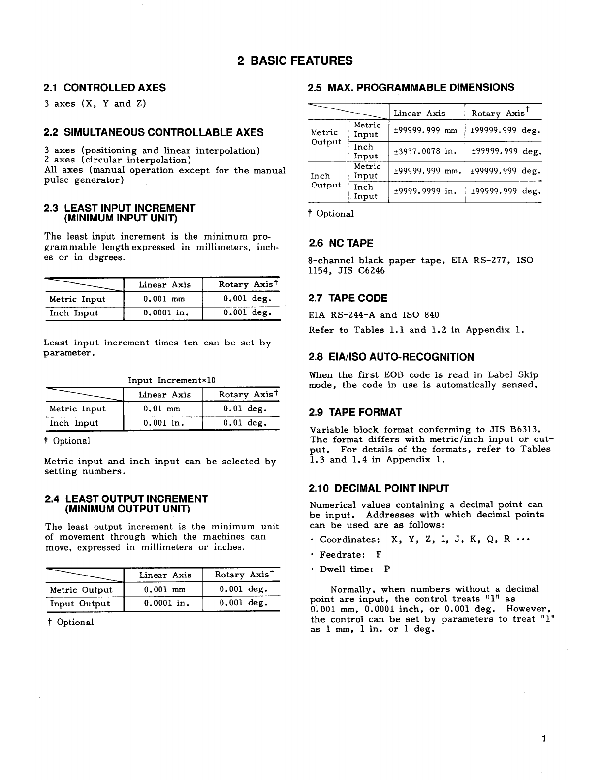
2.5 MAX. PROGRAMMABLE DIMENSIONS
Inch
output
t Optional
Metric
Input
Inch
Input
+99999.999
f9999. 9999 in.
mm.
*99999.999 deg.
t99999. 999 deg.
2.6 NC TAPE
8-channel black paper tape, EIA RS-277, ISO
1154, JIS C6246
2.7 TAPE CODE
EIA RS-244-A and 1S0 84.0
Refer to Tables 1.1 and 1.2 in Appendix 1.
2.8 EIA/lSO AUTO-RECOGNITION
Input Increment X10
Linear Axis
Metric Input 0.01
mm 0.01 deg.
Rotary Axis f
Inch Input 0.001 in. 0.01 deg.
t Optional
Metric
input and inch input can be selected by
setting numbers.
2.4 LEAST OUTPUT INCREMENT
(MINIMUM OUTPUT UNIT)
Ths least output increment is the minimum unit
of movement through which the machines can
move, expressed in millimeters or inches.
Rotary Axis+
0.001 deg.
0.001 deg.
Metric Output
hmut OutPut
t Optional
Linear Axis
0.001 mm
0.0001 in.
When the first EOB code is read in Label Skip
mode, the code in use is automatically sensed.
2.9 TAPE FORMAT
Variable block format conforming to JIS B6313.
The format differs with metric /inch input or out-
put .
For details of the formats, refer to Tables
1.3 and 1.4 in Appendix 1.
2.10 DECIMAL POINT INPUT
Numerical values containing a decimal point can
be input.
can be used are as follows:
“ Coordinates: X, Y, Z, I, J, K, Q, R
“ Feedrate: F
“ Dwell time: P
Normally, when numbers without a decimal
point are input, the control treats “ 1“ as
01001 mm, 0.0001 inch, or 0.001 deg. However,
the control can be set by parameters to treat “ 1”
as 1 mm, 1 in. or 1 deg.
Addresses with which decimal points
● . .
1
Page 9

2.11 BUFFER REGISTER
During normal operation, one block of data is
read in advance and compensation is computed
for the follow-on operation.
In the tool radius compensation~ C mode, two
blocks of data or up to 4 blocks of data are read
in advance and compensation computing required
for the next operation is executed. One block
can contain up to 128 characters including EOB.
Feedrate (Feed/Minute)
Range
F1. - F30000 mm/min
FO.1 -F1181.10in. /rein
Metric Input
output
Metric
Inch
Input
Format
F40
F31
“’UHH==
2.12 RAPID TRAVERSE RATE
Up to 30,000 mm/min, or 1181.10 in. /rein, as set
by parameters, is programmed independently for
each axis.
2.13 FEEDRATE RANGE
Feedrate is programmable between 1 and 30,000
mm/min, or between 0.1 and 2400 in. /min.
upper limit can be set by parameters according
to the machine.
The
2.14 AUTOMATIC ACCELERATION /
DECELERATION
(1) In positioning and manual feeding, motion can be
automatically accelerated and decelerated linearly. Twostage linear acceleration/deceleration can also be set as
shown below, independently for each axis.
v
Note:
1/10 by parameters.
Minimum input values can be reduced to
2.16 FEEDRATE OVERRIDE AND FEEDRATE
OVERRIDE CANCEL
Rapid traverse rate override
(1)
Rapid traverse rates can be reduced to FO, 25%,
50% or 100% of the original traverse rate. FO is
set by parameters.
(2) Feedrate override
The feedrates programmed by F codes can be
modified between O% to 200% in 10% increments.
(3) Feedrate override cancel
When this switch is turned on, any feedrate
override ef feet is cancelled, and the tool moves
at the originally programmed feedrates.
2.17 PREPARATORY FUNCTIONS
(G-FUNCTION)
G codes consisting of address G plus up to 3
digits, specify work for the respective blocks.
For details of the G codes, refer to Table 1.5 in
Appendix 1.
t
(2) Feed acceleration is exponential, and is
applled commonly to all the axes.
v
The time constants for the above curves are set
by parameters.
2.15 FEED FUNCTION (F-FUNCTION)
Tool feedrates are selected within the following
ranges by F codes.
2
(1) Ordinary G codes include non-modal G-codes
marked with*, and modal G-codes belonging to
groups 01 through 15.
long to division B are basic G-codes.
(Z) G1OO through G199 are expansion G-codes.
They are used ~o call G-codes for
option, etc.
The G-codes which be-
user macro
2.18 ABSOLUTE/lNCREMENTAL
PROGRAMMING (G90/G91 )
With the following G-codes, the tool movement
can selectively be programmed either in absolute
values or in increments:
G90 :
G91: incremental designation
absolute designation
2.19 PROGRAMMING OF ABSOLUTE ZERO
POINT (G92)
With a command “G92 X... Y.. . Z. ..:,” an absolute coordinate system is established with the
current tool position having the specified coordinate values.
Page 10

2.20 POSITIONING (GOO,G06)
(1] GOO X... Y... Z... ;
With this command, the tool moves at the rapid
traverse rate to the specified coordinate position,
moving independently in each coordinate direction.
The motion after positioning will be in the ERROR
DETECT ON mode. GOO is a 01 group modal G
code. The ERROR DETECT OFF mode can be
entered by parameters.
180”OR OVER
(2) G06 X... Y... z... ;
with this command, after executing. a positioning
similar to GOO, the program advances to the next
block in the ERROR DETECT OFF mode. G06 is
non-modal, and is effective only in the programmed block.
Note:
In the ERROR DETECT ON mode, the
command of the next block is executed only after
the servo-lag pulses in the current block are
reduced to a permissible number. The ERROR
DETECT OFF mode is where the command of the
next block is executed immediately after the distribution of the pulses in the current block, regardless of the servo–lag pulses. In this mode,
the corners of the workplaces are slightly
rounded.
2.21 LINEAR INTERPOLATION (GOI)
GOI X... Y... Z... F... ;
With this command, the tool moves along the
specified straight line at a feedrate specified by
the F code.
2.22 CIRCULAR INTERPOLATION (G02, G03)
START POINT
G02 X... Y.., Rt... F... ;
(3) G02 (G03) I... J... F... Ln;
This command moves the tool around a
designated complete circle n times. When L is
not programmed, the tool moves only once
around the circle.
(4) G codes for plane designation (G17 to G19)
The plane for programming circular interpolation
is specified by the following G codes:
G17:
G18:
G19:
XY plane
2X plane
YZ plane
Note :
1. Circular interpolation is possible over two or
more quadrants.
2. Circular interpolation is also possible with
respect to the optional 4th linear axis.
2.23 DWELL (G04)
(1) G02 (G03) X... Y... I... J... F... ;
These commands move the tool along the specified circular path at feedrate specified by the F
code.
X and Y specify the end point of the circular motion, and I and J specify the center of
the circular path in XY plane. With the proper
selection of address, similar circular interpolation
is programmed also in the XY and ZX planes.
G02 is for clockwise motion, and G03 is for
counterclockwise motion.
(2) G02 (G03) X... Y... R... F... ;
Circular interpolation is also possible by desig-
nating the radius R with the above command.
When R > 0, a circular path with a center angle
smaller than 180° is programmed, and when R c
O, the center angle of the circular path is larger
than 180°.
G04 P...;
With this command, the tool remains motionless
for the duration of time specified by the P code.
The minimum and the maximum programmable
dwell times are 0.001 and 99999.999 seconds,
respectively.
2.24 EXACT STOP CHECK (G09, G61 , G64)
This function is effective only in the blocks of .
feedrate which is controlled by interpolation.
(1) Exact stop (G09)
A block containing G09 is executed in the
ERROR DETECT ON mode.
is required to be machined with a sharp corner,
this code is programmed.
is effective only in the programmed block.
(2) Exact stop check mode (G61)
When G61 is programmed, all the subsequent
blocks are executed in the ERROR DETECT ON
mode until G64 is programmed.
When the workpiece
G09 is non-modal, and
3
Page 11

2.24 &W#TOP CHECK (G09, G61 , G64)
(3) Exact stop check mode cancel (G64)
This code is for canceling the G61 command.
In either output mode, spindle speed
override can be accomplished.
permits overrides by steps of 10% within a range
of 50 to 120% to the spindle output command.
(Input points: 3)
This function
Note:
1. When the power supply is turned on, the
status corresponding to G64, that is, the
ERROR DETECT OFF mode, is on.
2. Rapid traverse motion is controlled by GOO
and G06, and not influenced by these exact
stop G codes.
2.25 MISCELLANEOUS FUNCTION
(M-FUNCTION)
Miscellaneous functions are programmed with address M and up to these digits. The M codes
are grouped in the following three categories:
(1) M codes for internal processing, decode sig-
nal outputting, and 3-digit BCD outputting.
MOO:
MO1:
M02:
M30:
(2) M
M90t:
M91~:
M92t:
M93t:
M94:
M95:
M96t :
M97+:
M98:
M99:
M1OO to 199: - f indicates options.
(3) M codes exclusively for outputting 3-digit
BCD signals are those other than the above.
Program stop
Optional stop
Program end (reset)
Tape end (reset and rewind)
codes only for internal processing
Program interrupt off
Program interrupt on
Multi-active register off
Multi-active register on
Mirror image off
Mirror image on
Tool radius compensation C; circular path
mode
Tool radius compensation C; intersection
calculation mode
Subroutine program call
Subroutine program end
2.26 SPINDLE-SPEED FUNCTION (S-FUNCTION)
Instead of this function, S5-digit
programming with 12-bit output is selected. It
outputs 12-bit binary signal without a sign
(4095 maximum) .
2.27 TOOL FUNCTION (T-FUNCTION)
Tool numbers are specified by two digits following the address T.
are sent in 2-digit BCD.
Note:
output is available as an option.
T4-digit programming with T4-digit BCD
Commands to the machine
2.28 TOOL LENGTH COMPENSATION
(G43, G44, G49)
This is a tool position offset function only effective in the Z-axis direction. With G43 ( G44)
Z H...
. . .
offset by the value stored in the tool offset
memory specified by the H code in plus (+) or
minus (-) direction, with respect to the point of
the Z-axis movement.
G Code
G43
G44
G49
Note: When power is applied, the control is in
the state of G code marked with
; or G43 (G44) H. . . ; the tool is
Meaning
Tool length compensation in plus (+]
direction
Tool length compensation in minus (-)
direction
1
Tool length compensation command
cancel
1“
2.29 TOOL POSITION OFFSET
(G45 THROUGH G48)
These tool position offsets are used mainly for
compensating for the radius differences when
machining simple rectangular workplaces.
The following output mode can be selected.
S 5-digit programming, analog output (Basic
option). Outputs analog voltage of t10 V max
as D /A converter.
The control outputs spindle gear ratio change
commands (4 max) when it receives the RPM
value specified program.
analog voltage corresponding to the changed
gear ratio.
changed gear ratio. Speed ranges for
individual gear ratio are set by parameter.
Speed ranges corresponding to the
It then outputs
4
G01G45 (G46) X... D... F... ;
With this command, the feed lehgth of the tool in
the specified axis is extended or retracted by
the length stored in the specified tool offset
memory.
G Code
G45
G46
G47
G48 I Double retraction
I
Extension
Retraction
I
Double extension
I
Meaning
Page 12

These G codes are non-modal, and are effective
only in the block in which they are programmed.
When circular interpolation is included in the
same block in which a tool position offset is pro–
grammed, the radius and the end point are extended also.
In this case
~ proper compensation
for tool radius is possible only for machining
1/4, 3/4 and 414 circles.
2.30 OFFSET MEMORY
The two digits following the address H or D are
called tool offset numbers, and these numbers
are assigned to the 99 tool offset values stored
in the tool offset memory.
set value can be designated with the tool length
compensation command (specified by the H code)
or the tool position offset command (specified by
the D code among the stored values.
Note: The 99 tool offset values can also be used
with the tool radius compensation C function
(option).
Up to 299.
Tool offset memories can be expanded
Any desired tool off-
(3) Step feed (STEP)
Each time the desired JOG button is pushed, the
tool moves through the distance specified by the
MANUAL PULSE MULTIPLY switch. The distance are in the following multiples of pulses:
x 1,
x 100, x 1000, x 10,000, x 100,000.
x 10,
2.34 PROGRAM STORAGE AND EDITING
Part program can be loaded into memory for
tapeless operation and for editing.
(1) Memory capacity is equivalent to 40 meters of
tape. (Note 1)
(2) Part program, added with a program number
of 4-digit numerals, can be stored in memory
(from paper tape or MDI).
up to 99 program numbers can be stored in memory.
(Note 2)
(3) The stored part program can be edited by
ERASE, INSERT, and ALTER keys. Editing is
done in one to several words at a time.
In the basic mode,
2.31 TOOL OFFSET VALUE
The range of tool offset value that can be
written in the tool offset memory is as follows:
Metric Input
Inch Input O to +99. 9999 inches
O to t999. 999 mm
2.32 BACKLASH COMPENSATION
This function is for compensating for the
backlash in the driving system of the
machines, Backlashes between O and +8191 P
can be compensated independently in each axes
(p representing the minimum output unit).
The desired compensation values are preset by
parameters.
2.33 MANUAL FEED
Manual feed is possible in the following three
modes, simultaneously in all three axes.
(1) Manual rapid traverse (RAPID)
The tool moves at the rapid traverse rate, in-
dependently in all three axes.
(2) Manual JOG feed (JOG)
After setting the JOG FEEDRATE switch at he
desired speed (32 available) , the tool will move
at that feedrate while any of the JOG buttons is
depressed.
(4) The OUT, VER, and IN keys are used to
output the stored part programs to external
equipment (option) , to collate them with punched
cards, and store them from tape readers.
(Note
3)
(5) Address search function permits the specified program number to be searched for the pur-
pose of an automatic operation (MEM mode).
Note:
Optionally, the part program storage may
1.
be extended to 320 meters.
2. Optionally, the number of stored programs
may be extended to 999.
3. To output the part program to an external
equipment, the optional 11data input/output
interface
11is required.
2.35 SUBROUTINE PROGRAM (M98, M99)
Subroutine programs with program numbers can
be retrieved and executed as many times as de-
sired.
(1) Retrieving subroutine programs (M98)
M98 P... L... ;
With this command, the subroutine program with
the number designated by P is retrieved and
executed L times.
the subroutine program is executed only once.
The retrieved subroutine program may also retrieve further subroutine programs up to four
nestings.
When no L-digit is defined,
5
Page 13
2.35 ~W~:)UTINE PROGRAM (M98, M99)
(2) Subroutine program end (M99)
Subroutine programs are written in the following
format, and stored in the part program storage
in advance.
o
. . . . . . . . . . . .
. . . . . . . . . . . . . . .
.*. .*...*. . . . . .
i
..
I
..0...... ● .**
. . . . . . . . . . . . . . .
M99 ;
;
1
:
:
;
:
Program No.
. . .
I
I
Subroutine program
. . .
I
2.40 ADDRESS SEARCH
All address data, including program numbers in
the part program storage can be searched with
an MDI command.
2.41 PROGRAM NUMBER
Up to 4 digits can be written as program
numbers immediately after the address O,
However,
numbers that can be registered is 99.
program starts with a program number, and ends
with M02, M30 or M99.
the maximum number of program
A part
2.42 LABEL SKIP
(3) Special use of M99
M99P... ;
With this command, the control does not advance
to the subsequent block after executing the sub-
routine program, but returns to the block with
the sequence number specified by P.
2.36 PARAMETER SETTING
Parameters for machine constants such as back-
lash compensation values and rapid traverse
rate can be written.
2.37 SETTING FUNCTION
Any of the functions can be selectively switch-
ed on and off.
2.38 INTERNAL DATA TAPE INPUT
Normally, tool offset values, parameter data, and
setting data are input from MDI.
function, these data can be entered into the re-
spective memories via tape reader.
With ordinary part programs, any desired tool offset
values can be changed into desired tool offset values
can be changed into new values with the command
“G1O P... R... ,
set value).
(P = tool offset number, R = tool off-
With this
2.39 OPERATION TIME DISPLAY
With this function, the cumulative times of the
following operations can be displayed:
(1) Total time after switching the power supply
on
(2) Total time of automatic operation
Total automatic cutting (interpolation motion)
(3)
time
The Label Skip function becomes effective and
LABEL SKIPII is displayed when:
!!
(1) the power supply is turned on,
(2) control is reset.
When the Label Skip function is effective, all the
tape information before the first EOB code is ignored. When LABEL SKIP lamp is on in the MEM
or EDIT mode, it indicates that there is a
pointer at the beginning of the part program.
2.43 CONTROL iN/OUT
Data between a control out” (11 and control in
‘1)” is ignored as insignificant.
2.44 TV CHECK
This function checks whether the number of
characters including EOB is odd or even. If the
number is odd, the block is regarded as an in-
put error, and the operation is interrupted auto-
matically.
with parameters.
Note: The TV check does not count the characters between control out and control in.
This function is turned on and off
2.45 SEQUENCE NUMBER BREAK POINT
During automatic operation, a single-block-stop
can be applied after the execution of a block by
specifying the sequence number of the desired
block .
a break point, and up to 2 break points can be
set wit h the setting function.
The specified sequence number is called
2.46 SINGLE BLOCK
While the SINGLE BLOCK switch (at the
machine side) is turned on, automatic operation
with tape or the memory are performed block
by block.
6
Page 14

2.47 OPTIONAL STOP
While the OPTIONAL STOP switch (at the
machine side ) is on, operation stops automatically
after executing a block including MOI.
OPTIONAL BLOCK SKIP
2.48
2.55 MIRROR IMAGE
Mirror image axis for symmetrical machining can
be specified with switches (for X, Y or the 4th~
axis).
tool path between M95 and M94 on the program
with respect to the specified axis.
Mirror image control is applied to the
While the OPTIONAL BLOCK SKIP switch (at
the machine side) is on, a command block
starting with “/” is neglected.
2.49 DRY RUN
With this function, the feedrates for automatic
operation are converted into manual operation
feedrates for convenience during dry-run. While
the DRY RUN switch (at the machine side) is
on, the following feedrates are available,
DRY RUN On
Feed
Rapid
Traverse Feed (Parameter Selection )
Feedrate for Manual Continuous Feed
Rapid Traverse or Manual Continuous
2.50 MACHINE LOCK
This function allows NC commands to be execut-
ed, with M, S, and T functions functioning normally, and the current positions to be continuously updated and displayed, with the machine
standing still.
2.56 INTERNAL TOGGLE SWITCHES
With this function, the toggle switches for the
function described in paragraph 2.47 SINGLE
BLOCK through 2.56 MIRROR IMAGE can be
eliminated at the machine control station, and
the necessary setting can be performed from the
NC operator’s station.
2.57 ORIGIN KEY
The ORG key designates the current tool
position designated at point “O. ” Each axis is
controlled independently.
2.58 iNTERLOCK
Tool movement for control axes can be locked
during motion with this function. When interlock is applied, the tool stops after deceleration,
and when interlock is cleared, the tool resumes
the motion.
When interlock is applied during an interpolation covering two or more axes, the interpolation motion is stopped.
DISPLAY LOCK
2.51
With this function, the POS-EXTERNAL display
Is locked while the machine is operated under
automatic or manual control.
2.52 Z-AXIS COMMAND NEGLECT
While Z-AXES NEGLECT switch is on, the
machine motion only in the Z–axis is locked.
2.53 AUXILIARY FUNCTION LOCK
While this switch is on, no BCD code
for M, S, and T (and BY) functions.
MANUAL ABSOLUTE ON/OFF
2.54
While this switch is on, manual movement dis-
tances are added to the absolute register, and
the coordinate system remains unchanged. While
the switch is off, manual movement distances are
not added, and the coordinate system is shifted
in parallel with the movement.
is output
2.59 START LOCK AND EDIT LOCK
The following functions can be turned on and
off by switches.
(1) START LOCK
When this function is on, the CYCLE START
key is made ineffective.
(2) EDIT LOCK
When the EDIT LOCK is on, editing and storing
of part programs are inhibited.
2.60 AUTOMATIC COORDINATE SYSTEM
SEITING
With this function, a new coordinate system
having coordinate values set by parameters in
advance is automatically set up at the reference point after executing manual return to
reference point. The coordinate system
established by this function is equivalent to
the one set by G92.
7
Page 15

2.61 FEED HOLD
The feedhold function interrupts tool feed temporarily during automatic operations.
Feedhold operation is disregarded during
threading.
2.62 EMERGENCY STOP
This function makes all the commands ineffective.
The servo power supply is turned off, and all
moving members of the machine are stopped by
dynamic brake.
2.63 OVERTRAVEL
With this function, the tool motion is stopped
upon receipt of a stroke-end signal from the
machine. When the machine is stopped by this
function, the machine member must be moved
backward by manual feed.
REMOTE RESET
2.64
With this function, the NC is reset with an
external signal. When the NC is reset, all the
commands become ineffective, and tool motion is
stopped immediately.
2.65 REMOTE POWER ON/OFF
2.69 NC RESET OUTPUT SIGNAL
While RESET key or REMOTE RESET key is depressed, an NC reset signal is output to the
machine.
RS-232C INTERFACE
2.70
RS-232C interface is provided in order to connect
with tape puncher, external tape reader or other
external devices.
Interface Type
Communication Speed
Connector I DB-25S
Maximum Cable Length 15 m
outmt from Memorv Possible
Storage in Memory
Tape Mode Opertion Possible
Note :
The following are the data items which are
objects for output from memory and storage in memory.
Part program
(a)
Offset data, machine tool coordinate data, machine
(b)
tool abrasion data
(c)
Setting and parameter data
Serial Voltage Interface
110 to 4800 baud
I Possible
In addition to the POWER ON/OFF keys on the
NC Operatoris station, the control is provided
with input terminals for receiving remote power
onloff signals.
2.66 MACHINE READY INPUT SIGNAL
When the machine is ready for operation, this
signal is transmitted from machine to control.
When this signal is received with the control in
the “NC ready” condition, operation may be
started immediately.
When this signal drops off during operation,
IImachine errorll status occurs, and all the functions become ineffective.
2.67 NC READY OUTPUT SIGNAL
When the NC is correctly energized, and is
ready for control function, an “NC ready” signal
is output to the machine.
2.68 NC ALARM OUTPUT SIGNAL
When one or more alarm states are present, an
NC alarm signal is output to the machine. When
the cause is eliminated and the reset procedure
is followed, this signal is stopped.
2.71 ON-LINE DIAGNOSTICS
During operation, the following self-diagnoses are
made online:
(1) 3-digit Alarm Code and Alarm Message Display.
System
(2
System memory total check.
a.
b.
RAM check (when power is input).
Watchdog timer.
c.
Diagnosis
(3) Input /Output Signal Diagnosis
2.72 POSITION DETECTOR INTERFACE
Position detected by feedback signal from the
rotary-type pulse generator.
rotation of the pulse generator is varied by the
number of pulses from the pulse generator as
shown below.
Pulse
Generator
Metric
OutPut ] ~ooCI p/rev I 2, 3, 4, 6, 8 mm
5000 plrev
5000 plrev
Inch
output 6000 plrev
2.5, 5, 10
0.25, 0.5
0.2, 0.3, 0.4,
0.6. 0.8
The motion per
Motion per Rotation
of Pulse Generator
mm
in
in
8
Page 16

The motion per rotation of the pulse generator
of X-axis becomes one-half of the above values.
Note: Pulse multiplication can be set by servo
unit or NC.
2.73 lNPUT/OUTPUT CONNECTORS
The control is connected with the machine control
circuit via “Half pitch connectors. ”
(2) Relative humidity: 10 to 90% R. H.
(3) Vibration: 4.9 m/s2max
Note: When the ambient conditions do not con–
form to the above requirements, or when organic
solvent or other fumes are present in high concentration we offer special measures.
2.76 PAINT COLOR AND DIMENSIONS
2.74 POWER INPUT A
Standard input
200/220/230 VAC +10%, –15%, 3-phase, 50/60 Hz,
~1 Hz
2.75 AMBIENT CONDITIONS
Ambient temperature:
(1)
for operation: O°C to 45°C (32°F to 113QF)
for storage: -20°C to +65°C’ (-4°F to +149°F)
3 BASIC OPTIONS
The optimal servo components are available for
selection to meet the requirements of the machine
being controlled.
3.1 AC SERVO CONTROL UNITS
Transistorized PWM AC servo control units are
further miniaturized to be available for use in
either or the following systems:
(1) NC board built-in system: Free standing
type.
(2) External system: Supplied in unit.
Connection cable should be 10 m max.
Servo capacity is as follows:
Series Motor
No Maximum Continuous
11
2 60
3
4
5
6
F
Torque
kg . cm
30
90
120 CACR-SR20SB1 •l F
230 CACR-SR30SB1
380
SERVOPACK Type
\ CACR-SR05SB1
CACR-SRIOSB1
CACR-SR15SB1
CACR-SR44SB1
❑ F
❑ F
❑ F
❑ F
❑ F
(1) The following dimensions are available for the
selection to suit the machine to be controlled.
‘ Control unit
150 (W) X350 (H) X185 (D) mm
5.90 (W) X13.78 (H) X7.28 (D)
(2) Paint Color
o NC operator’s station: Munsell N1. 5 (gray)
“ Enclosure inner louter surface: Munsell
4Y7.7/l.2 (light gray)
3.2 AC SERVOMOTORS
The following AC servo motors that incorporate
the feedback unit, consisting of position-detecting
pulse generator ( PG ) and speed-detecting tacho-
meter generator (TG ).
No Maximum Continuous
* According to the type of detector, either A or B is
F Series Motor
Torque
kg . cm
1
2
3
4
5
6 380
entered in
A : 6000 p/rev
B : 5000 p/rev
30
60
90
120
230
❑l.
SERVOMOTOR Type
I
USAFED-06FO*
USAFED-09F ❑
USAFED-13F •1
USAFED-20F
USAFED-30F •1
USAFED-44F •1
❑
9
Page 17

4 OPTIONS
4.1 NC OPERATOR’S STATION
The separate stations are available
rations :
. Keyboard on right side of CRT
See Fig. A2.2.
. Keyboard below CRT
See Fig. A!Z3.
in three configu-
4.2 TAPE READER
The tape reader unit specified below can be provided
as an independent unit or incorporated in a freestanding cabinet. For connections of the tape reader, RS-232C interface is used.
. Read speed :
“ Reading system : LED-photoelectric
200 char. /see
4.3 TAPE READER WITH REELS
Free-standing type cabinets can be provided with
the following tape reader with reels. Tape reel
unit can be provided as an independent unit.
(1) 6-inch reel
Reel diameter:
Tape length:
(2) 8-inch reel
Reel diameter:
Tape length: 180 m (590 ft. )
150 mm (6 inches)
80 m (262 ft. )
200 mm (8 inches)
4.6 T4-DIGIT PROGRAMMING
Instead of the basic T 2-digit programming, tool
numbers can be programmed with 4 digits following the address T.
sponding 4-digit BCD code.
The control outputs corre-
4.7 ADDITIONAL OFFSET MEMORY
Basic offset memory capacity of 99 can be
expanded up to 1199.
4.8 ADDITIONAL PART PROGRAM STORAGE
Instead of the basic part program storage of tape
length 40 m (131 ft. ) the following are available.
1
11
21
31
Tave Length
80 m (262 ft. )
160 m (524 ft. )
320
m (1049 ft. )
4.9 ADDITIONAL PROGRAM NUMBER
REGISTRATION
Either of the following number of registrable
programs can be selected to replace the basic
number of 99.
The indicated tape lengths are for tapes with
0.108 mm (4 inches) thickness. The following
are common to both reader.
Read speed: 200 char. /see
Rewind speed: 200 char. /see
Reading system: LED photoelectric
4.4 F1-DIGIT COMMAND
With this function, feedrates can be programmed
by one digit following an address F (Fl through
F9).
through F9 are preset by parameters.
mm/min commands of the ordinary F-function
(direct designation of feedrates in mm/min) can-
not be used.
The actual feedrates corresponding to F1
When this function is adopted, 1 through 9
4.5 S5-DIGIT PROGRAMMING WITH
12-BIT OUTPUT
S 5-digit programming with 12-bit output S
5-digit programming analog output can replace
S 5-digit programming 12-bit output specification.
The output is made by 12-bit binary (4095
maximum) signal.
10
2
I
Note that if the optional ‘1additional program
number registration”
capacity for the part program is reduced by the
following amount.
Additional Number Reduced
of Registered Programs
199
999
999
is adopted, the storage
Storage Capacity
2 m (6.6 ft. )
18 m (59 ft. )
4.70 4TH AXIS CONTROL
Any one out of the three rotary axes A, B and
C and linear axes, U, V and W, can be
controlled as 4th axis in addition to the three
basic axes.
are possible.
.
Simultaneous controllable 4 axes:
Positioning (GoO, G06, G60)
Linear interpolation (GO1 )
Manual feed except by manual pulse generator
The following simultaneous controls
Page 18

.
Simultaneous controllable 2 axes:
Circular interpolation (G02, G03)
●
For linear 4th axis, stored stroke limit can
be set at 1st prohibit area only.
✎
Program Restart, User Macro, Stored Leadscrew Error Compensation are effective with
the 4th axis.
✎
Tool Length Compensation, Tool Compensation
C, High-~peed Cutting are ineffective ‘with the
4th axis.
4.11 MANUAL PULSE GENERATOR FOR ONE
AXIS AT A TIME
With the manual pulse generator, the machine
can be moved in response to the manual turning
of the pulse generator by handle.
The generator has a dial graduated into 100, and the
travel distance per graduation can be set to 1,
10 and 100 pulses. The controlled axes are
selected with the select switch, and the tool is
controlled only in the selected axial direction.
4.12 REFERENCE POINT RETURN
(G27, G28, G29)
AH of the following methods for returning the
tool to the reference point are possible.
(1) Manual return to reference point
After the ZERO RETURN switch is turned
on, the tool can be returned to the reference
point by manuztl operation. The approach speed
and the traverse distance are set by parameters,
RATIO TRAVERSE RATE
v
h---J-/
i
APPROACH SPEED 1
APPROACH SPEED 2
(3) Autcxmtic return to reference point (G28)
X... Y.. . Z.. . ;
G28
With this command, the tool first moves to the
specified intermediate position, and from there,
automatically returns to the reference point.
(4) Return from reference point (G29)
G29 X... Y... Z... ;
With this command, the tool starts from the re-
frence point, moves through the intermediate
point specified by G28 previously, and finally
moves to the position specified by G29.
(5) Rapid return to reference point
The manual and automatic reference point return
motions can be made in rapid return mode by
specif yin g in the specifications.
In this rapid
return mode, the tool does not follow the deceleration sequence started by decelerations LS, but
moves directly to the reference point as if the
tool were moving in the GOO positioning mode.
This rapid return mode becomes effective,
however, only after the tool has been once
returned to the reference point in all axes in
the
normal mode.
4.13 ;JD, AND 4TH REFERENCE POINT
G30Pn X,,. Y... Z.. .
With this command, the tool is returned to the
2nd, 3rd, or 4th reference point after position-
ing in the specified intermediate position.
P2 :
2nd reference point
P3 :
3rd reference point
P4 : 4th reference point
The reference points can be set by parameters.
; (Pn = P2, P3, and P4)
4.14 EXTERNAL DECELERATION
‘---~ZERO POINT SIGNA
(2) Reference point check (G27)
G27 X... Y... Z... ;
With this command, the programmed point is
checked for coincidence with the reference point.
If the programmed point does not coincide with
the reference zero point even in one axial direc–
tion, this is regarded as an error.
When an external deceleration limit switch is
tripped, the tool speed, both, rapid traverse and
feed, are reduced to the levels set by parameters.
This switch can be installed in both directions on
all axes.
TOOL LENGTH MEASUREMENT
4.t !5
With an actual tool mounted on the machine
spindle, the tip of the tool is brought to the
base position for the Z-axis by manual operation,
and RETRACT button is pushed.
Then, the
control executes the following operations:
(1) Automatic storing of the distance from the
home position in the Z-axis to the current position in the tool offset memory at the specified
tool offset number.
11
Page 19

4.15 TOOL LENGTHMEASUREMENT (Cont’d)
(Z) Increasing the tool offset number by “l” in
preparation for the next write operation.
(3) Returning the tool to the Z-axis home posi-
tion.
Note:
1, Instead of “moved distance, “ “remaining dis-
tancell can be stored by parameters.
2. Instead of pushing the RETRACT button, the
appropriate key on the NC Operator?s Station
may be depressed for tool length measurement.
The tool does not return to the home position.
W
MODE
DISTANCE
% T.
RETURN
[
a
HOME POSITION
BASE POSITION
4.19 PROGRAM COPY
G25
P,...,, Q,.l,,...I,... ,L
pl p2 ql q2
This command executes any
sequence p2 of program
program ql, L times.
the program one time.
the copied program. Nesting up to 4th level can
be applied.
During canned cycles, program copy
can be commanded.
.*.
;
program from
pi to sequence q2 of
Omission of L executes
G25 can be commanded in
4.20 HELlCAL INTERPOLATION (G02, G03)
Circular interpolation in any desired plane can
synchronously combined ‘with a linear inter-
be
polation perpendicular to the plane of circular
interpolation. For example, with G02 ( G03) X. . .
Y I.. . J... Z.. . F...
. . . ; , circular interpolation
in the XY plane is combined with linear interpolation in the Z–axis.
4.16 OPTIONAL BLOCK SKIP B
In addition to the ordinary block skip (programmed with
built into the control.
grammed with codes “ /2” through “ /9, ” and when
the respective switches are on, these blocks
are skipped.
H /II or fl / 1 II ) , !3 skip functions may be
These functions are pro-
4.17 2ND AUXILIARY FUNCTION (B-FUNCTION)
2nd auxiliary function command can be used with
three digits following address B.
outputs the corresponding 3-digit BCD code to
the machine.
Note:
the control, the B-axis for 4th axis or 5th axis
control cannot be adopted.
When this B function is incorporated in
The control
4s18 JOG FEEDRATE OVERRIDE
This function permits overrides in 21 steps of
10% per step within a range of O to 200% in
relation to the jog feedrate.
OVERRIDE switch serves as the FEEDRATE
OVERRIDE switch.
JOG FEEDRATE
Note:
Instead of I, J and K, arc center can be
1.
specified by radius R.
2. Helical interpolation is also possible with a
4th axis which is a linear axis.
3. Tool radius compensation C is effective only
on the circle projected on the plane of
circular motion.
4.21 CIRCLE CUTTING B (Gl 2, GI 3)
With this function, all the motions involved in
cutting a circle can be programmed in one block.
(1) Rapid approach distance designation R
G12 (G13) 1... R... D... F... ;
With this command, the circle cutting operation
shown below is executed.
distance is specified by R.
The rapid approach
12
Page 20

Y-AXIS
OOL
With this command, the tool moves along a spiral
path as shown below to cut a circle. For the
sake of simplicity, an imaginary tool with the
radius D = O is shown.
X-AXIS
Tool path
G12: 1—2—3—4—5—6
G13: 6—5—4—3—2—1
(D) indicates tool offset value specified.
G12 is for CW and G13 is for CCW.
I: radius of finished circle (with sign, incre-
mental)
R: rapid approach distance (with sign, incremental)
D: tool offset number
F: feedrate
(2) Automatic calculation of rapid approach dis-
tance
G12 (G13) I... J... D... F... ;
When the cutting depth is designated incrementally by the address J, instead of three distance
R, the rapid approach distance just short of the
tool contact point ot the stock surface is
automatically calculated.
Note:
Y-AXIS
This function incorporates the tool radius
G12: 1 *2-3-4-
A
w
5+6
INCREMENT OF
RADIUS
X-AXIS
K: RADIUS OF
FINISH CIRCLE
compensation function.
4.22 lNCH/METRIC DESIGNATION BY G CODE
With the following G codes, metric and inch input
system are selectively designated.
=
Y-AXIS
1
s
P
J : CUT
.—,
I
(3) Repetition of circular motion by L
G12 (G13) I.. D.. . J... L.. . F... ;
With this command, the circular motion is re–
peated L times.
(4) Spiral circular cutting by Q and
G12 (G13 ) I.. . D.. . J.. . K.. . Q.. . L... F... ;
K
These G codes are written at the beginning of a
program in a single block.
Note:
1. G20 and G21 commands rewrite inch/metric
selecting parameter.
of G20 or G21 at power switch-on time depends
on the parameter.
2. The inch/metric selection by parameter set-
ting is a basic function.
Therefore, the condition
4.23 UNIDIRECTIONAL APPROACH (G60)
G60 X... Y... z.. . ;
With this command, the tool is brought to the
specified position. However, in the direction
specified by parameter only the tool first over-
runs and returns to the specified position.
The
overrun distance is set by parameters.
This G60 command is effective to stop the tool
with high accuracy.
13
Page 21

4.24 WORK COORDINATE SYSTEM SETTING A
(G52 TO G59)
With this function, tool motion can be programmed in the following coordinate system, in addition to the basic coordinate system set up by the
G92 command.
4.26 TOOL RADIUS COMPENSATION C
(G40 TO G42)
This function is for automatically offsetting the
tool path to the right or to the left of the programmed path by a distance equal to the radius
of the tool used.
(1) When any of the G codes from G54 through
G59 is programmed, a new coordinate system
which is shifted from the basic coordinate system
by a preset amount for the selected G code is
established.
system is referred to as a work coordinate
system, and thereafter, the tool is controlled on
the work coordinate system.
coordinate systems can be set up for use.
(Z) Return to the basic coordinate system ( G52)
G52 ;
With this command, the current work coordinate
system is can celled, and the basic coordinate
system is re-established.
(3) Temporary shift to machine coordinate sys-
tem (G53)
During the execution of programs on a work
coordinate system or on the basic coordinate sys–
tern, the tool may temporarily be shifted to the
position (X,
system with a command G53 GOO X.. . Y.. . Z.. . ;.
G53 is a non-modal G code. The machine coordinate system is one in which the origin is the reference point.
This newly established coordinate
Up to 6 work
Y, Z) on the machine coordinate
Yw
YM
I
(1) The meaning of these G codes is as follows.
G Code ! Meaninz
G40
G41
G42
Note: When power is applied or the control is
reset, the control is in the state of G code
marked with 1 .
TOOL
(2) D code for tool radius designation
Tool offset numbers are specified by two digits
following address
values are stored in the tool offset memory corresponding to these tool offset numbers.
maximum tool radius that can be set is as
follows :
+999.999 mm
?99. 9999 in.
Cancel tool radius compensation
7
Tool radius compensation , left
I Tool radius compensation, right
G40
G41
/’
\’ \
\\
/“. - “,
G42
‘\
%
b
CENTER
The actual tool radius
D.
PROGRAM
COMMAND
The
-x.
1)
BASE COORDINATE SYSTEM
(
)
ABSOLUTE ZERO POINT
4.25 WORK COORDINATE SYSTEM SETTING B
(G54J TO G59J)
This is the expansion function of work coordinate
system setting A. Up to 30 types of work coordinate
systems can be set with expansion of the work coordinate systems of specification A (6 types) by using
commands J1 to J5 at the same time as G54 to G59.
The five axes X, Y, Z, a, L?can be set since G54 to
G59 and G54J1 to G59J1 are the same. In com-
mands J2 to J5, only three axes (X, Y, Z) can be set
but the 4th axis cannot be set. The other functions
are the same as work coordinate system setting A.
14
TOOL
—-
‘)
/
/’
i??
/
M96 MODE M97 MODE
(CIRCULAR ARC)
%7
/
(CALCULATION
OF INTERSECTION)
—
,/’
/
Page 22

4,27 OUTPUT FOR EXTERNAL MOTION
(G80, G81)
G81 X... Y... L... ;
With this command, the control outputs an exter-
nal motion signal to the machine.
The L digit
specifies the number of repeated positioning
motions. G81 is modal, and remains effective on
all the motion commands until it is cancelled by
G80. G81 may selectively be used for this function or for the canned cycle 1 depending on parameter setting.
4.28 CANNED CYCLES
(G73, G74, G76, G77, G80 TO G89)
Canned cycles are simplified programs for specific
sequential movements covering several blocks by single-
block commands. The following 13 canned cycles are
available. G80 is for canceling these canned cycles.
G
Code
Plunging
G73
Wwd-
pecker _
feed deep hole
Feed Spindle
G74
Feed Spindle
G76
G77
Spindle
Orientation+
shift+
Rapid
traverse
+Shift
+Feed
G8 O
G81
At Hole
Bottom
forward
running after
after
dwell
Orientation+
Shift
>well
Retrac- Appli-
Rapid High
traverse
Spindle
reversing
feed
Rapid Boring
traverse
+Shift ,
spindle
start
Rapid
traverse
+Spindle
orientation
—
Shift+
Rapid
traverse
+Shlft
tion
cation
speed
drilling
Reverse
tapping
Back
boring
G82 Feed
G83 Wood-
pecker
feed
G84 Feed
Feed
G85
G86
Feed
Feed Spindle
G87
Feed
G88
Feed
G89
Dwell
Spindle Spindle
reversing forward
after - running
dwell
Spindle
stop
stop
Spindle
stop
after
dwell
Dwell
Rapid
traverse
—
—
Rapid
traverse
after feed
Feed
Rapid Boring
traverse
+Spin dle
start
Manual Boring
retraction
+Spindle
start
Manual
retraction
+Spindle
start
Feed Boring
spot
facing
Deep hole
drilling
Tapping
Boring
Boring
15
Page 23

4.28 CANNED CYCLES (G73, G74, G76, G77, G80 TO G89) (Cent’d)
Command Format
~G code for canned cycles
cd
.*.
x
.
,*.
Yt. .. J
o..
—.
F
LL
Dwell at hole bottom
——Point R coordinate command
— Point Z coordinate command
—hilling position X,
Q
START
POINT
Operations 1 through 4 are executed in one cycle
with the commands shown above.
@ Positioning the drill (position X, Y)
@ Rapid traverse to print R
@ Drilling to point Z
@ Return to point R or to initial point
‘-17 ~
~1~4
3,
k
/
INITIAL POINT
POINT R
POINT Z
(HOLE BOTTOM)
Y coordinate command
~Cutting feedrate
L
No. of
Drilling pitch
The number of repetitions is specified by the
address L, and when no number is specified, the
cycle is executed only once.
grammed, only positioning to (X, Y) is exe- cuted.
The shift direction is G76 and G77 can be
specified at any angle by parameters.
turn position in the Z-axis direction after execuing canned cycles can be specified by the following G codes.
repetitions
for G73, G83 Shift for G76, G77
When L = O is pro-
The re-
16
Note: When power is
applied or the control is
reset, the control is in
the state marked with
1.
Page 24

With G99 ( return to R)
With G98 ( return to initial point)
G73
Fixed
(
pitch )
High
speed
deep
hole
drilling
G73
Variable)
(
High
speed
deep
hoie
drilling
G73 X... Y.. . Z.. . R.. . Q.. . L.. .
c1
t:
Setting data
G73 X... Y.. . Z.. . R.. . 1.. . J,. .
c1
Setting data
(x,Y)
--7
I
R
Q
Q
Q
“&
(x,Y)
‘-Y I : Initial value
I-J
I-2J
m
K
8
1
81
i!
k
i J : Reducing value
K: Final value
J
1’
JI
I
I
L
z
R
z
F,. . ;
---
Q -~
J : Setting data
(.. . L.. . F.. . ;
I-2J
J : Setting data
(x,Y)
!
IR
d
I
I-J
*I
I
‘E
K
1
INITIAL
POINT
R
z
z
G74
Reverse
tapping
—
G74 X... Y.. . Z.. . R.. . P.. . L.. .
c1
SPINDLE FORWARD
AFTER DWELL
(x,Y)
---5’
I
E
/
/R
SPINOLE
REVERSE
z
F.. . ;
0
SPINDLE FOiWARD
AFTER DWELL
(x,Y)
‘- —’~POINT
D
START
11
SPINDLE
REVERSE
/’
R
z
17
Page 25

4.28 CANNED CYCLES (G73, G74, G76, G77, G80 TO G89) (Cent’d)
G76
Boring
G77
Back
boring
With G99 (return to R)
G76 X.., Y.. . Z.. . R.. . Q.. . L.. .
---?
(x,Y)
h
SPINDLE
START
‘/
-R
r
q&---z
Q
SPINDLE
INDEXING STOP Q
G77 X,.. Y... Z... R.. . Q.. . L.. .
NOT USED
1
F.. . ;
With G98 (return to initial point)
SPINDLE
START
(x,Y)
Q
SPINDLE
INDEXING
STOP
CJ
___
/
(x,Y)-–-,
-—
DWELL [ j
I
~
---l--+
+&----
---1
Q
s;,~
r
I
I
II
II
INITIAL
POINT
INITIAL
POINT
z
G80
Cancel
G81
Drilling
G80 ;
G81 X... Y.. . Z.. . R.. . L.. . F.. .
--?
(x,Y)
I
II
R
z
Q
~
SPINDLE
ORIENTATION - spl NDLE
-L
.—
0
R
START
Page 26

G 82
Tapping
With G99 ( return to R)
G82 X... Y... Z... R.. . P.. . L.. .
(x,Y)
Q
---7
I
I
DWELL ( P)
With G98 ( return to initial point)
.
R
z
“r
DWELL ( P)
G 83
Boring
G 83
Boring
G83 X... Y... Z... R.. . L.. . F.
Q
J Setting data
(x,Y)
--~
t-i-z
G83X, .. Y,., Z... R.. . L.. . F.. . ;
(2
(x,Y)
‘-~ I : Initial value
; J Reducing value
~ K Final
I
1-
V~Iu~
m
(x! Y)
—.
u
Q
Q
Q
@
8: Setting data
(x:Y)
-—
Q
,1
I-J
I-2J
INITIAL
T
i
I
1 [,1
1
l!
I
POINT
!
I
I
R
,1
I
&
II
rs
8
I
t-Lz
Y
I
I
INITIAL
POINT
I
I
R
f
J
J
d : Setting data
u--z
$: Setting data
L.. -,
Page 27

4.28 CANNED CYCLES (G73, G74, G76, G77, G80 TO G89) (Cent’d)
G 84
Tapping
G85
Boring
With G99 ( return to R)
G84 X... Y... Z... R.. . P.. . L. ..’
(x,Y)
c!
-~
SPINDLE REVERSE
AFTER DWELL
G85 X... Y... Z... R.. . L.. . F.. .
Q
E
(x,Y
--~
SPINDLE
FORWARD
/
R
z
F.. . :
With G98 ( return to initial point)
(x,Y)
--7- POINT
Q
SPINDLE REVERSE
AFTER OWELL
C2
(x,Y)
‘-”—~r POINT
INITIAL
INITIAL
G86
Boring
i
II
G86 X... Y... Z...
c1
SPINDLE STOP
(x,Y)
--~
‘ /s’:’
L
R
z
R.. . L.. . F
SPIN DLE
I
z
Q+’ (
/’z
SPINDLE STOP
I
II
II
I
I
I
I
L
R
z
SPINDLE
START
INITIAL
POINT
R
20
Page 28

With G99 ( return to R)
With G98 ( return to initial point)
G87
Boring
G88
Boring
G87 X... Y... Z... R.. . Q.. . L.. . F.. . ;
(x, Y)
C2
‘-~ SPINDLE
I
START
/,
MANUAL
~ RETRACTION
II
SPINDLE STOP
G88 X... Y... Z... FL.. P.. . L..
Q
SPINOLE STOP
AFTER DWELL ( P )
/=
(x, Y)
----9
I
‘ / ;TART
1--1-
L-L
/’
F,, . ;
SPINOLE
MANUAL
z RETRACTION
Q ‘x’: ,/::L
II
F-
I.i
SPINDLE STOP
(y:;) ,/::L
SPINDLE STOP
AFTER OWELL ( P )
/’
II
E
SPINDLE
POINT
I
R
I
MANUAL
lZRETRACTION
SPINDLE
POINT
IR
I
MANUAL
‘ ~ RETRACTION,
z
G89
Boring
G89 X,.. Y... Z... R.. . P.. . L.. .
(x, Y)
Q
--~
I
R
II
/=
DWELL (P)
F.. . ;
Q
––~
DWELL ( P)
(x, Y)
/
I
I
INITIAL
— START
—R
—z
21
Page 29

4.29 HOLE PATTERN CYCLES (G70, G71 , G72)
4.30 SCALING FUNCTION
This function,
cycles, permits simple drilling of holes in
specific position patterns. G70, G71 and G72
automatically calculate the hole locations in
specific patterns using the auto-programming
technique.
(1) Bolt hole circle (G70)
G70 X... Y... I... J.. . L... ;
This command specifies the locations equally
dividing the circumference into L parts.
START POINT, ‘ ,
used in combination with canned
‘2
I L: NO. OF CIRCLE
6-1
END POINT
5
CENTER (x, Y)
INDEXES
Y d4
i
*
3
#r -–
/
x
-+-
(2) Arc (G71)
G71 X... Y... I... J... K... L... ;
This command specifies L locations on an arc.
With this function, geometrical shapes specified
by part programs can be enlarged or reduced in
any desired ratio.
(1) G511... J... K... P... ;
With this command, the program is executed on
an enlarged or reduced stale with the scale ratio
specified by P, and the center of scaling specified by I, J, and K.
(2) G50: Command cancels the scaling mode.,
(3) The enlarging and reducing scales can be
selected within the following range.
Enlarging and reducing range: 0.000001 -
99.999999
PROGRAM COMMAND
Y
SCALE PATCH
M
t--x CENTER(”‘)
END
POINT 4=L3
IK
/’
/’
w
d
START-
POINT
(3) Line-at-angle (G72)
This command specifies L locations on any
straight line.
Note: When executing drilling cycles with G70
to G72, the canned cycle with- L “= O (G73, G76,
G77, G81 to G89) should in principle be pro-
grarnmed in the preceding b~ock. - “
CENTER
L NO OF
PO SITIONINGS
d~
START POINT
L : NO. OF
POSITIONING
2
‘K K
J
23
1
J-
1
#4. L
END POINT
J
4.31 MACRO PROGRAM (G65, G66, G67)
The special subprograms prepared by the machine makers or users may be stored in the
part program memory, called and executed.
Such special programs are called main macro.
(1) Macro Program Simple Call (G65)
G65 P,.. L...
The main macro with the program number
specified by P is executed
ment designation means that real number is allocated to a variable, and that value is written
after the address.
(2) Macro Programm Modal Call (G66, G67)
G66 P... L.. .
This command generates the macro call mode,
and every time motion commands are executed,
the main macro specified by P is executed L
times.
G67 ;
This command cancels the macro call mode.
(3) Multiple Call
A called main macro can call another macro, and
this process can be nested to 4 levels of macros.
<argument designation>;
L times.
<argument designation> ;
The argu-
22
Page 30

(4) Main Macro
The main macro, written in the format of subprogram (starting with O macro number and ending with M99), is provided with the following
functions for high operation capabilities.
a. Normal variable
Many local and common variable can be used.
b. System variable
Various internal control data (various current
values, offset values, parameters, clocks, etc. )
and external input /output data can” be directly
processed in the macro as system variable.
c. Control statement
(i) IF [< conditional expression >] GO TO n ;
The above conditional branch control statement
can be used.
(ii) WHILE [< conditional expression >] DO m ;
The above conditional performance control statement can be used.
d. Arithmetic operation
(i) +, -,
(ii) *, /, AND, SIN, COS,
OR, XOR can be used.
TAN, ● “o FuP, etc.
can be used.
4.33 SKIP FUNCTION (G31)
G31 X.. . Y... Z., , F.. , ;
With this command, a special linear interpolation
is executed. While the tool is in linear motion
under this command, the motion is interrupted
immediately upon receipt by the control of a skip
signal, and the program advances to the next
block .
4.34 STORED STROKE LIMIT (G22, G23)
This function is for checking the current tool
position during manual and automatic operations
for clearance from the prohibited area established by a G22 command in all axes. When the
tool enters the prohibited area, the operation is
interrupted, and an error message is displayed.
(1) 1st prohibited area
The outside of the boundary specified by parameters is the 1st prohibited area, which is usually
used as a substitute for overtravel limit switches.
(2) 2nd prohibited area
The boundary for the 2nd prohibited area is
specified by parameters or by programming G22.
The inside or the outside of the boundary may
selectively be made as the prohibited area by
parameter setting.
4.32 EXTERNAL DATA INPUT
Data can be transmitted to the control to let the
machine operate in a specified manner. For this
transmission, interfaces for 24-bit input signals
(data: 16 bits) and 2-bit output signals (answer
signals ) must be prepared and connected to the
control.
(1) External work number search
Work numbers between 1 and 9999 can be
searched.
(2) External offset correction
External offset values may be added to or
replace the offset values stored under the
currently specified offset number.
mm (BCD data) , 0 to .7999 in. (Binary data).
(3) External work coordinate system correction
External data can be added to the shift-value
memory for G54 through G59 for the specified
axis.
O to *7.999 mm (BCD data), O to t32767
in. (Binary data)
o to *7.999
FIRST PROHIBIT AREA
A
A
z
‘i
)-
x
SECO’ND PROHIBIT AREA
(PROGRAMMED BY G22)
G22 X... Y... Z.. . I.. . J... K... ;
—~
(Point C)
(Point D)
With this command, the tool position check for
clearance from the 2nd area is started.
G23 ;
With ‘L’- ‘-––--= ‘L- ‘u--’- ‘----”-- ‘- “---’-
LI1lS CU1lltlltill U , LI1tS ~11=~~ LU1l LLIU1l l= ~allvcl
led.
4.35
STORED LEADSCREW ERROR
COMPENSATION
function is for compensating for the pitchThis
error in the ball screw of the machine.
compensation data is stored by parameter setting
in the control in advance.
all axes can be corrected, and number of correction points for each axis is specified by parameters arbitrarily.
Up to 512 points for
The
23
Page 31

4.36 USER MESSAGE DISPLAY
Any message programmed by the user can be
displayed on the CRT.
In a part program, when
#8000 = n [< alarm message >] ; is programmed,
s-digitalarm number IInii and alarm message (up)
to 32 characters) can be specified.
4.37 PROGRAM RESTART
Machining may be restarted from the block that
follows the one for which the sequence number
was specified.
placing
chining
Program restart is of either type P or type Q,
depending on whether the change of the coordi-
nate.
In type P, the program is restarted assuming
that the change of coordinate system before and
after the restart will not occur.
type is used after the replacement of the tool
broken during operation, for instance. Program
restart of type Q is used if the coordinate system is changed by any of the following
operations performed after the interrupting
automatic operation.
the broken tool or taking over the maoperation from the last work shift.
FOR PROGRAM
RESTART
This restart is useful when re-
TOOL RETRACTED POSITION
( OPERATION FOR PROGRAM
RESTART WILL BE MADE
HERE)
,------! RETRAC- 7
MACHINING iNTERRUPTED
POINT (FEED HOLD, etc)
{
Therefore, this
4.38 PROGRAM INTERRUPTION (M90, M91 )
M91 P... ;
When this command is input once, then during
the execution of all subsequent instructions,
when a program interruption signal is received,
the current program is interrupted (motion is
stopped after deceleration ) and the program jump
to the instruction having the program number
specified by P.
until M90 command is issued.
; is the command for canceling the program
M90
interruption function.
This function remains effective
M
Code
M90
M91
Note:
reset, the control is in the state of M code
marked with
\
When power is applied or the control is
Program interruption off
Program interruption on
1“
Meaning
When a fault detection signal during cutting is
connected to this function, faults can be handled
automatically.
PLAYBACK FUNCTION
4.39
Turning on the PLAYBACK switch in the manual
operation
mode makes the special edit mode.
In this mode, the current axis position
during movement can be stored as command value
in the part program.
4.40 EXTERNAL INPUT, COLLATION, AND
OUTPUT
Deletion, input, collation, and output of part
program can be commanded to the part program
stored in the control by external contact input.
To execute this function, RS232C interface is
used as the transmission line of part program
data.
provided.
4.41
The tools are classified into groups and tool life
(usage time, total usages or usage distance) is
set for each group. This is a function to give
commands for tool groups from the part program
and to select the next tool in the same group,
which has been sequentially arranged, when the
fixed life expires.
Maximum number of tools to be controlled . . 256
Maximum number of groups to be registered . . . 128
Maximum number of tools per group . . . 16
4.42
G17
G18
G19
With this command, the following move
commands will be executed through the rotation
to the angle (O. 001 deg) specified by R with
point (a, b) as a center. The command G69;
cancels the coordinate rotation mode.
Data input and output interface should be
TOOL LIFE CONTROL (G122, G123)
COORDINATE ROTATION
G68 a... b . . . R. ..;
}
24
Page 32

4.43 LOCAL COORDINATE SYSTEM SETTING 4.44 AUTOMATIC OPERATION MODE HANDLE
G52Q2X . . . Y . . . Z . . . a . . . 8 . . . .
This command sets the local coordinate system. This function synchronizes the movement by
This is the system shifted by the commanded manual handle with the automatic operation
value from the work coordinated system. After
setting, the tool moves in the
system. To cancel this mode,
new- coordinate
command G52 Q2 shifted distance due to mounting of the
Xo Yo Zo ao 130;
OFFSET
during tape operation, MDI operation, and
memory mode operation. This can offset the
workpiece.
5 BUILT-IN TYPE PROGRAMMABLE CONTROLLER (PC)
(1) Process time (Approx 2.7 u see/step)
● High-speed scanning time —— 8 msec
● Low-speed scanning time –– 8 msec X n
(2) Number of 1/0 points (basic/optional)
(a) Standard general-purpose 1/0 modules
Type JANCD-FC81O (Max. 3 modules)
. Input — 112 points/module
. Output — 96 points/module
(b) Mini general-purpose 1/0 modules
Type JANCD-SP50 (contained in 9“ CRT panel)
SP50- 1 SP50-2
Input
Outl.lut 1
(Doints/module)
I
64 64
32 56
(Doints/module)
Total number of combined standard and mini
1/0 modules is 4 maximum.
(3)
Main program function
(a)
Register (internal relay ):
500
maximum (4000 points )
Timer:
(b)
Keep memory (keep relay) :
(c)
900
maximum (7200 points )
(4)
Message display (optional)
90 maximum
Alarm messages can be displayed on the CRT
display by sequence programs.
(Macro instruc-
tion “ SUBP23° )
25
Page 33

APPENDIX 1 LIST OF DATA
Table 1.1 Address Characters
Address
Characters
A
B
I
I
c
D
E
F
G
H
I
J
K
L
M Miscellaneous functions. B
N Sequence number.
o
P
Q
R
s
T
u
v
w
x
Y
z
I
I
!
I
I
I
Additional rotary axis parallel to X-axis.
Additional rotary axis parallel to Y-axis.
Additional rotary axis parallel to Z-axis.
Tool radius off set number.
User macro character.
Feedrate. B
Preparatory function.
Tool length offset number.
X-coordinate of arc center. B
Radius for circle cutting. o
Y-coordinate of arc center.
Cutting depth for circle cutting.
Z-coordinate arc center.
Number of repetitions.
Program number.
Dwell time, Program No. and sequence No.
designation in subprogram.
Depth of cut, shift of canned cycles.
Point R for canned cycles.
Radius designation of a circular arc.
Spindle-speed function.
Tool function.
Additional linear axis parallel to X-axis.
Additional linear axis parallel to Y-axis.
Additional linear axis parallel to Z–axis.
X-coordinate.
Y-coordinate.
Z-coordinate.
Meanings
B: Basic
O: ODtional
I
B, O
I
10
B, O
I
B
I
B, O
B, O
O, B
o
o
o
B
B
B
o
o
B
B
o
o
o
B
B
B
26
Page 34

Table 1.2 Function Characters
Table 1.3 Tape Format
EIA ISO
Code
Blank
13s
Tab
CR
SP
ER
Uc
LC
2-4-5
2-4-7 )
, ,
I
,
+
oto9
atoz
I
Del
1.
Param-
eter
setting
*
—
—
[
1 1
$
@
?
Code
Nul
BS Disregarded
HT
LF/NL End of Block (EOB)
Meanings
Error in significant
data area in EIA
Disregarded in 1S0
Disregarded
CR Disregarded
SP
I SDace
% ‘
(
-1-
oto9 Numerals
Ato Z Address characters
I
DEL
#
*
.
[
$
@
?
Rewind stop
Upper shift
Lower shift
Control out
(Comment start)
Control in
(Comment end)
Disregarded, User
macro operator
Minus sign, User
macro operator
Optional block skip
Disregarded (including All Mark)
I Decimal point \
Sharp (Variable
designation )
Asterisk (Multipli-
cation operator)
Equal mark
Left bracket
Right bracket
User macro operator
User macro operator
User macro oDerator
Remarks
EIA :
special
code
No. Items
1 Program No.
2
Sequence No, N4
G Function
3
Coordinate word
4
Linear axis
Rotary axis
Feed per min
5
Feed per min
6
1/10
S-Function
7
T-Function
8
M-Function M3
9
Tool Offset No.
10
B-Function B3
11
12
Dwell
Program No.
13
Designation
Sequence No.
14
Designation
No. of
15
Repetitions
Metric Inch
04 04
G3
N4
G3 B
B: Basic
o: Optional
I :; :: ;; :: B
b+ b+ b+
53 53 53 53
F50 F31 F50 F41
F51 F32 F51 F42
S2 S2 B
S5
T2
T4
H2 or
D2 D2
P53
P4
1
P4
I
La IA3 B
I
I S5 o
T2
I T4
I M3 B
H2 or
B3
P53 B
P4
I
P4
1
I
I
B
B
o
B
B
B
o
B
o
B
B
Notes:
1.
Characters other than the above cause error
in significant data area.
2. Information between Control Out and Control
In is ignored as insignificant data.
3. Tape code (EIA or 1S0) can be switched by
parameter.
27
Page 35

APPENDIX 1 LIST OF DATA (Cent’d)
Table 1.4 Range of Program Commands
No. Address
Program Number o
1
2 Sequence Number N
G-function G
3
Coordinate address
4
Linear axis
Rotary axis
Feed per minute F
5
Feed per minute
6
II1O
7 S-function
T-function
8
M-function
9
10 TKIO1offset No.
11 B-function
12 Dwell
Program No.
13
designation
Sequence No.
l’4
designation
15 No. of repetitions
Metric Output Inch Output
Metric Input Inch Input Metric Input Inch Input
1 to 9999 1 to 9999
1 to 9999 1 to 9999
1 to 9999 1 to 9999 1 to 9999 1 to 9999
to 199
o
t99999. 999
+99999.999 deg
1 to30000
mm/min
F
0.1 to30000.o 0.01 to 1181.10
mm/min
S2
o to 99
S5 o to 99999
T2 o
T4
to 99
o to 9999
M o to 199 0 to 199
H o to 99
D
o to 99
B
o to 999
0 to
P
99999.999 Sec 99999.999 Sec 99999.999 sec
P
to 9999
1
P
1 to 9999
L 99999999
0 to 199 0 to 199 0 to 199
*3937. 0078 in.
mm
+99999.999 deg *99999.999 deg +99999.999 deg
O.ltol 181.1
0 to 99 0 to 99
0 to 99999 0 to 99999
0
0 to 9999
0 to 99 0 to 99
0 to 99
0 to 999
o to o to o to
1 to 9999
in. /rein
in. /rein
to 99 0 to 99
1 to 9999
99999999 99999999
t99999i 999 mm t9999. 9999 in.
1 to76200.O
mm/min
0.1 to 76200.0
mm/min
0 to 9999
0 to 199
0 to 99
0 to 999
1 to 9999
1 to 9999
0.1 to 3000.0
0.01 to3000. oo
0 to 99
0 to 99999
0
0
0 to 199
0 to 99
0 to 99
0 to 999
99999.999 sec
1 to 9999
1 to 9999
99999999
in. /rein
in. /rein
to 99
to 9999
28
‘,,
Page 36

Table 1.5 List of G Codes
G code
GOO
GO1
G02 01
G03
G04
G06 Positioning
G09 Exact stop
G1O
G12
G13
G17
G18
G19
G20
G21
G22
G23
G25
G27
G28
G29
G30
G31
G33
G36
G37
G38
G40
G41
G42
G43
G44
G49
G45
G46
G47
G48
G50
G51
G52
G53
G54
G55
Group
Y
T
*
7
02 2X plane designation
06
7
04
*
*
01
*
Y
07
08 Tool length compensation, minus direction
1
*
T
15
12
*
12
Function
Positioning (rapid feeding)
Linear interpolation
Circular interpolation CW,
Helical interpolation CW
Circular interpolation CCW,
Helical interpolation CCW
Dwell
Tool off set value and work coordinate, Shift value modification
Circle cutting CW
Circle cutting CCW o
XY plane designation
YZ plane designation
Inch input designation
Metric input designation
Stored stroke limit ON o
Stored stroke limit OFF
Program copy
Reference point check
Automatic return to reference point
Return from reference point
Return to 2nd, 3rd, 4th reference point
Skip function
Thread cutting o
Automatic centering
Automatic centering
Z-axis reference surface offset
Tool radius compensation cancel
Tool radius compensation, left
Tool radius compensation, right
Tool length compensation, plus direction
Tool length compensation, cancel
Tool position offset, extension
Tool position offset, retraction
Tool position offset, double extension
Tool position offset, double retraction
Scaling OFF
Scaling ON
Return to base coordinate system,
Local coordinate system setting
Temporary shift to machine coordinate system
Sh;ft to work coordinate system 1
Shift to work coordinate system 2
B: Basic
Optional
o:
B,
B, o
in error detect off mode B
B,
B
B
o
B
B
o
o
B
B
B
o
o
o
o
o
o
o
o
o
o
o
o
o
o
B
B
B
B
B
B
B
o
o
o
o
0
0
29
Page 37

APPENDIX 1 LIST OF DATA (Cent’d)
Table 1.5 List of G Codes (Cent’d)
12
13
I
I
Shift to work coordinate system 3
Shift to work coordinate s–ystem 4
Shift to work coordinate system 5
Shift to work coordinate system 6
Unidirectional approach
Exact stop mode
Exact stop mode cancel
*
14
*
09
03
Non-modal call of user macro
Modal call of user macro cancel
Coordinate rotation mode
Coordinate rotation mode cancel
I Bolt hole circle
Arc
Line-at-angle
Canned cycle 10
Canned cycle 11
Canned cycle 12
Canned cycle 13
Canned cycle cancel
Canned cycle, Output for external motion
Canned cycle 2
Canned cycle 3
Canned cycle 4
Canned cycle 5
Canned cycle 6
Canned cycle 7
Canned cycle 8
Canned cycle 9
Absolute command designation
Incremental command designation
G code Group
G56
G57
G58
G59
G60
G61
G64
G65
G66 Modal call of user macro
G67
G68
G69
G70
G71
+
G72 I
G73
G74
-+
G76
G77
G80
G81
4
G82
G83
G84
G85
=1
G86
G87
-1
G88
G89
+
G90
4
G91
01
7
Function
—
B: Basic
~
O: Optional
10
+-R-
G98
G99
“2’“~
G122
%
G123
G1?.4 I *
Notes:
● The codes marked with ~ are automatically selected at power on or reset.
● G codes of . group are non-modal.
They should not be commanded a together with the other G codes in one block.
10
17
Return to initial point for canned cycles
Return to point R for canned cycles
Tool register start
Tool register end
I Tool register cancel ~
Tool life
control
10
I
iO
0
0
0
0
o
B
B
o
o
o
o
o
o
o
0
0
0
0
o
o
0
0
0
0
0
0
0
0
0
Page 38

APPENDIX 2 DIMENSIONS in mm (inch)
Due to ongoing product modification/improvement,
dimensions and specifications are subject to change
without notice.
NAME PLATE
m
@-
~g
~J
o
~
o
gg
w
—.—
184 (7.24)
EXHAUST
4
M4 TAPPED HOLE
FOR GROUNDING
10 (o.39)—
150 (5.9)
. .
(M5 MOUNT
IG HOLE)
Fig. 2.1 Module Type CPU Rack
Page 39

APPENDIX 2 DIMENSIONS in mm (inch) (Cent’d)
.
5 (0,2;
———
———
———
———
———
———
———
———
--—
———
I
170 (6.69)
1P
J
520 (20.47)
170 (6.69)
I 1-
I
+
VCRT
4 (0.16)
PANEL CUTOUT
170 (6.69) , 170 (6.69) 170 (6.69) :
8-M3 TAPPED HOLES
1[
8-d 4 DIA HOLES
170 (6.69)
1[
\
REAR VIEW
z
/
OPERATOR’S PANNEL
MOUNTING SURFACE
ABOUT 230 (9.06)
)8)
a
~ci_
+
Fig. 2.2 NC Operator’s Station with 9“ Monochromatic CRT Display
(Keyboard on right side of CRT) – with Power On/Off Pushbutton
u
PANEL PAINTING COLOR :
MUNSELL NOTATION N-5.5 LEATHER TONE
APPROX, MASS – 5.5 kg
Page 40

———
~——
——
———
——
———
———
———
———
———
~——
.
8-44 DIA HOLES
(0.59
q
250 (9.84)
+
CUTOUT
400X250
(15.7X9,84)
E
cd
g
0
G
7L
L-
130 :
(5.12) ‘-
15
(5.1
j 31
1
\
8-M3 TAPPED
HO[ .ES
{n FUWTIOh w DATA -
5
(m
130 (5.12) 130 (5.12)
l--
PANEL PAINTING COLOR :
MUNSELL NOTATION N-5.5 LEATHER TONE
APPROX. MASS – 5,5 kg
270 (10.63)
Fig. 2.3 NC Operator’s Station with 9“ Monochromatic
ABOUT 80
M
(3.15)
CRT Display (Keyboad below CRT)
33
Page 41

APPENDIX 2 DIMENSIONS in mm (inch) (Cent’d)
GNAL
PANEL CUTOUT
+s
4-#4.5 (0.18)
/
=Jm
00
m<0
MANUAL FEED SWITCH
Fig. 2.4 Tape Reader Unit
Page 42

riimii
35
Page 43

TOKYO OFFICE New Pier Takeshlba South Tower, 1.16.1, Kagan, M(natoku, Tokyo 105 Japan
Phone al-3-5402-451 1 Fax 81-3-5402-4580
YASKAWA ELECTRIC AMERICA, INC.
Chicago-Corporate Headquarters 2942 MacArlhur Blvd Noiihbrook, IL 60062-2028, U S.A
Phone 1-847-291-2340 Fax 1-847-498-2430
Chicago-Tachnic81 Center 3160 MacAnhur Blvd. Northbrook, IL 60062-1917, USA
Phone 1-847-291-0411 Fax 1.847-291-1018
MOTOMAN INC.
605 Liberty Lane West Carrollton, OH 45448, U.S.A.
Phone l-937-847-6200 F8x 1-937-647-6277
YASKAWA EL~TRICO DO BRASIL COM~RCIO LTDA.
Avemda Brigadeiro Farla Lima 1664-5” CJ 504/51 1, S?30Paulo, Brazil
Phone 55-n-815-7723 F8x 55-11-870-3849
YASKAWA ELECTRIC EUROPE GmbH
Am Kronberger Hang 2, 65824 Schwalbach, Germany
Phone 49-6196-569.300 F6x 49-6196.888.301
Motoman Robotics AB
Box 504 S38525 Tors$is, Sweden
Phone 46-466-48800 Fax 46-486-41410
MotomanRobotec GmbH
Kammerfeldstrape1,85391
Phone 49-8168-900 Fax 49-81 a8-9039
YASKAWA ELECTRIC UK LTD.
UnK2 Centunon Couri Brick Close, Kiln Farm, Milton Keynas MK1l 3JA, United Kingdom
Phone w-1908-585874 Fax 44-1908-565891
YASKAWA ELECTRIC KOREA CORPORATION
Paik Nam Bldg. 901 188-3, l-Ga Euljjro, Joong-Gu Seoul, Korea
Phone e2-2-776-7844 Fax 82-2-753-2639
YASKAWA ELECTRIC (SINGAPORE) PTE. LTD.
151 Lorong Chuan, #04-01, New Tech PaASlngapore 55674 l, Singapore
Phone 65-282-3003 Fax 65-289-3003
YATEC ENGINEERING CORPORATION
Shen Hsiang Tang Sung Chlang Suildmg 10F 146 Sung Chlang Road, Talpel, Taiwan
Phone 886-2-563-0010 Fax 886-2-567-4677
BEIJING OFFICE Room No.301 Oflice Bulldlng of Beijing lntematlonal Club,2l
Jianguomenwal Avanue, Beijing 100020, China
Phone 86-10-532-1850 Fax 88-10-532-1851
SHANGHAI OFFICE 27 HUI He Road Shangnai 200437 China
Phone 66-21-6553-6060 Fax J36-&l-6553-60W
YASKAWA JASON (HK) COMPANY LIMITED
Rm. 2909-10, Hong Kong Plaza, 186-191 Connaught Road West, Hong Kong
Phone 852-2803-2385 Fax 852-2547-5773
TAIPEI OFFICE Shen Hslang Tang Sung Chlang Bu!ld!ng 10F146Sung Chlang Road, Taipei, Taiwan
Phone 886-2-563-0010 F6x 866-2-567-4677
Allershausen, Getmany
YASKAWA ELECTRIC CORPORATION
Y
‘iASKAVVA
Due toongo!w prd.ctd!flcatim/!mprov-nt data s.twcttochazm wlthoutnotl.e
SIE-C843-12.30
@ Printed in Japan July 199795-2 0.2TA@
%+Ce4’ i 4, e4-Ct?+l 23, 94-C84 126
 Loading...