

Page 1

Eliminator
GPD515/G5 Software Option (VSG114676)
Part Number: CIMR-G5MXXXXXF-015
With this factory-installed FLASH software, the
GPD515 / G5 becomes a configurable drive.
User Configurable software enhances the
standard drive software with embedded
functions. The drive may be operated as a
standard off the shelf drive or may be
configured to utilize the embedded functions.
The functions can be configured to create the
necessary control logic for many speed or
torque control applications. It is possible to
reduce the need for external control modules
and PLC’s. Whole control systems may be
integrated into a stand-alone GPD515 / G5
drive.
With this software, it is possible to read in
information and output it into other functions
from the following sources;
! All analog inputs
! All PG options
! Drive speed output
! Drive torque output
! Drive Hertz output
! Internal MOP
! Parameters
These sources can be input into the following
functions that perform operations to change
and control them. The following operations are
available;
! Add, subtract, multiply and divide
! Change polarity
(1)
XXXXX refers to the base Model Number of the drive in which the software is installed.
! Compare sources
! Absolute value
! PID
! Diameter calculator
! Scale information
! Switch between sources
The outputs from these functions can be
connected to other functions or used to control
the drive. The drive functions can be used to
write information directly to the following drive
controls;
! Analog outputs
! Speed reference
! Torque reference
! Multi-function outputs
! Digital Operator Monitors
This software provides the user the flexibility to
configure their own logic and to change it when
needed. It is one software flash that could
replace many.
To better understand what this software can do
it is necessary to understand the functions. It
is also necessary to understand how to enter
the configuration into the drive. The following
sections of this manual will explain how to use
and setup the functions.
This document is an addendum to Technical
Manual TM4515, listing the effect of this
software on the parameters in the drive and
function descriptions in the manual.
(1)
Date: 07/01/04, Rev: 04-07 Page 1 of 27 TM.G5SW.015
Page 2

Function Blocks - Quick Reference
Source
Term 13
Analog
Input
Figure 2.1.1 Figure 2.1.2
P1-01
Number
Input
Figure 2.1.3 Figure 2.1.4
Figure 2.1.5 Figure 2.1.6 Figure 2.1.7 Figure 2.1.8 Figure 2.1.9
Read
Memory 1
Figure 2.1.A
13
9a
46
Term 14
Analog
Input
P1-02
Number
Input
0 18
Read
Memory 2
Term 16
14
9b
47
Analog
Input
P1-03
Number
Input
Drive
Output
16 MOP 25
9c
15
P1-04
Number
Input
Drive
Torque
Output
9d
1110000 12
Step
MOP
P1-05
Number
Input
Motor
Speed
26
9e
17
PG
Pulse
Input 1
PG
Pulse
Input 2
Operation
Absolute
Value
40
PID
2423
Figure 2.2.5
31
Figure 2.2.1
70
Compare
70 <= 71
71
72
73
Figure 2.2.2
20
Center
Winder
21
Figure 2.2.6
+
False
True
3230
3b
70
Compare
70 = 71
74
22
71
False
72
73
True
H1-0? = 80
01
02
Switch 1
Figure 2.2.7 Figure 2.2.8
3c3a
-
75
03
51
70
71
72
73
04
05
X
Compare
70 >= 71
False
True
H1-0? = 81
Switch 2
5250
76
Figure 2.2.3 Figure 2.2.4
06
5b
42
/
Space
10
H1-0? = 85
Hold
Number
5c5a
43
Change
Sign
41
Scale
0e
0f
6160
Drive
Drive
ff
Speed
Figure 2.3.1 Figure 2.3.2 Figure 2.3.3
U1-55
Monitor
Drive
Analog
Output 50
91
U1-50
90
Monitor
95
Figure 2.3.5
fe
96
Torque
U1-51
Monitor
Monitor
Drive
Max
U1-56
Drive
Analog
Output 51
Accel/
19
Decel
Figure 2.3.4
U1-52
92
Monitor
U1-57
97
Monitor
80
93
98
Drive
Output 40
U1-53
Monitor
U1-58
Monitor
81
94
99
Drive
Output 41
U1-54
Monitor
U1-59
Monitor
82
44
45
Figure 2.3.6
Drive
Output 42
Write
Memory 1
Write
Memory 2
Date: 07/01/04, Rev: 04-07 Page 2 of 27 TM.G5SW.015
Page 3

Function Block Setup - Quick Reference
Sheet 1 of 2
2.1 Sources
Figure Description Information Input Output Setup
2.1.1
Analog
Inputs
2.1.2
MOP /
Step MOP
2.1.3
Number
Inputs
2.1.4
Pulse
Inputs
2.1.5
10000
2.1.6
0
2.1.7
Drive
Output
2.1.8
Torque
Output
2.1.9
Motor
Speed
2.1.A
Read
Memory
Analog Input 13 Terminal 13 13 Terminal 13 can not be reassigned
Analog Input 14 Terminal 14 14 Terminal 14 – H3-09 = 20: Eliminator T-14
Analog Input 16 Terminal 16 16 Terminal 16 – H3-05 = 21: Eliminator T-16
P2-02 = MOP Rate / second
MOP 25
Step MOP
P1-01 Range 0 to 65535 9A
P1-02 Range 0 to 65535 9B
P1-03 Range 0 to 65535 9C
P1-04 Range 0 to 65535 9D
P1-05 Range 0 to 65535 9E
PG Channel 1
PG Channel 2
100 % Reference 10000 output value 12
0 % Reference 0 output value 18
Output Reference
Torque Reference
Motor Speed
Percentage
Read Memory 1 46 Reads Write Memory1
Read Memory 2
P2-03 = MOP Max Percent
P2-04 = MOP Min Percent
P2-05 = MOP Rst Percent
P2-06 = MOP Step Rate
F1-01 = Pulses Per Rev.
P2-01 = Pulses input at 100 %
inverter speed ( Range 0 to 65535)
Percentage of Maximum Frequency
0-10000 output value
Percentage of 100.00 Percent Torque
0-40000 output value
Available in PG and Vector modes
only
Reads the value written into memory
with the associated write memory.
2.2 Operations
Figure Description Information Input Output Information / Equation
Input Value 30
Input Value to add 31
Input Value 3a
Input Value to subtract 3b
Input Value 50
Input Value to multiply by 51
Input Value 5a
Input Value to divide by 5b
2.2.1
Math
Addition
Subtraction
Multiplication
Division
Absolute Value Same Input / Output Connector 40 Absolute Value of X
Change Sign Same Input / Output Connector 41 X times -1
Connections
H1-xx = 82: MOP UP
H1-xx = 83: MOP DOWN
H1-xx = 84: MOP RESET
26
0E PG Option Card Required (PG-X2 or PG-W2)
OF PG-W2 Option Card Required
15
11
17
47 Reads Write Memory 2
Connections
32 30 + 31 = 32
3c 3a - 3b = 3c
52 (50 x 51) / 10000 = 52
5c (5a x 10000) / 5b = 5c
Date: 07/01/04, Rev: 04-07 Page 3 of 27 TM.G5SW.015
Page 4

Function Block Setup - Quick Reference
Sheet 2 of 2
Connections
10
23 24 B5-01 PID Mode = Disabled
60 61 ((60 X P1-08) / P1-09) + P1-10 = 61
42 43 Terminal ? - H1-01 to 06 = 85: Number Hold
70 <= 71 (True: 74 = 73) (False: 74 = 72)
70 = 71 (True: 75 = 73) (False: 75 = 72)
70 >= 71 (True: 76 = 73) (False: 76 = 72)
76
P1-06 = Diameter Filter Time
22
P1-07 = Diameter Build Ratio
03 Terminal ? - H1-01 to 06 = 80: Switch 1 DI
06 Terminal ? - H1-01 to 06 = 81: Switch 2 DI
Connections
ff
fe
19
91
94
44 Number Write 1
45
E1-04: Max Frequency Limits the drive output
P2-10 = Max Torque Ref (limit)
Sets Max torque limit L7-01: Fwd = L7-02: Rev
Accel Time = (19 x C1-01) / 10000
Decel Time = (19 x C1-02) / 10000
H2-03 = 42: CONNECTION 82
H4-01 or H4-04 = 51: Case Monitor 2
Monitor Value = Input Value / 10
Number Write 2
2.2 Operations
Figure Description Information Input Output Information / Equation
1st Value 70
Compared to 1st Value 71
2.2.2
Compare
2.2.3
Space
2.2.4
PID
2.2.5
Scale
2.2.6
Center
Winder
2.2.7
Internal
Switches
2.2.8
Number
Hold
Compare input 70
to input 71
Enter Spaces
PID
23 = Error input
Scale
Calculate Diameter
with ratio output
Switch 1
Switch 2
Hold last input
value
Value if True 73
Value if False 72
Output less or equal 74
Output equal 75
Output greater or equal
Used to enter spaces into a
configuration
B5-02 PID Gain = P Gain
B5-03 PID I Time = I Bld Rate
B5-04 PID I Limit = I Limit
B5-05 PID D Time = D Rate
B5-06 PID Limit = Output Limit
P1-08 = Scale Multiplier
P1-09 = Scale Divisor
P1-10 = Scale Bias
Line Speed Ref input 20
Diameter Filter Output
Motor Speed Ref input 21
Normally Open 01
Normally Closed 02
Normally Open 04
Normally Closed 05
Outputs input value until the Hold is
activated causing it to hold the last
value read..
2.3 Drive
Figure Description Information Input Output Information / Equation
2.3.1
Drive
Speed
2.3.2
Drive Max
Torque
2.3.3
Accel /
Decel
2.3.4
Drive
Outputs
2.3.5
Analog /
Monitor
Outputs
2.3.6
Write
Memory
Frequency
Reference to Drive
Torque Reference
Accel / Decel
Contact Output 9 Connects terminal 9 to 10 80 H2-01 = 40: CONNECTION 80
Trans Output 25 Sinks terminal 25 to 27 81 H2-02 = 41: CONNECTION 81
Trans Output 26 Sinks terminal 26 to 27 82
Monitor 1 (U1-50) 90 H4-01 or H4-04 = 50: Case Monitor 1
Monitor 2 (U1-51)
Monitor 3 (U1-52) 92
Monitor 4 (U1-53) 93
Monitor 5 (U1-54)
Write a value into
the Number Read
registers
Controls the drives output frequency
Range 0 to +/- 10000
Controls the Max output torque from
the drive. Flux vector control only.
Same as changing L7-01 and L7-02.
Changes the acceleration and
deceleration time. Accel = Decel
Information can be passed to analog
output terminals 21 and 23
Store numerical data into running
memory. Two registers provided.
Date: 07/01/04, Rev: 04-07 Page 4 of 27 TM.G5SW.015
Page 5

1.0 Configuring The Function Blocks
User Configurable software allows the GPD515/G5 drive to be configured to a specific
application. This is accomplished by internal drive functions that may be connected to provide
the logic required. For the purposes of understanding and developing logic the internal
functions have been reduced to function blocks. The function block diagrams indicate how they
can be connected.
Some functions have required setup as multi-function selections to operate. Many functions
have associated parameters to provide control. Developing a configuration involves choosing
the functions required, connecting them for the required logic and setting the parameters that
control the functions.
1.1 Developing a Configuration
Function blocks are simple block diagrams that indicate their function and how they are
connected. The arrow like icons used for the input and output connectors indicate the direction
information is moving. A connector number is shown within these icons. Figure 1.1 shows the
anatomy of the three categories of functions as function blocks.
Source Operation
Source
Input
Function
#
Convert
Source
Function
##
Drive
Drive
Output
#
Function
Figure 1.1
Output
Connector
Input
Connector
Output
Connector
Input
Connector
Using function blocks provides a way to develop configurations so they may be understood.
From Figure 1.1 it is possible to see how the function blocks may be connected. Figure 1.2
demonstrates how the function blocks are connected.
04
Input
Connector
Drive
Drive
Output
Function
Source Operation
Source
Input
Function
Figure 1.2
Connection Connection
01
Output
Connector
Input
Connector
Convert
Source
Function
0302
Output
Connector
In figure 1.2 a source input function sends information to the output connector 01. The
information is passed through the connection to the input connector 02 of the operation. The
operation reads this information and converts it sending the result to the output connector 03.
The information is passed through the connection to the input connector 04. The drive output
function directs the information to control the drive. All configurations follow this example.
There can be more complex configurations with more operations but the basics are the same.
The information starts at a source. It is connected to the operations necessary to convert and
control it. The information is then passed to the drive.
Developing a configuration for a drive requires selecting a data source and directing it through
operations changing it to information that will provide the proper drive control and then
Date: 07/01/04, Rev: 04-07 Page 5 of 27 TM.G5SW.015
Page 6

connecting it to the drive function. Configurations can be complex with many sources and
operations or as simple as selecting a source reference and connecting it to the drive function.
Once a configuration has been developed using the function blocks to convert source
information, it is necessary to enter the configuration into the drive. Entering the configuration
into the drive requires generating a configuration list. This list is a record of all connections
starting with the beginning information and following the operations in the manner that they must
be executed until the information is connected to the drive functions required.
1.2 Configuring The GPD515
Using figure 1.2 a configuration list can be generated by starting at the source output connector
01 and recording the number within it. Next record the number within the input connector 02
that it connects. Follow the information path in the manner that it must be executed. This will
yield – 01,02,03,04. The configuration list of connector numbers must be entered into the drive
in this sequence.
This software reserves twenty-two User Parameters for the purpose of configuring the GPD515 /
G5 drive. The User Parameters are located under the Initialize menu option. Parameters A2-01
through A2-10 remain unchanged serving their standard function. Parameters A2-11 through
A2-32 are used for configuring the drive. Configuring the drive requires entering the
configuration list into these parameters.
To enter the configuration list into the drive start at A2-11 and enter the first two-connector
numbers or the first connection. Enter the next two-connector numbers or the second
connection in the next parameter A2-12 and continue this until the complete configuration list
has been entered.
Using the configuration list developed for figure 1.2, User Parameter A2-11 will be set to 0102,
which are the numbers of the first connection. A2-12 will be set to 0304, which are the numbers
of the second connection. When the drive is returned to operation the configuration list will be
executed in the sequence that it was entered. The sequence ends at the first 00 connector
number, which is the default number for the user parameters. The User Parameter connector
numbers are read in the sequence that they are entered. Each connector number results in an
operation. Input connectors store the information that is connected to them. Output connectors
execute a function to read the stored input connector information or to read information from the
drive then the associated function is executed converting the information sending it to the output
connector.
1.3 Setup of Functions
Some functions require being selected in the standard drive parameters before they will
function. Many functions have parameters and multi-function inputs associated with them.
Sections 2 explains the functions, their setup and controls. This information can also be found
in the quick reference information. The parameters used for these purposes should be set when
the configuration is entered into the GPD515 / G5. Only the parameters required for the current
configuration need to be setup.
Date: 07/01/04, Rev: 04-07 Page 6 of 27 TM.G5SW.015
Page 7

1.4 Configuring Examples
This software may be configured just using the quick references. The following examples will
demonstrate that it is just a matter of selecting the needed functions and connecting them
together. Once the configuration is finished just record the connector numbers in the sequence
that starts at the source information and follows it through the operations in the manner that it
must be converted util it is sent to the drive. Then input the connector numbers into the drive.
Example 1.4.1:
This configuration will provide a speed reference to the drive and a scaled display
monitor for the machine operator.
Figure 1.4.1
Terminal 13
Analog
Input
Terminal 13
Analog
Input
13
ff
13
Scale
Drive
Speed
Control
6160
94
U1-54
Monitor
Configuration List
13,60,61,94,13,ff, 00
Configure the Drive
A2-11 = 1360
A2-12 = 6194
A2-13 = 13ff
A2-14 = 00XX
XX = Don’t Care
The scaling parameters must be set to control the value displayed by the monitor.
Example 1.4.2:
This configuration uses 2 multi-function inputs to select between the 3 analog inputs to be
used as the speed reference.
Configuration List
16,04,14,05,06,01,13,02,03,
ff, 00
Configure the Drive
A2-11 = 1604
A2-12 = 1405
A2-13 = 0601
A2-14 = 1302
A2-15 = 03ff
A2-16 = 00XX
XX = Don’t Care
Terminal 16
Analog
Terminal 14
Analog
Terminal 13
Analog
Figure 1.4.2
Input
Input
Input
16
14
06
13
H1- 0x : 81
04
05
Switch 2 DI
H1- 0x : 80
01
02
Switch 1 DI
03
ff
Drive
Speed
Control
The multi-function and analog inputs must be setup. The drive will use terminal 13 as a
reference with both switches off. When switch 1 is on via the multi-function input, terminal
14 becomes the reference. When both switches are on via the multi-function inputs, terminal
16 becomes the reference.
Date: 07/01/04, Rev: 04-07 Page 7 of 27 TM.G5SW.015
Page 8

1.5 Advanced Topics / Examples
The configuration entered in the A2 User Parameters is a sequence of numbers that are read
back and executed by connector numbers. Each A2 parameter can contains one connection
point or two connector numbers. Each connector number must be two digits. When the
connector number is a single digit a 0 must be added to make it two. The leading zeros must be
entered.
When a connector is read into the drive the function it represents is executed. Upon completion
the next connector or two digit number is read and executed. This continues until a 00 is read
or until all 22 A2 parameters or all 44 connector numbers have been executed.
The connectors are always read in sequence starting at the beginning and finishing at the end.
The complete sequence is read each scan. The process starts over again on the next scan.
All operation input connectors store the connected input value without changing it. Because of
this it is possible to connect values to all operation inputs before entering the output connector
number into the sequence. When an operation output connector is read and executed the
current stored input or last read values will be used and a new value is calculated and output.
This must be considered when using an operation more than one time. Each time it is used all
the inputs must only be in the sequence one time before the output is entered. After the output
is entered it is possible to reuse the operation inputs but the output must be entered again
before the end of the configuration sequence.
It is also possible to reduce the numbers required in the sequence by only entering an output
one time when it is connected to several inputs. Once the output has been executed, the
current value that will be passed to all input connectors is unchanged until the next output is
executed. Therefore all input connectors that connect to an output may be entered into the
configuration sequence after the output and before the next output. Outputs change the current
value that will be passed. Inputs do not change the current or last output value.
Despite the flexibility provided with this software there are some configurations that may not be
possible. The following examples demonstrate what has been covered in this section.
Date: 07/01/04, Rev: 04-07 Page 8 of 27 TM.G5SW.015
Page 9

A
A
A
A
A
A
A
A
A
A
A
A
A
A
A
A
Example 1.5.1: This will function properly
Term 13
Analog
Input
Term 16
Analog
Input
Term 14
Analog
Input
Figure 1.5.1
Drive
13
31
16
14
3b
3230
+
3c3a
-
+
31
ff
3230
Speed
Configuration List
13,30,16,31,16,3a,14,3b,32,30,3c,31,32,ff
Configure the Drive
2-11 = 1330 A2-15 = 3230
2-12 = 1631 A2-16 = 3c31
2-13 = 163a A2-17 = 32ff
2-14 = 143b A2-18 = 00XX
XX = Don’t Care
Example 1.5.2: This w ill not function as intended
Term 13
Analog
Input
Term 16
Analog
Input
Term 14
Analog
Input
Figure 1.5.2
Drive
13
31
16
14
31
3230
+
3230
+
+
31
ff
3230
Speed
Configuration List
13,30,16,31,16,30,14,31,
Configure the Drive
2-11 = 1330 A2-15 = 3230
2-12 = 1631 A2-16 = 3231
2-13 = 1630 A2-17 = 32ff
2-14 = 1431 A2-18 = 00XX
XX = Don’t Care
In this example output 32 will provide the value from the last execution to both connected inputs.
Example 1.5.3 This will function properly
Term 13
Analog
Input
Term 16
Analog
Input
Term 14
Analog
Input
Figure 1.5.3
Drive
13
31
16
14
31
3230
+
3230
+
-
3b
ff
3c3a
Speed
Configuration List
13,30,16,31,32, 3a,16,30,14,31,32,3b,3c,ff
Configure the Drive
2-11 = 1330 A2-15 = 1431
2-12 = 1631 A2-16 = 323b
2-13 = 323a A2-17 = 3cff
2-14 = 1630 A2-18 = 00XX
XX = Don’t Care
Example 1.5.4 Figure 1.5.1 above can be reduced as shown
Reduced List Figure 1.5.1
13,30,16,31,3a, 14,3b, 32, 30, 3c, 31, 32, ff
Configure the Drive
2-11 = 1330 A2-15 = 303c
2-12 = 1631 A2-16 = 3132
2-13 = 3a14 A2-17 = ff00
2-14 = 3b32 A2-18 = XX
Figures 1.5.2 and 1.5.3 cannot be reduced. The common output 16
must be input to the addition function for each execution since a
function will use the last value input for each execution. If output 16
was connected to input 31 on both addition functions it could be
reduced since input 31 would remain the same for both executions.
32,30,32,31,32,ff
Date: 07/01/04, Rev: 04-07 Page 9 of 27 TM.G5SW.015
Page 10

2.0 Function Blocks
2.1 Source Function Blocks
Source functions are used to output information into the function block configuration. All
configurations will begin with a source. All source information is expressed as a number, which
is a percentage of their function. The normal range is from 0 to +/- 100.00 percent. The actual
value used for 100.00% is 10000. This must be understood to convert information within a
configuration.
2.1.1 Analog Inputs
Term 13
Analog
Input
Figure 2.1.1
13
Analog Input functions provide information from the analog input terminals. The source output
connectors are numbered the same as the corresponding analog input terminal. Terminals 14
and 16 must be setup. The number provided at the output connector is controlled by the
standard H3 parameters associated with analog inputs and is expressed as a percentage of the
maximum frequency. This value can be bi-polar when the analog input is set to be. With all
associated analog constants set at default values the output range is from 0 to 10000.
Term 14
Analog
Input
Term 16
14
Analog
Input
16
Function Controls Range Default Setup
Terminal 14 Analog input terminal 14 H3-09 = User Cfg Term 14
Terminal 16 Analog input terminal 16 H3-05 = User Cfg Term 16
Terminal 14 analog input is defaulted as a 4 to 20ma input. To convert this to a voltage input
jumper J1 located directly above terminal 13 on the control board must be opened.
2.1.2 MOP (Motor Operated Pot)
MOP 25
Figure 2.1.2
Step
MOP
26
MOP functions simulate a motor operated pot and can be used to control the value output. A
maximum and a minimum parameter control the range of the output limiting it to +/- 1000 % or
an actual output value of +/- 100000. Separate multi-function inputs control increasing,
decreasing and resetting the value to a preset. When the multi-function inputs have been setup
for the MOP, turning the MOP up input on will increment the output value at a definable rate.
The same is true for the MOP down except the output value decrements. The output value will
only change when the MOP multi-function input control is on. When the MOP reset input is on,
the output value will reset to a preset value.
Date: 07/01/04, Rev: 04-07 Page 10 of 27 TM.G5SW.015
Page 11
The Step MOP uses the same controls as the MOP. This function will change the output value
by a definable step for each transition from off to on of the MOP Up or MOP Down Controls. A
maintained input will only result in the output changing the value of one step. The multi-function
input control must be off for a minimum of 5ms before the next step will execute.
Function Controls Range Default Setup
P2-02 = MOP Rate / second 0.00% to 100.00% 0.00%
MOP
Step MOP P2-06 = MOP Step Rate / step 0.00% to 100.00% 0.00%
P2-03 = MOP Max Percent 0 to 1000% 100%
P2-04 = MOP Min Percent -1000% to 100% 0%
P2-05 = MOP Rst Percent -1000% to 1000% 0%
H1-xx = 82: MOP UP
H1-xx = 83: MOP DOWN
H1-xx = 84: MOP RESET
2.1.3 Number Inputs
P1-01
Number
Input
Figure 2.1.3
9a
P1-02
Number
Input
9b
P1-03
Number
Input
9c
P1-04
Number
Input
9d
P1-05
Number
Input
9e
Number Input functions output the parameter information into other functions. The value can
range from 0 to 65535. The number to input must be set in the associated P1 parameter.
Function Controls Range Default Setup
P1-01 P1-01 = Desired number
P1-02 P1-02 = Desired number
P1-03 P1-03 = Desired number
P1-04 P1-04 = Desired number
P1-05
Number output 0 to 65535 0
P1-05 = Desired number
2.1.4 Encoder Pulse Inputs
PG
Pulse
Input 2
Figure 2.1.4
0f
PG
Pulse
Input 1
0e
Encoder Pulse Input functions output information from PG option cards into a configuration.
There are two input channels. Channel 1 is available with all PG option cards. Channel 2 is
only available with a PG-W2 option card.
Channel 1 defaults to using F1-01: PG Pulses/Rev and E2-04: Motor Poles to scale the output
to the maximum frequency. The output value will range from 0 to 10000. The output is positive
regardless of encoder direction. Access to F1-01 has been enabled for open loop control. E204 remains defaulted to 4 poles and can only be changed in flux vector control mode.
Channel 2 requires a PG-W2 option card. The data from channel 2 is converted in a percentage
of the P2-01: Max Pulses In 2. The output will range from 0 to +/-10000. The output polarity
reflects the encoder direction.
Date: 07/01/04, Rev: 04-07 Page 11 of 27 TM.G5SW.015
Page 12

Function Controls Range Default Setup
PG Channel 1
PG Channel 2 P2-01: Max Pulses In 2 0 to 65535 30720 Requires a PG-W2 card
F1-01: PG Pulses/Rev. 0 to 60000 1024 Requires a PG option card
E2-02: Motor Poles 2 - 48 4 Flux Vector control only
2.1.5 10000
10000 12
Figure 2.1.5
The 10000 function outputs the number 10000 to all connected functions.
2.1.6 0
0 18
Figure 2.1.6
The 0 function outputs the number 0 to all connected functions.
2.1.7 Drive Output
Drive
Output
Figure 2.1.7
15
The Drive Output function outputs the percentage of the maximum frequency setting that the
drive is outputting. The value output can range from 0 to 10000.
2.1.8 Drive Output Torque
Drive
Torque
Output
Figure 2.1.8
11
The Drive Output Torque function outputs the percentage of the drive output torque. The value
output can range from 0 to the maximum torque setting.
Date: 07/01/04, Rev: 04-07 Page 12 of 27 TM.G5SW.015
Page 13

2.1.9 Motor Speed Reference
Motor
Speed
Figure 2.1.9
17
The Motor Speed function outputs the calculated motor speed as a percentage of the maximum
frequency setting. The value output can range from 0 to 10000.
2.1.A Read Memory
Read
Memory 1
Figure 2.1.A
46
Read
Memory 2
47
Read Memory functions output the value stored in memory by the corresponding Write Memory
function. This memory is volatile and stored values will be lost when the drive is turned off. This
may be used to retrieve old values from the previous scan when the read function precedes the
write function in the configuration. It can also be used to store a value from a function output
allowing the function to be ended and used again later in the configuration. This value can be
connected where required within the same scan.
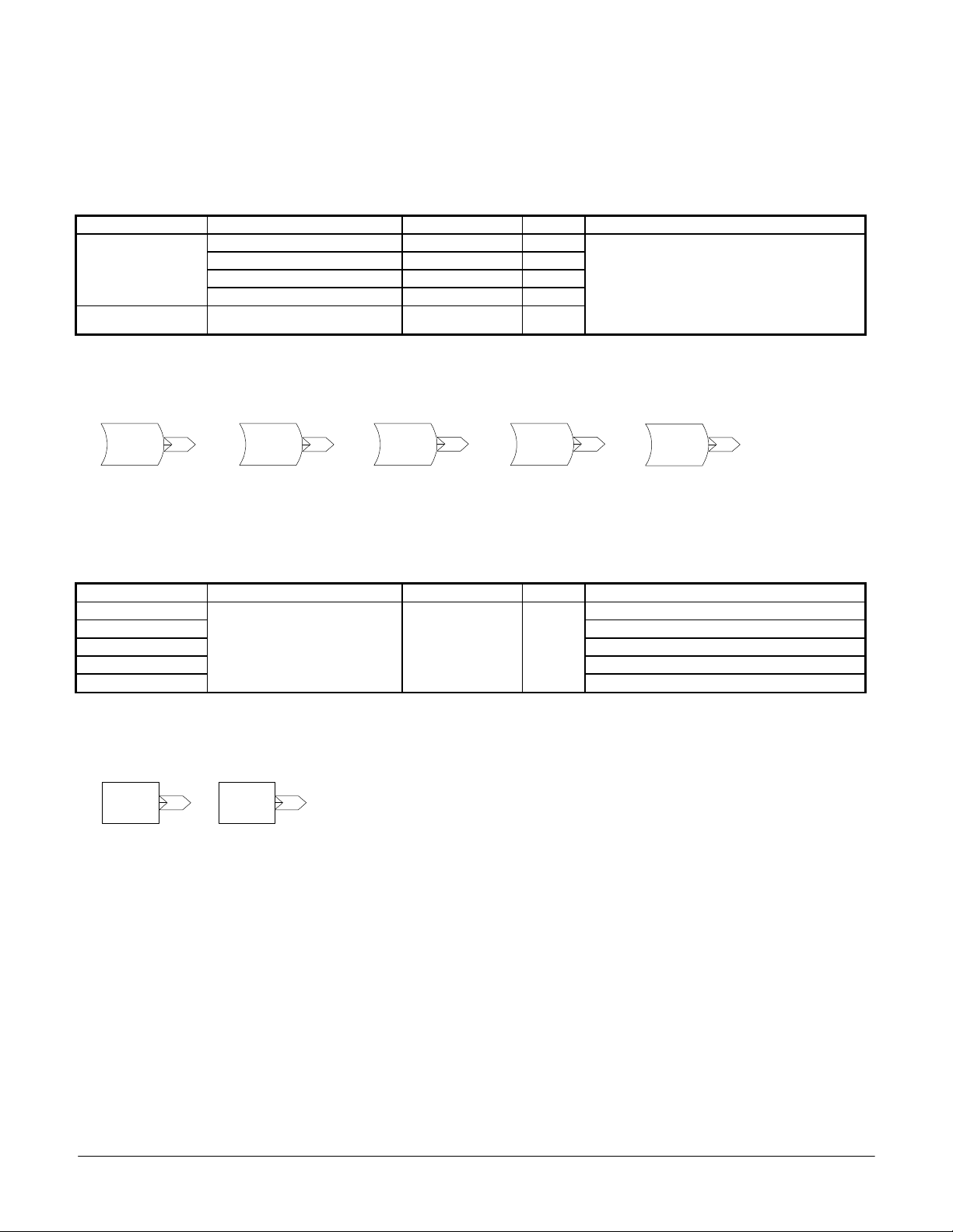
2.2 Operations
Operation function blocks are used to change the data that is input. Some operations may be
needed more than on time in a configuration. This is only possible for the operations that
indicate it. When this is done all inputs of the operation must have the information required
present before the output is executed for each instance. This is important when several
operations are connected together.
2.2.1 Math
Absolute
Value
40
31
Figure 2.2.1
3230
+
3b
3c3a
-
51
5250
X
5b
5c5a
/
Math functions are used to convert numbers as indicated by the function blocks. These
functions may be used more than one time in a configuration. The following equations are used.
Addition: Input 30 + Input 31 = Output 32
Subtraction: Input 3a – Input 3b = Output 3c
It is important to know that the multiplication and division operations are not standard. The
scale function can be used for true multiplication and division.
Change
Sign
41
Date: 07/01/04, Rev: 04-07 Page 13 of 27 TM.G5SW.015
Page 14

Multiplication: (Input 50 X Input 51) / 10000 = Output 52
Division: (Input 5a X 10000) / Input 5b = Output 5c
Absolute Value: |Input 40| = Output 40
Change Sign: Input 41 X –1 = Output 41
2.2.2 Compare
70
Compare
70 <= 71
71
7273False
Figure 2.2.2
74
True
70
Compare
70 = 71
71
7273False
True
70
Compare
70 >= 71
75
71
7273False
True
76
Compare functions compare the value connected to input 70 to the value connected to input 71.
A true operation will output the value connected to input 73. A false operation will output the
value connected to input 72. The output number used determines the compare operation. This
operation may be used more than one time in a configuration. This function is a single function
with three possible outputs.
2.2.4 PID
PID
Figure 2.2.4
2423
The PID function is a PID controller. Input connector 23 to this function must be connected to
the error to correct for. This function can only be used one time in a configuration. It may not
be used with the standard drive PID since many of the same parameters are used for tuning.
B5-01 must be set to disabled.
Function Controls Range Default Setup
B5-02 PID Gain = P Gain 0.00 to 25.00 1.00
B5-03 PID I Time = I Bld Rate 0.00 to 360.00 sec 1.00
PID
B5-04 PID I Limit = I Limit 0.0 to 100.0 % 100.0
B5-05 PID D Time = D Rate 0.00 to 100.0 sec 0.00
B5-06 PID Limit = Output Limit 0.0 to 100.0 % 100.0
B5-01 PID Mode = Disabled
2.2.5 Scale
Scale
Figure 2.2.5
6160
The scale operation functions to scale the value input. This function uses standard
multiplication and division. It can be used for those operations and can be used more than once
in a configuration. The following equation is used;
Date: 07/01/04, Rev: 04-07 Page 14 of 27 TM.G5SW.015
Page 15
output 61 = ((input 60 X P1-08) / P1-09) + P1-10
Function Controls Range Default Setup
P1-08 = Scale Multiplier -9999 to 9999 0
Scale
P1-09 = Scale Divisor -9999 to 9999 0
P1-10 = Scale Bias -9999 to 9999
2.2.6 Center Winder
20
Center
Winder
21
Figure 2.2.6
22
The Center Winder Function calculates and outputs the ratio of line surface speed / winder
motor speed. This ratio can then be divided into the winder’s speed reference to control the
winder motor as the roll diameter increases or decreases. The actual roll diameter can be
calculated by multiplying the ratio by the core diameter. The diameter will be in the same units
as the core diameter. This is a simple center winder function and can be used only one time in
a configuration.
Input connector 20 should connect to the line speed. The line speed must be directly related to
the actual speed of the material being wound. Input connector 21 must be connected to the
winder’s motor speed. When the winder is at core input 20 should equal input 21. The
necessary adjustments must be made to make this a true statement.
The output to this function is filtered to avoid over reacting to sudden short changes in the input
information. Parameter P1-06 controls how fast the drive reacts to the diameter change.
Parameter P1-07 sets the maximum ratio that will be applied to the drive speed and is equal to
maximum roll diameter / core diameter. The ratio calculation will stop at the maximum ratio.
Function Controls Range Default Setup
Center
Winder
P1-06 = Diameter Filter Time 0.1 to 50.0 sec 0.1
P1-07 = Diameter Build Ratio 0.1 to 15.0 12.5 P1-07 = Max Roll Diameter / Core Diameter
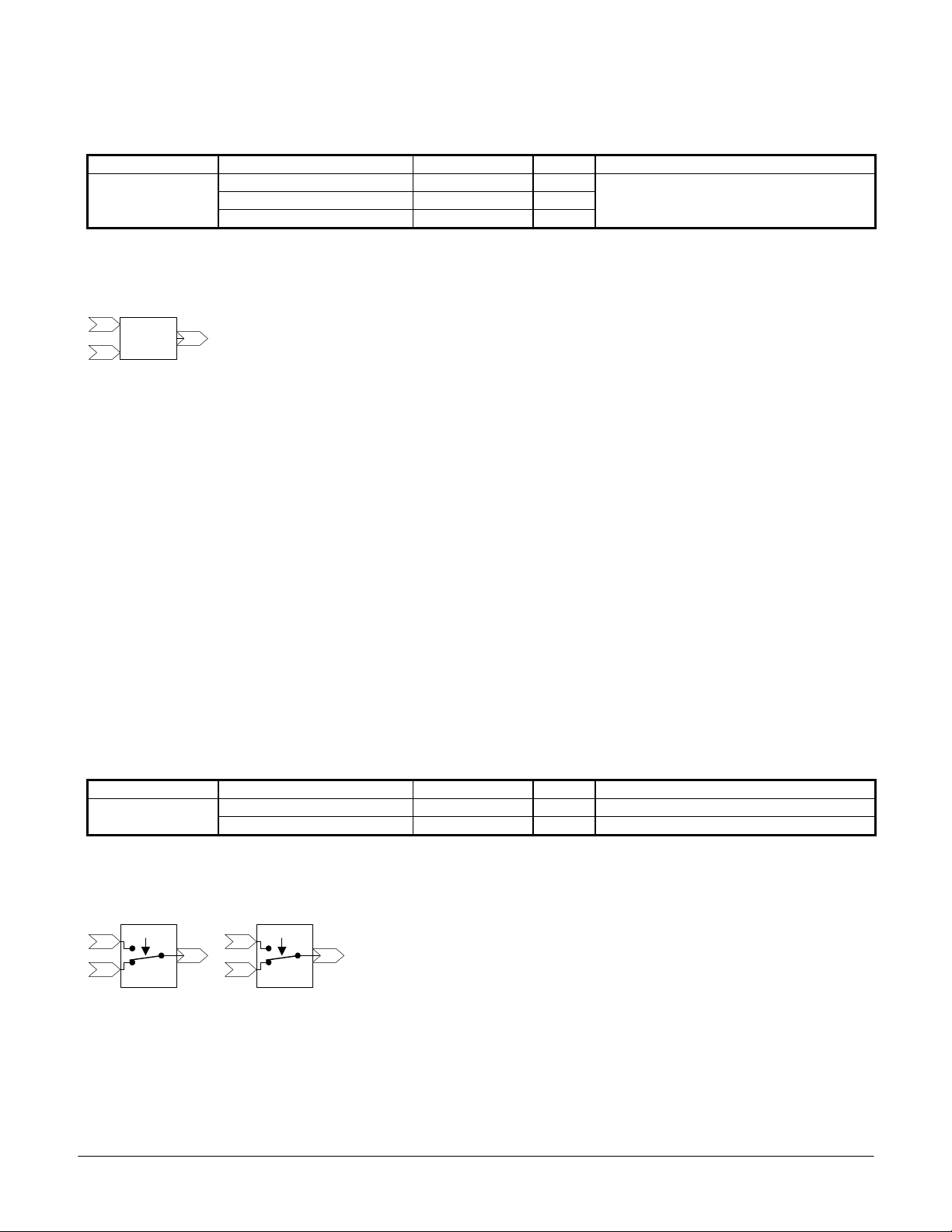
2.2.7 Switch
H1-0? = 80
01
02
Switch 1
Figure 2.2.7
03
04
05
H1-0? = 81
06
Switch 2
The switch function provides a means to switch between two possible inputs via a multi-function
input. Switch 1 connects input 02 to output 03 when the multi-function input is off or not
configured. Switch 1 connects input 01 to output 03 when the configured multi-function input is
turned on. Switch 2 connects input 05 to output 06 when the multi-function input is off or not
Date: 07/01/04, Rev: 04-07 Page 15 of 27 TM.G5SW.015
Page 16

configured. Switch 2 connects input 04 to output 06 when the configured multi-function input is
turned on.
These functions can be used more than one time in a configuration but all instances will switch
when the associated multi-function input is activated.
Function Controls Range Default Setup
Switch 1
Switch 2
Input 01 Normally Open
Input 02 Normally Closed
Input 04 Normally Open
Input 05 Normally Closed
Terminal ? - H1-01 to 06 = 80: Switch 1 DI
Terminal ? - H1-01 to 06 = 81: Switch 2 DI
2.2.8 Number Hold
H1-0? = 85
42
Number
Figure 2.2.8
Hold
43
The number hold function will pass the input value to the output when the associated multifunction input is off. The last value read is held and output to 43 when the multi-function input is
turned on. The hold value is stored in running memory not NVRAM. It will be lost when the
drive is turned off.
Function Controls Range Default Setup
Number Hold
Input 42 connected to output 43
Terminal ? - H1-01 to 06 = 85: Number Hold
2.3 Drive
The Drive functions provide a means to direct information into the drive. Information can be
directed to all drive outputs and monitors.
2.3.1 Drive Speed
Drive
ff
Speed
Figure 2.3.1
The Drive Speed function sends the value input directly to the drive’s speed reference.
2.3.2 Drive Max Torque
Drive
Max
fe
Torque
Figure 2.3.2
Date: 07/01/04, Rev: 04-07 Page 16 of 27 TM.G5SW.015
Page 17

The Drive Maximum Torque function sets or dynamically changes the maximum forward and
reverse torque value used by the drive. This control is only available when A2-01 = 3: flux
vector control mode. The forward and reverse torque values are equal when this function is
used.
2.3.3 Accel / Decel
Accel/
19
Decel
Figure 2.3.3
The Accel / Decel function allows the acceleration and deceleration rates to be dynamically
adjusted. The change may be calculated using the following equations when the input is fixed.
Accel Time = (Input 19 x C1-01) / 10000
Decel Time = (Input 19 x C1-02) / 10000
When the input is 100.00% or 10000 the accel / decel rate will be C1-01 and C1-02.
2.3.4 Drive Output (contact and transistors)
80
Drive
Output 40
Drive
81
Output 41
82
Drive
Output 42
Figure 2.3.4
Drive Output functions provide control to the three multi-function outputs. When the value
connected to the input exceeds the associated P2 parameter level the output will close. It will
open when the input drops below the set level.
Function Information Setup
Contact Output 9 Connects terminal 9 to 10 H2-01 = 40: CONNECTION 80, P2-07: Output 9 Level
Trans Output 25 Sinks terminal 25 to 27 H2-02 = 41: CONNECTION 81, P2-08: Output 25 Level
Trans Output 26 Sinks terminal 26 to 27 H2-03 = 42: CONNECTION 82, P2-09: Output 26 Level
2.3.5 Monitor / Analog Output
U1-50
90
Monitor
95
Figure 2.3.5
U1-55
Monitor
Drive
Analog
Output 50
U1-51
91
Monitor
96
U1-56
Monitor
Drive
Analog
Output 51
U1-52
92
Monitor
U1-57
97
Monitor
U1-53
93
Monitor
U1-58
98
Monitor
U1-54
94
Monitor
U1-59
99
Monitor
Monitor functions provide a means to monitor values within a configuration. They can be used
at any time. Monitor functions do not require setup. The value input into a monitor is divided by
10, to increase the range of the monitor’s display.
Date: 07/01/04, Rev: 04-07 Page 17 of 27 TM.G5SW.015
Page 18

The drive’s analog outputs can be connected to monitor U1-50 and U1-51. This feature must be
setup. The displayed value will be sent to the associated analog output. Setting the connected
analog output gain to 10 will provide the actual value connected to the monitor. The analog
output will operate within the defined range. The gain and bias parameters can be used to scale
the analog output.
Function Information Setup
Monitor 1 (U1-50) H4-01 or H4-04 = 50: Case Monitor 1
Monitor 2 (U1-51)
Information can be passed to analog output terminals 21
and 23
H4-01 or H4-04 = 51: Case Monitor 2
2.3.6 Write Memory
45
Figure 2.3.6
Write
Memory 2
44
Write
Memory 1
Write Memory functions allow values to be stored into memory. The last value input is stored in
running memory not NVRAM. This number can be read using the corresponding Read Memory
function. This function serves as a means to end and store the final value of a function’s output.
This number value can be reintroduce into the control logic where needed by using the Read
Memory function. If the input of the Read Memory function is used before the corresponding
Write Memory function in the configuration sequence the value read will be from the previous
scan. This feature can be used to determine the change from scan to scan.
Date: 07/01/04, Rev: 04-07 Page 18 of 27 TM.G5SW.015
Page 19

3.0 Parameter Changes
3.1 Group A User Parameters
The user parameters are located within the “Initialize” menu selection. When the GPD515/G5
drive has been flashed with this software A2-11 through A2-32 constants are converted to the
parameters used to configure the drive.
3.2 Group b Applications – Function b1 Sequence
Display Constant Setting Display Description
Reference Source b1-01 05 Eliminator Ref Enables the Eliminator Software
3.3 Group H Terminal - Function H1 Digital Inputs
Display Constant Setting Display Description
80 Switch 1 DI Switch function with a common output to a NO and NC input
Terminal 3 Sel
Terminal 4 Sel
Terminal 5 Sel
Terminal 6 Sel
Terminal 7 Sel
Terminal 8 Sel
H1-01
H1-02
H1-03
H1-04
H1-05
H1-06
81 Switch 2 DI Switch function with a common output to a NO and NC input
82 MOP UP Increases the MOP value
83 MOP DOWN Decreases the MOP value
84 MOP RESET Resets the MOP value to the default value set in parameter P2-05
85 Number Hold Holds the last value input until de-activated
86 CASE DI 7 Reserved
87 CASE DI 8 Reserved
3.4 Function H2 Digital Outputs
Display Constant Setting Display Description
Terminal 9 Sel
Terminal 25 Sel
Terminal 26 Sel
H2-01
H2-02
H2-03
40 CONNECTION 80 Switch function with a common output to a NO and NC input
41 CONNECTION 81 Switch function with a common output to a NO and NC input
42 CONNECTION 82 Increases the MOP value
3.5 Function H4 Analog Outputs
Display Constant Setting Display Description
Terminal 21 Sel
Terminal 23 Sel
H4-01
H4-04
50 Case Monitor 1 Links the value in U1-50 to the selected analog output
51 Case Monitor 2 Links the value in U1-51 to the selected analog output
3.6 Group F Options
Constant F1-01, Pulses Per Rev is enabled in all control methods
Date: 07/01/04, Rev: 04-07 Page 19 of 27 TM.G5SW.015
Page 20

4.0 Startup Procedure
1. Develop a configuration list.
2. Connect all external devices.
3. Perform the appropriate procedure for a standard drive startup.
4. Enter the configuration list into the User Parameters starting at A2-11.
5. Set the reference source to “Eliminator Ref” (b1-01 = 5).
6. Test the configuration using care to prevent damage to connected loads.
Date: 07/01/04, Rev: 04-07 Page 20 of 27 TM.G5SW.015
Page 21

5.0 Custom Software Parameters
5.1 New Program Group
Group P
Eliminator Parms
5.2 New Program Function
Function P1
Eliminator P1
Select Eliminator P1 to access parameters P1-01 to P1-10.
Function P2
Eliminator P2
Select Eliminator P2 to access parameters P2-01 to P2-10.
5.3 New Program Parameters
Parameter 1
P1-01 = 0
P1-01 Parameter 1 B B B B
This parameter is provided for user input. Refer to section 2.1.3.
Parameter 2
P1-02 = 0
P1-02 Parameter 2 B B B B
This parameter is provided for user input. Refer to section 2.1.3.
Setting Range: 0 to 65535
Factory Default: 0
Modify During Run: Yes
Modbus Address: 0580H
Setting Range: 0 to 65535
Factory Default: 0
Modify During Run: Yes
Modbus Address: 0581H
Date: 07/01/04, Rev: 04-07 Page 21 of 27 TM.G5SW.015
Page 22

Parameter 3
P1-03 = 0
P1-03 Parameter 3 B B B B
This parameter is provided for user input. Refer to section 2.1.3.
Parameter 4
P1-04 = 0
P1-04 Parameter 4 B B B B
This parameter is provided for user input. Refer to section 2.1.3.
Parameter 5
P1-05 = 0
P1-05 Parameter 5 B B B B
This parameter is provided for user input. Refer to section 2.1.3.
Diam Filter Time
P1-06 = 0.1 sec
P1-06 Diameter Filter Time B B B B
The Diam Filter Time controls the rate of change within the winder filter. Refer to section 2.2.6.
Diam Bld Ratio
P1-07 = 0.1
P1-07 Diameter Build Ratio B B B B
The Diam Build Ratio is the number equal to the ratio of core diameter to maximum roll
diameter. Refer to section 2.2.6.
Example: Core Diameter = 4”
Max Roll Diameter = 48”
Set P1-07 = 48” / 4”‘or 12
Setting Range: 0 to 65535
Factory Default: 0
Modify During Run: Yes
Modbus Address: 0582H
Setting Range: 0 to 65535
Factory Default: 0
Modify During Run: Yes
Modbus Address: 0583H
Setting Range: 0 to 65535
Factory Default: 0
Modify During Run: Yes
Modbus Address: 0584H
Setting Range: 1 to 50 sec
Factory Default: 0.1 sec
Modify During Run: No
Modbus Address: 0585H
Setting Range: 0.1 to 50
Factory Default: 0.1
Modify During Run: No
Modbus Address: 0586H
Date: 07/01/04, Rev: 04-07 Page 22 of 27 TM.G5SW.015
Page 23

Scale Multiplier
P1-08 = 0
P1-08 Scale Multiplier B B B B
The Scale Multiplier number is multiplied times the value of input 60. Refer to section 2.2.5.
Scale Divisor
P1-09 = 0
P1-09 Scale Divisor B B B B
The Scale Divisor is the number divided into the product of the scale multiplication. Refer to
figure 2.2.5.
Scale Bias
P1-10 = 0
P1-10 Scale Bias B B B B
The Scale Bias is the number that will be added to the value of the scale calculation to offset the
value of output 61 up or down. Refer to section 2.2.5.
Max Pulses In
P2-01 = 30720
P2-01 Max Pulses Input B B B B
The Max Pulses In is the number that equals the input pulse rate per second that will result in
100 % inverter output. Refer to section 2.1.4.
Example: 30720 = (1800 rpm X 1024 encoder pulses per rev) / 60 sec (30720 is the default)
MOP Rate / Sec
P2-02 = 0.00 %
P2-02 MOP Rate / Second B B B B
The MOP Rate / Sec sets the rate of MOP change for output 25. This number will be added to
or subtracted from the current value of output 25 when the multi-function input assigned to 82
Setting Range: -9999 to 9999
Factory Default: 0
Modify During Run: Yes
Modbus Address: 0587H
Setting Range: -9999 to 9999
Factory Default: 0
Modify During Run: Yes
Modbus Address: 0588H
Setting Range: -9999 to 9999
Factory Default: 0
Modify During Run: Yes
Modbus Address: 0589H
Setting Range: 0 to 65535
Factory Default: 30720
Modify During Run: Yes
Modbus Address: 0590H
Setting Range: 0.01 to 100.00 %
Factory Default: 0.00 %
Modify During Run: Yes
Modbus Address: 0591H
Date: 07/01/04, Rev: 04-07 Page 23 of 27 TM.G5SW.015
Page 24

MOP UP or 83 MOP DOWN is energized for 5ms. Maintaining this input will result in output 25
changing at this rate per second. Refer to section 2.1.2.
MOP Max Percent
P2-03 = 100 %
P2-03 MOP Maximum Percentage B B B B
The MOP Max Percent sets the maximum MOP value possible for outputs 25 and 26. Refer to
section 2.1.2.
MOP Min Percent
P2-04 = 0 %
P2-04 MOP Minimum Percentage B B B B
The MOP Min Percent sets the minimum MOP value possible for outputs 25 and 26. Refer to
section 2.1.2.
MOP Rst Percent
P2-05 = 0 %
P2-05 MOP Reset Percentage B B B B
The MOP Rst Percent is the value that outputs 25 and 26 are reset to when the multi-function
input assigned to 84 MOP RESET is energized. Refer to section 2.1.2.
MOP Step Rate
P2-06 = 0.00 %
P2-06 MOP Step Rate B B B B
The MOP Step Rate is the number that will be added to or subtracted from the current value of
output 26 when the multi-function input assigned to 82 MOP UP or 83 MOP DOWN is energized
for 5ms. Each transition of either input will result in one step. Refer to section 2.1.2.
Setting Range: 0 to 1000 %
Factory Default: 100 %
Modify During Run: Yes
Modbus Address: 0592H
Setting Range: -1000 to 100 %
Factory Default: 0 %
Modify During Run: Yes
Modbus Address: 0593H
Setting Range: -1000 to 1000 %
Factory Default: 0 %
Modify During Run: Yes
Modbus Address: 0594H
Setting Range: 0.00 to 100.00
Factory Default: 0.00
Modify During Run: Yes
Modbus Address: 0595H
Date: 07/01/04, Rev: 04-07 Page 24 of 27 TM.G5SW.015
Page 25

Out 9 Level
P2-07 = 0
Setting Range: -9999 to 9999
Factory Default: 0.00
Modify During Run: Yes
Modbus Address: 0596H
P2-07 Output 9 level B B B B
The Out 9 Level sets the value that connection 80 must exceed to activate multi-function
selection 40: CONNECTION 80. It is recommended that H2-01 Terminal 9 Sel be setup as 40:
CONNECTION 80. This value is multiplied by 10 within the software. Refer to section 2.3.4
Out 25 Level
P2-08 = 0
Setting Range: -9999 to 9999
Factory Default: 0
Modify During Run: Yes
Modbus Address: 0597H
P2-08 Output 25 Level B B B B
The Out 25 Level sets the value that connection 81 must exceed to close multi-function
selection 41: CONNECTION 81. It is recommended that H2-02 Terminal 25 Sel be setup as
41: CONNECTION 81. This value is multiplied by 10 within the software. Refer to section 2.3.4
Setting Range: -9999 to 9999
Out 26 Level
P2-09 = 0
Factory Default: 0
Modify During Run: Yes
Modbus Address: 0598H
P2-09 Output 26 Level B B B B
The Out 26 Level (x10) sets the value that connection 82 must exceed to activate multi-function
selection 42: CONNECTION 82. It is recommended that H2-03 Terminal 26 Sel be setup as
42: CONNECTION 82. This value is multiplied by 10 within the software. Refer to section 2.3.4.
Max Torque Ref
P2-10 = 0.00 %
Setting Range: 0.00 to 300.00 %
Factory Default: 0.00 %
Modify During Run: Yes
Modbus Address: 0599H
P2-10 Maximum Torque Reference B B B B
The Max Torque Ref value is the limit applied to input ‘fe’ of the drive maximum torque function.
This is a bipolar limit and limits the torque output of the drive to this value. The values set in the
L7 torque limiting constants remain in effect. Refer to section 2.3.2.
Date: 07/01/04, Rev: 04-07 Page 25 of 27 TM.G5SW.015
Page 26

6.0 New Monitors
Monitor 1
U1-50 0.0
Monitor 1 will display the value / 10 of the output connected to input 90. When this monitor is
used with the analog output function the displayed number is output.
Monitor 2
U1-51 0.0
Monitor 2 will display the value / 10 of the output connected to input 91. When this monitor is
used with the analog output function the displayed number is output.
Monitor 3
U1-52 0.0
Monitor 3 will display the value / 10 of the output connected to input 92.
Range: -3276 to 3276.7 (x10)
Modbus Address: 00d0H
Range: -3276 to 3276.7 (x10)
Modbus Address: 00d1H
Range: -3276 to 3276.7 (x10)
Modbus Address: 00d2H
Monitor 4
U1-53 0.0
Monitor 4 will display the value / 10 of the output connected to input 93.
Monitor 5
U1-54 0.0
Monitor 5 will display the value / 10 of the output connected to input 94.
Monitor 6
U1-55 0.0
Monitor 6 will display the value / 10 of the output connected to input 95.
Range: -3276 to 3276.7 (x10)
Modbus Address: 00d3H
Range: -3276 to 3276.7 (x10)
Modbus Address: 00d4H
Range: -3276 to 3276.7 (x10)
Modbus Address: 00d5H
Date: 07/01/04, Rev: 04-07 Page 26 of 27 TM.G5SW.015
Page 27

Monitor 7
U1-56 0.0
Monitor 7 will display the value / 10 of the output connected to input 96.
Monitor 8
U1-57 0.0
Monitor 8 will display the value / 10 of the output connected to input 97.
Monitor 9
U1-58 0.0
Monitor 9 will display the value / 10 of the output connected to input 98.
Monitor 10
U1-59 0.0
Monitor 10 will display the value / 10 of the output connected to input 99.
Range: -3276 to 3276.7 (x10)
Modbus Address: 00d6H
Range: -3276 to 3276.7 (x10)
Modbus Address: 00d7H
Range: -3276 to 3276.7 (x10)
Modbus Address: 00d8H
Range: -3276 to 3276.7 (x10)
Modbus Address: 00d9H
Date: 07/01/04, Rev: 04-07 Page 27 of 27 TM.G5SW.015
 Loading...