

Page 1

Electronic Lineshaft with Alignment
GPD515/G5 Software Option (VSG114713E)
Part Number: CIMR-G5MXXXXXF-046
(1)
A Yaskawa GPD515/G5 flashed with this software has the ability to electronically emulate a lineshaft connection
between 2 or more independently driven devices. In this system there will be a master device and one or more
slave drives. The slaves will follow the master device and can be automatically aligned to it by using the
alignment feature. Once aligned the relationship between the leading master device and the following slave
drives will be maintained. The gearing feature allows the slaves drives to follow the master device at a definable
ratio.
This system requires supplying the slave drive with a line driver quadrature feedback from the device to be
followed. Any electronic device that is capable of supplying the following drive with the proper signal can be used
as the master signal. The following drive will follow the master signal pulse for pulse after applying the ratio in
either direction. The following drive must be operated using closed loop or flux vector control and therefore must
have an encoder coupled to the motor.
The typical application will have a master drive and a slave drive. The equipment being driven requires two
mechanically isolated and motor driven moving parts to maintain a constant position relationship to within a few
encoder counts. The position of the moving part driven by the slave motor requires alignment to the position of
the master device.
The master drive can be operated in any control mode but master device feedback connected to the slave drive is
required. The feedback or master signal controls the follower drive. The follower drive monitors the master
signal and compares it to the feedback from the slave motor’s encoder. The follower will then compensate for
any position errors resulting by adjusting the output frequency of the slave drive. This results in near perfect
alignment between the master device and slave device. There is no accumulation of position error, so alignment
will always be maintained within a few pulses.
The slave drive has an automatic alignment feature with this software. This feature provides a means of aligning
the follower encoder to the master signal. This is accomplished by using two switches connected to the trigger
inputs of the slave drive. One switch is used to indicate the position of the master. The other switch is used to
indicate the position of the follower. When the alignment feature is active, advancing or retarding the slave motor
corrects the difference between when these switches are activated. When both encoders are activated at the
same time the master and follower are aligned. An offset feature is provided enabling fine adjustment for switch
misalignment.
This software provides a trim advance and retard input to adjust the following drive in respect to the to the master.
Adjustments can be made while running. This adjustment will change the position or phase relationship between
the drives.
When the master signal is from another GPD515/G5 it is not necessary for it to be running lineshaft software. All
follower or slave GPD515/G5 drives must be running lineshaft software.
Date: 07-01-04, Rev: 04-07 Page 1 of 15 TM.G5SW.046
Page 2

Electronic Lineshaft with Alignment
Features:
Disable Lineshaft Input – Disables the lineshaft software placing the drive back into standard control
Advance (Trim) Input – Advances the alignment position of the slave drive at a settable rate
Retard (Trim) Input – Retards the alignment position of the slave drive at a settable rate
Slave Trigger Input – Indicates the position of the slave drive when activated
Master Trigger Input – Indicates the position of the master drive when activated
Align Slave Input – Enables the automatic alignment feature
Aligned Output – Indicates the alignment procedure was performed and the following drive did align
Alignment Checking – Monitors the difference between the trigger inputs with the result controlling an output
Alignment Fault – Monitors the travel during alignment and faults the drive when the limit is exceeded
Following Alarm – Monitors the following error and provides a selectable result when it exceeds the limit
Gear Ratio – Adjust the ratio of the following drive in respect to the master
Monitors – Displays useful information to indicate how close the follower is following
The disable lineshaft input provides a means to operate the drive independent from the master drive. This feature
can be selected at any time and disables all lineshaft features when active. The position relationship between the
master and the slave drive will be lost when this input is activated. The slave drive will maintain the current
position with the master when the lineshaft disable input is deactivated.
The trim controls provide a means to adjust the position relationship between the master and the slave drives.
The trim rate is settable. The slave position can be advanced or retarded in relation to the master drive when the
slave’s run input is on. The trim can function if the run input is on.
The align slave, master and slave trigger inputs are required to perform an alignment. The alignment procedure
can be used to align the slave to the master using fixed trigger positions. This process does not control the
master drive. All correction is made by the slave drive. The amount of the correction is controlled by the
quadrature counts that are accumulated from the time when the first or leading trigger starts the process and
continues until the trailing trigger stops it. The correction will be made as soon as the trailing trigger input
becomes active. This process was intended to be performed at lower frequencies but will function if the triggers
provide a minimum of a 5 millisecond signal.
The alignment check is provided to indicate whether the trigger inputs are activated within a settable quadrature
count range. An alignment check output will be on when the triggers are within the defined range and will go off
when the range is exceeded. This output will only change after the trailing trigger has activated. This check is
always active in lineshaft mode.
The following alarm monitors the quadrature error count that exists between the master and the slave drive. If the
count exceeds the settable range a selectable action will occur.
The gear ratio provides a means to apply a ratio between the master device and the slave drive. This may be
used to correct for errors in drivetrain ratios or to apply a required ratio between the drives.
The monitors provided allow monitoring of how well the slave drive is following the master signal. The master
signal can also be monitored.
Date: 07-01-04, Rev: 04-07 Page 2 of 15 TM.G5SW.046
Page 3

1.1 Sample Application
Electronic Lineshaft with Alignment
Gear
Slave
Box
d
e
n
g
i
l
A
Master
Motor
Slave Trigger Switch
Motor
Slave Motor
Slave Encoder
PG-W2
GPD
515
Master Motor
Master Encoder
Master Trigger Switch
PG-X2
GPD
515
This example shows two pusher chains. Each chain is mechanically isolated from the other. The master
and slave trigger switches are placed in line providing an alignment position for the pushers. The pusher’s
leading edge will activate the switches as they pass.
When this line starts alignment is necessary. The “Align Slave” input must be activated and maintained to
cause the alignment feature to operate. The slave drive will align itself after the trailing pusher has
triggered. The “Aligned” output indicates that the alignment procedure was successful and that the “Align
Slave” input may be removed. If this input is not removed alignment will occur each time a pusher passes a
trigger switch. The pushers will be aligned to the associated trigger switch position.
The lineshaft software will maintain the follower’s position in respect to the master. The follower position is
monitored and if it exceeds the users set value a following fault or alarm will result. The alignment check
will also monitor the quadrature counts between the triggers. An “Alignment Check” output will remain on if
the check was within the set range.
Date: 07-01-04, Rev: 04-07 Page 3 of 15 TM.G5SW.046
Page 4

Electronic Lineshaft with Alignment
1.2 Example Configuration Diagram
to the 1
OR
OR
OR
OR
Master Source Signal
st
Slave GPD515 Drive
Master Source Signal
nd
Slave GPD515 Drive
to the 2
Master Source Signal
to the 3rd Slave GPD515 Drive
Master Source Option 1
Pulse
Generator
+A Pulse
-A Pulse
+B Pulse
-B Pulse
Master Source Option 2
Encoder
Master Source Option 3
Motor
Encoder
1.2 Example Wiring Diagram
Master Drive
T1
T2
T3
MGL
Red 5-15VDC
1
Black Common
2
3
Blue +A
4
Gray -A
5
Green +B
6
Yellow -B
7
8
9
Blue +A
1
Gray -A
2
Green +B
3
Yellow -B
TA2 TA1
4
PG-X2 PCB Option
5
6
TA3
Run
Speed Ref
L1
L2
GPD515
L3
1 FWD Run
2 REV Run
3 EXT Fault
4 Fault Reset
5 Definable
6 Definable
7 Definable
8 Definable
11 Common
12 GND
13 Input 0-10V
14 Input 4-20mA
15 Supply +15V@20mA
16 Input 0-10V
17 Supply Common
33 Supply -15V@20mA
9
10
18
19
20
25
26
27
23 Analog Output +/- 10 VDC
24 Analog Output +/- 10 VDC
25 Analog Output Common
IM
Motor
Shield
Master Source Option 4
Encoder
encoder
PG-X2
GPD
515
Any Software
Master
Motor
Encoder
Enable / Run
Disable
S Align Switch
M Align Switch
Alignment Sw
PG-W2
GPD
515
G114712
Software
Slave 1
Motor
Slave Drive
L1
GPD515
L2
G11471x
L3
1 FWD Run
2 REV Run
3 EXT Fault
4 Fault Reset
5 DisableLineshaft
6 Slave Trigger
7 Master Trigger
8 Align Slave
11 Common
12 GND
13 Input 0-10V
14 Input 4-20mA
15 Supply +15V@20mA
16 Input 0-10V
17 Supply Common
33 Supply -15V@20mA
9
10
18
19
20
25
26
27
23 Analog Output +/- 10 VDC
24 Analog Output +/- 10 VDC
25 Analog Output Common
PG-W2
GPD
515
G114712
Software
Slave 2
Motor
Encoder
T1
T2
T3
MGL
Red 5-15VDC
1
Black Common
2
Blue +A
3
Gray -A
4
Green +B
5
Yellow -B
6
7
8
9
Blue +A
10
Gray -A
11
Green +B
12
Yellow -B
13
14
15
16
+A
17
PG-W2 PCB Option
-A
18
+B
19
-B
20
21
22
Shield
23
24
To Next Drive
IM
Motor
encoder
Date: 07-01-04, Rev: 04-07 Page 4 of 15 TM.G5SW.046
Page 5

Electronic Lineshaft with Alignment
1.3 PG-W2 Terminal Description and Wiring Notes
Refer to the GPD515/G5 User’s Manual for additional information regarding encoder feedback option cards.
PG-W2
Terminal #
1 IP12 +12V supply to power encoder
2 IG12
3 +A
4 -A
5 +B
6 -B
10 +A
11 -A
12 +B
13 -B
17 +A
18 -A
19 +B
20 -B
For proper lineshaft operation the following conditions must be met:
1) A PG-W2 encoder feedback card must be installed in the follower VFD(s).
2) The pulse reference from the master device must be quadrature, differential line driver type.
3) Encoder feedback from the follower motor must be quadrature, differential line driver type.
4) When the master operates in its normal, forward direction, monitor U1-50 of the follower should display a
positive value. If it does not, it may be necessary to reverse the channel 2 pulse input A wires at
terminals 10 and 11 of the follower’s PG-W2.
5) If the follower’s U1-50 display is positive, when the drive is commanded to run via input to terminal #1, the
motor should rotate in the proper direction and the follower’s U1-05 monitor should display a positive value. If
the motor direction is incorrect, it may be necessary to reverse any two of the motor leads on the VFD output.
If the motor fails to rotate, or is unstable, it may be necessary to reverse the channel 1 pulse input A wires at
terminals 3 and 4 of the PG-W2.
6) Do not use parameter F1-05 to change encoder phasing in this software. Please swap encoder
signals A+ and A- instead.
1.4 Alignment Operation Description
The alignment operation performed by the follower drive requires three external inputs. The “Align Slave” input
enables and disables the alignment feature. The “Master Trigger” input indicates the master drive is at the
aligned position. The “Slave Trigger” input indicates that the slave drive is at the aligned position. The aligned
position is where both trigger switches are activated at the same time.
When the “Align Slave” input is activated the slave drive will monitor the trigger inputs. The slave drive will
accumulate the error count that separates the leading edges of the trigger inputs. When aligned both triggers are
simultaneous. When not aligned the leading trigger will start an error count. The following trigger will stop the
error count and the error will be corrected by advancing or retarding the slave drive at a maximum frequency of 4
Hz. The correction will occur when the leading edge of the following trigger is activated.
The recommended speed range for alignment is between 6 to 12Hz. Alignment can be performed at higher
speeds. The trigger inputs require a minimum signal of 5 milliseconds. If the alignment speed is below 4 Hz the
slave drive may run in the reverse direction to retard.
Parameter P1-02: “Align Offset” has been provided to adjust for misalignment of the trigger switches. The
adjustment allows for + / - 9999 quadrature encoder counts or approximately 2.5 motor revolutions when using a
Designation Function Remarks
Power Supply
Follower Motor
Feedback
Master
Device
Signal
Pulse Output
(Mirrors Channel 2)
0V, Common for 12V power supply
Channel 1, Pulse Input A
Channel 1, Pulse Input B
Channel 2, Pulse Input A
Channel 2, Pulse Input B
Encoder 2, Pulse Output, Channel A (5V pk)
Encoder 2, Pulse Output, Channel B (5V pk)
Date: 07-01-04, Rev: 04-07 Page 5 of 15 TM.G5SW.046
Page 6

Electronic Lineshaft with Alignment
1024 pulse encoder with a 4096 quadrature encoder count. The sign is determined in respect to the master
trigger switch.
Alignment is when both master and slave triggers are activated simultaneously. If the trigger switches are not
aligned properly the align offset can be used to correct the error. A negative offset indicates the slave drive
needs to retard. A positive offset indicates the slave drive needs to advance.
A minus offset value is indicative of the slave trigger occurring before the master resulting in the need to retard
the drive by the negative offset count set in P1-02. A positive value indicates the slave trigger occurs after the
master resulting in the need to advance the drive.
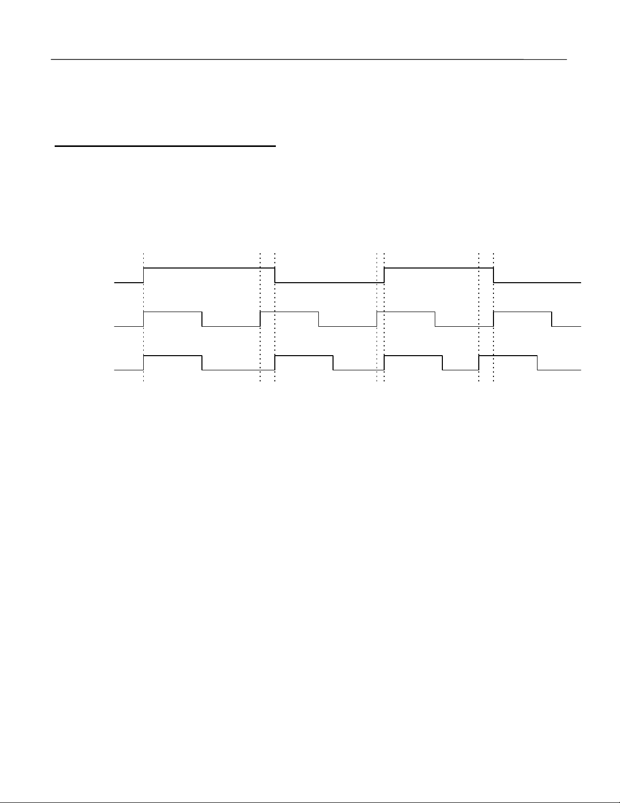
Alignment Timing Chart
Slave Run
Input Term #1
Master Run
Input Term #1
Aligned
Output
Master Trigger
Input
Slave Trigger
Input
Align Slave
Input
Alignment
Error
Slave Freq
Output
Master Freq
Output
Chart Explanation:
The slave drive is set to run. The master driver is set to run. The slave follows the master drive. The align slave
input is activated and maintained. Both master and slave triggers are activated simultaneously. No alignment
error is accumulated and no correction in alignment is made.
The master trigger is activated. The alignment error begins to accumulate. The slave trigger is activated. The
alignment error accumulation stops. The alignment error is corrected by accelerating the slave drive because the
master was leading the slave. Both triggers are deactivated.
The slave trigger is activated. The alignment error begins to accumulate. The master trigger is activated. The
alignment error accumulation stops. The alignment error is corrected by decelerating the slave drive because the
slave was leading the master. Both triggers are deactivated.
The “Aligned Output” will activate when the slave drive has corrected the position error to within 50 encoder
counts. It will not reset until the “Slave Run” input has been removed or the “Align Slave” input has been removed
and reactivated.
Date: 07-01-04, Rev: 04-07 Page 6 of 15 TM.G5SW.046
Page 7
Electronic Lineshaft with Alignment
When the run signal is removed from the master drive the slave drive will follow the master to a stop.
When the alignment process has completed the “Align Slave” input may be removed to prevent continuous
alignment. The “Aligned Output” will not reset until the “Align Slave” input has been removed and reactivated.
1.4 Alignment Check Description
When operating in lineshaft mode an alignment check is performed. This check monitors the difference in
quadrature counts that separates the trigger inputs. The alignment offset is factored into the calculation. If the
error count exceeds the value set in P1-10 the alignment check output will be off. This output will only change
states after an alignment check. When the alignment check output is on it indicates that the error count between
the master and slave trigger inputs was less than the value set in P1-10 when last checked.
Alignment Checking Chart
Alignment
Check Output
Master Trigger
Input
Slave Trigger
Input
{
Exceeds P1-10: Alignment Check Exceeds P1-10: Alignment Check
{
Within P1-10: Alignment Check
{
Date: 07-01-04, Rev: 04-07 Page 7 of 15 TM.G5SW.046
Page 8
Electronic Lineshaft with Alignment
2.0 I/O Definitions
2.1 New Multi-Function Digital Input Settings
For constants H1-01 through H1-06.
Setting Display Description
80 Disable LineShft Closed: Line Shaft Mode is disabled
83 Advance Slave Closed: Slave drive will increase speed without accumulating error
84 Retard Slave Closed: Slave drive will decrease speed without accumulating error
85 Slave Trigger Closed: The slave encoder has achieved the alignment position
86 Master Trigger Closed: The master encoder has achieved the alignment position
87 Align Slave Closed: The error count between the triggers will be corrected
2.2 New Multi-Function Digital Output Settings
For constants H2-01 through H2-03.
Setting Display Description
40 Alignment Check On = The alignment has check was within the set range
42 Aligned On = The alignment function was performed successfully
3.0 Configuration Notes
This software document is only a supplement to the GPD515/G5 Series instruction manual. All parameters and
features not mentioned in this document have not changed.
3.1 Changed Factory Defaults of Standard Parameters
None
3.2 Minimum Programming Requirements for “Line Shaft” Operation
1. The follower VFD must be programmed for the Flux Vector control method, A1-02 = 3.
2. The follower’s run and reference sources, B1-01 and B1-02, must be set to 5:Line Shaft.
Date: 07-01-04, Rev: 04-07 Page 8 of 15 TM.G5SW.046
Page 9

Electronic Lineshaft with Alignment
4.0 Custom Software Parameters
4.1 New Program Group
Group P
Elect Line Shaft
4.2 New Program Function
Function P1
Line Shaft Data
Function P2
Line Shaft Data
4.3 New Program Parameters
Master PPR
P1-01= 1024
P1-01 Master PPR
The number of output pulses per revolution from the master encoder. (not quadrature)
Align Offset
P1-02= 0
P1-02 Align Offset
The “Aligned Offset” is provided to correct for the misalignment of the trigger inputs preventing the need to do fine
mechanical adjustments. This value may be used as a fine tuning feature to align the slave to the master making
setup much easier. The range provides for approximately 2.5 motor revolution.
Setting Range: 0 to 10000
Factory Default: 1024
MODBUS Address: 0580H
B B B B
Setting Range: + / - 9999
Factory Default: 0
MODBUS Address: 0581H
B B B B
Date: 07-01-04, Rev: 04-07 Page 9 of 15 TM.G5SW.046
Page 10

Electronic Lineshaft with Alignment
Over Travel Lmt
P1-03= 0
P1-03 Over Travel Lmt
The “Over Travel Limit” is used during the alignment procedure and is the maximum error count permitted. The
error count is the number of encoder pulses that occurs between trigger inputs. When master and slave are
aligned the error count will be 0. If this value is exceeded an “Align_Flt” will occur and stop the drive.
Position P gain
P1-04= 10.00
P1-04 Position Error Proportional Gain
The ‘proportional gain’ adjusts the follower’s speed reference to compensate for any position error between the
master and slave. The proportional function increases speed compensation based on the magnitude of the
position error. Increasing the proportional gain makes the follower more responsive to position errors.
The maximum correction factor added by P1-04 defaults at +/- 2.000 Hz. This limit can be adjusted using P2-04
P Limit.
Setting Range: 1 to 99999
Factory Default: 0
MODBUS Address: 0582H
B B B B
Setting Range: 0.00 to 100.00
Factory Default: 10.00
MODBUS Address: 0583H
B B B B
Position I time
P1-05= 0.10 Sec
P1-05 Position Error Integral Time
The ‘integral time’ adjusts the follower’s speed reference to compensate for any position error between the
master and slave. The integral function increases speed compensation based on the amount of time a given
error exists. Decreasing the integral time makes the follower more responsive to position errors.
The maximum correction factor added by P1-05 defaults at +/- 2.000 Hz. This limit can be adjusted using P2-05 I
Limit.
TrimRate ct/10ms
P1-06= 20
P1-06 Rate of Advance/Retard at Digital Input
The follower can be advanced or retarded at the rate of P1-06 counts every 10 mSec, whenever a multifunction
digital input programmed to 83 (advance) or 84 (retard) is closed. When the digital input is removed, the follower
will maintain synchronization with the master, at the follower’s advanced (retarded) position. This feature also
functions when a gear ratio is used.
Follw.trip cnts
Setting Range: 0.00 to 100.00 Sec
Factory Default: 0.10 Sec
MODBUS Address: 0584H
B B B B
Setting Range: 0 to 1000
Factory Default: 20
MODBUS Address: 0585H
B B B B
Setting Range: 0 to 32767
Factory Default: 4096
MODBUS Address: 0586H
Date: 07-01-04, Rev: 04-07 Page 10 of 15 TM.G5SW.046
Page 11

Electronic Lineshaft with Alignment
P1-07= 4096
P1-07 Follower Trip Counts
If the position error between the master and the follower exceeds the P1-07 setting, the follower will respond
based on the P1-08 setting.
Trip Reaction
P1-08= 2
Setting Range: 0 to 2
Factory Default: 2
MODBUS Address: 0587H
P1-08 Trip Reaction
If the position error between the master and the follower exceeds the P1-07 setting, the follower responds as
selected below.
Setting Description
0 The follower continues operation without trip annunciation
1 The follower continues operation while displaying FOL_ALM
2 The follower faults, coasting to a stop, and displays FOL_FLT
Resync Property
P1-09= 1
Setting Range: 0 to 1
Factory Default: 1
MODBUS Address: 0588H
P1-09 Resync Property
The follower can be configured to respond to, or ignore, position errors when it is under power but not running.
With a setting of 0, the follower will monitor the position of both the master and the follower. If a position error
develops, via movement of the master or follower shaft, at the initiation of a run command the follower will
advance or retard accordingly, to cancel the position error. With a setting of 1, the follower sets the position error
to zero, ignoring any movement of the master or follower until a ‘run’ command is initiated.
Setting Description
0 Accumulates position error when not running. Corrects error at ‘run’
1 Holds position error at zero when not running.
Alignment Check
P1-10 = 100
Setting Range: 0 to 32767
Factory Default: 100
MODBUS Address: 0589H
P1-10 Alignment Check Counts
The alignment check counts is the number of error counts that are acceptable between the position trigger inputs.
When the error count is within this range the alignment checked output will activate. The output will only change
states after a check has been performed.
B B B B
B B B B
B B B B
B B B B
Date: 07-01-04, Rev: 04-07 Page 11 of 15 TM.G5SW.046
Page 12

Electronic Lineshaft with Alignment
Ratio Numerator
P2-01=1000
P2-01 Ratio Numerator
The ratio numerator is multiplied by the encoder feedback from the master and then is divided by the ratio
denominator. This provides the ability to use a gear ratio between the master and the slave. See P2-02.
Ratio Demomin
P2-02=1000
P2-02 Ratio Denominator
The ratio denominator is divided into the product of the ratio numerator and the encoder feedback from the
master.
Example:
Slave Speed = (Master Encoder Feedback x P2-01) / P1-02
Feedback = 10 Hz , P1-01 = 1000, P2-02 = 250
Slave Speed = (10 Hz x 1000) / 250 or 40 Hz
Feedback = 10 Hz , P1-01 = 250, P2-02 = 1000
Slave Speed = (10 Hz x 250) / 1000 or 2.5 Hz
The position relationship between the master and the slave is maintained just as if a lineshaft went through a
gearbox with the same ratio. If the ratio is unknown it may be determined by counting the motor revolutions
required to make a complete machine cycle of both the master and slave. Convert the counts into a four digit
number by multiplying or dividing both by the same number. Set P1-01 to the slave count and set P1-02 to the
master count.
Example:
Master = 10 revs., Slave = 2.5 revs., Multiply both by 100
Master = 1000, Slave = 250
P1-01 = 250, P1-02 = 1000
P Limit
P2-04=2.000 HZ
P2-04 Proportional Limit
This parameter limits the proportional part of the position regulator.
Setting Range: 0 to 9999
Factory Default: 1000
MODBUS Address: 0590H
Q Q Q Q
Setting Range: 0 to 9999
Factory Default: 1000
MODBUS Address: 0591H
Q Q Q Q
Setting Range: 0.000 to 20.000
Factory Default: 2000
MODBUS Address: 0593H
Q Q Q Q
Date: 07-01-04, Rev: 04-07 Page 12 of 15 TM.G5SW.046
Page 13
Electronic Lineshaft with Alignment
I Limit
P2-05=2.000 HZ
P2-05 Integral Limit
This parameter limits the integral part of the position regulator. This parameter should be increased when the
drive will not stay shaft-locked under heavy loads or at high speeds (above base speed). Too high of a setting
will result in instability or overshoot.
D Time
P2-06 = 0.00 sec
P2-06 Derivative Time
This parameter provides control of the derivative function of the PID speed control loop. Setting this value to zero
will remove any affect that it may have. The derivative provides a means to stabilize the position error if it is
oscillating between plus and minus. Setting this value to high will cause instability.
Setting Range: 0.000 to 20.000
Factory Default: 2000
MODBUS Address: 0594H
Q Q Q Q
Setting Range: 0.00 to 100.00
Factory Default: 0.00
MODBUS Address: 0595H
Q Q Q Q
5.0 New Monitors
Master Encoder
U1-50= 0.00 kHZ
U1-50 Master Encoder
Displays the pulse frequency of the master encoder.
Slave Reference
U1-51= 0.0 HZ
U1-51 Slave Reference
Displays the frequency reference of the follower drive prior to ratio adjustments. The follower will not exceed its
maximum output frequency based on E1-04 and D2-01.
Range: 0.00 to 327.67 kHz
MODBUS Address: 00D0H
Q Q Q Q
Range: -999.9 to 3276.7 Hz
MODBUS Address: 00D1H
Q Q Q Q
Date: 07-01-04, Rev: 04-07 Page 13 of 15 TM.G5SW.046
Page 14

Electronic Lineshaft with Alignment
Position err cts
U1-53= 0
U1-53 Position Error in Counts
Displays the error, in encoder counts, between the master and follower.
Posit.P Gain
U1-54= 0.000 HZ
U1-54 P-Gain Correction of Position Error
Displays the frequency adjustment to the follower’s speed reference, based on the proportional gain setting.
Posit.I Gain
U1-55= 0.000 HZ
U1-55 I-Gain Correction of Position Error
Displays the frequency adjustment to the follower’s speed reference, based on the integral time setting.
LineShaft Speed
U1-56= 0.00 HZ
U1-56 Line Shaft Speed Reference Output
The follower’s final speed reference derived from the “line shaft” algorithm. Includes the initial reference from the
master plus compensation due to gearing and proportion/integral adjustments.
Range: -9999 to 32767
MODBUS Address: 00D3H
Q Q Q Q
Range: -2.000 to 2.000 Hz
MODBUS Address: 00D4H
Q Q Q Q
Range: -2.000 to 2.000 Hz
MODBUS Address: 00D5H
Q Q Q Q
Range: -99.99 to 327.67 Hz
MODBUS Address: 00D6H
Q Q Q Q
Date: 07-01-04, Rev: 04-07 Page 14 of 15 TM.G5SW.046
Page 15
Electronic Lineshaft with Alignment
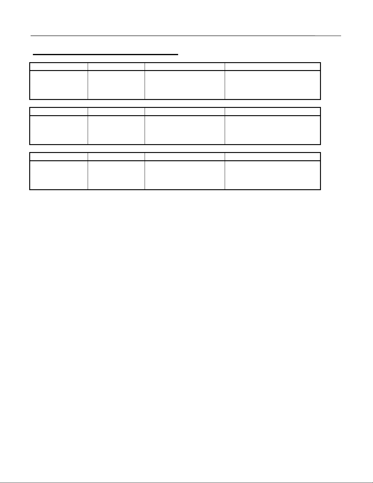
6.0 New Alarm and Fault Codes
Alarm Display Name Description Corrective Action
FOL_ALM
Following Alarm
Fault Display Name Description Corrective Action
FOL_FLT
Following Fault
Fault Display Name Description Corrective Action
ALIGN_FLT
Align Fault
Following Alarm
Following Error
Alignment Error
The position error between
the master and slave
exceeded the allowable
amount. (P1-07 – P1-08)
The position error between
the master and slave
exceeded the allowable
amount. (P1-07 – P1-08)
The error count between
the master and slave
exceeded the allowable
amount. (P1-03)
Check for physical obstruction of
slave motion.
Check for physical obstruction of
slave motion.
Check the trigger input switches.
Date: 07-01-04, Rev: 04-07 Page 15 of 15 TM.G5SW.046
 Loading...