

Yard-Man 950, 970, 960, 990 Owner's Manual

Owner’s Manual
¨SET-UP ¨OPERATION ¨MAINTENANCE
IMPORTANT: Read Safety Rules and Instructions Carefully
PRINTED IN CANADA OG-3105

CALLING CUSTOMER SUPPORT
• LOCATE YOUR MODEL NUMBER AND SE RIAL NUMBER which ap pears on your unit and
record the in formation in the space pro vided be low.
IM POR TANT: You must have these num bers, along with the date and proof of
purchase to re ceive war ranty or ser vice.
• If you are hav ing difficulty as sembling this prod uct or if you have any ques tions re garding the
controls, operation or main tenance of this unit, please call the Cus tomer Sup port De partment.
• Customer Sup port can be reached by di aling: 1-800-668-1238
• Please have your model num ber and se rial num ber ready when you call.
NOTE: Al though both num bers are im portant, you will be asked to en ter only your
serial num ber be fore your call can be pro cessed.
This is where your model num ber will be,
record model number here:
This is where your se rial num ber will be,
re cord se rial num ber here:
TABLE OF CON TENTS
CALLING CUS TOMER SUPPORT .............................................2
TABLE OF CON TENTS .....................................................2
IM POR TANT SAFE OP ER A TION PRAC TICES ....................................3
SLOPE GAUGE...........................................................6
SET-UP IN STRUC TIONS ....................................................7
CON TROLS .............................................................8
OP ER A TION.............................................................9
AD JUST MENT ..........................................................12
LU BRI CA TION ..........................................................13
MAIN TE NANCE..........................................................13
OFF SEA SON STOR AGE IN STRUC TIONS......................................17
RE PLACE MENT PARTS/PIÈCES DÉTACHÉES...................................18
WAR RANTY: ............................................................29
TROU BLE SHOOTING ....................................................30
For more de tails about your unit, visit our website at www.mtdcanada.com
2

This unit has been inspected against the man ufacturers qual ity check list. In case of a dis crepancy, please call us. We will make ev ery effort to ship the part(s) by courier within one working
day of your call.
IM POR TANT SAFE OP ER A TION PRAC TICES
WARNING: This sym bol points out im portant safety in structions which, if not followed, could en danger the per sonal safety and/or prop erty of your self and oth ers.
Read and fol low all in structions in this manual be fore attempting to op erate this
machine. Failure to comply with these in structions may result in personal in jury.
When you see this sym bol— heed its warning.
DANGER: This ma chine was built to be op erated ac cording to the rules for safe op eration in this man ual. As with any type of power equip ment, care lessness or er ror
on the part of the op erator can re sult in se rious in jury. This ma chine is ca pable of
amputating hands and feet and throwing ob jects. Fail ure to ob serve the following
safety in structions could re sult in se rious in jury or death.
GEN ERAL OP ER A TION
• Read, un derstand, and follow all in structions
on the machine and in the manual(s) be fore
at tempt ing to as sem ble and op er ate. Keep
this manual in a safe place for fu ture and
reg u lar ref er ence and for or der ing re place ment parts.
• Be fa miliar with all con trols and their proper
operation. Know how to stop the ma chine
and dis engage them quickly.
• Never al low chil dren un der 14 years old to
operate this ma chine. Children 14 years old
and over should read and un derstand the
op er a tion in struc tions and safety rules in
this manual and should be trained and su pervised by a par ent.
• Never al low adults to operate this ma chine
with out proper in struc tion.
• To help avoid blade con tact or a thrown ob -
ject in jury, keep bystanders, helpers,
children and pets at least 75 feet from the
machine while it is in op eration. Stop machine if anyone en ters the area.
• Thoroughly in spect the area where the
equipment is to be used. Re move all stones,
sticks, wire, bones, toys and other for eign
objects which could be trip ped over or
picked up and thrown by the blade. Thrown
objects can cause se rious per sonal in jury.
• Plan your mow ing pat tern to avoid dis -
charge of ma terial to ward roads, side walks,
bystanders and the like. Also, avoid dis charging ma terial against a wall or
obstruction which may cause dis charged
ma te rial to ric o chet back to ward the op er a tor.
• Always wear safety glasses or safety gog -
gles dur ing op er a tion and while per form ing
an ad justment or re pair to pro tect your eyes.
Thrown ob jects which ric ochet can cause
serious in jury to the eyes.
• Wear sturdy, rough-soled work shoes and
close-fitting slacks and shirts. Shirts and
pants that cover the arms and legs and
steel-toed shoes are rec ommended. Never
operate this ma chine in bare feet, san dals,
slippery or light weight (e.g. can vas) shoes.
• Many in juries oc cur as a re sult of the mower
being pulled over the foot dur ing a fall
caused by slip ping or trip ping. Do not hold
on to the mower if you are fall ing; re lease
the han dle im me di ately.
• Never pull the mower back to ward you while
you are walking. If you must back the
mower away from a wall or ob struction first
look down and be hind to avoid trip ping and
then follow these steps:
a) Step back from the mower to fully ex tend
your arms.
b) Be sure you are well bal anced with sure
foot ing.
c) Pull the mower back slowly, no more than
half way to ward you.
d) Repeat these steps as needed.
• Do not op erate the mower while un der the
influence of alcohol or drugs.
• Do not put hands or feet near ro tating parts
or un der the cut ting deck. Con tact with the
blade can am putate hands and feet.
• A miss ing or dam aged dis charge cover can
cause blade contact or thrown object in juries.
• Do not en gage the self-propelled mech a-
nism on units so equipped while start ing
en gine.
• Never attempt to make a wheel or cut ting
height adjustment while the en gine is run ning.
• The blade control han dle is a safety de vice.
Never at tempt to bypass its op eration.
Doing so makes the safety de vice in opera-
3

tive and may re sult in personal in jury
through con tact with the rotating blade. The
blade con trol han dle must op erate eas ily in
both di rec tions and au to mat i cally re turn to
the dis en gaged po si tion when re leased.
• Never operate the mower in wet grass. Al -
ways be sure of your footing. A slip and fall
can cause se rious personal in jury. If you feel
you are los ing your foot ing, re lease the
blade con trol han dle im me di ately and the
blade will stop ro tating within three sec onds.
• Mow only in daylight or in good ar tificial
light. Walk, never run.
• Stop the blade when cross ing gravel drives,
walks or roads.
• If the equip ment should start to vi brate ab -
normally, stop the en gine and check
immediately for the cause. Vibration is generally a warn ing of trou ble.
• Shut the en gine off and wait un til the blade
comes to a com plete stop be fore removing
the grass catcher or un clogging the chute.
The cut ting blade continues to ro tate for a
few sec onds after the en gine is shut off.
Never place any part of the body in the
blade area un til you are sure the blade has
stopped ro tat ing.
• Never op erate mower without proper trail
shield, dis charge cover, grass catcher, blade
control han dle or other safety protective de vices in place and work ing. Never op erate
mower with dam aged safety de vices. Failure
to do so, can re sult in personal in jury.
• Muffler and en gine be come hot and can
cause a burn. Do not touch.
• Only use parts and ac cessories made for
this machine by the man ufacturer. Failure to
do so, can result in personal in jury.
• If situations occur which are not covered in
this manual, use care and good judg ment.
Con tact your cus tomer sup port de part ment.
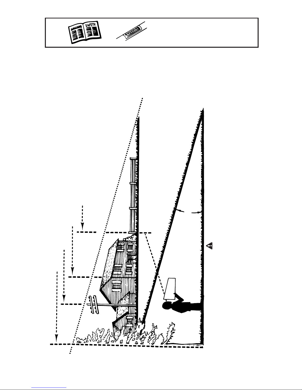
SLOPE OP ER A TION
Slopes are a ma jor fac tor re lated to slip and
fall ac cidents which can re sult in se vere in jury. Op eration on slopes re quires ex tra
caution. If you feel un easy on a slope, do
not mow it. For your safety, use the slope
gauge in cluded as part of this man ual to
measure slopes be fore op erating this unit on
a sloped or hilly area. If the slope is greater
than 15 de grees, do not mow it.
DO:
• Mow across the face of slopes; never up
and down. Ex ercise ex treme cau tion when
changing di rection on slopes. Watch for
holes, ruts, bumps, rocks, or other hid den
objects which can cause you to slip or trip.
Tall grass can hide ob stacles. Al ways be
sure of your foot ing. A slip and fall can
cause se rious personal in jury. If you feel you
are losing your balance, re lease the blade
con trol han dle im me di ately, and the blade
will stop ro tating within 3 sec onds.
DO NOT:
• Do not mow near drop-offs, ditches or em-
bankments, you could lose your foot ing or
bal ance.
• Do not mow slopes greater than 15 de grees
as shown on the slope gauge.
• Do not mow on wet grass. Un stable foot ing
could cause slip ping.
CHILDREN
• Tragic ac cidents can oc cur if the op erator is
not alert to the presence of chil dren. Children
are of ten at tracted to the mower and the
mowing ac tivity. They do not un derstand the
dangers. Never as sume that chil dren will re main where you last saw them.
a) Keep chil dren out of the mow ing area
and un der the watch ful care of a re sponsible adult other than the operator.
b) Be alert and turn mower off if a child en-
ters the area.
c) Before and while mov ing back wards, look
behind and down for small chil dren.
d) Use ex treme care when ap proaching
blind cor ners, door ways, shrubs, trees, or
other ob jects that may obscure your vi sion of a child who may run into the
mower.
e) Keep chil dren away from hot or run ning
engines. They can suf fer burns from a hot
muf fler.
• Never al low chil dren un der 14 years old to
operate a power mower. Children 14 years
old and over should read and un derstand
the operation in structions and safety rules in
this manual and should be trained and su pervised by a par ent.
SERVICE SAFE HAN DLING OF GAS OLINE:
• To avoid per sonal in jury or prop erty dam age
use ex treme care in handling gasoline. Gasoline is ex tremely flammable and the va pors
are ex plo sive. Se ri ous per sonal in jury can
occur when gasoline is spilled on yourself or
4

your clothes which can ig nite. Wash your
skin and change clothes im mediately.
a) Use only an ap proved gas oline con tainer.
b) Never fill containers in side a ve hicle or on
a truck or trailer bed with a plas tic liner.
Always place containers on the ground
away from your ve hicle be fore fill ing.
c) When prac ti cal, re move gas-pow ered
equipment from the truck or trailer and
refuel it on the ground. If this is not possible, then re fuel such equipment on a
trailer with a por table container, rather
than from a gas oline dis penser noz zle.
d) Keep the nozzle in con tact with the rim of
the fuel tank or con tainer opening at all
times un til fueling is com plete. Do not
use a noz zle lock-open de vice.
e) Ex tin guish all cig a rettes, ci gars, pipes
and other sources of ignition.
f) Never fuel machine in doors.
g) Never re move gas cap or add fuel while
the en gine is hot or run ning. Al low en -
gine to cool at least two minutes be fore
re fu el ing.
h) Never over fill fuel tank. Fill tank to no
more than ½ inch be low bot tom of filler
neck to pro vide space for fuel ex pansion.
i) Replace gas oline cap and tighten se -
curely.
j) If gas oline is spilled, wipe it off the en gine
and equip ment. Move unit to an other
area. Wait 5 min utes be fore start ing the
en gine.
k) Never store the machine or fuel container
inside where there is an open flame,
spark or pilot light as on a wa ter heater,
space heater, fur nace, clothes dryer or
other gas ap pliances.
l) To re duce fire haz ard, keep ma chine free
of grass, leaves, or other de bris build-up.
Clean up oil or fuel spill age and re move
any fuel soaked de bris.
m) Allow ma chine to cool at least 5 min utes
be fore stor ing.
GEN ERAL SER VICE:
• Never run an en gine in doors or in a poorly
ven ti lated area. En gine ex haust con tains carbon mon oxide, an odor less and deadly gas.
• Be fore clean ing, re pair ing, or in spect ing,
make certain the blade and all mov ing parts
have stopped. Dis connect the spark plug
wire and ground against the en gine to pre vent un in tended start ing.
• Check the blade and en gine mounting bolts
at fre quent intervals for proper tight ness.
Also, vi sually in spect blade for dam age
(e.g., bent, cracked, worn) Re place blade
with the orig i nal equip ment man u fac turer’s
(O.E.M.) blade only, listed in this manual.
“Use of parts which do not meet the orig inal
equip ment spec i fi ca tions may lead to improper per for mance and com pro mise
safety!”
• Mower blades are sharp and can cut. Wrap
the blade(s) or wear gloves, and use ex tra
cau tion when ser vic ing them.
• Keep all nuts, bolts, and screws tight to be
sure the equipment is in safe working con dition.
• Never tamper with safety de vices. Check
their proper op er a tion reg u larly.
• After strik ing a for eign ob ject, stop the en-
gine, dis connect the spark plug wire and
ground against the en gine. Thoroughly in spect the mower for any dam age. Re pair the
dam age be fore start ing and op er at ing the
mower.
• Grass catcher com ponents, dis charge cover,
and trail shield are sub ject to wear and
damage which could expose mov ing parts
or al low ob jects to be thrown. For safety
pro tec tion, fre quently check com po nents
and re place im me di ately with orig i nal equipment manufacturer’s (O.E.M.) parts only,
listed in this man ual. “Use of parts which do
not meet the orig i nal equip ment spec i fi ca tions may lead to im proper per formance
and com pro mise safety!”
• Do not change the en gine governor setting
or overspeed the en gine. The governor con trols the max imum safe op erating speed of
the en gine.
• Maintain or re place safety and in struction la-
bels, as nec essary.
• Observe proper dis posal laws and reg ula-
tions. Im proper dis posal of flu ids and
ma te ri als can harm the en vi ron ment.
SI-102
7.23.03
5
OWNER'S
MAN UAL
.YLEFASET AR EPOTONYAMUOYEREHWSEPOLSENI MRE TEDOTEDIUGASATEEHSSIHTESU
SAFETY LA BEL
WARNING - Your Re spon si bil ity:
Restrict the use of this power ma chine to per sons who
read, un derstand and follow the warn ings and in structions in this manual and on the ma chine.
SLOPE GAUGE
(Keep this sheet in a safe place for fu ture reference.)
.)teef01yr eveteef½2yleta m ixor ppafoesira(seer ged51fosse cxeniepolsahtiwsenil cninowomtonoD
ti,epolsahcusn
orewomdni heb-klawagn it ar epofI.yru jnisu oi resesuacdnanru trevodluocrewomgn idirA
.yru jnisu oi resnign itlu ser
.sepolsnwoddnapureven,sepolsfoecafehtssorcasr ewomDNI HEB-KLAWet ar epO
TSOPECNEFARO
GNIDLIUBAFORENROCA
EPOLS
o
51AGNITNE SE RPER,ENILDETTODNODLOF
ELOPREWOPA
LOHDNATHGISEERTLA CI TREVAHTIWLEVELSIHTD
51 º
REGNAD
.sepolsfoecafehtssorcareven,sepolsnwoddnapus
,pilsdluocuoydnagn itoofruoynia tniamottlu ci ffidylemer txesi
r ewomGNIDIRet ar epO
6
SET-UP INSTRUCTIONS
This unit is shipped WITHOUT GASOLINE
or OIL. After assembly, service engine with
gasoline and oil as instructed in the separate
engine manual packed with your unit.
NOTE: Reference to right or left
hand side of the mower is observed
from the operating position.
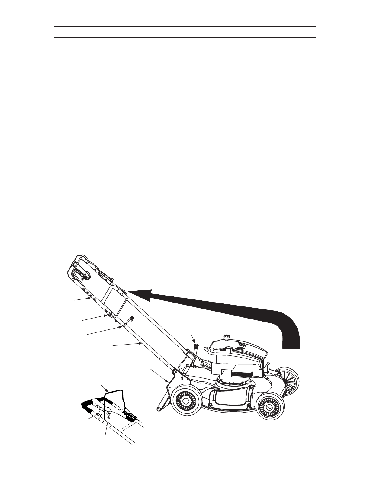
HOW TO SET-UP YOUR LAWN MOWER
Re fer to Il lus tra tion Be low
• Disconnect the spark plug wire and move it
away from spark plug as instructed in the
separate en gine man ual packed with your
unit.
• Remove the car ton in serts (if any). Re move
the loose parts which are in the carton, lift
the mower from the car ton, or cut the cor ners of the carton and roll the mower out.
• Pull up and back on the upper han dle to
raise the han dle into the operating po sition.
See Fig ure 1. Make cer tain the lower han dle
is seated se curely into the han dle mounting
brackets. Tighten the wing nuts on each side
of the handle. See Fig ure 2.
• Remove the hairpin clips from the outer hole
in the weld pins on the handle mounting
brackets. Place the hair pin clips in the in ner
hole. See Fig ure 2.
• Place one car riage bolt (found in the hard -
ware pack in cluded with your unit) in the
upper hole of the right handle mounting
bracket from the inside outward. Se cure
with one plas tic wing nuts. Re peat pro cess
on other side. See Fig ure 2.
NOTE: Make certain the drive ca ble is
routed around the out side and above
the lower handle so it does not in terfere
with at taching the grass bag.
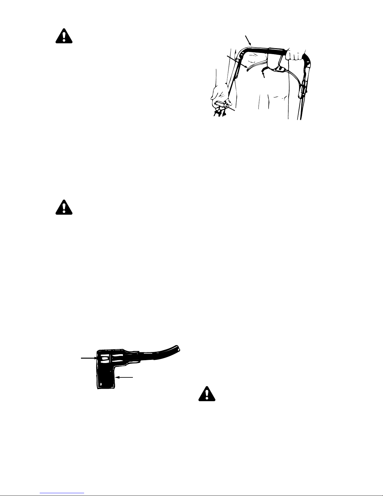
• The rope guide (pigs tail) is part of the grass
catcher support rod at tached to the lower
handle. See Fig ure 3. With the spark plug
wire dis con nected and grounded as in structed in the sep arate en gine manual,
hold the blade con trol han dle against the up per han dle, and pull the starter rope out of
the en gine slowly un til it ex tends past the
rope guide (pigs tail).
• Guide the starter rope around the rope guide
(pig tail) un til the rope is securely in the cen ter.
• Make certain all nuts and bolts are tightened
se curely.
Upper
Handle
Wing Nut
Rope Guide
Lower Handle
Handle Mounting
Blade Control Handle
Drive Clutch
Control
Shift Lever
Fig ure 1
Cutting Height
Adjustment Lever
Bracket
7
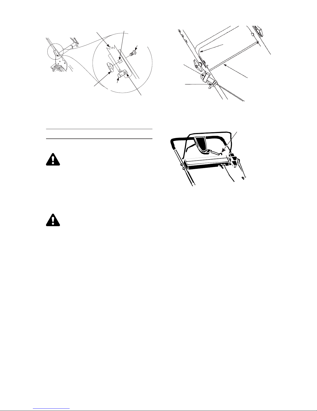
Lower Handle
Upper Hole
Carriage
Bolt
Lower
Handle
Recoil
Starter
Wing Nut
Place the hairpin clips in the inner hole.
Fig ure 2
Weld Pin
CONTROLS
BLADE CONTROL HANDLE
WARNING: This con trol mech anism
is a safety de vice. Never at tempt to
by pass its op er a tions.
The blade con trol han dle is located on the
upper han dle of the mower. See Fig ure 1.
The blade control han dle must be de pressed
in or der to op erate the unit. Re lease the
blade con trol han dle to stop the en gine and
blade.
WARNING: The blade will be rotating whenever the en gine is run ning.
Rope
Guide
Fig ure 3
Ignition Key (Switch)
Figure 4-(Electric Start Units Only)
NOTE: Only move the shift le ver when
the engine is run ning. Changing the
shift le ver setting with the en gine off
can cause dam age to the mower.
Support
Rod
RECOIL STARTER
The recoil starter handle is attached to the
handle. See Figure 3. Stand behind the unit
in the operating position to start the unit.
IGNITION SWITCH (Electric Start Units
Only)
The ignition switch is located on the left side
of the handle panel. It is used for starting
only. See Figure 4.
DRIVE CLUTCH CONTROL
Squeezing the drive clutch control engages
the drive system. Releasing the clutch
control disengages the drive system.
Release the clutch control to slow down
when negotiating an obstacle, making a turn
or stopping.
SHIFT LEVER
The shift lever is located on the drive clutch
control housing on the upper handle. See
Figure 1. This lever is used to select the
forward speed of the mower. When changing
your speed selection, release the drive
clutch control.
CUTTING HEIGHT ADJUSTMENT LEVER
(Models: 959 & 979)
The height adjuster determines the cutting
height of the mower. The ad juster is located
above the left rear wheel. To ad just the cutting height, pull the le ver out and away from
the mower and then move it for ward or back
to se lect a new cutting height. See Fig ure 5.
CUTTING HEIGHT ADJUSTMENT LEVER
(Model: 999)
The rear wheel height ad juster de ter mines
the cut ting height of the mower. The adjuster
is lo cated above the left rear wheel. To ad just the cut ting height, pull the le ver out and
away from the mower and then move it for ward or back to select a new cut ting height.
See Fig ure 5.
The front wheel cut ting height is de termined
by the selection of one of six po sitions in
each caster as sembly. See Fig ure 6.
To ad just, remove the wing nut from the axle
bolt. Slide the axle bolt and spring washer
from the as sembly and se lect a cut ting
8
HIGHER
LOWER
Locking Pin
Axle Bolt
and
Spring
Washer
Cutting Height Adjustment Lever
Figure 5
height. With the spring washer on the axle
bolt re insert in the square hole de sired,
through the wheel as sembly and se cure with
the wing nut pre viously re moved.
IM POR TANT: All wheels must be placed in
the same rel a tive po si tion.
NOTE: For rough or un even lawns,
move the height ad justment le ver to a
higher po sition. This will help stop
scalp ing.
CASTER LOCK
WARNING: When op er at ing mower
on hills, front wheels should be
locked in the straight ahead po sition.
The cast ers can be locked in a straight
ahead po sition or can be left to swivel freely.
Lift and place the lock pins in the larger
holes for locked, straight ahead op eration,
place pins in smaller holes to al low cast ers
to ro tate freely.
Fig ure 6
BEFORE STARTING
MODELS WITH ELEC TRIC START ONLY:
WARNING: The bat tery con tains
corrosive fluid and toxic material.
HANDLE WITH CARE. Keep away
from chil dren. Do not punc ture, disas sem ble, mu ti late or in cin er ate.
Explosive gases could be vented
dur ing charg ing or dis charg ing. Use
in a well-ventilated area, away from
sources of ig nition.
• Charge bat tery for 16 hours be fore ini tial
use. DO NOT CHARGE LONGER THAN 20
HOURS.
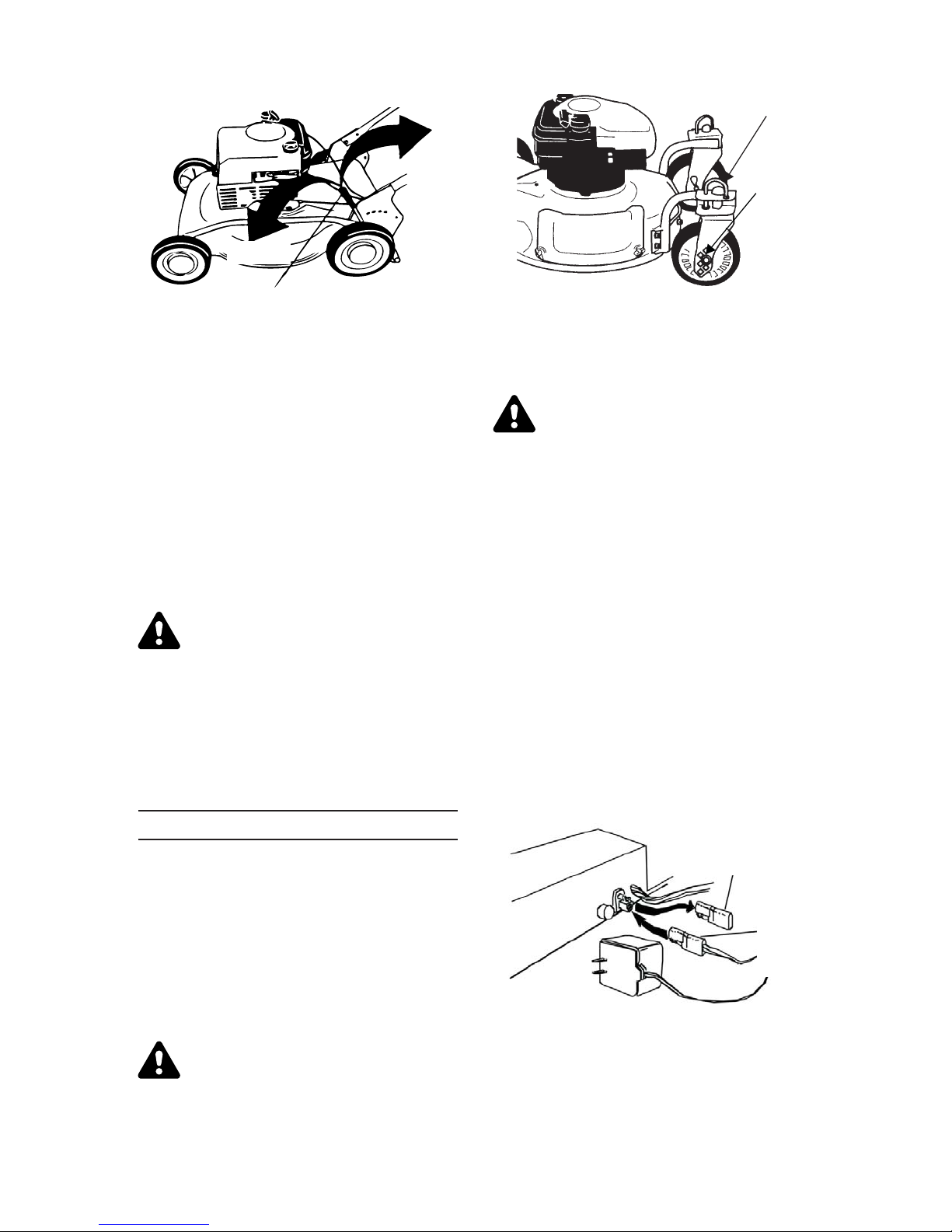
IMPORTANT: Use only the battery
charger supplied with this mower.
To charge the battery, first re move the pro -
tective cap from the end of the bat tery pack
lead. Al ways plug charger lead into bat tery
pack lead be fore in serting bat tery charger
plug into 120 volt stan dard house hold out let.
See Fig ure 7.
OPERATION
IM POR TANT: Move the shift le ver ONLY
when the en gine is run ning. Shifting the
speeds with the en gine off can cause dam age to the unit. Disengage the drive clutch
control be fore changing the speed se lection.
Service the en gine with gas oline and oil as
instructed in the sep a rate en gine man ual
packed in your mower. Read in structions
care fully.
WARNING: Never fill fuel tank indoors, with engine run ning or un til
the en gine has been al lowed to
cool for at least two minutes af ter
run ning.
Protective
Cap
Battery
pack
lead
Fig ure 7
Af ter charg ing, dis con nect bat tery charger
plug from household outlet first, then dis connect charger lead from bat tery pack lead.
9
WARNING: Do not re move the bat tery pack from the handle panel for
any rea son other than re placement.
When re placing the battery pack,
re fer to in struc tions in Main te nance
sec tion.
NEUTRAL TEST FOR ALL MODELS:
• Before each use, check for proper drive
clutch op er a tion by per form ing the fol low ing
before start ing the engine:
Blade Control Handle
Drive
Clutch
Handle
Six Speed
Shift Lever
With the drive clutch con trol re leased, push
mower for ward. It should move freely.
If it does not and the rear wheels tend to
lock up, the clutch may not be re leasing
completely. Do not start the en gine un til corrections have been made. Check the con trol
cable for se vere bend, kinks and bind ing, or
grass build-up in the pul ley groove. Refer to
the "Ad justment" section for any ad ditional
in for ma tion.
TO START ENGINE AND EN GAGE BLADE
WARNING: When starting the unit
for the first time, place mower in
first speed (slow) po sition. Face the
mower against a solid ob ject such
as a wall, fence, etc. Start the unit,
and if it shows any signs of mo tion
with the drive clutch control disengaged, shut the en gine off im mediately. Make cer tain the drive clutch
control is ad justed so the drive belt
is as loose as pos sible. Re fer to the
Ad just ment Sec tion.
• Attach spark plug wire to spark plug. If unit
is equipped with a rub ber boot over the end
of the spark plug wire, make cer tain the
metal loop on the end of the spark plug wire
(inside the rub ber boot) is fas tened se curely
over the metal tip on the spark plug. See
Fig ure 8.
Metal
Loop
on Spark
Plug Wire
Rubber Boot
Fig ure 8
• If your unit is equipped with a primer, prime
engine as in structed in the sep a rate en gine
manual packed with your unit.
• If your unit is equipped with a two speed
control on the en gine re fer to the sep arate
engine man ual packed with your unit.
Recoil Start
Handle
Figure 9-RE COIL START MODEL SHOWN
• Standing be hind the unit, de press the blade
control han dle and hold it against the up per
handle as shown in Fig ure 9.
ELECTRIC START MODELS ONLY:
• Turn the ig ni tion key to the right to start the
engine. Re lease the key af ter en gine starts.
See Fig ure 4.
NOTE: The en gine on your unit is
provided with an auxiliary re coil
starter sys tem. To start the en gine
using the auxiliary start sys tem, pro ceed as follows for recoil start
mod els:
RECOIL START MODELS ONLY:
• Grasp the re coil starter han dle as shown and
pull slowly un til re sistance is felt, then pull
rapidly to start en gine and avoid kickback.
Return it slowly to the rope guide bolt. See
Fig ure 9.
• To en gage the drive, squeeze the drive clutch
control han dle (see Fig ure 9) to wards the up per han dle. Release the drive clutch control
to slow down when ne gotiating an ob sta cle,
making a turn, or stop ping.
• The six speed shift le ver is lo cated on the
drive clutch con trol hous ing on the up per
handle. See Fig ure 9. This le ver is used to se lect the operating speed of the mower.
Release the drive clutch con trol when changing speeds.
WARNING: THIS CON TROL MECH ANISM IS A SAFETY DE VICE. NEVER
ATTEMPT TO BY PASS ITS OP ERATIONS.
The blade control han dle must be de pressed
in or der to op erate the unit. Re lease the
blade con trol han dle to stop the en gine and
blade.
10
TO STOP ENGINE
• Release the blade con trol han dle to stop the
engine and blade.
WARNING: The blade continues to
rotate for a few seconds af ter the
engine is shut off.
• Disconnect the spark plug wire and ground it
against the en gine as in structed in the separate en gine man ual to pre vent ac ci den tal
starting while equip ment is un attended.
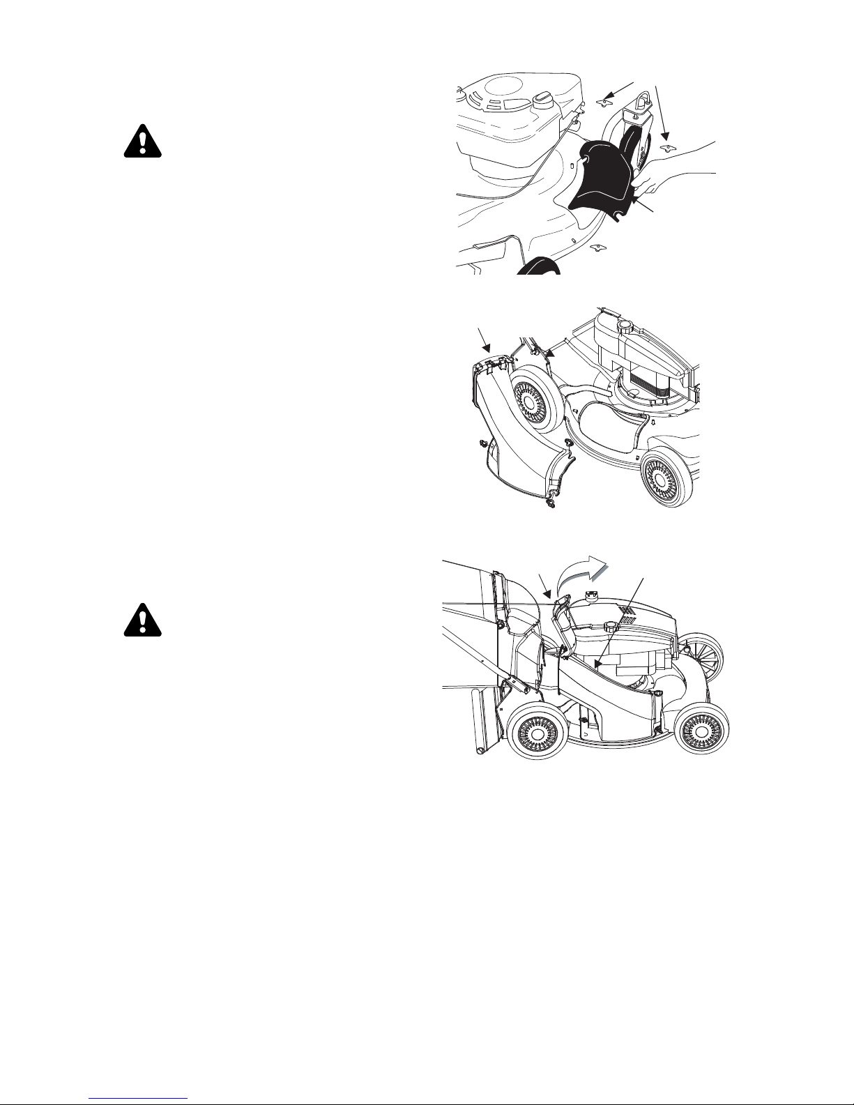
USING YOUR ROTARY MOWER
Wing Nuts
Mulching
Baffle
Be sure that lawn is clear of stones, sticks,
wire, or other ob jects which could dam age
lawn mower or en gine. Such objects could
be ac cidentally thrown by the mower in any
di rec tion and cause se ri ous per sonal in jury to
the op er a tor and oth ers.
For the best re sults, do not cut wet grass be cause it tends to stick to the un derside of the
mower, pre venting proper mulching of grass
clippings. In ad dition, wet grass could cause
you to slip and fall. New grass, thick grass or
wet grass may re quire a narrower cut.
For best re sults, cut off one-third or less of
the total length of the grass. Lawn should be
cut in the fall as long as there is growth.
The mower is designed to be op erated at full
throttle to give you the best cut and do the
most ef fective job of mulching.
WARNING: If you strike a foreign
object, stop the en gine. Re move
wire from spark plug, thor oughly in spect the mower for any dam age,
and re pair the dam age be fore re start ing and op er at ing the mower.
Ex ten sive vi bra tion of the mower
dur ing op er a tion is an in di ca tion of
damage. The unit should be
promptly inspected and repaired.
Bagging Adapter
Fig ure 11
Flap
Figure 10
Bagging
Adapter
BAGGING GRASS CLIPPINGS
This mower can bag grass clip pings. Fol low
steps 1 through 3 to ready the mower for
bag ging.
1. Remove wing nuts holding mulch ing baf fle
(see Fig ure 10) or side dis charge chute
(see Fig ure 14) in place. Then re move
baffle or dis charge chute.
2, Re place with bag ging adapter (see Fig ure
11). Attach using wing nuts. Be sure that
inner lip of attachment goes un der the
edge of the deck.
3. Lift flap and slide bag onto adapter. See
Fig ure 12.
Fig ure 12
EMPTYING YOUR GRASS BAG
Lift grassbag from the bag ging adapter using
the lower han dle. While hold ing the lower
handle lift up the rear sec tion of the
grassbag. The bag will open and the grass
clippings will fall out. See Figure 13. When
replacing your grassbag be sure the top of
the bag rests on the wire sup port be tween
the han dles.
11

nesooL
BOT TOM
VIEW
Figure 13
SIDE DISCHARGE GRASS CLIPPINGS
This mower can also side dis charge grass
clippings. Fol low steps 1 and 2 to ready this
mower for side dis charge op eration.
1. Re move mulching baf fle or grass bag
adapter. See Fig ure 10.
2. Attach discharge chute with wing nuts. See
Fig ure 14.
Side
Discharge
Chute
Wing Nut
Figure 14
ADJUSTMENT
CAUTION: DO NOT AT ANY TIME MAKE
ADJUSTMENTS TO LAWNMOWER WITH OUT FIRST STOPPING THE ENGINE AND
DISCONNECTING THE SPARK PLUG
WIRE
CAUTION: Before changing mowing
height, stop mower and disconnect
spark plug cable.
MODELS WITH SINGLE LEVER HEIGHT
ADJUSTERS:
Refer to “Controls Section” and Figure 5.
nethgiT
Figure 15
DRIVE CLUTCH CONTROL ADJUSTMENT
Use the ad justment wheel lo cated on the un derside of the clutch control hous ing to
tighten the drive belt if mower does not
self-propel with the drive clutch con trol en gaged, or if drive belt is slip ping (unit
hesitates while en gine main tains the same
speed). See Fig ure 15.
In ad dition, the adjustment wheel may also
be used to de termine the po sition in which
the drive clutch con trol is en gaged. If it is
more com fortable to have the drive engaged
with the lever fur ther away from the han dle,
tighten the drive belt.
Make certain to re test the unit for neutral as
instructed in the op eration Section. Move the
ad just ment wheel in the op po site di rec tion to
loosen the drive belt if nec essary.
SIX SPEED SHIFT CABLE ADJUSTMENT
Periodic ad justment of the six speed shift ca ble may be re quired due to nor mal stretch
and wear on the cable. Adjustment is
needed if all six speeds can not be ob tained.
The ad justable ca ble bracket is lo cated on
the left side of the mower, be side the en gine.
To adjust, loosen the hex nut which se cures
the ad justable ca ble bracket. See Fig ure 16.
Pull back ward on the bracket (toward the
rear of the mower). Retighten the hex nut.
Test the speeds on the mower (en gine must
be run ning).
CARBURETOR ADJUSTMENT
Refer to the sep arate en gine man ual packed
with your mower for car buretor ad justment
in for ma tion.
12

Hex Nut
Adjustable
Cable Bracket
Fig ure 16
Six Speed
Cable
LUBRICATION
CAUTION: DISCONNECT SPARK
PLUG WIRE BEFORE SERVICING.
WHEELS - If your mower is equipped with
ball bearing wheels, lu bricate at least once a
season with a light oil, all other types re quire
no lu brication. However, if the wheels are removed for any rea son, lu bricate the sur face
of the axle bolt and the in ner sur face of the
wheel with light au tomotive oil.
ENGINE - Follow en gine man ual for lu brication
in struc tions.
BLADE CON TROL - Lu bricate the pivot points
on the blade control han dle and the brake ca ble
at least once a sea son with light oil. The blade
control must op erate freely in both di rections.
TRANS MIS SION - The trans mission is
pre-lubricated and sealed at the fac tory. It
does not re quire checking. If dis assembled
for any reason, fill with 2 ounces of Alvania
grease, part num ber 737-0168.
MAINTENANCE
For best re sults your blade should be sharp.
The blade may be resharpened by re moving
it and ei ther grinding or filing the cutting
edge keep ing as close to the orig inal bevel
as pos si ble.
Improper blade balance will re sult in ex cessive vi bra tion caus ing even tual dam age to
the en gine and mower. Be sure to carefully
bal ance blade af ter sharp en ing.
After pro longed use, es pecially in sandy soil
conditions, the blade will be come worn and
lose some of the orig inal shape. Cut ting ef ficiency will be re duced and the blade should
be re placed. Re place with an ap proved fac tory
re place ment blade only. Pos si ble dam age resulting from blade un balance con dition is not
the re spon si bil ity of the man u fac turer.
ENGINE
Refer to the sep arate en gine man ual for en gine main te nance in struc tions.
Main tain en gine oil as in structed in the sep a-
rate en gine man ual packed with your unit.
Read and follow in structions carefully.
Un der nor mal con di tions ser vice air cleaner
as in structed in the separate en gine man ual
packed with your unit. Clean ev ery few
hours un der ex tremely dusty conditions.
Poor en
ally in dicates that the air cleaner should be
ser viced.
The spark plug should be cleaned and the
gap re set once a sea son. Spark plug re placement is recommended at the start of each
mowing sea son; check en gine man ual for correct plug type and gap spec ifications.
Clean the en gine reg ularly with a cloth or
brush. Keep the cooling system (blower housing area) clean to per mit proper air circulation
which is es sential to en gine per formance and
life. Be certain to re move all grass, dirt and
com bus ti ble de bris from muf fler area.
DECK
The un derside of the mower deck should be
cleaned after each use to prevent a buildup of
grass clippings, leaves, dirt or other mat ter. If
this de bris is al lowed to ac cumulate, it will in vite rust and cor rosion, and may pre vent
proper mulching.
The deck may be cleaned by tilt ing the mower
and scraping clean with a suit able tool (make
certain the spark plug wire is dis connected).
CUTTING BLADE
Tip mower as spec ified in separate en gine
manual. If it is not spec ified tip with car buretor
up.
gine performance and flooding usu-
NOTE: This spark ignition sys tem meets
all re quire ments of the Ca na dian In ter fer ence-Causing Equip ment Reg u la tions.
WARNING: Be sure to dis connect
and ground the spark plug wire and
re move ig ni tion key be fore work ing
on the cut ting blade to prevent ac ciden tal en gine start ing. Pro tect hands
by using heavy gloves or a rag to
grasp the cut ting blade.
13

Remove the bolt and blade sup port which
holds the blade and adapter to the en gine
crankshaft. Re move the blade and adapter
from the crank shaft.
WARNING: Pe ri odically in spect the
blade adapter for cracks, es pecially if
you strike a for eign ob ject. Re place
when nec es sary.
For best re sults your blade should be sharp.
The blade may be resharpened by re moving it
and ei ther grinding or fil ing the cutting edge
keeping as close to the orig inal bevel as pos sible. It is ex tremely im portant that each
cutting edge receives an equal amount of
grinding to prevent an un balanced blade. Im proper blade bal ance will re sult in ex cessive
vibration causing even tual damage to the en gine and mower. Be sure to care fully bal ance
blade af ter sharp ening. The blade can be
tested for bal ance by bal ancing it on a round
shaft screw driver. Re move metal from the
heavy side un til it bal ances evenly.
Before re assembling the blade and the blade
adapter to the unit, lu bricate the en gine crankshaft and the in ner sur face of the blade
adapter with light oil. In stall the blade adapter
on the crankshaft with the “star” away from the
engine. Re fer to Fig ure 18. Place the blade
with the side marked bot tom (or with part
number) fac ing away from the adapter. Align
the blade bell sup port over the blade with the
tabs in the holes of the blade and in sert the
hex bolt. Tighten the hex bolt to the torque
listed be low:
Blade Mounting Torque
After pro longed use, es pecially in sandy soil
conditions, the blade will be come worn and
lose some of the orig
inal shape. Cut ting ef ficiently will be re duced and the blade should be
replaced. Re place with an ap proved fac tory re placement blade only. Pos sible dam age
re sult ing from blade un bal ance con di tion is not
the re spon si bil ity of the man u fac turer.
BELT REMOVAL AND REPLACEMENT
1. Dis connect the spark plug wire and
ground it against the engine.
2. Drain the fuel tank or place a piece of plas tic be neath the cap to prevent gasoline
leak age.
3. Tip the mower on its side. Block se curely.
4. Re move the blade and blade adapter as
de scribed previously.
5. Move rear height adjuster to the highest
po si tion. See Fig ure 21.
6. Using a 3/8" socket re move three hex
screws holding the baffle to the deck. See
Fig ure 19.
Hex
Screw
Hex
Hex
Screw
Screw
Center Bolt 450 in. lb. min., 600 in.lb. max.
To in sure safe op eration of your unit, ALL
nuts and bolts must be checked pe riodically
for cor rect tight ness.
CAUTION: Cutting grass in sandy
soil conditions causes abrasive
wear to the blade.
Blade Adapter
Blade
Blade Bell
Support
Hex Bolt
Figure 18
Figure 19
Baffle
Figure 20
7. Pivot baf fle to wards the rear of the mower.
See Fig ure 20.
8. Re move the hex bolt holding the transmission to the mower hous ing. See Figure
21.
14
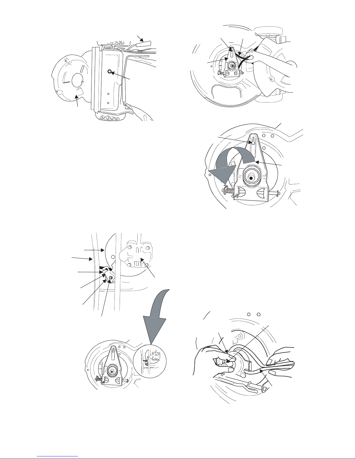
Rear Wheels Adjustment Lever
Hex
Bolt
Six-Speed
Cable Slot
Control
Arm
Belt
Baffle
Figure 21
9. Tilt the trans mission for ward and loosen
the idler pul ley bolt and locknut ½ turn
using two 7/16" wrenches.
10. Using a pair of pli ers, pull back and ro tate
belt keeper bracket from the slot on idler
pul ley.
11. Slide the belt out from be tween the belt
keeper bracket and the idler pul ley. See
Fig ure 22.
12. Squeeze the belt to gether and push belt
forward. Press the con trol arm in ward to wards the deck and re move the six speed
cable from the slot. See Fig ure 23.
Transmission
Pulley
Belt
Belt Keeper
Bracket
Idler Pulley
Transmission
Bracket
Figure 23
Six-Speed
Cable Slot
Control
Arm
Figure 24
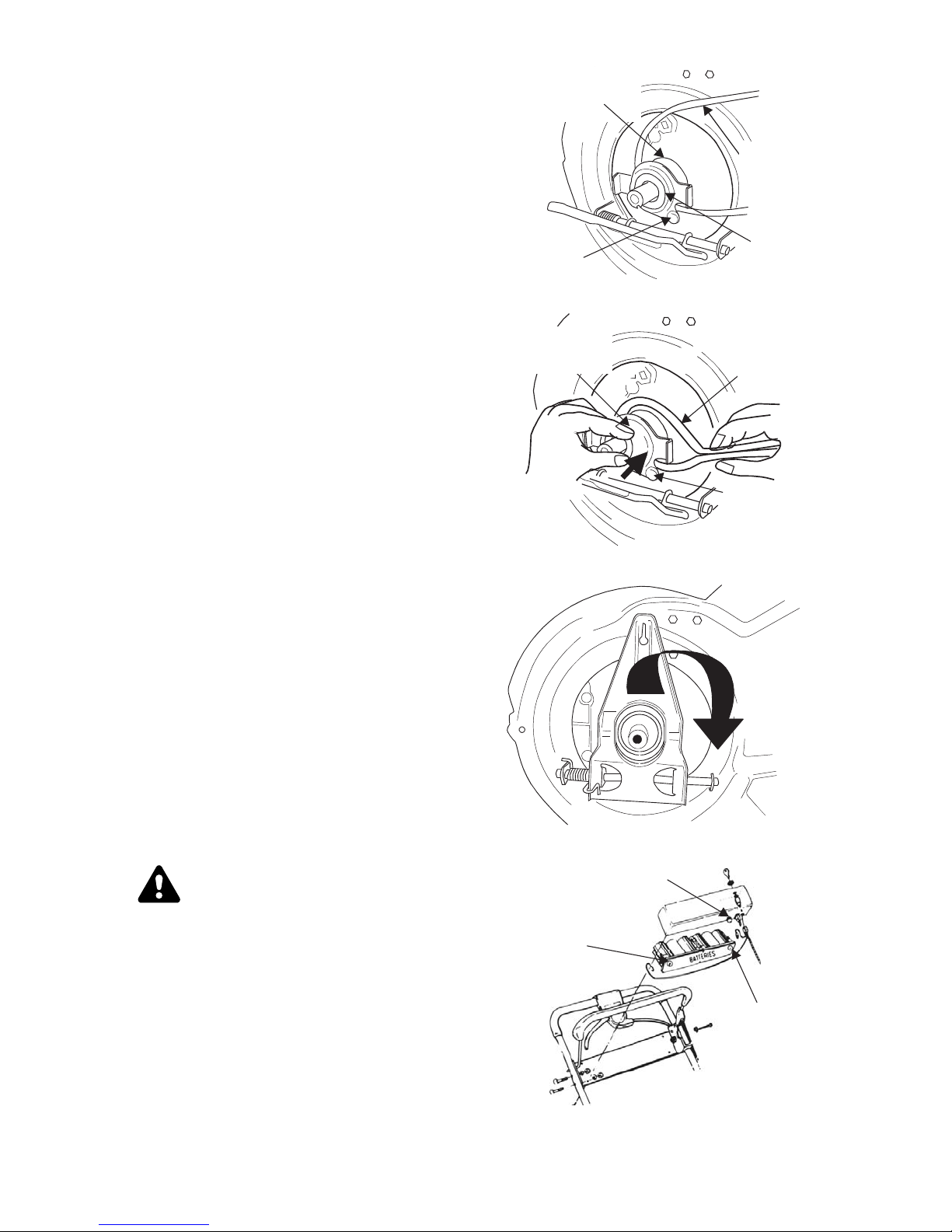
13. Pivot the con trol arm down away from the
pulley and belt. See Fig ure 24.
14. Lift off the lower pul ley as sembly and re move the old belt from around the
crankshaft. See Figure 25.
15. Place the new belt over the trans mission
pulley. Start the belt in pul ley groove and
rotate pulley until belt is seated in transmission pul ley. See Fig ure 25.
16. Place belt be tween idler pul ley and the
belt keeper bracket.
Idler Pulley
Bolt and
Locknut
Figure 22
Mower is shown tipped on en gine for clarity.
Remember, only tip mower back on its han dle with the spark plug facing up.
Figure 25
15
Lower Pulley
Half
Crankshaft
Belt
17. Using pli ers, rotate the belt keeper bracket
so that it snaps into slot on the idler
bracket.
18. Tighten the idler pul ley bolt and locknut ½
turn us ing two 7/16" wrenches. See Fig ure
22.
19. Place belt be tween the two pul ley halves on
the crank shaft. Make sure to route the belt
inside the belt guard pin. See Fig ure 26.
IM POR TANT: For proper as sembly, it
is es sential to keep the as sembly
positioned as shown in Figure 26.
20. Pinch belt to gether so that it is not in the pulley groove, and the lower pul ley can be
pushed to wards the en gine. See Fig ure 27.
21. Pivot the con trol arm back to its orig inal po sition and re install the six-speed ca ble into the
slot.
22. Check and make sure the belt is routed in side the pul ley halves and the belt guard
pin. See Fig ure 28.
23. Re in stall the bolt se cur ing trans mis sion to
rear mower hous ing.
24. Pivot the baf fle back to its orig inal po sition
and se cure with three hex screws ear lier re moved. You will need a 3/8" socket for these
screws.
25. Lightly lu bricate the crank shaft and re install
blade and blade adapter as de scribed in the
“Cutting Blade” sec tion.
26. Tip the mower back on its wheels.
27. Make cer tain to re test the unit for neutral as
in structed in the Op er a tion Sec tion.
Upper Pulley
Belt Guard
Pin
Figure 26
Lower Pulley
Half
Figure 27
Half
Belt
Lower
Pulley
Half
Belt
Belt Guard
Pin
BATTERY PACK REPLACEMENT (Electric
start Models Only)
Remove the bat tery pack from the han dle panel
for replacement only. Do not separate the bat teries for any rea son. Dis pose of bat teries
prop erly.
WARNING: Bat teries con tain sul furic acid which may cause burns. Do
not short cir cuit or mu
tilate in any
way. Do not put bat teries in fire.
They may burst or release toxic ma te rial.
When re placing bat tery pack in han dle
panel, bat tery pack must be po sitioned with
the positive ter minal to the right hand side
and the neg ative terminal to the left hand
side of panel. See Fig ure 29. Replacing the
battery pack in correctly will cause se rious
dam age.
The pos itive lead on the wire har ness has
the smaller connector. Con nect the pos itive
Figure 28
Fuse Holder
Positive
terminal
Negative
terminal
Figure 29
16
 Loading...