

YAMAHA TDM850 User Manual

FOREWORD
This Supplementary Service Manual has been prepared to introduce new service and data for the TDM850
’97. For complete service information procedures it is necessary to use this Supplementary Service Manual
together with the following manual.
TDM850 ’96 SERVICE MANUAL: 4TX-AE1
TDM850 ’97
SUPPLEMENTARY
SERVICE MANUAL
1996 by Yamaha Motor Co., Ltd.
First Edition, October 1996 All rights
reserved.
Any reproduction or unauthorized use
without the written permission of
Yamaha Motor Co., Ltd.
is expressly prohibited.
EB001000
NOTICE
This manual was produced by the Y amaha Motor Company primarily for use by Y amaha dealers and their
qualified mechanics. It is not possible to include all the knowledge of a mechanic in one manual, so it is
assumed that anyone who uses this book to perform maintenance and repairs on Y amaha motorcycles has
a basic understanding of the mechanical ideas and the procedures of motorcycle repair. Repairs attempted
by anyone without this knowledge are likely to render the motorcycle unsafe and unfit for use.
Y amaha Motor Company , Ltd. is continually striving to improve all its models. Modifications and significant
changes in specifications or procedures will be forwarded to all authorized Y amaha dealers and will appear
in future editions of this manual where applicable.
NOTE:
Designs and specifications are subject to change without notice.
IMPORTANT INFORMATION
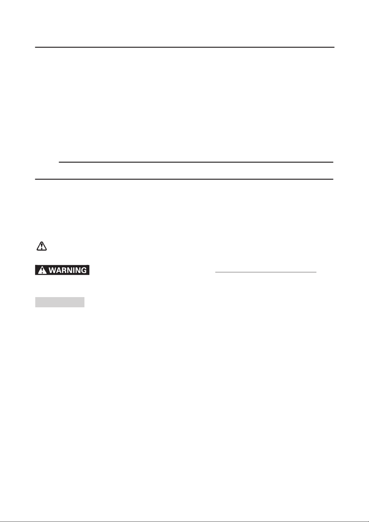
Particularly important information is distinguished in this manual by the following notations.
The Safety Alert Symbol means A TTENTION! BECOME ALERT! YOUR SAFETY
IS INVOLVED!
Failure to follow WARNING instructions could result in severe injury or death
motorcycle operator, a bystander or a person inspecting or repairing the motorcycle.
CAUTION:
NOTE: A NOTE provides key information to make procedures easier or clearer.
A CAUTION indicates special precautions that must be taken to avoid damage to
the motorcycle.
to the
EB002000
HOW TO USE THIS MANUAL
MANUAL ORGANIZATION
This manual consists of chapters for the main categories of subjects. (See “Illustrated symbols”.)
1st title
2nd title
1 : This si the title of the chapter with its symbol in the upper right corner of each page.
2 : This title indicates the section of the chapter and only appears on the tirst page of each section.
It is located in the upper left corner of the page.
3rd title
3 : This title indicates a sub-section that is followed by step-by-step procedures accompanied by
corresponding illustrations.
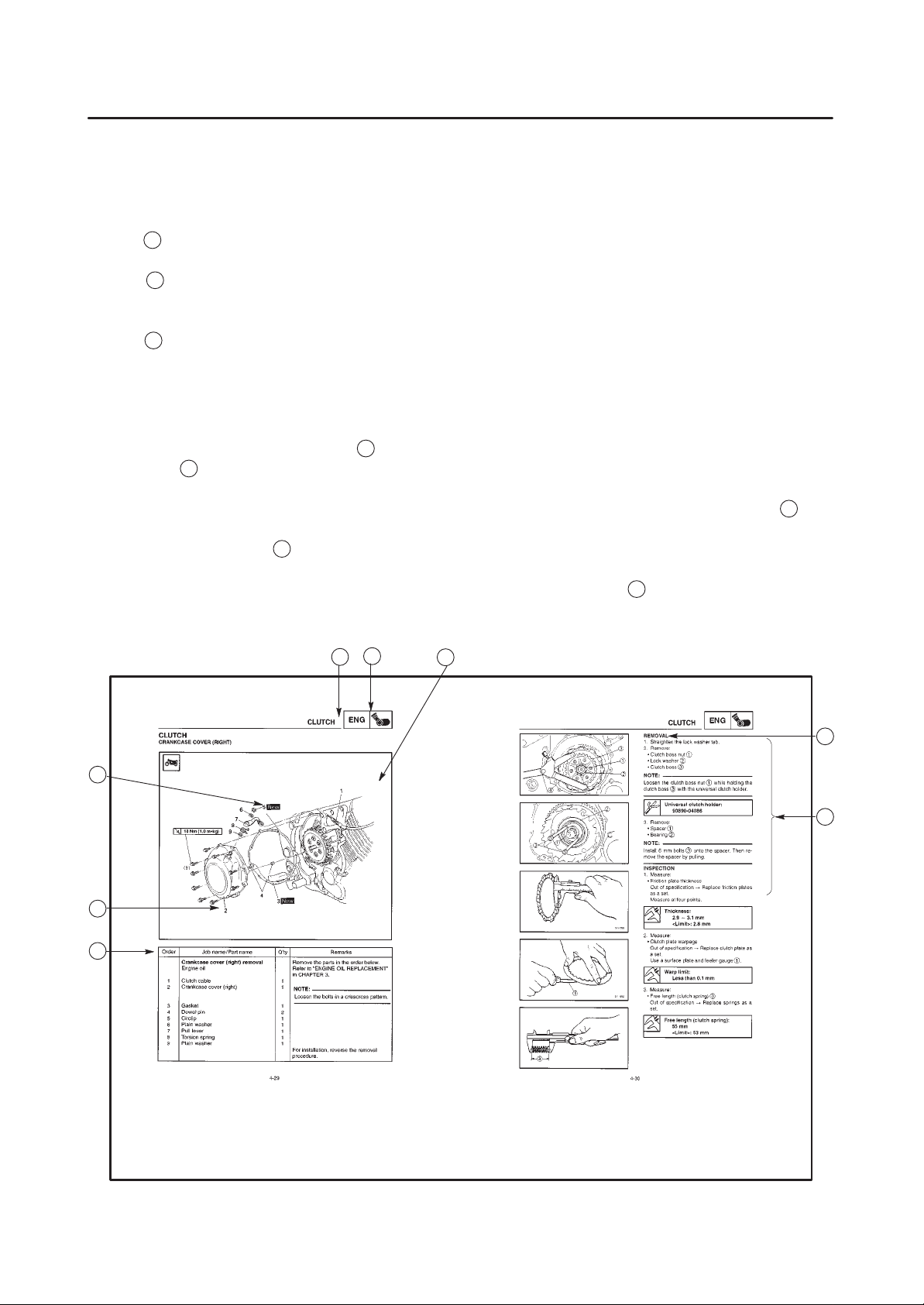
EXPLODED DIAGRAMS
T o help identify parts and clarify procedure steps, there are exploded diagrams at the start of each removal
and disassembly section.
1. An easy-to-see exploded diagram
2. Numbers
5 are given in the order of the jobs in the exploded diagram. A number that is enclosed by
4 is provided for removal and disassembly jobs.
circle indicates a disassembly step.
3. An explanation of jobs and notes is presented in an easy-to-read way by the use of symbol marks
6 . The
meanings of the symbol marks are given on the next page.
4. A job instruction chart
7 accompanies the exploded diagram, providing the order of jobs, names of
parts, notes in jobs, etc.
5. For jobs requiring more information, the step-by-step format supplements
8 are given in addition to the
exploded diagram and the job instruction chart.
1
2
4
3
6
8
5
7
 Loading...