

Yamaha RX-V2083, RX-V3083 Quick Start Manual
AV Receiver
EN
ZH
Ampli-tuner audio-vidéo
TA
Quick Start Guide
快速启动指南
Safety Instructions ................................................ 3
Connections .......................................................... 5
Basic operations ................................................. 16
安全说明 ........................................................... 20
连接 ................................................................... 25
基本操作 ........................................................... 37
English
中文
English
A (power) key
Turns on the power of this unit or sets it to the standby mode.
This product is for ordinary homes. Do not use for applications requiring high reliability, such as
managing lives, health care or high-value assets.
For more detailed information, refer to the Owner’s Manual on the CD-ROM. To view the Owner’s
Manual, click on “English” in the screen displayed automatically when you insert the CD-ROM
into your PC, or click on the model name if the screen to select models is displayed, and then click
on “English” in the next screen. Then, follow the onscreen instructions.
If the screen is not displayed automatically, open the “index.html” in the CD-ROM.
Caution: Do not attempt to play this CD-ROM in an audio player.
The Owner’s Manual contained in the CD-ROM can be downloaded from the following website.
http://download.yamaha.com/
Do not use this unit within 22 cm (9 inches) of persons with a heart pacemaker implant or
defibrillator implant.
Caution
Do not touch the surface marked with this label.
The surface may become hot during operation.
2 En
CAUTION: READ THIS BEFORE OPERATING YOUR UNIT.
1 To assure the finest performance, please read this manual carefully. Keep it in a safe place for future
reference.
2 Install this sound system in a well ventilated, cool, dry, clean place - away from direct sunlight, heat
sources, vibration, dust, moisture, and/or cold. For proper ventilation, allow the following minimum
clearances.
Top: 30 cm, Rear: 20 cm, Sides: 20 cm
3 Locate this unit away from other electrical appliances, motors, or transformers to avoid humming
sounds.
4 Do not expose this unit to sudden temperature changes from cold to hot, and do not locate this unit in
an environment with high humidity (i.e. a room with a humidifier) to prevent condensation inside
this unit, which may cause an electrical shock, fire, damage to this unit, and/or personal injury.
5 Avoid installing this unit where foreign object may fall onto this unit and/or this unit may be exposed
to liquid dripping or splashing. On the top of this unit, do not place:
– Other components, as they may cause damage and/or discoloration on the surface of this unit.
– Burning objects (i.e. candles), as they may cause fire, damage to this unit, and/or personal injury.
– Containers with liquid in them, as they may fall and liquid may cause electrical shock to the user
and/or damage to this unit.
6 Do not cover this unit with a newspaper, tablecloth, curtain, etc. in order not to obstruct heat
radiation.
If the temperature inside this unit rises, it may cause fire, damage to this unit, and/or personal injury.
7 Do not plug in this unit to a wall outlet until all connections are complete.
8 Do not operate this unit upside-down. It may overheat, possibly causing damage.
9 Do not use force on switches, knobs and/or cords.
10 When disconnecting the power cable from the wall outlet, grasp the plug; do not pull the cable.
11 Do not clean this unit with chemical solvents; this might damage the finish. Use a clean, dry cloth.
12 Only voltage specified on this unit must be used. Using this unit with a higher voltage than specified
is dangerous and may cause fire, damage to this unit, and/or personal injury. Yamaha will not be
held responsible for any damage resulting from use of this unit with a voltage other than specified.
13 To prevent damage by lightning, keep the power cable and outdoor antennas disconnected from a
wall outlet or this unit during a lightning storm.
14 Do not attempt to modify or fix this unit. Contact qualified Yamaha service personnel when any
service is needed. The cabinet should never be opened for any reasons.
15 When not planning to use this unit for long periods of time (i.e. vacation), disconnect the AC power
plug from the wall outlet.
16 Be sure to refer to the “Troubleshooting” section of the Owner’s Manual on the CD-ROM for
common operating errors before concluding that this unit is faulty.
17 Before moving this unit, press z to set it to standby mode and disconnect the AC power plug from
the wall outlet.
18 VOLTAGE SELECTOR (Taiwan, Brazil and General models)
The VOLTAGE SELECTOR on the rear panel of this unit must be set for your local main voltage
BEFORE plugging into the AC wall outlet. Voltages are:
........................................................................................................... AC 110-120/220-240V, 50/60Hz
19 Condensation will form when the surrounding temperature changes suddenly. Disconnect the power
cable from the outlet, then leave this unit alone.
20 When using this unit for a long time, this unit may become warm. Turn the power off, then leave this
unit alone for cooling.
21 Install this unit near the AC outlet and where the AC power plug can be reached easily.
22 Excessive sound pressure from earphones and headphones can cause hearing loss.
This unit is not disconnected from the AC power source as long as it is connected to the wall outlet,
even if this unit itself is turned off by A. This state is called the standby mode. In this state, this unit
is designed to consume a very small quantity of power.
WARNING
TO REDUCE THE RISK OF FIRE OR ELECTRIC SHOCK, DO NOT EXPOSE THIS UNIT TO
RAIN OR MOISTURE.
■ Notes on remote controls and batteries
• Do not spill water or other liquids on the remote control.
• Do not drop the remote control.
• Do not leave or store the remote control in the following conditions:
– places of high humidity, such as near a bath
– places of high temperatures, such as near a heater or stove
– places of extremely low temperatures
– dusty places
• Insert the battery according to the polarity markings (+ and –).
• Change all batteries if you notice the following conditions:
– the operation range of the remote control narrows
– the transmit indicator does not flash or is dim
• If the batteries run out, immediately remove them from the remote control to prevent an explosion
or acid leak.
• If you find leaking batteries, discard the batteries immediately, taking care not to touch the leaked
material. If the leaked material comes into contact with your skin or gets into your eyes or mouth,
rinse it away immediately and consult a doctor. Clean the battery compartment thoroughly before
installing new batteries.
• Do not use old batteries together with new ones. This may shorten the life of the new batteries or
cause old batteries to leak.
• Do not use different types of batteries (such as alkaline and manganese batteries) together.
Specification of batteries may be different even though they look the same.
• Before inserting new batteries, wipe the compartment clean.
• If the remote control is without batteries for more than 2 minutes, or if exhausted batteries remain in
the remote control, the contents of the memory may be cleared. In such a case, install new batteries
and set the remote control code.
• Dispose of batteries according to your regional regulations.
• Keep batteries away from children. If a battery is accidentally swallowed, contact your doctor
immediately.
• When not planning to use the remote control for long periods of time, remove the batteries from the
remote control.
• Do not charge or disassemble the supplied batteries.
• The batteries shall not be exposed to excessive heat such as sunshine, fire or like.
En 3
This document explains 7.1-channel system setup, 7.1.2-channel system
setup using the front presence speakers, and unit configuration, followed by
step-by-step instructions. Basic operations, such as playing Blu-ray Discs,
DVDs, and radio content, are also explained.
In this document, the RX-V3083 is used for illustration purposes. Some parts
or components, such as jacks or remote control keys, may vary by specific
model. Such differences are indicated as required.
The unit is equipped with a number of other functions not described in this
booklet. For more information about this product, refer to the Owner’s Manual
included on the supplied CD-ROM. The latest Owner’s Manual can be
downloaded from the following website.
http://download.yamaha.com/
The Owner’s Manual in HTML format can be viewed on your smartphone,
tablet, or PC. Visit the following website.
RX-V3083/RX-V2083
http://avpro.global.yamaha.com/manual/avr/rxv3083/
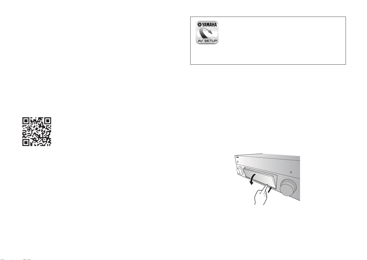
AV SETUP GUIDE
AV SETUP GUIDE is an app that guides you
through the process of connecting a TV or playback
device, such as a BD/DVD or CD player, and
speakers to the AV receiver. Search “AV SETUP
GUIDE” on the App Store or Google Play for
details.
Opening and closing the front panel door
Press the bottom of the door gently to open it when using controls or jacks
behind the front panel door. Keep the door closed when controls or jacks
behind the front panel door are not in use. (Be careful not to trap your fingers.)
[For U.S. customers only]
Visit the following website for additional information, FAQ’s, downloads such
as “Owner’s Manual” and product updates.
http://usa.yamaha.com/support/
4 En
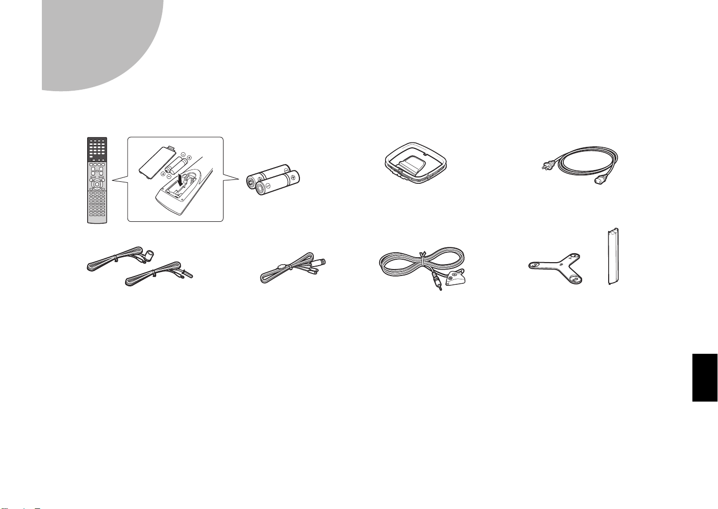
Preparation
Remote control
Batteries (AAA, R03, UM-4)
(x2)
CD-ROM (Owner’s Manual)
Quick Start Guide (this booklet)
YPAO microphone
AM antenna
(except for U.K., Europe, Australia
and Russia models)
Power cable
The supplied power cable varies
depending on the region of purchase.
FM antenna
(except for U.K., Europe, Australia
and Russia models)
One of the above is supplied depending
on the region of purchase.
DAB/FM antenna
(U.K., Europe, Australia and
Russia models)
Microphone base Pole
Use to measure angle/height
during YPAO.
1
Confirming package contents
Preparing cables
The following cables (not supplied) are required to build the system described in this document.
• Speaker cables (depending on the number of speakers)
• Audio pin cable (x1)
• HDMI cables (x3)
• Network cable (x1) (when connecting to a router via a network cable)
En 5
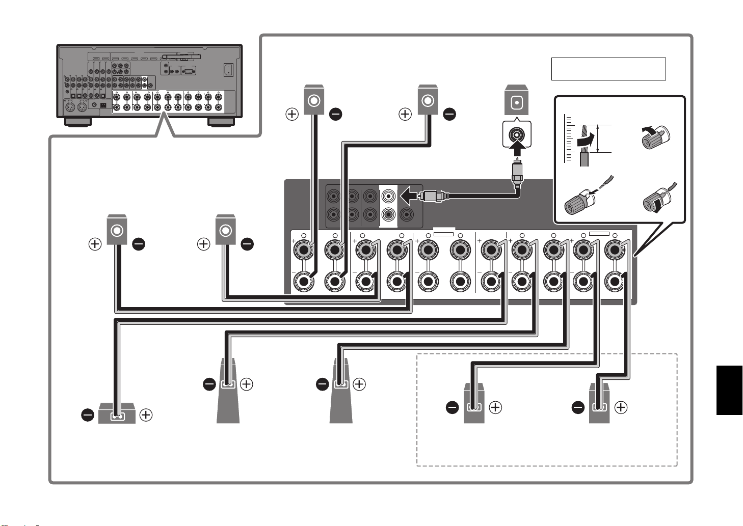
Connecting speakers/subwoofer
*
RE
3
1
2
9
54
76
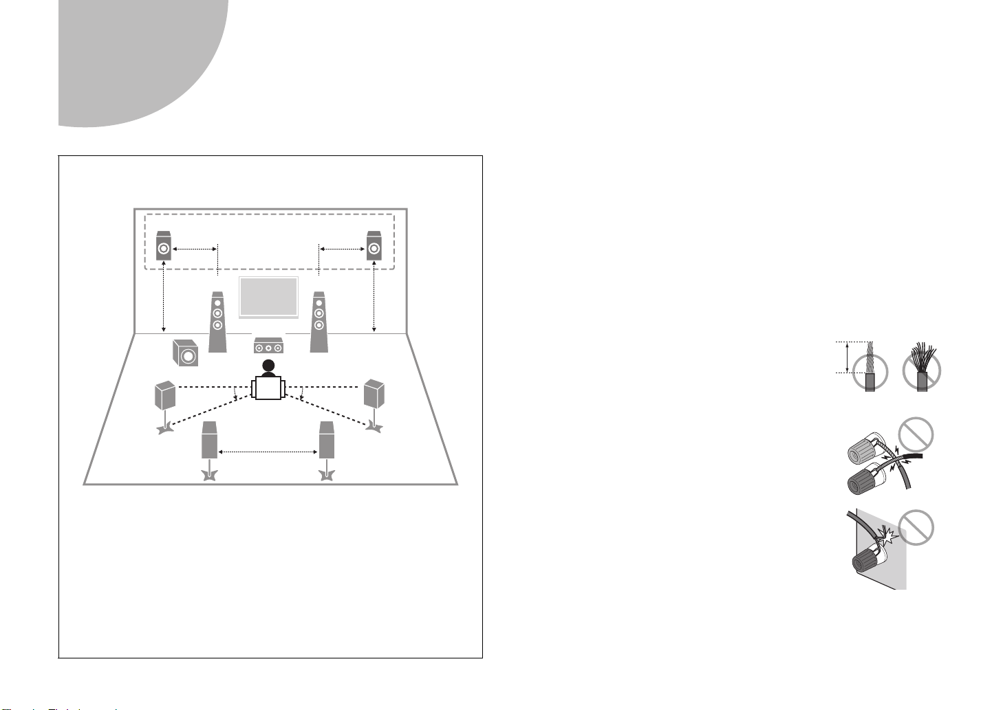
10° to 30° 10° to 30°
0.5 to 1 m
(1.6 to 3.3 ft)
0.5 to 1 m
(1.6 to 3.3 ft)
1.8 m
(5.9 ft)
1.8 m
(5.9 ft)
0.3 m (1 ft)
or more
10 mm
(3/8")
2
Positioning speakers
Use the diagram as a reference for positioning speakers.
When connecting 6-ohm speakers
Set the unit’s speaker impedance to “6 Ω MIN”. For details, see “Setting the
speaker impedance” in the Owner’s Manual.
Precautions for connecting speaker cables
• Be sure that the unit and subwoofer are turned off.
• Prepare speaker cables in a place away from the unit, to avoid accidentally
dropping wire strands into the unit's interior which could result in a short
circuit or malfunction of the unit.
• Improper connection of speaker cables could cause a short circuit resulting
in damage to, or malfunctioning of, the unit or speakers.
– Carefully remove approximately 10 mm
(3/8") of insulation from the speakerconnection ends of the cables, and twist
the bare wires of each speaker cable
together firmly.
– Do not allow the bare wires of separate speaker
cables to come into contact with one another.
6 En
1 Front speaker (L)
2 Front speaker (R)
3 Center speaker
4 Surround speaker (L)
5 Surround speaker (R)
6 Surround back speaker (L)
7 Surround back speaker (R)
E Front presence speaker (L)*
R Front presence speaker (R)*
9 Subwoofer
* For 7.1.2-channel system
– Do not allow speaker cable bare wires to come into
contact with metal parts on the unit (rear panel and
screws).
If “Check SP Wires” is shown on the front display when the unit is turned on,
turn off the unit and be sure that speaker cables have not caused a short
circuit.
R L R L
R
R
L
L
4321
R
5
6
L R RL L
B
A
R
L
2
34
1
Subwoofer
9
2
Front speaker (R)
10 mm
(3/8")
1
Front speaker (L)
3
Center speaker
Surround speaker (R)
5
Surround speaker (L)
4
Use a subwoofer equipped
with built-in amplifier.
Audio pin cable
R
Front presence speaker (R)
E
Front presence speaker (L)
For 7.1.2-channel system
Surround back speaker (R)
7
Surround back speaker (L)
6
R L R RL L
SURROUND
(SINGLE) (FRONT)
PRE OUT
SURROUND SUR. BACK
(REAR)
SUBWOOFER
SURROUND BACK
1
2
CENTERFRONT
SINGLE
SPEAKERS
EXTRA SP2
R.PRESENCE
CENTER FRONT
R L R L
EXTRA SP1
F.PRESENCE
ZONE 2/ZONE 3/F.PRESENCE
ZONE 2/ZONE 3/BI-AMP
En 7
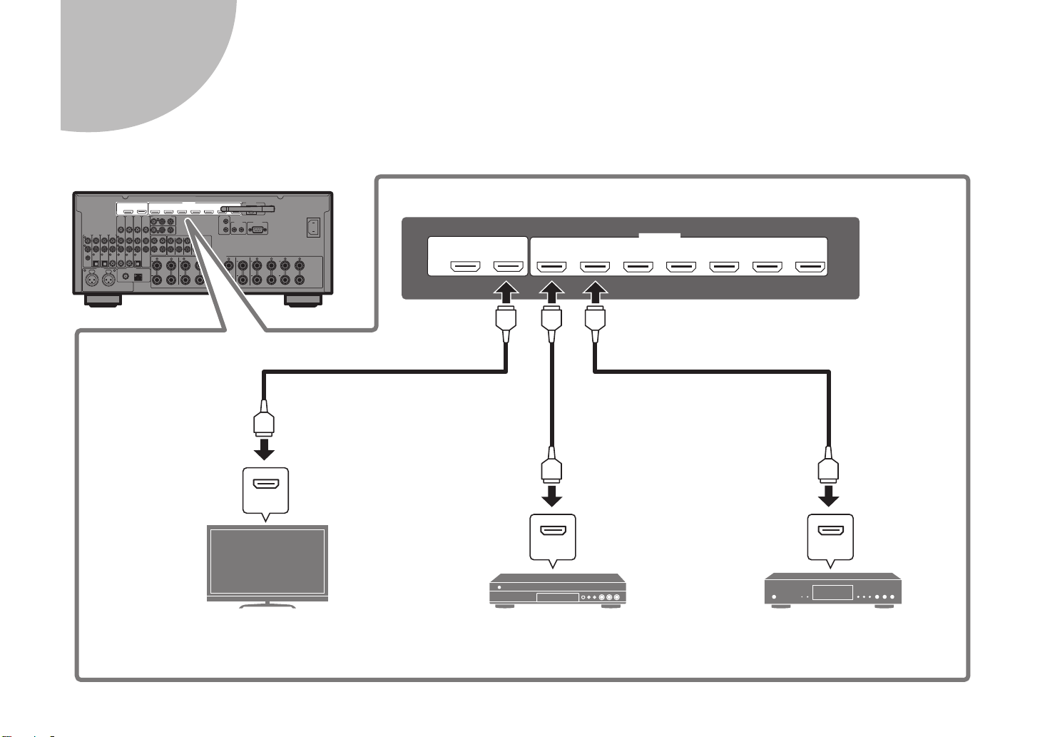
Connecting external devices
R L R L
R
R
L
L
4321
R
5
6
L R RL L
B
A
R
L
HDMI
HDMI HDMI
HDMI OUT
ARC
(ZONE OUT)
1
2
HDMI
(1 BD/DVD)
AV 1 AV 2 AV 3 AV 4
(HDCP2.2)
AV 5 AV 6 AV 7
(HDCP2.2)
HDMI HDMI HDMI
HDMI
HDMI
HDMI
TV BD/DVD player Satellite/cable set top box
HDMI input
HDMI output HDMI output
3
8 En
4
R L R L
R
R
L
L
4321
R
5
6
L R RL L
B
A
R
L
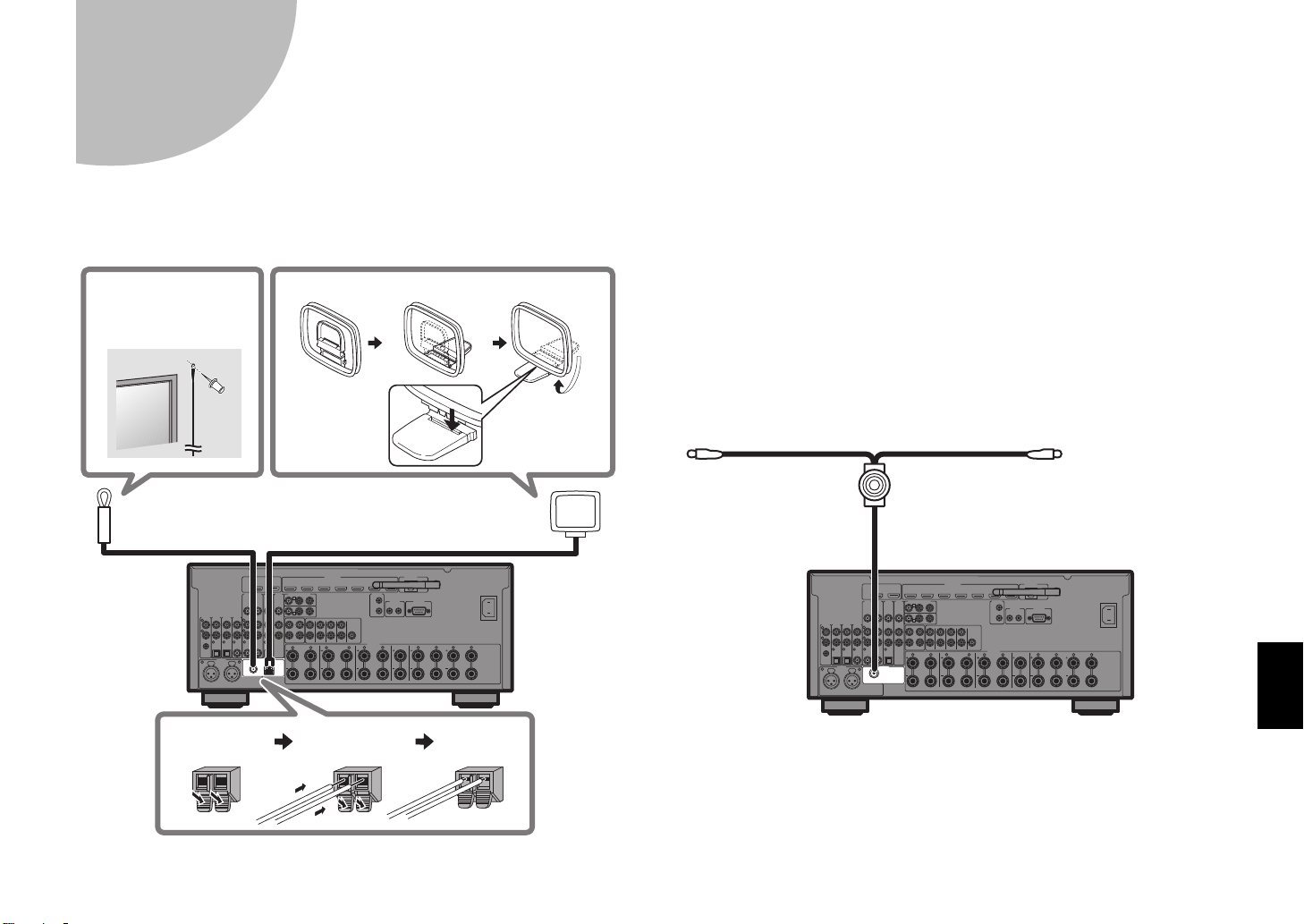
FM antenna (supplied) AM antenna (supplied)
Hold down Insert Release
Assembling the AM antenna
Place the AM
antenna on a
flat surface.
Fix the end of the
FM antenna to a
wall.
R L R L
R
R
L
L
4321
R
5
6
L R RL L
B
A
R
L
DAB/FM antenna (supplied)
Fix the antenna
ends to a wall.
Connecting the radio antennas
FM/AM antennas (except for U.K., Europe,
Australia and Russia models)
DAB/FM antenna (U.K., Europe, Australia and
Russia models)
En 9
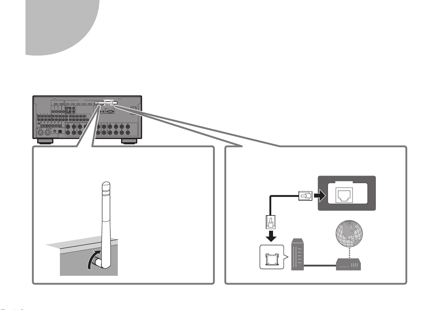
Preparing a network connection
R L R L
R
R
L
L
4321
R
5
6
L R RL L
B
A
R
L
NETWORK
( 3
NET
)
LAN
Raise the wireless
antenna so that it is
standing up straight.
(Procedures for
connecting the unit to a
wireless router are
described in step
7
.)
Notice
Do not apply excessive force
on the antenna. Doing so
may damage it.
Wireless network connection
Internet
Network cable
Router Modem
Wired network connection
5
Prepare a wired or wireless network connection in accordance with your network environment.
Note
The wireless antenna must be raised if the unit will be connected to a Bluetooth device.
10 En
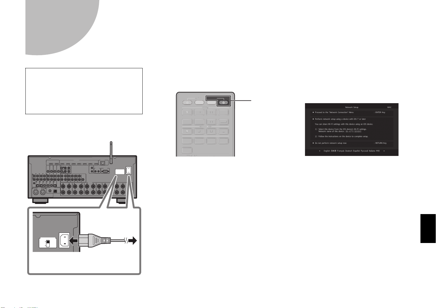
Connecting the power cable to an AC wall outlet,
R L R L
R
R
L
L
4321
R
5
6
L R RL L
B
A
R
L
To an AC
wall outlet
VOLTAGE SELECTOR
(Taiwan, Brazil and General models only)
4321
AUDIO
2 431
6 75
AV
V-AU X
BLUETO OTH
NET
USB
PHONO
TUNER
RECEIVER
SOURCE
432
1
AUDIO
3
675
V-AUX
BLUETOO
N
US
O
TU
S
E
z
6
Before connecting the power cable
(Taiwan, Brazil and General models only)
Set the switch position of VOLTAGE
SELECTOR according to your local voltage.
Voltages are AC 110–120/220–240 V,
50/60 Hz.
1 Plug the power cable into an
AC wall outlet.
VOLTAGE SELECTOR
220V240V
110V120V
AC IN
and turning on the unit
2 Press RECEIVER z to turn on
the unit.
OURC
TH
PHON
NER
3 Turn on the TV and switch the
TV input to display video from
the unit (HDMI OUT jack).
ET
B
The Network Setup screen shown below will be
displayed on the TV when the unit is turned on for
the first time after purchase. It may take several
tens of seconds for the screen to be displayed
(WAC: Wireless Accessory Configuration).
See “Sharing the iOS device setting” under
“Connecting the unit to a wireless network” in the
Owner’s Manual when using this function to
connect the unit to a network.
This document explains wireless connection
using methods other than this function. Follow
the procedure described under “Connecting the
unit to a network” on the next page.
Note
This screen will not be displayed if the unit is connected
to a router via its NETWORK jack (wired connection).
En 11
7
Connecting the unit to a network
Connecting the unit to a wireless network
• The unit can be connected to a wireless network using the MusicCast
CONTROLLER app* installed on your smartphone or other mobile device.
Follow procedure
• If a mobile device will not be used, follow procedure
to a wireless router (access point) that supports WPS. Refer to the Owner’s
Manual for details on other wireless connection methods.
Connecting the unit to a router via a network cable
• Follow procedure
your smartphone or other mobile device to connect to the MusicCast
network to play music over a network.
• If a mobile device will not be used, skip this step and proceed to step
* MusicCast CONTROLLER, an app for mobile devices, can be used to
easily configure network settings for not only this unit, but also for other
MusicCast-enabled devices. This app allows you to listen to music stored
on your smartphone or other mobile device, or on servers, and to listen to
Internet radio stations. It also allows you to play this rich variety of music
content on all devices in the MusicCast network at the same time.
Visit the following website for details.
http://www.yamaha.com/musiccast/
A .
B to connect the unit
A to use the MusicCast CONTROLLER app* installed on
8
A Connecting with the MusicCast
CONTROLLER app
Connect the unit to a network and register it as a MusicCast-enabled device.
Note
• Confirm that your mobile device is connected to your home router before beginning.
• You will need the router’s SSID and security key to connect the unit to a wireless
network.
• The MusicCast CONTROLLER app screens in this section show the English
interface. The screen appearance may vary depending on the app version.
.
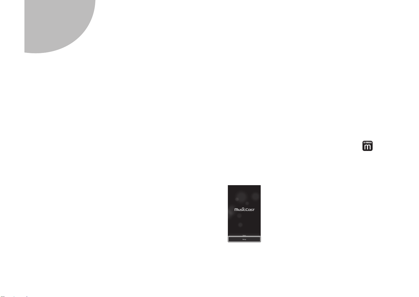
1 Install the MusicCast CONTROLLER app on
your mobile device, and open the app.
Search for “MusicCast CONTROLLER” on the App Store or Google Play.
2 Tap “Setup”.
12 En
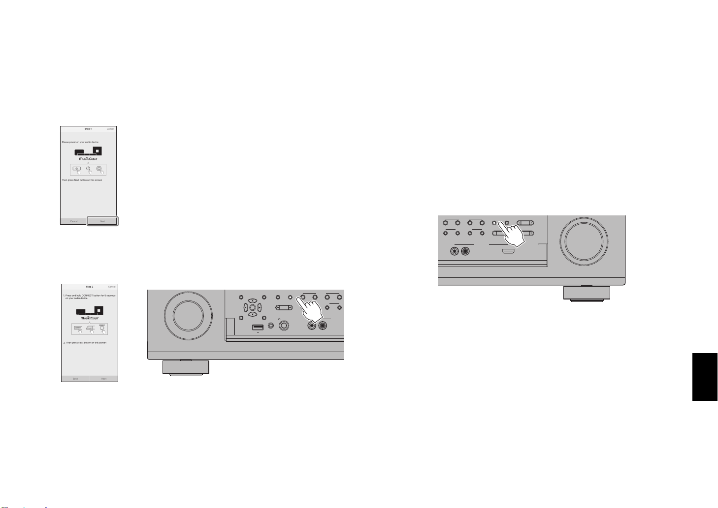
3 Confirm that the unit is turned on, and tap “Next”.
X
4 Press and hold the CONNECT button on the front
panel of the unit for 5 seconds, as instructed by
the app.
TONE CONTROL
STRAIGHT
ON SCREEN
OPTION
PROGRAM
ENTER
DISPLAYRETURN
PHONES
USB
SILENT CINEMA
YPAO MIC
5V
1A
(
)
CONNECT
ZONE 2
SCENE
1234
MULTI ZONE
ZONE 3
ZONE 4
RL AUDIO
ZONE CONTROL
VIDEO AU
5 Follow the app’s on-screen instructions to
configure network settings.
When a connection has been established, “Completed” will be displayed
in the front display of the unit.
Network connection with the MusicCast CONTROLLER app is now complete,
and the unit has been registered as a MusicCast-enabled device.
B Using WPS push-button
configuration
Wireless connection can be configured with one push of the WPS button on
the wireless router (access point).
1 Press and hold INFO (WPS) on the unit’s front
panel for more than 3 seconds.
)
SCENE
1234
MULTI ZONE
ZONE 2
ZONE 3
“Press WPS button on Access Point” will be displayed in the front display.
INFO (WPS
MEMORY
PRESET
FM AM
ZONE 4
ZONE CONTROL
VIDEO AUX
RL AUDIO
TUNING
HDMI IN
2 Push the WPS button on the wireless router.
When a connection has been established, “Completed” will be displayed
in the front display.
Note
If “Not connected” is displayed, repeat the process from step 1 or try another
connection method.
En 13
Optimizing the speaker settings automatically
YPAO MIC
12
3
9
54
ER
ENTER
RETURN
POP-UP/MENU
TOP MEN U
INPUT
MUTE
TV VOL TV CH
TV
4321
8765
9 0
41 2 3
MUTE
OPTION
ON
SCREEN
DISPLAY
MODE
MOVIE MUSIC
INFO SLEEP
ENT
PRESETTUNING
VOLUME
PROGRAM
BAND
SUR. DECODE
STRAIGHT
ENHANCER PURE DIRECT
10
MEMORY
CODE SET
RETURN
U
T
U
INPUT
MU
O
T
3
865
9
0
4
E
T
G
E
T
CT
Y
T
ENTER
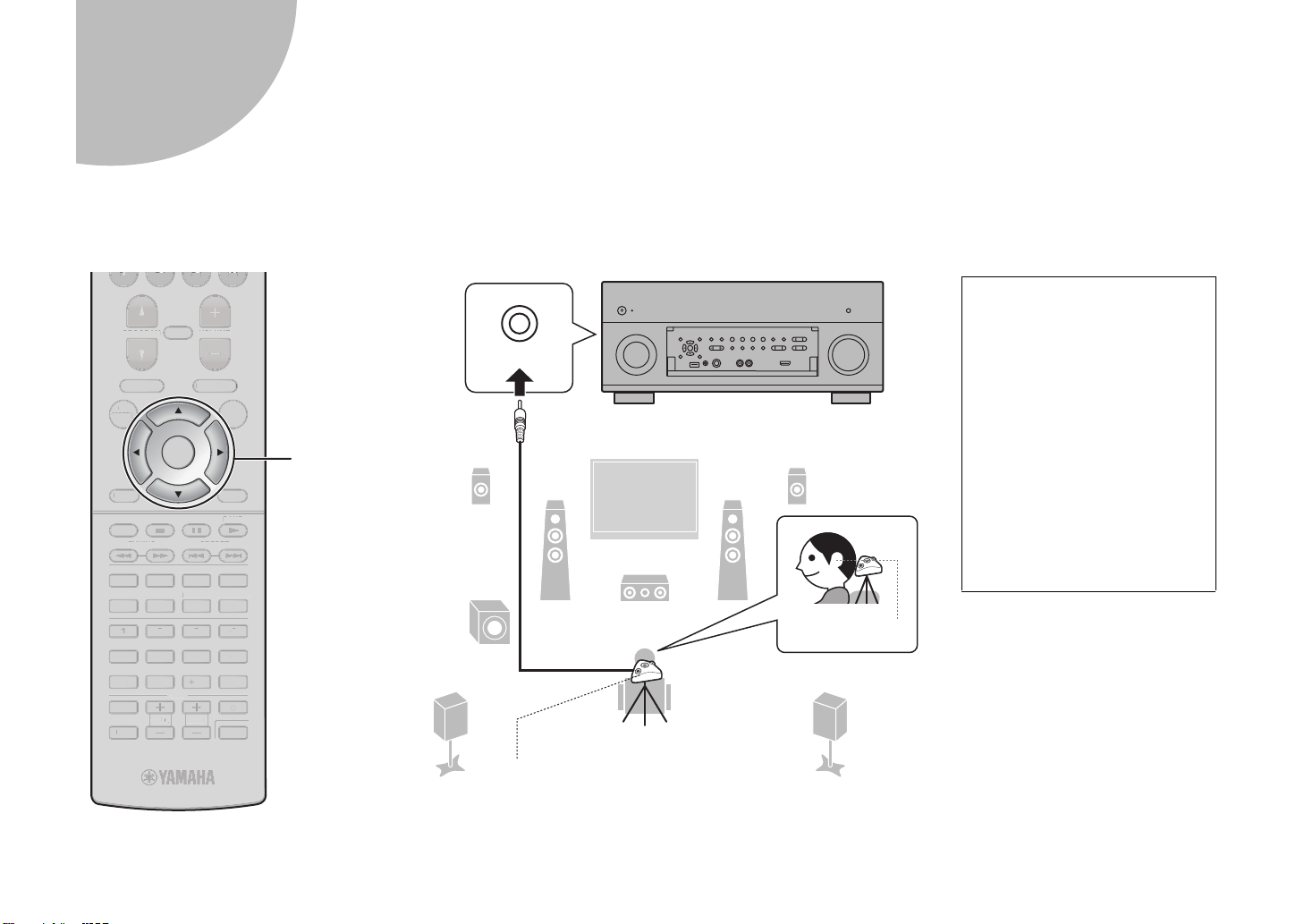
Note the following regarding
YPAO measurement
• Test tones are output at high
volume and may surprise or
frighten small children.
• Test tone volume cannot be
adjusted.
• Keep the room as quiet as
possible.
• Stay in a corner of the room
behind the listening position
so that you do not become an
obstacle between speakers
and the YPAO microphone.
• Do not connect headphones.
Ear height
Listening position
YPAO microphone
Cursor keys
8
(YPAO)
The Yamaha Parametric room Acoustic Optimizer (YPAO) function detects speaker connections, measures the distances from them to your listening position(s),
and then automatically optimizes the speaker settings, such as volume balance and acoustic parameters, to suit your room.
T
LUME
POP-UP/MEN
OPTION
ROGRAM
N
REEN
OP MEN
RESE
STRAIGH
UR. DECOD
ENHANCER
MEMOR
V CH
ISPLAY
RE DIRE
DE SE
DE
NIN
OVIE MUSIC
NFOLEEP
TE
14 En
 Loading...