

Page 1
Multitrack Cassette Recorder
User’s Guide
Manuel de l’utilisateur
Bedienungsanleitung
Guía del Usuario
HIGH
–+
LOW
–+
AUX
010
PAN
LR
10
9
8
7
6
5
4
3
2
1
0
1
GAIN
MIC/LINE
HIGH
+6
+3
0
LOW
-5
-10
AUX
REC
REC
SEL
1
OFF
L
PAN
CUE
10
10
0
MIC
LINE
LR
STEREO OUT
+6
–+
–+
9
8
7
6
5
4
3
2
1
0
+3
-5
-10
REC
SEL
2
OFF
010
R
CUE
LR
10
0
GAIN
MIC
LINE
2
MIC/LINE
LR
MONITOR OUT
HIGH
–+
0
LOW
–+
AUX
REC
010
PAN
LR
10
9
8
7
6
5
4
3
2
1
0
3
+6
+3
0
-5
-10
REC
SEL
3
OFF
L
CUE
10
0
GAIN
MIC
LINE
MIC/LINE
REC
SYNC OUT AUX SEND L (MONO) R
HIGH
–+
LOW
–+
AUX
PAN
10
9
8
7
6
5
4
3
2
1
0
+6
+3
0
-5
-10
REC
REC
SEL
4
OFF
010
R
CUE
LR
10
0
GAIN
MIC
LINE
4
MIC/LINE
ZERO STOP
OFF ON
AUX RETURN
AUX RETURN
0 10
SYNC OFF ON
NOISE REDUCTION SYSTEM
POWER MONITOR/PHONES
MONITOR SELECT
STEREO MIX CUE
PITCH
–
000
PLAY REW FF STOP PAUSEREC
MIN MAX
+
MULTITRACK CASSETTE RECORDER
PUSH OPEN
Page 2

FCC INFORMATION (U.S.A.)
1. IMPORTANT NOTICE: DO NOT MODIFY THIS UNIT!
This product, when installed as indicated in the instructions contained
in this manual, meets FCC requirements. Modifications not expressly
approved by Yamaha may void your authority, granted by the FCC, to
use the product.
2. IMPORTANT: When connecting this product to accessories and/or
another product use only high quality shielded cables. Cable/s
supplied with this product MUST be used. Follow all installation
instructions. Failure to follow instructions could void your FCC
authorization to use this product in the USA.
This applies only to products distributed by YAMAHA CORPORATION OF
*
AMERICA.
Dette apparat overholder det gaeldende EF-direktiv vedtrørende
radiostøj.
Cet appareil est conforme aux prescriptions de la directive
communautaire 87/308/CEE.
Diese Geräte entsprechen der EG-Richtlinie 82/499/EWG und/
oder 87/308/EWG.
This product complies with the radio frequency interference
requirements of the Council Directive 82/499/EEC and/or 87/308/
EEC.
Questo apparecchio è conforme al D.M.13 aprile 1989 (Direttiva
CEE/87/308) sulla soppressione dei radiodisturbi.
Este producto está de acuerdo con los requisitos sobre interferencias
de radio frequencia fijados por el Consejo Directivo 87/308/CEE.
YAMAHA CORPORATION
Page 3

i
Precautions
Read through the following precautions before operating your MT50.
Safety precautions
• Make sure the AC adaptor’ s cord is not located in a position where it is
likely to be walked on or pinched by other equipment.
• Do not expose the MT50 to direct sunlight, extremes of temperature,
humidity, dust, vibration, or severe shocks.
• The ambient temperature where the MT50 is located should be between
10˚C and 35˚C (50˚F and 95˚F).
• Use only the AC adaptor supplied with the MT50. Do not use another
manufacturer’s A C adaptor.
• The AC adaptor should be connected only to an AC power outlet of the
type stated on the AC adaptor or in this User’s Guide.
• Before connecting the AC adaptor to the MT50, disconnect the adaptor
from the AC outlet. Always connect the AC adaptor to the MT50, then
plug the AC adaptor into the AC outlet.
• Grip the plug of the AC adaptor firmly when removing it from an AC
outlet. Do not pull the adaptor’s cord.
Handling precautions
• To reduce the risk of electric shock, do not open the MT50.
• To reduce the risk of fire or electric shock, do not expose the MT50 to
rain or moisture.
• In an extremely humid environment, condensation may form on the
inside and outside of the MT50. If condensation does occur, leave the
MT50 powered on, but do not use it until the condensation has cleared.
Maintenance
• Use a soft, dry cloth to clean the MT50.
• If the MT50 should require more thorough cleaning, use a soft, lightly
moistened cloth. Stubborn marks can be removed using a mild detergent. Do not use abrasive or solvent based cleaners such as alcohol and
benzine.
Service and repair
• Refer all servicing to qualified personnel.
• If any of the following incidents occur , the MT50 should be serviced by
qualified personnel:
The AC adaptor’s cord or plug is damaged.
Metal objects or liquids get inside the MT50.
The MT50 is exposed to rain.
The MT50 is dropped or the enclosure is damaged.
The MT50 does not operate normally or you notice a marked change in
performance.
© 1994 Yamaha Corporation. All rights reserved.
All trademarks are the property of their respective holders.
MT50 User’s Guide
Page 4

ii
Contents
1 Welcome to the MT50 . . . . . . . . . . . . . . . . 1
About this User’s Guide . . . . . . . . . . . . . . . . . . . . . . . . . . 1
What is the MT50? . . . . . . . . . . . . . . . . . . . . . . . . . . . . . . 1
Choosing Cassette Tapes . . . . . . . . . . . . . . . . . . . . . . . . . 1
About Multitrack Recording . . . . . . . . . . . . . . . . . . . . . . 2
Are Four Tracks Enough? . . . . . . . . . . . . . . . . . . . . . . . . 2
A Few Suggestions . . . . . . . . . . . . . . . . . . . . . . . . . . . . . . 2
2 Getting to Know the MT50 . . . . . . . . . . . 3
Connections . . . . . . . . . . . . . . . . . . . . . . . . . . . . . . . . . . . 7
3 Basic Recording . . . . . . . . . . . . . . . . . . . . 8
Loading Cassettes into the MT50 . . . . . . . . . . . . . . . . . . 8
Power ON/OFF . . . . . . . . . . . . . . . . . . . . . . . . . . . . . . . . 8
Preparation . . . . . . . . . . . . . . . . . . . . . . . . . . . . . . . . . . . . 8
Step 1 — Recording the Drums . . . . . . . . . . . . . . . . . . . . 9
Step 2 — Recording the Bass . . . . . . . . . . . . . . . . . . . . . 10
Step 3 — Recording the Guitar . . . . . . . . . . . . . . . . . . . 11
Step 4 — Recording the Vocals . . . . . . . . . . . . . . . . . . . 12
Step 5 — Mixing Down . . . . . . . . . . . . . . . . . . . . . . . . . 13
Preparation . . . . . . . . . . . . . . . . . . . . . . . . . . . . . . . . . . . 13
Balancing Levels . . . . . . . . . . . . . . . . . . . . . . . . . . . . . . 13
Panning . . . . . . . . . . . . . . . . . . . . . . . . . . . . . . . . . . . . . . 14
Applying EQ . . . . . . . . . . . . . . . . . . . . . . . . . . . . . . . . . 14
Adding Effects . . . . . . . . . . . . . . . . . . . . . . . . . . . . . . . . 14
Mixdown Recording . . . . . . . . . . . . . . . . . . . . . . . . . . . . 14
Setting example . . . . . . . . . . . . . . . . . . . . . . . . . . . . . . . 15
ProMix 01 User’s Guide
4 Advanced Recording . . . . . . . . . . . . . . . 16
One-Take Recording . . . . . . . . . . . . . . . . . . . . . . . . . . . 16
Ping-Pong Recording . . . . . . . . . . . . . . . . . . . . . . . . . . . 16
Punch-In/Out Recording . . . . . . . . . . . . . . . . . . . . . . . . 16
Synchronization . . . . . . . . . . . . . . . . . . . . . . . . . . . . . . . 16
One-Take Recording . . . . . . . . . . . . . . . . . . . . . . . . . . . 17
Ping-Pong Recording . . . . . . . . . . . . . . . . . . . . . . . . . . . 21
Punch In/Out Recording . . . . . . . . . . . . . . . . . . . . . . . . . 23
Synchronization . . . . . . . . . . . . . . . . . . . . . . . . . . . . . . . 25
Appendix . . . . . . . . . . . . . . . . . . . . . . . . . 26
Troubleshooting . . . . . . . . . . . . . . . . . . . . . . . . . . . . . . . 26
MT50 Maintenance . . . . . . . . . . . . . . . . . . . . . . . . . . . . 27
Specifications . . . . . . . . . . . . . . . . . . . . . . . . . . . . . . . . . 29
General Specifications . . . . . . . . . . . . . . . . . . . . . . . . 29
Block Diagram . . . . . . . . . . . . . . . . . . . . . . . . . . . . . 30
Dimensions . . . . . . . . . . . . . . . . . . . . . . . . . . . . . . . . 30
Glossary . . . . . . . . . . . . . . . . . . . . . . . . . . 31
Page 5
1
• Standard Cassette Deck
B side Track 1 L channel
B side Track 2 R channel
A side Track 2 L channel
A side Track 1 R channel
• MT50
Transport
direction
Transport
direction
Welcome to the MT50
Welcome to the MT50
Thank you for choosing the Yamaha MT50 Multitrack Cassette Recorder.
The MT50 is an easy-to-use four-track cassette tape recorder that will allow
you to capture your music at a very high level of quality. To take best advantage of the MT50‘s multitrack features, please read this manual thoroughly.
About this User’s Guide
This User’s Guide consists of four main chapters.
• Chapter 1: Welcome to the MT50
• Chapter 2: Getting to Know the MT50
• Chapter 3: Basic Recording
• Chapter 4: Advanced Recording
“Chapter 2: Getting to Know the MT50” explains the MT50’ s controls and
connections. “Chapter 3: Basic Recording” explains basic setup and the
power-on procedure and contains a step-by-step tutorial for ov erdub recording and mixdown. “Chapter 4: Advanced Recording” explains some
advanced MT50 recording techniques, such as one-take recording,
ping-pong recording, punch in/out recording, and MIDI tape synchronization.
If you’re new to the world of multitrack recording, read Chapter 2 thoroughly. The Appendix provides technical information and a glossary.
1
Track 4:
Track 3:
Track 2:
Track 1:
* dbx noise reduction system was manu-
factured based on a patent license fr om
THAT Corporation.
dbx is a trademark of Carillon Electronics Corporation..
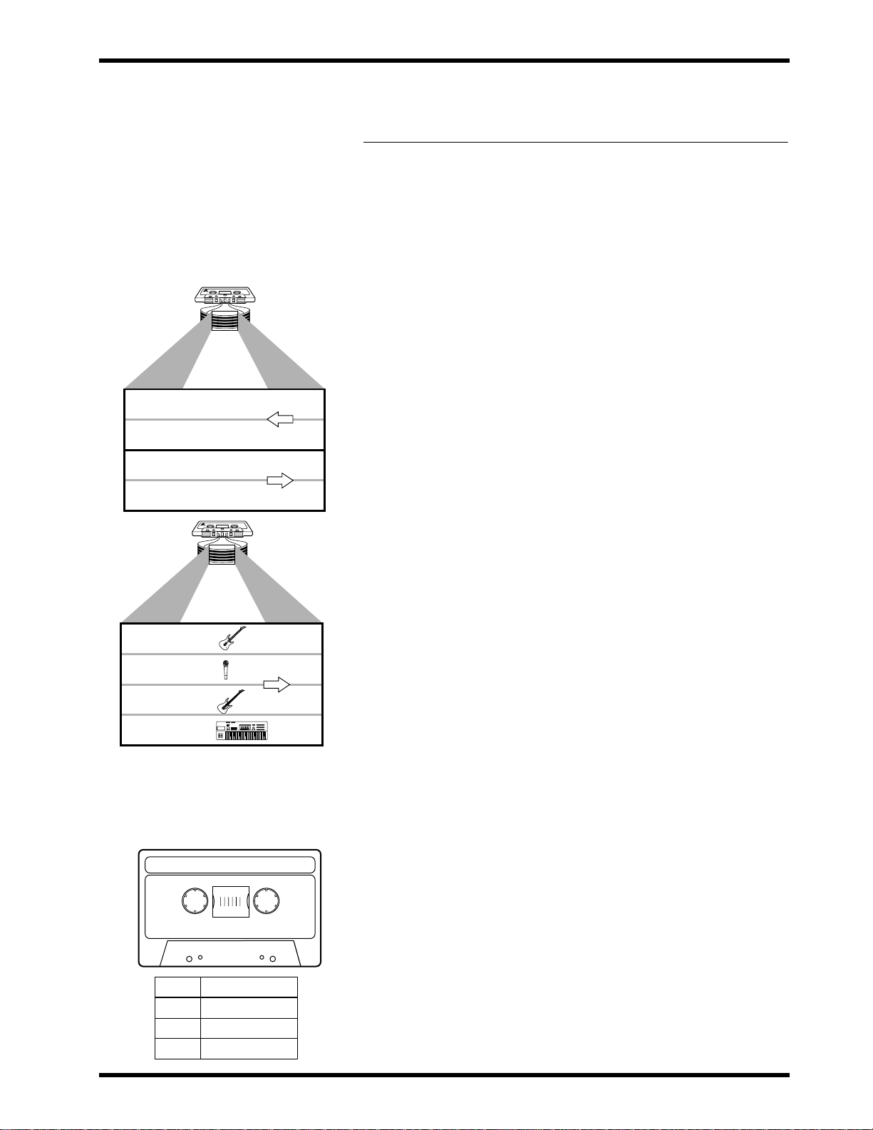
High-position (Chrome, type II),
Less than 90 minutes
High Bias 70µs EQ
Tape Rec.Time
90 min. Approx. 22.5 min.
60 min. Approx. 15 min.
30 min. Approx. 7.5 min.
Transport
direction
What is the MT50?
A standard hi-fi cassette recorder uses only two tracks (i.e., left and right)
and both tracks are recorded simultaneously. The MT50, on the other hand,
can record four tracks on a standard audio cassette. Even more importantly ,
you can record and play back these four tracks individually . You can record
all four tracks simultaneously, or one at a time (a technique called o v erdub
recording). The MT50 uses only one side of a standard audio cassette; in
effect, there is no B side. If you turn the cassette over, you’ll hear the four
tracks play backwards. This is because the MT50 uses the full width of the
tape to record four tracks. The MT50 uses dbx noise reduction to reduce
tape hiss and keep your recordings clean and crisp. Once you’ve recorded
your four tracks, you can mixdown into stereo using the MT50’s flexible
mixer, with EQ, pan, and an aux send for adding effects.
Choosing Cassette Tapes
For best performance use high-quality Type II (High Bias 70 µ s EQ)
chrome cassettes of 90 minutes or less, such as TDK SA, Maxell UD-XLII,
and Sony UX-S. Do not use metal tapes or 120 minute tapes. At normal
speed a 60-minute cassette provides about 15 minutes of recording time.
That’s because the tape runs at twice the speed of a standard cassette
recorder and you use only side A.
MT50 User’s Guide
Page 6

2
Chapter 1: Welcome to the MT50
About Multitrack Recording
Multitrack recording simply refers to recording on more than one track (a
track is a physical strip on a recording tape). Invented by Les Paul in the
1950’s, multitrack recording constituted a revolutionary breakthrough in
the recording arts. Suddenly, you could record multiple instruments on separate tracks on a tape and mix them together later, making adjustments to
each track independently.
The MT50 gives you this incredible capability in a compact, portable unit
that you can use to make multitrack recordings almost anywhere--at the
rehearsal studio with the band, or in your bedroom. If you combine the
MT50 with other music technologies such as MIDI and digital effects processing, you can make some great-sounding recordings.
Are Four Tracks Enough?
The MT50 is a four-track tape recorder: its recording heads create four separate tracks on a tape.
You will also notice that the left side of the unit is composed of four groups
or “modules” of identical controls. These modules control four separate
mixer channels with faders, tone, pan, and auxiliary send controls.
This combination of four inputs, four mixer channels, and four tracks gives
you an enormous amount of flexibility. You can create a signal that runs
from any input to any track on the tape. (In other words, there is no need to
record input module 1 to track 1 on the tape; input 1 can be routed to tracks
2, 3, or 4.)
Y ou can ov erdub your own recordings, listening to one part while recording
another.
You can also transfer recorded takes from up to three tracks to an unrecorded track. Then you can record over the initial tracks, and perhaps repeat
the process. Using this technique--called ping-pong recording--you can
effectively expand your four track studio into a virtual ten-or-more track
studio!
MT50 User’s Guide
A Few Suggestions
• Avoid rheostats (dimmer switches for electric lights), air conditioners,
and fluorescent or neon lights. They all add hum to your recordings.
• If you use microphones to record, it is helpful to record in a room that
sounds good: in other words, an appropriate acoustic environment.
Also, you can experiment with the placement of your microphones;
minor adjustments can deeply affect the sound quality.
• Use high quality, shielded cables.
• If you have an analog or digital reverb effect unit, you will probably
want to use it. However, use it sparingly. Too much reverb can quickly
muddy your sound. Consider saving reverb until the final mixdown, so
you apply it evenly to the entire mix
Page 7
–+
–+
–+
–+
–+
–+
–+
–+
–
+
000
HIGH
LOW
AUX
PAN
1
OFF
L
REC
SEL
LR
010
CUE
10
0
MIC/LINE
1
10
9
8
7
6
5
4
3
2
1
0
+6
+3
0
-5
-10
REC
HIGH
LOW
AUX
PAN
2
OFF
R
REC
SEL
LR
010
CUE
10
0
MIC/LINE
2
10
9
8
7
6
5
4
3
2
1
0
+6
+3
0
-5
-10
REC
HIGH
LOW
AUX
PAN
3
OFF
L
REC
SEL
LR
010
CUE
10
0
MIC/LINE
3
10
9
8
7
6
5
4
3
2
1
0
+6
+3
0
-5
-10
REC
HIGH
LOW
AUX
PAN
4
OFF
R
REC
SEL
LR
010
CUE
10
0
MIC/LINE
4
10
9
8
7
6
5
4
3
2
1
0
+6
+3
0
-5
-10
REC
LR
STEREO OUT
LR
MONITOR OUT
SYNC OUT AUX SEND L (MONO) R
AUX RETURN
AUX RETURN
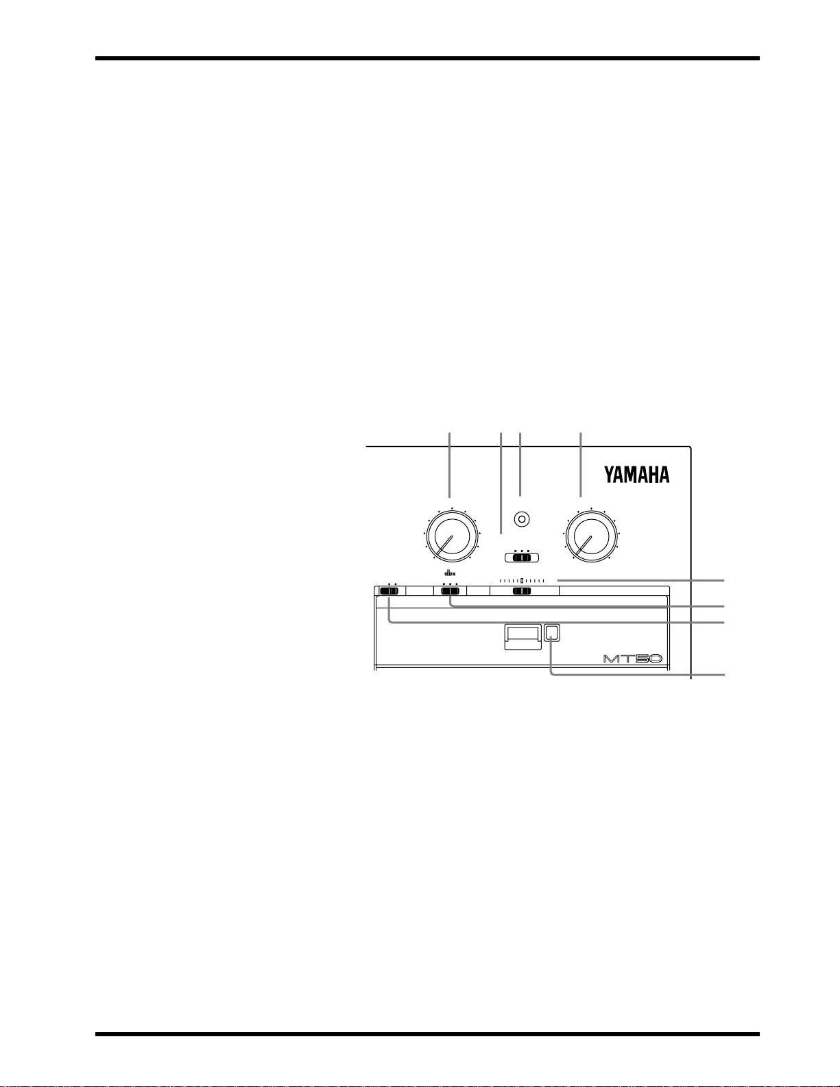
POWER MONITOR/PHONES
MONITOR SELECT
STEREO MIX CUE
PITCH
MIN MAX
ZERO STOP
OFF ON
SYNC OFF ON
MULTITRACK CASSETTE RECORDER
NOISE REDUCTION SYSTEM
PLAY REW FF STOP PAUSEREC
PUSH OPEN
0 10
GAIN
MIC
LINE
GAIN
MIC
LINE
GAIN
MIC
LINE
GAIN
MIC
LINE
2
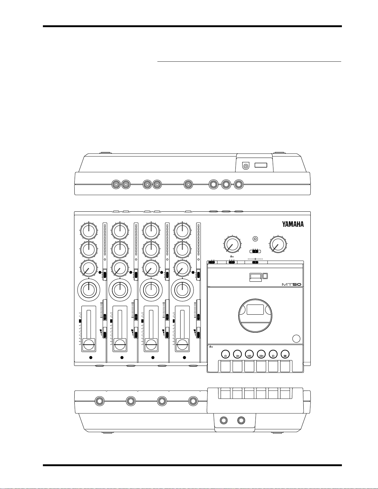
Getting to Know the MT50
Getting to Know the MT50
This chapter takes you on a guided tour of the MT50 and explains what the
controls and connections do, and how to use them.
First the module controls, then the general controls, are illustrated and
explained. Finally, the MT50’s connections are covered. Refer to the illustrations below and throughout this chapter to identify the MT50’s controls
and connections. This will make it easier for you to complete the tutorial in
“Chapter 3: Basic Recording.”
3
MT50 User’s Guide
Page 8
4
Chapter 2: Getting to Know the MT50
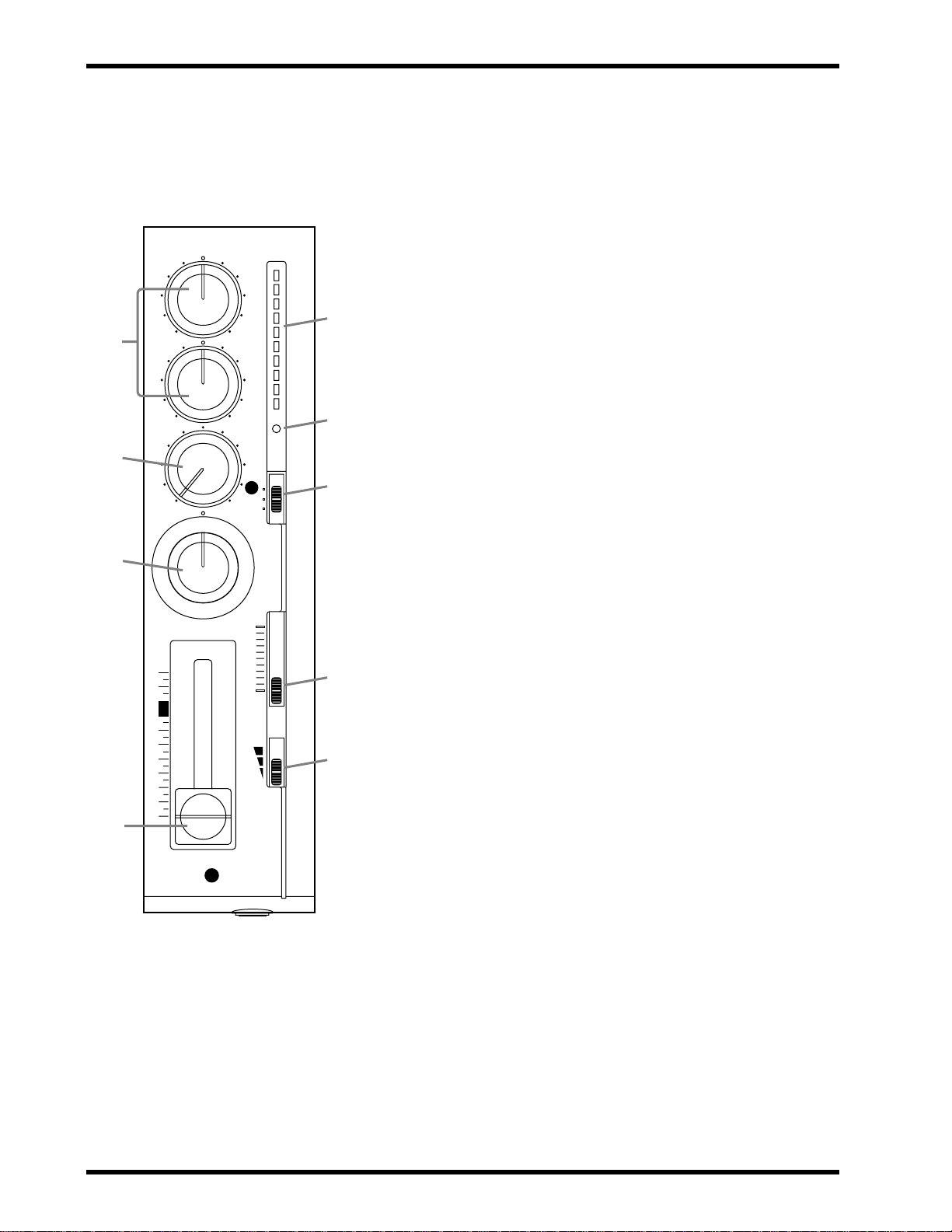
Note: Contr ols 1 thr ough 9 ar e the
same for all four input modules.
1
2
HIGH
– +
LOW
– +
AUX
010
PAN
REC
SEL
OFF
+6
+3
0
-5
-10
REC
1
L
3
5
6
7
HIGH and LOW equalization controls: These controls
1
adjust the tone (EQ). When something is connected to the
MIC/LINE input, these controls affect the tone of the input signal
(i.e., the signal to be recorded). When nothing is connected to the
MIC/LINE input, these controls affect the tone of the playback
signal (i.e., the tape signal fed into the stereo mix).
AUX contr ol: This control sets the level of the signal fed to the
2
AUX SEND output, which is used to feed an e xternal effects processor. The MT50’ s aux send signal is sourced after the f ader . To
feed a channel’s signal to an e xternal effects processor via the aux
send, you must turn up its AUX control and raise its fader.
3
PAN control: This control positions the playback of a sound in
the stereo mix (i.e., between the left and right channels). T urning
to the right pans a signal to the right channel; turning to the left
pans a signal to the left channel. For center position, an equal
amount of signal is fed to both the left and right outputs.
Fader: When something is connected to the MIC/LINE input,
4
the fader sets the recording level (i.e., the le vel of the input signal
recorded to tape). When nothing is connected to the MIC/LINE
input, this fader sets the playback level (i.e., the level of the tape
signal fed to the stereo mix). For best performance, the fader
should be positioned between 7 and 8.
LR
10
9
8
7
6
5
4
3
2
1
0
CUE
10
0
GAIN
MIC
LINE
4
1
MIC/LINE
! For the technically minded, the
HIGH control has a center frequency of 12kHz and the LOW control, 80Hz. Both contr ols offer up to
12dB of cut and boost.
8
9
5
Level meter: This LED meter shows the recording and play-
back level. The recording level should be set so that the +6 LED
lights occasionally at the maximum input level. The f ader sets the
recording level.
REC indicator: This indicator shows the recording mode.
6
Off
— REC SEL switch set to OFF.
Flashing
set to 1, 2, 3, 4, L, or R, in which case the track is ready to record).
Lit
7
REC SEL switch: This switch selects the signal to be recorded.
Off
1 (2, 3, 4)
L (R)
can be recorded to tracks 1 and 3. Right signals can be recorded to
tracks 2 and 4. Use this setting for ping-pong recording.
8
CUE slider: This control sets the CUE level. CUE allo ws you to
— REC SEL switch set to one of the “on” positions (i.e.,
— Recording in progress or recording paused.
— Recording is not active.
— The MIC/LINE input signal is recorded.
— The left (right) stereo mix signal is recorded. Left signals
adjust the volume of the monitor independently of the fader settings. This control is effective only when the MONITOR
SELECT switch is set to either MIX or CUE.
GAIN switch: This switch sets the MIC/LINE input gain for
9
optimum performance, depending on what you connect to the
MIC/LINE input.
MIC
— microphones, low-level devices.
Middle
LINE
— synthesizer, drum machine, CD player , high-lev el devices.
— electric guitar, electric bass.
MT50 User’s Guide
Page 9
Getting to Know the MT50
AUX RETURN contr ol: This control sets the level of the AUX
0
RETURN input signal (i.e., the level of the processed signal from
an external effects processor) back into the stereo mix.
A
MONITOR SELECT switch: This switch determines the sig-
nal source for the PHONES and the MONITOR OUT.
Stereo
Pan control (the level of these signals is adjusted by the faders).
Cue
Use this for overdub recording.
Mix
punch-in/out recording.
POWER indicator: This indicator lights up when the MT50 is
B
— This setting selects the L and R signals controlled by the
— The signal source is CUE (controlled by the CUE sliders).
— The signal source is the stereo mix and CUE. Use this for
powered-on and ready for use.
C
MONITOR/PHONES control: This control is used to adjust
the PHONES and MONITOR OUT levels.
0A C
B
5
AUX RETURN POWER MONITOR/PHONES
MONITOR SELECT
STEREO MIX CUE
ZERO STOP
OFF ON
PITCH slider: This control is used to adjust the tape speed plus
D
0
SYNC OFF ON
10
PITCH
–
000
MULTITRACK CASSETTE RECORDER
MAXMIN
+
or minus 10%. The center position is normal speed (9.5 cm/sec).
In general, set this slider to the center position.
E
dbx switch: “dbx” is a sophisticated noise reduction system
that can help you make cleaner-sounding recordings. This switch
is used to turn the dbx noise reduction ON and OFF. The switch
has three positions:
OFF
— dbx noise reduction is OFF.
— dbx noise reduction is ON for all four tracks.
ON
SYNC
4. Use this setting when track 4 is striped with the FSK signal for
synchronized operation.
Note:
ON or SYNC, make sure that ON or SYNC is used for playback too.
Do not change this setting half way through a recording session.
— dbx noise reduction is ON for tracks 1, 2, and 3, but not
If you recorded a tape with dbx noise reduction set to either
D
E
F
G
MT50 User’s Guide
Page 10
6
Chapter 2: Getting to Know the MT50
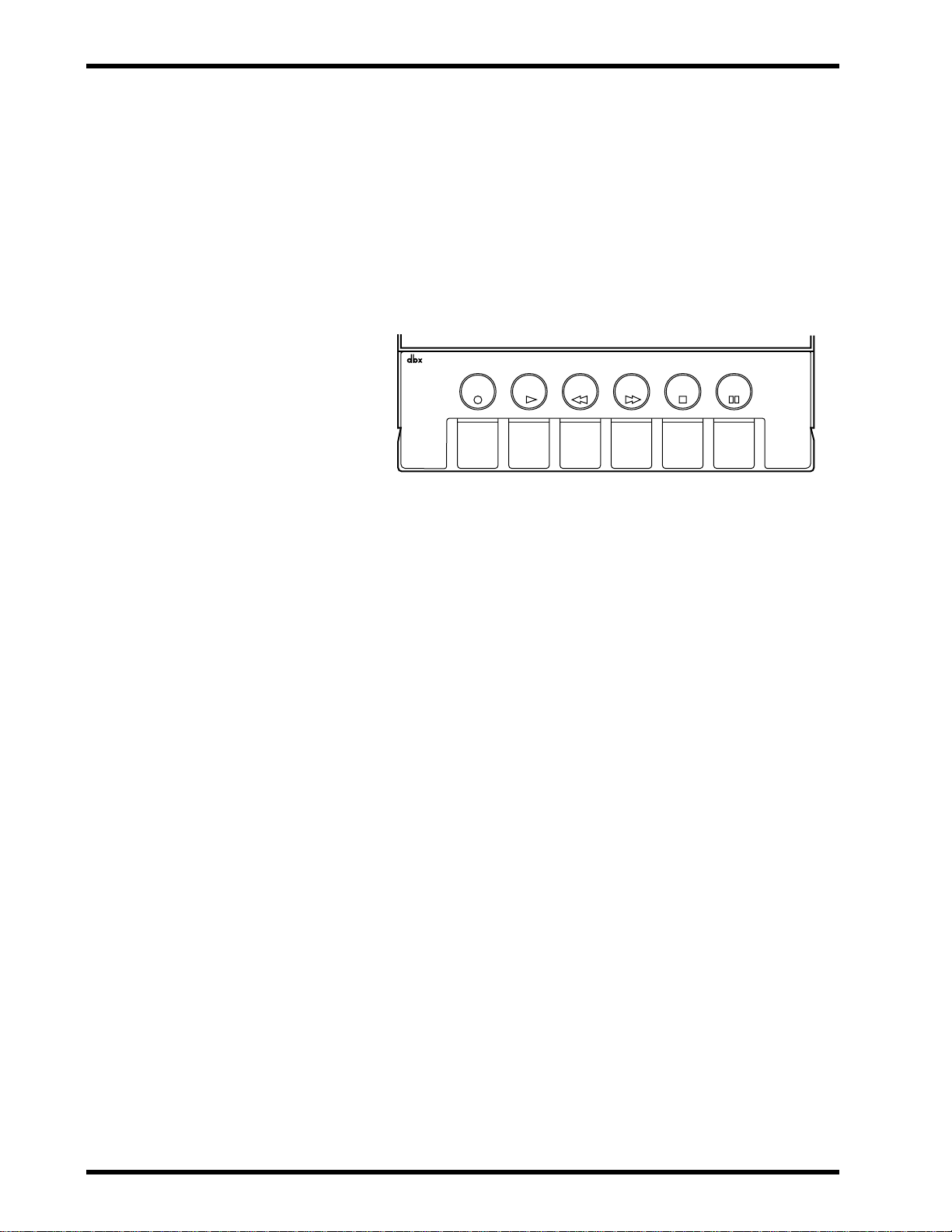
ZERO STOP switch: When set to ON, rewind stops automati-
F
cally at approximately 999 (the REW button remains depressed).
G
Tape counter and reset button: The tape counter indicates
the tape position, making it easy to locate specific points in your
songs. The reset button resets the tape counter to 000.
T ape control buttons: From left to right, their functions are to
H
record (REC); to play back the tape (PLAY); to rewind the tape
(REW); to stop the tape (STOP); and to pause either playback or
recording (PAUSE).
NOISE REDUCTION SYSTEM
PUSH OPEN
PLAY REW FF STOP PAUSEREC
MT50 User’s Guide
Page 11
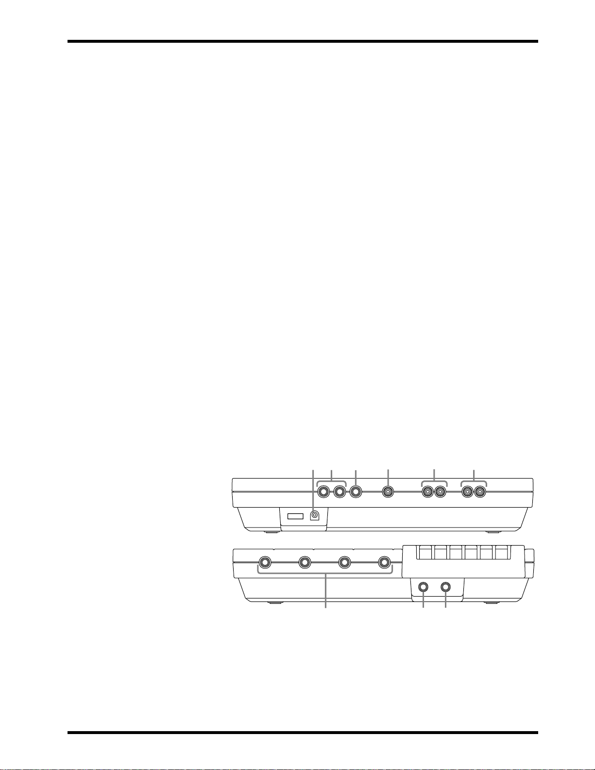
Connections
Connections
1
MIC/LINE input jacks: Microphones, instruments, and
line-level sources are connected here for recording.
2 PHONES jack: A pair of stereo headphones is connected here
to enable you to monitor the recording or playing back of tracks.
3 PUNCH I/O jack: An optional footswitch, such as the Yamaha
FC4 or FC5, is connected here for punch-in/out recording.
4 STEREO OUT jacks: During mix down, signal is output from
these outputs to the master recorder. Connect these outputs to the
inputs of the master recorder.
5 MONITOR OUT jacks: The monitor signal is output from these
L/R jacks. Connect a pair of speakers with built-in amplifiers.
6 SYNC OUT jack: This jack outputs the FSK signal to synchro-
nize the MT50 and a MIDI sequencer or drum machine. Connect
a MIDI-FSK convertor such as the Yamaha YMC10.
7
7 AUX SEND jack: The aux send signal is output at this jack.
Connect this jack to the input on an external effects processor,
such as the Yamaha FX770 or REV100.
8 AUX RETURN jacks: The effects signal is returned here. Con-
nect this to the output on an external effects processor. Use the
L(MONO) input jack for mono return signals. Use both the
L(MONO) and R jacks for stereo return signals.
9 DC 12V POWER connector: Connect the AC adaptor here.
9
8
7
6
5
4
231
MT50 User’s Guide
Page 12
8 Chapter 3: Basic Recording
3
Basic Recording
This chapter explains how to perform overdub recording. Overdub recording is the basis of all multi-track recording. It enables you to record
track-by-track, while listening to previously recorded tracks. In the following example, we will use a drum machine, bass, guitar, and v ocals. You can,
of course, use any instruments you prefer.
Here’s our track list.
Track # Instrument Other Info
1 Drums RYZZ drum machine. Song #10 “I love you”
2 Bass Dave’s bass with chorus effects pedal
3 Guitar My strat through marsh-ball amp
4 Vocal Sandra with FM58 microphone
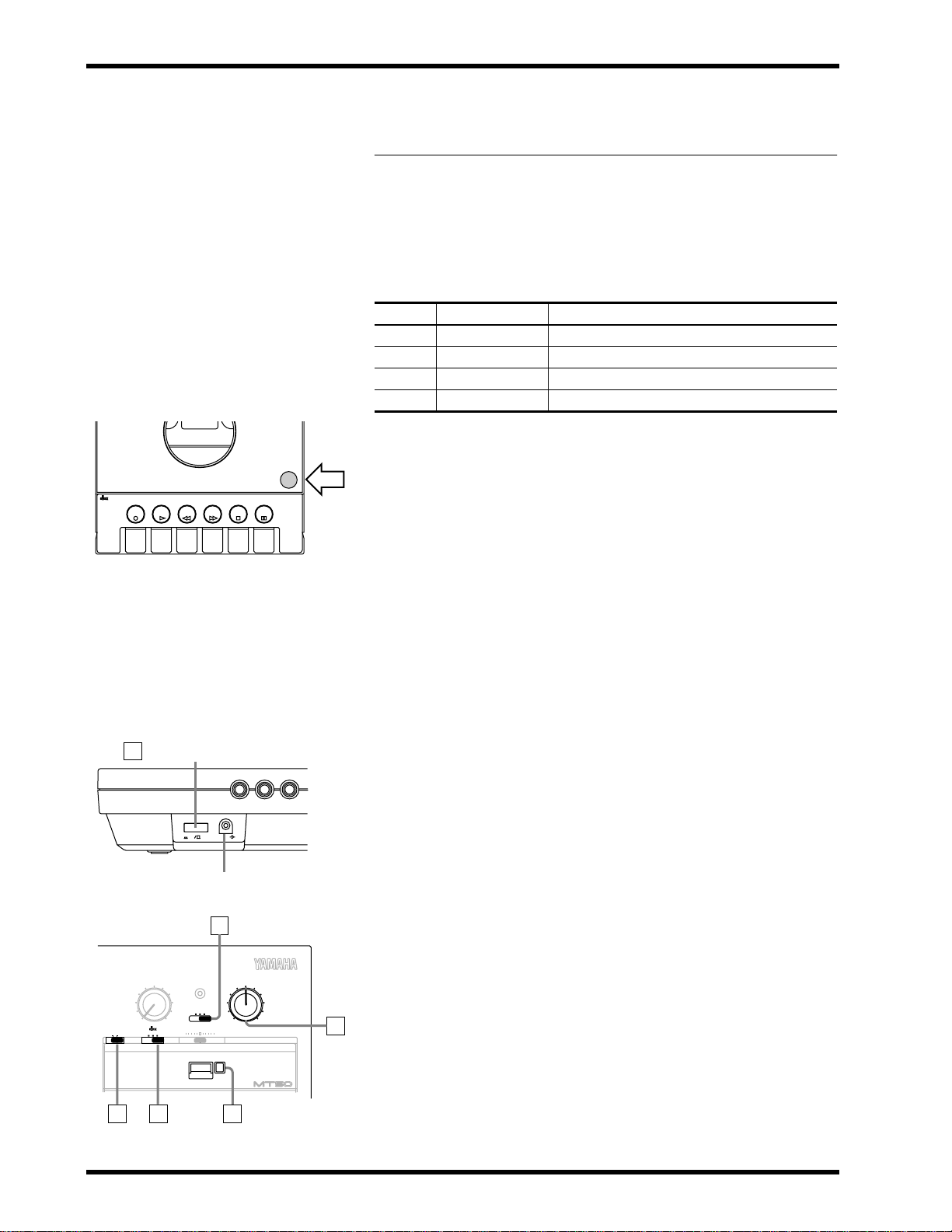
Loading Cassettes into the MT50
NOISE REDUCTION SYSTEM
PLAY REW FF STOP PAUSEREC
PUSH OPEN
! Warning: Before making any
connections, power OFF all your
equipment.
! Warning: The AC adaptor
should be connected only to an AC
outlet of the voltage type stated on
the adaptor.
POWER Switch
1
–
+
DC12Vconnector
2
1. Carefully insert the cassette.
2. Connect the supplied AC adaptor to the DC 12V connector.
3. Plug the AC adaptor into a suitable AC outlet.
4. Connect a pair of stereo headphones to the PHONES jack, or connect the MONITOR OUT to speakers with built-in amps.
Power ON/OFF
1. Press the POWER switch to power ON the MT50.
The POWER indicator lights up.
Preparation
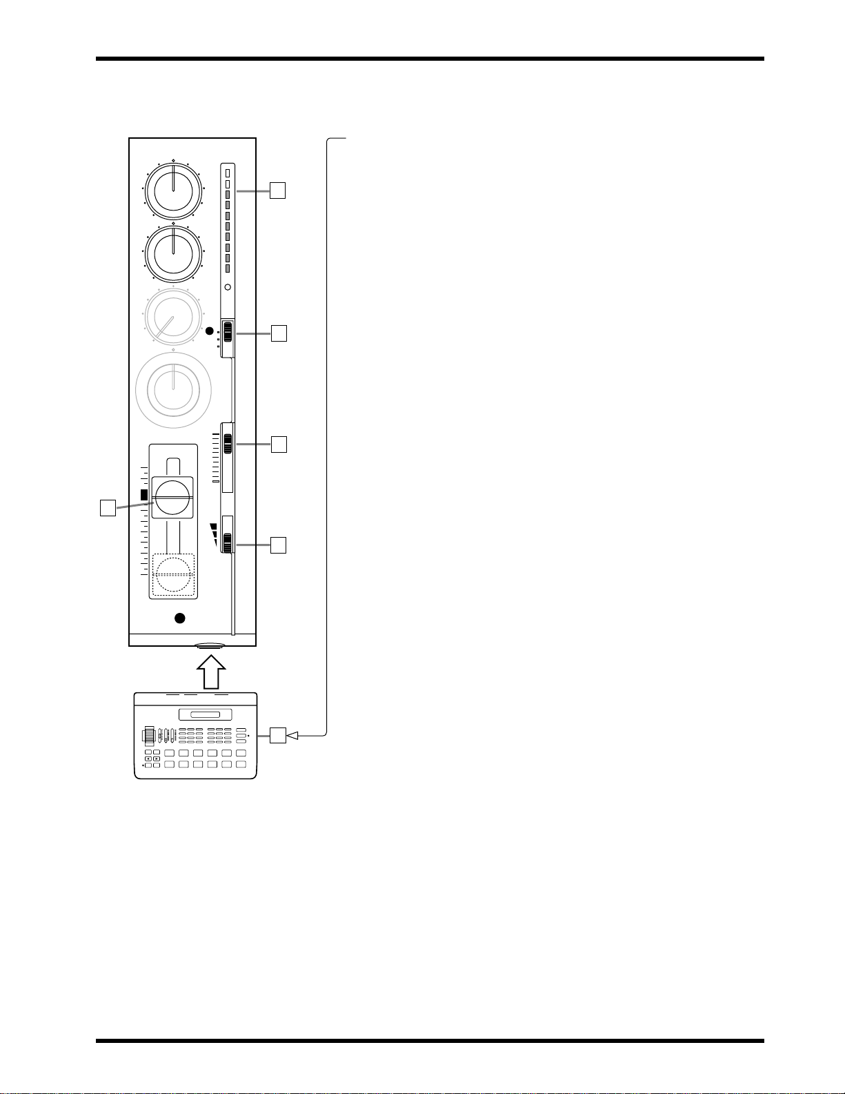
2. Set the MONITOR SELECT switch to CUE.
3. Set the MONITOR/PHONES control to about halfway. You can
always readjust later.
4. Press the reset button to reset the tape counter to 000.
5. Set the ZERO STOP switch to ON.
6. Set the dbx switch to ON.
AUX RETURN POWER MONITOR/PHONES
0
ZERO STOP
OFF ON
MT50 User’s Guide
10
SYNC OFF ON
MONITOR SELECT
STEREO MIX CUE
PITCH
–
+
000
MULTITRACK CASSETTE RECORDER
Reset Button
45 6
MAXMIN
3
Page 13
HIGH
+6
9
4
– +
LOW
– +
AUX
010
PAN
LR
OFF
CUE
10
-10
REC
SEL
1
+3
0
-5
REC
L
3
10
9
8
7
6
8
5
4
3
2
1
0
1
0
GAIN
MIC
LINE
MIC/LINE
2
1
Drum Machine
! The easiest song to recor d is one
that starts with a drum intro. If your
song starts with drums, bass, and
synth all on the first bar , you’ll need
to record a count-in.
Step 1 — Recording the Drums 9
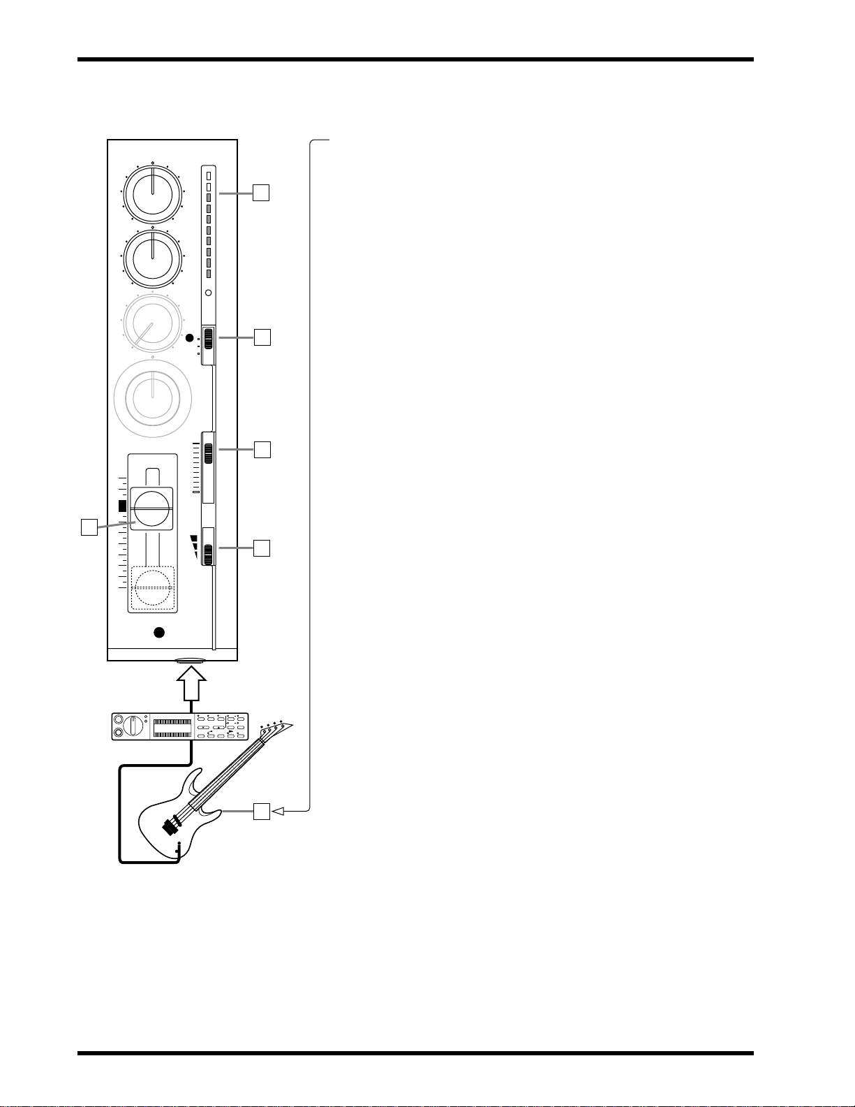
Step 1 — Recording the Drums
1. Connect the drum machine to MIC/LINE input 1.
2. Set Module 1’s GAIN switch to LINE.
3. Set Module 1’s CUE slider to about 8.
4. Set Module 1’s REC SEL switch to 1.
The REC indicator starts flashing.
5. Press the PAUSE button.
6. Press the REC button.
The REC indicator lights up.
7. Start the drum machine
8. Raise Module 1’s fader gradually.
You should be able to hear the drum machine and Module 1’s level
meter should light up.
9. Set the fader so that the +6 light comes on occasionally at the max-
imum input level.
Note: If the drum machine volume is very low you can not achieve the opti-
mum recor ding level with the maximum fader setting, set the fader to 0, and
set the GAIN switch to the middle position (for instruments). Raise the fader
again and set as appropriate.
The module fader is used to set the recording level and should be set in conjunction with the level meter. Use the CUE slider and MONITOR/PHONES control to adjust the monitoring levels. These controls
affect only the monitor signals.
10.Press the PAUSE button to start recording.
11.Start the drum machine.
12.When the drum part is finished, press STOP to stop recording.
13.Press REW to rewind the tape.
It will stop automatically at approximately 999, because we set ZERO
STOP to ON.
14.Set Module 1’s REC SEL switch to OFF.
The REC indicator goes off.
15.Press PLAY to listen to the drum track.
If you like the track, go to “Step 2 — Recording the Bass” once you finish this procedure. If you don’t like it, re-record it.
16.Disconnect the drum machine.
17.Set Module 1’s fader to 0.
18.Press REW to rewind the tape to 000.
MT50 User’s Guide
Page 14
10 Chapter 3: Basic Recording
HIGH
+6
9
4
3
2
1
8
– +
LOW
– +
AUX
010
PAN
LR
10
9
8
7
6
5
4
3
2
1
0
2
Bass Effect
Processor
YAMAHA
FX550B
+3
0
-5
-10
REC
SEL
2
OFF
R
CUE
10
0
GAIN
MIC
LINE
MIC/LINE
REC
Step 2 — Recording the Bass
1. Connect the bass to MIC/LINE input 2.
Note: Connecting an instrument with a high output impedance such as an
electric guitar or bass to the MT50 may increase noise and distortion and
preclude high quality recordings.
If this happens, connect a direct box or effect unit between the instrument
and the MT50 to reduce the impedance.
2. Set Module 2’s GAIN switch to LINE.
3. Set Module 2’s CUE slider to about 8.
4. Set Module 2’s REC SEL switch to 2.
The REC indicator starts flashing.
5. Press the PAUSE button.
6. Press the REC button.
The REC indicator lights up.
7. While strumming the bass, raise Module 2’s fader gradually.
You should be able to hear the bass and the level meter should light up.
8. Set the fader so that the +6 light is on occasionally at the maximum
input level.
9. In order to set the CUE levels, press the PAUSE button to start
recording. (This is only a temporary recording.)
10.While listening to the drum track, play the bass and set Module 1
and 2’s CUE sliders so that you can hear the drums and bass clearly.
11.Press REW to rewind the tape to 000.
12.Press the REC button to start recording.
The REC indicator lights up.
13.Play your bass part while listening to the drum track.
14.When your bass part is finished, press STOP to stop recording.
15.Press REW to rewind the tape to 000.
16.Set Module 2’s REC SEL switch to OFF.
The REC indicator goes off.
17.Press PLAY to listen to the drum track and new bass track.
If you like the track, go to “Step 3 — Recording the Guitar” once you
finish this procedure. If you don’t like it, re-record it.
18.Disconnect the bass.
19.Set Module 2’s fader to 0.
20.Press REW to rewind the tape to 000.
MT50 User’s Guide
Page 15
HIGH
– +
LOW
– +
AUX
010
PAN
LR
10
9
8
7
6
8
5
4
3
2
1
0
3
Guitar Effect Processor
FX770
+6
+3
0
-5
-10
REC
SEL
3
OFF
L
CUE
10
0
GAIN
MIC
LINE
MIC/LINE
REC
Step 3 — Recording the Guitar 11
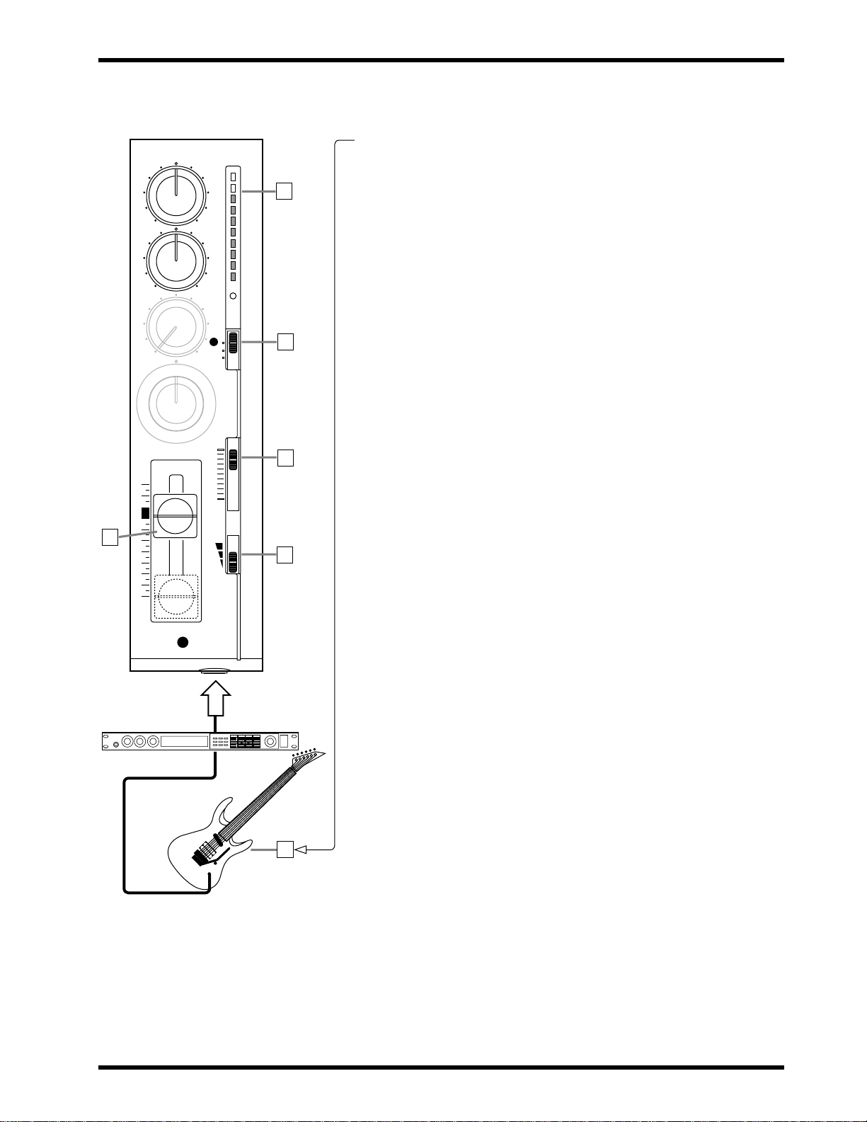
Step 3 — Recording the Guitar
1. Connect the guitar to MIC/LINE input 3.
Note: Connecting an instrument with a high output impedance such as an
9
4
3
2
1
electric guitar or bass to the MT50 may increase noise and distortion and
preclude high quality recordings.
As explained in Step 1 on page 10, connect a direct box or effect unit
between the instrument and the MT50 to reduce the impedance.
2. Set Module 3’s GAIN switch to LINE.
3. Set Module 3’s CUE slider to about 8.
4. Set Module 3’s REC SEL switch to 3.
The REC indicator starts flashing.
5. Press the PAUSE button.
6. Press the REC button.
The REC indicator lights up.
7. While strumming the guitar, raise Module 3’s fader gradually.
Y ou should be able to hear the guitar and the le vel meter should light up.
8. Set the fader so that the 0 light is on most of the time and the +6 light
comes on occasionally.
9. In order to set the CUE levels, press the PAUSE button to start
recording. (This is only a temporary recording.)
10.While listening to the drum and bass tracks, play the guitar and set
Module 1, 2, and 3’s CUE sliders so that you can hear the drums,
bass, and guitar clearly.
11.Press REW to rewind the tape to 000.
12.Press the REC button to start recording.
The REC indicator lights up.
13.Play your guitar part while listening to the drum and bass tracks.
14.When your guitar part is finished, press STOP to stop recording.
15.Press REW to rewind the tape to 000.
16.Set Module 3’s REC SEL switch to OFF.
The REC indicator goes off.
17.Press PLAY to listen to the drum track, bass track, and new guitar
track.
If you like the track, go to “Step 4 — Recording the Vocals” once you
finish this procedure. If you don’t like it, re-record it.
18.Disconnect the guitar.
19.Set Module 3’s fader to 0.
20.Press REW to rewind the tape to 000.
MT50 User’s Guide
Page 16
12 Chapter 3: Basic Recording
HIGH
+6
9
4
3
2
Compressor
1
8
– +
LOW
– +
AUX
010
PAN
LR
10
9
8
7
6
5
4
3
2
1
0
4
YAMAHA
+3
0
-5
-10
REC
SEL
4
OFF
R
CUE
10
0
GAIN
MIC
LINE
MIC/LINE
REC
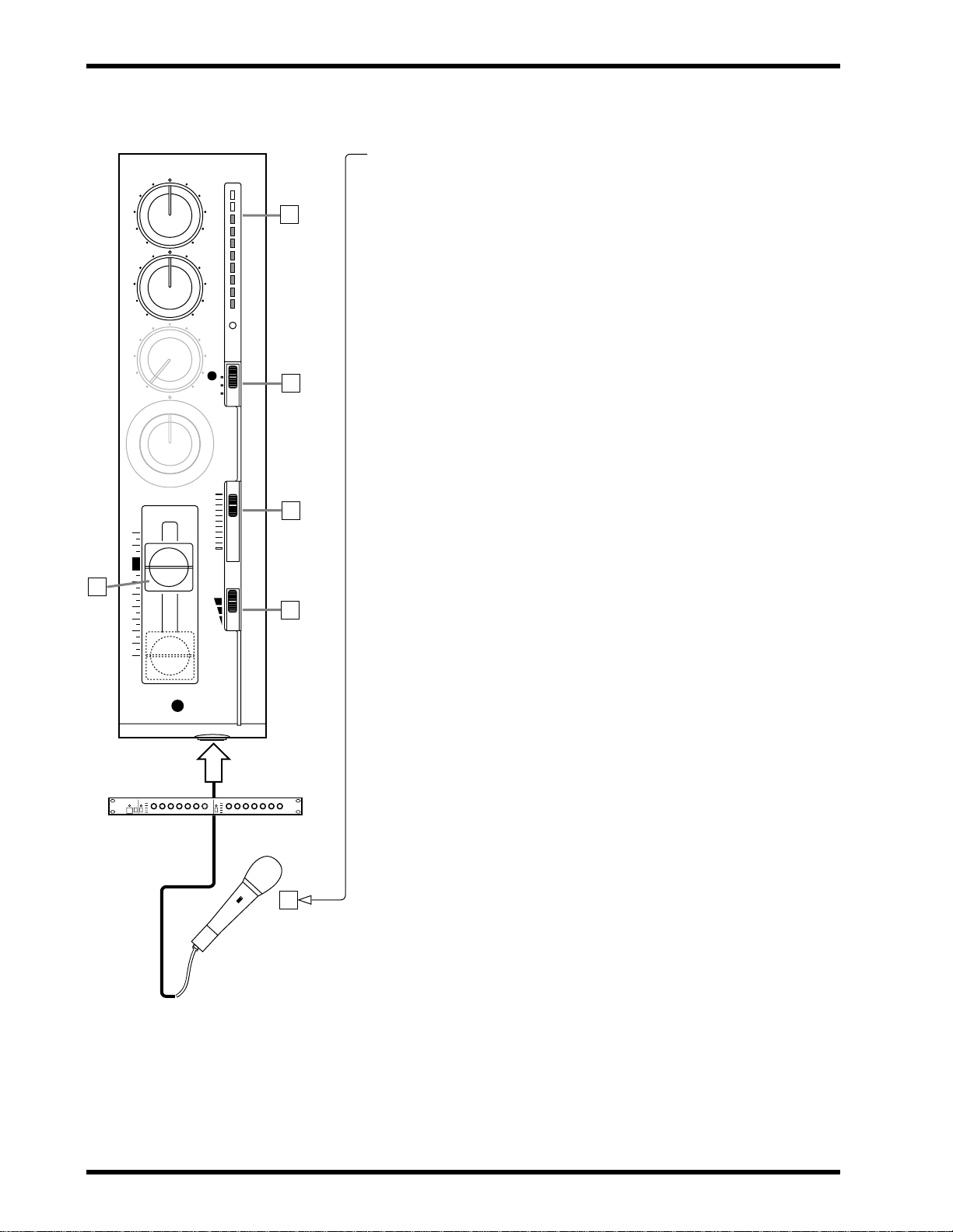
Step 4 — Recording the Vocals
1. Connect the microphone to MIC/LINE input 4.
2. Set Module 4’s GAIN switch to MIC.
3. Set Module 4’s CUE slider to about 8.
4. Set Module 4’s REC SEL switch to 4.
The REC indicator starts flashing.
5. Press the PAUSE button.
6. Press the REC button.
The REC indicator lights up.
7. While singing into the microphone, raise Module 4’s fader gradually.
You should be able to hear the vocal and the le vel meter should light up.
8. Set the fader so that the 0 light is on most of the time and the +6 light
is on occasionally.
9. In order to set the CUE levels, press the PAUSE button to start
recording. (This is only a temporary recording.)
10.While listening to the drum, bass, and guitar tracks, sing into the
microphone and set the CUE sliders on Modules 1, 2, 3, and 4 so
that you can hear all sounds clearly.
11.Press REW to rewind the tape to 000.
12.Press the REC button to start recording.
The REC indicator lights up.
13.Sing your vocal part while listening to the other tracks.
14.When you’ve finished, press STOP to stop recording.
15.Press REW to rewind the tape to 000.
16.Set Module 4’s REC SEL switch to OFF.
The REC indicator goes off.
17.Press PLAY to listen to the drum track, bass track, guitar track,
and new vocal track.
If you like the track, go to “Step 5 — Mixing Down” once you finish
this procedure. If you don’t like it, re-record it.
At this point, we are finished recording.
18.Disconnect the microphone.
19.Set Module 4’s fader to 0.
20.Press REW to rewind the tape to 000.
! Use a compressor to even out
the vocal level.
! Watch out for feedback. Don’t
place your microphone too close to
your speakers.
MT50 User’s Guide
Page 17
Step 5 — Mixing Down 13
T
T
T
R
A
C
K
1
T
R
R
R
A
A
A
C
C
C
K
K
K
2
3
4
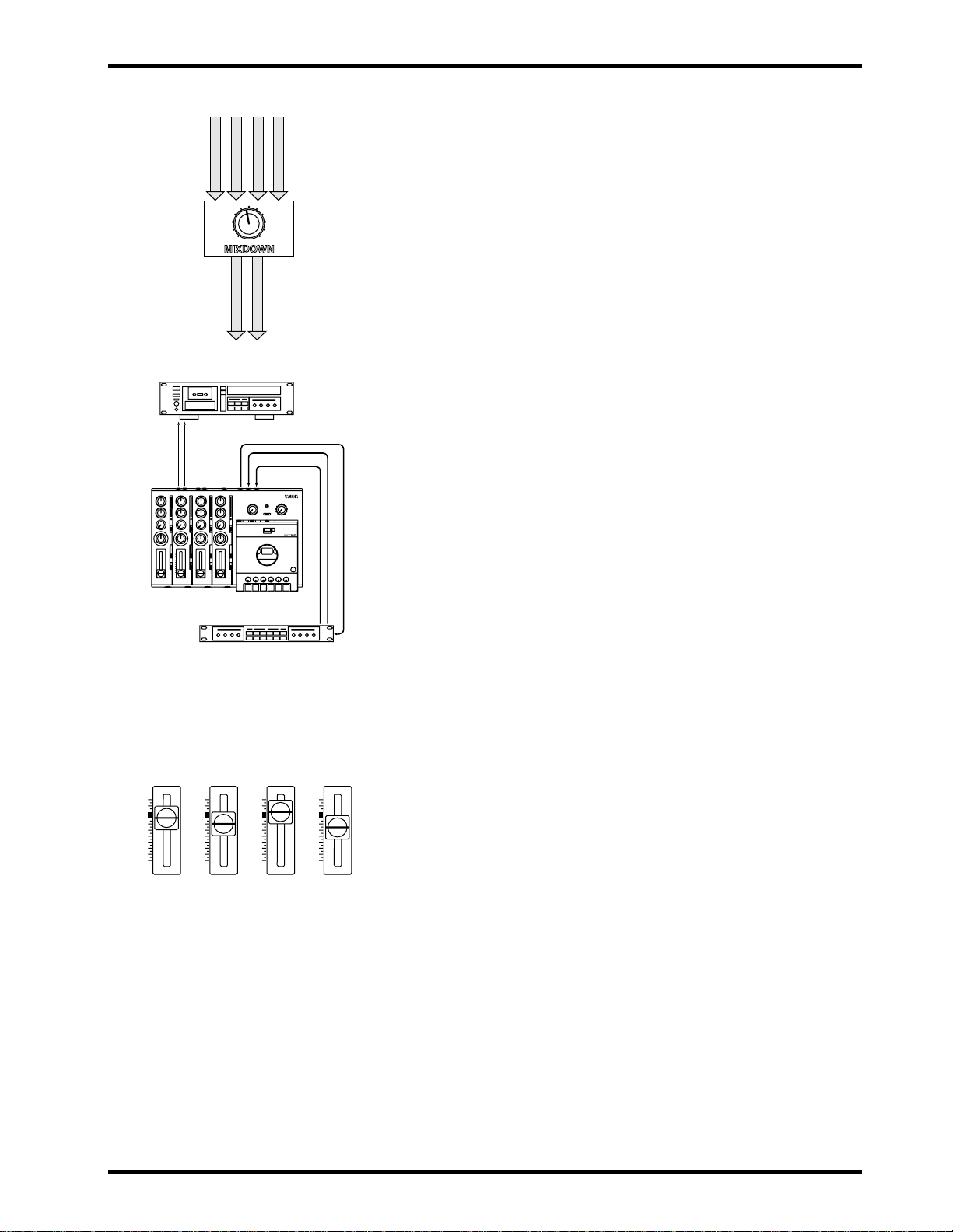
Step 5 — Mixing Down
Mixing-down is the process of combining all four tracks into one. This mix
can then be recorded to a stereo cassette recorder or DAT machine. The
MT50 is your multitrack recorder; the second tape recorder serves as the
“master recorder.” During the mix-down, you can tailor the tone of each
– +
sound using the two-band EQ, pan sounds left and right, and balance the
fader levels.
S
S
T
T
E
E
R
R
E
E
O
O
L
R
E
I
F
G
T
H
T
Preparation
1. Connect the STEREO OUT on the MT50 to the input on your master cassette recorder.
2. Set the input levels on your master recorder as appropriate.
3. You can connect the ster eo outputs of your master recorder to a hi-fi
amplifier , and connect a pair of speakers to the amplifier , to monitor
the mix.
Alternatively , you can use a pair of stereo headphones or a pair of speakers with built-in amplifiers. The best choice is a pair of speakers with a
flat response, uncolored by boosted bass or treble settings.
REC
4. You can connect a multi-effects processor, such as the Yamaha
REV100 or FX770, between the AUX SEND and AUX RETURN
jacks .
5. Set the MONITOR SELECT switch to STEREO.
6. Make sure that nothing is connected to the MIC/LINE inputs.
7. Set the dbx and ZERO STOP switches as appropriate. If you’re
continuing from the previous recording steps, they are set OK.
Balancing Levels
Before recording the stereo mix to tape, it’s best to rehearse it a few times
first, and then record it when you’re happy with the overall sound.
10
9
8
7
6
5
4
3
2
1
0
TRACK
1
10
9
8
7
6
5
4
3
2
1
0
TRACK
2
10
9
8
7
6
5
4
3
2
1
0
TRACK
3
10
9
8
7
6
5
4
3
2
1
0
TRACK
4
1. Set all faders to about 7.
2. Press PLAY to start playback.
3. Using the faders, adjust the levels to create a balanced mix. Nothing
too loud, nothing too quiet.
4. Use the MONITOR/PHONES level control to adjust the monitoring
volume to an optimal level.
MT50 User’s Guide
Page 18
14 Chapter 3: Basic Recording
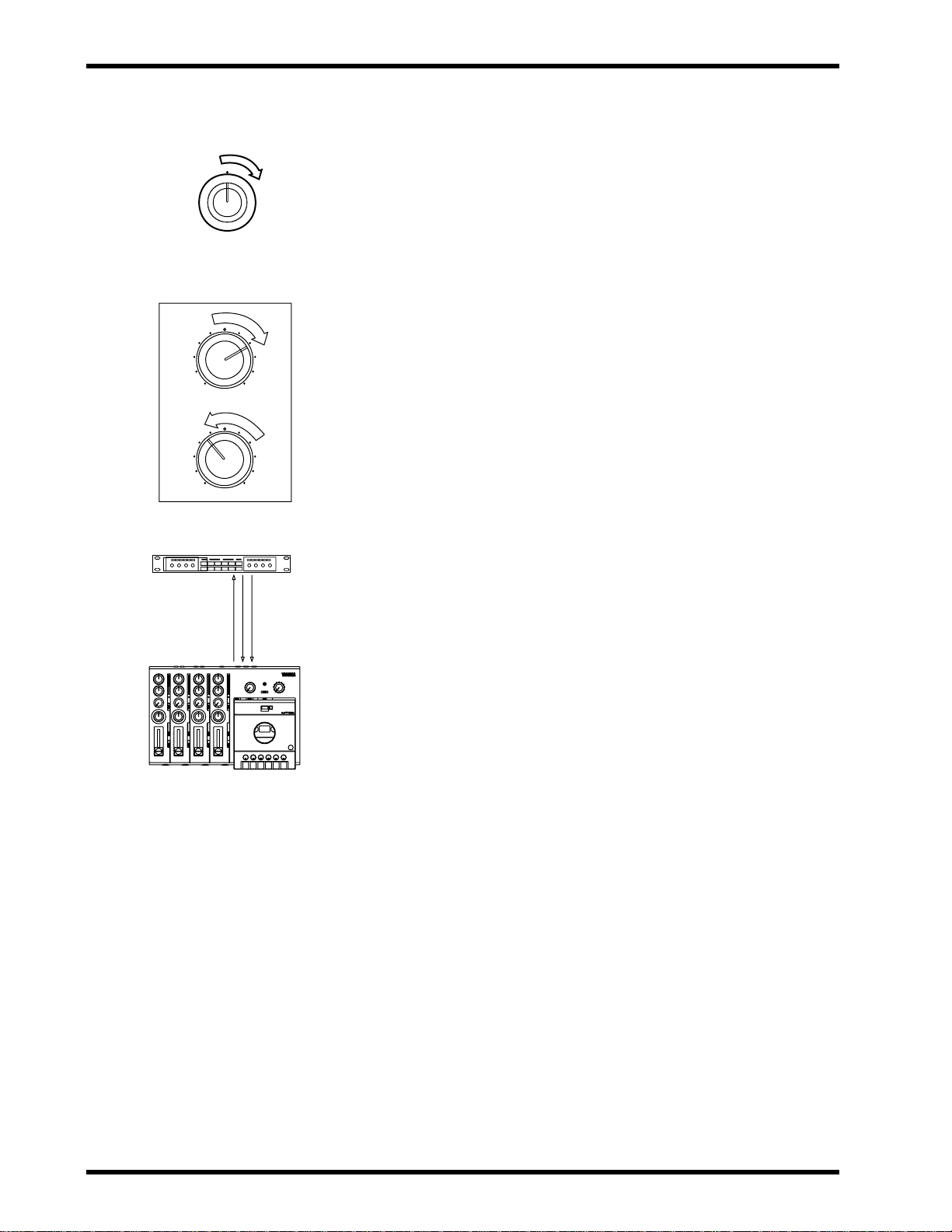
Panning
PAN
LR
HIGH
– +
LOW
– +
REC
Panning allows you to position sounds in the stereo mix (i.e., between the
left and right speakers). There are no hard and fast rules about positioning
instruments in the stereo image. Experiment! Some early Beatles recordings achieved remarkable effects by panning vocals, for example, hard
right, while bass and guitar were panned hard left.
1. Turn the PAN control to the left to position a sound to the left, and
to the right to position a sound to the right.
Applying EQ
The two-band equalizer enables you to boost or cut both high and low frequencies. Make sure you can hear desirable high frequencies, such as the
hi-hats in the drum track. Don’t let low frequencies, such as the bass track,
become too “boomy,” or overwhelm the mix.
1. Use the HIGH control to boost and cut high frequencies.
2. Use the LOW control to boost and cut low frequencies.
Adding Effects
If you have an effects processor, such as the Yamaha REV100 or FX770,
you can connect it to the MT50 and apply effects to recorded sounds.
1. Connect the AUX SEND to the effects processor’s input.
2. Connect the AUX RETURN to the effects processor’s outputs.
If you have a stereo effects processor, connect both the L(MONO) and
R AUX RETURN connectors. If your effects processor has a mono output, connect to the L(MONO) connector.
3. Turn up an AUX control to send a sound to the effects processor.
4. Turn up the AUX RETURN control to add the processed sounds to
the stereo mix.
! To prevent accidentally erasing
your original recor ding, remove the
write-protect tabs from both sides
of the audio cassette you used in
your MT50.
MT50 User’s Guide
Mixdown Recording
Once you’re happy with the mix, you’re ready to record it to the master
recorder.
1. Set your master recorder ready to record.
2. Play the MT50 and set the recording level on the master recorder.
3. Stop MT50 and rewind the tape back to approximately 999.
4. Start recording on the master recorder.
5. Press PLAY on the MT50 to start playback.
The stereo mix is recorded to the master recorder.
6. At the end of the song, stop the MT50 and master recorder.
7. Rewind the master recorder and play your masterpiece.
Page 19
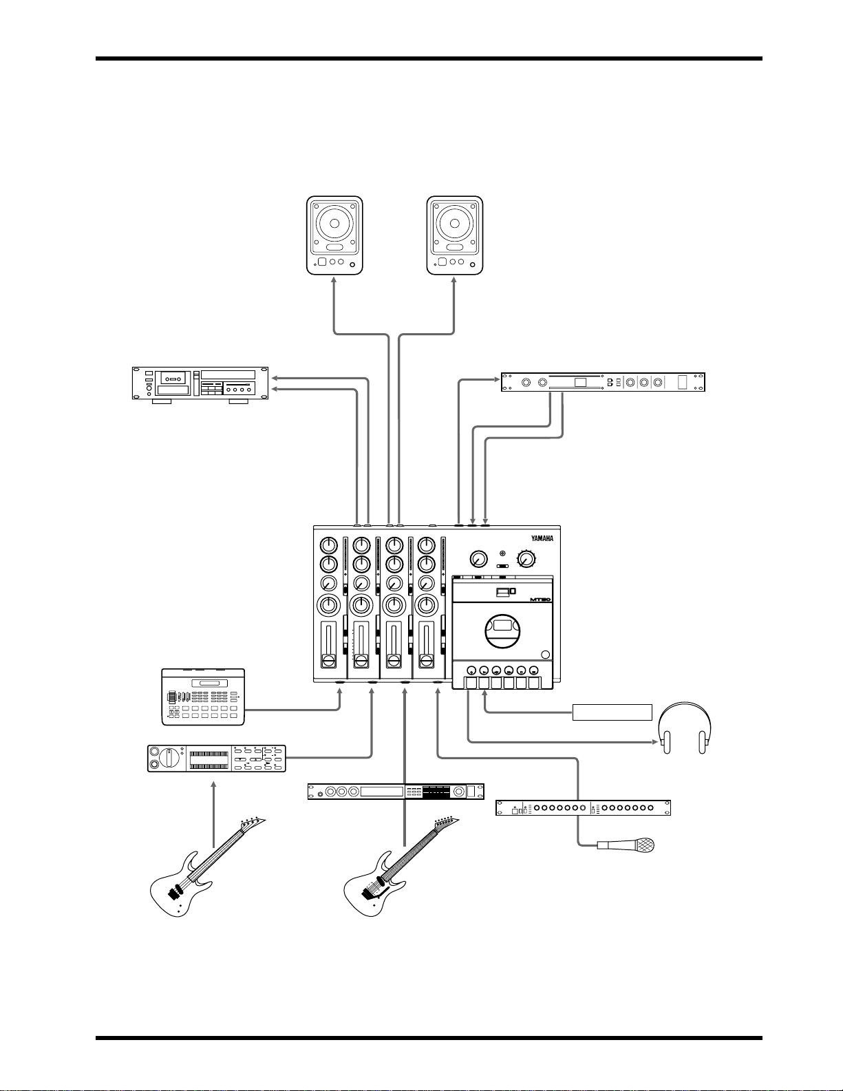
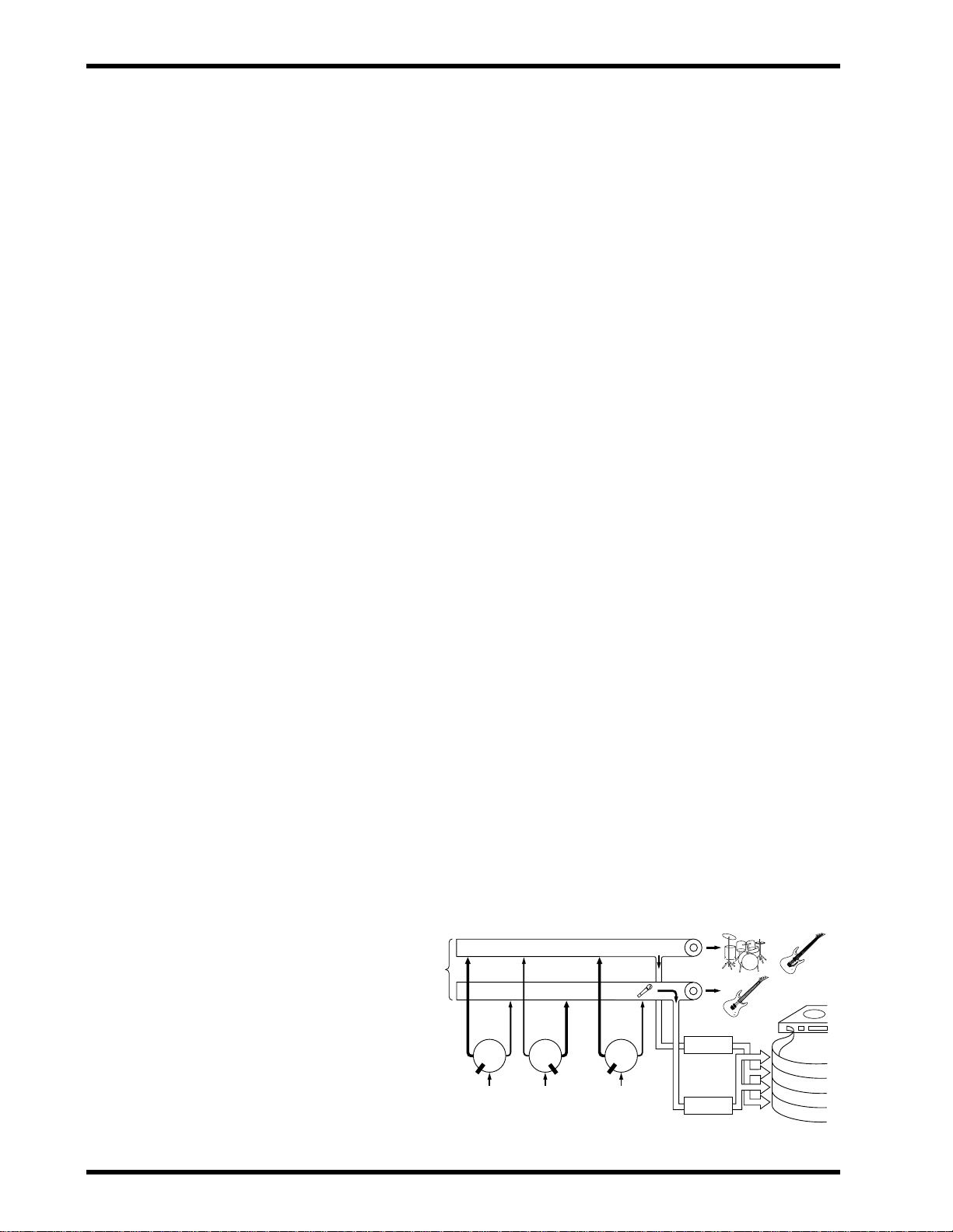
Setting example
Setting example 15
Powered Monitor Speakers
YAMAHA YAMAHA
Master Recorder
Drum Machine
Bass Effect Processor
YAMAHA
STEREO
OUT
REC
MONITOR
OUT
AUX
SEND
Effect Processor
YAMAHA
AUX
RETURNS
Footswitch
Guitar Effect Processor
Compressor
YAMAHA
MT50 User’s Guide
Page 20

16 Chapter 4: Advanced Recording
4
Advanced Recording
This chapter explains how to perform advanced multi-track recording techniques on your MT50. The MT50 is so flexible that you can perform sophisticated recording techniques with relative ease on a single, compact
machine. Here’s a little of what you can do.
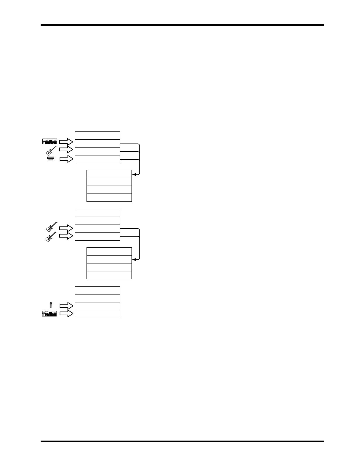
One-Take Recording
This recording technique is used to record several instruments at the same
time. It is extremely helpful for recording live performances. You can
record the instruments direct and apply reverb and other effects during mixdown at a recording studio.
Y ou can also use this technique to record four instruments liv e to two tracks,
leaving a couple tracks free. Or, you could record a complex drum part,
miking three drums in the kit separately. Later you could mix the tracks into
a very sophisticated rhythm part, and ping-pong it to the open track. Finally ,
you can also use this technique to retain the stereo placement of MIDI-programmable stereo devices.
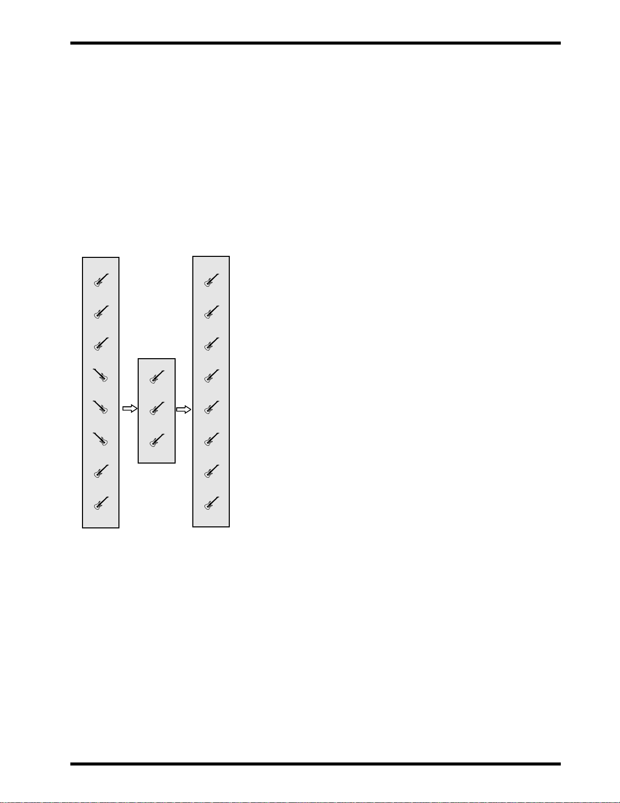
Ping-Pong Recording
Ping-Pong Recording takes its name from the parlor game that features a
little white bouncing ball. It allows you to combine previously recorded
tracks by mixing them together and recording (or “bouncing”) them to an
unrecorded track. Whereas basic overdub recording allows you to record
four times, this technique enables you to record, in theory, an unlimited
number of tracks. This is because each time you ping-pong, you make
tracks available for additional recording. Due to the limitations of magnetic
tape, however , you can record only se veral times before the tracks will deteriorate due to generational loss. (In other words, recording again and again
will wear down the tape so much that your tracks will lose their punch).
Punch-In/Out Recording
This technique is used to re-record short sections, correct mistakes, or add
new sections to silent passages. You play your part while punching in and
out to start and stop the recorder. If you have a footswitch, you can punch
in and out using your foot. This keeps your hands free for making music.
Its a great way to create a fantastic guitar solo. You can keep re-recording
difficult passages until you get things just right!
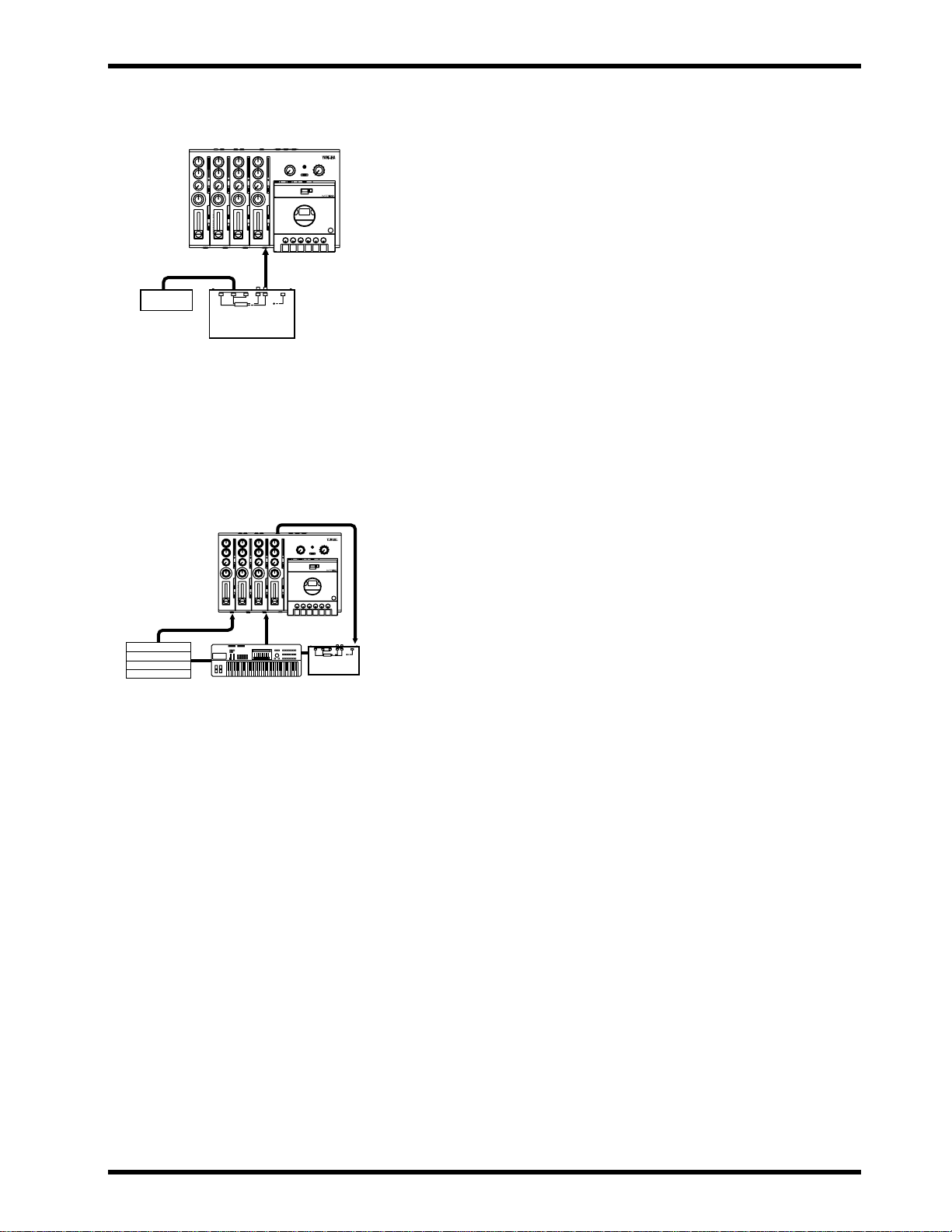
Synchronization
MT50 User’s Guide
By recording an FSK signal onto track 4, you can synchronize the MT50
with a drum machine or MIDI sequencer. With this technique, you don’t
need to record MIDI instruments to tape. You save tracks because the an
FSK signal triggers the MIDI instruments, effectively expanding your
song’s arrangement. This technique requires a MIDI to FSK converter , such
as the Y amaha YMC10.
Page 21
Drum Machine
One-Take Recording 17
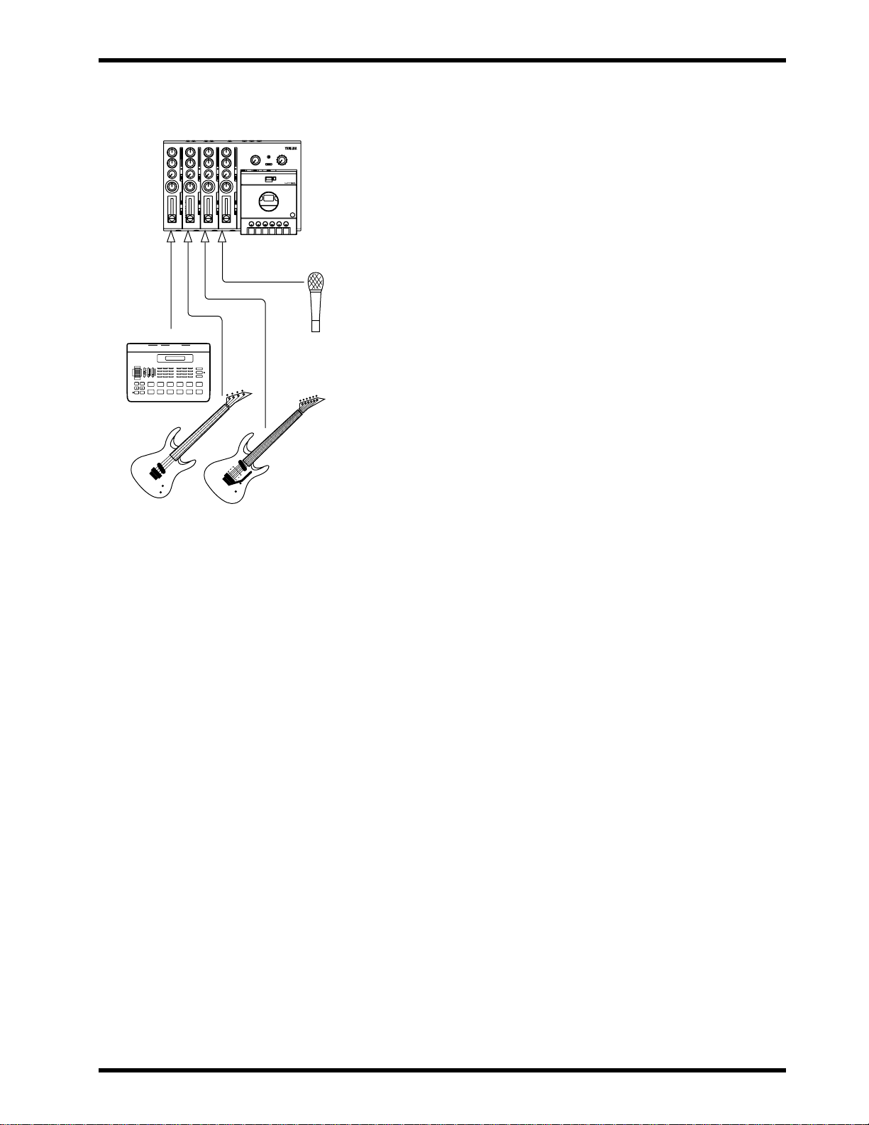
One-Take Recording
The MT50 enables you to record up to four instruments at the same time.
REC
This is useful for recording a live band, as discussed previously. Simply
record the instruments directly into input modules 1 through 4 and add
effects during mixdown.
1. Connect an instrument to MIC/LINE inputs 1 through 4.
2. Set the GAIN switches for Modules 1 through 4 as appropriate.
3. Set each module’s CUE slider to about 8.
4. Set each module’s REC SEL switch to its number (1, 2, 3, or 4).
The REC indicator starts flashing for each module.
5. Press the PAUSE button.
6. Press the REC button.
The REC indicator lights up.
7. Start up the band.
8. Raise each module’s fader gradually.
You should be able to hear the band; each module’s level meter should
light up.
9. Set the fader on each module so that the 0 light is on most of the time
and the +6 light comes on occasionally.
The module fader is used to set the recording level and should be set in
conjunction with the level meter. Use the CUE slider and MONITOR/PHONES control to adjust the monitoring levels. These controls
affect only the monitor signals.
10.Press the PAUSE button when you are ready to start recording.
11.Start up the band.
12.When the tune is finished, press STOP to stop recording.
13.Press REW to rewind the tape.
14.Mix down as described on page 13.
You can add effects to each channel separately, adjust the pan controls,
and balance the faders to achieve your desired results. You can also add
reverb to the entire mix for a polished, professional-sounding recording.
MT50 User’s Guide
Page 22
18 Chapter 4: Advanced Recording
Advanced One-Take Recording Techniques
What happens if you want to record musical instruments or electronic
devices that output stereo sound? With only four tracks, your options get
used up in a hurry!
There is another problem. An y spatial nuances--the subtle things you might
want to do with positioning sounds in the left-to-right stereo image--can be
lost if you have only one track reserved for your drum machine.
The special one-take recording capabilities of the MT50 explained below
allow you to accomplish some pretty slick tricks to solve these problems.
These techniques involve the MT50’s sophisticated ability to control the
placement of sound in the stereo image, and its ability to bounce multiple
left and right tracks to a stereo two-track mix.
This might sound complicated, but it’ s easy to do. It basically in v olv es just
two controls: the Record Select (REC SEL) switch and the PAN control.
For example:
• You can record four instruments at the same time, but use up only two
tracks in the process.
• Many drum machines, sequencers, and synthesizers output stereo
sound. Perhaps you spent a lot of time programming a drum machine so
that different drum sounds (bass, snare, etc.) are panned left or right in
the stereo image. This can make a recorded drum part far more dynamic.
Using this technique, you can preserve the stereo placement of a previously-programmed drum machine or synthesizer without running out of
tracks.
• Perhaps you want to create stereo guitar effects using, for example, a
stereo chorus connected to two guitar amplifiers with different tonal
characteristics or delay times. You might then record this stereo output
to two tracks so the left and right channels of your guitar solo have a different tone. If you bounce the solo to a single track, you would lose the
left-and-right placement of your guitar’s two tones, essentially undoing
your efforts. Using this technique, you can preserve the stereo nuances
of your solo.
The following diagram illustrates how signals from each PAN control are
routed to the stereo bus (the two thick horizontal pipes in the diagram) and
output via the STEREO OUT jacks. That is, each PAN control functions as
a “turn indicator” directing signals onto the stereo bus. The following pages
will explain how to record four musical instruments on two tracks, and ho w
to keep a stereo image of two instruments on a recording. As the diagram
shows, the L output is sent to tracks 1 and 3, and the R output is sent to
tracks 2 and 4.2
MT50 User’s Guide
STEREO BUSS
PAN PAN PAN
LRL
Drum
Module 1
Bass
Module 2
R . . . . . L
. . . . . . . . .
Guitar
4
R
STEREO OUT
L
R
To track 1 or 3
To track 2 or 4
&
4
3
2
1
Page 23

Module 1: Drums
Module 2: Bass
Module 3: Guitar 1
Module 4: Guitar 2
Track 4:
Track 3:
Track 2: Bass/Guitar 2
Track 1: Drums/Guitar 1
! In this example, we pan hard
right and hard left. This is just to
keep things simple. Experiment
with stereo placement. T ry panning
partially right or partially left to
create an interesting stereo image.
One-Take Recording 19
Recording Four Instruments to T wo T racks in One
Take
Say you want to record drums, bass, rhythm guitar, and lead guitar at the
same time while leaving a couple tracks open for later use.
1. Connect the drum mike to the MIC/LINE input of Module 1; bass
to Module 2; rhythm guitar to Module 3; and lead guitar to Module
4.
2. Adjust the GAIN switches, monitor controls. and input faders as
discussed in “Chapter 3: Basic Recording.”
3. Set the REC SEL switch for each module, as follows:
Set the REC SEL switch for Module 1 to “L.”
Set the REC SEL switch for Module 2 to “R.”
Set the REC SEL switch for Module 3 to “OFF.”
Set the REC SEL switch for Module 4 to “OFF.”
In this set-up, Tracks 3 and 4 will not be recorded. Track 1 will record
the left stereo channel. Track 2 will record the right stereo channel.
4. Set the PAN controls for each instrument’s stereo placement:
Set the PAN control for Module 1 to “L.”
Set the PAN control for Module 2 to “R.”
Set the PAN control for Module 3 to “L.”
Set the PAN control for Module 4 to “R.”
5. Press the REC button and start up the band!
The instruments you connected to inputs 1 and 3 will be combined on
Track 1. The instruments you connected to Inputs 2 and 4 will be combined on Track 2. Tracks 3 and 4 are available for additional recording.
MT50 User’s Guide
Page 24

20 Chapter 4: Advanced Recording
Module 1: Drums L
Module 2: Drums R
Module 3: Synth L
Module 4: Synth R
Track 4:
Track 3:
Track 2: Drums R/Synth R
Track 1: Drums L/Synth L
! You can record up to three dif-
ferent ster eo musical instruments by
connecting the third stereo instrument to the AUX RETURN jacks.
Preserving the Stereo Image of Two Instruments
1. Connect one stereo instrument to the MIC/LINE inputs for Modules 1 and 2 (L output to Module 1, R output to Module 2).
2. Connect another stereo instrument to the MIC/LINE inputs for
Modules 3 and 4 (L output to Module 3, R output to Module 4).
3. Adjust the GAIN switch, monitor controls, and input faders as discussed in “Chapter 3: Basic Recording.”
4. Set the REC SEL switch for each module, as follows:
Set the REC SEL switch for Module 1 to “L.”
Set the REC SEL switch for Module 2 to “R.”
Set the REC SEL switch for Module 3 to “OFF.”
Set the REC SEL switch for Module 4 to “OFF.”
5. Set the PAN controls to retain each instrument’s stereo placement
in the mix, as follows:
Set the PAN control for Module 1 to “L.”
Set the PAN control for Module 2 to “R.”
Set the PAN control for Module 3 to “L.”
Set the PAN control for Module 4 to “R.”
6. Press the REC button and start playing both stereo instruments.
The left channel of each stereo instrument will be mixed to T rack 1. The
right channel for each instrument will be mixed to T rack 2. Tracks 3 and
4 will be available for additional recording.
MT50 User’s Guide
Page 25
Ping-Pong Recording
Ping-Pong Recording 21
! The procedur e to the right stops
after we ping-pong Tracks 1, 2 and
3 onto Track4. However, there is no
need to stop there, as the following
illustration suggests. By repeatedly
bouncing tracks, you can make
your MT50 sound like a ten (or
more) track recording studio!
Track 3: Synthesizer
Drum Machine
Track 2: Bass
Track 1: Drums
Track 4: Rhythm Mix
(Track 3: Synthesizer)
(Track 2: Bass)
(Track 1: Drums)
Track 4: Rhythm Mix
(Track 3: Synthesizer)
Track 2: Guitar2
Track 1: Guitar1
Track 4: Rhythm Mix
Track 3: Guitar Mix
(Track 2: Guitar2)
(Track 1: Guitar1)
Track 4: Rhythm Mix
Track 3: Guitar Mix
Track 2: Synth Lead
Track 1: Vocals
! You cannot apply effects to or
adjust the balance of the tracks
mixed in ping-pong recording.
We recommend you to make any
necessary adjustments before
ping-pong recording.
Ping-Pong Recording allows you to bounce previously-recorded tracks to
an unrecorded track. Using this technique, you can create a recording with
more than four tracks.
This section explains two applications: example 1, mixing T racks 1, 2, and
3 to Track 4; and example 2, overdubbing a new sound source during
ping-pong recording.
This will free up Tracks 1, 2, and 3 for additional instruments, solos, or
vocals.
Example 1:
1. Begin by recording a different instrument on each of Tracks 1, 2,
and 3.
For example, you could record drums, bass, and synthesizer (or substitute other instruments). See Chapter 3: Basic Recording for more information. Don’t forget to set the ZERO STOP switch.
2. Rewind the tape to the start of the song.
3. Disconnect any instruments that may be connected to the
MIC/LINE inputs for Tracks 1, 2 and 3.
4. Set the MONITOR SELECT switch to CUE.
5. Set the MONITOR/PHONES control to about half-way.
Adjust it later if the monitors are too loud or too soft.
6. Turn the PAN controls for Modules 1, 2, and 3 all the way to the
right (R).
The signal from Modules 1, 2, and 3 is routed to stereo bus output R.
7. Set the REC SEL switch for Modules 1, 2, and 3 to OFF.
We don’t want to record anything over our previously-recorded tracks.
8. Set the REC SEL switch for Module 4 to R.
The REC indicator for Module 4 is flashing.
In this way, you can record Tracks 1, 2, and 3 onto Track 4.
9. Set the faders for Modules 1, 2, and 3 to about 7.
10.Set the CUE level of Module 4 to about 7.
11.Press the REC button to start a temporary recording.
12.Adjust the recording level of Track 4, while balancing the volume
level of Tracks 1-3.
Use the module 1, 2, and 3 faders to adjust the level balance so that the
level meter +6 of Module 4 will light up momentarily.
13.Once you have determined the correct position for the input fader
for Module 1–3, repeat the process for the final ping-pong.
MT50 User’s Guide
Page 26

22 Chapter 4: Advanced Recording
! Lower the faders of the tracks
you do not want to include in the
mix when ping-pong recording.
You can use this process over again to combine and mix three tracks into
one. Unfortunately, the sound quality will deteriorate rapidly after a couple
of bounces. Using this technique, the MT50 can function as though it had
far more than four tracks!
You can perform ping-pong recording of Tracks 1, 2, and 3, and simultaneously overdub an instrument connected to Module 4.
The procedure is almost the same as that described above (1-13), except for
the following steps:
Example 2:
3’. Connect an instrument to Module 4.
6’. Turn the PAN control for Module 4 all the way to the right (R).
12’. Adjust the recording level of Track 4 so that the +6 level meter f or
Module 4 lights up momentarily, while balancing the volume le vel
of Tracks 1-4 using the faders.
Note: Avoid ping-pong recording to an adjacent track (for example,
bouncing track 2 to track 1 or track 3) as much as possible. Otherwise,
cross-talk (signal leak at the recording head) may cause feedback
When you are ping-pong recording to an adjacent track, set the recording
level carefully. Do not boost the HIGH EQ too much.
We also recommend that you set the dbx ON to avoid feedback as much as
possible.
MT50 User’s Guide
Page 27
Track 4:
Guitar Solo
Track 4:
Solo Punch-In
Track 4:
Solo Punch-Out
Track 4:
Repaired Guitar Solo
! Make sure you r e-play enough of
the solo to make it flow smoothly.
! Practice playing along with your
guitar solo a few times through the
end of Bar 4 to get ready for the
actual punch-in. Work on your timing, and try to make the new performance of Bar 4 blend in smoothly
with the existing take.When you are
satisfied, rewind the tape.
Yamaha supplies an optional footswitch, FC-5. Note that using a footswitch other than Yamaha’s may
cause mistiming.
Punch In/Out Recording 23
Punch In/Out Recording
This technique is used to re-record mostly to correct mistakes by re-recording a short section of tape on one track.
For example, say you just played a great guitar solo over some basic rhythm
tracks, but you flubbed a couple of notes in Bar 4. The solo was recorded to
Track 4. (Other instruments occupy Tracks 1, 2, and 3.)
You could punch-in at the start of Bar 4, play your part again (this time hitting every note perfectly!) and punch out at the end of Bar 4. When you listen to the playback of the solo, the punch-in edits are flawless! Nobody will
ever know that you didn’t play the part perfectly the first time.
You can punch in and out with or without a footswitch. This section
explains both methods, but we recommend that you use the footswitch
since you can operate it with your foot.
Punch in/out recording using a footswitch:
1. Connect a footswitch to the PUNCH I/O jack.
2. Set the REC SEL switches for Modules 1, 2, and 3 to OFF.
3. Set the REC SEL switch for Modules 4 to “4.”
The REC INDICATOR for Track 4 will start flashing.
4. Set the MONITOR SELECT switch to MIX.
5. Make sure the MONITOR/PHONES control is set as it was before.
6. Make sure the input fader for Modules 4 is set to the same level as
it was during the original take of your guitar solo.
If you record the punch-in at a different volume level, it will not blend
into the previously-recorded track and your edit will be obvious.
7. Press the PLAY button to play the song for the actual punch-in.
8. Play along with your guitar solo, or get ready to start in tempo at
the start of Bar 4.
Tapping your foot can help a lot!
9. At the start of Bar 4, press the footswitch to start recording over
T rack 4. Play Bar 4 of y our solo. At this time, the REC indicator of
Module 4 lights up.
The timing is critical. If you start too early, you will erase recorded
material before Bar 4--the stuff you want to keep!
10.At the end of Bar 4, step on the footswitch. The REC indicator of
Module 4 flashes.
Again, the timing is critical. If you step on the footswitch to stop recording too late, you will erase material after Bar 4.
Punch in/out recording without using a footswich:
The basic procedure is the same as that with a footswitch, except for the following steps:
1’. (No connection.)
9’. Set the REC SEL switch while holding down the PLAY button to
4 at the beginning of Bar 4, start recording on T rack 4 and play the
instrument.
10’. At the end of Bar 4, set the STOP to OFF.
MT50 User’s Guide
Page 28
24 Chapter 4: Advanced Recording
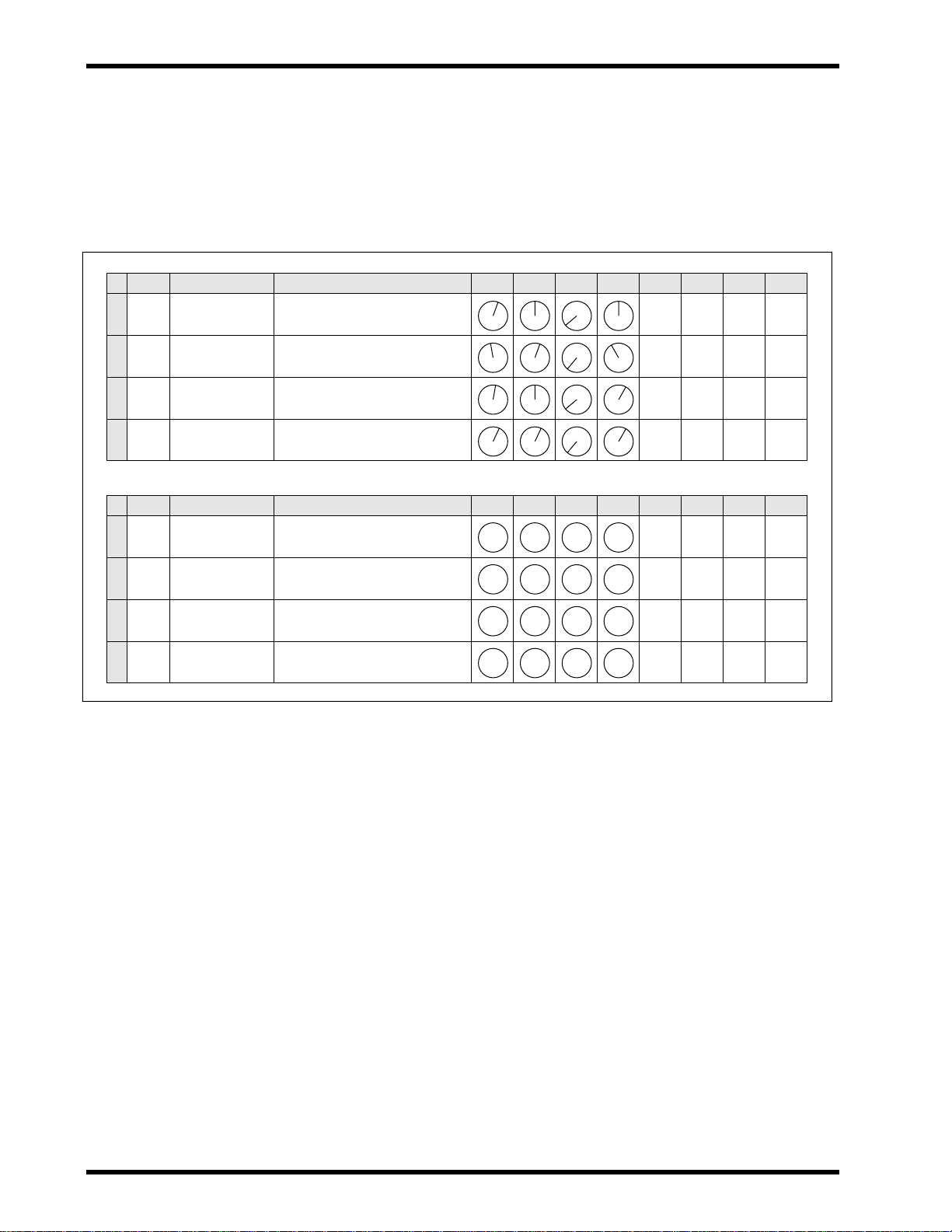
Using a Tracking Sheet
The following illustration shows how to fill out a Tracking Sheet. You can
write down the instrument played on each track and mark the settings of the
panpots and faders for future reference. A blank Tracking Sheet appears in
the Appendix. Photocopy it for repeated use. The information can prove
valuable later when you want to recreate a particular sound.
A Track Instrument Other Info
1
Drum Machine
2
Bass
3
Rythm Guitar
4
Lead Guiiar
B Track Instrument Other Info
1
2
Guita mix
3
4
Drum/Bass
Program 012
Alembic through Ampeg
Gibson ES-225, Mesa Boogie
‘57 Strat, tweed Princeton
ES-225 and Strat
Rhythm track
High Low Aux Pan Fader Start Stop
7
000
350
7
000
350
7
064
350
8
172
280
High Low Aux Pan Fader Start Stop
350
064
350
000
To Track
B-4
B-4
B-2
B-2
To Track
MT50 User’s Guide
Page 29
REC
IN
OUT
MIDI
YMC10
Converter
! You can take the sound output
from the MIDI instrument and
recor d it on any open track, syncing
the MIDI performance with your
own!
REC
Tone Generator
Drum Machine
Sampler
Effects
Converter
! T o make sure a sync r ecording is
done correctly:
Note the following items to make
sure sync recording is done correctly.
• Set the FSK signal recording
level of track 4 between 0 and
+3dB.
• When the dbx switch is set to
"SYNC", do not recor d any musical on track 4.
• Try not to record music on an
adjacent track (track 3) during
sync recording (when playing
back the FSK signal on track 4).
Synchronization 25
Synchronization
By recording a timecode onto Track 4, you can synchronize the MT50 with
a MIDI sequencer or drum machine.
(FSK stands for Frequency Shift Keying, in case you were wondering. It is a type of MIDI
performance tempo data. The track that contains the FSK signal is a little like the conductor
of an orchestra who controls the tempo for your sequencers or drum machines.).
If this applies to your sequencer or drum machine, purchase Yamaha YMC
10 MIDI FSK converter and connect it between your MIDI sequencer or
drum machine and the MT50.
1. Connect the Tape Sync Out from YMC 10 to the MIC/LINE input
of Module 4.
2. Set the sync clock on your MIDI device to “Internal.”
3. Set the input fader of Module 4 to about 8
4. Set the dbx switch to the SYNC or OFF position.
When the dbx switch is set to SYNC, Tracks 1, 2, and 3 are set to dbx
ON. Track 4 is set to OFF.
5. Set the REC SEL switch for Modules 1, 2, and 3 to “OFF.” Set the
REC SEL switch for Module 4 to “4.”
The REC indicator for Module 4 is flashing.
6. Press the REC button.
The REC indicator lights up.
7. Play your sequencer or drum machine and record FSK signal for
the duration of your song.
8. When finished, remove the cable from Module 4.
9. Rewind the tape.
10.Connect the MT50’s Sync Out jack to the YMC10 Tape Sync In
jack.
11.Set up your MIDI sequencer or drum machine for sync playback.
(Set the sync clock on MIDI device to “MIDI”). See the manual that
came with the sequencer or drum machine for more information.
12.Press the PLAY button on the MT50.
Your MIDI sequencer or drum machine will be triggered by the sync
signal output from the MT50.
13.Play along with the MIDI parts using your guitar, voice, piano, etc.,
and record them using the basic techniques discussed earlier.
MT50 User’s Guide
Page 30

26 Appendix
Appendix
Troubleshooting
If you’re ha ving trouble operating MT50, or it doesn’ t seem to be w orking
as it should, look up the symptoms in the following table and see what to do.
Symptom What to Do
Make sure the AC adaptor is connected to a
suitable AC outlet.
Make sure the AC adaptor is connected to
MT50 cannot be powered ON.
Cannot record.
Recordings sound noisy or distorted.
Recordings sound dull, suffer from wow
and flutter, or are of poor quality.
Cannot play.
Recordings playback at the wrong pitch.
Cannot send signal to external effects
processor, or the effects processor does
not correctly apply an effect.
No sound from headphones.
When overdubbing, you can’t hear the instrument you’re playing.
Tape sync does not function correctly.
MT50’s DC 12V connector.
Make sure the POWER switch on MT50’s
rear panel is set to ON.
If MT50 still cannot be powered ON, please
contact your Yamaha dealer.
Make sure there’s a cassette loaded.
Make sure the tape’s not wound all the way
to the end.
Make sure that the cassette’s record protect
tabs are intact.
Check to see if the REC SELECT switch is
set correctly.
When recording, make sure you set the fader
so that the 0 light is on most of the time and
the +6 light is on occasionally. If the signal
level is too low, the recording may sound
noisy. If it is too high, distortion may occur.
Be sure to use high-quality Type II (High
Bias 70 µs EQ) chrome cassettes.
Clean the tape head and mechanism. See
“MT50 Maintenance” on page 27.
Try a new cassette.
Make sure the cassette is loaded correctly.
Make sure the tape’s not wound all the way
to the end.
Make sure you have not changed the posi-
tion of the PITCH slider since recording.
Turn up the channel’s AUX control and
raise the fader. Check the AUX RETURN
level.
Turn up the MONITOR/PHONES control.
Make sure the MONITOR SELECT switch
is set correctly.
Raise the fader for the input module. Make
sure the MONITOR SELECT switch is set
to CUE. Raise the CUE slider.
Make sure the recording level of the FSK
signal is set to about +3dB. Make sure that
you are not using an overly-worn tape.
Check your sequencer’s manual for information. If you are using a MIDI-to-FSK
converter, make sure it is connected correctly.
MT50 User’s Guide
Page 31

MT50 Maintenance 27
MT50 Maintenance
The MT50 requires regular maintenance to remain in top operating condition. If you perform the following simple maintenance procedures at regular intervals, your MT50 will be a faithful musical companion for many
years.
• Clean the recording head, capstans, and rollers. (See the “Precautions”
at the start of this user’s guide.)
• Demagnetize the recording head at regular intervals.
Cleaning the Recording Head and Components
The recording heads are the delicate components that touch the recording
tape. Over time they tend to become coated with an oxide residue and need
to be cleaned. (Otherwise, you’ll soon notice a lack of high frequencies in
your recordings.)
The surrounding components--called capstans and rollers--also tend to
become coated with residue and dust particles. (This increases the wow and
flutter of your recordings.)
T o clean the recording head and capstan, use a head-cleaning kit. These kits
generally include specially-made cotton swabs and an isopropyl alcoholbased cleaning solution, and are.available at audio and electronics shops.
Follow the directions on the kit, carefully wiping the recording head and the
capstan with a swab soaked in cleaning solution.
It is best to clean the rollers with a non-alcohol based rubber cleaning solution, which is often included in the cleaning kits. Alcohol tends to dry out
and corrode the rubber part of the roller.
Clean these components often, after no more than ten hours of recording
use. If the head becomes dirty, the MT50 may sound distorted or noisy. In
severe cases, the MT50 may not be able to playback or record at all. If you
expect optimal results from a recording session, it is best to clean the heads
before the session.
Capstan
Clean the Shaded Areas
Pinchroller
Record/playback head
Erase head
MT50 User’s Guide
Page 32

28 Appendix
Demagnetizing the Recording Head
As the recording tape passes over the recording head, it tends to impart a
tiny amount of magnetism to the head. The head collects this magnetism
over a period of time, slowly becoming magnetized. You need to demagnetize the head using a commercially-available head demagnetizer . (These are
also available at most audio and electronics shops.) Read the directions on
the demagnetizer carefully. If you do not use the demagnetizer correctly,
you could seriously damage the recording head. Also, keep recorded tapes
away from the demagnetizer when it is in use; the demagnetizer can accidentally erase your tapes!
It is best to demagnetize the recording head after no more than ten hours of
recording use. If you are planning a special session, it is a good idea to clean
and demagnetize the head before the session to ensure the best sounding
results.
MT50 User’s Guide
Page 33

Specifications
General Specifications
Tape Type C46–90 cassette (Type II High Bias 70 µs EQ)
Track Format 4 tracks
Head System
Tape Transport
Mixer Specs
Recorder Specs
Connections
General
Motor DC servo
Tape Speed 9.5 cm/sec
Pitch Control ±10%
Wow & Flutter 0.12% W. RMS
Rewind Time C60 tape → Approx.120 seconds
Frequency Response
S/N Ratio
EQ
Frequency Response 40 Hz–16 kHz +3, –5 dB (dbx* OFF)
S/N Ratio (@3% THD) 85 dB (dbx* ON, IHF-A)
Distortion 1.5% (400 Hz, –10 dB recording level)
Erasure Ratio 55 dB (1 kHz, 0 dB recording level, dbx* OFF)
Noise Reduction dbx*
MIC/LINE
AUX RETURN L/R
STEREO OUT L/R
AUX SEND
MONITOR OUT L/R
SYNC OUT
PHONES (stereo)
Power Supply AC adaptor (PA-1206)
Dimensions (W × H × D) 337 × 69.3 × 231 mm
Weight 1.7 kg
Option FC5 Footswitch for punch-in/out recording
Specifications 29
4-channel record/playback (hard permalloy head)
4-channel erase (ferrite head)
MIC IN to STEREO OUT, LINE IN to STEREO OUT, LINE IN to PHONES
OUT: 20 Hz–20 kHz +1, –4 dB
MIC IN to STEREO OUT: 68 dB, IHF-A (GAIN: MIC)
LINE IN to STEREO OUT: 70 dB, IHF-A (GAIN: LINE)
LOW: ±12 dB, 80 Hz, shelving
HIGH: ±12 dB, 12 kHz, shelving
Input impedance: 10k Ω
Nominal input level: –10, –30, –50 dB (fader nominal)
Min. input level: –56 dB (gain control MIC, fader max)
Max. input level: +6 dB (gain control LINE, fader nominal)
Input impedance: 10k Ω
Nominal input level: –10 dB (AUX RETURN control nominal)
Min. input level: –16 dB (AUX RETURN control max)
Output impedance: 1k Ω
Nominal load impedance: 10k Ω
Nominal output level: –10 dB (10k Ω load)
Nominal load impedance: 8–40 Ω
Max. output level: 30mW (40 Ω load)
0 dB = 0.775 V rms
* dbx noise reduction system was manufactured based on a patent license from THAT Corporation.
dbx is a trademark of Carillon Electronics Corporation.
All specifications subject to change without notice.
MT50 User’s Guide
Page 34

30 Appendix
Block Diagram
MIC/LINE
MIC/LINE
MIC/LINE
MIC/LINE
AUX RETURN
L
(MONO)
R
SYNC
OFF
OFF
OFF
OFF
1
L
REC
SEL
2
R
REC
SEL
3
L
REC
SEL
4
R
REC
SEL
OFF
ON
MONITOR/
PHONES
METER
dbx
dbx
CUE
METER
dbx
CUE
METER
dbx
CUE
METER
dbx
CUE
SYNC OUT
L
STEREO
OUT
R
L
MONITOR
OUT
R
PHONES
STEREO
L
AUX
R
EQ BA
1
2
3
4
MIC
LINE
MIC
LINE
MIC
LINE
MIC
LINE
GAIN
GAIN
GAIN
GAIN
HA
LOW
HIGH
HA
LOW
HIGH
HA
LOW
HIGH
HA
LOW
HIGH
AUX RETURN
PAN
AUX
BAEQ
PAN
AUX
BAEQ
PAN
AUX
BAEQ
PAN
AUX
R
P
R
P
R
P
R
P
STEREO
MIX
CUE
REC
REC
REC
REC
MONITOR
SELECT
Dimensions
AUX SEND
H: 69.3
D: 231
W: 337
MT50 User’s Guide
Page 35

Specifications 31
Glossary
AUX RETURN (Auxiliary Return) — The AUX RETURN control
determines the amount of signal that is fed back to the MT50 via the AUX
RETURN input connectors (generally after processing by an external
effects unit connected to the AUX SEND).
AUX SEND (A uxiliary Send) — Each module includes an AUX SEND
control, which determines the amount of signal fed to the AUX SEND output connector (generally for processing by an external effects unit).
Capstan — The slender, pin-like component adjacent to the roller. The
tape passes between the capstan and roller.
CUE slider — Each module includes a CUE slider, which controls the
amount of signal fed to the CUE signal path. The MONITOR SELECT
switch includes a setting for CUE monitoring.
DAT (Digital Audio Tape) — Audio tape that records a digital, as
opposed to analog, signal on a magnetic recording tape. DAT machines are
often used as master recording units.
dbx noise reduction — Tape recording is always noisy. MT50 uses dbx
noise reduction to reduce noise and keep your recordings clean and crisp.
Demagnetizer — A hand-held device shaped like a small wand attached
to an electric cord. The demagnetizer removes the magnetic field that routinely builds up on a recording head and is an integral part of maintaining
any tape recorder.
Equalization (EQ) — The process of adjusting (boosting or cutting) the
high and low frequency ranges for optimal sound. Each module contains
both a HIGH and LOW equalization control, which function much like the
bass and treble controls on a stereo hi-fi system.
Fader — Each module contains a fader , which is a large slider that controls
the input level during recording and the output level during playback.
FSK (Frequency Shift Keying) — A device that translates MIDI clock
data into frequencies that can be recorded for synchronization purposes.
GAIN switch — Various musical instruments and devices output differ-
ent levels of signal. Gain is a measure of electronic input ov er output. Each
module includes a GAIN switch that can be set to line, instrument, or
microphone levels.
Head — The delicate metal component that touches the magnetic record-
ing tape, imparting the signal to be recorded.
Instrument level — The level of gain output by such devices as an elec-
tric bass or guitar. Set the GAIN switch to about halfway for an instrument-level.
Line level — The level of gain output by such devices as a synthesizer,
drum machine, CD player, etc. The lowest setting of the GAIN switch.
Master recorder — A second tape recorder used during the mixdown
process. The master recorder can be any two-track stereo recorder, such as
a standard cassette, reel-to-reel, or DAT recorder.
MIC/LINE input — Each module includes a MIC/LINE input to con-
nect a musical instrument or electronic device for recording.
MT50 User’s Guide
Page 36

32 Glossary
MIDI (Musical Instrument Digital Interface) — A digital data format
standardized to ensure compatibility between electronic musical instruments from different manufacturers.
Mixdown — The recording process by which you combine multiple
tracks (often four) into a stereo mix.
Module — The MT50 includes four modules, which are the groups or col-
umns of identical controls on the left side of the MT50.
MONITOR/PHONES control — Controls the amount of signal fed to
the speakers through the left and right MONITOR OUT jacks or to the
Headphone jack.
Multitrack — Audio recording in which a multitrack tape recorder cre-
ates multiple independent tracks (four on the MT50) on magnetic tape
allowing for control and processing of individual instruments or signals.
One-Take recording — Recording several instruments simultaneously
(four on the MT50) for later mixdown. Excellent for recording a live band.
Overdub recording — Recording one track while listening to another
track or tracks. Excellent for individuals recording multiple instruments in
sequence, such as a song demo
Pan — Controls that shift a signal to the left or right side of a stereo image.
From the word “panoramic.” Each module includes a PAN control.
Pitch —The relative frequency of a musical sound; its highness or low-
ness. The PITCH slider controls the pitch of a recorded playback by
fine-tuning the speed at which the tape rolls over the head.
Ping-Pong recording — Also known as bouncing. The transfer of a
recording from one track to another to effectively increase the number of
tracks available for recording.
Post fader — MT50’s aux sends are configured post fader, which means
that the aux send signal is sourced after the fader. To feed a signal to an
external effects processor via the aux send, turn up the AUX control and
raise the fader. The advantage is that you can fade both channel and aux
send signals simultaneously. Compare with Pre-fader.
Pre-fader — A signal that is sourced before the fader , therefore, the fader
has no control on the signal.
Punch-In/Out recording — A recording technique used primarily to
correct mistakes by re-recording over a short section of a track.
Roller — The small, rubber wheel near the capstan that smooths the move-
ment of the tape over the head.
Stereo mix — A two-track mix with left and right stereo channels. The fin-
ished product of a mixdown session.
Striping the tape — Applying a timecode to the tape for synchronization
purposes. On the MT50, you apply the timecode to Track 4.
Synchronization — The technique of coordinating external MIDI instru-
ments and the playback of the MT50 via a timecode.
Track — A ph ysical band on a recording tape created by a recording head.
The MT50 creates four tracks on one side of a standard audio cassette.
Tracking sheet — A chart that lists what is to be recorded on each track
and in what order.
MT50 User’s Guide
Page 37

Multitrack Cassette Recorder
Manuel de l’utilisateur
Français
Page 38

i
Précautions
Veuillez lire les précautions suivantes avant de manipuler votre MT50.
Sécurité
• Assurez-vous que le câble d’alimentation n’est pas placé dans un
endroit où l’on risque de marcher dessus ou de l’écraser sous d’autres
appareils.
• Evitez d’exposer le MT50 au soleil, à des températures extrêmes, à une
forte humidité, à la poussière ou à des chocs violents.
• La température ambiante de la pièce dans laquelle vous installez le
MT50 doit être située entre 10˚C et 35˚C (50˚F et 95˚F).
• N’utilisez que l’adaptateur fourni avec le MT50. Evitez les adaptateurs
d’une autre marque.
• L’adaptateur doit être branché à une prise du type précisé sur l’adaptateur lui-même ou dans ce Manuel de l’utilisateur.
• Avant de brancher l’adaptateur au MT50, débranchez-le de la prise
d’alimentation. Il faut toujours d’abord brancher l’adaptateur au MT50
puis à une prise d’alimentation.
• Prenez toujours l’adaptateur fermement en main pour le débrancher le
la prise d’alimentation. Ne tirez jamais sur le cordon.
Manipulation
• Pour évitez tout risque d’électrocution, n’ouvrez pas le MT50.
• Afin de réduire le risque d’incendie et d’électrocution, évitez toute
exposition du MT50 à une forte humidité ou à de la pluie.
• Dans un environnement fort humide, de la condensation peut se former
sur les parois intérieures et extérieures du MT50. S’il y a de la condensation, laissez le MT50 sous tension sans l’utiliser. Attendez que la condensation ait entièrement disparu.
Entretien
• Utilisez un chiffon doux et sec pour nettoyer le MT50.
• Si le MT50 nécessite un nettoyage plus approfondi, servez-vous d’un
chiffon doux, légèrement humide. Pour les traces plus tenaces, utilisez
un détergent doux. Evitez les détergents plus agressifs et ceux à base de
solvants tels que l’alcool et le benzène.
Dépannage et réparations
• Pour tout entretien ou réparation, veuillez vous adresser à un personnel
qualifié.
• Si vous avez un des problèmes sui v ants, veuillez v ous adresser à un personnel qualifié:
La prise ou le câble de l’adaptateur est endommagé.
Des objets métalliques ou du liquide ont pénétré dans le MT50.
Le MT50 est resté sous la pluie.
Le MT50 est tombé ou son boîtier est endommagé.
Le MT50 ne fonctionne pas normalement ou vous avez remarqué un
changement prononcé de ses performances.
© 1994 Yamaha Corporation.Tous droits réservés.
Toutes les marques sont la propriété de leurs détenteurs respectifs.
Manuel de l’utilisateur MT50
Page 39

ii
Table des matières succinte
1 Introduction au MT50 . . . . . . . . . . . . . . . 1
En ce qui concerne ce manuel . . . . . . . . . . . . . . . . . . . . . 1
Qu’est-ce que le MT50? . . . . . . . . . . . . . . . . . . . . . . . . . . 1
Choix des cassettes . . . . . . . . . . . . . . . . . . . . . . . . . . . . . . 2
Enregistrement multipiste . . . . . . . . . . . . . . . . . . . . . . . . 2
Avez-vous assez avec quatre pistes? . . . . . . . . . . . . . . . . 2
Quelques suggestions . . . . . . . . . . . . . . . . . . . . . . . . . . . . 3
2 Présentation du MT50 . . . . . . . . . . . . . . . 4
Bornes . . . . . . . . . . . . . . . . . . . . . . . . . . . . . . . . . . . . . . . 8
3 Enregistrement élémentaire . . . . . . . . . . . 9
Chargement de cassette dans le MT50 . . . . . . . . . . . . . . . 9
Mise sous tension . . . . . . . . . . . . . . . . . . . . . . . . . . . . . . . 9
Préparation . . . . . . . . . . . . . . . . . . . . . . . . . . . . . . . . . . . . 9
Etape 1 — Enregistrement de la batterie . . . . . . . . . . . . 10
Etape 2 — Enregistrement de la basse . . . . . . . . . . . . . . 11
Etape 3 — Enregistrement de la guitare . . . . . . . . . . . . . 12
Etape 4 — Enregistrement du chant . . . . . . . . . . . . . . . . 13
Etape 5 — Mixage . . . . . . . . . . . . . . . . . . . . . . . . . . . . . 14
Préparation . . . . . . . . . . . . . . . . . . . . . . . . . . . . . . . . . . . 14
Balance des niveaux . . . . . . . . . . . . . . . . . . . . . . . . . . . . 14
Panoramique . . . . . . . . . . . . . . . . . . . . . . . . . . . . . . . . . . 15
Egalisation . . . . . . . . . . . . . . . . . . . . . . . . . . . . . . . . . . . 15
Ajouter des effets . . . . . . . . . . . . . . . . . . . . . . . . . . . . . . 15
Enregistrement du mélange . . . . . . . . . . . . . . . . . . . . . . 15
Exemple d’utilisation . . . . . . . . . . . . . . . . . . . . . . . . . . . 16
Manuel de l’utilisateur MT50
4 Enregistrement avancé . . . . . . . . . . . . . . 17
Enregistrement en une prise . . . . . . . . . . . . . . . . . . . . . . 17
Enregistrement ping-pong . . . . . . . . . . . . . . . . . . . . . . . 17
Enregistrement par insertion . . . . . . . . . . . . . . . . . . . . . 17
Synchronisation . . . . . . . . . . . . . . . . . . . . . . . . . . . . . . . 18
Enregistrement en une prise . . . . . . . . . . . . . . . . . . . . . . 18
Enregistrement ping-pong (fusion de pistes) . . . . . . . . . 22
Correction (Punch In/Out) . . . . . . . . . . . . . . . . . . . . . . . 24
Synchronisation . . . . . . . . . . . . . . . . . . . . . . . . . . . . . . . 26
Appendice . . . . . . . . . . . . . . . . . . . . . . . . 27
Dépannage . . . . . . . . . . . . . . . . . . . . . . . . . . . . . . . . . . . 27
Entretien du MT50 . . . . . . . . . . . . . . . . . . . . . . . . . . . . . 28
Caractéristiques techniques . . . . . . . . . . . . . . . . . . . . . . 30
Caractéristiques générales. . . . . . . . . . . . . . . . . . . . . . 30
Schéma . . . . . . . . . . . . . . . . . . . . . . . . . . . . . . . . . . . . 31
Dimensions . . . . . . . . . . . . . . . . . . . . . . . . . . . . . . . . . 31
Glossaire . . . . . . . . . . . . . . . . . . . . . . . . . 32
Page 40

1
• Enregistreur à cassette standard
Face B piste 1 canal G
Face B piste 2 canal D
Face A piste 2 canal G
Face A piste 1 canal D
Direction du
transport
Direction du
transport
Introduction au MT50
Introduction au MT50
Nous vous remercions d’avoir opté pour le Multitrack Cassette Recorder
MT50 de Yamaha. Le MT50 est un enregistreur à cassette quatre pistes au
maniement simple. Il vous permet de procéder à des enregistrements de
qualité exceptionnelle. Afin d’en tirer le maximum, nous vous invitons à lire
attentivement ce manuel.
En ce qui concerne ce manuel
Ce Manuel de l’utilisateur consiste en quatre chapitres principaux.
• Chapitre 1: Introduction au MT50
• Chapitre 2: Présentation du MT50
• Chapitre 3: Enregistrement élémentaire
• Chapitre 4: Enregistrement avancé
Le “Chapitre 2: Présentation du MT50” détaille les commandes et les branchements du MT50. Le “Chapitre 3: Enregistrement élémentaire” décrit
une installation élémentaire ainsi que la procédure de mise sous tension; il
donne en outre, pas à pas, les opérations à faire pour enregistrer les pistes
une par une et les mixer . Quant au “Chapitre 4: Enregistrement avancé”, il
décrit quelques techniques d’enregistrement plus avancées du MT50, telles
que l’enregistrement en une prise, la technique “ping-pong”, l’enregistrement par insertion et la synchronisation de bande MIDI.
Si vous faites vos premiers pas dans le domaine de l’enregistrement multipiste, lisez attentivement le chapitre 2. L’appendice vous propose en outre
des informations techniques ainsi qu’un glossaire.
1
• MT50
Piste 4:
Piste 3:
Piste 2:
Piste 1:
Direction du
! Le système dbx noise reduction a
été produit conformément à un brevet de THAT Corporation.
dbx est une marque déposée de
Carillon Electronics Corporation.
transport
Qu’est-ce que le MT50?
Un enregistreur de cassette standard n’utilise que deux pistes (à savoir, la
gauche et la droite); ces deux pistes sont enregistrées simultanément. Le
MT50, par contre, fait appel à quatre pistes sur une cassette audio normale.
Plus important, encore, vous pouvez enregistrer et reproduire ces quatre
pistes individuellement. Vous pouvez soit enregistrer ces quatre pistes
ensemble, soit une par une (enregistrement piste par piste). Le MT50 n’utilise qu’une face de la cassette audio puisqu’il fait appel aux quatre pistes en
une fois. Il n’y a donc pas de face B. Si vous retournez la cassette, vous
entendrez les quatre pistes jouées à l’envers. Le MT50 utilise toute la largeur de la bande de la cassette. Le MT50 fait appel au système de réduction
de bruit dbx pour réduire le sifflement de la bande et garder toute la pureté
de votre enregistrement. Une fois vos quatre pistes enregistrées, vous pouvez effectuer un mixage stéréo au moyen du mélangeur souple et flexible
du MT50: il vous propose égalisation, panoramique et des bus Aux vous
permettant d’ajouter des effets.
Manuel de l’utilisateur MT50
Page 41

2
Chapitre 1: Introduction au MT50
High-position (Chrome, type II),
Moins de 90 minutes
High Bias 70µs EQ
Temps d’enregistrement
Bande
90 min. Approx. 22.5 min.
60 min. Approx. 15 min.
30 min. Approx. 7.5 min.
Choix des cassettes
Pour un résultat optimal, nous vous recommandons des cassettes chrome
high-quality Type II (High Bias 70 µ s EQ) de 90 minutes ou moins, telles
que TDK SA, Maxell UD-XLII et Sony UX-S. N’utilisez pas de cassettes à
bande métallique ou de 120 minutes. A vitesse normale, une cassette de 60
minutes vous offre en viron 15 minutes d’enregistrement. En ef fet, la bande
tourne à une vitesse deux fois supérieure à celle d’un enregistreur standard
et vous ne disposez que de la face A.
Enregistrement multipiste
L’enregistrement multipiste consiste simplement à enregistrer sur plus
d’une piste (une piste est une partie physique de la bande d’enregistrement).
Inventé par Les P aul dans les années ‘50, l’enregistrement multipiste a été
une véritable révolution. Vous pouviez soudainement enregistrer divers instruments sur des pistes séparées d’une bande et les mixer ensuite en procédant à des réglages propres à chaque piste.
Le MT50 vous propose tout cela dans un boîtier extrêmement compact et
portatif, vous permettant d’enregistrer où bon vous semble: au studio avec
le groupe ou dans votre chambre. Si vous combinez le MT50 av ec d’autres
technologies musicales telles que le traitement d’effets numériques et
MIDI, vous produirez des enregistrements de niveau incomparable.
Avez-vous assez avec quatre pistes?
Le MT50 est un enregistreur à quatre pistes: ses têtes d’enregistrement
créent quatre pistes différentes sur la bande.
Vous aurez également remarqué que le côté gauche de l’appareil est composé de quatre groupes ou “modules” de commandes identiques. Ces
modules commandent quatre canaux différents du mélangeur comprenant
des commandes fader, tone, pan et aux send.
Cette combinaison de quatre entrées, quatre canaux de mélangeur et quatre
pistes vous laisse une grande liberté. Vous pouvez créer un signal qui part
de n’importe quelle entrée vers n’importe quelle piste sur la bande. (En
d’autres termes, il est inutile d’enregistrer l’entrée du module 1 sur la piste
1 de la bande; l’entrée 1 peut être acheminée vers les pistes 2, 3, ou 4.)
Vous pouv ez enregistrer piste par piste, en écoutant une partie tout en enregistrant une autre.
Vous pouvez également transférer des enregistrements effectués sur trois
pistes différentes (maximum) sur une piste vierge. Cela vous permet
d’enregistrer d’autres parties sur les pistes initiales et, éventuellement, de
répéter la procédure. Cette technique – appelée ping-pong – vous permet
d’étendre les possibilités de votre quatre-pistes et de le transformer en
10-pistes ou plus!
Manuel de l’utilisateur MT50
Page 42

Quelques suggestions
Quelques suggestions
• Evitez les rheostats (les atténuateurs de lumière), les systèmes d’air conditionné ainsi que les néons ou les lampes fluorescentes. Tous ces appareils ajoutent un bruit à vos enregistrement.
• Si vous servez de microphones pour enregistrer , faites-le dans une pièce
dont l’acoustique est bonne. Procédez à quelques tests pour savoir comment placer vos micros. Des réglages mineurs peuvent parfois changer
considérablement la qualité du son.
• N’utilisez que des câbles blindés de haute qualité.
• Si vous disposez d’un processeur de réverbération analogique ou numérique, utilisez-le avec circonspection. Trop de réverb peut brouiller le
son. Il est parfois bon d’attendre le mixage final avant d’utiliser la réver bération pour que sa répartition soit plus égale.
3
Manuel de l’utilisateur MT50
Page 43

4
Chapitre 2: Présentation du MT50
2
Présentation du MT50
Ce chapitre vous emmène pour une visite guidée du MT50 et vous explique
la fonction des diverses commandes et bornes ainsi que leur mode
d’emploi.
V ous trouv erez d’abord une description des commandes de module puis des
commandes générales avant de passer aux bornes du MT50. Voyez les illustrations de ce chapitre pour repérer ces commandes et bornes. Cela vous
facilitera la lecture du “Chapitre 3: Enregistrement élémentaire.”
HIGH
– +
LOW
– +
AUX
010
PAN
LR
10
9
8
7
6
5
4
3
2
1
0
1
+6
+3
-10
REC
SEL
1
OFF
L
CUE
10
0
GAIN
MIC
LINE
MIC/LINE
HIGH
0
LOW
-5
AUX
REC
PAN
10
9
8
7
6
5
4
3
2
1
0
LR
STEREO OUT
+6
– +
– +
+3
0
-5
-10
REC
SEL
2
OFF
010
R
CUE
LR
10
0
GAIN
MIC
LINE
2
MIC/LINE
LR
MONITOR OUT
HIGH
– +
LOW
– +
AUX
REC
010
PAN
LR
10
9
8
7
6
5
4
3
2
1
0
3
+6
+3
0
-5
-10
REC
SEL
3
OFF
L
CUE
10
0
GAIN
MIC
LINE
MIC/LINE
SYNC OUT AUX SEND L (MONO) R
REC
HIGH
– +
LOW
– +
AUX
PAN
10
9
8
7
6
5
4
3
2
1
0
+6
+3
0
-5
-10
REC
REC
SEL
4
OFF
010
R
CUE
LR
10
0
GAIN
MIC
LINE
4
MIC/LINE
ZERO STOP
OFF ON
NOISE REDUCTION SYSTEM
AUX RETURN
AUX RETURN
0 10
SYNC OFF ON
PLAY REW FF STOP PAUSEREC
POWER MONITOR/PHONES
MONITOR SELECT
STEREO MIX CUE
–
MIN MAX
PITCH
+
000
MULTITRACK CASSETTE RECORDER
PUSH OPEN
Manuel de l’utilisateur MT50
Page 44

Remarque: Les commandes 1~9
sont identiques pour les quatre
modules.
1
2
HIGH
– +
LOW
– +
AUX
010
PAN
-10
REC
SEL
OFF
+6
+3
0
-5
REC
1
L
3
LR
10
9
8
7
6
5
4
3
2
1
0
CUE
10
0
GAIN
MIC
LINE
4
1
MIC/LINE
! Pour ceux qui aiment tout
savoir: la commande HIGH a une
fréquence centrale de 12kHz et la
commande LOW, 80Hz. Les deux
commandes sont pourvues d’un cut
& boost allant jusqu’à 12dB.
5
6
7
8
9
Présentation du MT50
Commandes d’égalisation HIGH et LOW : Ces commandes
1
vous permettent de régler la tonalité (EQ). Si vous branchez quelque chose à l’entrée MIC/LINE, ces commandes modifient le
signal entré (le signal à enregistrer). Lorsque rien n’est branché à
cette entrée, ces commandes modifient le signal de reproduction
(le signal de bande qui alimente le mix stéréo).
Commande AUX: Cette commande règle le niveau du signal
2
envoyé au bus AUX SEND qui alimente un processeur d’effet
externe. Le signal Aux Send du MT50 est pris après le curseur.
Pour envoyer un signal de canal à un processeur d’effet externe
via le bus Aux Send, vous devez tourner sa commande AUX et
faire monter son curseur.
3
Commande PAN: Cette commande vous permet de placer un
son dans le mélange stéréo (entre les canaux droit et gauche). Si
vous la tournez vers la droite, vous placez le signal dans le canal
droit. Si vous la tournez vers la gauche, vous optez pour le canal
gauche. Avec une position centrale, une part égale du signal est
envoyée aux canaux gauche et droit.
Curseur: Si vous avez branché quelque chose à l’entrée
4
MIC/LINE, le curseur détermine le niveau de l’enregistrement.
Si rien n’est connecté à la borne MIC/LINE, ce curseur détermine
le volume de reproduction (le volume du signal de la bande
envo yé au mélange stéréo). Un réglage idéal se situe entre 7 et 8.
5
Indicateur de niveau: Cet indicateur montre le niveau d’enre-
gistrement et de le reproduction. Idéalement, il devrait être tel
que la diode +6 s’allume par intermittence pour indiquer le
niveau d’entrée maximum. Le curseur (fader) permet de régler le
niveau d’entrée.
Témoin REC: Ce témoin indique le mode d’enregistrement.
6
Eteint
Clignotant
tions d’enregistrement (à savoir sur 1, 2, 3, 4, L ou R, ce qui signifie
que la piste est prête pour l’enregistrement).
Allumé
Commutateur REC SEL: Ce commutateur sélectionne le
7
— Le commutateur REC SEL est sur OFF.
— Le commutateur REC SEL est sur une des posi-
— L’enregistrement est en cours ou en mode pause.
signal à enregistrer.
Eteint
1 (2, 3, 4)
L (R)
stéréo est enregistré. Les signaux gauches peuvent être enregistrés
sur les pistes 1 et 3 et les signaux droits sur les pistes 2 et 4. Utilisez
ce réglage pour l’enregistrement ping-pong.
8
Commande CUE: Cette commande détermine le niveau CUE,
— Pas d’enregistrement.
— Le signal de la borne MIC/LINE est enregistré.
— Le signal gauche (L), voire droit (R) du signal du mélange
soit le volume du moniteur, indépendamment des réglages de
curseurs. Cette commande n’est active que lorsque le commutateur MONITOR SELECT est réglé sur MIX ou CUE.
5
Manuel de l’utilisateur MT50
Page 45

6
Chapitre 2: Présentation du MT50
Commutateur GAIN: Ce commutateur règle le gain d’entrée
9
MIC/LINE afin d’optimaliser la performance en fonction de ce
qui y est branché.
MIC
— microphones, appareil à bas niveau.
Milieu
LINE — synthétiseur, boîte à rythme, lecteur CD, appareils à haut
niveau.
Commande AUX RETURN: Cette commande détermine le
0
— guitare, basse électrique.
volume du signal d’entrée AUX RETURN (soit le niveau du
signal traité par un processeur d’effet externe) au sein du mélange
stéréo.
Commutateur MONITOR SELECT: Ce commutateur déter-
A
mine le signal source pour la sortie PHONES et MONITOR
OUT.
Stereo
trôlés par la commande Pan (le niveau de ces signaux est réglé a vec
les curseurs).
Cue
CUE). Utilisez-le pour l’enregistrement piste par piste.
Mix
pour insérer des passages.
— Ce réglage sélectionne les signaux gauche et droit con-
— Le signal source est CUE (contrôlé par les commandes
— Le signal source est le mélange stéréo et CUE. Utilisez-le
B
Témoin POWER: Ce témoin s’allume lorsque le MT50 est sous
tension et prêt à l’usage.
Commande MONITOR/PHONES: Cette commande sert à
C
régler le niveau des sorties PHONES et MONITOR OUT.
0A C
AUX RETURN POWER MONITOR/PHONES
ZERO STOP
OFF ON
D
Curseur PITCH: Cette commande permet d’adapter la vitesse
0
SYNC OFF ON
B
MONITOR SELECT
STEREO MIX CUE
10
PITCH
–
000
MULTITRACK CASSETTE RECORDER
MAXMIN
+
de la bande de plus ou moins 10%. La position centrale correspond à la vitesse normale (9.5 cm/sec). En général, ce curseur
reste en position centrale.
D
E
F
G
Manuel de l’utilisateur MT50
Page 46

Présentation du MT50
Commutateur dbx: “dbx” est un système de réduction du bruit
E
sophistiqué qui vous permet de faire des enregistrements plus
clairs. Ce commutateur vous permet de l’activer et de le désactiver. Il a trois positions:
OFF
— dbx désactivé.
ON
— dbx activé pour les quatre pistes.
SYNC
réaglage lorsque la piste 4 contient un signal FSK pour une opération de synchronisation.
Remarque:
ou SYNC, veillez à utiliser le même réglage pour la reproduction. Ne
changez pas le réglage au milieu d’une session d’enregistrement.
F
Commutateur ZERO STOP: Lorsqu’il est sur ON, le rebobi-
— dbx acitvé pour les pistes 1, 2 et 3 mais pas 4. Utilisez ce
Si vous enregistrez une bande avec lesystème dbx sur ON
nage s’arrête automatiquement vers 999 (le bouton REW reste
enfoncé).
G
Compteur de bande et bouton de remise à zéro: Le
compteur de bande indique la position de la bande, ce qui facilite
la localisation d’endroits particuliers. Le bouton remet le compteur sur 000.
7
Boutons de contrôle de la bande: De gauche à droite, leur
H
fonction est d’enregistrer (REC); de reproduire (PLAY); de rebobiner (REW); d’arrêter la bande (STOP) et d’interrompre l’enregistrement ou la reproduction (PAUSE).
NOISE REDUCTION SYSTEM
PLAY REW FF STOP PAUSEREC
PUSH OPEN
Manuel de l’utilisateur MT50
Page 47

8 Chapitre 2: Présentation du MT50
Bornes
1 Bornes d’entrée MIC/LINE: Vous pouvez y brancher micro-
phones, instruments et autres sources de niveau ligne pour l’enregistrement.
2 Prise PHONES: Vous pouvez y brancher un casque afin de con-
trôler l’enregistrement ou la reproduction des pistes.
3 Borne PUNCH I/O: C’est ici qu’il faut brancher un commuta-
teur au pied disponible en option, tel que le Yamaha FC4 ou FC5,
pour insérer un passage dans l’enregistrement.
4 Bornes STEREO OUT: Lors du mixage, le signal est env oyé à
l’enregistreur maître via ces bornes. Reliez donc ces sorties aux
entrées de l’enregistreur.
5 Bornes MONITOR OUT: Le signal moniteur est envoyé via
ces bornes. Branchez-y une paire de haut-parleurs actifs.
6 Borne SYNC OUT: Cette borne envoie le signal FSK permet-
tant de synchroniser le MT50 et un séquenceur ou une boîte à
rythme MIDI. Branchez un convertisseur MIDI-FSK tel que le
Y amaha YMC10.
7 Borne AUX SEND: Le signal aux send sort via cette borne.
Vous pouvez y brancher l’entrée d’un procsseur d’effet externe
tel que le Yamaha FX770 ou REV100.
8 Bornes AUX RETURN: Le signal d’effet revient ici. Brna-
chez-y la sortie d’un processeur d’effet externe. Utilisez la borne
d’entrée L(MONO) pour des signaux mono et les deux entrées
L(MONO) et R jacks pour des retours stéréo.
9 Borne DC 12V: Branchez ici l’adaptateur.
9
8
7
6
5
4
231
Manuel de l’utilisateur MT50
Page 48

3
NOISE REDUCTION SYSTEM
PLAY REW FF STOP PAUSEREC
! Attention: Avant de procéder à
des raccordements, mettez tout
votre matériel hors tension.
PUSH OPEN
Enregistrement élémentaire 9
Enregistrement élémentaire
Ce chapitre explique comment enregistrer piste par piste. Il s’agit de la base
de tout enregistrement multipiste. Cela vous permet d’enregistrer une piste
tout en écoutant celle(s) que vous aviez enregistrée(s) préalablement. Dans
l’exemple suivant, nous utiliserons une boîte à rythme, une basse, une guitare et le chant.
Voici notre plan d’affectation des pistes.
Piste Instrument Divers
1 Batterie Boîte à rythme RYZZ. Morceau 10 “I love you”
2 Basse Basse de Dave avec effets Chorusl
3 Guitare Ma strat via un ampli marsh-ball
4 Chant Sandra avec un micro FM58
Chargement de cassette dans le MT50
1. Insérez soigneusement la cassette.
2. Reliez l’adaptateur à la borne DC 12V.
3. Branchez l’adaptateur à une prise d’alimentation.
4. Branchez un casque à la prise PHONES ou reliez les bornes MONITOR OUT é des enceintes actives.
! Attention: Ne branchez l’adap-
tateur qu’à une prise dont la tension correspond à celle indiquée
sur l’adaptateur.
Commutateur POWER
1
–
+
BorneDC12V
2
AUX RETURN POWER MONITOR/PHONES
MONITOR SELECT
STEREO MIX CUE
0
ZERO STOP
OFF ON
SYNC OFF ON
10
PITCH
–
000
MULTITRACK CASSETTE RECORDER
MAXMIN
+
Mise sous tension
1. Appuyez sur le commutateur POWER pour mettre le MT50 sous
tension.
Le témoin POWER s’allume.
Préparation
2. Réglez le commutateur MONITOR SELECT sur CUE.
3. Réglez les commandes MONITOR/PHONES à mi-course. Vous
pouvez modifier ce réglage plus tard.
4. Appuyez sur le bouton de remise à zéro pour ramener le compteur
de bande sur 000.
5. Réglez le commutateur ZERO STOP sur ON.
6. Réglez le commutateur dbx sur ON.
3
Bouton de remise
45 6
Manuel de l’utilisateur MT50
Page 49

10 Chapitre 3: Enregistrement élémentaire
HIGH
+6
9
4
– +
LOW
– +
AUX
010
PAN
LR
OFF
-10
REC
SEL
CUE
10
+3
0
-5
REC
1
L
3
10
9
8
7
6
8
5
4
3
2
1
0
1
0
GAIN
MIC
LINE
MIC/LINE
2
1
Boîte à rythme
! Le morceau le plus facile é enr e-
gistrer est celui qui commence par
une intro de batterie. Si votre morceau commence avec batterie,
basse et synthé dès la première
mesure, enregistrez un décompte.
Etape 1 — Enregistrement de la batterie
1. Branchez la boîte à rythme à l’entrée MIC/LINE 1.
2. Réglez le commutateur GAIN du module 1 sur LINE.
3. Réglez le commutateur CUE du module 1 sur 8.
4. Réglez le commutateur REC SEL du module 1 sur 1.
Le témoin REC se met à clignoter.
5. Appuyez sur PAUSE.
6. Appuyez sur REC.
Le témoin REC s’allume.
7. Lancez la boîte à rythme.
8. Augmentez progressivement le curseur (fader) du module 1.
Vous devriez entendre la boîte à rythme et le l’indicateur de niveau du
module 1 devrait s’allumer.
9. Réglez le curseur de telle sorte que la diode +6 s’allume par intermittence pour signaler le niveau d’entrée maximum.
Remarque: Si le volume de la boîte à rythme est fort bas et si vous ne pou-
vez atteindre le niveau d’enregistrement idéal avec un curseur au maximum, réglez le curseur sur 0 et mettez la commande GAIN en position
centrale (pour instruments). Relevez de nouveau le curseur jusqu’au niveau
adéquat.
Le curseur du module sert à régler le niveau de l’enregistrement et doit être
utilisé en gardant un oeil sur l’indicateur de niveau. Utilisez la commande
CUE et MONITOR/PHONES pour régler le volume de contrôle. Ces commandes ne modifient que le volume d’écoute de contrôle.
10.Appuyez sur PAUSE pour lancer l’enregistrement.
11.Démarrez la boîte à rythme.
12.Une fois la partie batterie enregistrée, appuyez sur STOP pour
arrêter l’enregistrement.
13.Appuyez sur REW pour rebobiner la bande.
Elle s’arrêtera automatiquement sur 999 car vous avez mis ZER O STOP
sur ON.
14.Réglez le commutateur REC SEL du module 1 sur OFF.
Le témoin REC s’éteint.
15.Appuyez sur PLAY pour écouter la piste de batterie.
Si vous êtes satisfait, passez à “Etape 2 — Enregistrement de la basse”.
Sinon recommencez l’enregistrement.
16.Débranchez la boîte à rythme.
17.Réglez le curseur du module 1 sur 0.
18.Appuyez sur REW pour ramener la bande à 000.
Manuel de l’utilisateur MT50
Page 50

HIGH
– +
LOW
– +
AUX
010
PAN
LR
10
9
8
7
6
8
5
4
3
2
1
0
Processeur
d’effet pour basse
2
FX550B
YAMAHA
+6
+3
0
-5
-10
REC
SEL
2
OFF
R
CUE
10
0
GAIN
MIC
LINE
MIC/LINE
REC
Etape 2 — Enregistrement de la basse 11
Etape 2 — Enregistrement de la basse
1. Branchez la basse à l’entrée MIC/LINE 2.
Remarque: Si vous branchez un instrument à haute impédance de sortie
tel qu’une guitare ou une basse électrique au MT50, vous risquez d’aug-
9
4
3
2
1
menter le bruit et la distorsion et d’entacher la qualité de l’enregistr ement.
Dans ce cas, branchez une boîte directe ou un pr ocesseur d’effet entre l’ins-
trument et le MT50 pour réduire l’impédance.
2. Réglez le commutateur GAIN du module 2 sur LINE.
3. Réglez la commande CUE du module 2 sur 8 environ.
4. Réglez le commutateur REC SEL du module 2 sur 2.
Le témoin REC commence à clignoter.
5. Appuyez sur PAUSE.
6. Appuyez sur REC.
Le témoin REC s’allume.
7. Tout en grattant la basse, relevez progressivement le curseur du
module 2.
Vous devriez entendre la basse et l’indicateur de niveau du module 2
devrait s’allumer.
8. Réglez le curseur de telle sorte que la diode 0 s’allume la plupart du
temps et que la diode +6 s’allume par intermittence pour signaler le
niveau d’entrée maximum.
9. Pour réglez les volumes CUE, appuyez sur PAUSE pour lancer
l’enregistrement. (Cet enregistrement n’est que provisoire.)
10.Tout en écoutant la piste de batterie, jouez de la basse et réglez les
commandes CUE des modules 1 et 2 de sorte à entendre clairement
la basse et la batterie.
11.Appuyez sur REW pour ramener le compteur sur 000.
12.Appuyez sur REC pour faire démarrer l’enregistrement.
Le témoin REC s’allume.
13.Jouez votre partie de basse tout en écoutant la piste de batterie.
14.Une fois la partie de basse enregistrée, appuyez sur STOP pour
arrêter l’enregistrement.
15.Appuyez sur REW pour rebobiner la bande.
16.Réglez le commutateur REC SEL du module 2 sur OFF.
Le témoin REC s’éteint.
17.Appuyez sur PLAY pour écouter la piste de batterie et la nouvelle
piste de basse.
Si vous êtes satisfait, passez à “Etape 3 — Enregistrement de la guitare”. Sinon recommencez l’enregistrement.
18.Débranchez la basse.
19.Réglez le curseur du module 2 sur 0.
20.Appuyez sur REW pour ramener la bande à 000.
Manuel de l’utilisateur MT50
Page 51

12 Chapitre 3: Enregistrement élémentaire
HIGH
– +
LOW
– +
AUX
010
PAN
LR
10
9
8
7
6
8
5
4
3
2
1
0
Processeur
d’effet pour guitare
FX770
3
+6
+3
0
-5
-10
REC
SEL
3
OFF
L
CUE
10
0
GAIN
MIC
LINE
MIC/LINE
REC
9
4
3
2
1
Etape 3 — Enregistrement de la guitare
1. Branchez la guitare à l’entrée MIC/LINE 3.
Remarque: Si vous branchez un instrument à haute impédance de sortie
tel qu’une guitare ou une basse électrique au MT50, vous risquez d’augmenter le bruit et la distorsion et d’entacher la qualité de l’enregistr ement.
Dans ce cas, branchez une boîte directe ou un pr ocesseur d’effet entre l’instrument et le MT50 comme nous l’avons expliqué pour l’Etape 1, page 11
2. Réglez le commutateur GAIN du module 3 sur LINE.
3. Réglez la commande CUE du module 3 sur 8 environ.
4. Réglez le commutateur REC SEL du module 3 sur 3.
Le témoin REC commence à clignoter.
5. Appuyez sur PAUSE.
6. Appuyez sur REC.
Le témoin REC s’allume.
7. Tout en grattant la guitare, relevez progressivement le curseur du
module 3.
Vous de vriez entendre la guitare et l’indicateur de ni v eau de vrait s’allumer.
8. Réglez le curseur de telle sorte que la diode 0 s’allume la plupart du
temps et que la diode +6 s’allume par intermittence.
9. Pour réglez les volumes CUE, appuyez sur PAUSE pour lancer
l’enregistrement. (Cet enregistrement n’est que provisoire.)
10.Tout en écoutant la piste de batterie et de la basse, jouez de la guitare et réglez les commandes CUE des modules 1, 2 et 3 de sorte à
entendre clairement la basse, la batterie et la guitare.
11.Appuyez sur REW pour ramener le compteur sur 000.
12.Appuyez sur REC pour faire démarrer l’enregistrement.
Le témoin REC s’allume.
13.Jouez votr e partie de guitare tout en écoutant la piste de batterie et
de basse.
14.Une fois la partie de guitare enregistrée, appuyez sur STOP pour
arrêter l’enregistrement.
15.Appuyez sur REW pour rebobiner la bande.
16.Réglez le commutateur REC SEL du module 3 sur OFF.
Le témoin REC s’éteint.
17.Appuy ez sur PLAY pour écouter la piste de batterie, de basse et la
nouvelle piste de guitare.
Si vous êtes satisfait, passez à l’étape suivante, “Etape 4 — Enregistrement du chant”. Sinon recommencez l’enregistrement.
18.Débranchez la guitare.
19.Réglez le curseur du module 3 sur 0.
20.Appuyez sur REW pour ramener la bande à 000.
Manuel de l’utilisateur MT50
Page 52

8
HIGH
– +
LOW
– +
AUX
010
PAN
LR
10
9
8
7
6
5
4
3
2
1
0
4
YAMAHA
+6
+3
0
-5
-10
REC
SEL
4
OFF
R
CUE
10
0
GAIN
MIC
LINE
MIC/LINE
REC
Compresseur
Etape 4 — Enregistrement du chant 13
Etape 4 — Enregistrement du chant
1. Branchez le microphone à l’entrée MIC/LINE 4.
2. Réglez le commutateur GAIN du module 4 sur MIC.
9
4
3
2
1
3. Réglez la commande CUE du module 4 sur 8 environ.
4. Réglez le commutateur REC SEL du module 4 sur 4.
Le témoin REC commence à clignoter.
5. Appuyez sur PAUSE.
6. Appuyez sur REC.
Le témoin REC s’allume.
7. Tout en chantant dans le micro, r elev ez progr essiv ement le curseur
du module 4.
Vous devriez entendre le chant et l’indicateur de niveau devrait s’allumer.
8. Réglez le curseur de telle sorte que la diode 0 s’allume la plupart du
temps et que la diode +6 s’allume par intermittence.
9. Pour réglez les volumes CUE, appuyez sur PAUSE pour lancer
l’enregistrement. (Cet enregistrement n’est que provisoire.)
10.Tout en écoutant la piste de batterie, de basse et de guitar e, chantez
dans le micro et réglez les commandes CUE des modules 1, 2, 3 et 4
de sorte à entendre clairement la basse, la batterie, la guitare et le
chant.
11.Appuyez sur REW pour ramener le compteur sur 000.
12.Appuyez sur REC pour faire démarrer l’enregistrement.
Le témoin REC s’allume.
13.Chantez votre partie tout en écoutant la piste de batterie, de basse
et de guitare.
14.Une fois la partie de chant enregistrée, appuyez sur STOP pour
arrêter l’enregistrement.
15.Appuyez sur REW pour rebobiner la bande.
16.Réglez le commutateur REC SEL du module 4 sur OFF.
Le témoin REC s’éteint.
17.Appuyez sur PLAY pour écouter la piste de batterie, de basse, de
guitare et la nouvelle piste de chant.
Si vous êtes satisfait, passez à l’étape suivante, “Etape 5 — Mixage”.
Sinon recommencez l’enregistrement.
18.Débranchez le microphone.
19.Réglez le curseur du module 4 sur 0.
20.Appuyez sur REW pour ramener le compteur sur 000.
! Utilisez un compresseur pour éga-
liser le niveau du chant.
! Attention au feedback. Ne placez
pas votre micro trop près de vos
haut-parleurs.
Manuel de l’utilisateur MT50
Page 53

14 Chapitre 3: Enregistrement élémentaire
T
T
T
R
A
C
K
1
T
R
R
R
A
A
A
C
C
C
K
K
K
2
3
4
Etape 5 — Mixage
Le mixage consiste à combiner les quatre pistes pour n’en faire qu’une. Ce
mélange peut ensuite être enregistré sur un enregistreur de cassette stéréo
ou sur un appareil DAT. Le MT50 est votre enregistreur multipiste; le
deuxième enregistreur fait fonction d’enregistreur “maître”. Pendant le
– +
mixage, vous pouvez travailler le timbre de chaque son au moyen de l’égaliseur à deux bandes. Vous pouvez également placer ces différents sons dans
S
S
T
T
E
E
R
R
E
E
O
O
L
R
E
I
F
G
T
H
T
l’image stéréo (droite/gauche) et régler les niveaux au moyen des curseurs.
Préparation
1. Branchez la borne STEREO OUT du MT50 à l’entrée de votre
enregistreur maître (cassette ou DAT).
2. Réglez les niveaux d’entrée sur votre enregistreur maître.
3. Vous pouvez brancher les sorties stéréo de votre enregistreur maître à un amplificateur hi-fi auquel vous aurez relié une paire de
haut-parleurs.
Vous pouvez également vous servir d’un casque ou d’une paire
d’enceintes actives. Idéalement, optez pour des haut-parleurs ayant une
REC
réponse linéaire qui ne sont pas teintés par une accentuation du grave et
de l’aigu.
4. Vous pouvez brancher un pr ocesseur multi-effet tel que le Yamaha
REV100 ou FX770 entre les bornes AUX SEND et AUX RETURN.
5. Réglez le commutateur MONITOR SELECT sur STEREO.
6. Assurez-vous que rien n’est branché aux bornes MIC/LINE.
7. Réglez les commutateurs dbx et ZERO STOP. Si vous venez de pr océder aux étapes d’enregistrement précédentes, ils sont bien réglés.
Balance des niveaux
Avant d’enregistrer le mélange stéréo, essayez divers réglages afin d’obte-
10
9
8
7
6
5
4
3
2
1
0
TRACK
1
10
9
8
7
6
5
4
3
2
1
0
TRACK
2
10
9
8
7
6
5
4
3
2
1
0
TRACK
3
10
9
8
7
6
5
4
3
2
1
0
TRACK
4
nir exactement le son global que vous désirez.
1. Réglez tous les curseurs sur 7 environ.
2. Appuyez sur PLAY pour lancer la reproduction.
3. Servez-vous des curseurs pour régler les niveaux et obtenir un
mélange bien balancé où rien n’est trop fort ni trop bas.
4. La commande de niveau MONITOR/PHONES vous permet de
régler le volume de l’écoute de contrôle.
Manuel de l’utilisateur MT50
Page 54

PAN
LR
HIGH
– +
LOW
– +
Panoramique 15
Panoramique
Le panoramique vous permet de placer le son dans l’image stéréo (à savoir ,
entre le haut-parleur gauche et le haut-parleur droit). Il n’y a pas de règle
bien précise en ce qui concerne le placement des instruments. Expérimentez! Certains enregistrements des Beatles ont un effet particulier en plaçant
le chant à l’extrême droite et la guitare et la basse à l’extrême gauche.
1. Tournez la commande PAN vers la droite pour placer un son à
droite et vers la gauche pour le placer à gauche.
Egalisation
L ’égaliseur à deux bandes v ous permet d’accentuer ou de couper les basses
et hautes fréquences. Veillez néanmoins à ne pas couper de hautes fréquences nécessaires telles que les cymbales sur la piste de batterie. Ne laissez
pas non plus le champ libre aux basses fréquences, telles que celles qui se
trouvent sur la piste de basse: elles risqueraient de noyer le mélange.
1. Utilisez la commande HIGH pour accentuer et couper les hautes
fréquences.
2. Utilisez la commande LOW pour accentuer et couper les basses fré-
quences.
REC
! Pour éviter d’effacer accidentel-
lement votre enr egistrement original,
enfoncez les deux protections de la
cassette audio que vous avez utilisée
sur le MT50.
Ajouter des effets
Si vous disposez d’un processeur d’effet externe tel que le Yamaha REV100
ou FX770, vous pouvez le branchez au MT50 et ajouter des effets aux sons
enregistrés.
1. Reliez la sortie AUX SEND à l’entrée du processeurs d’effet.
2. Reliez les entrées AUX RETURN aux sorties du processeur d’effet.
Si votre processeur d’effet est stéréo, raccordez les bornes AUX
RETURN L(MONO) et R. S’il est mono, ne raccordez que la borne
L(MONO).
3. Tournez une commande AUX pour envoyer un son au processeur
d’effet.
4. Tournez une commande AUX RETURN pour ajouter le signal
traité au mélange stéréo.
Enregistrement du mélange
Lorsque vous êtes satisfait de votre mélange, enregistrez-le sur l’enregistreur maître.
1. Apprêtez l’enregistreur maître à l’enregistrement.
2. Faites jouer le MT50 et réglez le niveau d’enregistrement sur
l’enregistreur maître.
3. Arrêtez le MT50 et rebobinez la bande jusqu’environ 999.
4. Lancez l’enregistrement sur l’enregistreur maître.
5. Appuyez sur PLAY sur le MT50 pour lancer la reproduction.
Le mélange stéréo est enregistré sur l’enregistreur maître.
Manuel de l’utilisateur MT50
Page 55

16 Chapitre 3: Enregistrement élémentaire
Exemple d’utilisation
Enceintes actives
YAMAHA YAMAHA
6. A la fin du morceau, arrêtez le MT50 et l’enregistreur maître.
7. Rebobinez l’enregistreur maître et écoutez votre oeuvre.
Enregistreur maître
Boîte à rythme
Processeur d’effet pour basse
YAMAHA
STEREO
OUT
REC
MONITOR
OUT
AUX
SEND
Processeur d’effet
YAMAHA
AUX
RETURNS
Commutateur au pied
Manuel de l’utilisateur MT50
Guitar Effect Processor
Compresseur
YAMAHA
Page 56

4
Enregistrement avancé 17
Enregistrement avancé
Ce chapitre vous guide dans les techniques d’enregistrement multipiste plus
complexes. Le MT50 est si souple que vous pouvez faire appel à des techniques d’enregistrement sophisitquées sans grande difficulté.
Enregistrement en une prise
Cette technique d’enregistrement vous permet d’enregistrer plusieurs instrurments simultanément comme, par exemple, lors d’un concert. Vous
pouvez enregistrer directement les instruments et ajouter ensuite de la
réverbération et autres effets lors du mixage dans un studio d’enregistrement.
V ous pouv ez également faire appel à cette technique pour enregistrer quatre
instruments sur deux pistes afin de conserver deux pistes vierges. Ou alors,
vous pourriez enregistrer une partie de batterie plus complexe en attrib uant
une piste différente à trois tambours de la batterie. Vous pourriez ensuite
mixer les pistes et enregister le mélange sur la quatrième piste (ping-pong)
afin de créer une partie de batterie plus riche. Enfin, vous pourriez également avoir recours à cette technique pour conserver le placement stéréo
d’appareils stéréo programmables MIDI.
Enregistrement ping-pong
La technique ping-pong ressemble au jeu du même nom puisqu’elle vous
permet de combiner des pistes enregistrées au préalable en les mélangeant
et en les enregistrant (en les faisant “rebondir”) dans une piste vierge. Tandis que l’enregistrement élémentaire, piste par piste, vous permet d’enregistrer quatre fois, cette technique vous permet de procéder à un nombre
théoriquement illimité d’enregistrements. Chaque fois que vous enregistrez
un mélange sur une piste, vous libérez les autres. Néanmoins, la bande mangnétique ne vous permet guère de continuer ce jeu très longtemps. Des
enregistrements à répétition finissent par user la bande et vos pistes risquent
fort de perdre de leur punch.
Enregistrement par insertion
Cette technique vous permet de réenregistrer de brèves sections, de corriger
des erreurs ou d’insérer de nouveaux passages à la place de silences. Vous
entrez et vous quittez l’enregistrement tout en jouant votre partie. Si vous
avez un commutateur au pied, vous pouvez faire débuter (entrer dans)
l’enregistrement et l’arrêter (le quitter) en actionnant ce commutateur . Ainsi
vos mains restent libres pour votre musique. C’est aussi une méthode idéale
pour les solos de guitare. Vous pouvez réenregistrer les passages ardus
jusqu’à ce qu’ils vous plaisent vraiment.
Manuel de l’utilisateur MT50
Page 57

18 Chapitre 4: Enregistrement avancé
REC
Boîte á rythme
Synchronisation
En enregistrant un signal FSK sur la piste 4, vous pouvez synchroniser le
MT50 avec une boîte à rythme ou un séquenceur MIDI. Grâce à cette technique, il est inutile d’enregistrer les instruments MIDI sur bande. Cela vous
économise vos pistes puisque le signal FSK fait automatiquement démarrer
les instruments MIDI. Il vous faut néanmoins un con v ertisseur MIDI-FKS
tel que le Yamaha YMC10.
Enregistrement en une prise
Le MT50 vous permet d’enregistrer jusqu’à quatre instruments simultanément (en concert, par exemple). Enregistrez directement les instruments via
les modules 1~4 et ajoutez des effets durant le mixage.
1. Branchez un instruments aux entrées MIC/LINE 1~4.
2. Réglez les commutateurs GAIN pour les modules 1~4.
3. Réglez la commande CUE de chaque module sur 8 environ.
4. Réglez le commutateur REC SEL de chaque module sur le numéro
correspondant (1, 2, 3 ou 4).
Le témoin REC commence à clignoter pour chaque module.
5. Appuyez sur PAUSE.
6. Appuyez sur REC.
Le témoin REC s’allume.
7. Lancez la bande.
8. Relevez les curseurs de chaque module progressivement.
Vous devriez entendre le groupe et l’indicateur de niveau de chaque
module devrait s’allumer.
9. Réglez le curseur de chaque module de telle sorte que la diode 0
s’allume la plupart du temps et que la diode +6 s’allume par intermittence.
Le curseur du module sert à régler le niveua de l’enregistrement et doit
être réglé avec un oeil sur l’indicateur de niv eau. Utilisez la commande
CUE etla commande MONITOR/PHONES pour régler l’écoute de contrôle. Ces commandes ne modifient que le volume du casque et des
enceintes.
10.Appuyez sur PAUSE lorsque vous êtes prêt à enregistrer.
11.Lancez la bande.
12.Uen fois le morceau terminé, appuyez sur STOP pour arrêter
l’enregistrement.
13.Appuyez sur REW pour rebobiner la bande.
14.Faites le mixage comme nous l’avons décrit à la page 14.
Vous pouv ez ajouter des effets à chaque canal indépendamment, réglez
le panoramique, et balancer les curseurs pour obtenir l’enregistrement
dont vous rêviez. Vous pouvez également ajouter de la réverbération au
mélange tout entier pour obtenir une finition professionnelle.
Manuel de l’utilisateur MT50
Page 58

Enregistrement en une prise 19
Techniques d’enregistrement à une prise plus
complexes
Que se passe-t-il lorsque vous désirez enregistrer des instruments ou des appareils
électroniques qui produisent un son stéréo? Av ec quatre pistes seulement, votre capital en pistes est rapidement épuisé!
Un autre problème peut également se poser. Vous risquez de perdre de subtiles nuances d’espace telles que le postionnement des sons dans l’image stéréo si vous ne disposez que d’une piste pour la batterie.
Votre MT50 peut v ous aider à contourner ces problèmes. Sa capacité de contrôler le
postionnement dans l’image stéréo ainsi que la technique ping-pong vont venir à
point.
Cela a l’air compliqué mais c’est finalement fort simple: vous ne faites appel qu’à
deux commandes: le commutateur REC SEL (sélection d’enregistrement) et la commande PAN. Par exemple:
• Vous pouvez enregistrer quatre instruments simultanément mais n’utiliser que
deux pistes.
• De nombreux synthés, séquenceurs et autres boîtes à rythme produisent un son
stéréo. Ainsi, vous avez peut-être passé beaucoup de temps à programmer une
boîte à rythme pour que les différents sons de la batterie soient placés à gauche
ou à droite dans l’image stéréo afin de rendre la partie de batterie nettement plus
dynamique. Cette technique vous permet de conserver le placement stéréo d’une
boîte à rythme ou d’un synthé programmé préalablement sans tomber à court de
pistes.
• Vous voudriez peut-être aussi créer des effets de guitare stéréo au moyen, par
exemple, d’un chorus stéréo branché à deux amplis de guitare ayant des caractéristiques sonores ou des temps de retard différents. Vous pourriez alors enregistrer cette sortie stéréo sur deux pistes de sorte que les canaux droit et gauche de
votre solo de guitare aient un son différents.Si vous mélangiez ensuite les deux
pistes sur une troisième, vous perdriez le positionnement gauche-droit de vos
deux sons de guitare. Cette technique vous permet donc de conserver les nuances
stéréo de votre solo.
Le schéma suivant montre comment les signaux de chaque commande PAN sont
acheminés au bus stéréo (les deux gros “tuyaux” horizontaux de l’illustration) et
comment ils sont envoyés via les jacks STEREO OUT. Chaque commande PAN
fonctionne donc comme un indicateur de direction en envo yant les signaux à droite
ou à gauche.Les pages suivantes vous décriront comment enregistrer quatre instruments de musique sur 2 pistes et comment conserver l’image stéréo produite par
deux instruments sur un enregistrement. L’illustration vous montre que la sortie L
Manuel de l’utilisateur MT50
Page 59

20 Chapitre 4: Enregistrement avancé
(gauche) est envoyée aux pistes 1 et 3 tandis que la sortie R (droite) est
envoyée aux pistes 2 et 4.
STEREO OUT
&
BUS STEREO
L
R
PAN PAN PAN
LRL
Batterie
Module 1
Basse
Module 2
R . . . . . L
. . . . . . . . .
Guitare
4
Vers piste 1 ou 3
R
Vers piste 2 ou 4
4
3
2
1
Manuel de l’utilisateur MT50
Page 60

Module 1: Batterie
Module 2: Basse
Module 3: Guitare 1
Module 4: Guitare 2
Piste 4:
Piste 3:
Piste 2: Basse/Guitare 2
Piste 1: Batterie/Guitare 1
! Dans cet exemple, nous
plaçons, pour simplifier, les instruments à l’extrême droite et à
l’extrême gauche. Faites des
expériences avec le placement
stéréo. Essayez de les placez partiellement à gauche ou partiellement à droite pour créer une image
stéré plus intéressante.
Enregistrement en une prise 21
Enregistrement de quatre instruments sur deux
pistes en une prise
Imaginons que vous voulez enregistrer la batterie, la basse, la guitare de
rythme et la guitare principale simultanément tout en laissant deux pistes
libres pour un usage ultérieur.
1. Branchez le micro de la batterie à l’entrée MIC/LINE du module 1,
la basse au module 2, la guitare de rythme au module 3 et la guitare
principale au module 4.
2. Réglez les commandes GAIN, les commandes de contrôle d’écoute
et les curseurs d’entrée comme nous l’avons décrit dans le “Chapitre 3: Basic Recording.”
3. Réglez le commutateur REC SEL pour chaque module, comme
suit:
Réglez le commutateur REC SEL pour le module 1 sur “L.”
Réglez le commutateur REC SEL pour le module 2 sur “R.”
Réglez le commutateur REC SEL pour le module 3 sur “OFF.”
Réglez le commutateur REC SEL pour le module 4 sur “OFF.”
Dans cette configuration, les pistes 3 et 4 ne seront pas enregistrées. La
piste 1 enregistrera le canal stéréo gauche et la piste 2 enregistrera le
canal stéréo droit.
4. Réglez les commandes PAN pour le placement stéréo de chaque instrument:
Réglez la commande PAN pour le module 1 sur “L.”
Réglez la commande PAN pour le module 2 sur “R.”
Réglez la commande PAN pour le module 3 sur “L.”
Réglez la commande PAN pour le module 4 sur “R.”
5. Appuyez sur REC et lancez la bande!
Les instruments branchés aux entrées 1 et 3 seront combinés sur la piste
4. Les instruments branchés aux entrées 2 et 4 seront combinés sur la
piste 2. Les pistes 3 et 4 sont disponibles pour des enregistrements supplémentaires.
Manuel de l’utilisateur MT50
Page 61

22 Chapitre 4: Enregistrement avancé
Module 1: Batterie L
Module 2: Batterie R
Module 3: Synthé L
Module 4: Synthé R
Piste 4:
Piste 3:
Piste 2: Batterie R/Synthé R
Piste 1: Batterie L/Synthé L
! Vous pouvez enregistrer jusqu’à
trois instruments de musique différents en branchant le troisième instruments aux bornes stéréo AUX
RETURN.
Préserver l’image stéréo de deux instruments
1. Branchez un instrument stéréo aux entrées MIC/LINE des modules
1 et 2 (sortie L sur le module 1, sortie R sur le module 2).
2. Branchez un autre instrument stéréo aux entrées MIC/LINE des
modules 3 et 4 (sortie L sur le module 3, sortie R sur le module 4.
3. Réglez le commutateur GAIN, les commandes de contrôle d’écoute
ainsi que les curseurs d’entrées comme décrit dans le “Chapitre 3:
Enregistrement élémentaire.”
4. Réglez le commutateur REC SEL pour chaque module, comme
suit:
Réglez le commutateur REC SEL pour le module 1 sur “L.”
Réglez le commutateur REC SEL pour le module 2 sur “R.”
Réglez le commutateur REC SEL pour le module 3 sur “OFF.”
Réglez le commutateur REC SEL pour le module 4 sur “OFF.”
5. Réglez les commandes PAN pour garder le placement stéréo de chaque instrument dans le mixage:
Réglez la commande PAN pour le module 1 sur “L.”
Réglez la commande PAN pour le module 2 sur “R.”
Réglez la commande PAN pour le module 3 sur “L.”
Réglez la commande PAN pour le module 4 sur “R.”
6. Appuyez sur REC et lancez les deux instruments stéréo.
Le canal gauche de chaque instrument stéréo sera mixé sur la piste 1 et
le canal droit sur la piste 2. Les pistes 3 et 4 sont disponibles pour des
enregistrements supplémentaires.
Manuel de l’utilisateur MT50
Page 62

Enregistrement ping-pong (fusion de pistes) 23
! La procédure décrite ci-contre
s’arrête après que nous ayons
fusionné les pistes 1, 2 et 3 sur la
piste 4. Cependant, rien ne vous
empèche de continuer à fusionner
des pistes, comme le montre l’illustration suivante. V ous pouvez transformer ainsi votre MT50 en studio
d’enregistrement 10 pistes (ou
plus)!
Piste 3: Synthé
Drum Machine
Piste 2: Basse
Piste 1: Batterie
Piste 4: Mix de rythme
(Piste 3: Synthé)
(Piste 2: Basse)
(Piste 1: Batterie)
Piste 4: Mix de rythme
(Piste 3: Synthé)
Piste 2: Guitare2
Piste 1: Guitare1
Piste 4: Mix de rythme
Piste 3: Mix de guitare
(Piste 2: Guitare2)
(Piste 1: Guitare1)
Piste 4: Mix de rythme
Piste 3: Mix de guitare
(Piste 2: Synthé principale)
(Piste 1: Chant)
! Il est impossible d’ajouter des
effets ou de régler la balance des
pistes fusionnées sur une autre
piste.
Nous vous conseillons de procéder
à tous les réglages nécessaires
avant de fusionner ces pistes.
Enregistrement ping-pong (fusion de pistes)
Ce type d’enregistrement vous permet de fusionner des pistes préalablement enregistrées sur une piste encore vierge. Avec cette technique, vous
pouvez enregistrer sur plus de quatre pistes.
Cette section vous donnes deux exemples: (1) fusion des pistes 1, 2 et 3 sur
la piste 4; (2) enregistrement d’une nouvelle source sonore pendant la
fusion des pistes.
Cela libérera les pistes 1, 2 et 3 pour d’autres instruments, solos ou chant.
Exemple 1:
1. Enregistrez d’abord un instrument différent sur chacune des pistes
1, 2 et 3.
Vous pourriez, par e xemple, enre gistrer la batterie, la basse et le synthé
(ou autres instruments). Voyez le chapitre 3 pour en savoir plus.
N’oubliez pas de régler le commutateur ZERO STOP.
2. Rebobinez la bande au début du morceau.
3. Débranchez les instruments qui seraient encore connectés aux
entrées MIC/LINE des pistes 1, 2, 3 et 4.
4. Réglez le commutateur MONITOR SELECT sur CUE.
5. Amenez la commande MONITOR/PHONES à mi-course.
Modifiez son réglage plus tard si le volume des haut-parleurs n’est pas
bon.
6. Tournez les commandes PAN des modules 1, 2 et 3 à bout de course
vers la droite (R).
Cela enverra le signal des modules 1, 2 et 3 au b us de sortie stéréo droit.
7. Réglez le commutateur REC SEL pour les modules 1, 2 et 3 sur
OFF.
N’effacez pas vos enre gistrements antérieurs en enregistrant sur ces pistes.
8. Réglez le commutateur REC SEL pour le module 4 sur R.
Le témoin REC du module 4 clignote.
Cela vous permet d’enregistrer les pistes 1, 2 et 3 sur la piste 4.
9. Réglez les curseurs des modules 1, 2, et 3 sur 7 environ.
10.Réglez le niveau CUE du module 4 sur 7 environ.
11.Appuyez sur REC pour lancer un enregistrement provisoire.
12.Réglez le volume d’enregistrement de la piste 4 tout en équilibrant
les niveaux des pistes 1~3.
Servez-vous des curseurs des modules 1, 2 et 3 pour régler la balance
des niveaux de telle sorte que l’indicateur de niveau de la piste 4
s’allume momentanément.
Manuel de l’utilisateur MT50
Page 63

24 Chapitre 4: Enregistrement avancé
! Baissez les curseurs des pistes
que vous ne désirez pas inclur e dans
la fusion.
13.Une fois que v ous choisi la bonne position pour le curseur d’entrée
des modules 1~3, répétez l’opération pour l’enregistrement définitif
de la fusion des pistes.
Vous pouvez faire appel à cette technique de fusion de trois pistes à plusieurs reprises. Malheureusement, après deux fusions (deux rebondissement dans une autre piste), la qualité du son se détériore rapidement.
Néanmoins, ce procédé vous permet de dépasser largement les quatre pistes
initiales du MT50.
Vous pouv ez fusionner les pistes 1, 2 et 3 tout en enregistrant un instrument
branché au module 4.
La procédure est pratiquement identique à celle décrite plus haut (1~13)
sauf en ce qui concerne les étapes suivantes:
Exemple 2:
3’. Branchez un instrument au module 4.
6’. Tournez la commande PAN du module 4 tout à fait à droite (R).
12’.Réglez le niveau d’enregistrement de la piste 4 de sorte à ce que
l’indicateur de niveau +6 du module 4 s’allume momentanément
tout en équilibrant le volume des pistes 1~4 au moyen des curseurs.
Remarque: Evitez autant que possible de faire sauter une piste sur la piste
adjacente (évitez, par exemple, d’envoyer la piste 2 sur la piste 1 ou la piste
3) car les fuites de signal au niveau de la tète d’enregistrement risque de
provoquer du feedback (rétroaction).
Lorsque vous ne pouvez faire autrement, réglez soigneusement le niveau
d’enregistrement. N’accentuez pas trop le HIGH EQ.
Nous vous recommandons également de régler le dbx sur ON pour éviter
autant que possible un effet de feedback.
Manuel de l’utilisateur MT50
Page 64

Piste 4:
Solo de guitare
Piste 4:
Entrée
Piste 4:
Sortie
Piste 4:
Solo de guitare
corrigé
! Veillez à jouer toute la partie du
solo qui doit être corrigée.
! Accompagnez d’abord votr e solo
de guitare un certain nombr e de fois
jusqu’à la fin de la mesure 4 avant
d’enregistrer la correction. Travaillez votre timing et essayez de
bien fondre la correction dans l’original. Lorsque vous êtes satisfait,
rebobinez la bande.
! Notez que vous avez intérêt à uti-
liser un commutateur au pied FC5
de Yamaha. Bien que physiquement
semblable, un commutateur d’une
autre marque risque de ne pas donner le résultat escompté.
Correction (Punch In/Out) 25
Correction (Punch In/Out)
Cette technique vous permet de réenregistrer un bref passage sur une piste
de la bande pour corriger une erreur.
Ainsi, imaginons que vous ayez joué un super solo de guitare mais que vous
ayez dérapé sur deux notes à la mesure 4. Le solo a été enregistré sur la piste
4. (Les autres instruments occupent les pistes 1, 2 et 3).
Il vous suffit d’entrer (punch in) “en piste” au début de la mesure 4, de jouer
votre partie sans faute cette fois et de sortir (punch out) é la fin de la mesure
4. Lorsque vous écouterez la reproduction du solo, personne ne soupçonnera la correction.
Vous pouv ez entrer et quitter l’enregistrement en v ous serv ant ou non d’un
commutateur au pied. Cette section vous décrit les deux méthodes, néanmoins, nous vous recommandons l’usage d’un commutateur au pied qui
vous permet de garder les mains libres.
Correction avec un commutateur au pied:
1. Branchez un commutateur au pied à la borne PUNCH I/O.
2. Réglez les commutateurs REC SEL pour les modules 1, 2, et 3 sur
OFF.
3. Réglez le commutateur REC SEL pour le modules 4 sur “4.”
Le témoin REC de la piste 4 commence à clignoter.
4. Réglez le commutateur MONITOR SELECT sur MIX.
5. Assurez-vous que le commande MONITOR/PHONES est réglée
comme elle l’était avant.
6. Assurez-vous que le curseur d’entrée pour le module 4 est au même
niveau que lors de l’enregistrement du solo de guitare.
Si le niveau de la correction est différent de celui de l’enregistrement
original, celle-ci se remarquera.
7. Appuyez sur PLAY pour reproduire le morceau que vous allez cor-
riger.
8. Accompagnez votre solo de guitare ou préparez-vous au tempo
pour commencer au début de la mesure 4.
N’hésitez pas à battre la mesure avec le pied: cela aide énormément!
9. Au début de la mesure 4, appuyez sur le commutateur au pied pour
commencer l’enregistrement de la correction sur la piste 4 et jouez
la mesure 4 de votre solo. A cet instant, le témoin REC du module 4
s’allume.
Le timing est très important. Si vous commencez trop tôt, vous eff acez
ce qui se trouve avant la mesure 4... ce que vous vouliez garder donc.
10.A la fin de la mesure 4, enf oncez le commutateur au pied. Le témoin
REC du module 4 clignote.
Une fois de plus, le timing est important. Si vous arrêtez l’enregistrement de la correction trop tard, vous effacerez ce qui suit la mesure 4.
Manuel de l’utilisateur MT50
Page 65

26 Chapitre 4: Enregistrement avancé
Enregistrement de la correction sans commutateur au
pied:
La procédure reste grosso modo la même que pour l’enregistrement avec un
commutateur au pied. Seules les étapes suivantes changent:
1’. (Rien à connecter).
9’. Gardez la touche PLAY enfonc ée pendant que vous mettez le com-
mutateur REC SEL du module 4 en position “4”. Il convient de ce
faire au début de la quatrième mesure.
10’. A la fin de la quatrième mesure, vous devez remettre le commuta-
teur REC SEL du module 4 en position OFF ou appuyer sur la touche STOP.
Utilisation d’un plan de pistes
L ’illustration sui vant v ous montre comment remplir un plan de pistes. Vous
pouvez inscrire l’instrument joué sur chaque piste et indiquer les réglages
des commandes et curseurs pour toute référence ultérieure. Vous trouverez
un plan de piste vierge dans l’appendice. Photocopiez-le et faites-en une
réserve. Ce type d’information peut parfois venir à point pour recréer un
son particulier.
A Track Instrument Other Info
1
Boîte à rythme
2
Basse
3
Guitare de rythme
4
Guitare principale
B Track Instrument Other Info
1
2
Mix de guitare
3
4
Batterie/Basse
Programme 012
Alembic via Ampeg
Gibson ES-22, Mesa Boogie
‘57 Strat, tweed Princeton
ES-225 et Strat
Piste rythme
High Low Aux Pan Fader Start Stop
7
000
350
7
000
350
7
064
350
8
172
280
High Low Aux Pan Fader Start Stop
350
064
350
000
To Track
B-4
B-4
B-2
B-2
To Track
Manuel de l’utilisateur MT50
Page 66

Synchronisation
Synchronisation 27
REC
IN
OUT
MIDI
YMC10
Convertisseur
! Vous pouvez enregistrer le son
produit par l’instrument MIDI et
l’enregistrer sur n’importe quelle
piste libre et synchroniser le jeu
MIDI avec le vôtre.
REC
Générateur de son
Boîte à rythme
Echantillonneur
Effets
Convertisseur
! Voici qui vous aidera à vous
assurer que l’enregistrement est
bien synchronisé:
• Réglez le niveau d’enregistrement du signal FSK de la piste 4
entre 0 et +3dB.
• Une fois la position “SYNC”
sélectionnée, n’enregistrez pas
de musique sur la piste 4.
• Essayez de ne pas enregistrer de
musique sur une piste (piste 3)
adjacente lors d’un enregistrement synchronisé (lorsque le
signal FSK est reproduit sur la
piste 4).
En enregistrant un signal de synchronisation sur la piste 4, vous pouvez
synchroniser le MT50 avec un séquenceur ou une boîte à rythme MIDI.
(FSK ou Frequency Shift Keying est un type de données de tempo de performance MIDI. La
piste qui contient le signal FSK a un peu le même rôle que le chef d’orchestre qui contrôle le
tempo pour les séquenceurs et boîtes à rythme.)
Si c’est le cas de votre séquenceur ou boîte à rythme, procurez-vous un
Y amaha MIDI FSK YMC10 et branchez-le entre v otre séquenceur MIDI ou
votre boîte à rythme et le MT50.
1. Branchez la sortie Sync du YMC10 à l’entrée MIC/LINE du
module 4.
2. Réglez l’horloge de synchronisation de votre appareil MIDI sur
“Internal.”
3. Réglez le curseur du module 4 sur 8 environ.
4. Réglez le commutateur dbx sur la position SYNC ou OFF.
Lorsque le commutateur dbx est sur SYNC, les pistes 1, 2, et 3 auront
leur filtre dbx activé. La piste 4 est sur OFF.
5. Réglez le commutateur REC SEL pour les modules 1, 2, et 3 sur
“OFF.” Réglez le commutateur REC SEL pour le module 4 sur “4.”
Le témoin REC du module 4 clignote.
6. Appuyez sur REC.
Le témoin REC s’allume.
7. Faites jouer votre séquenceur ou boîte à rythme et enregistrer un
signal de synchronisation de la longueur de votre morceau.
8. Lorsque vous avez terminé, retirez le câble du module 4.
9. Rebobinez la bande.
10.Branchez la borne Sync Out du MT50 à la borne d’entrée du
YMC10.
11.Préparez votre séquenceur ou boîte à rythme MIDI pour la reproduction synchronisée.
(Réglez l’horloge de synchronisation de votre appareil MIDI sur
“MIDI”.) Voyez le manuel qui accompagne l’appareil pour en savoir
davantage.
12.Appuyez sur PLAY sur le MT50.
Votre séquenceur ou boîte à rythme MIDI sera pilotée par le signal de
synchronisation venant du MT50.
13.Accompagnez les parties MIDI avec votre guitare, le chant, un
piano, etc. et enregistrez-les au moyen des techniques élémentaires
décrites plus haut.
Manuel de l’utilisateur MT50
Page 67

Dépannage 27
Appendice
Dépannage
Si vous avez des problèmes lors de la manipulation du MT50, cherchez les symptômes dans la liste ci-dessous et voyez ce que vous pouvez faire.
Symptôme Que faire
Assurez-vous que l’adaptateur est branché à une prise
d’alimentation adéquate.
Assurez-vous que l’adaptateur est bien relié à la borne
Le MT50 ne peut être mis sous tension.
Impossible d’enregistrer.
L’enregistrement contient du bruit de
fond ou de la distorsion.
Les enregistrements sont ternes, contiennent du pleurage et du scintillement ou
sont de piètre qualité.
Impossible de reproduire.
L’enregistrement n’est pas reproduit à la
bonne hauteur.
Impossible d’envoyer un signal à un processeur de signaux externe ou le processeur d’effet ne renvoie pas de signal
d’effet.
Pas de son dans le casque.
En enregistrement piste par piste, vous
n’entendez pas l’instrument que vous
jouez.
La synchronisation par bande ne fonctionne pas convenablement.
DC 12V du MT50.
Assurez-vous que le commutateur POWER est bien
sur ON.
Si vous ne pouvez toujours pas mettre le MT50 sous
tension, contactez votre revendeur Yamaha.
Avez-vous bien inséré une cassette?
La bande n’est-elle pas au bout de son parcours?
Les languettes de protections sont-elles intactes?
Le commutateur REC SELECT est-il réglé correcte-
ment?
Lors de l’enregistrement, assurez-vous que le curseur
est réglé de telle sorte à ce que la diode 0 s’allume la
plupart du temps tandis que la diode +6 ne peut s’allumer que sporadiquement. Si le niveau du signal est
trop bas, il y aura du bruit de fond. S’il est trop haut, il
y aura de la distorsion.
N’utilisez que des cassettes chrome high-quality Type
II (High Bias 70 µs EQ).
Nettoyez la tête et le mécanisme. See “Entretien du
MT50” on page 28.
Essayez avec une nouvelle cassette.
Assurez-vous que la cassette est bien insérée.
Assurez-vous que la bande n’est pas à bout de course.
Assurez-vous que vous n’avez pas modifié la position
du commutateur PITCH depuis l’enregistrement.
Augmentez la commande AUX des canaux et relevez
le curseur. Vérifiez le niveau AUX RETURN.
Augmentez le volume avec la commande MONITOR/PHONES. Le commutateur MONITOR SELECT est-il bien réglé?
Relevez le curseur d’entrée du module. Assurez-vous
que le commutateur MONITOR SELECT est sur
CUE. Augmentez le niveau avec la commande CUE.
Assurez-vous que l’enregistrement du signal FSK se
fait bien à un niveau de +3dB. Assurez-vous que votre
bande n’est pas usée. Cherchez-en la cause dans le manuel de votre séquenceur. Si vous utilisez un convertisseur MIDI-FSK, vérifiez les connexions.
Manuel de l’utilisateur MT50
Page 68

28 Appendice
Entretien du MT50
Le MT50 demande un minimum d’entretien pour garder la forme. Faites les
gestes suivants à intervalles réguliers et votre MT50 vous restera fidèle de
longues années durant.
• Nettoyez la tête d’enregistrement ainsi que les cabestans et les rouleaux.
(Voyez les “Précautions” au début de ce manuel.)
• Démagnétisez la tête d’enregistrement à intervalles réguliers.
Nettoyage de la tête d’enregistrement et des
composants
Les têtes d’enregistrement sont les composants délicats qui touchent la
bande d’enregistrement. Avec le temps, elles ont tendance à accumuler des
résidus d’oxydation et doivent être nettoyées (faute de quoi, v ous remarquerez un manque de hautes fréquences dans vos enregistrements).
Les composants alentour (appelés cabestans et rouleaux) accumulent eux
aussi des résidus et des poussières qui augmentent le pleurage et scintillement de vos enregistrements.
Pour nettoyer la tête d’enregistrement et le cabestan, servez-vous d’un
ensemble de nettoyage de tête. Ces kits contiennent généralement des
coton-tiges spécialement conçus et une solution de nettoyage à base
d’alcool. Vous les trouverez dans les commerces de matériel audio et électronique. Suivez les instructions données avec le kit et nettoyez soigneusement la tête et le cabestan avec un coton trempé dans la solution de
nettoyage.
Il vaut mieux nettoyer les rouleaux avec une solution de nettoyage pour
caoutchouc sans alcool. Celle-ci est souvent comprise dans ces kits de nettoyage. L’alcool finit par ressécher et attaquer la partie en caoutchouc du
rouleau.
Nettoyez régulièrement ces composants (au plus tard après 10 heures
d’enregistrement). Si la tête est sale, l’enregistrement sera accompagné de
bruit ou de distorsion. Dans des cas extrêmes, le MT50 risque de ne plus
pouvoir enregistrer ou reproduire. Si vous attendez des résultats impeccables d’une session d’enregistrement, nettoyez les têtes au préalable.
Manuel de l’utilisateur MT50
Cabestan
Nettoyez les parties grisées.
Rouleau
Tête d’ enregistrement/reproduction
Tête d’effacement
Page 69

Entretien du MT50 29
Démagnétiser la tête de lecture
Quand la bande passe sur la tête d’enregistrement, elle la magnétise imperceptiblement. Au bout d’un certain temps, elle finit par se magnétiser . Il faut
alors la démagnétiser au moyen d’un démagnétiseur de tête disponible dans
les commerces de matériel audio et électronique. Lisez attentivement les
instructions l’accompagnant. Tout usage erroné risque d’endommager
sérieusement la tête. Veillez à conserver vos cassettes loin du démagnétiseur lors de son utilisation. Il risquerait de tout effacer!
Idéalement, il faut démagnétiser la tête après un maximum de 10 heures
d’enregistrement. Si vous prévoyez une session spéciale, netto yez et démagnétisez la tête au préalable pour vous assurer un résultat optimum.
Manuel de l’utilisateur MT50
Page 70

30 Appendice
Caractéristiques techniques
Caractéristiques générales
Type de bande Cassette C46–90 (Type II High Bias 70 µs EQ)
Format de pistes 4 pistes
Système de tête
Transport de bande
Caractéristiques
du mélangeur
Caractéristiques
de l’enregistreur
Bornes
Données générales
Moteur Servo DC
Vitesse de bande 9.5 cm/sec
Contrôle de hauteur ±10%
Pleurage et scintillement 0.12% W. RMS
Temps de rebobinage Cassette C60
Réponse en fréquence
Rapport signal/bruit
Egalisation
Réponse en fréquence 40 Hz–16 kHz +3, –5 dB (dbx* OFF)
Rapport signal/bruit (@3% THD) 85 dB (dbx* ON, IHF-A)
Distorsion 1.5% (niveau d’enregistrement 400 Hz, –10 dB)
Taux d’effacement 55 dB (niveau d’enregistrement 1 kHz, 0 dB, dbx* OFF)
Filtre dbx*
MIC/LINE
AUX RETURN L/R
STEREO OUT L/R
AUX SEND
MONITOR OUT L/R
SYNC OUT
PHONES (stereo)
Alimentation Adaptateur (PA-1206)
Dimensions (L × H × P) 337 × 69.3 × 231 mm
Poids 1.7 kg
Option Commutateur au pied FC5 pour enregistrement de corrections.
4 canaux; enregistrement/reproduction (tête en permalloy dur)
4 canaux; effacement (tête en ferrite)
→ Approx. 120 secondes
MIC IN ver STEREO OUT, LINE IN vers STEREO OUT, LINE IN vers PHONES OUT: 20 Hz–20 kHz +1, –4 dB
MIC IN vers STEREO OUT: 68 dB, IHF-A (GAIN: MIC)
LINE IN vers STEREO OUT: 70 dB, IHF-A (GAIN: LINE)
LOW: ±12 dB, 80 Hz, plateau
HIGH: ±12 dB, 12 kHz, plateau
Impedance d’entrée: 10k Ω
Niveau d’entrée nominal: –10, –30, –50 dB (curseur nominal)
Niveau d’entrée min.: –56 dB (commande de gain sur MIC, curseur max)
Niveau d’entrée max.: +6 dB (commande de gain sur LINE, curseur nominal)
Impedance d’entrée: 10k Ω
Niveau d’entrée nominal: –10 dB (commande AUX RETURN nominal)
Niveau d’entrée min.: –16 dB (commande AUX RETURN max)
Impédance de sortie: 1k Ω
Impédance de charge nominale: 10k Ω
Niveau de sortie nominal: –10 dB (charge 10k Ω)
Impédance de charge nominale 8–40 Ω
Niveau de sortie max.: 30mW (40 Ω load)
0 dB = 0.775 V rms
* Le système dbx noise reduction a été produit conformément à un brevet de THAT Corporation.
dbx est une marque déposée de Carillon Electronics Corporation.
Ces caractéristiques sont susceptibles d’être modifiées sans préavis.
Manuel de l’utilisateur MT50
Page 71

Schéma
L
3
3
2
2
METER
CUE
REC
SEL
GAIN
dbx
REC
PAN
HA
LOW
BAEQ
AUX
OFF
MIC
LINE
MIC/LINE
HIGH
R
P
METER
CUE
REC
SEL
GAIN
dbx
R
REC
PAN
HA
LOW
BAEQ
AUX
OFF
MIC
LINE
MIC/LINE
HIGH
R
P
MONITOR/
PHONES
STEREO
PHONES
L
R
MONITOR
AUX RETURN
AUX RETURN
L
(MONO)
R
AUX SEND
MIX
OUT
OUT
R
L
STEREO
CUE
SELECT
MONITOR
L
1
1
P
R
HIGH
MIC/LINE
LINE
MIC
OFF
AUX
EQ BA
LOW
HA
PAN
REC
dbx
GAIN
SEL
REC
CUE
METER
STEREO
L
R
AUX
OFF
SYNC
ON
dbx
METER
CUE
REC
SEL
GAIN
dbx
R
4
4
REC
PAN
HA
LOW
BAEQ
AUX
OFF
MIC
LINE
MIC/LINE
HIGH
R
P
SYNC OUT
P: 231
H: 69.3
L: 337
Caractéristiques techniques 31
Dimensions
Manuel de l’utilisateur MT50
Page 72

32 Glossaire
Glossaire
Après curseur — Les bus Aux Send du MT50 sont configurés post cur-
seur, ce qui signifie que le signal aux send est pris après le curseur. Pour
envoyer un signal via aux send à un processeur d’effet externe, tournez la
commande AUX et relev ez le curseur. L’av antage est que v ous pouv ez contrôler simultanément les signaux AUX et du canal. Voyez avant curseur.
AUX RETURN (A uxiliary Return) — La commande A UX RETURN
détermine la quantité de signal qui revient aux bornes AUX RETURN
(généralement après traitement par un processeur d’effet externe branché à
la borne AUX SEND).
AUX SEND (Auxiliary Send) — Chaque module a une commande
AUX SEND qui détermine la quantité de signal envoyé à la borne AUX
SEND (généralement pour être traité par un processeur d’effet externe).
Avant curseur — Un signal qui est pris avant le curseur. Le curseur n’a
donc aucune influence sur le signal.
Cabestan — Le composant fin, semblable à une aiguille situé à côté du
rouleau. La bande passe entre le cabestan et le rouleau.
Commande CUE — Chaque module est doté d’une commande CUE qui
commande la quantité de signal d’écoute de contrôle. Le commutateur
MONITOR SELECT contient un réglage pour contrôle d’écoute.
Commande MONITOR/PHONES — Commande la quantité de
signal envoyé aux bornes MONITOR OUT ou à la prise casque.
Commutateur GAIN — Les divers instruments de musique et autres
appareils produisent des signaux de niveau différent. Le gain est une
mesure d’entrée électronique sur la sortie. Chaque module contient une
commande GAIN qui peut être réglée sur un niveau ligne, instrument ou
micro.
Curseur — Chaque module contient un curseur qui commande le niveau
d’entrée pendant l’enregistrement et le niveau de sortie pendant la reproduction.
DAT (Digital Audio Tape) — Bande audio qui enregistre un signal
numérique (et non analogique) sur bande. Les DAT servent souvent d’enregistreurs maître.
dbx noise reduction — L’enregistrement sur bande comporte toujours
du bruit. Le MT50 utilise un filtre dbx pour vous garantir de bons enregistrements.
démagnétiseur — Petit appareil que l’on tient en main branché à un câble
électrique. Il supprime le champ magnétique qui se constitue de façon routinière sur la tête d’enregistrement. Ce geste fait partie de l’entretien régulier de n’importe quel enregistreur à bande.
Egalisation (EQ) — Réglage (atténuation ou accentuation) des plages de
hautes et basses fréquences. Chaque module contient une commande d’égalisation HIGH et LOW qui fonctionnent comme les commandes Bass et
Treble d’un système hifi.
Enregistrement de correction — Permet de réenregistrer une petite
partie de l’enregistrement pour corriger une erreur.
Manuel de l’utilisateur MT50
Page 73

Caractéristiques techniques 33
Enregistrement en une prise — Enregistrement de plusieurs instru-
ments simultanément (quatre sur le MT50) avant le mixage final. Excellent
pour enregistrer un groupe en action.
Enregistrement ping-pong — Ou fusion de pistes. Le transfert de pis-
tes enregistrées vers une piste vierge libère les premières pour d’autres
enregistrements.
Enregistrement piste par piste — Enregistrement d’une piste tout en
écoutant ce qui a déjà été enregistré. Excellent pour l’enregistrement individuel de plusieurs instruments les uns après les autres pour faire une
maquette, par exemple.
Enregistreur maître — Un deuxième enregistreur utilisé lors du
mixage. L ’enregistreur maître peut être n’importe quel enregistreur 2 pistes,
tels qu’un enregistreur à cassette, à bande ou DAT.
Entrée MIC/LINE — Chaque module a une entrée MIC/LINE pour y
brancher un instrument ou un appareil électronique à enregistrer.
FSK (Frequency Shift Keying) — Convertit les données d’horloge
MIDI en fréquences pouvant être enregistrées à des fins de synchronisation.
Marquage de bande — Enregistrement d’un code de synchronisation
sur bande. Sur le MT50, cet enregistrement se fait sur la piste 4.
MIDI (Musical Instrument Digital Interface) — Format de données
numériques standardisé afin d’assurer une compatibilité entre instruments
électroniques de différentes marques.
Module — Le MT50 en contient quatre.Il s’agit des groupes (colonnes) de
commandes identiques situés sur le côté gauche de l’appareil.
Multipiste — Un enregistrement audio sur un enregistreur multipiste vous
permet de créer des pistes indépendantes (quatre sur le MT50) sur une
bande magnétique. Vous pouvez ainsi contrôler et traiter ces signaux séparément.
Mélange ou mixage — Enregistrement au cours duquel vous combinez
plusieurs pistes (souvent quatre) pour créer un produit stéréo.
Mélange stéréo — Mélange sur deux pistes avec des canaux stéréo droit
et gauche. Le produit fini d’une session de mixage.
Niveau instrument — Niveau de gain produit par des instruments tels
qu’une guitare ou une basse électrique. Réglez le commutateur GAIN à
mi-course environ.
Niveau ligne — Le niveau de gain produit par des appareils tels que des
synthétiseurs, des boîtes à rythme, un lecteur CD, etc. Réglez le commutateur GAIN au minimum.
Pan — Du mot “panoramique”. Commandes qui déplacent un signal vers
la droite ou la gauche dans l’image stéréo. Chaque module est pourvu d’une
commande PAN.
Piste — Une plage d’une bande d’enregistrement définie par la tête d’enre-
gistrement. Le MT50 crée quatre pistes sur une face d’une cassette audio.
Pitch — La fréquence relative d’un son musical; sa hauteur . La commande
PITCH contrôle la hauteur d’un enregistrement en réglant très finement la
vitesse de défilement de la bande.
Plan de pistes — Un tableau vous permettant de noter ce que vous enre-
gistrez sur chaque piste et dans quel ordre.
Manuel de l’utilisateur MT50
Page 74

34 Glossaire
Rouleau — Petite roue en caoutchouc près du cabestan qui atténue le
mouvement de la bande sur la tête.
Synchronisation — Technique permettant de coordonner des instru-
ments MIDI externes et la reproduction du MT50 via un code de synchronisation.
Tête — Le composant métallique délicat qui touche la bande d’enregistre-
ment magnétique et donne le signal à enregistrer.
Manuel de l’utilisateur MT50
Page 75

Multitrack Cassette Recorder
Bedienungsanleitung
Bescheinigung des Importeurs
Deutsch
Hiermit wird bescheinigt, daß der/die/das
Multitrack Cassette Recorder Typ: MT50
(Gerät, Typ, Bezeichnung)
in Übereinstimmung mit den Bestimmungen der
VERFÜGUNG 1046/84
(Amtsblattverfügung)
funkentstört ist.
Der Deutschen Bundespost wurde das Inverkehrbringen
dieses Gerätes angezeigt und die Berechtigung zur
Überprüfung der Serie auf Einhaltung der Bestimmungen
eingeräumt.
Yamaha Europa GmbH
Name des Importeurs
Page 76

i
Vorsichtsmaßnahmen
Bitte lesen Sie sich folgende Punkte durch, bevor Sie sich mit dem MT50 an die
Arbeit machen.
Sicherheitsvorkehrungen
• Verlegen Sie das Netzkabel so, daß es nicht gequetscht wird und daß man
keine schweren Gegenstände darauf stellen kann.
• Stellen Sie den MT50 niemals in die Sonne und meiden Sie extreme Temperaturen, Feuchtigkeit, Staub, Vibrationen und schwere Stöße.
• Der MT50 darf nur bei Temperaturen zwischen 10 ° C und 35 ° C betrieben
werden.
• Verwenden Sie ausschließlich das beiliegende Netzteil. Netzteile anderer
Hersteller können den MT50 beschädigen.
• Schließen Sie das Netzteil ausschließlich an eine Steckdose an, die auf dem
Netzteil oder in dieser Bedienungsanleitung aufgeführte Spannung führt.
• Verbinden Sie das Netzteil immer zuerst mit dem MT50 und erst danach mit
einer Steckdose. W enn das Netzteil also bereits an eine Steckdose angeschlossen ist, müssen Sie diese Verbindung wieder lösen, bevor Sie den kleinen
Stecker an den MT50 anschließen.
• Ziehen Sie beim Lösen des Netzanschlusses immer nur an dem Gehäuse des
Netzteils und niemals an der Schnur, damit die Adern nicht reißen.
Hinweise zur Handhabung
• Um unnötige Stromschläge zu vermeiden, öffnen Sie den MT50 am besten
niemals selbst.
• Lassen Sie den MT50 niemals im Regen oder an extrem feuchten Orten stehen, da das zu Funktionsstörungen und Stromschlägen führen kann.
• An sehr feuchten Orten kann es zu Kondensbildung im Innern des MT50
kommen. Wenn das der Fall ist, müssen Sie den MT50 einschalten. Warten
Sie aber, bis das K ondenswasser verdampft ist be vor Sie den MT50 betreiben.
Pflege
• Wischen Sie den MT50 ausschließlich mit einem trockenen Tuch ab.
• Zum Entfernen von hartnäckigem Schmutz dürfen Sie jedoch ein leicht angefeuchtetes Tuch und ein wenig Seifenlauge v erwenden. verwenden Sie jedoch
niemals ätzende Reinigungsmittel, wie z.B. Waschbenzin oder Alkohol.
Wartung und Reparaturen
• Überlassen Sie alle Wartungsarbeiten dem qualifizierten Yamaha-Kundendienst.
• In einem der folgenden Fälle, muß der MT50 zur Kontrolle bzw. Reparatur
eingereicht werden:
Wenn das Kabel des Netzteils beschädigt ist.
Wenn Fremdgegenstände oder Flüssigkeiten ins Geräteinnere gelangt sind.
Wenn der MT50 im Regen gestanden hat.
Wenn der MT50 hingefallen ist oder das Gehäuse ernste Schäden aufweist.
W enn der MT50 nicht erw artungsgemäß funktioniert oder in seiner Leistung
deutlich nachgelassen hat.
© 1994 Yamaha Corporation. Alle Rechte vorbehalten.
Alle Warenzeichen sind Eigentum der betreffenden Eigentümer.
MT50 Bedienungsanleitung
Page 77

ii
Inhaltsverzeichnis
1 Willkommen und viel Spaß mit dem MT50 . . 1
Ein W ort zur Bedienungsanleitung . . . . . . . . . . . . . . . . . . . . . 1
Was genau ist der MT50? . . . . . . . . . . . . . . . . . . . . . . . . . . . . 1
Wahl der Cassetten . . . . . . . . . . . . . . . . . . . . . . . . . . . . . . . . . 2
A propos Mehrspuraufnahme . . . . . . . . . . . . . . . . . . . . . . . . . 2
Reichen vier Spuren aus? . . . . . . . . . . . . . . . . . . . . . . . . . . . . 2
Ein paar Hinweise . . . . . . . . . . . . . . . . . . . . . . . . . . . . . . . . . . 3
2 Vorstellung des MT50 . . . . . . . . . . . . . . . . . . . . 4
Anschlüsse . . . . . . . . . . . . . . . . . . . . . . . . . . . . . . . . . . . . . . . . 9
3 Aufnahme-ABC . . . . . . . . . . . . . . . . . . . . . . . . 10
Cassetten einlegen . . . . . . . . . . . . . . . . . . . . . . . . . . . . . . . . . 10
Ein-/ausschalten . . . . . . . . . . . . . . . . . . . . . . . . . . . . . . . . . . 10
Vorbereitung . . . . . . . . . . . . . . . . . . . . . . . . . . . . . . . . . . . . . 10
Schritt 1 — Schlagzeug aufnehmen . . . . . . . . . . . . . . . . . . . 11
Schritt 2 — Und nun der Baß . . . . . . . . . . . . . . . . . . . . . . . . 12
Schritt 3 — Aufnahme der Gitarre . . . . . . . . . . . . . . . . . . . . 13
Schritt 4 — Aufnahme des Gesangs . . . . . . . . . . . . . . . . . . . 14
Schritt 5 — Abmischen . . . . . . . . . . . . . . . . . . . . . . . . . . . . . 15
Vorbereitung . . . . . . . . . . . . . . . . . . . . . . . . . . . . . . . . . . . . . 15
Balance . . . . . . . . . . . . . . . . . . . . . . . . . . . . . . . . . . . . . . . . . 15
Stereopositon (Panorama) . . . . . . . . . . . . . . . . . . . . . . . . . . . 16
Entzerrung (EQ) . . . . . . . . . . . . . . . . . . . . . . . . . . . . . . . . . . 16
Einsatz von Effekten . . . . . . . . . . . . . . . . . . . . . . . . . . . . . . . 16
Aufzeichnen der Abmischung . . . . . . . . . . . . . . . . . . . . . . . . 17
Anschlußbeispiel . . . . . . . . . . . . . . . . . . . . . . . . . . . . . . . . . . 18
ProMix 01 User’s Guide
4 Aufnahmen für Fortgeschrittene . . . . . . . . . . 19
Direktaufnahme . . . . . . . . . . . . . . . . . . . . . . . . . . . . . . . . . . . 19
Ping-Pong Aufnahme . . . . . . . . . . . . . . . . . . . . . . . . . . . . . . 19
Ein- und Aussteigen . . . . . . . . . . . . . . . . . . . . . . . . . . . . . . . 20
Synchronisieren . . . . . . . . . . . . . . . . . . . . . . . . . . . . . . . . . . . 20
Direktaufnahme . . . . . . . . . . . . . . . . . . . . . . . . . . . . . . . . . . . 21
Ping-Pong Aufnahme . . . . . . . . . . . . . . . . . . . . . . . . . . . . . . 25
Ein- und aussteigen . . . . . . . . . . . . . . . . . . . . . . . . . . . . . . . . 27
Synchronisation . . . . . . . . . . . . . . . . . . . . . . . . . . . . . . . . . . . 29
Anhang . . . . . . . . . . . . . . . . . . . . . . . . . . . . . . . 30
Bei kleinen Pannen . . . . . . . . . . . . . . . . . . . . . . . . . . . . . . . . 30
Pflege des MT50 . . . . . . . . . . . . . . . . . . . . . . . . . . . . . . . . . . 31
Technische Daten . . . . . . . . . . . . . . . . . . . . . . . . . . . . . . . . . 33
Allgemeine Spezifikationen . . . . . . . . . . . . . . . . . . . . . . . 33
Blockschaltbild . . . . . . . . . . . . . . . . . . . . . . . . . . . . . . . . . 34
Abmessungen . . . . . . . . . . . . . . . . . . . . . . . . . . . . . . . . . . 34
Glossar . . . . . . . . . . . . . . . . . . . . . . . . . . . . . . . 35
Page 78

1
• Herkömmliches Cassettendeck
L Kanal der Stereo B Seite
R Kanal der Stereo B Seite
L Kanal der Stereo A Seite
R Kanal der Stereo A Seite
• MT50
Spur 4:
Spur 3:
Bandlaufrichtung
Bandlaufrichtung
Bandlaufrichtung
Willkommen und viel Spaß mit dem MT50
Willkommen und viel Spaß
mit dem MT50
Vielen Dank, daß Sie sich für den Yamaha MT50 Multitrack Cassette
Recorder entschieden haben. Der MT50 ist ein benutzerfreundlicher Mehrspurrecorder, mit Sie Musik hochqualitativ aufzeichnen können. Um dieses
Gerät so schnell wie möglich effizient bedienen zu können, raten wir Ihnen,
sich diese Bedienungsanleitung durchzulesen.
Ein Wort zur Bedienungsanleitung
Diese Bedienungsanleitung enthält vier Kapitel.
• Kapitel 1: Willkommen und viel Spaß mit dem MT50
• Kapitel 2: Vorstellung des MT50
• Kapitel 3: Aufnahme-ABC
• Kapitel 4: Aufnahmen für Fortgeschrittene
Kapitel 2: “Vorstellung des MT50” enthält eine Beschreibung des Bedie-
nungsorgane sowie der Anschlußbuchsen des MT50. In Kapitel 3 “Aufnahme-ABC” finden Sie Anschlußbeispiele, Hinweise zum Ein- und
Ausschalten sowie eine fein aufgegliederte Beschreibung der Bedienung
des MT50. Kapitel 4 “Aufnahmen für Fortgeschrittene” schließlich enthält
Hinweise zur etwas anspruchvolleren Bedienung des MT50, wie z.B. der
einfachen Aufnahme, der Überspielung, dem Ein- und Aussteigen sowie
der Synchronisation mit MIDI-Geräten.
W enn dies Ihr erster Mehrspurrecorder ist, lesen Sie sich das 2. Kapitel am
besten gründlich durch. Im Anhang finden Sie schließlich alle technischen
Daten und ein Glossar.
1
Spur 2:
Spur 1:
* Das dbx Rauschunterdrückungssystem wurde aufgrund einer Lizenz von
THAT Corporation hergestellt.
dbx ist ein eingetragenes Warenzeichen
von Carillon Electronics Corporation.
Was genau ist der MT50?
Ein handelsüblicher Cassettenrecorder kann nur jeweils auf zwei Spuren
(den linken und rechten Kanal) aufnehmen. Diese Aufnahme geschieht
außerdem immer zeitgleich. Mit dem MT50 hingegen können Sie vier Spuren einer herkömmlichen Compact Cassette bespielen. Außerdem braucht
das nicht gleichzeitig zu geschehen, obwohl das natürlich möglich ist W enn
Sie aber zuerst auf eine Spur und später einen zweiten Part auf eine andere
Spur aufnehmen, so wird das Überspielen (Overdub) genannt. Der MT50
spricht alsojeweils alle vier Spuren einer Compact Cassette an, weshalb
man auch nur auf einer Seite Audiomaterial aufzeichnen kann. Das rührt
daher, daß der MT50 die volle breite des Cassettenbandes nutzt. Außerdem
ist der MT50 mit einem dbx Rauschunterdrückungssystem ausgestattet, mit
dem Rauschen und andere Störsignale unterdrückt werden, ohne daß dabei
die Aufnahmequalität in Mitleidenschaft gezogen wird. Wenn erst einmal
alle vier Spuren bespielt sind, können Sie das Audiomaterial abmischen –
und zwar in Stereo. Hierfür ist der MT50 mit einem flexiblen Mischpult mit
Entzerrern (EQ), Panorama und Effektwegen ausgerüstet.
MT50 Bedienungsanleitung
Page 79

2
Kapitel 1: Willkommen und viel Spaß mit dem MT50
Chromcassetten TypeII
Weniger als 90 Minuten
High Bias 70µs EQ
Band
90 min. Ungef. 22,5 min.
60 min. Ungef. 15 min.
30 min. Ungef. 7,5 min.
Spieldauer
Wahl der Cassetten
Um eine optimale Signalqualität zu erzielen, raten wir Ihnen, ausschließlich T ype II (High Bias 70 µ s EQ) Chromcassetten (90 Minuten) zu verwenden, am besten der Marke TDK SA, Maxell UD-XLII oder Sony UX-S.
V erwenden Sie niemals 120 Minuten-Cassetten und erst recht k eine Metallbänder. Bei normaler Geschwindigkeit verfügen Sie also über eine Spieldauer von 15 Minuten, weil der MT50 doppelt so schnelle läuft wie ein
herkömmliches Cassettendeck und außerdem nur die A-Seite verwendet
werden kann.
A propos Mehrspuraufnahme
Das W ort Mehrspuraufnahme bezieht sich auf ein Verfahren, bei dem man
auf mehr als eine Spur aufzeichnet (eine Spur ist ein Teil eines Tonbands).
Diese Technik wurde in den 50er Jahren von Les Paul erfunden und hatte
sofort einen durchschlagenden und nachhaltigen Erfolg in der Audiobranche. Plötzlich konnte man nämlich einzelne Instrumente auf verschiedene
Spuren aufzeichnen und später (also nach der Aufnahme) abmischen und
eventuell noch bearbeiten.
Der MT50 bietet diese Möglichkeit nun in einem unglaublich kompakten
und tragbaren Gehäuse, so daß Sie im wahrsten Sinne des Wortes an jedem
beliebigen Ort aufnehmen können – im Proberaum mit der Band oder
daheim im Schlafzimmer. Im Verbund mit anderen Techniken, wie z.B.
MIDI und Effektgeräten können Sie mit dem MT50 also durchaus überzeugende Aufnahmen erstellen.
Reichen vier Spuren aus?
Der MT50 ist ein Vierspurrecorder: Mithin können Sie also vier separate
Parts auf einer Cassette aufzeichnen.
Bestimmt haben Sie bereits bemerkt, daß sich links vier “Modulgruppen”
mit denselben Bedienelementen befinden. Diese Module dienen zum Einstellen der Lautstärke, der Tonregelung, der Stereoposition und der Lautstärke für das den Effektgeräten zugeführte Signal – und zwar für jede Spur
einzeln.
Diese Kombination von vier Eingängen, vier Mischkanälen und vier Spuren bietet Ihnen eine eindrucksvolle Flexibilität. Sie können nämlich das
Signal jedes beliebigen Eingangs jeder beliebigen Spur zuordnen. (Mit
anderen Worten: Sie brauchen das an Modul 1 anliegenden Signal nicht
unbedingt auf Spur 1 aufzunehmen. Es kann genauso gut auf Spur 2, 3 oder
4 aufgezeichnet werden.)
Darüber hinaus können Sie das Signal dreier Spuren gemeinsam auf die
vierte Spur aufzeichnen, so daß die ersten drei Spuren für weitere Einspielungen verwendet werden können. Diese Technik nennt man Ping-Pong ,
mit der man also mehr Parts aufnehmen kann als es Spuren gibt.
MT50 Bedienungsanleitung
Page 80

Ein paar Hinweise
Ein paar Hinweise
• Verwenden Sie den MT50 niemals in der Nähe von Rheostaten (variabele Lichtschalter), Klimaanlagen usw., da sie alle Brummschleifen
verursachen.
• Wenn Sie für die Aufzeichnung Mikrofone verwenden, sollten Sie das
immer in einem Raum tun, der sich dafür eignet. Sie brauchen also eine
gute Akustik. Selbstverständlich bleibt es völlig Ihnen überlassen, wie
und wo Sie die Mikros aufstellen. Kleinste Änderungen können nämlich gewaltige Unterscheide zur Folge haben.
• Verwenden Sie ausschließlich hochwertige und abgeschirmte Kabel.
• Wenn Sie Analog- oder Digital-Effektgeräte besitzen, möchten Sie sie
wahrscheinlich auch verwenden. Übertreiben Sie jedoch nicht, da z.B.
zuviel Hall eine Aufnahme in der Re gel undeutlicher macht. Warten Sie
mit dem Hall zur Abmischung, damit alles wie aus einem Guß klingt.
3
MT50 Bedienungsanleitung
Page 81

4
Kapitel 2: Vorstellung des MT50
2
Vorstellung des MT50
In diesem Kapitel stellen wir Ihnen den MT50 sowie seine Bedienelemente
und Anschlüsse vor. Außerdem erklären wir Ihnen, wie man sie einsetzt.
Wenden wir uns zuerst den Bedienelementen der Module zu. Weiter unten
finden Sie eine diesbezügliche Abbildung. Anschließend beschreiben wir
die allgemeinen Bedienelemente und schließlich die Anschlüsse. Die
Abbildungen in diesem Kapitel helfen Ihnen bestimmt beim Finden der
betreffenden Elemente. Das hilft Ihnen dann wieder beim Durcharbeiten
unseres Beispiels in Kapitel 3 “Aufnahme-ABC”.
HIGH
–+
LOW
–+
AUX
010
PAN
LR
10
9
8
7
6
5
4
3
2
1
0
1
GAIN
LINE
MIC/LINE
HIGH
+6
+3
0
LOW
-5
-10
AUX
REC
REC
SEL
1
OFF
L
PAN
CUE
10
10
9
0
8
7
6
MIC
5
4
3
2
1
0
LR
STEREO OUT
+6
–+
–+
+3
0
-5
-10
REC
REC
SEL
2
OFF
010
R
CUE
LR
10
0
GAIN
MIC
LINE
2
MIC/LINE
LR
MONITOR OUT
HIGH
–+
LOW
–+
AUX
OFF
010
PAN
CUE
LR
10
10
9
8
7
6
5
4
3
2
1
0
3
GAIN
MIC
LINE
MIC/LINE
HIGH
+6
+3
0
LOW
-5
-10
AUX
REC
REC
SEL
3
L
PAN
10
9
0
8
7
6
5
4
3
2
1
0
SYNC OUT AUX SEND L (MONO) R
+6
–+
–+
+3
0
-5
-10
REC
REC
SEL
4
OFF
010
R
CUE
LR
10
0
GAIN
MIC
LINE
4
MIC/LINE
ZERO STOP
OFF ON
NOISE REDUCTION SYSTEM
AUX RETURN
AUX RETURN
0 10
SYNC OFF ON
PLAY REW FF STOP PAUSEREC
POWER MONITOR/PHONES
MONITOR SELECT
STEREO MIX CUE
–
MIN MAX
PITCH
+
000
MULTITRACK CASSETTE RECORDER
PUSH OPEN
MT50 Bedienungsanleitung
Page 82

Achtung: Die Elemente 1~9
haben in allen vier Eingangsmodulen dieselbe Funktion.
1
2
HIGH
– +
LOW
– +
AUX
010
PAN
-10
REC
SEL
OFF
+6
+3
0
-5
REC
1
L
3
5
6
7
Vorstellung des MT50
HIGH und LOW Entzerrungsregler: Mit diesen Reglern
1
können Sie die Klangfarbe des betreffenden Signals ändern (EQ).
W enn Sie etwas an die MIC/LINE-Buchse angeschlossen haben,
bezieht sich die Einstellung dieser Regler auf das Eingangssignal, d.h. das Signal, das aufgenommen werden soll. Haben Sie
nichts an die MIC/LINE Buchse angeschlossen, bezieht sich die
Einstellung dieser Regler auf die Klangfarbe des Wiedergabesignals, d.h. des Signals, das sich bereits auf Band befindet und
abgehört oder abgemischt wird.
AUX Regler: Mit diesem Regler bestimmen Sie den Signalpe-
2
gel, der an den Effekthinweg angelegt wird (AUX SEND Ausgang, den Sie mit dem Eingang des Effektgeräts verbinden
müssen). Das Signal des Effekthinwegs wird hinter den Schiebereglern (Fadern) abgegrif fen. Um ein Signal also mit Effekten zu
versehen, müssen Sie sowohl den AUX-Regler als auch den
Fader einstellen.
PAN Regler: Mit diesem Regler bestimmen Sie die Stereoposi-
3
tion des Signals im Stereoschallbild (d.h. zwischen dem linken
und rechten Kanal). Wenn Sie diesen Regler nach rechts drehen,
befindet sich das betreffende Signal rechts im Schallbild. Drehen
Sie ihn nach links, so ordnen Sie das Signal dem linken Kanal zu.
W enn der Regler sich in der Mitte befindet, ist die Lautstärk e des
Signals in beiden Kanälen gleich stark.
5
LR
10
9
8
7
6
5
4
3
2
1
0
CUE
10
0
GAIN
MIC
LINE
4
1
MIC/LINE
! Wenn Sie’s lieber technisch
mögen: der HIGH Regler bezieht
sich auf 12kHz, während der LOW
Regler zum Anheben und Absenken
der Frequenzen um 80Hz dient. Die
Anhebung beträgt jeweils maximal
12dB.
8
9
Fader (Schieberegler): Wenn Sie eine Signalquelle an den
4
MIC/LINE Eingang angeschlossen haben, bestimmen Sie mit
dem Fader den Aufnahmepegel (d.h. die Lautstärke, mit der das
Signal auf Band aufgezeichnet wird). Haben Sie nichts an den
MIC/LINE Eingang angeschlossen, bestimmen Sie mit diesem
Fader den Wiedergabepegel des Bandsignals (d.h. des Signals,
das Sie bereits auf Band aufgezeichnet haben und das Sie gerade
abmischen). Im Sinne eines optimalen Signalpegels sollte sich
dieser fader zwischen 7 und 8 befinden.
5
Pegelanzeige: Diese LED-Kette zeigt entweder den Auf-
nahme- oder den Wiedergabepegel an. Der Aufnahme pegel ist
dann optimal, wenn die +6 Diode nur bei Signalspitzen aufleuchtet. Wie gesagt, bestimmen Sie den Aufnahmepegel mit den
Fadern.
REC Diode: Diese Diode zeigt den Aufnahmebetrieb an.
6
Aus
— Der REC SEL Schalter befindet sich in der OFF Position.
Blinkt
tion (d.h. 1, 2, 3, 4, L oder R, was bedeutet, daß Sie auf die betreffende Spur aufnehmen können).
Leuchtet
— Der REC SEL Schalter befindet sich in einer “An” Posi-
— Aufnahme läuft oder wurde kurz unterbrochen.
MT50 Bedienungsanleitung
Page 83

6
Kapitel 2: Vorstellung des MT50
REC SEL Schalter: Mit diesem Schalter wählen Sie das
7
Signal, das aufgenommen werden soll.
— Aufnahme unmöglich.
Off
1 (2, 3, 4)
nommen.
L (R)
zeichnet. Das Signal des linken Kanal kann auf Spur 1 oder 3 aufgezeichnet werden. Das Signal des rechten Kanal hingegen kann
ausschließlich auf Spur 2 oder 4 aufgezeichnet werden. Wählen Sie
L oder R bei der Ping-Pong Aufnahme.
8
CUE Regler: Mit diesem Regler können Sie den Abhörpegel
— Das an MIC/LINE anliegende Signal wird aufge-
— Das Signal des linken (oder rechten) Kanals wird aufge-
einstellen. Dieser Abhörpe gel ist völlig unabhängig von dem mit
dem Fader eingestellten Pegel und dient ausschließlich zur Kontrolle. Dieser Regler ist nur belegt, wenn sich der MONITOR
SELECT Schalter in der MIX oder CUE Position befindet.
9
GAIN Schalter: Mit diesem Schalter können Sie die Eingangs-
anhebung des an MIC/LINE anliegenden Signals einstellen.
Wählen Sie immer die Einstellung, die sich am besten für die
gewählte Signalquelle eignet:
— Mikrofone oder niederpegelige Signalquellen.
MIC
— elektrische Gitarre oder Baßgitarre.
Mitte
LINE
— Synthesizer, Drummaschine, CD-Spieler und andere
hochpegelige Signale.
AUX RETURN Regler: Mit diesem Regler bestimmen Sie den
0
Pegel des AUX RETURN Effektsignals (d.h. die Lautstärke des
vom Ausgang des Effektprozessors an die entsprechende Buchse
angelegten Signals). Dieses Signal wird der Stereo-Abmischung
zugeordnet.
MONITOR SELECT Schalter: Mit diesem Schalter bestim-
A
men Sie die Signalquelle, die an der PHONES und MONITOR
Buchse anliegt.
Stereo
Reglers abgegriffen wird (den Pegel dieses Signals bestimmen Sie
allerdings mit den Fadern).
Cue
also mit dem CUE Regler einstellen können). Verwenden Sie diese
Einstellung beim Überspielen.
Mix
Stereosumme. Wählen Sie diese Einstellung beim Ein- und Aussteigen.
POWER Diode: Diese Diode leuchtet, wenn der MT50 einge-
B
— Diese Einstellung bedeutet, daß das Signal des PAN
— In diesem Fall ist CUE die Signalquelle (deren Pegel Sie
— In diesem Fall ist die Signalquelle sowohl CUE als auch die
schaltet und betriebsbereit ist.
MT50 Bedienungsanleitung
Page 84

Vorstellung des MT50
MONITOR/PHONES Regler: Mit diesem Regler bestimmen
C
Sie den Ausgangspegel des an MONITOR OUT und PHONES
anliegenden Signals.
ZERO STOP
OFF ON
0A C
AUX RETURN POWER MONITOR/PHONES
0
SYNC OFF ON
B
MONITOR SELECT
STEREO MIX CUE
10
PITCH
–
000
MULTITRACK CASSETTE RECORDER
MAXMIN
+
7
D
E
F
G
PITCH Regler: Mit diesem Regler können Sie die Bandlaufge-
D
schwindigkeit ändern ( ± 10%). Um die normale Bandgeschwindigkeit (9.5 cm/sec) zu erzielen, stellen Sie diesen Regler am
besten in die Mittenposition.
dbx Schalter: “dbx” ist ein durchdachtes Raaschunterdrük-
E
kungssystemsystem, mit dem man “sauberere” Aufnahmen
anfertigen kann. Mit diesem Schalter können Sie die Rauschunterdrückung ein- und ausschalten. Bedenken Sie aber, daß es drei
Möglichkeiten gibt:
OFF
— dbx Rauschunterdrückung ist ausgeschaltet.
ON
— dbx Rauschunterdrückung ist für alle vier Spuren einge-
schaltet.
SYNC
— dbx Rauschunterdrückung ist aktiv für Spur 1, 2 und 3,
aber nicht für Spur 4. Wählen Sie diese Einstellung, wenn Sie auf
Spur ein Synchronisationssignal aufgezeichnet haben.
Achtung:
Wenn Sie das Synchronisationssignal bei auf ON oder
SYNC eingestelltem dbx Schalter aufgezeichnet haben, müssen Sie
den dbx Schalter auch bei der Wiedergabe wieder so einstellen.
Ändern Sie die Einstellung dieses Schalters niemals im Laufe einer
Aufnahme.
F ZERO STOP Schalter: Wenn Sie diesen Schalter auf ON stel-
len, hält die Cassette beim Zurückspulen automatisch beim Wert
999 an (die REW Taste bleibt allerdings gedrückt).
G Bandzählwerk und RESET Taste: Das Zählwerk zeigt
selbstverständlich die gegenwärtige Bandpositon an, so das Sie
jederzeit ein bestimmte Stelle des Stücks anfahren können. W enn
Sie den RESET Taster drücken, wird das Zählwerk wieder auf
000 gestellt.
MT50 Bedienungsanleitung
Page 85

8 Kapitel 2: Vorstellung des MT50
H Bandtransporttasten: Von links nach rechts handelt es sich
um folgende Funktionen: Anwahl der Aufnahmebereitschaft
(REC), Starten des Bandes (PLAY), Zurückspulen (REW),
Anhalten des Bandes, (STOP) und Anwahl des Pausebetriebs
(PAUSE).
NOISE REDUCTION SYSTEM
PUSH OPEN
PLAY REW FF STOP PAUSEREC
MT50 Bedienungsanleitung
Page 86

Anschlüsse 9
Anschlüsse
1 MIC/LINE Eingangsbuchsen: Hier können Sie die Signal-
quelle (Mikrofon, Instrumente und Line-Pegelquellen) anschließen.
2 PHONES Buchse: An diese Buchse können Sie einen Ste-
reo-Kopfhörer anschließen, den Sie bei der Aufnahme und Abmischung bestimmt brachen werden.
3 PUNCH I/O Buchse: W enn Sie an diese Buchse einen optiona-
len Fußtaster von Yamaha (FC4 oder FC5) anschließen, können
Sie per Fuß ein- und aussteigen (Punch In/Out).
4 STEREO OUT Buchsen: Hier liegt das abgemischte Stereosi-
gnal an, das Sie mit der Master-Maschine aufnehmen können.
Verbinden Sie diese Buchsen also mit den Eingängen des
Master-Recorders.
5 MONITOR OUT Buchsen: An diesen Buchsen liegt das Moni-
torsignal an. Diese Buchsen verbinden Sie am besten mit aktiven
Lautsprechern oder einer Endstufe.
6 SYNC OUT Buchse: An dieser Buchse liegt das FSK-Signal
an, mit Hilfe dessen der MT50 einen MIDI-Sequenzer oder eine
Drummaschine synchronisieren kann. Am besten v erwenden Sie
für die Wandlung einen YMC10 von Yamaha.
7 AUX SEND Buchse: An dieser Buchse liegt die Summe des
Effekthinwegs (A UX SEND) an. Verbinden Sie diese Buchse mit
dem Mono-Eingang eines externen Effektgeräts (z.B. eines
Yamaha FX770 oder REV100.
8 AUX RETURN Buchsen: An diese Buchsen müssen Sie die
Stereo-Ausgänge des verwendeten Effektgeräts anschließen. Ist
das externe Effektgerät mono, so müssen Sie dessen Ausgang an
die Buchse L/Mono anschließen. Andernf alls verbinden Sie den
rechten Ausgang mit der Buchse R und denlinken Ausgang mit
der Buchse L.
9 DC 12V POWER Buchse: Hier müssen Sie das beiliegende
Netzteil anschließen
9
8
7
6
5
4
231
MT50 Bedienungsanleitung
Page 87

10 Kapitel 3: Aufnahme-ABC
3
000
MULTITRACK CASSETTE RECORDER
NOISE REDUCTION SYSTEM
PLAY REW FF STOP PAUSEREC
PUSH OPEN
Aufnahme-ABC
In diesem Kapitel erfahren Sie, wie man eine Überspielung (Overdub)
erstellt. Überspielungen sind die Basis von Mehrspuraufnahmen, weil man
damit alles selbst –und zwar partweise– aufnehmen kann. Das Prinzip
dabei ist, daß man sich jeweils anhören kann, was bereits “im Kasten ist”,
während man gleichzeitig einen weiteren Part einspielt. Im folgenden Beispiel verwenden wir eine Drummaschine, eine Baßgitarre, eine E-Gitarre
und eine Stimme. Selbstverständlich können Sie aber auch jedes beliebige
andere Instrument aufnehmen.
Sehen wir uns zuerst die Spurverteilung an:
Spur Instrument Andere Informationen
1 Schlagzeug RYZZ Drummaschine. Song 10, “I Love You”
2 Baß Dieters E-Baß mit Chorus-Effekt
3 E-Gitarre Meine Strat nebst Marshall Verstärker
4 Stimme Susanne mit FM58 Mikrofon
Cassetten einlegen
! Vorsicht: Schalten Sie alle
Geräte aus, bevor Sie sie aneinander anschließen.
! Vorsicht: Schließen Sie das
Netzteil ausschließlich an eine
Steckdose an, die erforderliche
Spannung führt
POWER Taster
1
–
+
CD 12V Buchse
2
AUX RETURN POWER MONITOR/PHONES
MONITOR SELECT
STEREO MIX CUE
0
ZERO STOP
OFF ON
SYNC OFF ON
10
PITCH
–
MAXMIN
+
1. Legen Sie die Cassetten immer vorsichtig ein.
2. Verbinden Sie den kleinen Stecker des Netzteils mit der DC 12V
Buchse.
3. Stecken Sie das Netzteil in eine geeignete Steckdose.
4. Schließen Sie einen Stereo-Kopfhörer an die PHONES Buchse an
oder verbinden Sie die MONITOR OUT Buchsen mit aktiven Lautsprechern.
Ein-/ausschalten
1. Drücken Sie den POWER Taster, um den MT50 einzuschalten.
Die POWER Diode leuchtet nun.
Vorbereitung
2. Stellen Sie den MONITOR SELECT Schalter auf CUE.
3. Stellen Sie den MONITOR/PHONES Regler ungefähr in die Mittenposition. Später können Sie den Pegel immer noch ändern.
4. Drücken Sie den RESET T aster, damit das Zählwerk den Wert 000
anzeigt.
5. Schalten Sie die ZERO STOP Funktion ein.
6. Schalten Sie die dbx Rauschunterdrückung ebenfalls ein.
3
000
MULTITRACK CASSETTE RECORDER
MT50 Bedienungsanleitung
RESET Taster
45 6
Page 88

HIGH
+6
9
4
– +
LOW
– +
AUX
010
PAN
LR
REC
SEL
OFF
CUE
10
+3
0
-5
-10
REC
1
L
3
10
9
8
7
6
8
5
4
3
2
1
0
1
0
GAIN
MIC
LINE
MIC/LINE
2
1
Drummaschine
! Ein Stück, das nur mit Schlag-
zeug beginnt, ist natürlich sehr
leicht aufzunehmen. W enn aber alle
Instrumente gleichzeitig beginnen
müssen, sollten Sie auch das Einzählen aufnehmen.
Schritt 1 — Schlagzeug aufnehmen 11
Schritt 1 — Schlagzeug aufnehmen
1. Verbinden Sie die Drummaschine mit dem MIC/LINE Eingang 1.
2. Stellen Sie den GAIN Schalter von Modul 1 auf LINE.
3. Stellen Sie den CUE Regler von Modul 1 auf ungefähr 8.
4. Stellen Sie den REC SEL Schalter von Modul 1 auf 1.
Die REC Diode blinkt nun.
5. Drücken Sie den PAUSE Taster.
6. Drücken Sie den REC Taster.
Nun leuchtet die REC Diode.
7. Starten Sie die Wiedergabe der Drummaschine
8. Schieben Sie den Fader von Modul allmählich höher.
Im Prinzip hören Sie die Drummaschine jetzt. Außerdem müßte die
Pegelanzeige aufleuchten.
9. Stellen Sie den Fader so ein, daß die +6 Diode nur bei sehr lauten
Schlägen kurz aufblinkt, während sich der Normalpegel ungefähr
bei 0 befindet.
Achtung: Wenn der Ausgangspegel der Drummaschine nicht hoch genug
ist, müssen Sie den Fader zuerst auf 0 stellen und anschließen den GAIN
Schalter in die Mittenposition schieben (für Instrumente). Heben Sie den
Fader anschließend wieder an.
Mit dem Fader dieses Kanalzugs (oder Moduls) bestimmen Sie den Aufnahmepegel. T un Sie das jedoch immer, während Sie die Pegelanzeige dieses Moduls im Auge behalten. Mit dem CUE und MONITOR/PHONES
Regler können Sie hingegen den Abhörpegel einstellen. Dort bleibt es
Ihnen überlassen, wie laut Sie gehen möchten. Der Aufnahmepegel sollte
jedoch immer so hoch wie möglich sein.
10.Drücken Sie den PAUSE Taster, um die Aufnahme zu starten.
11.Starten Sie die Drummaschine.
12.Sobald der Drum Part zuende ist, drücken Sie auf STOP, um die
Aufnahme anzuhalten.
13.Drücken Sie auf REW, um die Cassette zurückzuspulen.
Beim Wert 999 hält die Cassette automatisch an, weil wir vorhin die
ZERO STOP Funktion eingeschaltet haben.
14.Stellen Sie den REC SEL Schalter von Modul 1 wieder auf OFF.
Nun erlischt die REC Diode.
15.Drücken Sie auf PLAY, um sich den Drum Part anzuhören.
Wenn Sie möchten, können Sie aber auch sofort weitermachen mit
“Schritt 2 — Und nun der Baß” Gefällt Ihnen der Schlagzeugpart nicht,
können Sie ihn noch einmal aufnehmen.
16.Die Verbindung mit der Drummaschine kann nun wieder gelöst
werden.
17.Stellen Sie den Fader von Modul 1 wieder auf 0.
18.Drücken Sie REW, um die Cassette zu 000 zurückzuspulen.
MT50 Bedienungsanleitung
Page 89

12 Kapitel 3: Aufnahme-ABC
HIGH
+6
9
4
3
2
1
– +
LOW
– +
AUX
010
PAN
LR
10
9
8
7
6
8
5
4
3
2
1
0
Baßeffektprozessor
2
FX550B
YAMAHA
+3
0
-5
-10
REC
SEL
2
OFF
R
CUE
10
0
GAIN
MIC
LINE
MIC/LINE
REC
Schritt 2 — Und nun der Baß
1. Verbinden Sie den E-Baß mit MIC/LINE Eingang 2.
Achtung: Die Dir ektaufnahme von hochpegeligen Signalen wie z.B. einer
E-Gitarre oder Baßgitarr e kann einerseits zu Rauschen und andererseits zu
Verzerrung führen.
Ist das bei Ihnen der Fall, sollten Sie eine DI-Box oder ein Effektgerät zwischen die Signalquelle und den MT50 schalten, um die Impedanz zu verringern.
2. Stellen Sie den GAIN Schalter von Modul 2 auf LINE.
3. Schieben Sie den CUE Regler von Modul 2 ungefähr auf 8.
4. Stellen Sie den REC SEL Schalter von Modul 2 auf 2.
Die REC Diode blinkt nun.
5. Drücken Sie den PAUSE Taster.
6. Drücken Sie den REC Taster.
Nun leuchtet die REC Diode.
7. Spielen Sie ein paar Noten auf dem Baß, während Sie den
Kanal-Fader von Modul 2 langsam anheben.
Im Prinzip hören Sie nun den Baß. Außerdem müßte die Pegelanzeige
aufleuchten.
8. Stellen Sie den Fader so ein, daß die +6 Diode nur bei sehr lauten
Noten kurz aufblinkt, während sich der Normalpegel ungefähr bei
0 befindet.
9. Um den CUE Pegel einstellen zu können, drücken Sie den PAUSE
Taster, um die Aufnahme zu starten. (Diese Aufnahme dient nur
zum Einpegeln und wird gleich wieder gelöscht.)
10.Der soeben aufgezeichnete Schlagzeugpart ist nun ebenfalls hörbar.
Nötigenfalls müssen Sie die CUE Einstellung von Modul 1 und 2
ändern, damit beide Signale deutlich hörbar sind.
11.Drücken Sie REW, um die Cassette wieder zu 000 zurückzuspulen.
12.Drücken Sie den REC Taster, um die Aufnahme zu starten.
Nun leuchtet die REC Diode.
13.Spielen Sie den Baßpart und orientieren Sie sich dabei am Schlagzeugpart.
14.Sobald der Baßpart aufgenommen ist, müssen Sie den STOP T aster
drücken.
15.Drücken Sie REW, um das Band zu 000 zurückzuspulen.
16.Stellen Sie den REC SEL Schalter von Modul 2 wieder auf OFF.
Nun erlischt die REC Diode.
17.Drücken Sie PLAY, um sich den Schlagzeug- und Baßpart anzuhö-
ren.
Wenn Sie möchten, können Sie nun mit “Schritt 3 — Aufnahme der
Gitarre” fortfahren. Gefällt Ihnen der Baß nicht, können Sie ihn noch
einmal aufnehme.
18.Den Baß brauchen Sie nicht mehr, also lösen Sie am besten die Ver bindung mit dem MT50.
19.Stellen Sie den Fader von Modul 2 wieder auf 0.
20.Drücken Sie REW, um das Band zu 000 zurückzuspulen.
MT50 Bedienungsanleitung
Page 90

HIGH
– +
LOW
– +
AUX
010
PAN
LR
10
9
8
7
6
8
5
4
3
2
1
0
3
Gitarreneffektprozessor
FX770
+6
+3
0
-5
-10
REC
SEL
3
OFF
L
CUE
10
0
GAIN
MIC
LINE
MIC/LINE
REC
Schritt 3 — Aufnahme der Gitarre 13
Schritt 3 — Aufnahme der Gitarre
1. Die Gitarre verbinden Sie mit MIC/LINE Eingang 3.
Achtung: Die Dir ektaufnahme von hochpegeligen Signalen wie z.B. einer
9
4
3
2
1
E-Gitarre oder Baßgitarr e kann einerseits zu Rauschen und andererseits zu
Verzerrung führen.
Befolgens Sie die Hinweise unter Schritt 1, S. 12 und schalten Sie eine
DI-Box oder ein Effektgerät zwischen die Gitarre und den MT50.
2. Stellen Sie den GAIN Schalter von Modul 3 auf LINE.
3. Schieben Sie den CUE Regler von Modul 3 ungefähr auf 8.
4. Stellen Sie den REC SEL Schalter von Modul 3 auf 3.
Die REC Diode blinkt nun.
5. Drücken Sie den PAUSE Taster.
6. Drücken Sie den REC Taster.
Nun leuchtet die REC Diode.
7. Spielen Sie ein paar Noten auf der Gitarre, während Sie den
Kanal-Fader von Modul 3 langsam anheben.
Im Prinzip hören Sie nun die Gitarre. Außerdem müßte die Pegelanzeige aufleuchten.
8. Stellen Sie den Fader so ein, daß die +6 Diode nur bei sehr lauten
Noten kurz aufblinkt, während sich der Normalpegel ungefähr bei
0 befindet.
9. Um den CUE Pegel einstellen zu können, drücken Sie den PAUSE
Taster, um die Aufnahme zu starten. (Diese Aufnahme dient nur
zum Einpegeln und wird gleich wieder gelöscht.)
10.Der Schlagzeug- und Baßpart sind nun ebenfalls hörbar. Nötigen-
falls müssen Sie die CUE Einstellung von Modul 1, 2 und 3 ändern,
damit alle Signale deutlich hörbar sind.
11.Drücken Sie REW, um das Band zu 000 zurückzuspulen.
12.Drücken Sie den REC Taster, um die Aufnahme zu starten.
Nun leuchtet die REC Diode.
13.Spielen Sie den Gitarrenpart zu den bereits aufgezeichneten Parts
(Schlagzeug und Baß).
14.Am Ende des Stücks drücken Sie den STOP Taster, um die Auf-
nahme anzuhalten.
15.Drücken Sie REW, um das Band zu 000 zurückzuspulen.
16.Stellen Sie den REC SEL Schalter von Modul 3 wieder auf OFF.
Nun erlischt die REC Diode.
17.Drücken Sie PLAY, um sich das Schlagzeug, den Baß und die
Gitarre anzuhören.
Wenn Sie möchten, können Sie nun mit “Schritt 4 — Aufnahme des
Gesangs” fortfahren. Gefällt Ihnen die Gitarre nicht, können Sie sie
noch einmal aufnehme.
18.Lösen Sie den Anschluß der Gitarre an den MT50.
19.Stellen Sie den Fader von Modul 3 wieder auf 0.
20.Drücken Sie REW, um das Band zu 000 zurückzuspulen.
MT50 Bedienungsanleitung
Page 91

14 Kapitel 3: Aufnahme-ABC
HIGH
+6
9
4
– +
LOW
– +
AUX
010
PAN
LR
OFF
CUE
10
-10
REC
SEL
4
R
+3
0
-5
REC
3
10
9
8
7
6
8
5
4
3
2
1
0
YAMAHA
4
0
GAIN
MIC
LINE
MIC/LINE
2
Kompressor
1
! Für die Gesangsaufnahme ver-
wenden Sie am besten einen Kompressor
Schritt 4 — Aufnahme des Gesangs
1. Schließen Sie das Mikrofon an MIC/LINE Eingang 4 an.
2. Stellen Sie den GAIN Schalter von Modul 4 auf MIC.
3. Schieben Sie den CUE Regler von Modul 4 ungefähr auf 8.
4. Stellen Sie den REC SEL Schalter von Modul 4 auf 4.
Die REC Diode blinkt nun.
5. Drücken Sie den PAUSE Taster.
6. Drücken Sie den REC Taster.
Nun leuchtet die REC Diode.
7. Singen Sie ein paar Noten, während Sie den Kanal-Fader von
Modul 4 langsam anheben.
Im Prinzip hören Sie nun die Stimme. Außerdem müßte die Pegelanzeige aufleuchten.
8. Stellen Sie den Fader so ein, daß die +6 Diode nur bei sehr lauten
Noten kurz aufblinkt, während sich der Normalpegel ungefähr bei
0 befindet.
9. Um den CUE Pegel einstellen zu können, drücken Sie den PAUSE
Taster, um die Aufnahme zu starten. (Diese Aufnahme dient nur
zum Einpegeln und wird gleich wieder gelöscht.)
10.Der Schlagzeug-, Baß und Gitarrenpart sind nun ebenfalls hörbar.
Nötigenfalls müssen Sie die CUE Einstellung von Modul 1, 2, 3 und
4 ändern, damit alle Signale deutlich hörbar sind.
11.Drücken Sie REW, um das Band zu 000 zurückzuspulen.
12.Drücken Sie den REC Taster, um die Aufnahme zu starten.
Nun leuchtet die REC Diode.
13.Singen Sie nun zu den bereits aufgezeichneten Parts.
14.Wenn Sie fertig sind, drücken Sie auf STOP, um die Aufnahme
anzuhalten.
15.Drücken Sie REW, um das Band zu 000 zurückzuspulen.
16.Nun können Sie den REC SEL Schalter von Modul 4 wieder auf
OFF stellen.
Nun erlischt die REC Diode.
17.Drücken Sie PLAY, um sich das Schlagzeug, den Baß, die Gitarre
sowie den Gesang anzuhören.
W enn Sie möchten, können Sie nun sofort mit “Schritt 5 — Abmischen”
fortfahren. Gefällt Ihnen der Gesang noch nicht, nehmen Sie ihn einfach
noch einmal auf.
At this point, we are finished recording.
18.Lösen Sie den Anschluß des Mikrofons.
19.Stellen Sie den Fader von Modul 4 wieder auf 0.
20.Drücken Sie REW, um das Band zu 000 zurückzuspulen.
! Meiden Sie Rückkopplungen.
Stellen Sie das Mikrofon nicht zu
nah an die Lautsprecher.
MT50 Bedienungsanleitung
Page 92

Schritt 5 — Abmischen
Schritt 5 — Abmischen 15
T
T
T
R
A
C
K
1
T
R
R
R
A
A
A
C
C
C
K
K
K
2
3
4
zeichneten Parts zu einem einzigen. Das abgemischte Signal wird in der
Regel auf eine Stereo-Cassette oder eine DAT Cassette aufgenommen und
heißt dann Master. Das Abmischen ist insofern wichtig als Sie die Klangfarbe, den Effektanteil, die Stereoposition und die Lautstärke aller Signale
optimal einstellen können.
Unter Abmischen v ersteht der Fachmann die Zusammenfügung aller aufge-
– +
S
S
T
T
E
E
R
R
E
E
O
O
L
R
E
I
F
G
T
H
T
Vorbereitung
1. Verbinden Sie die STEREO OUT Buchsen des MT50 mit den Stereo-Eingängen der Master-Maschine.
2. Stellen Sie auf der Master-Maschine den geeigneten Eingangspegel
ein.
3. Am besten verbinden Sie die Ausgänge der Master-Maschine mit
einem Stereo-Verstärker, damit Sie beim Abmischen auch hören,
was Sache ist (sonst hat die Abmischung nämlich wenig Sinn).
Zwar könnten Sie zum Abmischen auch einen Kopfhörer oder Aktivlautsprecher verwenden, aber am besten entscheiden Sie sich für eine
Abhöranlage (Verstärker und Lautsprecher) mit neutralem Klangverhalten – weder die Höhen noch die Tiefen dürfen also schmeichelhaft
eingestellt sein.
4. Wenn Sie auch ein Effektgerät verwenden möchten (z.B. ein
REV100 oder FX770 von Yamaha), müssen Sie dessen Eingang mit
REC
AUX SEND und dessen A usgänge mit den A UX RETURN Buchsen
verbinden.
5. Stellen Sie den MONITOR SELECT Schalter auf STEREO.
6. Schauen Sie noch einmal nach, ob auch wirklich nichts mehr an die
Eingänge angeschlossen ist.
7. Stellen Sie den dbx sowie die ZERO STOP Funktion nach eigenem
Gutdünken ein. Wenn Sie soeben die vorigen Schritte absolviert
haben, sind beide bereits richtig eingestellt.
Balance
10
9
8
7
6
5
4
3
2
1
0
TRACK
1
10
9
8
7
6
5
4
3
2
1
0
TRACK
2
10
9
8
7
6
5
4
3
2
1
0
TRACK
3
10
9
8
7
6
5
4
3
2
1
0
TRACK
4
Bevor Sie die Abmischung mit der Master-Maschine aufnehmen, raten wir
Ihnen, die einzelnen Handlungsabläufe mehrmals zu proben. Erst wenn
alles reibungslos klappt, können Sie das Endergebnis aufnehmen.
1. Stellen Sie alle Fader ungefähr auf 7.
2. Drücken Sie PLAY, um die Wiedergabe zu starten.
3. Mit den Fadern können Sie nun die gewünschte Balance der einzelnen Signale herstellen: Nichts darf zu laut sein, aber alles muß hör-
bar bleiben.
4. Stellen Sie den MONITOR/PHONES Regler so ein, daß Sie die
Abmischung mühelos hören können (oder daß das Ganze schön
“brät”).
MT50 Bedienungsanleitung
Page 93

16 Kapitel 3: Aufnahme-ABC
PAN
LR
HIGH
– +
LOW
– +
Stereopositon (Panorama)
Mit dem PAN Regelr kann man die Signale im Stereoschallbild aufteilen
(d.h. ein Signal etwas weiter links anordnen, während sich ein anderes eher
rechts befindet). Hierfür gibt es jedoch keine Regeln, so daß wir die Stereoverteilung Ihrem Geschmack überlassen. Probieren Sie verschiedene Einstellungen aus. So manche Beatles-Scheibe ist gerade deshalb so
interessant, weil sich der Gesang zum Beispiel hart rechts befindet, während das Schlagzeug, der Baß und die Gitarre nur über denn linken Kanal
kommen.
1. Wenn sich ein Signal links befinden soll, müssen Sie den PAN Regler nach links drehen. Andernfalls drehen Sie ihn nach rechts.
Entzerrung (EQ)
Mit der Zweibandentzerrung des MT50 können Sie die Höhen und Tiefen
der Signale anheben oder abschwächen. Achten Sie jedoch darauf, daß alle
gewünschten hohen Frequenzen (z.B. der HiHat) gut hörbar sind. Die Tiefen der “schweren” Instrumente (z.B. der Baßgitarre) dürfen kein Übergewicht haben.
1. Mit den HIGH Reglern können Sie die Höhen anheben bzw. absenken.
2. Mit den LOW Reglern können Sie die Tiefen anheben bzw. absenken.
Einsatz von Effekten
Wenn Sie über ein Effektgerät (REV100 oder FX770 von Yamaha) verfügen, sollten Sie es ebenfalls an den MT50 anschließen, um bestimmte
Signale z.B. verhallen zu können.
1. Verbinden Sie die A UX SEND Buchse mit dem Eingang des Effektgeräts.
REC
2. Die AUX RETURN Buchsen des MT50 müssen an die A usgänge des
Effektgeräts angeschlossen werden.
Handelt es sich dabei um ein Stereo-Effektgerät, können Sie sowohl die
L(MONO) als auch die R AUX RETURN Buchse verwenden. Andernfalls müssen Sie den Ausgang des Effektgeräts mit der L(MONO)
Buchse verbinden.
3. Heben Sie den AUX Pegel eines Kanals an, damit das Effektgerät
ein Signal empfängt.
4. Heben Sie nun den Pegel des A UX RETURN Reglers an, damit das
bearbeitete Signal wieder an den MT50 angelegt wird.
MT50 Bedienungsanleitung
Page 94

! Um ganz sicherzugehen, daß
die Mehrspurcassette nicht aus Versehen gelöscht wird, brechen Sie
am besten die beiden Laschen aus
der Rückseite.
Aufzeichnen der Abmischung 17
Aufzeichnen der Abmischung
Wenn Ihnen Ihre Abmischung gefällt, können Sie sie mit der
Master-maschine aufnehmen.
1. Machen Sie die Master-Maschine aufnahmebereit.
2. Starten Sie die Wiedergabe auf dem MT50 und stellen Sie den Ein-
gangspegel der Master-Maschine ein.
3. Halten Sie den MT50 an und spulen Sie das Band zurück zu 999.
4. Starten Sie die Aufnahme der Master-Maschine.
5. Drücken Sie den PLAY Taster des MT50, um die Wiedergabe zu
starten.
Die Stereo-Abmischung wird nun aufgenommen.
6. Am Ende des Stücks halten Sie den MT50 und die
Master-Maschine an.
7. Spulen Sie den Master zurück und lauschen Sie Ihrem Meister-
werk.
MT50 Bedienungsanleitung
Page 95

18 Kapitel 3: Aufnahme-ABC
Anschlußbeispiel
Aktivboxen
YAMAHA YAMAHA
Master-Maschine
Drummaschine
Baßeffektprozessor
YAMAHA
STEREO
OUT
REC
MONITOR
OUT
AUX
SEND
YAMAHA
AUX
RETURNS
Effektgerät
Fu
ßtaster
MT50 Bedienungsanleitung
Gitarreneffektprozessor
Kompressor
YAMAHA
Page 96

4
Aufnahmen für Fortgeschrittene 19
Aufnahmen für
Fortgeschrittene
In diesem Kapitel zeigen wir Ihnen ein paar Aufnahmetechniken, die Sie
auf Ihrem MT50 anwenden können. Der MT50 ist nämlich so flexibel, daß
auch relativ komplizierte Aufnahmeverfahren schnell und problemlos einsetzen können. Schließlich handelt es sich hier um ein sehr kompaktes
Gerät, mit dem manche Dinge eben viel einfacher sind.
Direktaufnahme
Im Grunde ist dies der Ahne aller Aufnahmev erfahren, weil hier alle Instrumente gleichzeitig aufgezeichnet werden. Auch in diesem F all ist es jedoch
ratsam, die Abmischung später durchzuführen und sich die Effekte bis zu
dem Zeitpunkt aufzuheben.Direktaufnahmen sind zum Beispiel für
Live-Mitschnitte geeignet. Man kann jedes Instrument auf eine separate
Spur aufnehmen.
Andererseits ließen sich auch mehrere Instrumente auf zwei Spuren aufzeichnen, so daß Sie hinterher im vertrauten Heim noch zwei weitere Parts
hinzufügen können. Ein weiterer Einsatzbereich der Direktaufnahme ist die
Aufzeichnung eines Schlagzeugs, bei der z.B. die Bass- und Snaredrum auf
separate Spuren aufgenommen werden. Bevor dann die weiteren Instrumente hinzugefügt werden, muß man das Schlagzeug natürlich erst einmal
abmischen und zu einer anderen Spur des MT50 kopieren. Das wäre dann
eine Ping-Pong Aufnahme (siehe unten). Schließlich ist die Direktaufnahme empfehlenswert für Stereo-Effekte oder -Klänge, für die man dann
allerdings zwei Spuren reservieren muß.
Ping-Pong A ufnahme
Das W ort Ping-Pong erinnert Sie natürlich an ein Spiel, daß in unseren Landen Tischtennis heißt. Der Clou dieses Spiels ist, daß ein kleiner weißer
Ball hin- und herspringt – und genau das kann man auch mit Aufnahmen
tun. Während beim normalen Überspielen nur jeweils vier Spuren zur Verfügung stehen, kann man mit dem Ping-Pong verfahren zuerst drei Spuren
bespielen, die dann abmischen und auf die noch freie vierte Spur aufnahmen, anschließend wieder zwei einspielen und die mit den Parts der vierten
Spur abmischen und zu wieder einer anderen Spur kopieren. Mithin ließen
sich mühelos zehn Parts auf vier Spuren unterbringen. Tüftler können unter
Umständen sogar versucht sein noch weiterzugehen, allerdings läßt die
Qualität der Endabmischung dann sehr schnell zu wünschen übrig. Ein
Magnetband verschließt nämlich relativ schnell, so daß der Musik irgendwann die Höhen und der Druck ausgehen. (Das hat also nichts mit dem
MT50 zu tun, sondern liegt einzig und allein an dem Medium.)
MT50 Bedienungsanleitung
Page 97

20 Kapitel 4: Aufnahmen für Fortgeschrittene
Ein- und Aussteigen
Diese T echnik wird sehr oft zum Ausbessern bestimmter Passagen v erwendet. Oftmals ist ein Part nämlich durchaus brauchbar – bis auf das eine Fis,
das eigentlich ein F hätte sein sollen. Wenn der Rest aber musikalisch stimmig ist und auch von der Interpretation her hinhaut, wäre es schade, den
ganzen Part noch einmal aufzunehmen. Deshalb wird nur die etwas mißglückte Passe gelöscht und durch einen Null-Fehler-Durchlauf ersetzt. Auf
dem MT50 können Sie sogar einen Fußtaster zum Ein- und Aussteigen v erwenden, so daß Sie im brenzligen Moment beide Hände frei haben. Dank
dieses Verfahrens können Sie eine Passage so oft wiederholen, bis wirklich
alles stimmt!
Synchronisieren
Wenn Sie ein Synchronisationssignal (z.B. FSK) auf Spur 4 aufzeichnen,
kann der MT50 zum Synchronisieren eines Sequenzers oder einer Drummaschine verwendet werden. Das hat den Vorteil, daß Sie MIDIfähige
Geräte gar nicht auf Band aufzunehmen brauchen. Je nach dem verwendeten Synchronisationssignal können Sie sogar an jeder beliebigen Stelle starten und anhalten und dann wieder fortfahren. Wenn Sie FSK vorziehen,
verwenden Sie am ein YMC10 von Yamaha. Dieses Gerät wandelt
MIDI-Zeitcodesignale nämlich in ein Audiosignal und umgekehrt um.
MT50 Bedienungsanleitung
Page 98

Drummaschine
Direktaufnahme 21
Direktaufnahme
Im Gegensatz zu anderen vergleichbaren Geräten kann man beim MT50 auf
REC
alle vier Spuren gleichzeitig aufnehmen. W ie oben bereits erwähnt, ist dieses Verfahren sinnvoll für Live-Mitschnitte, bei denen bestimmte Instrumente jeweils auf separate Spuren wandern. Bei der Abmischung können
dann alle Spuren separat entzerrt und verhallt erden.
1. Schließen Sie alle benötigten Instrumente an die MIC/LINE Ein-
gänge der Module 1~4 an.
2. Stellen Sie für jeden Kanal den optimalen GAIN Wert ein.
3. Stellen Sie den CUE Regler aller Module auf ungefähr 8.
4. Die REC SEL Schalter der Module müssen jeweils auf den Zahlen-
wert (1, 2, 3 oder 4) gestellt werden.
Die REC Diode der vier Eingangsmodule leuchtet nun.
5. Drücken Sie den PAUSE Taster.
6. Drücken Sie den REC Taster.
Die REC Dioden fangen an zu blinken.
7. Lassen Sie die Musiker ein wenig spielen.
8. Schieben Sie die Kanal-Fader allmählich höher.
Im Prinzip hören Sie nun alle Instrumente, die aufgenommen werden
müssen. Außerdem bewegen sich die Pegel-LED-Ketten.
9. Stellen Sie den Fader aller Module so ein, daß die +6 Diode nur bei
sehr lauten Noten kurz aufblinkt, während sich der Normalpegel
ungefähr bei 0 befindet.
Mit dem Fader der Module bestimmen Sie den Aufnahmepegel. T un Sie
das jedoch immer, während Sie die Pegelanzeige dieses Moduls im
Auge behalten. Mit dem CUE und MONITOR/PHONES Regler können Sie hingegen den Abhörpegel einstellen. Dort bleibt es Ihnen überlassen, wie laut Sie gehen möchten. Der Aufnahmepegel sollte jedoch
immer so hoch wie möglich sein.
10.Drücken Sie den PAUSE Taster, sobald alles richtig eingestellt ist.
11.Geben Sie den Musikern Zeichen, damit sie anfangen.
12.Am Ende des Stücks drücken Sie den STOP Taster, um die Auf-
nahme anzuhalten.
13.Drücken Sie REW, um die Cassette zurückzuspulen.
14.Mischen Sie die Aufnahme ab(siehe Seite 15).
Nun können Sie jeden Kanal getrennt mit Effekten versehen, entzerren
usw. Auch das Panorama der vier Kanäle kann natürlich eingestellt wer den. Kurz und gut: mit dem MT50 lassen sich durchaus professionelle
Aufnahmen erstellen.
MT50 Bedienungsanleitung
Page 99

22 Kapitel 4: Aufnahmen für Fortgeschrittene
Weitere Möglichkeiten der Direktaufnahme
Was geschieht, wenn man eine Stereo-Signalquelle aufzeichnen möchte?
Bei vier Spuren ist man da schnell am Ende seines Lateins.
Ein weiteres Problem ist, daß beim Ping-Pong Verfahren unter Verwendung
nur einer Zielspur alle Panoramaeffekte verlorengehen. Das wäre z.B. der
Fall bei einer Drummaschine, die auf nur eine Spur aufgenommen wird.
Zum Glück gibt es auch hier ein paar Tricks, mit denen man diese Probleme
geschickt umgeht, so daß die Stereoinformationen also erhalten bleiben.
Selbst Ping-Pong unter Beibehaltung der Stereo-Einteilung ist auf dem
MT50 ohne weiteres möglich.
So langsam wird es kompliziert, aber eigentlich ist es ein Kinderspiel, da
man dafür nur zwei Bedienelemente braucht: die REC SEL Schalter und
die PAN Regler. Zum Beispiel:
• Sie könnten zum Beispiel vier Instrumente gleichzeitig aufnehmen,
• Die meisten Drummaschinen und Synthesizer sind mit Stereo-Ausgän-
• Vielleicht brauchen Sie eine Stereo-Gitarre, die man mit einem Cho-
In nachstehender Abbildung erfahren Sie, wie das Signal der PAN Regler
an die Stereosumme (die beiden “Rohre” vertreten den linken und rechten
Kanal der Stereosumme) und die STEREO OUT Buchsen angelegt wird.
Mithin fungieren die PAN Regler als “Weichen” des betreffenden Kanalsignals für die Stereosumme. Auf den folgenden Seiten zeigen wir Ihnen, wie
man vier Instrumente auf zwei Spuren aufnehmen und dabei das Stereobild
der aufgezeichneten Signale wahren kann. Wie Sie aus der Abbildung entnehmen können, wird der linke Kanal jeweils auf Spur 1 und 3 aufgezeichnet, während der rechte Kanal auf Spur 2 und 4 aufgezeichnet werden kann.
aber dafür nur zwei Spuren verwenden.
gen ausgestattet. Vielleicht haben Sie sich eines Abends besonders
Mühe gegeben und einen Schlagzeugpart so programmiert, daß alle
Instrumenten fein säuberlich im Stereoschallbild verteilt sind
(Bassdrum, Snare, Toms usw.). Gerade dadurch wird ein Schlagzeugpart nämlich lebendig. Mit dieser Technik ist es also möglich, die Stereoverteilung beizubehalten ohne gleich alle vier Spuren zu belegen.
rus-Effekt oder zwei Gitarrenverstärkern sehr leicht erzielt. Wenn Sie
diese beiden Signale (die von der Klangfarbe her unterschiedlich sind)
auf zwei Spuren aufnehmen, verfügen Sie bei der Abmischung über
eine Stereo-Gitarre, was vor allem bei Soli sehr wichtig ist. Wenn Sie
beide Signale auf eine Spur aufzeichnen würden, bliebe kaum noch
etwas von dem ursprünglich beabsichtigten Effekt erhalten. Bei Verwendung zweier Spuren allerdings ist das kein Problem.
MT50 Bedienungsanleitung
STEREOSUMME
PAN PAN PAN
LRL
Schlagzeug
Modul 1
Baß
Modul 2
R . . . . . L
. . . . . . . . .
Gitarre
Modul 4
STEREO OUT
R
L
R
Zu Spur 1 oder 3
Zu Spur 2 oder 4
und
4
3
2
1
Page 100

Direktaufnahme 23
Vier Instrumente gleichzeitig auf zwei Spuren
aufnehmen
Modul 1: Schlagzeug
Modul 2: Baß
Modul 3: 1. Gitarre
Modul 4: 2. Gitarre
Spur
4:
Spur
3:
Spur 2: Baß/2. Gitarre
Spur 1:
Schlagzeug/1. Gitarre
! In diesem Beispiel wird alles
entweder dem linken oder dem
rechten Kanal zugeordnet. Sie
könnten jedoch auch eine andere
Stereo-Verteilung verwenden.
Leicht links und rechts eignen sich
z.B. zum Erstellen eines interessanten Stereo-Effekts.
Sagen wir, Sie möchten den Baß, die Rhythmusgitarre, die Sologitarre und
das Schlagzeug gleichzeitig aufnehmen, brauchen aber noch zwei Spuren
für andere Parts.
1. Schließen Sie das Mikrofon des Schlagzeugs an den MIC/LINE
Eingang von Modul 1, den Baß an Modul 2, die Rhythmusgitarre
an Modul 3 und die Sologitarre an Modul 4 an.
2. Stellen Sie die GAIN Schalter, die MONITOR Regler und Fader
gemäß den Erläuterungen in Kapitel 3, “Aufnahme-ABC” ein
3. Stellen Sie den REC SEL Schalter der vier Module folgernderma-
ßen ein:
Stellen Sie den REC SEL Schalter von Modul 1 auf “L.”
Stellen Sie den REC SEL Schalter von Modul 2 auf “R.”
Stellen Sie den REC SEL Schalter von Modul 3 auf “OFF.”
Stellen Sie den REC SEL Schalter von Modul 4 auf “OFF.”
Hier nehmen wir nichts auf Spur 3 und 4 auf,. Spur 1 bekommt in diesem Fall den linken Kanal zugeordnet, während wir auf Spur den rechten Stereo-Kanal aufnehmen.
4. Stellen Sie den PAN Regler der einzelnen Module folgendermaßen
ein:
Stellen Sie den PAN Regler von Modul 1 auf “L.”
Stellen Sie den PAN Regler von Modul 2 auf “R.”
Stellen Sie den PAN Regler von Modul 3 auf “L.”
Stellen Sie den PAN Regler von Modul 4 auf “R.”
5. Drücken Sie den REC Taster und geben Sie den Musikern ein Zeichen!
Die Instrumente, die Sie an die Eingänge 1 und 3 angeschlossen haben,
werden gemeinsam auf Spur 1 aufgenommen. Die Instrumente, die Sie
hingegen an die Eingänge 2 und 4 angeschlossen haben, wandern auf
Spur 2. Somit bleiben Ihnen noch Spur 3 und 4 für weitere Aufnahmen.
MT50 Bedienungsanleitung
 Loading...