

Page 1

YAM AH A
MULTITRAGK CASSEHE RECORDER
ENREGISTREUR DE CASSETTES MULTIPISTE
MEHRSPUR-KASSEHENDECK
rvUnf
OPERATION MANUAL
MANUEL D'INSTRUCTIONS
BEDIENUNGSANLEITUNG
ifiT-—
FECSOfCT
OFF-
YAMAHA
ilUiTTHUK usænî mcnsi
ISÆT-lOO
iTiUCK-
' s —
w.
|[°fira
Mkf7 mtfti» itmusL
—
Page 2

CONGRATULATIONS!
Your MTIOO Multitrack Cassette Recorder is a fine creative tool that will enable you to work with
sound in many ways. No other multitrack cassette recorder offers the straightforward simplicity and
ease-of-use of the MTIOO. Whether you need to record acoustic instruments or voice using micro
phones, electronic instruments and sources via direct line, or a creative blend of the two, the
MTIOO makes the process of building up your own sound extraordinarily smooth and simple. You
can simply record and remix four tracks, or use the multitrack “ping-pong" recording technique to
individually record up to ten independent parts — adding sound layer by layer until you create
exactly the arrangement and texture your imagination demands. The MTIOO is just as easy to use
alone or with a band. And, because it’s a YAMAHA, you know that the MTIOO will give you the very
finest sound quality and overall performance available.
In order to make use of the MTIOO’s many features and obtain maximum performance, we urge you
to read this operation manual thoroughly — and keep it in a ^afe place for later reference.
CONTENTS
PRECAUTIONS.......................................................................................1
THE CONTROLS AND CONNECTORS .................................................2
CONNECTION EXAMPLES ................................................................. .7
ABOUT CASSETTE TAPES ...................................................................8
THE RECORDING PROCESS ................................................................9
RECORDING THE FIRST TRACK
STEP 1: CHANNEL-TO-TRACK ASSIGNMENT
STEP 2: MONITOR SETUP............................................................. 11
STEP 3: SETTING RECORDING LEVELS
STEP 4: RECORD ............................................................................12
OVERDUBBING ....................................................................................13
PING-PONG RECORDING....................................................................14
A PING-PONG RECORDING EXAMPLE
MIXDOWN .............................................................................................15
USING THE AUX SEND/RTN LOOP.....................................................16
PUNCH-IN/OUT RECORDING
MAINTENANCE ................................................................................. 18
BLOCK DIAGRAM ............................................................................... 19
SPECIFICATIONS..................................................................................20
.......................................................
.............................
.....................................
........................................
.............................................................
10
10
12
14
17
Page 3

PRECAUTIONS
1. AVOID EXCESSIVE HEAT, HUMIDITY, DUST AND
VIBRATION
Keep the unit away from locations where it is likely to be
exposed to high temperatures or humidity — such as near
radiators, stoves, etc. Aiso avoid locations which are sub
ject to excessive dust accumulation or vibration which
could cause mechanical damage.
2. AVOID PHYSICAL SHOCKS
Strong physical shocks to the unit can cause damage.
Handle it with care.
3. DO NOT OPEN THE CASE OR ATTEMPT RE
PAIRS OR MODIFICATIONS YOURSELF
This product contains no user-serviceable parts. Refer all
maintenance to qualified YAMAHA service personnel.
Opening the case and/or tampering with the internal cir
cuitry will void the warranty.
4. MAKE SURE POWER IS OFF BEFORE MAKING
OR REMOVING CONNECTIONS
Always turn the power OFF prior to connecting or discon
necting cables. This is important to prevent damage to the
unit itseif as weli as other connected equipment.
6. CLEAN WITH A SOFT DRY CLOTH
Never use solvents such as benzine or thinner to dean the
unit. Wipe clean with a soft, dry cioth.
7. ALWAYS USE THE CORRECT POWER SUPPLY
The MT100 should only be powered using the supplied
YAMAHA PA-100 AC Adapter. The use of other adapters
can cause serious damage to the MT100.
8. KEEP THE HEADS AND TAPE PATH CLEAN
To ensure consistent high performance and sound quality
from your MT100, it is important to clean the head and
tape path regularly (ideally before each recording ses
sion). To do this, use a cleaning kit specifically designed
for use with cassette tape equipment.
’ t
9. USE ONLY HIGH-QUALITY CHROME CASSETTE
TAPE
The MT100 is designed for use with Cr02 (chrome) for
mulation tape, and will not provide proper performance
with any other type of tape. Always choose cassette tapes
from a reliable manufacturer.
5. HANDLE CABLES CAREFULLY
Always plug and unplug cables — including the AC cord
— by gripping the connector, not the cord.
Page 4
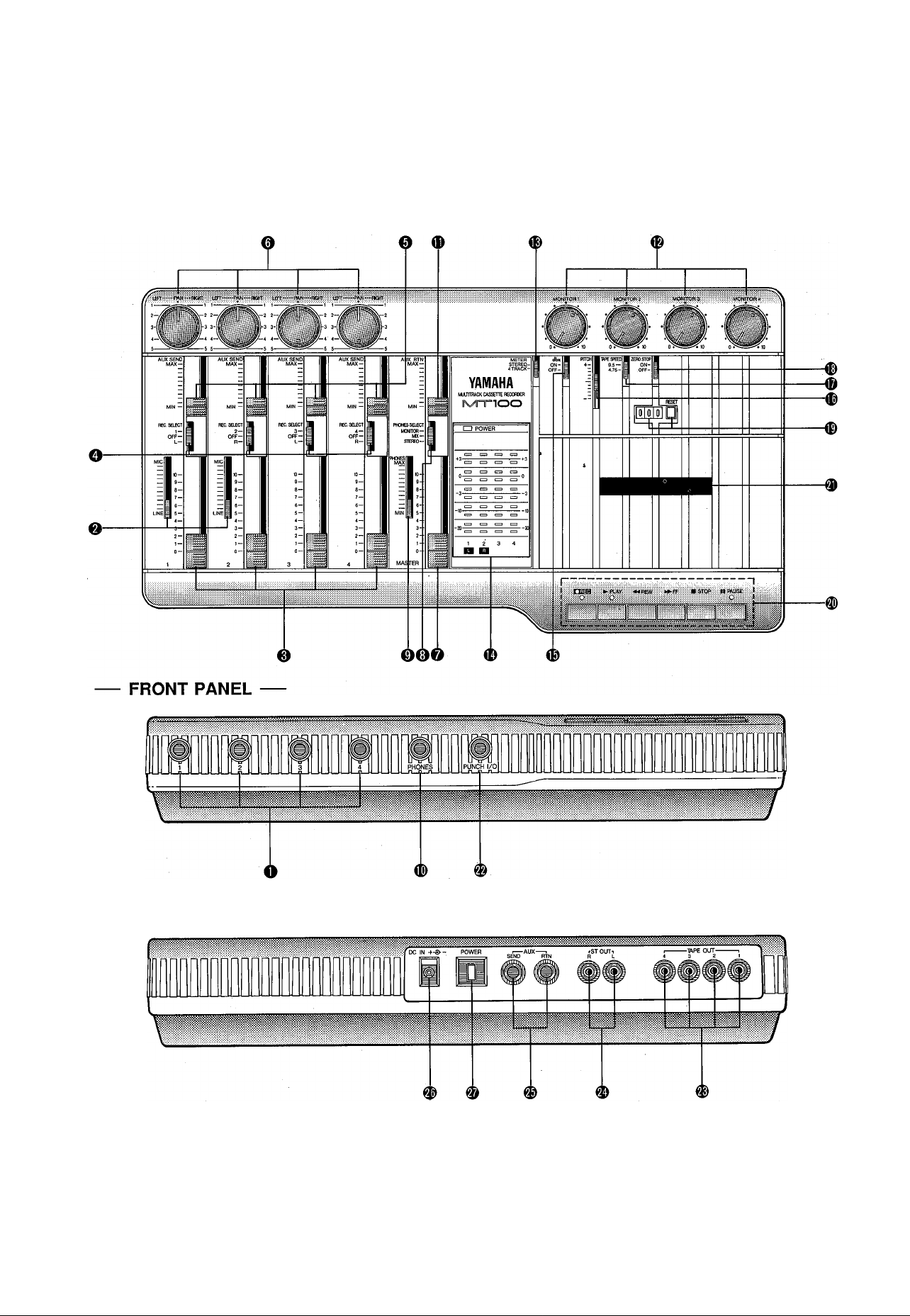
THE CONTROLS AND CONNECTORS
CONTROL PANEL
REAR PANEL
2 MTLOO MULTITRACK CASSETTE RECORDER
Page 5
----
CHANNELS AND TRACKS
The terms "channel” and “track” are used in this operation manual to differentiate between the MT100 mixer section’s four
"channels” and the recorder section’s four “tracks.” “Track” is also used when referring to the four “tracks” actuaiiy recorded on the
tape.
------
O Input Jacks 1 — 4
These four input jacks accept signais from any iine-ievel
source such as an electronic musical instrument or a tape
player.
Inputs 1 and 2 also accept signals from electric musical in
struments such as electric guitars and basses, or micro
phones.
Inputs 1 through 4 are standard monaural 1/4” phone
jacks.
When a source is plugged into one of these jacks, its
signal is sent to the corresponding channel of the MTIOO’s
mixer.
Note: When no source is plugged into an input jack, the
output from the corresponding track of the MTIOO’s
recorder is automatically routed to that channel of
the mixer.
0 MIC/UNE Gain Controls (Channels 1 and 2 only)
The gain controls adjust the sensitivity of the channel-1
and channel-2 inputs to accept a wide range of signal
levels — from line to microphone. The gain controls are
used in conjunction with the channel-1 and channel-2 fad-
ers to set the optimum recording level with a wide range of
sources (see “SETTING RECORDING LEVELS” on page
12).
0 Channel Faders
The channel faders are used to adjust the level (volume)
of the corresponding mixer channel’s signal, whether it
comes from a source plugged into an input jack or from
the MT1 GO’S recorder section. The faders are used to set
up the optimum levels when recording, and to balance
(mix) the sound from the recorder’s tracks when playing
back a recording.
0 AUX SEND Controls
The AUX SEND controls are used primarily when adding
effects such as reverberation or echo to the sound of each
channel or track. The AUX SEND control on each mixer
channel determines the amount of signal from that chan
nel sent to the AUX SEND jack. The AUX SEND jack must
be connected to the input of an external signal processor
such as the YAMAHA R100 Reverb Processor (see “US
ING THÉ AUX ÇEND/RTN LOOP” on page 16).
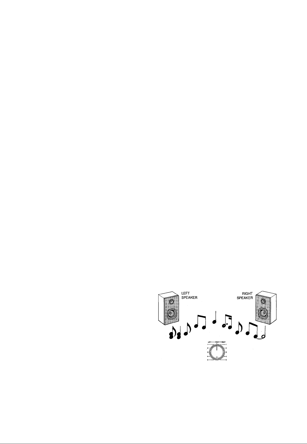
© PAN Controls
The PAN controls assign the signal from the correspond
ing mixer channel to any desired position in the “stereo
sound field.” If a PAN control is set to the maximum
“LEFT” position, the signal from that channel will appear
only at the left-channel MT100 output (ST OUT L). If the
PAN control is set fully RIGHT, the signal will appear only
at the ST OUT R output jack. If a PAN control is set to its
center position, then the signal from that channel will ap
pear equally at both the left- and right-channel outputs,
and the sound will appear at the center of the stereo
sound field (at a point midway between the two stereo
speakers). Other PAN control settings place the sound at
positions roughly corresponding to the PAN control setting
by varying the level of the signal sent to the left- and rightchannel outputs.
The PAN controls can also be used during recording to
assign the signal from several channels to a single track of
the recorder section, or to assign a channel to a differ
ently-numbered recorder track (see “CHANNEL-TOTRACK ASSIGNMENT’ on page 10).
o REC SELECT Switches
The REC SELECT switches are used when recording to
assign (send) the signal from each mixer channel either
directly to the corresponding track of the recorder or to a
different track via the PAN controls (see “CHANNEL-TO-
TRACK ASSIGNMENT” on page 10).
Note: When any of the REC SELECT switches are set to a
position other than OFF, the red indicator LED
above the transport REC button will flash, indicating
that the MT100 is set up to record.
PAN
Page 6

o MASTER Fader
The MASTER fader sets the overall output level of the
MT100 mixer section, and thus the level of the output
signal appearing at the ST OUT jacks. The MASTER fader
also affects recording level when any of the mixer
section’s channels are assigned to the recorder’s tracks
via the PAN controis (see "SETTING RECORDING LEV
ELS” on page 12).
® MONITOR Controls
The four MONITOR controls determine the levei of the
signai from the corresponding recorder tracks which is
sent to the PHONES jack when the PHONES SELECT
switch is set to either “MONITOR” or "MIX.” The MONI
TOR controls are primarily used to set up the optimum
leveis for monitoring recorded tracks while recording new
material (overdubbing).
o PHONES SELECT Switch
The MT100 permits convenient headphone monitoring via
a pair of headphones plugged into the PHONES jack. The
PHONES SELECT switch determines which signals are
sent to the PHONES jack for monitoring.
MONITOR: In this position only the output from the
recorder’s four tracks is sent directly to the PHONES
jack via the four MONITOR controls.
MIX: Both the output from the recorder’s four tracks (via
the MONITOR controls) and the stereo output from
the mixer section are sent to the PHONES jack.
STEREO: Oniy the stereo output from the mixer section is
sent to the PHONES jack.
0 PHONES Control
The PHONES control independently adjusts the level of
the headphone signal, making it simple to set the most
comfortable monitoring ievei.
0 PHONES Jack
Any pair of stereo monitor headphones with an impedance
of between approximately 8 and 40 ohms can be plugged
into this jack. Headphone monitoring is the most conven
ient way to iisten to the MTIOO’s various signais, and we
recommend that you obtain a pair of high-quality monitor
ing headphones for this purpose. The YAMAHA MH100
are ideal.
0 AUX RTN Control
The AUX RTN control determines the levei at which the
signai from an externai signai processor fed by the AUX
SEND jack is returned and mixed in with the MTIOO’s
main stereo output signal. The output from an external
signal processor fed by the AUX SEND jack must be con
nected to the AUX RTN jack (see "USING THE AUX
SEND/RTN LOOP” on page 16).
® METER Switch
The METER switch determines whether the four LED peak
meters display levels from the corresponding recorder
tracks when set to "4 TRACK,” or meters 1 and 2 dispiay
the level of signals appearing at the mixer section’s stereo
outputs (the ST OUT jacks) when the METER switch is set
to "STEREO.” ‘
0 LED Peak Meters
The four LED peak meters accurately display output levels
from the MTIOO’s four recorder tracks when the METER
switch is set to “4 TRACK,” of the first two meters (num
bered 1 and 2) display levels appearing at the mixer
section’s stereo outputs (the ST OUT jacks) when the
METER switch is set to “STEREO.”
The LED peak meters are important for setting up the
optimum recording levels when recording new material
(see “SETTING RECORDING LEVELS” on page 12).
0 dbx ON/OFF Switch
The dbx switch determines whether the MTIOO’s internal
dbx noise reduction system is ON or OFF. For normal
recording and piayback using the MT100, the dbx switch
shouid be turned ON. This provides a significantiy im
proved signal-to-noise ratio (as much as 85 dB) so your
recordings will sound cleaner and have much less tape
hiss.
For dbx noise reduction to be effective, it must be turned
ON both during recording and playback.
The dbx switch may be turned OFF when piaying back
tapes that were recorded on other equipment and which
are not dbx-encoded.
0 PITCH Control
The PITCH control varies tape speed by ±10%, making it
possibie to ’lune” material recorded on the MT100 to
match the pitch of musical instruments, or to slightly
lengthen or shorten the running time of a recording to
meet specific timing requirements. Tape speed is normal
when the PITCH control is set to its center click-stop posi
tion. Tape speed is increased by sliding the control to
wards the “+” end of the scale, and decreased by sliding
the control towards the end of the scale.
4 MTIOO MULTITRACK CASSETTE RECORDER
Page 7

ф ТАРЕ SPEED Switch
The TAPE SPEED switch selects either the standard 4.75cm/sec cassette tape speed, or the MTIOO’s special 9.5cm/sec high tape speed. Use the standard (4.75) speed
when replaying tapes recorded on standard cassette re
corders, or to obtain maximum tape economy. When you
want maximum sound quality, use the high (9.5) tape
speed. The improvement in isound quality provided by the
high tape speed is significant, and we recommend that
you use the high speed for all important recordings.
Ф ZERO STOP Switch
The ZERO STOP switch provides a fast, easy way to lo
cate a specific location on the tape. This is particularly
handy in multitrack recording, since it is necessary to re
peatedly rewind the tape to the same point to record over
dubs (i.e. record a new track while monitoring previously
recorded tracks). To use the ZERO STOP function, set the
tape counter (below) to “000” at the point you wish to
locate by pressing the RESET button. Then, with the
ZERO STOP switch set to ON, the tape will automatically
stop from the rewind or fast forward modes when the
counter “000” position is reached.
Ф Tape Counter and RESET Button
This three-digit tape counter provides a handy index to
tape position. It’s a good idea to write down the counter
readings for important points of a recording, so you can
locate them easily afterwards. The RESET button resets
the counter to “000” at the current tape position.
# Transport Controis
These light-touch electronic transport controls provide
smooth, sure control of all tape transport functions.
Note: Only tracks for which the REG SELEGT switch is set
to a recording position will be recorded when the
REGORD mode is activated.
Note:The REGORD mode cannot be activated if a cas
sette is loaded from which the record-prevention tab
has been removed.
PAUSE: Temporarily stops playback or recording. The or
ange PAUSE indicator LED will light when the
PAUSE mode is active. Press the PLAY button to
disengage the PAUSE mode and continue playback
or recording.
REWIND (REW) & FAST FORWARD (FF): These buttons
cause fast‘winding of the tape in the specified direc
tion.
STOP: Immediately stops the transport from any of its op
erational modes.
® Cassette Compartment
Your cassette tape is loaded here. Use only high-quality
chrome (CrOa) formula cassette tape. Other types of tape
will not provide correct frequency characteristics and mini
mum noise with the MT100.
First flip up the cassette compartment lid (a lifter tab is
provided at the right side of the cover), then insert the tape
with the open end of the cassette (the end at which you
can see the tape) facing the transport controls. Press the
back (closed) edge of the cassette down under the central
retaining finger at the rear of the cassette compartment,
then press the front (open) end down into the mechanism
— GENTLYI Glose the compartment lid when ready.
PLAY: Starts the transport running in the PLAY mode. The
green PLAY indicator LED lights during playback.
RECORD: Press the REG button to enter the “REG/
PAUSE” mode. If all the REG SELEGT switches are
turned OFF, the red REG indicator LED will flash and
the orange PAUSE indicator LED will light. If any of
the REG SELEGT switches are set to a position other
than OFF, both the red REG and orange PAUSE
LEDs will light continuously. In this mode the trans
port is not yet running and recording has not begun.
From the REG/PAUSE mode, press the PLAY button
to actually start the transport running in the REGORD
mode (if any of the REG SELEGT switches are set to
a position other than OFF), or the REGORD-READY
mode (if all the REG SELEGT switches are set to
OFF). The red REG and green PLAY indicator LEDs
both light during recording. The red REG will con
tinue to flash and recording will not occur if none of
the REG SELEGT switches are set to a recording po
sition.
Note: Since the MT100 uses the entire width of the cas
sette tape to record four tracks, the cassette can only
be recorded on one side. If you attempt to flip the
cassette and record on the second side, you will
erase any previously recorded material.
@ PUNCH i/0 Footswitch Jack
An optional YAMAHA FS-1 Footswitch can be connected to
this jack to permit foot-controlled punch-in and punch-out
recording (see “PUNGH-IN/OUT REGORDING” on page
17).
Page 8

»TAPE OUT Jacks
The four TAPE OUT jacks are direct outputs from the cor
responding tracks of the MT100 recorder. These jacks
make it possible to feed the output from the four recorder
tracks to an externai mixing consoie. The TAPE OUT jacks
can also be used to feed each of the recorder’s tracks to
external signal processors, the output of which can then be
returned to the MTfOO’s mixer inputs.
The TAPE OUT jacks are RCA pin types with a nominal
output level of -10 dB into a load of greater than 50 kohms.
I ST OUT R and L Jacks
These are the main outputs from the MT100, delivering the
stereo output signal from the MT100 mixer section. The ST
OUT jacks can be connected to a stereo sound system for
monitoring and listening, or to a second cassette recorder
when recording a stereo “mix” of a multitrack MT100 mas
ter tape. The ST OUT R and L jacks are RCA pin jacks with
a nominal output level of -10 dB when feeding a load of
greater than 50 k-ohms.
IAUX SEND & RTN Jacks
The AUX SEND and RTN jacks make it simple to use an
external signal processor (such as the YAMAHA R100
Reverb Processor) to add effects to MT100 signals. The
AUX SEND jack should be connected to the input of your
signal processor, and the output from your signal processor
should be connected to the AUX RTN jack (see “USING
THE AUX SEND/RTN LOOP” on page 16).
) DC m Jack
The DC output cord from the YAMAHA PA-100 AC Adaptor
supplied with the MT100 should be plugged in here. The
AC Adaptor should be plugged into a convenient AC wall
outlet.
Caution: Use only a YAMAHA PA-100 AC Power Adaptor
to power your MT100. Other AC adaptors can cause
faulty operation, and may even permanently damage
yourMTIOO.
I POWER Switch
Press the POWER switch once to turn power ON, a second
time to turn power OFF. When the power is ON, the
POWER LED above the LED peak meters on the MT100
top panel will light.
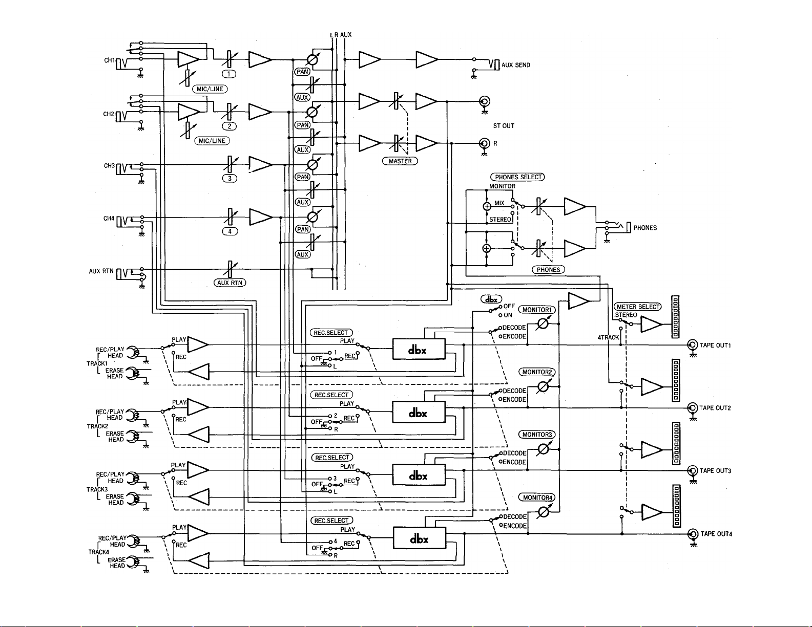
Note: If you are familiar with block diagrams of electronic
equipment, refer to the “BLOCK DIAGRAM” on page
19 for a full overview of the MT100 system.
6 MTIOO MULTITRACK CASSETTE RECORDER
Page 9
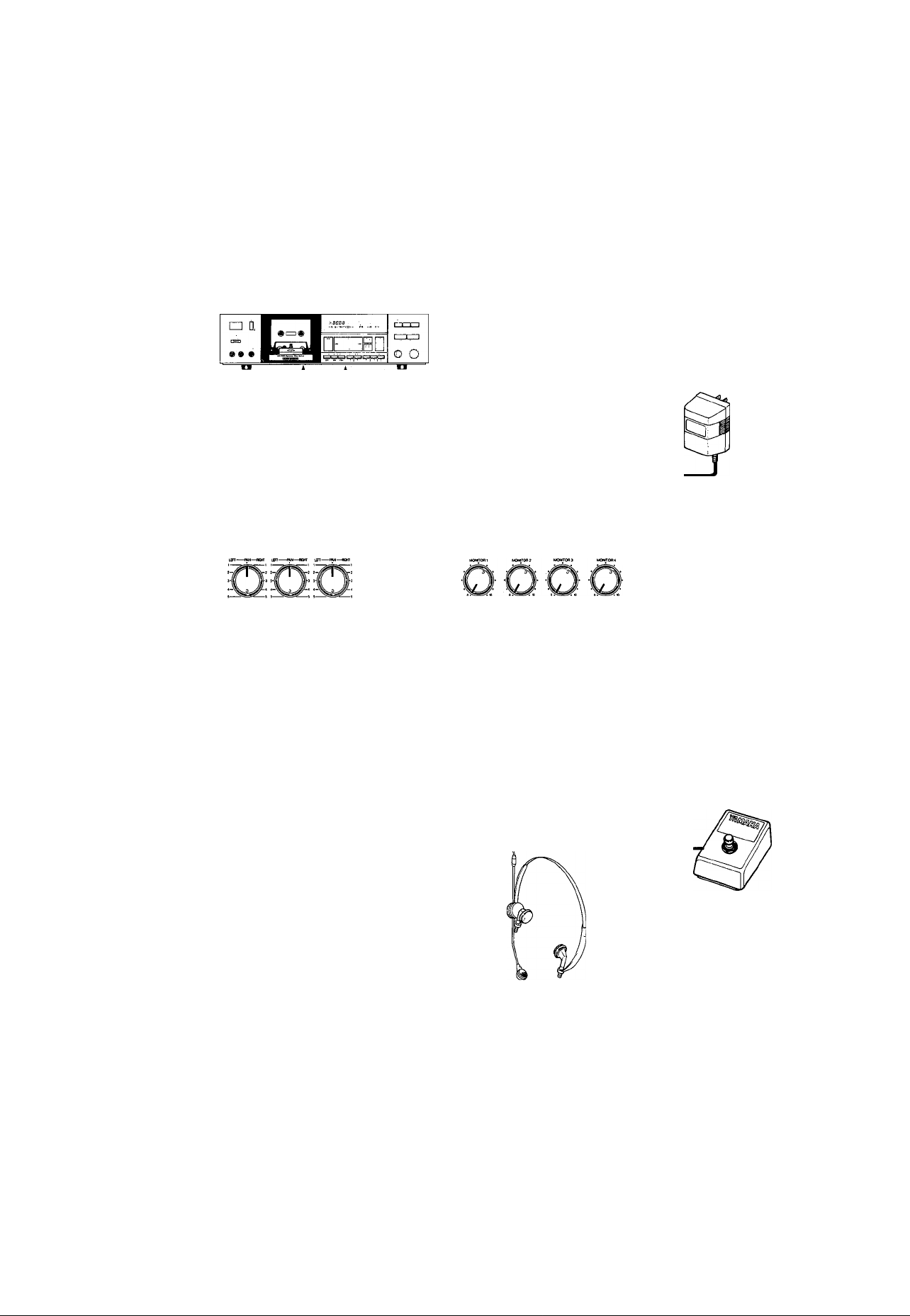
CONNECTION EXAMPLES
BASIC CONNECTIONS
LINE IN L
Stereo cassette deck
to be used for mixdown
Or to a stereo system •
or stereo amplifier
and speakers
STOUT L
^IBT—w
111
OUTPUT
L or R
AUX
RTN
Mnnoo
OQOODOQ
‘ INPUT
AUX
SEND
PUNCH I/O
External effect unit for
reverberation and/or delay
i
-----------------------
------------------
i
i
=J
MT100
AC Adapter
PAI 00
Instruments
(Electric guitar, bass,
keyboard,microphone, etc.)
Make sure the power to all equipment is OFF when making connections.
PHONES
Footswitch
FS-1
Monitor headphones
Page 10
ABOUT CASSETTE TAPES
This unit is designed to be used only with Chrome-
position tape, and will not work properly with Ferrichrome tape formulations. CrOa tape (Bias: HIGH; EQ:
70/ts) should be used. Also, the use of C-120 tapes is
not recommended because they exhibit poorer perfor
mance, and can be the cause of equipment failure.
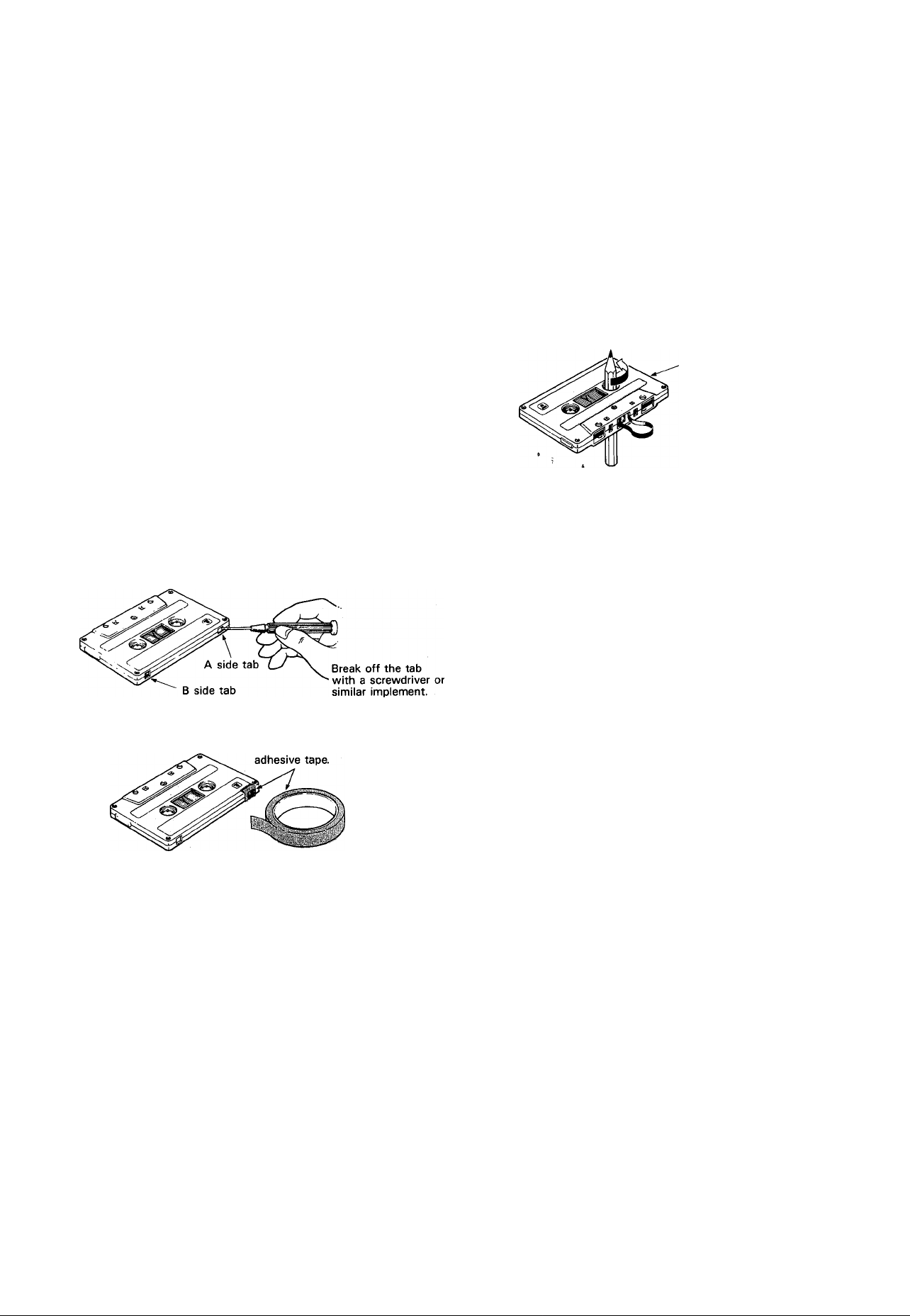
• Preventing accidental erasure of recordings
To keep from inadvertently erasing a prized recording, all
cassette tapes have record protection tabs along the top
edge of the cassette shell. If this tab is broken out using
a screwdriver or any other appropriate implement, it will
not be possible to record on the corresponding side of
the tape. This will protect your recordings from accidental
erasure. For 4-track recording, it's necessary to break out
the tabs for both the A and B sides of the tape.
When you'd like to record over a tape with the tabs
broken out, just cover the holes (where the tabs were)
with tape.
• PREVENTING ACCIDENTAL TAPE ERASURE:
• Taking up tape slack
If the tape is used when it is slack, or some portion of
the tape is out of the cassette shell, there is a risk it
may become tangled around the capstan or pinchroller.
In order to correct this, insert a pencil or ballpoint pen
into the center of one reel, and rotate to take up loose
tape slack.
Cassette shell
• Storing cassette tapes
To prevent tape slack, fit a stopper into the tape or keep
tapes in their cases. Do not store tapes in direct sunlight,
or in places with high heat or humidity, as this may
damage the tapes. Also, keep the tapes away from
magnetic fields, such as near televisions or speakers,
because the recordings can be erased or sonically altered
to some degree.
• RECORDING OVER A TAPE WITH THE TABS BROKEN OUT:
Cover the hole with
8 MTIOO MULTITRACK CASSETTE RECORDER
Page 11

THE RECORDING PROCESS
Recording with the MT100 is a very simple process. All you need is the MT100, a pair of monitor headphones, and an instrument,
microphone, or other signal source.
The multitrack recording process can be basically broken down into the following steps:
1. Record the First Track.
a) Channel-to-track Assignment.
b) Set Record Level.
c) Record.
2. Overdub the Remaining Tracks.
a) Channel-to-track assignment for each overdub.
b) Set record level for each overdub.
c) Record the overdub.
3. Ping-pong and Overdub More Tracks (if necessary).
4. Mixdown.
a) Set up for monitoring the mix.
b) Set up a rough mix and add effects.
c) Finalize and rehearse the mix.
d) Connect the MT100 ST OUT jacks to a stereo casette recorder.
e) Record (from the MT100 to the stereo cassette recorder).
These steps (and what the recording terms mean) will be described in detail below, so its a good idea to read through the foiiowing
sections in sequence in order to get a clear picture of the overall recording process.
Page 12

RECORDING THE FIRST TRACK
STEP 1: CHANNEL-TO-TRACK ASSIGNMENT
The first step in making any recording is to assign the channei to which your instrument or other source is connected to one of the
recorder’s tracks.
Depending on what you are recording, you might want to record a singie instrument or other source to a single track on the recorder,
or you might want to combine several instruments or other sources and record them on a single track. The MT100 offers two
“channel-to-track assignment” methods that can be used individually or combined to give you the track assignments that you need.
Direct ChanneMo-Track Assignment
With this method, an instrument or source connected to one of
the mixer’s channels is fed directly to the correspondingly
numbered track of the recorder. You can record a single track
like this, or up to all four tracks simultaneously.
For direct channel-to-track assignment, the REG SELECT
switch of the channel(s) to be recorded must be set to the
“number” position (1, 2, 3 or 4). For example, if the channel 1
REG SELECT switch is set to “1,” the channel 1 signal will be
sent directly to track 1 of the recorder. This applies in the
same way to all other channels and tracks.
Panned Channet-to-Track Assignment
The panned channel-to-track assignment method makes it
possible to assign several of the mixer’s channels to a single
recorder track, or single mixer channels can be assigned to
different tfack numbers.
Each of the REG SELECT switches has either an “L” or “R”
position. These correspond to the left (L) and right (R) chan
nels of the mixer’s output. If a REG SELECT switch is set to
“L,” for example, any of the mixer’s channels can be assigned
to the correspondingly numbered track by setting its PAN
control fully LEFT. You could assign channel 1 to track 4, for
example, by setting the channel-4 REG SELECT switch to “R”
and the channel-1 PAN control fully RIGHT.
The assignment shown in the diagram below is achieved by
setting the channel-4 REG SELECT switch to “R,” and setting
the PAN controls of channel 1, 2 and 3 fully RIGHT. The
channel-4 PAN control is set fully LEFT to prevent its signal
from reaching track 4 of the recorder.
MIXER SECTION RECORDER SECTION
CHAN. 1
CHAN. 2
CHAN. 3
CHAN. 4
10 MTIOO MULTITRACK CASSETTE RECORDER
TRACK 1
TRACK 2
TRACK 3
TRACK 4
MIXER SECTION
CHAN. 1
CHAN. 2
CHAN. 3
CHAN. 4
RECORDER SECTION
TRACK 1
TRACK 2
TRACK 3
TRACK 4
Page 13

STEP 2: MONITOR SETUP
Once your source is connected to an input channel and that channel is assigned to one of the recorder’s tracks, you should set up your
monitor system so that you can monitor the track as it is recorded.
Headphone Monitoring
Monitoring via a pair of headphones connected to the
PHONES jack offers the greatest flexibility and is recom
mended for generai recording. The PHONES SELECT switch
aiiows you to select the desired signal for monitoring as fol
lows:
MONITOR: In this position oniy the output from the recorder’s
four tracks is sent directly to the PHONES jack via the
four MONITOR controls. The MONITOR controls are
used to set up the desired monitor "mix.” This setup is
ideal for general monitoring while recording because it
allows you to set up a monitor mix independently from
the channel faders. Material already recorded on any of
the recorder’s tracks is delivered to the PHONE jack via
the corresponding MONITOR controls as long as the
REG SELECT switches for the playback channels are
set to OFF. The sound of instruments or other sources
assigned to any of the recorder’s tracks is also delivered
to the PHONES jack via the corresponding MONITOR
controls.
MIX: Both the output from the recorder’s four tracks (via the
MONITOR controls) and the stereo output from the
mixer section are sent to the PHONES jack.
Monitoring via a Sound System with Speakers
It is also possible to use a stereo sound system with speakers
or a pair of powered monitor speakers (such as the YAMAHA
MS101 Monitor Speaker System) connected to the MT100 ST
OUT L ahdjR jacks for monitoring. When monitoring via a
sound system in this way, only the stereo output from the
MT100 mixer section can be monitored. This is the same situ
ation as monitoring via headphones with the PHONES SE
LECT switch set to STEREO. The use of a sound system for
monitoring is therefore not recommended for general record
ing, but is highly recommended for mixdown since it allows
you to monitor your mix under conditions that are closer to the
way your final tape will hopefully be heard — via a stereo
sound system and speakers.
Note:Speakers should not be used for monitoring if you will
be recording via microphones, since the monitor sound
will leak into the microphone(s) and spoil the recording.
STEREO: Only the stereo output from the mixer section is
sent to the PHONES jack. This setting is most useful for
mixdown of a completed multitrack recording, since you
want to hear the mix produced by the mixer section’s
channel faders and any effects applied using the AUX
SEND and RTN controls while mixing. Make sure that
no sources are plugged into any of the mixer’s inputs
while mixing, so that the outputs from the recorder sec
tion are routed to the mixer section’s inputs.
11
Page 14

STEP 3: SETTING RECORDING LEVELS
Setting optimum recording levels is vitally important to achieve the best possible recording quality.
1. Start with the channel fader on the channel to be used set
to its minimum ("0”) position, and the MIC/LINE trim control
(if you are recording via channel 1 or 2) set all the way to
LINE.
2. Once everything is properly set up play the source at the
highest (loudest) level that it will be played while actually
recording.
3. Set the MASTER fader to about “7” or “8” on the scale, and
gradually raise the channel fader until you begin to hear the
source sound and see the LED peak meter come to life. If
your source is an electric instrument (guitar or bass) or a
microphone and you are recording via channel 1 or 2, you
may also have to slide the MIC/LINE trimmer towards the
MIC end of its scale to get a sufficiently high meter reading.
Adjust the channel fader (and MIC/LINE trim control if ap
plicable) so that the meter reading averages between
about "0” and "+3” on the scale. Ideally, the channel fader
should be set at about “7” or "8” on its scale to achieve the
above-mentioned meter reading. This is to ensure the best
possible signal-to-noise ratio and allow plenty of plus and
minus leeway for later adjustment. If the fader setting is
way off, try adjusting the volume control on the instrument
or other*SQurce until you can get the optimum reading with
a fader setting between “7” and “8.”
STEP 4: RECORD
After assigning the input channel to a recorder track, checking the monitor settings and setting the optimum record level for the new
track, you’re ready to record.
1. Make sure that a cassette has been loaded into the cas
sette compartment, and that it is wound to the point at
which you intend to start your recording. It’s a good idea to
press the counter RESET button to set the counter to “000”
at this point so that you can automatically locate the begin
ning of the recording later using the ZERO STOP function.
2. Press the REC button and then the PLAY button to start
recording, wait a few seconds, and start playing.
3. When you’ve finished recording the track, press the STOP
transport button, turn the REC SELECT switch for the track
just recorded OFF, rewind the tape (the tape will stop auto
matically at counter "000” if the ZERO STOP switch is ON).
4. Play back the recording (press the PLAY transport control)
and listen to the track to make sure that everything went as
planned.
Note: When recording the first track it is vital to record
some form of “count-in” prior to actually playing your
instrument! If you haven’t included a one- or twomeasure count-in in your first track, you’ll have a
heck of a time trying to coordinate the beginning of
your second track with the first.
12 MTIOO MULTITRACK CASSETTE RECORDER
Page 15

OVERDUBBING
Overdubbing is the process of recording a new track (or new tracks) whiie monitoring previousiy recorded tracks, if you’re oniy
pianning to record a maximum of four tracks, you can go ahead and overdub the second, third and fourth tracks. If you’re planning
to use the "ping-pong” recording technique to record more than four parts, however, record only up to the third track and then move
on to the ping-pong step (see "PING-PONG RECORDING” on page 14).
1. Plug the instrument or other source to be recorded into an
available channel input.
2. Make sure that the REC SELECTOR switches of previ
ously-recorded tracks are set to OFF so that they aren’t
erased when the new track is recorded.
3. Set up the channel-to-track assignment for the new track.
4. Check your monitor settings to ensure that you can monitor
the previously recorded track(s) as well as the new track to
be recorded (the PHONES SELECT switch should nor-
maiiy be set to MONITOR if you are monitoring via head
phones).
5. Set the recording level for the new track.
6. You can now “rehearse” the overdub without actually re
cording by simply playing back the already-recorded
track(s) and playing the new part.
7. Make sure the tape is rewound to the beginning of the
piece and start recording.
These steps are simply repeated to overdub tracks 3 and 4.
13
Page 16

PING-PONG RECORDING
Ping-pong recording is a technique you can use to squeeze more than just 4 parts onto your 4-track machine.
In ping-pong recording, you can record parts on tracks 1, 2,
and 3, for example, and then re-record these tracks onto track
4, using the mixer controls to set up the right balance between
the 3 original tracks. You now have a “mix” of the first 3 tracks
4, 3 parts on track 3, and 2 tracks available. That’s a total of 9.
Following this procedure it is actually possible to record up to
10 individual tracks without re-recording any single track more
than once (refer to the illustration).
on track 4, and tracks 1, 2, and 3 are available for more
recording. That’s already the'equivalent of 6 'tracks” on your
Note: Ping-ponging is a critical step because the tracks to be
4-track recorder. While mixing the first 3 tracks down onto
track 4 you can also mix in a live instrument via the MT100
mixer section. That would give you 4 parts recorded on track 4
of the tape. With the 3 tracks you stiil have available for re
cording, that’s a total of 7 tracks. Now, if you record only 2 of
the remaining tracks and ping-pong these to track 3 while
mixing in another live instrument, you’ll have 4 parts on tracks
EXAMPLE: Recording tracks "1" through "10" using the Ping- pong process.
Ping-Po ng 1,2 and 3
Rec ord p arts 1, 2
and 3.
TRA CK 1 1
TRA CK 2 2
TRA CK 3 3
TRA CK 4 I 1,2 , 3-f4 I 1, 2 , 3 + 4
to track 4 while add
ing part 4.
Rec ord parts 5 and 6.
5 8 10
6 8 -f 9 8-1-9
^ing-Pong 5 and 6 to
rack 3 while addin g
part 7.
5, 6 -f7 5, 6-1-7 5, 6 -t-7 5, 6 H-7
1,2 , 3-I- 4 1,2 , 3 -r - 4 1,2 , 3 -h 4 1, 2 , 3 - r- 4
A PING-PONG RECORDING EXAMPLE
ping-ponged must be mixed perfectly before you can
go on to recording the subsequent tracks. This is be
cause once they’re ping-ponged and new material has
been recorded on the original tracks, their balance and
individual sound cannot be changed unless you go
back and record the original tracks all over again.
Rec ord part 8.
Move 8 to tra ck 2
while ad ding 9.
Rec ord 10 the last
part.
The following is an example of how you would ping-pong material recorded on tracks 1, 2 and 3 onto track 4.
Here’s how the controls should be set:
•Input Jacks
Make sure that nothing is plugged into any of the mixer’s
input jacks.
•Channel Faders
To begin with, set the channel 1 through 3 faders to about
"7” on their scales, and set the channel-4 fader to “0.”
•REC SELECT Switches
The channel 1 through 3 REC select switches must be set
to OFF, and the channel-4 REC SELECT switch should be
set to “R.”
•MONITOR Controls
Set the channel 1 through 3 MONITOR controls fully
counter-clockwise, and the channel-4 MONITOR control to
about center or a position that will provide the best monitor
ing level.
1. Play back the tape (don't press the REC button yet).
Gradually increase the channel-4 fader setting until you
can hear the tracks you’ve recorded and the channel-4
meter reads around “0” on the scale. Adjust the MONITOR
4 control for the most comfortable monitoring level.
•AUX SEND Controls
Set all four AUX SEND controls to MIN for the time being.
•PAN Controls
Since the channel-4 REC SELECT switch is set to “R,” the
channel 1 through 3 PAN controls bust be rotated full
clockwise (right) to assign the track 1, 2 and 3 signals to
track 4 of the tape. The channel-4 PAN control can be set
to center.
•AUX RTN Control
Set to MIN for the time being.
•PHONES SELECT Switch
Set to MIX so you’ll only hear signals from the MT100 re
corder.
2. Adjust the channel 1, 2 and 3 faders — carefully — until
you get the desired balance between the first three tracks.
You’ll notice that as you adjust the balance between tracks
the channel-4 meter reading might change considerably.
You’ll have to compensate for this as you set up the ping-
pong mix by adjusting the channel 4 fader.
3. When everything is set up perfectly, rewind the tape to the
beginning and start recording. Sit back and wait until the
ping-pong is complete, then stop the recorder. Now play
back the tape and listen to the ping-ponged track carefully.
If something sounds odd, go back and repeat the pingpong process. You can do this as many times as neces
sary until you get it right — then go on to the next step.
14 MTIOO MULTITRACK CASSETTE RECORDER
4. Overdub and, if necessary, ping-pong the remaining tracks.
Page 17

MIXDOWN
Mixdown is the final stage in the recording process at which you transform your multitrack master tape into a mono or stereo master
tape that is the final creative product. The process involves re-recording the multitrack tape, via the MTIOO’s mixer, onto a
conventional stereo tape deck while you finely balance the tracks to achieve just the right sound. Tracks can be faded in or out as
required, and refinements such as overall reverberation or equalization can be added using external signal processing equipment.
The mixer’s PAN controls can be used to position each track at the appropriate location in the stereo image, and you can even want
pan a sound from one channel to the other for dramatic effect.
Here’s how your system should be set up:
•Input Jacks
Make sure that nothing is plugged into any of the mixer’s
input jacks.
• Channel Faders
Set all channel to “0.”
•RFC SELECT Switches
All REG SELECT Switches to OFF.
•AUX SEND Controls
Set all four AUX SEND controls to MIN for the time being.
• PAN Controls
Start with all PAN controls set to center.
MASTER Fader
Set to about “7” or "8” on the scale.
•AUX RTN Control
Set to MIN for the time being.
• PHONES SELECT Switch
Set to STEREO if you’ll be mixing using headphones. We
recommend using an external sound system or a pair of
powered monitor speakers (such as the YAMAHA MS101
Monitor Speaker System) for mixdown, in which case the
PHONES SELECT switch setting doesn’t matter.
•MONITOR Controls
Set all MONITOR controls fully counter-clockwise.
• METER Switch
4 TRACK.
•dbx Switch
If you started recording with the dbx switch ON, leave it
ON. If OFF, it should stay OFF.
1. Sit in a comfortable, central position in front of your monitor
speakers.
2. Listen to, evaluate, and adjust the sound of each track indi
vidually. This simply means raising the fader of a single
track, adding effects or other signal processing as required,
then repeating*the process on the next track until all tracks
have been carefully checked. If you have an external signal
processing device such as the YAMAHA R100 Reverb
Processor connected into the MTIOO’s AUX SEND/RTN
loop as described in the following section (“USING THE
AUX SEND/RTN LOOP), it’s a simple matter to select the
desired effect on your signal processor and add the re
quired amount of effect to each track using the AUX SEND
controls. The AUX RTN control must also be set to an ap
propriate level.
3. When all tracks have been individually checked, bring all
channel faders up to about "T or "8” on the scale and play
back the tape. Adjust the faders for the best overall bal
ance. Now adjust the PAN controls to place each track at
the desired location in the stereo sound field. Now listen
carefully — too much or too little reverb on any track?
Readjust the AUX SEND controls to achieve the desired
effect. Balance not quite right? Keep readjusting until you
are satisfied. You should also rehearse any fades or pans
you plan to do while actually recording the mix.
4. When you’re sure everything is ready, prepare to actually
record the mix. To do this you’ll have to connect the MT100
ST OUT jacks to the inputs of a stereo cassette recorder.
Plug your monitor headphones into the stereo cassette
deck phones jack if you want to listen as you record the
mix, or simply leave them connected to the MT100
PHONES jack and listen with the PHONES SELECT switch
set to STEREO. Use the stereo cassette deck record level
control(s) and, if necessary, the MT100 MASTER fader to
set the optimum record level, then go ahead and record.
The MT100 MASTER fader can also be used to add a slow
fade at the end of the piece.
15
Page 18
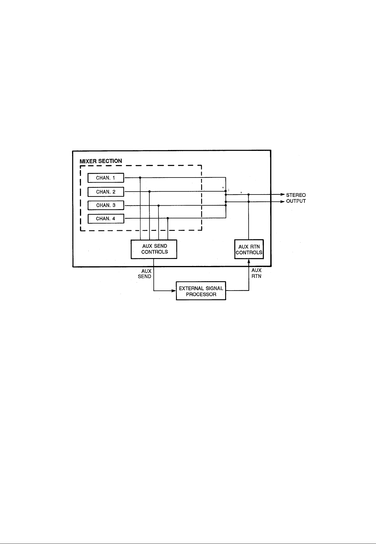
USING THE AUX SEND/RTN LOOP
The MTIOO’s AUX SEND controls function like a secondary mixer that derives its input signals from the main mixer's four channels
and combines them into a mono signal which is delivered via the AUX SEND jack (refer to the diagram below). You can use the AUX
send controls to create an “effect mix” which is entirely independent of the main mix, thus applying the required degree of effect to
each channel signal. The AUX SEND signal is sent to the input of an external signal processor (reverb, echo or other effect device),
and the output from the signal processor is returned to the AUX IN Jack. The level of the signal received at the AUX IN jack can be
adjusted using the AUX RTN control, and the resulting signal is combined with the MTIOO’s main stereo output signal.
Since the returned effect signal is combined with the mixer’s stereo output signal, the AUX SEND/RTN loop is most ideally suited to
adding effects to individual tracks during the final mixdown process.
Note: Since the AUX SEND/RTN loop returns the effect signal
to the mixer section’s stereo outputs, effects can be
added to channels during ping-pong recording as long
as the panned channel-to-track assignment method is
used. The AUX SEND/RTN loop cannot be used to add
effects when recording tracks which have been as
signed using the direct channel-to-track assignment
method.
16 M.T100 MULTITRACK CASSETTE RECORDER
Page 19

PUNCH-IN/OUT RECORDING
Punch-in/out recording makes it possible to re-record a short segment of an otherwise perfect track in order to correct a mistake or
“brush up” an important passage. You "punch-in" at the point where you begin recording the new segment, and “punch-out” at the
end of the new segment so that the previously-recorded material is not erased.
Punch-in/out Using the REC SELECT Switches
1. Start the deck running — a few measures before the sec
tion to be re-recorded begins — in the record-ready mode
by pressing the REC button and then the PLAY button with
all track REC SELECT switches set to OFF. The red REC
LED will flash Indicating that the transport is in the recordready mode. The PHONES SELECT switch should be set
to MONITOR so you can hear all the tracks.
2. At a convenient break in the track switch the track to be
corrected to the record mode (punch-in by switching the
REC SELECT switch for that track to the appropriate rec
ord position) and start playing the new material to be re
corded. The REC LED will light continuously as soon as
the REC SELECT switch is set to a record position.
3. At the end of the re-recorded segment switch the track
back to the play mode (punch-out by switching the REC
SELECT switch for that track to OFF). The red REC LED
will begin to flash.
TRACK 1
TRACK 2
TRACKS
TRACK 4
All tracks monitored In PLAY
BACK mode (the deck is In the
REC mode, but the track REC
SELECT switches are set to
OFF).
The record mode Is engaged for
track 3 only when the track 3
REC SELECT switch is set to
an ON position.
Footswitch Punch-in/out
1. Plug a YAMAHA FS-1 (optional) footswitch into the MT100
PUNCH I/O jack.
2. Set the .REC SELECT switch for the track to be punched-in
to the appropriate record position, and press the REC but
ton to activate the rec/pause mode. The red REC LED
should flash Instead of lighting continuously. If the red REC
LED lights continuously, press the footswitch once so that it
flashes; =
3. Press the PLAY button to start the transport running in the
record-ready mode.
4. Press the footswitch to punch-in. The red REC LED will
light continuously.
5. Press the footswitch a second time to punch-out. The red
REC LED will begin to flash.
STOP
Begin playback
c>
It's a good Idea to actually start playing a little
before the punch-in point.
17
Page 20

MAINTENANCE
As a good general rule, the tape heads, pinchroller and cap
stan should be cleaned before each recording, thus ensuring
the best audio quaiity.
After the deck has been used for a period of time, the heads,
pinchroller, and capstan will become dirty. This increases
noise and uneven rotation, leading to a deterioration in sound
quality. Therefore, periodic cleaning and demagnetization is
necessary for preserve optimai audio performance.
Use cotton swabs and aicohoi or head cleaning fluid (available
in most aii audio stores) to clean the heads, capstan, and
pinchroller. Keeping the heads ciean is essential for good re
cordings. For demagnetization, use a high quality head
demagnetizer, and foilow the instructions carefuiiy.
Capstan
Erase head
Rec/Play head
! It's important to keep all parts clean!
Pinchroller
18 MTIOO MULTITRACK CASSETTE RECORDER
Page 21
ш
Г'
О
О
D
S
О)
Page 22

SPECIFICATIONS
TAPE TRANSPORT
Tape Type
Heads
Tape Speed
Pitch Control
Wow & Flutter
Rewind Time
Motor
CONNECTORS
Input 1 & 2 Input Impedance 10 k-ohms
Input 3 & 4
Aux Return
Stereo L & R
Phones Out
Tape Out 1 to 4 Output Impedance 1 k-ohm
Aux Send
Chrome (70 mIcrosec. EQ)
4-channel Permalloy rec/play head
4-channel ferrite erase head
4.75 cm/sec., 9.5 cm/sec.
± 10%
Less than 0.05% WRMS
Approx. 100 sec., for C-60 tape
DC servo motors (2)
Rated Input Level
Max. Input Level
Min. Input Level
Input Impedance 10 k-ohms
Rated Input Level
Min. Input Level
Input Impedance 10 k-ohms
Rated Input Level -10 dB (fader nominal)
Min. Input Level -16 dB (fader max.)
Output Impedance 1 k-ohm
Load Impedance Greater than 10 k-ohms
Rated Output Level
Load Impedance 8 to 40 ohms
Max. Output Level
Load Impedance Greater than 10 k-ohms
Rated Output Level -20 dB into 50 k-ohms
Output Impedance 1 k-ohm
Load Impedance
Rated Output Level -10 dB into 50 k-ohms
-10 dB to -50 dB (fader nominal)
+ 10 dB (gain control min.)
-56 dB (gain control,, fader max.)
-10 dB (fader nominal)
-16 dB (fader max.)
-10 dB into 50 k-ohms
100 mW + 100 mW/40 ohms
Greater than 10 k-ohms
ELECTRICAL SPECIFICATIONS
Frequency Response
S/N ratio
Distortion
Channel Separation
Erasure Ratip
Noise Reduction
40 Hz to 18 kHz, ± 3 dB at 9.5 cm/sec.
40 Hz to 12.5 kHz, ±3 dB at 4.75 cm/sec.
85 dB, dbx ON, IHF-A
Less than 1%, 315 Hz
Greater than 55 dB at 1 kHz
Greater than 70 dB at 1 kHz
dbx *
GENERAL
Power Requirements
(PA-100 AC Adapter)
Dimensions (WxHxD)
Weight
' dbx is a trademark of dbx Incorporated.
U.S. & Canadian Models: 120 V AC, 60 Hz
General Model: 220/240 VAC, 50/60 Hz
382 X 65 X 205 mm (15" x 2-1/2” x 8")
2.5 kg (5.5 lbs)
OdB = 0.775 Vr.m.s.
All specifications subject to change without notice.
20 MTIOO MULTTTRACK CASSETTE RECORDER
Page 23

ENREGISTREUR DE CASSETTES MULTIPISTE
MH
MANUEL D'INSTRUCTIONS
Page 24

FELICITATIONS!
Votre enregistreur de cassettes multipiste MTIOO est un outil créatif, peu commun qui vous permettra
de travailler avec le son de nombreuses manières différentes. Aucun autre enregistreur de cassettes
multipiste offre la simplicité directe et l’aisance d’utilisation du MTIOO. Que vous ayez besoin
d’enregistrer des instruments acoustiques et des voix au moyen de microphones, ou des sources et
instruments électroniques directement connectés, ou encore un mélange créatif des deux, le MTIOO
vous permet de créer votre propre son sans problème et avec la plus grande aisance. Vous pouvez
tout simplement enregistrer et remélanger quatre pistes, ou utiliser la technique de l’enregistrement
multipiste en “ping-pong” pour enregistrer individuellement jusqu’à dix parties indépendantes,
ajoutant le son couche par couche jusqu’à ce que vous ayez créé l’arrangement et la texture que
votre imagination demande. Le MTIOO est aussi simple à utiliser seul qu’avec un groupe. Et parce
que c’est un YAMAHA, vous avez la certitude que le MTIOO vous donnera la qualité sonore et les
performances générales les meilleures qu’il soit possible d’obtenir. Afin d’utiliser au mieux les in
nombrables fonctions du MTIOO et d’en obtenir des performances maximales, nous vous suggérons
de lire très attentivement ce manuel d’instructions et de le ranger dans un endroit sûr afin de pouvoir
vous y référer plus tard.
-TABLES DES MATIERES
PRECAUTIONS.......................................................................................................23
COMMANDES ET CONNECTEURS
EXEMPLES DE CONNEXIONS ............................................................................ 29
CHOIX ET MANIPULATIONS DES CASSETTES..................................................30
METHODE D’ENREGISTREMENT........................................................................31
ENREGISTREMENT DE LA PREMIERE PISTE ...................................................32
ETAPE 1: AFFECTATION CANAL/PISTE
ETAPE 2: PREPARATION DU SYSTEME DE MONITORING
ETAPE 3: REGLAGE DES NIVEAUX D’ENREGISTREMENT
ETAPE 4: ENREGISTREMENT
SURMIXAGE
ENREGISTREMENT EN PING-PONG
EXEMPLE D’UN ENREGISTREMENT EN PING-PONG
MIXDOWN .............................................................................................................. 37
UTILISATION DE LA BOUCLE TRANSMISSION/RETOUR.................................38
ENREGISTREMENT PUNCH-IN/PUNCH-OUT .....................................................39
ENTRETIEN.......................................................................................................... 40
SCHEMA DE PRINCIPE........................................................................................ 41
SPECIFICATIONS
...
...................................................................................................... 35
...............
....................................................................................42
...................................................................
........................................................
.........................
.........................
........................................................................
..................................................................
..................................
24
32
33
34
34
36
36
Page 25

PRECAUTIONS
1. EVITER CHALEUR, HUMIDITE, POUSSIERE ET
VIBRATIONS EXCESSIVES
Ne pas placer l’appareil là où il pourrait être soumis à des
températures ou une humidité excessives, comme par
exemple à proximité d’un radiateur, d’un calorifère, etc.
Eviter également les endroits particulièrement poussiéreux
ou soumis à des vibrations qui pourraient provoquer des
dommages mécaniques.
2. EVITER LES CHOCS
Des chocs physiques violents peuvent endommager
l’appareil. Par conséquent le manipuler avec soin.
NE PAS OUVRIR L’APPAREIL ET NE PAS ES
SAYER DE LE REPARER OU DE LE MODIFIER
SOI-MEME
Ce produit ne contient pas de pièces réparables par
l’utilisateur. Pour l’entretien et les réparations, toujours
contacter un personnel YAMAHA compétent. Le fait
d’ouvrir l’appareil et/ou d’altérer les circuits internes annul
erait la garantie.
AVANT DE PROCEDER AUX CONNEXIONS OU
AUX DEBRANCHEMENTS, CONFIRMER QUE
L’APPAREIL EST HORS TENSION
Avant de brancher ou de débrancher les cordons toujours
mettre l’appareil hors tension. Cette démarche est impor
tante, car elle permet d’éviter tout dommage à l’appareil,
ainsi qu’aux autres composants raccordés.
6. NETTOYER L’APPAREIL AVEC UN CHIFFON
DOUX ET SEC
Ne jamais utiliser de solvants, tels que la benzine ou un
dissolvant, pour nettoyer l’appareil. L’essuyer simplement
avec un chiffon doux et sec.
7. TOUJOURS UTILISER LA SOURCE D’ALIMENTA
TION ADEQUATE
Le MT100 doit être alimenté en utilisant exclusivement
l’adaptateur secteur YAMAHA PA-100 fourni. L’utilisation
de tout autre adaptateur pourrait endommager
sérieusement le MT100.
8. MAINTENIR LES TETES ET LE PASSAGE DE LA
BANDE.PROPRES
Afin de toujours obtenir des performances élevées et une
bonne qualité sonore du MT100, il est très important de
nettoyer régulièrement les têtes et le passage de la bande
(idéalement parlant avant chaque séance
d’enregistrement). Pour ce faire utiliser un kit de nettoyage
spécialement conçu pour être utilisé avec des appareils à
cassettes.
9. N’UTILISER QUE DES CASSETTES AU CHROME
DE QUALITE SUPERIEURE
Le MT100 a été conçu pour être utilisé avec des cassettes
Cr02 (chrome) et ses performances seront moindre avec
un autre type de cassette. Toujours choisir des cassettes
d’une marque de confiance.
MANIPULER PRECAUTIONNEUSEMENT LES
CORDONS
Brancher et débrancher les cordons, le cordon
d’alimentation secteur y compris, en saisissant ie con
necteur, jamais en tirant sur le cordon.
23
Page 26

COMMANDES ET RACCORDEMENTS
PANNEAU DE COMMANDE
PANNEAU AVANT
PANNEAU ARRIERE
------
24 ENREGISTREUR DE CASSETTES MULTIPISTE MTIOO
Page 27

CANAUX ET PISTES
Le terme “canal” et le terme “piste” ont été utilisés dans ce manuel d’instructions pour différencier les quatre “canaux” de l’étage
mélamgeur et les quatre “pistes” de l’étage enregistreur du MT100. Le terme “piste” est également utilisé pour désigner les quatre
“pistes” effectivement enregistrées sur la bande.
O Bornes d’entrée 1 à 4
Ces quatre bornes d’entréé acceptent des signaux en
provenance de n’importe quelle source de niveau de ligne,
comme par exemple un instrument de musique élec
tronique ou un lecteur de cassette. Les entrée 1 et 2 ac
ceptent également des signaux en provenance
d’instruments de musique électriques tels que guitares et
basses, ou en provenance de microphones. Les entrées 1
à 4 sont des prises audio monaurales standard de 1/4".
Lorsqu’une source est connectée à une de ces prises, ses
signaux sont transmis au canal correspondant de l’étage
mélangeur du MT100.
Remarque; Lorsque il n’y a pas de source connectée à
une borne d’entrée, la sortie de la piste correspon
dante de l’étage enregistreur du MT100 est automa
tiquement dirigée vers le canal correspondant de
l’étage mélangeur.
O Commandes de gain (MIC/LINE) (canal 1 et canal
2 uniquement)
Les commandes de gain permettent de régler la sensibilité
des entrées du canal 1 et du canal 2 afin qu’elles puissent
accepter des signaux ayant des niveaux très variés, du
niveau de ligne au niveau de microphone. Les comman
des de gain sont utilisées conjointement aux
potentiomètres du canal 1 et du canal 2 afin de régler le
niveau d’enregistrement optimal pour une grande variété
de sources (voir “REGLAGE DES NIVEAUX
D’ENREGISTREMENT’ à la page 34).
0 Potentiomètres de canal
Les potentiomètres de canal sont utilisés pour régler le
niveau (volume) du signal du canal correspondant de
l’étage mélangeur, qu’il provienne d’une source connectée
à une prise d’entrée ou de l’étage enregistreur du MT100.
Les potentiomètres sont utilisés pour obtenir les niveaux
optima pendant l’enregistrement et pour équilibrer (mixer)
le son en provenance des pistes de l’étage enregistreur
pendant la lecture d’un enregistrement.
0 Commandes de transmission auxiliaire (AUX
SEND)
Les commandes AUX SEND servent principalement lors
de l’addition d’effets, tels que les effets de réverbération ou
d’écho, au son de chaque canal où piste. La commande
AUX SEND de chaque canal de l’étage mélangeur
détermine la partie du signal de ce canal qui sera trans
mises à la prise AUX SEND. La prise AUX SEND doit être
reliée à l’entrée d’un processeur de signaux externe,
comme par exemple le processeur de réverbération
YAMAHA RI 00 (voir “UTILISATION DE LA BOUCLE
TRANSMISSION/RETOUR” à la page 38).
0 Commandes panoramiques (PAN)
Les commandes PAN affectent le signal en provenance du
canal correspondant de l’étage mélangeur à la position
souhaitée dans le "champ sonore stéréo”. Si une com
mande PAN est tournée à fond sur la position “LEFT”
(gauche), le signal de ce canal ne sera appliqué qu’à la
sortie de canal gauche (ST OUT L) du MT100. Si une
commande PAN est tournée à fond sur la position “RIGHT”
(droite), le signal ne sera appliqué qu’à la sortie ST OUT R.
Si une commande PAN est mise sur la position centrale, le
signal de ce canal sera appliqué d’une manière égale aux
sorties de canal gauche et de canal droit et le son
apparaîtra au centre du champ sonore stéréo (en un point
à égale distance des deux enceintes acoustiques). Les
autres réglages des commandes PAN placent le son sur
une position correspondant approximativement au réglage
des commandes PAN, et ce en variant le niveau du signal
transmis aux sorties de canal gauche et de canal droit. Les
commandes PAN peuvent également être utilisées pen
dant l’enregistrement pour affecter les signaux en prove
nance de plusieurs canaux à une seule piste de l’étage
enregistreur, ou pour affecter un canal à une piste de
l’étage enregistreur ayant un numéro différent (voir "AF
FECTATION CANAL/PISTE” à la page 32).
ENCEINTE
DROITE
O Sélecteurs d’enregistrement (REC SELECT)
Les sélecteurs REC SELECT sont utilisés pendant
l’enregistrement pour affecter (transmettre) les signaux en
provenance de chaque canal de l’étage mélangeur, soit di
rectement à la piste correspondante de l’étage enregis
treur, soit à une piste différente via les commandes PAN
(voir “AFFECTATION CANAL/PISTE” à la page 32).
Remarque: Lorsqu’un des sélecteurs REC SELECT est
mis sur une position autre que “OFF”, le témoin à
LED rouge situé au-dessus de la touche REC se met
à clignoter pour indiquer que le MT100 est prêt pour
enregistrer.
25
Page 28

O Potentiomètre principal (MASTER)
Le potentiomètre MASTER permet de régler le niveau de
sortie d’ensembie de l’étage mélangeur du MT100 et, par
conséquent, le niveau du signal de sortie appliqué aux
prises ST OUT. Le potentiomètre MASTER règle égale
ment le niveau d’enregistrement lorsque l’un des canaux
de l’étage mélangeur est affecté aux pistes de l’étage en
registreur, via les commandes PAN (voir "REGLAGE DES
NIVEAUX D’ENREGISTREMENT’’ à la page 34).
® Commandes de monitoring (MONITOR)
Chacune des quatre commandes MONITOR détermine le
niveau du signal de la piste correspondante de l’étage en
registreur qui est transmis à la prise PHONES lorsque le
sélecteur PHONES SELECT est sur la position "MONI
TOR” ou "MIX”. Les commandes MONITOR servent princi
palement à régler les niveaux optima pour le monitoring
des pistes enregistrées pendant i’enregistrement de nou
veaux matériaux (surmixage).
@ Sélecteur de casque (PHONES SELECT)
Le MT100 permet le monitoring, via un casque d’écoute
stéréo connecté à la prise PHONES. Le sélecteur
PHONES SELECT détermine quels signaux seront trans
mis à la prise PHONES pour être contrôiés.
MONITOR: Dans cette position seule la sortie des quatre
pistes de l’étage enregistreur; est transmise directe
ment à ia prise PHONES via les quatre commandes
MONITOR.
MIX: La sortie des quatre pistes de l’étage enregistreur
(via les commandes MONITOR) et la sortie stéréo de
i’étage mélangeur sont transmises à la prise
PHONES.
STEREO: Seuie la sortie stéréo de l’étage mélangeur est
transmise à la prise PHONES.
0 Commande de casque (PHONES)
La commande PHONES règle indépendamment le niveau
du signal de casque d’écoute, permettant ainsi d’obtenir fa
cilement le niveau de contrôle le plus confortable.
® Prise de casque (PHONES)
Un casque d’écoute ayant une impédance comprise entre
8 et 40 ohms peut être connecté à cette prise. Le monitor
ing par casque est le moyen le plus pratique d’écouter les
divers signaux du MT100, et dans ce but nous préconisons
vivement i’achat d’un casque d’écoute de bonne quaiité.
Le YAMAHA MH 100 est idéal.
<D Commande de retour auxiliaire (AUX RTN)
La commande AUX RTN détermine le niveau auquel le
signal en provenance d’un processeur de signaux externe
transmis par la prise AUX SEND sera renvoyé et mélangé
au signal de sortie stéréo principal du MT100. La sortie
d’un processueur de signaux externe transmise par la prise
AUX SEND doit être reliée à ia prise AUX RTN (voir “UTILI
SATION DE LA BOUCLE TRANSMISSION/RETOUR” à la
page 38).
® Sélecteur d’affichage (METER)
Le sélecteur METER détermine si les quatre indicateurs de
crête à LED afficheront le niveau des pistes correspondan
tes de l’étage enregistreur, lorsqu’il est mis sur ia position
“4 TF(ACKS”, ou si les indicateurs 1 et 2 afficheront le
niveau des signaux apparaissant aux sorties stéréo (prises
ST OUT) de l’étage mélangeur, lorsqu’il est mis sur “STE
REO”.
® Indicateurs de crête à LED
Les quatre indicateurs de crête à LED affichent d’une
manière précise les niveaux de sortie des quatre pistes de
l’étage enregistreur du MT100 lorsque le sélecteur METER
est mis sur la position “4 TRACK”. Les deux premiers
indicateurs (numéros 1 et 2) affichent le niveau des sorties
stéréo (prises ST OUT) de l’étage mélangeur lorsque le
sélecteur METER est mis sur ia position "STEREO”. Les
indicateurs de crête à LED jouent un rôie important iors du
réglage des niveaux d’enregistrement optima pour
l’enregistrement de matériaux nouveaux (voir “REGLAGE
DES NIVEAUX D’ENREGISTREMENT’ à la page 34).
® Interrupteur dbx (ON/OFF)
L’interrupteur dbx commande l’activation/désactivation du
circuit interne de réduction du bruit dbx du MT100. Pen
dant la lecture ou l’enregistrement normal à l’aide du
MT100, l’interrupteur dbx doit être mis sur “ON”. Ceci per
met d’obtenir un rapport signai/bruit considérabiement
amélioré (jusqu’à 85 dB) de sorte que ies enregistrements
seront plus clairs, avec très peu de sifflement de bande.
Pour que le système de réduction de bruit dbx soit efficace,
il doit être activé aussi bien pendant l’enregistrement et
que pendant la lecture. L’interrupteur dbx doit être mis sur
“OFF” pendant la lecture de bandes enregistrées sur un
autre appareil et non codées dbx.
26 ENREGISTREUR DE CASSETTES MULTIPISTE MTIOO
Page 29

ф Commande de vitesse de défilement (PITCH)
La commande PITCH fait varier la vitesse de défilement de
la bande de +10%, ce qui permet “d’accorder” ies
matériaux enregistrés avec le MT100 en fonction de la
hauteur tonale d’instruments de musique, ou de
légèrement prolonger ou réduire le temps de passage d’un
enregistrement à des fins de synchronisation. La vitesse
de défilement est normale lorsque la commande PITCH est
à la position centrale marquée par un déclic. Pour
accélérer la vitesse de défilement faire coulisser ia com
mande vers l’extrémité "-ь” de l’échelle et pour la réduire la
faire coulisser vers i’extrémité
Ф Sélecteur de vitesse de défilement (TAPE SPEED)
Le sélecteur TAPE SPEED permet de sélectionner soit la
vitesse de défilement standard de 4,75 cm/sec, soit la
vitesse spéciale du MT100 de 9,5 cm/sec. Utiliser ia
vitesse standard (4,75) pour la lecture de bandes
enregistrées sur magnétocassettes standards ou pour des
raisons d’économie de bande. Utiliser la vitesse élevée
(9,5) pour obtenir une meilleure qualité sonore.
L’amélioration de la qualité sonore que donne la vitesse de
défilement élevée est assez importante et nous
préconisons d’utiliser cette vitesse pour tous les enregistre
ments importants.
Ф Commande d’arrêt sur zéro (ZERO STOP)
La commande ZERO STOP permet de retrouver rapide
ment un point spécifique d’une bande. Cette fonction est
particulièrement pratique dans le cas d’un enregistrement
muitupiste du fait qu’il est nécessaire de rembobiner con
stamment la bande jusqu’au même point pour surmixer (à
savoir: enregistrer une nouveiie piste tout en monitorant les
pistes précédemment enregistrées). Pour utiliser la fonc
tion ZERO STOP, mettre le compteur de bande (au-des
sous) à “000” sur le point qui doit être retrouvé en appuyant
sur la touche RESET. Ensuite, la commande ZERO STOP
étant mise sur “ON”, la bande s’arrêtera automatiquement
lorsque le compteur atteint “000” en modes de rembob
inage ou d’avance rapide.
I Commandes de défilement
Ces commandes électroniques à effieurement permettent
un contrôle sûr et régulier de toutes ies fonctions de
défilement de la bande.
Lecture (PLAY): Lance le défilement de la bande en mode
de lecture. Le témoin à LED vert PLAY reste aliumé
pendant ia lecture.
Enregistrement (REC): Appuyer sur la touche REC pour
passer au mode “REC/PAUSE”. Si tous les
sélecteurs REC SELECT sont sur la position “OFF”,
ie témoin à LED rouge REC ciignote, aiors que ie
témoin orange PAUSE reste aiiumé continueiiement.
Si iin des sélecteur REC SELECT est mis sur une
position autre que “OFF”, les deux témoins à LED,
rouge REC et orange PAUSE, resteront aliumés
continuellement. Dans ce mode la bande ne défile
pas et l’enregistrement n’a pas encore commencé.
Lorsque i’appareii est en mode REC/PAUSE, ap
puyer sur la touche PLAY pour lancer effectivement
le défilement de la bande en mode enregistrement (si
un des sélecteurs REC SELECT est mis sur une
position autre que "OFF”), ou en mode prêt à
i’enregistrement (si tous ies sélecteurs REC SELECT
sont mis sur la position ’OFF”). Les témoins à LED
rouge REC et vert PLAY restent aiiumés pendant
i’enregistrement. Le témoin rouge REC continuera
de clignoter et l’enregistrement ne se fera pas si
aucun des sélecteurs REC SELECT n’est sur une
position d’enregistrement.
Remarque: Seuies les pistes dont le sélecteur REC SE
LECT correspondant est mis sur une position
d’enregistrement seront enregistrée lorsque le mode
d’enregistrement est activé.
Remarque: Le mode d’enregistrement ne peut pas être
activé si une cassette sans languette de protection
est mise en piace.
I) Compteur de bande et touche de remise à zéro
(RESET)
Ce compteur de bande à trois chiffres permet de repérer
faciiement la position de la bande. Il est conseillé de noter
les indications du compteur pour tous ies points importants
d’un enregistrement afin de pouvoir ies retrouver faciie
ment pius tard. La touche RESET permet de remettre ie
compteur à “000” sur la position à laquelle se trouve la
bande.
PAUSE: Interrompt la lecture ou l’enregistrement. Le
témoin à LED orange PAUSE s’aliume en mode de
PAUSE. Appuyer sur la touche PLAY pour sortir du
mode de PAUSE et reprendre la lecture ou
l’enregistrement.
Rembobinage (REW) et Avance rapide (FF): Ces
touches lancent le défilement rapide de la bande
dans le sens correspondant.
Arrêt (STOP): Arrête immédiatement le défilement de la
bande quel que soit ie mode de fonctionnement.
27
Page 30

® Compartiment de cassette
La cassette est mise en place dans ce compartiment. Util
iser uniquement des cassettes au chrome (Cr02) de qualité
supérieure. Tout autre type de cassette ne permettra pas
d’avoir des caractéristiques de fréquence correctes et un
bruit minimal avec le MT100. Tout d’abord, soulever le vo
let du compartiment (une languette se trouve sur le côté
droit du volet), introduire ensuite la cassette avec son bord
ouvert (le côté où la bande est visible) dirigé vers les com
mandes de défilement. Pousser le bord arrière (fermé) de
la cassette sous le doigt de retenue central à l’arrière du
compartiment et pousser ensuite le bord avant (ouvert)
dans le mécanisme, SANS FORCERI Refermer ensuite le
volet du compartiment.
Remarque: Du fait que le MT100 utilise toute la largeur de
la bande pour enregistrer quatre pistes, la cassette
ne peut être enregistrée que d’un seul côté. Si on
tente de tourner la cassette et d’enregistrer de l’autre
côté, tout l’enregistrement déjà effectué sera effacé.
® Prise de pédaie (PUNCH i/0)
Une pédale YAMAHA FS-1 en option peut être connectée
à cette prise afin de pouvoir commander au pied
l’enregistrement punch-in/punch-out (voir “ENREGISTRE
MENT PUNCH-IN/PUNCH-OUT à la page 39)
® Prise de sortie de bande (TAPE OUT)
Les quatre prises TAPE OUT sont les sorties directes des
pistes correspondantes de l’étage enregistreur du MT100.
Ces prises permettent de transmettre la sortie des quatre
pistes de l’étage enregistreur à une console de mixage
externe. Les prises TAPE OUT peuvent également être
utilisées pour transmettre chaque piste de l’étage enregis
treur à des processeurs de signaux externes, dont les sor
ties peuvent être ensuite retournées aux entrées de l’étage
mélangeur du MT100. Les prises TAPE OUT sont des
prises à broches RCA ayant un niveau de sortie nominal
de -10 dB pour une charge supérieure à 50 kohms.
Prises de transmission et de retour auxiiiaire (AUX SEND & RTN)
Les prises AUX SEND et AUX RTN facilitent l’utilisation
d’un processeur de signaux externe (comme par exemple
le processeur de réverbération YAMAHA RI 00) afin
d’ajouter des effets aux signaux du MT100. La prise AUX
SEND doit être reliée à l’entrée du processeur de signaux
et la sortie du processeur de signaux à la prise AUX RTN
(voir “UTILISATION DE LA BOUCLE TRANSMISSION/RETOUR’’ à la page 38).
I Prise d’entrée CC (DC IN)
Le cordon de sortie CC de l’adaptateur secteur YAMAHA
PA-100 fourni avec le MT100 doit être connecté à cette
prise. .L’adaptateur secteur doit être branché à une prise
secteur rriuralë.
Attention: Utiliser uniquement l’adaptateur YAMAHA PA-
100 pour alimenter le MT100. Tout autre adaptateur
secteur pourrait provoquer un fonctionnement
défectueux, ou même endommager définitivement le
MT100.
> Interrupteur d’alimentation (POWER)
Appuyer une première fois sur l’interrupteur POWER pour
mettre l’appareil sous tension et une deuxième fois pour le
mettre hors tension. Lorsque le MT100 est sous tension, le
témoin d’alimentation à LED, situé au-dessus des indi
cateurs de crête sur la face avant, s’allume.
Remarque: Ceux qui ont l’habitude des schémas de prin
cipe des équipements électroniques peuvent se re
porter au “SCHEMA DE PRINCIPE” à la page 41
pour avoir une vue d’ensemble de tous les circuits du
MT100.
I Prises de sortie stéréo (ST OUT R et L)
Ces prises sont les sorties principales du MT100; elles
fournissent les signaux de sortie stéréo en provenance de
l’étage mélangeur du MT100. Les prises ST OUT peuvent
être reliées à une chaîne audio stéréo, pour le monitoring
ou l’écoute, ou à un deuxième enregistreur de cassettes
pour l’enregistrement d’un “mixage” stéréo d’une bande
originale multipiste MT100. Les prises ST OUT R (droite)
et L (gauche) sont des prises à broche RCA ayant un
niveau de sortie nominal de -10 dB pour une charge
supérieure à 50 kohms.
28 ENREGISTREUR DE CASSETTES MULTIPISTE MTIOO
Page 31

EXEMPLES DE CONNEXIONS
CONNEXIONS DE BASE
Mettre tous les appareils hors tension avant d'effectuer les raccordements.
29
Page 32

CHOIX ET MANIPULATIONS DES CASSETTES
Cet appareil a été conçu pour utiliser uniquement des
bandes au Chrome et ne fonctionnera pas correctement
avec des cassettes de type Ferrichrome. Utilisez donc
uniquement des bandes au CrOz (Bias: HIGH; EQ:
70j»s). Les cassettes de type C-120 sont également
déconseillées en raison de leur pauvre rendement et des
problèmes fréquents qü'elles occasionnent.
• PROTECTION DE VOS ENREGISTREMENTS
Afin d'éviter un effacement accidentel d'enregistrements
de valeur, les cassettes sont pourvues de languettes de
protection sur le sommet du boîtier. Si vous brisez une
languette au moyen d'un tournevis ou d'un instrument
analogue, il ne sera plus possible d'enregistrer sur la face
correspondant à la languette brisée. Cette opération sim
ple protégera vos enregistrements de tout effacement
accidentel. Pour les enregistrements à quatre pistes, il
est nécessaire de briser les languettes de faces A et B
de la cassette. Lorsque vous désirez ré-enregistrer sur une
cassette dont les languettes ont été brisées, il vous suf
fit de recouvrir les trous (les endroits où se trouvaient
les languettes) avec du ruban adhésif.
• Pour éviter tout effacement accidentel:
2) Lorsque vous lisez des cassettes enregistrées avec
Dolby B NR:
Mettez le commutateur dbx sur la position "OFF" et
déplacez le curseur de l'équaliseur HI dans la direc
tion du " - " afin de réduire les hautes fréquences jus
qu'à ce que le niveau du son soit satisfaisant.
• CORRECTION DU MOU DE LA BANDE
Lorsque la bande n'est pas suffisamment tendue ou sort
du boîtier de la cassette, elle risque de s'enrouler autour
du cabestan ou du galet. Pour remédier à cette situation,
insérez un crayon ou un stylo à bille dans l'une des roues
et tournez jusqu'à ce que la bande soit à nouveau tendue.
Boîtier de la cassette
• RANGEMENT DES CASSETTES
Pour éviter que la bande ne se détende, bloquez-la ou
remettez la cassette dans sa boîte. Ne rangez pas vous
cassettes dans des endroits exposés aux rayons du soleil
ni dans des endroits trop chauds ou trop humides. Evitez
également d'exposer vos cassettes à des champs
magnétiques tels que ceux existant à proximité des ap
pareils de télévision ou des haut-parleurs car ces champs
magnétiques sont susceptibles d'effacer ou d'altérer sen
siblement les enregistrements.
• Pour enregistrer sur une cassette dont les languettes ont été
brisées;
Couvrez le trou avec du ruban adhésif;
• LIRE DES CASSETTES ENREGISTREES SUR
D'AUTRES ENREGISTREURS A CASSETTES
Lorsque vous lisez des cassettes à bande normale ou des
cassettes enregistrées avec filtre de réduption du niveau
de bruit Dolby B, nous vous recommandons d'effectuer
les opérations suivantes:
1) Lorsque vous lisez des cassettes à bande normale:
Déplacez le curseur de l'équaliseur HI vers le "+" afin
d'amplifier les hautes fréquences jusqu'à ce que le
son soit satisfaisant.
30 ENREGISTREUR DE CASSETTES MULTIPISTE MTIOO
Page 33

METHODE D’ENREGISTREMENT
Enregistrer au moyen du MT100 est une opération très simple. H suffit d'avoir le MT100, un casque d’écoute et un instrument ou un
microphone, ou une autre source de signaux.
L’essentiel de la méthode d’enregistrement multipiste peut être résumé de la manière suivante:
1. Enregistrement de la première piste
a) Affectation canal/piste
b) Réglage du niveau d’enregistrement
c) Enregistrement
2. Surmixage des pistes restantes
a) Affectation canal/piste
b) Réglage du niveau d’enregistrement de chaque surmixage
c) Enregistrement des surmixages
3. Enregistrement en ping-pong et surmixage de pistes supplémentaires (si nécessaire)
4. Mixdown
a) Réglage en vue du monitoring du mixage
b) Préparation d’un mixage approximatif et addition d’effets
c) Préparation définitive et répétition du mixage
d) Raccordement des prises ST OUT du MT100 à un magnétocassette stéréo
e) Enregistrement (sur un magnétocassette stéréo à partir du MT100)
Ces étapes (de même que la signification des termes d’enregistrement utilisés) seront expliquées en détail plus loin, aussi il est
conseillé de lire les chapitres suivants dans l’ordre, afin de se faire une idée claire de la méthode d’enregistrement.
I
31
Page 34

ENREGISTREMENT DE LA PREMIERE PISTE
ETAPE 1 : AFFECTATION CANAL/PISTE
La première étape de tout enregistrement est d’affecter te canai auquei i’instrument, ou une autre source, est connecté à une des
pistes de i'étage enregistreur.
Selon ce qui est enregistré, il peut s’avérer nécessaire d’enregistrer un seul instrument (ou une autre source) sur une seule piste de
l’étage enregistreur, ou de combiner plusieurs instruments (ou plusieurs autres sources) et de les enregistrer sur une même piste.
Le MT100 offre deux méthodes "d’affectation canal/piste” pouvant être utilisées séparément ou conjointement afin d’obtenir
i’affectation de canal souhaitée.
Affectation canal/piste directe
Avec cette méthode, les signaux de l’instrument ou de la
source connecté à un des canaux de l’étage mélangeur sont
appliqués directement à la piste de l’étage enregistreur ayant
le même numéro. Il est possible de cette manière d’enregistrer
une seule piste ou les quatre pistes simultanément.
Dans le cas d’affectation canal/piste directe, le sélecteur REC
SELECT du canal (ou des canaux) à enregistrer doit être mis
sur un “numéro” (1, 2, 3 ou 4). Par exemple, si le sélecteur
REC SELECT du canal 1 est mis sur “1”, les signaux du canal
1 seront directement transmis à la piste 1 de l’étage enregis
treur. Il en est de même pour tous les autres canaux et pistes.
Affectation canai/piste panoramique
La méthode d’affectation canal/piste panoramique permet
d’affecter plusieurs des canaux de l’étage mélangeur à une
seule piste de l’çtage enregistreur, ou un seul canal à
plusieurs pistes.
Chaque sélecteur REC SELECT a soit une position “L”, soit
une position “R”. Ces positions correspondent aux canaux
gauche (L) et droit (R) de la sortie de l’étage mélangeur. Si
un sélecteur REC SELECT est mis, par exemple, sur la posi
tion “L”. n’importe quel canal peut alors être affecté à la piste
ayant ie même numéro en tournant la commande PAN à fond
vers la position “LEFT”. Il est possible, par exemple, d’affecter
le canal 1 à la piste 4 en mettant le sélecteur REC SELECT
sur “R” et la commande PAN du cani 1 à fond sur la position
“RIGHT”. L’exemple d’affectation illustré ci-dessous est ob
tenu en mettant le sélecteur REC SELECT du canal 4 sur "R”
et les commandes PAN des canaux 1, 2 et 3 à fond sur la
position “RIGHT”. La comande PAN du canI 4 est mise à fond
sur la position “LEFT” afin d’empêcher que ses signaux soient
dirigés vers ia piste 4 de l’étage enregistreur.
ETAGE MELANGEUR
CANAL 1
CANAL 2
CANAL 3
CANAL 4
ETAGE ENREGISTREUR ETAGE MELANGEUR
PISTE 1
PISTE 2
PISTE 3
PISTE 4
32 ENREGISTREUR DE CASSETTES MULTIPISTE MTIOO
CANAL 1
CANAL 2
CANAL 3
CANAL 4
ETAGE ENREGISTREUR
PISTE 1
PISTE 2
PISTE 3
PISTE 4
Page 35

ETAPE 2: PREPARATION DU SYSTEME DE MONITORING
Une fois qu'une source est connectée à un canal d’entrée et que ce canal est affecté à une des pistes de l’étage enregistreur, il est
nécessaire de préparer le système de monitoring qui permettra de contrôler la piste au fur et à mesure de l’enregistrement.
Monitoring via un système de sonorisation avec
Monitoring par casque d’écoute
enceintes acoustiques
Le monitoring par l’intermédiaire d’un casque connecté à la
prise PHONES est le moyen de contrôle le plus souple et il
est conseillé dans le cas d’enregistrements ordinaires. Le
sélecteur PHONES SELECT permet de sélectionner le signal
voulu et d’effectuer le monitoring de la manière suivante:
MONITOR: Dans cette position seule la sortie des quatre pis
tes de l’étage enregistreur est envoyée directement à la
prise PHONES via les quatres commandes MONITOR.
Les commandes MONITOR sont utilisées pour préparer
le “mixage” de monitoring. Ce moyen est idéal pour le
monitoring général parce qu’il permet de préparer un
mixage de contrôle indépemdamment des
potentiomètres de canaux. Les matériaux déjà
enregistrés sur l’une des pistes d’enregistrement sont
envoyés à la prise PHONES par l’intermédiaire de la
commande MONITOR correspondante, à condition que
les sélecteurs REC SELECT des canaux de lecture
soient sur la position “OFF”. Le son des instruments ou
d’autres sources affectés à l’une des pistes
d’enregistrement est également envoyé à la prise
PHONES par l’intermédiaire des commandes MONI
TOR correspondantes.
MIX: La sortie des quatre pistes de l’étage enregistreur (via
les commandes MONITOR) et la sortie stéréo de l’étage
mélangeur sont transmises à la prise PHONES.
Il est également possible pour effectuer le monitoring d’utiliser
une chaîne stéréo avec enceintes acoustiques, ou une paire
d’enceintes de monitoring indépendantes (comme par ex
emple le système‘d’encelnte de monitoring YAMAHA MSI 01)
connectées aux prises ST OUT L et R du MT100. Lors du
monitoring via un système de sonorisation, seules la sortie
stéréo de l’étage mélangeur du MT100 peut être contrôlée.
C’est la même situation que dans le cas du monitoring par
casque avec le sélecteur PHONES SELECT sur la position
STEREO. L’utilisation d’un système de sonorisation n’est
donc par essentielle pour le monitoring d’enregistrements or-
dianires, par contre elle est vivement conseillée pour la
réalisation du mixdown du fait qu’elle permet de contrôler le
mixage dans des conditions plus proches des conditions
d’écoute réelles de la bande, à savoir via un système de
sonorisation et des enceintes acoustiques.
Remarque: Les enceintes ne doivent pas être utilisées pour
le monitoring en cas d’enregistrement par microphone,
du fait que le son de contrôle sera piqué par le micro
phone ce qui gâchera l’enregistrement.
STEREO: Seule la sortie stéréo de l’étage mélangeur est
transmise à la prise PHONES. Ce réglage est pratique
pour effectuer le mixdown d’un enregistrement mutilpiste terminé, car il permet d’écouter le mixage produit
par les potentiomètres des canaux de l’étage mélangeur
avec un effet ajouté au moyen des commandes AUX
SEND et AUX RTN pendant la réalisation du mixage.
Veiller à ce qu’aucune source ne soit connectée à l’une
dés entrées de l’étage mélangeur pendant la réalisation
du mixage afin que les sorties de l’étage enregistreur
soient dirigées vers les entrées de l’étage mélangeur.
33
Page 36

ETAPE 3: REGLAGE DES NIVEAUX D’ENREGISTREMENT
Le réglage de niveaux d’enregistrement optima est absolument essentiel pour obtenir un enregistrement dont la qualité sera la
mailleure possible.
1. Commencer en réglant à la position minimale (“0”) le
potentiomètre du canal devartt être utilisé et en régiant la
commande d’équilibrage MIC/LINE à fond vers LINE (en
cas d’enregistrement via le canal 1 ou le canal 2).
2. Une fois que tous les réglages sont effectués, lancer la lec
ture de la source au niveau le plus élevé (le plus fort)
auquel elle sera jouée pendant l’enregistrement.
3. Régler le potentiomètre MASTER à “7” ou “8” et augmenter
progressivement le réglage des potentiomètres de canaux
jusqu’à ce que la source puisse être entendue et que
l’indicateur de crête à LED commence à s’allumer. Si la
source est un instrument électrique (guitare ou basse) ou
un microphone et que l’enregistrement se fait via le canal 1
ou le canal 2, il est possible qu’il soit nécessaire de faire
coulisser la commande MIC/LINE vers la position MIC afin
d’obtenir une lecture suffisamment élevée. Régler le
potentiomètre de canal (et le cas échéant la commande
MIC/LINE) de manière à ce que la lecture de l’indicateur
soit généralement entre “0” et “+3”. Idéalement parlant, le
potentiomètre de canal devrait être réglé à “7” ou "8” pour
obtenir la lecture indiquée ci-dessus. Ceci à pour but
d’assurer le rapport signal/bruit le meilleur possible tout en
laissant une plage positive et négative suffisante pour ef
fectuer les réglages ultérieurs. Si le réglage du
potentiomètre est loin des valeurs préconisées, essayer
d’utiliser la commande de volume de l’instrument ou autre
source pour obtenir la lecture optimale avec le
potentiomètre réglé entre "7” et “8”.
ETAPE 4: ENREGISTREMENT
Une fois que l’affectation du canal d’entrée à une piste d’enregistrement, le contrôle des réglages de monitoring et le réglage du
niveau optimal d’enregistrement ont été effectués, il ne reste plus qu’à enregistrer.
1. S’assurer qu’une cassette est en place dans le compar
timent et qu’elle est rembobinée jusqu’au point où
l’enregistrment doit commencé. Il est conseillé alors de
remettre le compteur de bande à “000”, au moyen de la
touche RESET, afin de pouvoir plus tard retrouver automa
tiquement le début de l’enregistrement en utilisant la fonc
tion ZERO STOP.
2. Appuyer sur la touche REC et ensuite sur la touche PLAY
pour lancer l’enregistrement, attendre quelque secondes et
commencer à jouer.
3. Lorsque l’enregistrement de la piste est terminé, appuyer
sur la touche STOP, mettre le sélecteur REC SELECT de
la piste qui vient d’être enregistrée sur “OFF”, rembobiner
la bande (la bande s’arrêtera automatiquement lorsque le
compteur est à “000” si la commande ZERO STOP est sur
“ON”).
34 ENREGISTREUR DE CASSETTES MÜLTIPISTE MTIOO
4. Lancer la lecture de l’enregistrement (appuyer sur la tou
che PLAY) et l’écouter pour vérifier que tout est bien
comme prévu.
Remarque: Lors de l’enregistrement de la première piste, il
est vital d’enregistrer une ou deux mesures de
"repérage” avant de commencer à jouer effective
ment de l’instrument car, dans le cas contraire, il
s’avérera des plus difficile de synchroniser le début
de la seconde piste avec celui de la première.
Page 37

SURMIXAGE
Le surmixage est un procédé qui consiste à enregistrer une nouveiie piste (ou piusieurs) tout en monitorant ies pistes déjà
enregistrées. En cas d'enregistrement sur quatre pistes, H est possibie de surmixer sans probième ia deuxième, ia troisième et ia
quatrième pistes. Par contre, en cas d'utiiisation de la technique d'enregistrment en "ping-pong” en vue d’enregistrer sur plus de
quatre pistes, n’enregistrer qué ies trois premières pistes et passer ensuite à l’étape en ping-pong (voir “ENREGISTREMENT EN
PING-PONG” à la page 36).
1. Connecter l’instrument ou autre source à enregistrer à une
entrée de canal disponible.
2. S’assurer que les sélecteurs REC SELECT des pistes déjà
enregistrées sont sur la position “OFF” afin qu’elles ne
soient pas effacées lors de l’enregistrement de.la nouvelle
piste.
3. Faire l’affectation canai/piste pour la nouvelle piste. ' ;
4. Vérifier les réglages de monitoring pour s’assurer qu’il sera
possible de contrôler aussi bien ia piste (ou les pistes) déjà
enregistrée que la nouvelle piste à enregistrer (le sélecteur
PHONES SELECT doit normalement être sur la position
MONITOR en cas de monitoring par casque d’écoute).
5. Régler le niveau d’enregistrement de la nouvelle piste.
6. Il est possible maintenant de “répéter” le surmixage sans
l’enregistrer en lançant la lecture des pistes déjà
enregistrées et en jouant le nouveau morceau.
7. Rembobiner la bande jusqu’au début du morceau et com
mencer à enregistrer.
Les mênmes étapes sont à refaire pour le surmixage des
pistes 3 et 4.
3£
Page 38

ENREGISTREMENT EN PING-PONG
L’enregistrement en ping-pong est une technique permettant d’enregistrer pius de 4 parties avec une machine à 4 pistes.
L’enregistrement en ping-pong permet, par exemple,
d’enregistrer sur les pistes 1, 2 et 3 et de réenregistrer ces
pistes sur la piste 4 en utilisant les commandes de mixage
pour régler l’équilibre entre les 3 pistes d’origine. La piste 4
contient alors un "mixage” des 3 pistes et les pistes 1, 2 et 3
sont disponibles pour effectuer de nouveaux enregistrements.
Ceci est déjà l’équivalent de 6 “pistes” sur un enregistreur à 4
pistes. Pendant le mixage des 3 premières pistes dans la
piste 4, il est également possible d’ajouter un instrument via
l’étage mélangeur du MT100. Ceci permet d’avoir 4 parties
enregistrées sur la piste 4 de la bande. Avec les 3 autres
pistes toujours disponibles pour l’enregistrement cela donne
un total de 7 pistes. Si maintenant on n’enregistre que 2 des
pistes restantes et qu’on les enregistre en “ping-pong” sur la
piste 3 tout en ajoutant un autre instrument, on obtient alors 4
parties sur la piste 4, 3 parties sur la piste 3, plus 2 pistes
disponibles; soit un total de 9. En appliquant toujours cette
méthode, il est en fait possible d’enregistrer jusqu’à 10 pistes
individuelles sans réenregistrer une seule piste plus d’une fols
(voir l’illustration).
Remarque: La réalisation de l’enregistrement en ping-pong
est une étape difficile car les pistes en faisant l’objet
doivent être parfaitement mélangées avant de pouvoir
passer à l’enregistrement des pistes suivantes. Ceci est
dû au fait qu’une fois le ping-pong réalisé et le nouveau
matériau enregistré sur les pistes d’origine, leur équil
ibre et leur son individuels ne peuvent plus être modihés
à moins de revenir en arrière et de recommencer à zéro
l’enregistrement de ces pistes.
EXEMPLE: Enregistrement des pistes "1” à "10” par la technique en ping-pong.
Enregistrer en ping-
pong les pistes 1,2 et
Enregistrer les par
ties 1, 2 et 3.
PISTE 1 1 5
PISTE 2 2 6
PISTE 3 3
PISTE 4
3 sur la piste 4 tout en
ajoutant la partie 4.
I .
1,2,3 + 4 1
Enregistrer les parties
Sete.
1,2,3 + 4
1
Enregistrer en pingpong les pistes 5 et 6
sur ta piste 3 tout en
ajoutant la partie 7.
5, 6 + 7
1,2, 3 + 4
Enregistrer le partie
8.
5, 6 + 7 5,6 + 7 5,6 + 7
1,2, 3 + 4 1,2, 3 + 4
Déplacer 8 sur la
piste 2 tout en
ajoutant la partie 9.
8
1
8 + 9
Enregistrer 10, la
dernière partie.
10
8 + 9
1,2, 3 + 4
EXEMPLE D’UN ENREGISTREMENT EN PING-PONG
Ci-dessous est un exemple de la manière de procéder pour réenregistre en ping-pong sur la piste 4 les matériaux déjà enregistrés
sur les pistes 1, 2 et 3.
Les commandes doivent être réglées de la manière suivante:
•Prises d’entrée
S’assurer que rien n’est connecté aux prises d’entrée de
l’étage mélangeur.
•Potentiomètres de canai
Commencer par régler les potentiomètres des canaux 1 à
3 à “7” environ et régler celui du canal 4 à “0”.
•Séiecteurs REC SELECT
Les sélecteurs REC SELECT des canaux 1 à 3 doivent
être sur la position “OFF” et celui du canal 4 doit être sur
“R”.
•Commandes AUX SEND
Régler pour le moment les quatre commandes AUX SEND
sur la position MIN.
•Commandes PAN
Du fait que le sélecteur REC SELECT du canal 4 est réglé
sur “R”, les commandes PAN des canaux 1 à 3 doivent
être tournées à fond dans le sens des aiguilles d’une
montre (droite) pour affecter les signaux des pistes 1, 2 et
3 à la piste 4 de la bande. La commande PAN du canal 4
peut être réglée à la position centrale.
•Commande AUX RTN
La régler pour le moment sur MIN.
•Séiecteur PHONES SELECT
Le régler sur MIX afin de n’entendre que les signaux de
l’étage enregistreur du MT100.
•Commandes MONiTOR
Tourner les commandes MONITOR des canaux 1 à 3 à
fond dans le sens contraire des aiguilles d’une montre et
36 ENREGISTREUR DE CASSETTES MULTIPISTE MTIOO
mettre celle du canal 4 à la position centrale ou à la posi
tion donnant le meilleur niveau de contrôle.
1. Lancer la lecture de la bande (me pas appuyer pour le
moment sur la touche REC). Augmenter progressivement
le réglage du potentiomètre du canal 4 jusqu’à ce qu’il soit
possible d’entendre les pistes qui viennent d’être
enregistrées et que la lecture de l’indicateur du canal 4 soit
autour de “0”. Régler la commande MONITOR 4 de
manière à avoir un niveau de contrôle confortable.
2. Régler les potentiomètres des canaux 1, 2 et 3, en faisant
très attention, de manière à obtenir l’équilibre voulu entre
les trois premières pistes. A noter que pendant le réglage
de l’équilibre entre les pistes, la lecture de l’indicateur 4
peut fluctuer considérablement. Il sera nécessaire de
compenser cela lors des réglages du mixage de ping-pong
à l’aide du potentiomètre du canal 4.
3. Lorsque tous les réglages ont été correctement effectués,
rembobiner la bande jusqu’au début et lancer
l’enregistrement. Attendre que l’enregistrement en pingpong soit terminé, puis arrêter l’enregistreur. Lancer la
lecture de la bande et écouter attentivement la piste qui
vient de faire l’objet du ping-pong. Si quelque chose ne
semble pas correct, revenir en arrière et recommencer
l’enregistrement en ping-pong. Il est possible de recom
mencer autant de fois que nécessaire jusqu’à ce que les
résultats obtenus soient parfaits, passer ensuite à l’étape
suivante.
4. Surmixer et procéder, si nécessaire, à l’enregistrement en
ping-pong des pistes restantes.
Page 39

MIXDOWN
Le “mixdown" est la dernière étape du processus d'enregistrement au cours de laquelle la bande originale multipiste est transformée
en une bande originale mono ou stéréo qui est de fait i’objet fini. Cette étape demande ie réenregistrement de ia bande muitipiste,
via l’étage mélangeur du MT100, sur un magnétocassette stéréo classique, tout en apportant la touche finale à l’équilibrage des
pistes pour obtenir exactement le son recherché. Les pistes peuvent être progressivement affaiblies ou accentuées, si besoin est,
et une égalisation ou une réverbération d’ensemble peut être ajoutée en utilisant des processeurs de signaux externes. Les
commandes PAN de l’étage mélangeur peuvent être utilisées pour positionner chaque piste à l’emplacement voulu dans l’image
stéréo et il est même possible de balayer un son d’un canal à l’autre afin de créer un effet dramatique.
Les commandes doivent être réglées de la manière suivante:
I
•Prises d’entrée
S’assurer que rien n’est connecté aux prises d’entrée de
l’étage mélangeur.
•Potentiomètres de canal
Régler tous les canaux à "0”.
•Sélecteurs REC SELECT
Tous les sélecteurs REC SELECT doivent être sur la posi
tion “OFF”.
•Commandes AUX SEND
Régler pour le moment les quatre commandes AUX SEND
sur la position MIN.
•Commandes PAN
Commencer avec toutes les commandes PAN réglées à la
position centrale.
•Potentiomètre MASTER
Le régler à “7” ou “8”.
•Commandé AUX RTN
La régler pour le moment sur MIN.
•Sélecteur PHONES SELECT
Le régler sur STEREO en cas de mixage en utilisant un
casque d’écoute. Nous préconisons l’utilisation d’un
système de sonorisation externe ou d’une paire
d’enceintes de monitoring indépendantes (comme par ex
emple le système d’enceinte de monitoring YAMAHA
MSI 01) pour effectuer le mixdowm. Dans un tel cas le
réglage du sélecteur PHONES SELECT ne joue aucun
rôle.
• Commandes MO N ITOR
Tourner toutes les commandes MONITOR à fond dans le
sens contraire des aiguilles d’une montre.
•Sélecteur METER
4 TRACK.
•Interrupteur dbx
Si l’enregistrement a été commencé avec l’interrupteur dbx
sur “ON” le laisser sur "ON”. S’il était sur "OFF”, le laisser
sur "OFF”.
1. Choisir une position d’écoute centrale confortable faisant
face aux enceintes de monitoring.
2. Ecouter, évaluer et régler individuellement le son de
chaque piste. Ceci signifie augmenter le cas échéant le
réglage du potentiomètre d’une seuie piste ou ajouter des
effets ou autres traitements de signaux et recommencer ie
même processus pour chacune des pistes jusqu’à ce que
toutes les pistes aient été soigneusement contrôlées. Si
un dispositif externe de traitement des signaux, comme par
exemple le processeur de réverbération YAMAHA RI 00,
est connecté aux prises AUX SEND/RTN de la manière
décrite au chapitre suivant (UTILISATION DE LA BOUCLE
TRANSMISSION/RETOUR), il suffit de sélectionner i’effet
voulu sur le processeur de signaux et de l’ajouter à chaque
piste en utilisant les commandes AUX SEND. La com
mande AUX RTN doit également être réglée à un niveau
approprié.
3. Lorsque chaque piste a été individuellement contrôlée,
mettre tous les potentiomètres de canaux à “7” ou “8” et
lancer la lecture de la bande. Régler les potentiomètres de
manière à obtenir ie meilleur équilibre d’ensemnbie pos
sible. Régler maintenant ies commandes PAN afin de
placer chaque piste sur ia position voulue dans le champ
sonore stéréo. Ecouter à nouveau très attentivement: y at-il trop ou pas assez de réverbération sur une piste?
Régler à nouveau les commandes AUX SEND pour obtenir
l’effet recherché. L’équilibre n’est pas parfair? Régler
jusqu’à ce qu’il soit satisfaisant. Nous préconisons égale
ment de répéter les affaiblissements ou effets pan éventu
ellement prévus pour l’enregistrement du mixage.
4. Lorsque tout est en ordre, passer aux préparations en vue
de l’enregistrement. Connecter ies prises ST OUT du
MT100 aux entrées d’un magnétocassette stéréo. Bran
cher le casque d’écoute à la prise de casque du
magnétocassette stéréo pour écouter pendant
l’enregistrement, ou le laisser connecté à la prise PHONES
du MT100 et écouter en mettant le sélecteur PHONES
SELECT sur la position STEREO. Utiliser les commandes
de réglage de niveau du magnéto~cassette stéréo et, le
cas échéant, le potentiomètre MASTER du MT100 pour
obtenir le miveau d’enregistrement optimal. Une fois cela
effectué, lancer l’enregistrement. Le potentiomètre MAS
TER du MT100 peut également être utilisé pour ajouter un
affaiblissement progressif à la fin du morceau.
37
Page 40

UTILISATION DE LA BOUCLE TRANSMISSION/RETOUR
Les commandes AUX SEND du MT100 fonctionnent comme un mélangeur auxiliaire dont les signaux d'entrée proviennent des
quatre canaux de l’étage mélangeur et qui combine ces signaux en un signal mono sorti via la prise AUX SEND (voir le schéma
suivant). Il est posssible d'utiliser les commandes AUX SEND pour créer un “mixage avec effet", entièrement Indépendant du
mixage principal, en appliquant l’effet requis aux signaux de chaque canal. Le signal AUX SEND est transmis à l'entrée d’un
processeur de signaux externe (reverb, écho ou autre), alors que la sortie du processeur de signaux est renvoyée à la prise AUX IN.
Le niveau du signal reçu par la prise AUX IN peut être réglé à l’aide de la commande AUX RTN et le signal obtenu est mélangé au
signal de sortie stéréo principal du MT100. Du fait que le signal de retour avec effet est mélangé au signal de sortie stéréo de
l’étage mélangeur, la boucle AUX SEND/TRN est idéale pour ajouter des effets à chaque piste pendant la dernière étape de
mixdown.
SORTIE
-► STEREO
Remarque: Du fait que la boucle AUX SEND/RTN renvoie le
signal avec effet aux sorties stéréo de l’étage
mélangeur, des effets peuvent être ajoutés au canaux
pendant l’enregistrement en ping-pong, à condition
d’avoir utilisé la méthode d’affectation canal/piste pano
ramique. La boucle AUX SEND/RTN ne peut pas être
utilisée pour ajouter des effets pendant l’enregistrement
de pistes ayant été affectées par la méthode
d’affectation canal/piste directe.
38 ENREGISTREUR DE CASSETTES MULTIPISTE MTIOO
Page 41

ENREGISTREMENT PUNCH-IN/PUNCH-OUT
L’enregistrement “punch-in/punch-out”permet de réenregistrer un segment œurt sur une piste dans le but de corriger une erreur ou
de “retoucher” un passage important. Le "punch-in" se fait au point de départ de l’enregistrement du nouveau segment et le “punchout” à /a fin, de sorte que les matériaux précédemment enregistrés ne sont pas effacés.
Punch-in/punch-out au moyen des sélecteurs
REC SELECT
Punch-in/punch-out par pédale
1. Mettre la platine en mode prêt à l’enregistrement, quelques
mesures avant le début du segment à réenregistrer, en
appuyant d’abord sur la touche REC et ensuite sur la tou
che PLAY et en mettant tous les sélecteurs REC SELECT
sur la position OFF. Le témoin à LED rouge REC clignote
pour indiquer que la platine est en mode prêt à
l’enregistrement. Le sélecteur PHONES SELECT doit être
mis sur MONITOR afin de pouvoir écouter toutes les pis
tes.
2. Choisir une interruption qui convienne dans la piste à cor
riger pour la passer au mode enregistrement (le punch-in
se fait en mettant le sélecteur REC SELECT de cette piste
sur la position d’enregistrement appropriée) et commencer
à jouer le nouveau segment à enregistrer. Le témoin à
LED rouge REC restera allumé continuellement dès que le
sélecteur REC SELECT est mis sur la position
d’enregistrement.
3. A la fin du segment réenregistré, remettre la piste en mode
de lecture (le punch-out se fait en remettant le sélecteur
REC SELECT de cette piste sur la position “OFF”). Le
témoin à LED rouge REC recommencera alors à clignoter.
1. Connecter une pédale YAMAHA FS-1 (en option) à la prise
PUNCH I/O du MT100.
2. Mettre le sélecteur REC SELECT de la piste concernée sur
la position d’enregistrement appropriée et appuyer sur la
touche REC pour activer le mode REC/PAUSE. Le témoin
à LED rouge REC devrait se mettre à clignoter au lieu de
rester allumé continuellement. Si le témoin rouge REC
reste continuellement allumé, appuyer une fois sur la
pédale pour le faire clignoter.
3. Appuyer sur la touche PLAY pour mettre la platine en
mode prêt à l’enregistrement.
4. Appuyer sur la pédale pour faire le punch-in. Le témoin à
lED rouge REC reste alors allumé continuellement.
5. Appuyer sur la pédale une deuxième fois pour faire le
punch-out. Le témoin à LED rouge REC recommencera
alors à clignoter.
PISTE 1
PISTE 2
PISTE 3
PISTE 4
Toutes les pistes sont contrôlées
en mode de lecture (la platine
est en mode REC, mais les
sélecteurs REC SELECT sont
sur la position OFF).
Lancer la lecture || est conseillé de commencer à jouer
Le mode d'enregistrement est
activé pour la piste 3 unique
ment lorsque le sélecteur REC
SELECT 3 est mis sur la posi
tion ON.
légèrement avant le point de punch-in.
Arrêt
39
Page 42

ENTRETIEN
Idéalement, les têtes, le galet et le cabestan devraient
être nettoyés avant chaque enregistrement.
Lorsque l'enregistreur a été utilisé pendant un certain
temps, les têtes, le galet et le cabestan deviennent sales,
ce qui augmente le niveau de bruit et rend la rotation
inégale. Il convient donc de nettoyer et de démagnétiser
l'appareil à intervalles réguliers, afin de garantir en per
manence un rendement ojstimal.
Utilisez des coton-tiges et de l'alcool dénaturé ou un pro
duit spécial en vente dans la plupart des magasins de
composants audio pour nettoyer les têtes, le cabestan
et le galet. Pour réaliser de bons enregistrements, il est
essentiel que les têtes soient toujours propres. Pour
démagnétiser, utilisez un démagnétiseur de tête de
bonne qualité et observez les instructions du mode
d'emploi.
Tête d'effacement
Tête d'eriregistrement/lecture
■ Veillez à ce que ces éléments soient toujours propres!
Cabestan
Galet
40 ENREGISTREUR DE CASSETTES MULTIPISTE MTIOO
Page 43

LR AUX
CO
0
1
Cl
m
:ti
§
о
гп
Page 44

SPECIFICATIONS
TRANSPORT DE LA BANDE
Type de bande
Têtes
Vitesse de défilement
Régiage de vitesse
Pieurage et scintillement
Durée de rembobinement
Moteur
CONNECTEURS
Input 1 et 2
Input 3 et 4
Aux Return
Stereo L et R
Phones Out
Tape Out 1 a 4
Aux Send
Impédance d’entrée
Niveau d’entrée nominai
Niveau d’entrée maxi.
Niveau d’entrée mini.
Impédance d’entrée
Niveau d’entrée nominai
Niveau d’entrée mini.
Impédance d’entrée
Niveau d’entrée nominai
Niveau d’entrée mini.
Impédance de sortie
Impédance de charge
Niveau de sortie nominal
Impédance de charge
Niveau de sortie maxi.
Impédance de sortie
Impédance de charge
Niveau de sortie nominai
Impédance de sortie
Impédance de charge
Niveau de sortie nominal
Chrome (70 microsec EQ)
Tête lecture/enregistrement en permalloy 4 canaux
Tête d’effacement en ferrite 4 canaux
4,75 cm/sec., 9,5 cm/sec..
± 10%
Moins de 0,05% Weff
Environ 100 sec, pour une bande C-60
Servo-moteurs CC (2)
10 kohms
-lOdB à -50dB (potentiomètre nominal)
+10dB (gain mini.)
-56dB (gain, pofentiomètre maxi)
10 kohms
-lOdB (potentiomètre nominal)
-16dB (potentiomètre maxi)
10 kohms
-lOdB (potentiomètre nominal)
-16dB (potentiomètre maxi)
1 kohm
Supérieure à 10 kohms
-lOdB sur 50 kohms
8 à 40 ohms
lOOmW + IOOmW/40 ohms
1 kohm
Supérieure à 10 kohms
-20dB sur 50 kohms
1 kohm
Supérieure à 10 kohms
-lOdB sur 50 kohms
SPECIFICATIONS ELECTRIQUES
Réponse en fréquence
Rapport Signal/Bruit
Distorsion
Séparation entre canaux
Taux d’effacement
Réduction de bruit
40Hz à 18 kHz, ±3dB à 9,5 cm/sec.
40Hz à 12,5 kHz, ±3dB à 4,75 cm/sec.
85dB, dbx "ON”, IHF-A
Moins de 1%>, 315 Hz
Plus de 55dB à 1 kHz
Plus de 70dB à 1 kHz
dbx*
SPECIFICATIONS GENERALES
Alimentation secteur
(Adaptateur secteur PA-100)
Dimensions (LxHxP)
Poids
Modèles US et Canada: 120V CA, 60 Hz
Autres modèles: 220/240V CA, 50/60 Hz
382 X 65 X 205 mm
2,5 kg
* dbx est une marque de fabrique de "dbx incorporated”
0dB=0.775 Vr.m.s.
Toutes les spécifications sont susceptibles d’être modifiées sans aucun avis préalable.
42 ENREGISTREUR DE CASSETTES MULTIPISTE MTIOO
Page 45

MEHRSPUR-KASSETTENDECK
l\/ n
BEDIENUNGSANLEITUNG
Page 46

HERZLICHEN GLÜCKWUNSCH
und vielen Dank für den Kauf des Mehrspur-Kassettendecks MTIOO, dem vielseitigen, kreativen Werkzeug zum
Aufnehmen, Schneiden, Editieren und Wiedergeben von Klangmaterial. Dieses Mehrspur-Kassettendeck besticht
durch seine einfache Bedienung und seine praxisbezogenen Funktionen. Ob Mikrofonaufnahmen von akustis
chen Instrumente oder Gesang, Aufzeichnungen von elektronischen Instrumenten und Tonquellen über die
Direkteingänge, oder Kombination solch unterschiedlicher Aufnahmearten, das MTIOO vereinfacht das Mu
sikschaffen gewaltig. Sie können damit vier verschiedene Spuren aufieichnen und miteinander abmischen, oder
aber mit Hilfe der Pingpong-Mehrspurtechnik bis zu 10 verschiedene Stimmen aufzeichnen, eine nach der
anderen, bis Sie das erwünschte Arrangement haben. Genauso eirfach kann das MTIOO mit einer Band
eingesetzt werden. Und da das MTIOO aus dem Hause YAMAHA kommt, sind überragende Klangqualität und
Leistung natürlich Ehrensache. Um die vielseitigen Funktionen des MTIOO und sein Potential voll ausschöpfen
zu können, sollten Sie diese Anleitung aufmerksam durchlesen und sie zur späteren Bezugnahme sorgfältig
aufbewahren. ,
---
------------------------------------------INHALT -------------------------------------------------
VORSICHTSMASSNAHMEN .................................................................................45
BEDIENELEMENTE UND ANSCHLÜSSE........................................................... 46
ANSCHLUSSBEISPIELE
GRUNDLEGENDES ÜBER CASSETTEN
AUFNAHME.............................................................................................................53
AUFNAHME AUF DIE ERSTE SPUR ....................................................................54
SCHRITT 1: KANAL/SPURZUWEISUNG .........................................................54
SCHRITT 2: AUFNAHMEÜBERWACHUNG
SCHRITT 3: AUSSTEUERN DER AUFNAHMEPEGEL ...................................56
SCHRITT 4: AUFNAHME...................................................................................56
SYCHRONAUFNAHME (OVERDUBBING) ...........................................................57
PINGPONG-AUFNAHME (SPURMISCHAUFNAHME) ........................................ 58
BEISPIEL FÜR EINE PINGPONG-AUFNAHME
MASTERMISCHUNG (STEREO-ABMISCHUNG)
VERWENDUNG DER AUX SEND/RTN-SCHLEIFE ..............................................60
PUNCH-IN/OUT-AUFNAHME (EINFÜGAUFNAHME)
PFLEGE................................................................................................................. 62
BLOCKDIAGRAMM ............................................................................................. 63
TECHNISCHE DATEN ............................................................................................64
....................................................................................
............
...............................................
....................................................
..............................................
................................................
.........................................
51
52
55
58
59
61
Page 47

VORSICHTSMASSNAHMEN
1. V0R DIREKTER SONNENEINSTRAHLUNG,
HITZE, FEUCHTIGKEIT, STAUB UND VIBRATION
SCHÜTZEN.
Das Gerät niemals an Orten aufstellen, wo es
übermäßigem Staub, Feuchtigkeit oder hohen Tempera
turen (z.B. in der Nähe von Heizkörpern oder Öfen)
ausgesetzt ist. Ebenso Stellen vermeiden, an denen starke
Vibrationen auftreten (Gefahr mechanischer Schäden am
Gerät).
2. VOR STOSS SCHÜTZEN.
Starke Stöße können zu Schäden am Gerät führen. Daher
das Gerät stets mit der gebotenen Umsicht behandeln.
3. KEINESFALLS DAS GERÄT ÖFFNEN ODER
EIGENHÄNDIG REPARATUREN SOWIE VER
ÄNDERUNGEN VORNEHMEN.
Das MT100 enthält keine vom Laien zu wartenden Teile.
Sämtliche Wartungs- und Reparaturarbeiten nur von quali
fizierten YAMAHA-Kundendiensttechnikern ausführen las
sen. Das Öffnen des Gehäuses und/oder Änderungen an
internen Schaltkreisen bewirkt Garantieverlust.
4. VOR DEM ANSCHLIESSEN ODER ABTRENNEN
VON KABELN DAS GERÄT AUSSCHALTEN.
Das Gerät stets vor dem Anschließen oder Abtrennen von
Kabeln ausschalten, um das MT100 selbst sowie die ang
eschlossenen Geräte vor möglichen Schäden durch
plötzliche Schaltimpulse zu bewahren.
6. MIT EINEM WEICHEN UND TROCKENEN TUCH
REINIGEN
Zur Reinigung des Geräts keinesfalls Benzin oder
Verdünner, sondern ein weiches, trockenes Tuch verwen
den.
7. STETS AUF KORREKTE NETZSPANNUNG
ACHTEN.
Das MT100 nur mit dem beiliegenden YAMAHA
Netzadapter PA-100 betreiben. Andere Netzadapter
können irreparable Schäden am MT100 verursachen.
8. KÖPFE UND BANDTRANSPORTWEG REGEL-
MÄSSIG REINIGEN
Saubere, Tonköpfe und ein sauberer Bandtransportmechanisnrius sind Voraussetzung für gute Leistungen des
MT100. Daher die Köpfe und den Bandweg des MT100
regelmäßig (am besten vor jeder Aufnahme) reinigen. Dazu
einen speziellen Reiniger für Kassettendecks verwenden.
9. NUR HOCHWERTIGE CHROMBAND-KASSETTEN
VERWENDEN
Das MT1000 ist ausschließlich auf Chromdioxidbänder kali
briert und kann mit anderen Bandsorten nicht die normalen
Leistungen erbringen. Nur gute Markenbänder verwenden.
5. KABEL VORSICHTIG BEHANDELN.
Zum Anschließen und Abtrennen die Kabel Netzkabel — stets an den Steckern anfassen.
auch das
45
Page 48

BEDIENELEMENTE UND ANSCHLÜSSE
STEUERELEMENTE
0 <D
?
. .AS—,•—tK-.r. ■
4THACK-
YAMAHA
MULTTTRMX CASSEm FEOnOER
1
fviinoo
O-
©-
j|
1
3
I
VORDERSEITE
RÜCKSEITE
0
©6e <b
.r———
t nas ipplay 4MREW SSTOP nmusE I
0
-------------------.-------------
1
46 MEHRSPUR-KASSETTENDECK MTIOO
Page 49

KANÄLE UND SPUREN
Die Begriffe “Kanal" und “Spur” in dieser Anleitung werden zur Unterscheidung zwischen den vier “Kanälen" des Mischmoduls im
MT100 und den vier “Spuren" des Rekordermoduls verwendet. “Spur” bezieht sich auf die vier auf Band aufgezeichneten “Spuren".
O Eingänge 1—4
Diese vier Eingänge verarbeiten die Signale von
hochpegeligen Quellen wie elektronische Musikinstrumente
oder Kassettendecks. An die Eingänge 1 und 2 können die
Signale von elektrischen Musikinstrumenten wie E-Gitarre
oder E-Baß sowie Mikrofonsignale gelegt werden. Bei allen
vier Eingängen handelt es sich um 1/4 Zoll Standard-Klink
ensteckerbuchsen. Wenn eine Signalquelle an einen dieser
Eingänge angeschlossen ist, wird deren Signal zu dem
entsprechenden Kanal des im MT100 integrierten Mis
chmoduls gesendet.
Hinweis: Falls an einem Eingang keine Signalquelle ang
eschlossen ist, wird die entsprechende Spur des
MT100 Rekorders automatisch auf diesen Kanal des
Mischpults gelegt.
© MIC/LINE-Verstärkungstregler (Nur Kanal 1 und 2)
Die Verstärkungstregler dienen zum Abgleichen der Eingangsemfpindlichkeit der Kanalzüge 1 und 2, um das
MT100 auf einen großen Bereich von Eingangssignal
pegeln, von Line bis Mikrofon, abstimmen zu können. Die
Verstärkungstregler werden in Kombination mit den Fadern
von Kanal 1 und 2 verwendet, um den optimalen
Aufnahmepegel für einen weiten Bereich von Signalquellen
einstellen zu können (siehe AUSSTEUERN DER
AUFNAHMEPEGEL auf Seite 56)
@ Kanalfader
Bei den Kanalfadern handelt es sich um Überblendregler
zum Einstellen des Signalpegels (Lautstärke) im entspre
chenden Kanalzug des Mischmoduls des MT100. Dabei
spielt es keine Rolle, ob das Signal von einer angeschlos
senen Signalquelle oder vom Rekorderteil des MT100
kommt. Die Fader dienen bei der Aufnahme zur Pege
laussteuerung und während der Wiedergabe zum Pege-
labgleich (Balance), d. h. Abmischen der Rekorderspuren.
0 Effektschleifenregler (AUX SEND)
Die AUX SEND-Regler werden in erster Linie beim
Zuschalten von Effekten wie Nachhall oder Echo auf den
einzelnen Kanalzügen oder Spuren verwendet. Die AUX
SEND-Regler bestimmen, welch ein Betrag des Signals auf
diesem Kanal zur AUX SEND-Buchse gesendet wird. Dazu
muß die AUX SEND-Buchse mit dem Eingang eines ex
ternen Signalprozessors wie dem YAMAHA RI 00
Nachhallprozessor verbunden werden (siehe “VER
WENDUNG; DER AUX SEND/RTN-SCHLEIFE” auf Seite
60).
© Panoramaregler (PAN)
Mit den PAN-Reglern werden Signale des entsprechenden
Kanalzugs des Mischmoduls im Stereobild positioniert.
Falls ein PAN-Regler ganz auf LEFT gestellt ist, liegt das
Signal des betreffenden Mischmodul-Kanalzugs nur am
Ausgang für den linken Stereokanal (ST OUT L) des
MT100 an. Wenn der PAN-Regler ganz in die RIGHT-Position gedreht ist, wird das Signal nur über den rechten Ste
reo-Ausgang (ST OUT R) des MT100 weitergegeben. In
der Mittelstellung des PAN-Reglers liegt das Signal dieses
Kanalzugs am linken und rechten Stereoausgang mit gle
ichem Pegel an und der Klang scheint aus der Mitte des
Stereofelds zu kommen (d. h. zwischen den beiden Ster
eoboxen). Andere PAN-Reglerstellungen plazieren des
Signal aufgrund von unterschiedlichen Stereokanalpegeln
an die entsprechenden Positionen im Stereobild. Daneben
können die Signale mehrerer Kanalzüge mit den PANReglern auf einer Rekorderspur zusammengelegt werden.
Daneben kann man mit diesen Reglern einen MischmodulKanal einer Rekorderspur mit anderer Nummer zuordnen
(siehe KANAlVSPUR-ZUWElSUNG auf Seite 54).
LINKER
LAUTSPRECHER
RECHTER
LAUTSPRECHER
O Aufnahmespur-Wahlschalter (REC SELECT)
Mit den REC SELECT-Wahlschaltern werden die
einzelnen Kanalzüge des Mischmoduls entweder den
entsprechenden Rekorderspuren direkt zugewiesen
(zugeführt), ln Verbindung mit den PAN-Reglern können
Kanäle jedoch auch Spuren mit anderer Nummer zugeord
net werden (siehe KANAL/SPUR-ZUWEISUNG auf Seite
54).
Hinweis: Wenn einer der REC SELECT-Schalter in einer
ander Stellung als OFF steht, blinkt die LED-Anzeige
über der REC-Taste und weist darauf hin, daß das
MT100 auf Aufnahmebereitschaft geschaltet ist.
Í) j j)i)¡
l£FT
-----
FV\N—fWSHT
PAN-Regler
47
Page 50

O Stereo-Hauptfader (MASTER)
Der MASTER-Fader legt den Gesamtausgangspegel der
Mischeinheit und damit den Ausgangspegel des Stereosig
nals an den ST OUT-Buchsen fest. Der MASTER-Fader
beeinflußt auch die Aufnahmepegel, wenn Kanalzüge der
Mischeinheit mit den PAN-Reglern Rekorderspuren
zugewiesen werden (siehe AUSSTEUERN DER
AUFNAHMEPEGEL auf Seite 56).
® Spurabhörregler (MONITOR)
Die vier MONITOR-Regler bestimmen den Mithörpegel für
die Signale auf den entsprechenden Rekorderspuren, die
in der PHONES SELECT-Schaiterstellung “MONITOR”
oder “MIX” an der PHONES-Buchse anliegen. Die MONI
TOR-Regler werden während Sychronaufnahmen (Overdubbing) in erster Linie zum Einstellen der Mithörpegel von
bespielten Spuren verwendet.
© opfhörer-Wahlschalter (PHONES SELECT)
Das MT100 erlaubt problemloses Mithören über Kopfhörer,
die an der PHONES-Buchse angeschlossen sind. Der
PHONES SELECT-Schalter bestimmt, welche Signale zur
Überwachung an die PHONES-Buchse gelegt werden.
MONITOR: In dieser Position werden nur die Signale der
vier Rekorderspuren über die vier MONITOR-Regler
an die PHONES-Buchse weitergegeben.
MIX; In dieser Schalterstellung werden die Signale der vier
Rekorderspuren (über die MONITOR-Regler) und die
Stereo-Ausgangssignale der Mischeinheit an die
PHONES-Buchse gelegt.
STEREO: Damit werden nur die Stereo-Ausgangssignale
der Mischeinheit an die PHONES-Buchse
abgegeben.
© Kopfhörerregler (PHONES)
Der PHONES-Regler dient zur unabhängigen
Lautstärkeregelung für den Kopfhörer, wodurch der
Mithörpegel problemlos eingestellt werden kann.
© Kopfhörerbuchse (PHONES)
An diese Buchse kann ein beliebiger Stereo-Kopfhörer mit
einr Impedanz zwischen 8 und 40 Ohm angeschlossen zu
werden. Ein guter Kopfhörer empfiehlt sich ais Werkzeug
zum Abhören der verschiedenen Signale des MT100. Hi
erzu bietet sich der YAMAHA Kopfhörer MH100 als ideale
Ergänzung an.
® Effektsignal-Eingangsregler (AUX RTN)
Der AUX RTN-Regler bestimmt den Pegel, mit welchem
das Effektsignal von einem externen Klangprozessor, der
über die AUX SEND-Buchse gespeist wird, zurückkehrt
und mit dem Stereo-Hauptsignal des MT100 abgemischt
wird. Der Ausgang des Klangprozessors, dem die Signale
von der AUX SEND-Buchse des MT100 zugeführt werden,
muß mit der AUX RTN-Buchse des MT100 verbunden
werden (Siehe VERWENDUNG DER AUX SEND/RTN-
SCHLEIFE auf Seite 60).
© Anzelgeschalter (METER)
ln der “4 TRACK”-Stellung des METER-Schalters zeigen
die die vier LED-Spitzenwertmesser die Pegel der entspre
chenden Rekorderspuren an, während in der “STEREO”Stellung des METER-Schalters die LED-Spitzenwertanzeigen 1, und 2 den Signaipegei an den Stereo-Ausgängen
(ST OUT-Buchsen) des Mischmoduls angeben.
© LED-SpItzenwertanzelgen
Die vier LED-Spitzenwertanzeigen geben die Ausgang
spegel der vier Rekorderspuren des MT100 mit höchster
Genauigkeit an, wenn der METER-Schaiter auf “4 TRACK”
gestellt ist, während die Spitzenwertanzeigen 1 und 2 in
der METER-Schaiterstellung "STEREO” die Pegel der an
den Stereo-Ausgängen (ST OUT-Buchsen) anliegenden
Signaie aufführen. Diese LED-Spitzenwertanzeigen spieien
beim Aussteuern der Aufnahmepegel eine wichtige Roile
(siehe AUSSTEUERN DER AUFNAHMEPEGEL auf Seite
56).
© dbx-Schalter (dbx ON/OFF)
Der dbx-Schalter dient zum Ein/Ausschalten der im MT100
integrierten dbx-Rauschunterdrückung. Bei normaler
Aufnahme und Wiedergabe mit dem MT100 sollte der dbx-
Schalter auf ON gestellt werden. Dadurch resultiert ein
wesentlich besserer Rauschabstand (bis zu 85 dB),
weshalb die Aufnahmen sauberer klingen und weniger
Bandrauschen enthalten. Damit die dbx-Rausch
unterdrückung wirken kann, muß sie zur Aufnahme wie zur
Wiedergabe zugeschaltet werden. Zur Wiedergabe von
Aufzeichnungen, die mit anderen Geräten ohne dbx-
Rauschunterdrückung erstellt wurden, muß der dbx-Schalter auf OFF gestellt werden.
48 MEHRSPUR-KASSETTENDECK MTIOO
Page 51

I Tonlagenregler (PITCH)
Mit dem PITCH-Regler kann die Bandgeschwindigkeit um
bis zu + 10% verändert wurden, wodurch das mit dem
MT100 aufgezeichnete Material auf Instrumente einges
timmt werden kann. Außerdem kann damit eine Aufnahme
geringfügig verlängert oder verkürzt werden, um Zeitvorga
ben zu erfüllen. In der mittleren Einraststellung des PITCHReglers arbeitet das MT100 mit normaler Bandgeschwin
digkeit, während ein Verschieben des Reglers auf die “+”Seite die Geschwindigkeit erhöht und ein Verschieben auf
die “-’’-Seite sie vermindert.
I Bandgeschwindigkeltsschalter (TAPE SPEED)
Mit dem TAPE SPEED-Schalter kann zwischen normaler
(4,75 cm/Sek.) und hoher Bandgeschwindigkeit (9,5 cm/
Sek.) umgeschaltet werden. Die normale Bandgeschwin
digkeit (4,75) zur Wiedergabe von Bändern verwenden, die
mit dieser Geschwindigkeit bespielt wurden, oder aber um
Band zu sparen. Zum Erzielen der höchsten Klangqualität
empfiehlt sich die hohe Bandgeschwindigkeit (9,5). Die
quaiitative Kiangverbesserung aufgrund der hohen
Bandgeschwindigkeit ist beträchtlich und wir empfehien
deshalb die hohe Bandgeschwindigkeit für alle Aufnahmen.
> Nullpunkt-Suchlauftaste (ZERO STOP)
Der ZERO STOP-Taste ermöglicht ein schnelles Auffinden
bestimmter Bandstellen. Dies ist besonders praktisch bei
Mehrspuraufnahmen, da ja das Band mehrmals an die gle
iche Stelle zurückgespult werden muß, um Overdubs (d. h.
neue Spuren aufzeichnen, während die bisher aufgenom
menen Spuren gleichzeitig wiedergegeben werden)
aniegen zu können. Zum Verwenden der ZERO STOP-
Funktion ganz einfach an der betreffenden Bandstelle die
RESET-Taste drücken, um das Bandzählwerk (unter) auf
“000” rückzustellen. Dann die ZERO STOP-Taste auf ON
stellen, wodurch das Band beim Schnellvor/rücklauf auto
matisch stoppt, wenn die Zählwerkposition “000” erreicht
ist.
> Bandzählwerk und Rückstelltaste (RESET)
Dieses dreistellige Bandzählwerk gibt Aufschluß über die
Bandstellung. Es empfiehlt sich die Zählwerkanzeige an
wichtigen Bandstellen zu notieren, um sie nachher leichter
auffinden zu können. Durch Antippen der RESET-Taste
wird das Zählwerk an der gegenwärtigen Bandsteilung auf
“000” rückgestellt.
Bandtransporttasten
Diese elektronischen Tipptasten ermöglichen eine präzise
Steuerung aller Bandtransportfunktionen.
PLAY: Löst die Wiedergabe aus, während der die grüne
PLAY-Anzeige leuchtet.
RECORD: Durch Drücken der REC-Taste schaltet das
MT100 auf Aufnahmepause. Falls alle REG SELECT-Schalter auf OFF gestellt sind, blinkt die rote
REC-Anzeige und die orangefarbene PAUSE-Anzeige leuchtet auf. Falls sich ein REG SELEGTSchalter in einer anderen Position als OFF befindet,
leuchten die REG-Anzeige und die orangefarbene
PAUSE-Anzeige beide stetig. In diesem Schaltzustarid arbeitet der Bandtransport noch nicht und die
Aufnahme hat noch nicht begonnen. Um von der
Aufnahmepause auf Aufnahme zu schaiten, die
PLAY-Taste drücken, wonach der Bandtransport
startet und die Aufnahme beginnt (falls einer der
REG SELEGT-Schalter sich in einer anderen Stel
lung als OFF befindet). Während der Aufnahme leu
chten die rote REG-Anzeige und die grüne PLAYAnzeige gleichzeitig. Falis alle REG SELEGT-Schal
ter auf OFF gestellt sind, ist das MT100 in
Aufnahmebereitschaft, die rote REG-Anzeige biinkt
weiterhin und das Band wird zwar vorgespult, aber
die Aufnahme wird nicht gestartet, solange die REG
SELEGT-Schalter auf OFF stehen.
HINWEIS: Es wird nur auf die Spuren aufgenommen,
deren REG SELEGT-Schalter nicht auf OFF gestelit
sind.
HINWEIS: Kassetten, deren Löschschutzzungen herausge
brochen sind, können nicht bespielt werden.
PAUSE: Zur vorübergehenden Unterbrechung von
Aufnahme und Wiedergabe. Während der Pause leu
chtet die orangefarbene PAUSE-Anzeige. Zum
Beenden der Pause und Fortsetzen der Wiedergabe
bzw. Aufnahme einfach die PLAY-Taste antippen.
Schnellrück (REW) und Schnellvorlauf (FF): Diese Tas
ten dienen zum schnellen Zurück- bzw. Vorspulen
des Bandes.
STOP: Stoppt den Bandlauf in allen Betriebsarten.
4£
Page 52

® Kassettenfach
Hier wird die Kassette eingelegt. Nur hochwertige
Chrombänder (CrOa ) verwenden. Andere Bandsorten
weisen nicht die richtigen Frequenzgangeigenschaften auf
und führen beim MT100 zu erhöhtem Bandrauschen. Den
Kassettenfachdeckel (auf der rechten Seite befindet sich
eine Noppe) öffnen und die Kassette so einlegen, daß
deren Öffnung auf die Bandtransporttasten zeigt. Die Kas
setten hinten unter den Haltefinger an der Rückseite des
Kassettenfachs einsetzen und dann die Vorderseite
(Bandöffnung) in den Transportmechanismus einrasten.
Danach den Kassettenfachdeckel sanft schließen.
HINWEIS: Da das MT100 die gesamte Bandbreite zur
Aufnahme von vier Spuren verwendet, kann nur eine
Kassettenseite verwendet werden. Falls die Kassette
umgedreht und bespielt wird, wird zuvor aufgenom
menes Material gelöscht und überspielt.
® Fußschalterbuchse für Einfügaufnahmen
(PUNCH I/O)
An diese Buchse kann ein YAMAHA FS-1 Fußschalter
angeschlossen werden, mit dem Einfügaufnahmen (Punch-
in/out) ausgelöst und beendet werden können (siehe
PUNCH-IN/OUT-AUFNAHME auf Seite 61).
@ Bandausgangsbuchsen (TAPE OUT)
Die TAPE OUT-Buchsen stellen die Direktausgänge für die
entsprechend numerierten Rekorderspuren dar. Damit
können die Signale auf den diversen Rekorderspuren
einem externen Mischpult separat zugeführt werden. Über
die TAPE OUT-Buchsen können die Signale auf den
einzelnen Spuren externen Klangprozessoren getrennt
zugeleitet werden und dann über die Eingänge des MT100-
Mischmoduls wieder zurückgeführt werden. Bei den TAPE
OUT-Ausgängen handelt es sich um Cinchbuchsen mit
einem Nennausgangspegel von -10 dB bei einer Last von
mehr als 50 kOhm.
® Prozessor-Aus/Eingangsbuchsen (AUX SEND &
RTN)
Die AUX SEND- und RTN-Buchsen ermöglichen ein prob
lemloses Zwischenschalten eines externen Klangprozes
sors (wie z. B. der YAMAHA RI 00 Reverb-Prozessor), um
den Signalen des MT100 Effekte hinzuzufügen. Dazu ist
die AUX SEND-Buchse mit dem Eingang des Klangprozes
sors und die AUX RTN-Buchse mit dem Ausgang des
Klangprozessors zu verbinden (siehe “VERWENDUNG
DER AUX SEND/RTN-SCHLEIFE auf Seite 60).
© Gleichspannungseingang (DC IN)
An diese Buchse ist das Gleichspannungskabel des
mitgelleferten YAMAHA PA-100 Netzadapters
anzuschließen. Der Netzadapter selbst wird in die
Netzsteckdose eingeführt.
Vorsicht: Nur den YAMAHA Netzadpater PA-100 zur
Stromversorgung des MT100 verwenden. Andere
Netzadapter können Betriebsstörungen oder
Schäden am MT100 verursachen.
® Ein/Aus-Schalter (POWER)
Den POWER-Schalter zum Einschalten des Geräts
drücken. Zum Ausschalten erneut drücken. Bel eingeschal
tetem MT100 leuchtet die POWER-Anzeige über den
Spitzenwertanzeigen auf.
HINWEIS: Falls Sie sich mit Blockdiagrammen von el
ektronischem Gerät auskennen, können Sie unter
''BLOCKDIAGRAMM” auf Seite 63 eine Übersicht
über das MTIOO-System finden.
I Linker und rechter Stereo-Ausgang (ST OUT L
und R)
Dies sind die Hauptausgänge des MT100. Diese Buchsen
geben das abgemischte Stereo-Hauptsignal von der Mis
cheinheit des MT100 weiter. Die ST OUT-Buchsen können
zur Wiedergabe an eine Stereoanlage angeschlossen wer
den, oder aber mit einem zweiten Kassettenrekorder ver
bunden werden, wenn eine Stereo-Mischung vom Master
band im MT100 angelegt werden soll. Bel den ST OUT-
Buchsen handelt es sich um Cinchbuchsen mit einem Nen
nausgangspegel von -10 dB, wenn eine Last von mehr als
50 kOhm anliegt.
50 MEHRSPUR-KASSETTENDECK MTIOO
Page 53

ANSCHLUSSBEISPIELE
BASISANSCHLÜSSE
□ D
• • •
a
LINE IN L '
Order an Stereosystem-*»—oder Stereoverstärker mit
linker sowie rechter Box
STOUT L R
r'
—
® o
U1
■mmoo -.lEllJ
ÏÏS
OUTPUT
L order R
AUX
RTN '
YAMAHA
Stereo-Kassettendeck
für Stereoabmischung
Externes Effektgerät für
SQQÛÛQÛ
,
‘ INPUT
AUX
SEND
Hall und/oder
Verzögerung
MONn’OA2 MOwrtXO MONnOfl«
|loioT^
Netzadapter
PA100
1 DC IN
nl m2
Instrumente
(E-Gitarre, Baß,
Keyboard, Mikrofon usw.)
r....II" II I
PUNCH I/O
PHONES
Vor dem Anschließen alle Geräte AUSSCHALTEN.
.........
rnr
Kopfhörer
J MT 100
Fußschalter
FS-1
51
Page 54

GRUNDLEGENDES ÜBER CASSETTEN
Dieses Gerät wurde entwickelt, um mit Chromcassetten gebraucht zu werden und funktioniert daher nicht
mit Ferrochrombändern. Es sollten demnach CrOz
Bänder (Bias: HIGH; EQ: 70/iS) verwendet werden. Es
empfiehlt sich auch, keine C-120 Cassetten zu benutzen,
da deren Leistung nicht so gut ist und sie daher Proble
me schaffen könnten.
• Verhindern von irrtümlichem Überspielen
Um eine Aufnahme vor irrtümlichem Überspielen zu
schützen, verfügen alle Cassetten am oberen Rand des
Gehäuses über Aufnahmeschutzlaschen. Wird diese
Lasche mit Hilfe eines Schraubenziehers oder eines an
deren Werkzeugs herausgebrochen, so kann man auf die
entsprechende Seite der Cassette nichts mehr aufneh
men. So sind Ihre Aufnahmen gegen irrtümliches Über
spielen geschützt. Bei Vierspuraufnahmen, müssen bei
de Laschen herausgebrochen werden. Wenn Sie jedoch
eine geschützte Cassette Überspielen möchten, kleben
Sie am besten etwas Klebeband über die Löcher der
Laschen.
• Schützen vor irrtümlichem Überspielen
• Abspielen von Cassetten, die auf anderen
Rekordern aufgenommen wurden.
Wenn Sie normale Cassetten oder Cassetten, die mit
Dolby B aufgenommen wurden, auf dem MT1X abspie
len möchten, gehen Sie am besten vor, wie folgt:
1) Abspielen von normalen Cassetten — Schieben Sie
den Hl-Regler des Equalizer in die "-I-"-Gegend, um
die Höhen zu verstärken, bis der Klang annehmbar
wird.
2) Abspielen von Dolby B NR Aufnahmen — Schalten
Sie den dbx-Schalter auf OFF und schieben Sie den
Hl-Regler des Equalizers in die " - " -Gegend, bis der
Klang zufriedenstellend ist.
• Straffen des Bandes
Falls das Band nicht straff aufgewickelt ist, oder aus dem
Gehäuse heraushängt, kann es passieren, daß es sich
um Tonwelle oder Andruckrolle wickelt und dadurch ir
reparabel beschädigt wird. Außerdem kann Bandsalat
den Mechanismus des Bandtransports in Mitleidenschaft
ziehen. Um das Band straff zu wickeln, führen Sie einen
Bleistift oder Kugelschreiber in die Nabe der Spule ein
und wickeln da lose Band auf.
Lasche der
A-Seite
Lasche der B-Seite
• Überspielen einer geschützten Aufnahme
Überkleben Sie das Loch
Brechen Sie die
Lasche heraus,
indem Sie einen
Schraubenzieher
oder ein anderes
Werkzeugstück
benutzen.
Cassette
• Cassettenlagerung
Um Lockern des Bandes zu vermeiden sollten Sie die
Cassette mit einem Stopper versehen oder sie in ihrem
Gehäuse aufbewahren. Schützen Sie Cassetten vor di
rekter Sonneneinstrahlung, überhohen Temperaturen und
hoher Feuchtigkeit, da das den Cassetten nicht sehr gut
tut. Meiden Sie desweiteren magnetische Felder (in der
Nähe von Fernsehern, Lautsprechen usw.), da die Auf
nahmen verändert oder ganz gelöscht werden könnten.
52 MEHRSPUR-KASSETTENDECK MTIOO
Page 55

AUFNAHME
Die Aufnahme mit dem MT100 ist ein ganz einfacher Vorgang. Sie benötigen dazu nur Kopfhörer und ein Instrument, ein Mikrofon
oder eine andere Signaiqueiie.
Mehrspuraufnahmen lassen sich in foigende grundiegende Schritte unterteilen:
1. Aufnahme auf die erste Spur
a) Kanal/Spur-Zuweisung.
b) Den Aufnahmepegei aussteuern.
c) Aufnahme.
2. Synchronaufnahme auf die restiichen Spuren
a) Kanai/Spur-Zuweisung für jede Spuraufnahme.
b) Den Aufnahmepegei für jede Aufnahme aussteuern.
c) Die Spuraufnahme durchführen.
3. Pingpong-Aufnahme und weitere Spuraufnahmen (faiis erforderiich)
4. Mischen .
a) Mithörfunktion zum Abmischen einstellen.
b) Eine grobe Mischung erstellen und Effekte hinzufügen.
c) Die endgüitige Mischung erstellen und überprüfen.
d) Die ST OUT-Buchsen des MT100 mit einem Stereo-Kasssettenrekorder verbinden.
e) Die Mischung vom MT100 auf den Stereorekorder überspielen.
Diese Schritte und die verwendete Terminoiogie werden anschließend ausführiich besprochen, weshaib es sich empfiehlt, die
nachfolgenden Abschnitte der Reihe nach durchzulesen, um ein klares Verständnis des Aufnahmeprozesses zu gewinnen.
53
Page 56

AUFNAHME AUF DIE ERSTE SPUR SCHRITT
1: KANAL/SPURZUWEISUNG
Bei allen Aufnahmen muß zuerst der Kanalzug, an dem das Instrument oder die Programmquelle angeschlossen ist, einer der
Rekorderspuren zugewiesen werden.
Das MT100 bietet zwei verschiedene Verfahren zur Kanai/Spurzuweisung, die individueii oder in Kombination angewendet werden
können, um die erwünschten Spurzuweisungen durchführen zu könr^en. Damit kann je nach Aufnahmematerial ein einzeines
Instrument oder eine Programmquelle einer einzelnen Spur zugeordnet werden, oder aber eine Reihe von Instrumenten oder
Programmquellen zusammengelegt und auf einer Spur aufgezeichnet werden.
Direkte Kanai/Spurzuweisung
Mit diesem Verfahren wird ein Instrument oder eine Pro
grammquelle, die an einem Kanalzug angeschlossen ist, der
Rekorderspur mit der gleichen Nummer wie der Kanal
zugewiesen. Damit kann man eine Spur alleine oder alle vier
Spuren simultan bespielen.
Zur direkten Kanai/Spurzuweisung muß der entsprechende
REG SELECT-Schalter des aufzunehmenden Kanals auf die
Nummernposffion (1, 2, 3 oder 4) gestellt werden. Wenn z. B.
REG SELEGT-Schalter 1 in Stellung “1” steht, werden die
Signale von Kanal 1 direkt zur Spur 1 des Rekorders geführt.
Die anderen Kanäle und Spuren werden auf gleiche Weise
zugewiesen.
Kanai/Spurzuweisung mit PAN-Regier
Mit Hilfe der PAN-Regler können mehrere Mischmodul-Kanäle
auf einer einzigen Rekorderspur zusammengelegt werden.
Ebenso känp ein einziger Kanal der Mischeinheit mehreren
Rekorderspuren zugewiesen werden.
Jeder REG SELEGT-Schalter weist entweder eine “L”- oder
''R”-Position auf. Diese entsprechen dem linken (L) bzw. re
chten (R) Stereo-Ausgangskanal des Mischmoduls. Wenn ein
REG SELEGT-Schalter z. B. auf “L” gestellt ist, können be
liebige Mischmodul-Kanalzüge der dem Schalter zugeordne
ten Spur zugewiesen werden. Dazu müssen dann nur noch
die entsprechenden PAN-Regler ganz in die LEFT-Stellung
gebracht werden. Wenn Sie daher den REG SELEGT-Schal
ter 4 auf “R” und den PAN-Regler von Kanal 1 ganz auf
RIGHT stellen, ist Kanal 1 der Rekorderspur 4 zugeordnet.
Um die im Diagramm gezeigte Zuweisung auszuführen, wird
REG SELEGT-Schalter 4 auf “R” gebracht und die PAN-
Regler von Kanal 1, 2 und 3 voll auf RIGHT gestellt. Gle
ichzeitig wird der PAN-Regler von Kanal 4 in die ganz linke
(LEFT) Position gedreht, damit das Signal von Kanal 4 nicht
Spur 4 des Rekorders zugeführt werden kann.
MISCHEINHEIT
KANAL 1
KANAL 2
KANALS
KANAL 4
54 MEHRSPUR-KASSETTENDECK MTIOO
REKORDERTEIL
SPUR 1
SPUR 2
SPUR 3
SPUR 4
MISCHEINHEIT
KANAL 1
KANAL 2
KANAL 3
KANAL 4
REKORDERTEIL
SPUR 1
SPUR 2
SPUR3
SPUR 4
Page 57

SCHRITT 2: AUFNAHMEUBERWACHUNG
Nachdem die Programmquelle am Eingang eines Kanalzugs angeschlossen und dieser Kanal einer Spur zugewiesen wurde, empfiehlt
es sich das Mithörsystem einzustellen, um die Spur, auf die aufgezeichnet wird, während der Aufnahme abhören zu können.
Mithören über Kopfhörer
Das Mithören über einen an der PHONES-Buchse anges
chlossenen Kopfhörer bietet die größte Flexibilität, weshalb es
sich für die meisten Aufnahmebedingungen empfiehlt. Mit
Hilfe des PHONES SELECT-Schalters kann das abzuhörende
Signal auf folgende Weise angesteuert werden:
MONITOR: In dieses Schalterstellung werden die Ausgangs
signale der vier Rekorderspuren über die vier MONITOR-Regler direkt an die Kopfhörerbuchse gelegt. Die
MONITOR-Regler dienen zum Einstellen der Mischung
der abzuhörenden Signale. Diese Anordnung ist ideal
für die allgemeine Aufnahmeüberwachung, da die
Mithörmischung unabhängigV von den Kanalfadern
eingestellt werden kann. Bereits aufgezeichnetes Mate
rial wird über den entsprechenden MONITOR-Regler
der PHONES-Buchse zugeführt. Natürlich müssen dazu
die REG SELECT-Schalter der Wiedergabekanäle auf
OFF gestellt sein. Die Signale von Instrumenten oder
anderen Quellen, die einer beliebigen Rekorderspur
zugewiesen sind, werden ebenso über die betreffenden
MONITOR-Regler an die PHONES-Buchse abgegeben.
MIX: In dieser Schalterstellung werden der PHONES-Buchse
die Ausgangssignale der vier Rekorderspuren (über die
entsprechenden MONITOR-Regler) und die StereoAusgangssignale der Mischeinheit zugeführt.
Mithören über Verstärker/Lautsprechersystem
Neben Kopfhörern können auch Stereoanlagen mit Lautspre
chern oder Lautsprecher mit integriertem Verstärker (wie die
YAMAHA MS,101 Monitor-Lautsprecher) zur Wiedergabe ver
wendet werden. Dazu wird das Verstärker/Lautsprechersys
tem mit den ST OUT-Ausgängen des MT100 verbunden.
Wenn das MT100 auf diese Weise wiedergegeben wird,
können nur die Signale an den Stereo-Ausgängen der Mis
cheinheit des MT100 gehört werden. Dies entspricht bei der
Wiedergabe über Kopfhörer der PHONES SELECT-Schalter-
stellung STEREO. Daher ist die Verwendung einer Ster
eoanlage zur Aufnahmeüberwachung nicht ratsam. Bei der
endgültigen Abmischung empfiehlt sich jedoch solch ein Sys
tem, da damit die Mischung unter den Bedingungen kontrolli
ert werden kann, unter denen ja später das fertige Master
band wiedergegeben wird, nämlich über eine Stereoanlage.
Hinweis: Zur Überwachung von Mikrofonaufnahmen
keinesfalls Lautsprecher verwenden, da deren wieder
gegebenen Klänge mitaufgezeichnet werden und somit
die Aufnahme verderben.
STEREO: In dieser Schalterstellung liegt nur das Stereo-
Ausgangssignal der Mischeinheit an der Kopfhörer
buchse an. Diese Stellung wird zum Abmischen einer
vollendeten Mehrspuraufnahme eingesetzt, da ja beim
Mischen die Stellungen der Kanalfader und der AUX
SEND- und RTN-Regler (bei Zuschalten von Effektsig
nalen) überwacht werden müssen. Vor dem Mischen si
cherstellen, daß keine Quellen an den Eingängen der
Mischeinheit angeschlossen sind, damit die
Ausgangssignale der Rekorderspuren alle zu den
Eingängen der Mischeinheit geführt werden können.
55
Page 58

SCHRITT 3: AUSSTEUERN DER AUFNAHMEPEGEL
Das korrekte Aussteuern der Aufnahmepegel ist Voraussetzung für gute Aufnahmequalltät.
1. Den Fader des aufzunehmenden Kanals in die “0”-Stellung schieben und den MIC\LINE-Trimmregler (falls über
Kanal 1 oder 2 aufgezeichnet wird) ganz auf LINE stellen.
2. Nachdem diese Einstellungen durchgeführt sind, das Pro
gramm mit dem lautesten Pegel spielen, der für diese
Aufnahme vorgesehen ist.
3. Den MASTER-Fader auf “7” oder "8” setzen und den Ka
nalfader verschieben, bis die LED-Spitzenwertanzeigen zu
reagieren beginnen. Falls es sich bei der Quelle um ein
elektrisches Instrument (Baß oder Gitarre) oder ein Mikro
fon handelt und über Kanal 1 oder 2 aufgezeichnet wird,
muß der MIC/LINE-Trimmregler unter Umständen in
Richtung MIC verstellt werden, um eine genügend hohe
Spitzenwertanzeige zu erzielen. Den Kanalfader (und falls
notwendig, den MIC/LINE-Trimmregler) so einstellen, daß
SCHRITT 4: AUFNAHME
die angezeigten Spitzenpegel zwischen “0” und "3” liegen.
Idealerweise sollte eine Kanalfaderstellung zwischen “7”
und “8” diese Spitzenpegel bewirken. Damit wird der
bestmögliche Rauschabstand und andererseits genug
Spielraum für spätere Pegelkorrekturen gewährleistet. Falls
die Faderstellung stark von den empfohlenen Werten ab
weicht, kann dies evtl, über den Lautstärkeregler des In
struments oder der Programmquelle korrigiert werden, um
optimale Aufnahmepegel mit einer Faderstellung zwischen
“7” und "8” zu erzielen.
Nachdem der Eingangskanal einer Rekorderspur zugewiesen und die Mithörfunktion eingestellt wurde, die Aufnahmepegel optimal
ausgesteuert wurden, kann mit der Aufnahme begonnen werden.
1. Sicherstellen, daß sich eine Kassette im Kassettenfach be
findet und daß sie bis zum Startpunkt der Aufnahme
zurückgespult ist. Es empfiehlt sich zu diesem Zeitpunkt
die RESET-Taste zu drücken, um den Bandzähler auf
“000” rückzustellen. Damit kann der Anfangspunkt der
Aufnahme danach mit der ZERO STOP-Funktion sofort
gefunden werden.
2. Die REC-Taste und dann die PLAY-Taste drücken, um die
Aufnahme auszulösen, ein paar Sekunden warten und
dann mit dem Spielen beginnen.
3. Am Ende der Aufzeichnung für diese Spur die STOP-Taste
drücken, den REC SELECT-Schalter der gerade bespielten
Spur auf OFF stellen und die REW-Taste drücken (das
Band stoppt automatisch an der Bandzählerstellung “000”,
falls der ZERO STOP-Schalter auf ON gestellt ist).
4. Die Aufnahme durch Drücken der PLAY-Taste wieder
geben und die Spur abhören, um die Aufnahme zu
überprüfen.
Hinweis: Beim Aufnehmen der ersten Spur ist es äußerst
wichtig zu erst einen oder zwei Takte zum Einzählen
aufzunehmen, bevor das Instrument gespielt wird.
Falls Sie nämlich keinen Einzähltakt aufgezeichnet
haben, werden Sie große Schwierigkeiten haben,
den Beginn der zweiten Spur mit der ersten zu koor
dinieren.
56 MEHRSPUR-KASSETTENDECK MTIOO
Page 59

SYNCHRONAUFNAHME (OVERDUBBING)_________________
Das englische Wort Overdubbing beschreibt die Synchronaufnahme einer oder mehrerer neuen Spuren, während die vorher
bespielten Spuren gleichzeitig abgehört werden. Falls Sie nur insgesamt vier Spuren aufzeichnen wollen, können Sie gleich mit der
Aufnahme der 2., 3. und 4. Spur fortfahren. Falls Sie jedoch mit Hilfe der Pingpong-Methode mehr als vier Stimmen aufzeichnen
wollen, sollten Sie zunächst nur drei Spuren auf nehmen und dann die Beschreibung der Pingpong-Aufnahme lesen (siehe
PINGPONG-AUFNAHME auf Seite 58).
1. Das aufzuzeichnende Instrument oder die Programmquelle
an den vorgesehenen Kanaleingang anschließen.
2. Sicherstelien, daß die REG SELECT-Schalter von beereits
bespielten Spuren auf OFF gestellt sind, damit diese
Spuren bei der nächsten Aufnahme nicht überspielt wer
den.
3. Die Kanal/Spurzuweisung für die neue Spur ausführen.
4. Die Einstellungen zum Mithören überprüfen, um sich
erzustellen, daß die zuvor bespielten Spuren zusammen
mit dem Aufnahmematerial wiedergegeben werden (bei
Kopfhörereinsatz den PHONES SELECT-Schalter auf
MONITOR stellen).
5. Den Aufnahmepegel für die neue Spur aussteuern.
6. Jetzt kann die nächste Synchronaufnahme noch einmal
geprobt werden, während die zuvor bespielten Spuren wie
dergegeben werden.
7. Darauf achten, daß das Band zum Aufnahmeanfangspunkt
zurückgespult ist und dann die Aufnahme auslösen.
Diese Schritte werden ganz einfach wiederholt, um weiteres
Material in die Spuren 3 und 4 einzuspielen.
57
Page 60

PINGPONG-AUFNAHME (SPURMISCHAUFNAHME)
Bei der Pingpong- oder Spurmischaufnahme handeit es sich um ein Verfahren, um mehr ais vier Stimmen mit einem Vierspurrekor
der aufzunehmen.
Bei der Pingpong-Aufnahme werden z. B. zuerst die Spuren 1,
2 und 3 bespielt, dann mit Hilfe der Kanalfader usw. auf das
korrekte Pegelverhältnis abgemischt und auf Spur 4 zusammengelegt. Dadurch haben Sie eine Mischung der ersten drei
Spuren auf Spur 4 und die Spuren 1, 2 und 3 sind frei für
weitere Aufnahmen. Damit können Sie bereits “6” Spuren auf
einem Vierspurrekorder unterbringen. Während dem Abmis
chen der ersten drei Spuren auf Spur 4 kann gleichzeitig über
die Mischeinheit des MTIOO eine Aufnahme eines weiteren
Instruments angelegt werden. Damit würde Spur 4 vier Stim
men enthalten. Da ja die ersten drei Spuren für die Aufnahme
frei sind, stehen also insgesamt 7 Spuren zur Aufnahme zur
Verfügung. Wenn Sie nun nur die ersten 2 Spuren bespielen
und auf Spur 3 Zusammenlegen und dabei gleichzeitig ein
weiteres Instrument auf Spur 3 aufzeichnen haben Sie vier
Stimmen auf Spur 4, 3 Stimmen auf Spur 2 und zwei weitere
freie Spuren, d. h. insgesamt 9 Stimmen. Mit diesem Ver
fahren können tatsächlich bis 10 individuelle Stimmen
aufgenommen werden, ohne eine Spur mehr als einmal be
spielen zu müssen (siehe Abb.).
Hinweis: Die Pingpong-Aufnahme oder Spurmischaufnahme
ist ein wichtiger Schritt. Die zusammengelegten Spuren
müssen perfekt abgemischt sein, bevor weitere Spuren
aufgenommen werden können. Dies ist ganz logisch, da
ja nach dem Zusammenlegen der Spuren und Überspie
len der ursprünglichen Spuren die Spurbalance und der
Klang der kombinierten Spuren nicht mehr verändert
werden kann. Bei einer schlechten Mischung muß daher
das uVsprüngjiche Material noch einmal gespielt und
aufgenommen werden.
BEISPIEL: Aufzeichnung der Stimmen 1 bis 10 mit Pingpong-Aufnahme.
Zusammenlegen von 1,2
und 3 auf Spur 4 gle-
Aufnahme von
Stimme 1, 2 und 3.
SPUR 1 1
SPUR 2 2
SPURS 3
SPUR 4 I 1,2,3 + 4 I
Idizeitiger Synchronauf
nahme von Stimme 4.
Aufnahme von
Stimme 5 und 6.
5
6
1,2,3 + 4 1 1,2, 3 + 4
Zusammenlegen von 5,6
auf Spur 3 bä gleichzätiger Synchro
naufnahme von Stimme 7.
5, 6 + 7
Aufnahme von
Stimme 8.
5,6 + 7
1, 2, 3 + 4
BEISPIEL FÜR EINE PINGPONG-AUFNAHME
Das folgende Beispiel zeigt, wie die Spuren 1, 2 und 3 auf Spur 4 zusammengelegt werden.
Zunächst die notwendigen Einstellungen:
•Eingangsbuchsen
Sicherstellen, daß keinerlei Geräte an den Eingängen der
Mischeinheit angeschlossen sind.
•Kanalfader
Zuerst die Kanalfader 1 bis 3 auf ungefähr “7” einstellen
und Kanalfader 4 in Stellung “0” bringen.
•REC SELECT-Schalter
Die REC SELECT-Schalter 1 - 3 auf OFF und den REC
SELECT-Schalter 4 auf “R” stellen.
•AUX SEND-Regler
Zunächst alle vier AUX SEND-Regler auf MIN stellen.
•PAN-Regler
Da der REC SELECT-Schalter 4 auf “R” gestellt ist,
müssen die PAN-Regler 1 bis 3 ganz nach rechts gedreht
werden, um die Signale der Spuren 1 bis 3 der Rekorder
spur 4 zuzuweisen. Der PAN-Regler für Kanal 4 kann auf
die Mittelposition gestellt werden.
•AUX RTN-Regler
Zunächst auf MIN stellen.
•PHONES SELECT-Schalter
Auf MIX stellen, damit nur die Signale vom Rekorderteil
des MTIOO zu hören sind.
•MONITOR-Regler
Die MONITOR-Regler der Kanäle 1 bis 3 ganz nach links
zurückdrehen und den MONITOR-Regler 4 ungefähr in die
Mittelstellung bringen, um den besten MIthörpegel zu
bekommen.
1. Das Band wiedergeben, jedoch noch nicht die REC-Taste
drücken. Die Fadereinstellung für Kanal 4 nach und nach
erhöhen bis die bespielten Spuren zu hören sind und die
Spitzenpegel auf Kanal 4 bei ungefähr "0” liegen (werden
über die Spitzenwertanzeige für Kanal 4 aufgeführt).
2. Die Kanalfader 1, 2 und 3 vorsichtig einstellen, bis die
erwünschte Balance zwischen den ersten drei Spuren er
reicht ist. Aufgrund dieser Einstellungen kann sich die
Spitzenwertanzeige für Kanal 4 beträchtlich verändern,
was durch Verstellen des Kanalfaders 4 kompensiert wer
den muß.
3. Nachdem alle Einstellungen korrekt vorgenommen wurden,
das Band zum Aufnahmestartpunkt zurückspulen und auf
Aufnahme schalten. Nach Beenden der PingpongAufnahme den Rekorder stoppen. Nun das Band
zurückspulen, dann wiedergeben und dabei die PingpongAufnahme sorgfältig mithören. Falls die Mischung nicht die
Anforderungen erfüllt, die Pingpong-Aufnahme wieder
holen. Diese Spurmischaufnahme kann beliebig oft wieder
holt werden, bis das erwünschte Ergebnis erzielt wird.
Danach kann neues Material aufgezeichnet und das alte
Material auf den ersten drei Spuren gelöscht werden.
4. Nun die nächsten Spuren bespielen und gegebenenfalls
auf Spur 3 Zusammenlegen.
Umlegen von 8 auf SfXir
2 bä glädizätiger Synäironaufnahme von
Stimme 9.
s 1
Aufnahme von
Stimme lO-der
letzten.
10
8 + 9
5,6 + 7 5,6 + 7
1,2, 3 + 4 1, 2, 3 + 4
8 + 9
58 ENREGISTREUR DE CASSETTES MULTIPISTE MTIOO
Page 61

MASTERMISCHUNG (STEREO-ABMISCHUNG)
Die Mastermischung ist die letzte Stufe des Aufnahmeprozesses, bei der des mehrspurige Masterband in ein Mono- oder StereoMasterband abgemischt wird. Dazu wird das Material auf den Spuren des MT100 mit der Mischeinheit abgemischt und mit einer
herkömmlichen Stereobandmaschine aufzeichnet. Dabei müssen die Spurpegel genaustens aufeinander abgestimmt werden, um
den richtigen Klang und die erwünschte Mischung zu erzielen. Spuren können je nach Erfordernis ein- und ausgeblendet werden,
während mit Hilfe von externen Klangprozessoren Halleffekte nachträglich eingefügt sowie Entzerrungen durchgeführt werden
können. Mit den PAN-Reglern des Mischmoduls kann die Position Jeder Spur im Stereoklangbild bestimmt werden oder sogar eine
Spur zwischen linkem und rechtem Kanal verschoben werden, um einen dramtischen Effekt zu erzielen.
Zunächst die notwendigen Einstellungen:
_____________
• Eingangsbuchsen
Sicherstellen, daß keinerlei Geräte an den Eingängen der
Mischeinheit angeschlossen sind.
•Kanalfader
Zuerst alle Kanalfader auf Stellung "0” schieben.
•REC SELECT-Schalter
Alle REC SELECT-Schalter auf OFF stellen.
•AUX SEND-Regler
Zunächst alle vier AUX SEND-Regler auf MIN stellen.
•PAN-Regier
Alle PAN-Regier vorerst in die Mittelstellung drehen.
•MASTER-Fader
Auf einen Wert zwischen “7” und “8” stellen.
•AUX RTN-Regler
Vorerst auf MIN stellen.
•PHONES SELECT-Schalter
Bei Verwendung eines Kopfhörers auf STEREO stellen.
Wir empfehlen jedoch zur Überwachung der Abmischung
eine externe Stereoanlage oder Monitor-Lautsprecher mit
integriertem Verstärker (wie das YAMAHA MS101 MonitorLautsprechersystem), wobei die Einstellung des PHONES
SELECT-Schalters keinen Einfluß hat.
•MONITOR-Regler
Alle MONITOR-Regler bis zum Anschlag nach links dre
hen.
•METER-Schalter
4 TRACK.
•dbx-Schalter
Falls die Aufnahmen mit dbx-Rauschunterdrückung
angelegt wurden, den dbx-Schalter in der ON-Stellung
belassen. Falls die Aufzeichnungen ohne dbx
durchgeführt wurden, den Schalter auf OFF lassen.
1. Eine komfortable Hörposition vor den Monitor-Lautsprech
ern einnehmen.
2. Die einzelnen Spuren separat abhören und bewerten.
Gegebenenfalls den Klang der Spuren einstellen. Dazu
den Fader des Kanals verstellen, Effekte hinzufügen oder
die Signale einen Prozessor durchlaufen lassen usw.
Danach werden die anderen Spuren der Reihe nach
überprüft und eingestellt. Falls ein externer Signalprozes
sor wie der YAMAHA R100 Nachhallprozessor an den AUX
SEND/RTN-Buchsen des MT100 angeschlossen ist (siehe
VERWENDUNG DER AUX SEND/RTN-SCHLEIFE im
nächsten Kapitel), muß nur der erwünschte Effekt
abgerufen werden und dann der Effektanteil auf jeder Spur
mit den AUX SEND-Reglern justiert werden. Der AUX
RTN-Regler muß ebenso auf einen angemessenen Pegel
eingestellt werden.
3. Nachdem alle Spuren einzeln überprüft worden sind, alle
Kanalfader zwischen “7” und “8” einstellen und das Band
abspielen. Die gewünschte Gesamtbalance mit den Fadern
justieren. Danach die einzelnen Spuren mit den PAN-
Reglern im Stereobild positionieren und das Band
aufmerksam abhören. Stimmt die Halleinstellung?
Gegebenenfalls mit den AUTO SEND-Reglern die
Effektstärke korrigieren. Stimmt die Balance? Falls nicht
berichtigen. Es ist ausschlaggebend, daß alle Einstel
lungen korrekt sind, um ein gutes Stero-Masterband zu
erhalten. Daher sollten insbesondere vorgesehene Über
blendungen und Pan-Effekte vor der endgültigen StereoMasteraufnahme geprobt werden, um Fehler und Zeitver
lust zu vermeiden.
4. Nachdem sichergestellt wurde, daß alles bereit ist, kann
die eigentliche Aufnahme der Mastermischung vorbereitet
werden. Dazu die ST OUT-Buchsen des MT100 an den
Eingängen eines Stereo-Kassettendecks anschließen. Der
Kopfhörer kann nun an die Kopfhörerbuchse des StereoKassettendecks angeschlossen werden, um die Aufnahme
mitzuhören. Er kann aber auch weiter mit dem MT100 ver
bunden bleiben, da ja in der STEREO-Stellung des
PHONES SELECT-Schalters das Master-Stereosignal an
der Kopfhörerbuchse anliegt. Die Aufnahmepegel über die
entsprechenden Regler des Stereo-Kassettendecks und
gegebenenfalls auch über den MASTER-Fader des MT100
aussteuern. Dann die Aufnahme durchführen. Mit dem
MASTER-Fader kann am Ende der Aufnahme eine
langsame Ausblendung durchgeführt werden.
59
Page 62

VERWENDUNG DER AUX SEND/RTN-SCHLEIFE
Die AUX SEND-Regler des MT100 wirken wie ein Sekundärmischmodui, das die Eingangssignaie von den vier Kanäien des
Mischers empfängt und in ein Mono-Signal verwandelt, das an die AUX SEND-Buchse gelegt wird (siehe Diagramm unten). Mit den
AUX SEND-Reglern kann eine Effektmischung erzielt werden, die von der Hauptmischung vollkommen unabhängig ist. Dadurch
kann ein Effekt auf jedem Kanal mit unterschiedlichem Grad wirken. Das AUX SEND-Signal wird dann zum Eingang eines externen
Signalprozessors (Reverb, Echo oder andere Effektgeräte) geschickt und dann vom Ausgang des Prozessors über die AUX IN-
Buchse zum MT100 zurückgesendet. Der Pegel des an der AUX IN-Buchse eintreffenden Signals kann mit dem AUX RTN-Regler
Justiert werden. Das resultierende Signal wird dann mit den Stereo-Mastersignalen des MT100 zusammengelegt. Da das
zurückgegebene Effektsignal mit dem Stereo-Ausgangssignal der Mischeinheit kombiniert wird, eignet sich die AUX SEND/RTN-
Schleife bei der endgültigen Abmischung besonders zum Hinzufügen von Effekten in einzelnen Spuren.
Hinweis: Da die AUX SEND/RTN-Schleife das Effektsignal an
die Stereo-Ausgänge der Mischeinheit zurückführt,
können den einzelnen Kanälen auch bei Pinpong-
Aufnahmen Effekte hinzugefügt werden, falls die Ka
nalzuweisung über die PAN-Regler erfolgt. Die AUX
SEND/RTN-Schleife kann jedoch nicht zum Einblenden
von Effekten verwendet werden, falls die Aufnahme
spuren mit der direkten Kanal/Spurzuweisung den
Kanälen zuordnet worden sind.
60 MEHRSPUR-KASSETTENDECK MTIOO
Page 63

PUNCH-IN/OUT-AUFNAHME (EINFÜGAUFNAHME)
Mit Hilfe der Punch-in/out-Aufnahme kann ein kurzes Segment einer ansonsten perfekten Spur erneut aufgenommen werden, um
Fehler zu korrigieren oder Verbesserungen vorzunehmen. Die Aufnahme wird am Beginn des betreffenden Segments ausgelöst und
am Ende des neuen Segments gestoppt, wodurch das übrige Material nicht gelöscht wird.
Auslösen und Stoppen der Punch-in/out-
Aufnahme mit den REC SELECT-Schaltern
1. Zunächst alle 4 REC SELECT-Schalter auf OFF stellen
und dann das Deck ein paar Takte vor dem aufzunehmen
den Segment durch Drücken der REC- und PLAY-Taste
auf Aufnahmebereitschaft schalten. Damit blinkt die RECAnzeige, um darauf hinzuweisen, daß der Bandtransport in
Aufnahmebereitschaft läuft. Der PHONES SELECT-Schal
ter sollte auf MONITOR gestellt werden, damit alle Spuren
abgehört werden können.
2. An einem günstigen Punkt auf der Spur, die zu korrigieren
ist, deren REC SCHALTER in die entsprechende
Aufnahmeposition bringen und das neue Material spielen,
das aufgenommen werden soll. Sobald der REC SELECTSchalter in eine Aufnahmestellung gebracht worden ist,
leuchtet die REC-Anzeige stetig.
3. Am Ende des neu bespielten Segments den REC SE
LECT-Schalter auf OFF stellen, um diese Spur auf Wieder
gabe zu schalten. Dadurch blinkt die rote REC-Anzeige
wieder.
Auslösen/Stoppen der
Punch-in/out-Auf-
nähme per Fußschalter
1. Einen YAMAHA FS-1 Fußschalter (getrennt erhältlich) an
der PUNCH I/O-Buchse des MT100 anschließen.
2. Den REC SELECT-Schalter der Spur, in die die
Neuaufnahme eingefügt werden soll, auf die entsprech
ende Aufnahmeposition stelien und dann die REC-Taste
drücken, um auf Aufnahmepause zu schaiten. Die rote
REC-Anzeige sollte zu diesem Zeitpunkt zu blinken begin
nen. Falls sie stetig leuchtet, den Fußschalter einmal
drücken, damit sie biinkt.
3. Die PLAY-Taste drücken, damit der Bandtransport in
Aufnahmebereitschaft zu iaufen beginnet.
4. Am Startpunkt für die Punch-in-Aufnahme den Fußschaiter
drücken. Die rote REC-Anzeige leuchtet damit stetig.
5. Am Ende der Aufnahme den Fußschalter ein zweites Mal
drücken. Damit beginnt die rote REC-Anzeige wieder zu
blinken.
SPUR 1
SPUR 2
SPUR 3
SPUR 4
Alle Spuren werden zur
Überprüfung wiedergegeben
(das Deck ist in Aufnahmebere
itschaft, die REC SELECTSchalter stehen alle auf OFF).
Wiedergabe beginnen
STOPP
Wenn der REC SELECT-Schal
ter von Spur 3 auf ON gestellt
ist, ist nur Spur 3 auf Aufnahme
geschaltet.
Es empfiehlt sich etwas vor dem Einfügpunkt
mit dem Spielen zu beginnen.
61
Page 64

PFLEGE
Machen Sie es sich zur Grundregei, die Tonköpfe und die
Andruckroiie zu reinigen, bevor Sie sich an die Aufnahme
machen, um so die beste Aufnahmequalität zu
gewährieisten.
Im Laufe der Zeit verschmutzen Tonköpfe, Andruckroiie und
Tonwelle. Dies führt zu Rauschen und Gleichaufsch
wankungen, die die Aufnahmequalität erheblich be
einträchtigen. Daher müssen Reingung und Entmagneti
sierung regeimäßig durchgeführt werden. Zum Reingen
nehmen Sie den Cassettenhalterungsdeckel ab und wischen
die inneren Teiie mit einem mit Alkohol oder
Reinigungsflüssigkeit getränkten Wattestäbchen ab. Bitte be
denken Sie, daß nur saubere Köpfe gute Leistungen erbrin
gen. Zur Entmagnetisierung einen quaiitativ hochwertigen
Entmagnetisierer verwenden und die zugehörige Anleitung
genau befolgen.
Tonwelle
Löschkopf
Aufnahme-ZWiedergabekopf
■ Alle Teile müssen sauber gehalten werden.
Andruckrolle
62 MEHRSPUR-KASSETTENDECK MTIOO
Page 65

OD
Г"
о
О
§
S
С)
§
О)
оэ
Page 66

TECHNISCHE DATEN
BANDTRANSPORT
Bandsorte
Tonköpfe
Bandgeschwindigkeit
Tonhöhenregiung
Gieichlaufschwankungen
Umspulzeit
Motor
ANSCHLÜSSE
Input 1 & 2
Input 3 & 4 Eingangsimpedanz 10 kOhm ‘
AUX RTN
ST OUT L & R Ausgangsimpedanz
PHONES Lastimpedanz 8 bis 40 Ohm
TAPE OUT 1 bis 4 Ausgangsimpedanz
AUX SEND Ausgangsimpedanz
---------------
Chromband (70 us EQ)
Permalloy VIerkanal-Aufnahme/Wiedergabekopf,
Vlerkanal-Ferrltlöschkopf
4,75 cm/Sek., 9,5 cm/Sek.
± 10%
Unter 0,05% WRMS
Ca. 100 Sek. bei C-60 Bändern
DC-Servomotoren x 2
Eingangsimpedanz 10 kOhm
Nenneingangspegel
Max. Eingangspegel
Min. Eingangspegel
Nenneingangspegel -10 dB (Fader nominal)
Min. Eingangspegel
Eingangsimpedanz 10 kOhm
Nenneingangspegel
Min. Eingangspegel
Lastimpedanz Über 10 kOhm
Nennausgangspegel
Max. Ausgangsleistung
Lastimpedanz Über 10 kOhm
Nennausgangspegel
Lastimpedanz Über 10 kOhm
Nennausgangspegel
-10 dB bis -50 dB (Fader nominal)
+10 dB (Verstärkungsregler auf MIN.)
-56 dB (Verstärkungsregler, Fader MAX.)
-16 dB (Fader MAX.)
-10 dB (Fader nominal)
-16 dB (Fader MAX.)
1 kOhm
-10 dB an 50 kOhm
100 mW+ 100 mW/40 Ohm
1 kOhm
-20 dB an 50 kOhm
1 kOhm
-10 dB an 50 kOhm
ELEKTRISCHE DATEN-
Frequenzgang
Rauschabstand
Verzerrung
Kanaltrennung
Löschfaktor
Rauschunterdrückung
ALLGEMEINES------------------
Stromversorgung
(Netzadapter PA-100)
Abmessu ngen (BxHxT)
Gewicht
* dbx Ist das Markenzeichen von dbx Incorporated.
0 dB = 0.775 Vr.m.s.
Änderungen an technischen Daten und Design ohne Vorankündigung bleiben Vorbehalten.
40 Hz bis 18 kHz + 3 db bei 9,5 cm/Sek.
40 Hz bis 12 kHz + 3 db bei 4,75 cm/Sek.
85 dbx ON
Unter 1%, 315 Hz
Mehr als 55 dB bei 1 kHz
Über 70 dB bei 1 kHz
dbx*
US & Kanada-Modell: 120 V Wechselspannung, 60 Hz
Allgemeines Modell: 220/240 V Wechselspannung, 50/60 Hz
382 X 65 X 205 mm
2,5 kg
64 MEHRSPUR-KASSETTENDECK MTIOO
Page 67

Bescheinigung des importeurs
Hiermit wird bescheinigt, daß der / die / das
Multitrack Cassette Recorder Typ: MT100
(Gerät, Typ, Bezeichnung)
in Übereinstimmung mit den Bestimmungen der
VERFÜGUNG 1046/84__________________________________________
(Amtsblattverfungüng)
funk-entstört ist.
Der Deutschen Bundespost wurde das Inverkehrbringen dieses Gerätes
angezeigt und die Berechtigung zur Überprüfung der Serie auf Einhaltung
der Bestimmungen eingeräumt.
YAMAHA Europa GmbH
Name des Importeurs
______________
Page 68

1
YA M A HA
|VF62560|-I
YAMAHA CORPORATION
RO. Box 1, Hamamatsu, Japan
R3 880913 ® Printed in Japan
 Loading...