

Page 1
MUSIC SYNTHESIZER
Owner’s Manual
EN
Page 2
SPECIAL MESSAGE SECTION
CAUTION
RISK OF ELECTRIC SHOCK
DO NOT OPEN
CAUTION: TO REDUCE THE RISK OF ELECTRIC SHOCK.
DO NOT REMOVE COVER (OR BACK).
NO USER-SERVICEABLE PARTS INSIDE.
REFER SERVICING TO QUALIFIED SERVICE PERSONNEL.
MONTAGE6
MONTAGE7
MONTAGE8
PRODUCT SAFETY MARKINGS: Yamaha electronic
products may have either labels similar to the graphics
shown below or molded/stamped facsimiles of these graphics on the enclosure. The explanation of these graphics
appears on this page. Please observe all cautions indicated
on this page and those indicated in the safety instruction section.
The exclamation point within the equilateral triangle is intended to alert the
user to the presence of important operating and maintenance (servicing) instructions in the literature accompanying the
product.
The lightning flash with arrowhead symbol, within the equilateral triangle, is
intended to alert the user to the presence
of uninsulated “dangerous voltage”
within the product’s enclosure that may
be of sufficient magnitude to constitute a
risk of electrical shock.
IMPORTANT NOTICE: All Yamaha electronic products
are tested and approved by an independent safety testing
laboratory in order that you may be sure that when it is properly installed and used in its normal and customary manner,
all foreseeable risks have been eliminated. DO NOT modify
this unit or commission others to do so unless specifically
authorized by Yamaha. Product performance and/or safety
standards may be diminished. Claims filed under the
expressed warranty may be denied if the unit is/has been
modified. Implied warranties may also be affected.
ENVIRONMENTAL ISSUES: Yamaha strives to produce
products that are both user safe and environmentally
friendly. We sincerely believe that our products and the production methods used to produce them, meet these goals. In
keeping with both the letter and the spirit of the law, we
want you to be aware of the following:
Battery Notice: This product MAY contain a small nonrechargeable battery which (if applicable) is soldered in
place. The average life span of this type of battery is approximately five years. When replacement becomes necessary,
contact a qualified service representative to perform the
replacement.
Warning: Do not attempt to recharge, disassemble, or
incinerate this type of battery. Keep all batteries away from
children. Dispose of used batteries promptly and as regulated by applicable laws. Note: In some areas, the servicer is
required by law to return the defective parts. However, you
do have the option of having the servicer dispose of these
parts for you.
Disposal Notice: Should this product become damaged
beyond repair, or for some reason its useful life is considered to be at an end, please observe all local, state, and federal regulations that relate to the disposal of products that
contain lead, batteries, plastics, etc.
NOTICE: Service charges incurred due to lack of knowledge relating to how a function or effect works (when the
unit is operating as designed) are not covered by the manufacturer’s warranty, and are therefore the owners responsibility. Please study this manual carefully and consult your
dealer before requesting service.
NAME PLATE LOCATION: The graphic below indicates
the location of the name plate. The model number, serial
number, power requirements, etc., are located on this plate.
You should record the model number, serial number, and the
date of purchase in the spaces provided below and retain this
manual as a permanent record of your purchase.
SPECIFICATIONS SUBJECT TO CHANGE: The information contained in this manual is believed to be correct at
the time of printing. However, Yamaha reserves the right to
change or modify any of the specifications without notice or
obligation to update existing units.
92-469- 1 (rear)
MONTAGE Owner’s Manual
S1
Model
Serial No.
Purchase Date
Page 3
The above warning is located on the rear of the unit.
CAUTION: TO REDUCE THE RISK OF
ELECTRIC SHOCK, DO NOT REMOVE
COVER (OR BACK). NO USER-SERVICEABLE
PARTS INSIDE. REFER SERVICING TO
QUALIFIED SERVICE PERSONNEL.
CAUTION
RISK OF ELECTRIC SHOCK
DO NOT OPEN
IMPORTANT SAFETY INSTRUCTIONS
Explanation of Graphical Symbols
The lightning flash with arrowhead symbol
within an equilateral triangle is intended to alert
the user to the presence of uninsulated
“dangerous voltage” within the product’s
enclosure that may be of sufficient magnitude to
constitute a risk of electric shock to persons.
The exclamation point within an equilateral
triangle is intended to alert the user to the
presence of important operating and maintenance
(servicing) instructions in the literature
accompanying the product.
1 Read these instructions.
2 Keep these instructions.
3 Heed all warnings.
4 Follow all instructions.
5 Do not use this apparatus near water.
6 Clean only with dry cloth.
7 Do not block any ventilation openings. Install in
accordance with the manufacturer’s instructions.
8 Do not install near any heat sources such as radiators,
heat registers, stoves, or other apparatus (including
amplifiers) that produce heat.
9 Do not defeat the safety purpose of the polarized or
grounding-type plug. A polarized plug has two blades
with one wider than the other. A grounding type plug has
two blades and a third grounding prong. The wide blade
or the third prong are provided for your safety. If the
provided plug does not fit into your outlet, consult an
electrician for replacement of the obsolete outlet.
10 Protect the power cord from being walked on or pinched
particularly at plugs, convenience receptacles, and the
point where they exit from the apparatus.
WARNING
TO REDUCE THE RISK OF FIRE OR ELECTRIC SHOCK, DO NOT EXPOSE THIS APPARATUS TO RAIN OR MOISTURE.
11 Only use attachments/accessories specified by the
manufacturer.
12 Use only with the cart, stand,
tripod, bracket, or table specified
by the manufacturer, or sold with
the apparatus. When a cart is
used, use caution when moving
the cart/apparatus combination to
avoid injury from tip-over.
13 Unplug this apparatus during
lightning storms or when unused for long periods of
time.
14 Refer all servicing to qualified service personnel.
Servicing is required when the apparatus has been
damaged in any way, such as power-supply cord or plug
is damaged, liquid has been spilled or objects have
fallen into the apparatus, the apparatus has been
exposed to rain or moisture, does not operate normally,
or has been dropped.
(UL60065_03)
The model number, serial number, power requirements, etc., may be found on or near the name plate,
which is at the rear of the unit. You should note this serial number in the space provided below and retain
this manual as a permanent record of your purchase to aid identification in the event of theft.
Model No.
Serial No.
(rear_en_01)
MONTAGE Owner’s Manual
S2
Page 4

FCC INFORMATION (U.S.A.)
1. IMPORTANT NOTICE: DO NOT MODIFY THIS UNIT!
This product, when installed as indicated in the instructions contained in this manual, meets FCC requirements. Modifications not
expressly approved by Yamaha may void your authority, granted
by the FCC, to use the product.
2. IMPORTANT: When connecting this product to accessories
and/or another product use only high quality shielded cables.
Cable/s supplied with this product MUST be used. Follow all
installation instructions. Failure to follow instructions could void
your FCC authorization to use this product in the USA.
3. NOTE: This product has been tested and found to comply with
the requirements listed in FCC Regulations, Part 15 for Class “B”
digital devices. Compliance with these requirements provides a
reasonable level of assurance that your use of this product in a
residential environment will not result in harmful interference with
other electronic devices. This equipment generates/uses radio
frequencies and, if not installed and used according to the
instructions found in the users manual, may cause interference
harmful to the operation of other electronic devices. Compliance
* This applies only to products distributed by YAMAHA CORPORATION OF AMERICA. (class B)
with FCC regulations does not guarantee that interference will
not occur in all installations. If this product is found to be the
source of interference, which can be determined by turning the
unit “OFF” and “ON”, please try to eliminate the problem by using
one of the following measures:
Relocate either this product or the device that is being affected by
the interference.
Utilize power outlets that are on different branch (circuit breaker
or fuse) circuits or install AC line filter/s.
In the case of radio or TV interference, relocate/reorient the
antenna. If the antenna lead-in is 300 ohm ribbon lead, change
the lead-in to co-axial type cable.
If these corrective measures do not produce satisfactory results,
please contact the local retailer authorized to distribute this type
of product. If you can not locate the appropriate retailer, please
contact Yamaha Corporation of America, Electronic Service Division, 6600 Orangethorpe Ave, Buena Park, CA90620
The above statements apply ONLY to those products distributed
by Yamaha Corporation of America or its subsidiaries.
COMPLIANCE INFORMATION STATEMENT
(DECLARATION OF CONFORMITY PROCEDURE)
Responsible Party : Yamaha Corporation of America
Address : 6600 Orangethorpe Ave.,
Telephone : 714-522-9011
Type of Equipment : Music Synthesizer
Model Name : MONTAGE6, MONTAGE7, MONTAGE8
This device complies with Part 15 of the FCC Rules.
Operation is subject to the following two conditions:
1) this device may not cause harmful interference, and
2) this device must accept any interference received including
interference that may cause undesired operation.
See user manual instructions if interference to radio reception is
suspected.
* This applies only to products distributed by
YAMAHA CORPORATION OF AMERICA.
Buena Park, Calif. 90620
(FCC DoC)
IMPORTANT NOTICE FOR THE UNITED KINGDOM
Connecting the Plug and Cord
WARNING: THIS APPARATUS MUST BE EARTHED IMPORTANT. The wires in this mains lead are coloured in accordance
with the following code:
GREEN-AND-YELLOW : EARTH
BLUE : NEUTRAL
BROWN : LIVE
As the colours of the wires in the mains lead of this apparatus
may not correspond with the coloured markings identifying the
terminals in your plug proceed as follows:
The wire which is coloured GREEN-and-YELLOW must be connected to the terminal in the plug which is marked by the letter E
or by the safety earth symbol or colored GREEN or GREENand-YELLOW.
The wire which is coloured BLUE must be connected to the terminal which is marked with the letter N or coloured BLACK.
The wire which is coloured BROWN must be connected to the
terminal which is marked with the letter L or coloured RED.
Information for Users on Collection and Disposal of Old Equipment
This symbol on the products, packaging, and/or accompanying documents means that used electrical and electronic
products should not be mixed with general household waste.
For proper treatment, recovery and recycling of old products, please take them to applicable collection points, in
accordance with your national legislation and the Directives 2002/96/EC.
By disposing of these products correctly, you will help to save valuable resources and prevent any potential negative
effects on human health and the environment which could otherwise arise from inappropriate waste handling.
For more information about collection and recycling of old products, please contact your local municipality, your waste
disposal service or the point of sale where you purchased the items.
[For business users in the European Union]
If you wish to discard electrical and electronic equipment, please contact your dealer or supplier for further information.
[Information on Disposal in other Countries outside the European Union]
This symbol is only valid in the European Union. If you wish to discard these items, please contact your local authorities or dealer and ask
for the correct method of disposal.
(3 wires)
MONTAGE Owner’s Manual
S3
(weee_eu_en_01)
Page 5
PRECAUTIONS
Power supply/Power cord
Do not open
Water warning
Fire warning
If you notice any abnormality
PLEASE READ CAREFULLY BEFORE PROCEEDING
Please keep this manual in a safe and handy place for future reference.
WARNING
Always follow the basic precautions listed below to avoid the possibility of serious injury or even death from electrical
shock, short-circuiting, damages, fire or other hazards. These precautions include, but are not limited to, the following:
• Do not place the power cord near heat sources such as heaters or
radiators. Also, do not excessively bend or otherwise damage the
cord, or place heavy objects on it.
• Only use the voltage specified as correct for the instrument. The
required voltage is printed on the name plate of the instrument.
• Use only the supplied power cord/plug.
• Check the electric plug periodically and remove any dirt or dust
which may have accumulated on it.
• Be sure to connect to an appropriate outlet with a protective
grounding connection. Improper grounding can result in electrical
shock.
• This instrument contains no user-serviceable parts. Do not open the
instrument or attempt to disassemble or modify the internal
components in any way. If it should appear to be malfunctioning,
discontinue use immediately and have it inspected by qualified
Yamaha service personnel.
• Do not expose the instrument to rain, use it near water or in damp or
wet conditions, or place on it any containers (such as vases, bottles
or glasses) containing liquids which might spill into any openings.
If any liquid such as water seeps into the instrument, turn off the
power immediately and unplug the power cord from the AC outlet.
Then have the instrument inspected by qualified Yamaha service
personnel.
• Never insert or remove an electric plug with wet hands.
• When one of the following problems occur, immediately turn off the
power switch and disconnect the electric plug from the outlet. Then
have the device inspected by Yamaha service personnel.
- The power cord or plug becomes frayed or damaged.
- It emits unusual smells or smoke.
- Some object has been dropped into the instrument.
- There is a sudden loss of sound during use of the instrument.
• Do not put burning items, such as candles, on the unit.
A burning item may fall over and cause a fire.
DMI-5 1/2
MONTAGE Owner’s Manual
S4
Page 6
CAUTION
Power supply/Power cord
Location
Connections
Handling caution
Always follow the basic precautions listed below to avoid the possibility of physical injury to you or others, or damage
to the instrument or other property. These precautions include, but are not limited to, the following:
• Do not connect the instrument to an electrical outlet using a
multiple-connector. Doing so can result in lower sound quality, or
possibly cause overheating in the outlet.
• When removing the electric plug from the instrument or an outlet,
always hold the plug itself and not the cord. Pulling by the cord can
damage it.
• Remove the electric plug from the outlet when the instrument is not
to be used for extended periods of time, or during electrical storms.
• Do not place the instrument in an unstable position where it might
accidentally fall over.
• When transporting or moving the instrument, always use two or
more people. Attempting to lift the instrument by yourself may
damage your back, result in other injury, or cause damage to the
instrument itself.
• Before moving the instrument, remove all connected cables, to
prevent damage to the cables or injury to anyone who might trip
over them.
• When setting up the product, make sure that the AC outlet you are
using is easily accessible. If some trouble or malfunction occurs,
immediately turn off the power switch and disconnect the plug from
the outlet. Even when the power switch is turned off, electricity is
still flowing to the product at the minimum level. When you are not
using the product for a long time, make sure to unplug the power
cord from the wall AC outlet.
• Before connecting the instrument to other electronic components,
turn off the power for all components. Before turning the power on
or off for all components, set all volume levels to minimum.
• Be sure to set the volumes of all components at their minimum
levels and gradually raise the volume controls while playing the
instrument to set the desired listening level.
• Never insert or drop paper, metallic, or other objects into the gaps
on the panel or keyboard. This could cause physical injury to you or
others, damage to the instrument or other property, or operational
failure.
• Do not rest your weight on, or place heavy objects on the
instrument, and do not use excessive force on the buttons, switches
or connectors.
• Do not use the instrument/device or headphones for a long period of
time at a high or uncomfortable volume level, since this can cause
permanent hearing loss. If you experience any hearing loss or
ringing in the ears, consult a physician.
Yamaha cannot be held responsible for damage caused by improper use or modifications to the instrument, or data that is lost or destroyed.
Always turn the power off when the instrument is not in use.
Even when the [STANDBY/ON] switch is in standby status (display is off), electricity is still flowing to the instrument at the minimum level.
When you are not using the instrument for a long time, make sure you unplug the power cord from the wall AC outlet.
DMI-5 2/2
MONTAGE Owner’s Manual
S5
Page 7
Explication des symboles graphiques
ATTENTION
RISQUE D'ÉLECTROCUTION
NE PAS OUVRIR
ATTENTION : POUR RÉDUIRE LES RISQUES D'ÉLECTROCUTION,
NE PAS RETIRER LE CAPOT (OU LE DOS). NE CONTIENT
PAS DE PIÈCES NÉCESSITANT L'INTERVENTION
DE L'UTILISATEUR. POUR TOUTE INTERVENTION,
FAIRE APPEL À DES PROFESSIONNELS QUALIFIÉS.
L'éclair avec une flèche à l'intérieur d'un triangle
équilatéral est destiné à attirer l'attention de
l'utilisateur sur la présence d'une « tension
dangereuse » non isolée à l'intérieur de l'appareil,
pouvant être suffisamment élevée pour constituer
un risque d'électrocution.
Le point d'exclamation à l'intérieur d'un triangle
équilatéral est destiné à attirer l'attention de
l'utilisateur sur la présence d'instructions
importantes sur l'emploi ou la maintenance
(réparation) de l'appareil dans la documentation
fournie.
L'avertissement ci-dessus se trouve à l'arrière de l'instrument.
CONSIGNES DE SÉCURITÉ À LIRE ATTENTIVEMENT
1 Lisez les instructions ci-après.
2 Conservez ces instructions.
3 Tenez compte des avertissements.
4 Suivez toutes les instructions.
5 N'utilisez pas cet instrument dans un milieu humide.
6 Employez uniquement un chiffon sec pour nettoyer
l'instrument.
7 N'obstruez pas les ouvertures prévues pour la
ventilation. Installez l'instrument conformément aux
instructions du fabricant.
8 N'installez pas l'instrument près d'une source de
chaleur, notamment un radiateur, une bouche de chaleur,
un poêle ou autres (y compris les amplificateurs).
9 Ne modifiez pas les caractéristiques de la fiche avec
mise à la terre polarisée. Une fiche polarisée est dotée
de deux broches (l'une est plus large que l'autre). Une
fiche avec mise à la terre comprend deux broches, ainsi
qu'une troisième qui relie l'instrument à la terre. La
broche la plus large (ou troisième broche) permet de
sécuriser l'installation électrique. Si vous ne pouvez pas
brancher le cordon d'alimentation dans la prise
d'alimentation, demandez à un électricien de la
remplacer.
10 Protégez le cordon d'alimentation. Cela permet d'éviter
de marcher dessus ou de le tordre au niveau de la fiche,
de la prise d'alimentation et des points de contact sur
l'instrument.
11 N'employez que les dispositifs/accessoires indiqués par
le fabricant.
12 Utilisez uniquement le chariot, le
socle, le trépied, le support ou le
plan indiqués par le fabricant ou
livrés avec l'instrument. Si vous
utilisez un chariot, soyez prudent
si vous le déplacez avec
l'instrument posé dessus pour
éviter de le renverser.
13 Débranchez l'instrument en cas d'orage ou lorsque vous
ne l'utilisez pas pendant des périodes prolongées.
14 Confiez toutes les réparations à des techniciens
qualifiés. Des réparations sont nécessaires lorsque
l'instrument est endommagé, notamment dans les cas
suivants : cordon d'alimentation ou fiche défectueuse,
liquides ou objets projetés sur l'appareil, exposition aux
intempéries ou à l'humidité, fonctionnement anormal ou
chute.
AVERTISSEMENT
N'UTILISEZ PAS L'INSTRUMENT SOUS LA PLUIE OU DANS UN ENVIRONNEMENT HUMIDE, FAUTE DE QUOI VOUS
RISQUEZ DE PROVOQUER UN INCENDIE OU DE VOUS ÉLECTROCUTER.
Le numéro de modèle, le numéro de série, l'alimentation requise, etc., se trouvent sur ou près de la
plaque signalétique du produit, située à l'arrière de l'unité. Notez le numéro de série dans l'espace fourni
ci-dessous et conservez ce manuel en tant que preuve permanente de votre achat afin de faciliter l'identification du produit en cas de vol.
N° de modèle
N° de série
(rear_fr_01)
(UL60065_03)
MONTAGE Owner’s Manual
S6
Page 8
PRÉCAUTIONS D'USAGE
Alimentation/cordon d'alimentation
Ne pas ouvrir
Prévention contre l'eau
Prévention contre les incendies
En cas d'anomalie
PRIÈRE DE LIRE ATTENTIVEMENT AVANT DE PROCÉDER
À TOUTE MANIPULATION
Rangez ce manuel en lieu sûr et à portée de main afin de pouvoir le consulter ultérieurement.
AVERTISSEMENT
Veillez à toujours observer les précautions élémentaires énumérées ci-après pour éviter de graves blessures,
voire la mort, en raison d'une électrocution, d'un court-circuit, de dégâts, d'un incendie ou de tout autre risque.
La liste de ces précautions n'est pas exhaustive :
• Ne laissez pas le cordon d'alimentation à proximité de sources de
chaleur telles que les radiateurs ou les éléments chauffants. Évitez
également de le plier de façon excessive ou de l'endommager de
quelque manière que ce soit ou de placer dessus des objets lourds.
• Utilisez uniquement la tension requise pour l'instrument. Celle-ci
est indiquée sur la plaque du fabricant de l'instrument.
• Utilisez exclusivement le cordon et la fiche d'alimentation fournis.
• Vérifiez périodiquement l'état de la fiche électrique, dépoussiérez-la
et nettoyez-la.
• Veillez à brancher l'instrument sur une prise appropriée raccordée
à la terre. Toute installation non correctement mise à la terre
présente un risque de décharge électrique.
• L'instrument ne contient aucune pièce nécessitant l'intervention de
l'utilisateur. N'ouvrez pas l'instrument et ne tentez pas d'en
démonter les éléments internes ou de les modifier de quelque façon
que ce soit. Si l'appareil présente des signes de dysfonctionnement,
mettez-le immédiatement hors tension et faites-le contrôler par un
technicien Yamaha qualifié.
• Si l'un des problèmes suivant survient, coupez immédiatement
l'alimentation et retirez la fiche électrique de la prise. Faites ensuite
contrôler l'appareil par un technicien Yamaha.
- Le cordon électrique s'effiloche ou est endommagé.
- L'instrument dégage une odeur inhabituelle ou de la fumée.
- Un objet est tombé à l'intérieur de l'instrument.
- Une brusque perte de son est intervenue durant l'utilisation
de l'instrument.
• Ne laissez pas l'instrument sous la pluie et ne l'utilisez pas près
d'une source d'eau ou dans un milieu humide. Ne déposez pas
dessus des récipients (tels que des vases, des bouteilles ou des
verres) contenant des liquides qui risqueraient de s'infiltrer par les
ouvertures. Si un liquide, tel que de l'eau, pénètre à l'intérieur de
l'instrument, mettez immédiatement ce dernier hors tension et
débranchez le cordon d'alimentation de la prise secteur. Faites
ensuite contrôler l'instrument par un technicien Yamaha qualifié.
• N'essayez jamais de retirer ou d'insérer une fiche électrique avec les
mains mouillées.
• Ne déposez pas des objets présentant une flamme, tels que des
bougies, sur l'instrument. Ceux-ci pourraient se renverser et
provoquer un incendie.
MONTAGE Owner’s Manual
S7
DMI-5 1/2
Page 9
ATTENTION
Alimentation/cordon d'alimentation
Emplacement
Connexions
Précautions de manipulation
Observez toujours les précautions élémentaires reprises ci-dessous pour éviter tout risque de blessures corporelles,
pour vous-même ou votre entourage, ainsi que la détérioration de l'instrument ou de tout autre bien. La liste de ces
précautions n'est pas exhaustive :
• N'utilisez pas de connecteur multiple pour brancher l'instrument sur
une prise secteur. Cela risque d'affecter la qualité du son, voire de
provoquer la surchauffe de la prise.
• Veillez à toujours saisir la fiche, et non le cordon, pour débrancher
l'instrument de la prise d'alimentation. Si vous tirez sur le cordon,
vous risquez de l'endommager.
• Débranchez la fiche électrique de la prise secteur lorsque vous
n'utilisez pas l'instrument pendant un certain temps ou en cas
d'orage.
• Ne placez pas l'instrument dans une position instable afin d'éviter
qu'il ne tombe accidentellement.
• En cas de transport ou de déplacement de l'instrument, faites
toujours appel à deux personnes au moins. En essayant de soulever
l'instrument tout seul, vous risqueriez de vous faire mal au dos ou
de vous blesser ou encore d'endommager l'instrument lui-même.
• Avant de déplacer l'instrument, débranchez-en tous les câbles afin
d'éviter de les endommager ou de blesser quiconque risquerait de
trébucher dessus.
• Lors de la configuration de l'instrument, assurez-vous que la prise
secteur que vous utilisez est facilement accessible. En cas de
problème ou de dysfonctionnement, coupez immédiatement
l'alimentation et retirez la fiche de la prise. Même lorsque
l'interrupteur d'alimentation est en position d'arrêt, du courant
électrique de faible intensité continue de circuler dans l'instrument.
Si vous n'utilisez pas l'instrument pendant une période prolongée,
veillez à débrancher le cordon d'alimentation de la prise murale.
• Avant de raccorder l'instrument à d'autres appareils électroniques,
mettez ces derniers hors tension. Avant de mettre ces appareils sous
ou hors tension, réglez tous les niveaux de volume sur le son
minimal.
• Veillez également à régler tous les appareils sur le volume minimal
et à augmenter progressivement les commandes de volume tout en
jouant de l'instrument pour obtenir le niveau sonore souhaité.
• N'insérez pas et ne laissez pas tomber d'objets en papier, en métal
ou autres dans les fentes du panneau ou du clavier. Vous pourriez
vous blesser ou provoquer des blessures à votre entourage,
endommager l'instrument ou un autre bien ou causer des
dysfonctionnements au niveau de l'instrument.
• Ne vous appuyez pas sur l'instrument et ne déposez pas d'objets
lourds dessus. Ne manipulez pas trop brutalement les touches, les
sélecteurs et les connecteurs.
• N'utilisez pas l'instrument ou le casque de manière prolongée
à des niveaux sonores trop élevés ou inconfortables qui risqueraient
d'entraîner des troubles définitifs de l'audition. Si vous constatez
une baisse d'acuité auditive ou que vous entendez des sifflements,
consultez un médecin.
Yamaha ne peut être tenu responsable des détériorations causées par une mauvaise manipulation de l'instrument ou par des modifications
apportées par l'utilisateur, ni des données perdues ou détruites.
Mettez toujours l'instrument hors tension lorsque vous ne l'utilisez pas.
Même lorsque l'interrupteur [STANDBY/ON] (Veille/Marche) est en position de veille et que le rétroéclairage de l'écran est éteint, une faible quantité
d'électricité circule toujours dans l'instrument.
Lorsque vous n'utilisez pas l'instrument pendant une période prolongée, veillez à débrancher le cordon d'alimentation de la prise murale.
DMI-5 2/2
MONTAGE Owner’s Manual
S8
Page 10

NOTICE
To avoid the possibility of malfunction/damage to the
product, damage to data, or damage to other property,
carefully observe the notices below.
Handling
• Do not use the instrument in the vicinity of a TV, radio, stereo
equipment, mobile phone, or other electric devices.
Otherwise, the instrument itself, and/or the nearby device
may generate noise. When you use the instrument along with
an application on your iPad, iPhone or iPod touch, we
recommend that you set “Airplane Mode” to “ON” on that
device in order to avoid noise caused by communication.
• Do not expose the instrument to excessive dust or vibrations,
or extreme cold or heat (such as in direct sunlight, near a
heater, or in a car during the day) to prevent the possibility of
panel disfiguration, damage to the internal components or
unstable operation.
• Do not place vinyl, plastic or rubber objects on the
instrument, since this might discolor the panel or keyboard.
• When cleaning the instrument, use a soft and dry/slightly
damp cloth. Do not use paint thinners, solvents, alcohol,
cleaning fluids, or chemical-impregnated wiping cloths.
Saving data
• Edited Performance Data
Edited Performance data is lost when you turn off the power
to the instrument without storing. This also occurs when the
power is turned off by the Auto Power Off function (page 15).
• MIDI and System Settings
MIDI setting data and System setting data are automatically
stored when those corresponding setting displays are
switched to another display. Data is lost when you turn off the
power to the instrument without switching displays. This also
occurs when the power is turned off by the Auto Power Off
function.
• Always save important data to the instrument, or to USB flash
memory device (page 53). Keep in mind, however, that data
saved to the instrument may occasionally be lost due to some
failure, an operation mistake, etc. For this reason, you should
save your important data onto USB flash memory device
(page 53). Before using a USB flash memory device, make
sure to refer to page 54.
Information
About copyrights
• Copying of commercially available musical data including but
not limited to MIDI data and/or audio data is strictly prohibited
except for your personal use.
• This product incorporates and bundles contents in which
Yamaha owns copyrights or with respect to which Yamaha
has license to use others’ copyrights. Due to copyright laws
and other relevant laws, you are NOT allowed to distribute
media in which these contents are saved or recorded and
remain virtually the same or very similar to those in the
product.
* The contents described above include a computer program,
Accompaniment Style data, MIDI data, WAVE data, voice
recording data, a score, score data, etc.
* You are allowed to distribute medium in which your
performance or music production using these contents is
recorded, and the permission of Yamaha Corporation is not
required in such cases.
About functions/data bundled with the
instrument
• This device is capable of using various types/formats of
music data, and automatically optimizes that data to the
proper format before use. As a result, this device may not
play back the data exactly as the producers or composers of
the data originally intended.
About this manual
• The illustrations and LCD screens as shown in this manual
are for instructional purposes only, and may appear
somewhat different from those on your instrument.
• Square brackets indicate on-screen buttons, connectors, and
buttons from the control panel.
• Windows is a registered trademark of Microsoft
in the United States and other countries.
• Apple, iTunes, Mac, Macintosh, iPhone, iPad and iPod touch
are trademarks of Apple Inc., registered in the U.S. and other
countries.
• IOS is a trademark or registered trademark of Cisco in the
U.S. and other countries and is used under license.
• The company names and product names in this manual are
the trademarks or registered trademarks of their respective
companies.
®
Corporation
MONTAGE Owner’s Manual
S9
Yamaha may from time to time update firmware of the
product without notice for improvement in functions and
usability. To take full advantage of this instrument, we
recommend that you upgrade your instrument to the latest
version. The latest firmware can be downloaded from the
website below:
http://download.yamaha.com/
Page 11

MEMO
MONTAGE Owner’s Manual
S10
Page 12
A message from the MONTAGE Development Team
Thank you for purchasing the Yamaha MONTAGE6/7/8 Music Synthesizer. Since the first MOTIF was
launched in 2001, the MOTIF series has reached fourth-generation status and has finally been remodeled—
for the first time in 15 years—as the new MONTAGE.
The MONTAGE has an immense set of impressively high-quality sounds, exceptional playability, and a
sophisticated, stylish design—making this long-awaited instrument destined to be long-loved as well.
High-quality sounds that take you to new creative
and expressive heights
We took the bread-and-butter sounds of the MOTIF series used extensively by artists
worldwide, and significantly enhanced them.
In answer to many and repeated requests from power users, we have created this new model
with FM (frequency modulation) oscillators and many new effects. Moreover, the MONTAGE has
a powerfully dynamic Motion Control System that lets you variably control sounds in real time,
giving you the best of both worlds—tradition and innovation—in sonic expressiveness.
We improved the analog circuitry in the audio output, ensuring superior quality sound
reproduction over a wide frequency range, and especially accurate reproduction over the mid
and high frequency ranges with exceptional clarity.
The MONTAGE is equipped with a wide range of dynamic sounds for use in virtually any music
application.
Controllers and user interface designed for
high playability
The MONTAGE has new controllers which are useful not only as a live-performance keyboard,
but also as a high-performance synthesizer. The MONTAGE’s playability is maximized in live
performance situations through the Live Set function, Scene function, and SSS (Seamless
Sound Switching.)
Moreover, the MONTAGE has a completely new performance controller—the Super Knob—
which lets you easily and expressively create multi-textured, multi-dimensional sound and
music. The sound changes are synchronized with lighting changes on the Super Knob itself as
well as eight other small knobs. It’s almost like having a conversation with the MONTAGE, and
spurring each other on to new creative heights!
The MONTAGE is comprehensively designed for intuitive, simple operation, yet with meticulous
detail, and is ideal for professional musicians.
Here finally, is a musical instrument with stunning sounds, broad capabilities and deep
expressiveness that is truly addictive, and will be your new go-to instrument!
We really hope that the MONTAGE6/7/8 will help your creativity and musical
work grow by leaps and bounds.
Enjoy!
Sincerely,
The Yamaha MONTAGE Development Team
MONTAGE Owner’s Manual
2
Page 13
About This Manual
Owner’s Manual (this book)
Provides overall explanations of the basic functions of the instrument. Please use this Owner’s Manual for an overview of the
fundamental operations of the MONTAGE. If you need more detailed information or instructions on specific functions, use the
Reference Manual described below.
PDF documentation
Reference Manual
Explains in detail about the internal structure and connection examples. Use this manual if you need more detailed
information which is not covered in the Owner’s Manual.
If you need more information on the current status or display of the MONTAGE, use the Function Tree provided in this
manual. This convenient Function Tree helps you quickly find the page covering the relevant function or operation.
Synthesizer Parameter Manual
This general, cross-product document explains parameters, effect types, effect parameters, and MIDI messages that are
used for all synthesizers. Read the Owner’s Manual and Reference Manual first and then use this parameter manual if
necessary to learn more about parameters and terms that relate to Yamaha synthesizers in general.
Data List
This contains various important lists such as the Performance List, Waveform List, Effect Type List, Arpeggio Type List, and
MIDI Implementation Chart.
How to use the PDF manuals
The Reference Manual, the Synthesizer Parameter Manual, and the Data List are provided as data documents in PDF
format. The PDF manuals listed above can be obtained from the Yamaha Downloads web page. To do so, go to the web
page using the following URL, enter “MONTAGE” into the “Model Name” field, and then click “Search.”
Yamaha Downloads:
http://download.yamaha.com/
These PDF files can be viewed and read on a computer. When using Adobe® Reader® to view a PDF file, you can search
for specific words, print a specific page or link to open a desired section in the manual. The term search and link functions
are especially convenient methods of navigating through a PDF file, and we recommend that you use them. The latest
version of Adobe Reader can be downloaded from the following URL.
http://www.adobe.com/products/reader/
Accessories
• AC power cord
• Owner’s Manual (this book)
• Cubase AI Download Information
MONTAGE Owner’s Manual
3
Page 14

Main Features
High-quality, enhanced sounds covering a
wide range of music styles
The MONTAGE is loaded with 5 GB (in 16-bit linear
format) of preset Advanced Wave memory (AWM2) —
more than seven times the size of the previous MOTIF
XF6/7/8. The MONTAGE has a huge variety of sounds,
including highly realistic Piano sounds, with largevolume waveform data. Unlike its predecessors, the
MONTAGE features 1.7 GB of User flash memory built in,
for storing various Performance libraries. The
Performance data is maintained in the same way as
preset Performances even if the power is turned off. The
MONTAGE also now features an FM-X tone generator,
providing powerfully complex FM synthesis. This puts
both standard FM and new-generation FM sounds in
your sonic palette, giving you a wide range of
expressive, richly textured sounds to work with, and lets
you combine both the FM-X and AWM2 tone generators.
Extensive effect processing
The MONTAGE has a huge variety of professional and
modern-music effects, including Beat Repeat, Vinyl
Break, Bit Crusher, and Analog Delay. The instrument
also gives you a wide array of signal processing options,
including separate Variation and Reverb, an overall
Master Effect including multi-band compression, fiveband master EQ, independent Insertion Effects, plus
three-band EQ before the Insertion Effects and two-band
EQ after them. These Insertion Effects contain wide
variety of sound processing options, including a special
Vocoder effect.
Motion Control System for new musical
possibilities
The Motion Control System is a completely new feature
for variably controlling Motions (rhythmical, multidimensional sound changes) in real time. This amazingly
powerful feature dramatically and dynamically alters the
sounds of the instrument in new, never-heard-before
ways—changing texturally, rhythmically with the beats,
providing cool, colorful lighting effects, and responding
expressively to your creative passion.
The Motion Control System has three main functions:
1) Super Knob:
For creating multi-dimensional sonic changes, and
enhancing those changes with colorful, continually
shifting lighting changes.
2) Motion Sequencer:
For continually variable sound changes.
3) Envelope Follower:
Synchronizes the Motions with tempo and volume of
audio input and other Parts.
Expanded, enhanced Arpeggio function and
Motion Sequence
The MONTAGE has more than 10,000 Arpeggio types
that cover the latest music styles. Further enhancing the
musical expressiveness of the instrument, you can
combine the Motion Sequence function for creating
dynamic sound variability over time with various
Arpeggio types. You can store all contents—Arpeggio
Type, Motion Sequence, and other parameters such as
Part volume—together as Scenes, and assign them to
eight buttons, letting you conveniently and powerfully
call up those Scenes as desired while you perform.
Exceptionally convenient live performance
functions
The MONTAGE has a Live Set function for easily calling
up Performances as you play onstage. Once you’ve
stored Performances in the desired order, you can
concentrate fully on your playing and never be at a loss
on which to choose. The MONTAGE also has SSS
(Seamless Sound Switching) function for switching
between Performances smoothly without any notes
being cut off.
Enhanced user interface
Unlike its predecessors, the MONTAGE has been
designed without any “Modes.” As a result, it is extremely
easy to understand the structure and flow of the
instrument, and the convenient touch panel is a total joy
to use. You can creatively and effectively use the touch
panel for intuitive operations and the switches for more
secure control, if desired. These switches light in three
different ways, letting you instantly understand the
current status of the switches.
Responsive, expressive keyboard
The MONTAGE6 features a 61-key keyboard, while the
MONTAGE7 has 76 keys with a high-quality FSX
keyboard and the MONTAGE8 has 88 keys with a highquality BH (Balanced Hammer) keyboard. All are
equipped with a touch response feature (both initial
touch and aftertouch). These allow you to expressively
change the sound in various ways—initial touch by the
strength with which you play the keys, and aftertouch by
how strongly you press the keys when holding them
down.
Comprehensive system connectivity
The MONTAGE features a built-in 6-channel in/32channel out USB audio interface for recording the highquality sound of the MONTAGE on a Mac or Windows
PC—without the need for a separate device! The
MONTAGE also supports high-resolution 192 kHz audio,
making the ideal keyboard to take into professional-level
recording situations as well. The connections are also
compatible with iOS devices.
MONTAGE Owner’s Manual
4
Page 15
Contents
A message from the MONTAGE Development Team................. 2
About This Manual ......................................................................3
Accessories................................................................................. 3
Main Features.............................................................................. 4
Controls and Functions 6
Top Panel ................................................................................... 6
Rear Panel ................................................................................11
Setting Up 14
Power Supply ............................................................................14
Connecting Speakers or Headphones......................................14
Powering Up the System...........................................................14
Auto Power Off function ............................................................15
Adjusting the Master Volume output.........................................15
Restoring the initial factory settings (Initialize All Data) ............15
Basic Operation and Displays 16
Quick Guide — Selecting Performances 18
Selecting a Performance from the Live Set ............................... 19
Switching Performances ...........................................................19
Using the Category Search function.........................................20
Playback Audition phrase .........................................................21
Quick Guide — Playing the Keyboard 22
Performance Play display..........................................................22
Switching a Part on/off ..............................................................23
Using the Arpeggio function .....................................................24
Using the Motion Sequencer function.......................................25
Using controllers to change the sound..................................... 26
Using the Knobs to change the sound ..................................... 27
Using the Super Knob to change the sound.............................28
Mixing........................................................................................28
Using the Scene function.......................................................... 29
Making Global System Settings 45
Setting automatic power-on tasks.............................................45
Setting button lamp behavior.................................................... 45
Turning various functions on/off................................................45
Changing the Master Tuning..................................................... 46
Changing the Velocity Curve .................................................... 47
Connecting External MIDI Instruments 48
Controlling the MONTAGE from an external MIDI keyboard or
synthesizer ................................................................................ 48
Controlling an external MIDI keyboard or synthesizer from the
MONTAGE................................................................................. 48
Using a Connected Computer 49
Connecting to a computer ........................................................49
Creating a Song with a computer ............................................. 51
Saving/Loading Data 53
Saving the settings to a USB flash memory device ..................53
Loading the settings from a USB flash memory device ............ 53
Precautions when using the [USB TO DEVICE] terminal.......... 54
Using USB flash drives .............................................................54
Shift Function List 55
Display Messages 56
Troubleshooting 58
Specifications 63
Index 64
Quick Guide — Creating Your Own Live Sets 30
Registering a Performance to a Live Set................................... 30
Sorting registered Performances in a Live Set ..........................30
Quick Guide — Editing the Settings 32
Performance Editing.................................................................. 32
Part Editing................................................................................33
Part Effect Editing...................................................................... 34
How Parts are assigned to a Performance................................ 35
Creating a Performance by combining Parts............................36
Recording and Playback 39
Terminology............................................................................... 39
MIDI Recording ......................................................................... 39
Playing a Song .......................................................................... 41
Recording your performance as audio .....................................41
Playing an audio file .................................................................. 42
Using as a Master Keyboard 43
Making settings for use as a master keyboard—Zone .............43
Connecting a Microphone or Audio Equipment 44
Playing the keyboard along with the sound input from the A/D
INPUT [L/MONO]/[R] jacks .......................................................44
MONTAGE Owner’s Manual
5
Page 16
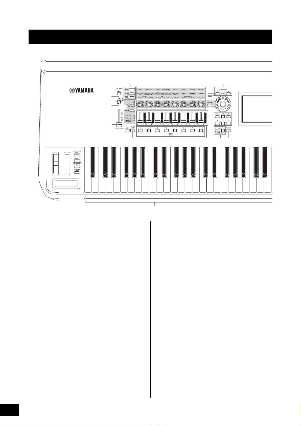
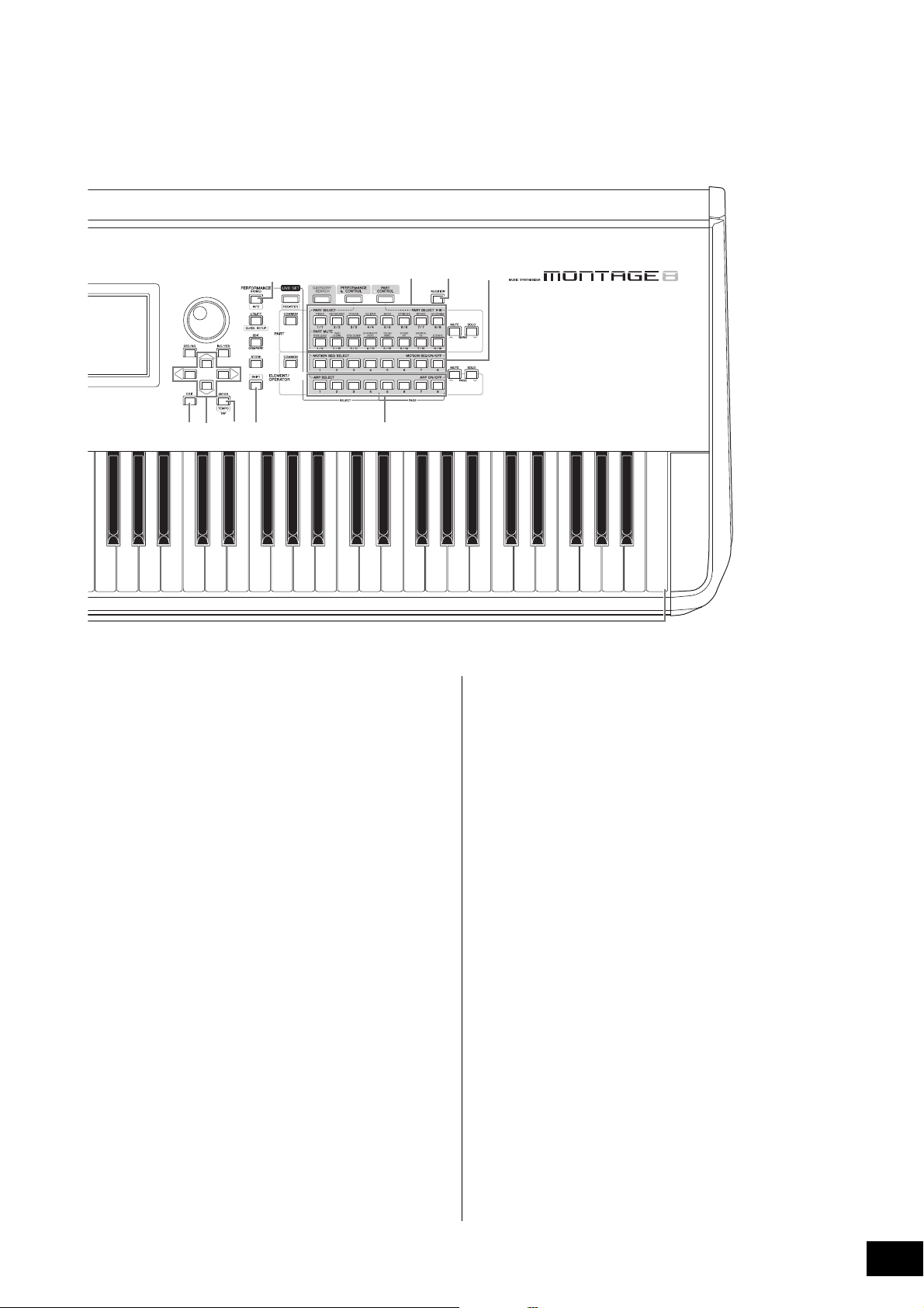
Top Panel
C1E0 F0 G0 A0 B0C0 D0A-1 B-1 C2
C3
1
23
4
7
6
C
B
%
8
9
)
D
^
!(
#$
A
@
*
&
5
E
Controls and Functions
1 Keyboard
The MONTAGE6 features a 61-key keyboard, while the
MONTAGE7 has 76 keys and the MONTAGE8 has 88 keys.
All are equipped with a touch response feature (both initial
touch and aftertouch). With initial touch, the instrument
senses how strongly or softly you play the keys, and uses
that playing strength to alter the sound in various ways,
depending on the selected Performance. Aftertouch, on the
other hand, lets you alter the sound by the amount of
pressure you apply to a note after playing it. In addition, any
of a variety of functions can be assigned to aftertouch for
each part.
2 Pitch Bend wheel
Controls the pitch bend effect. You can also assign other
functions to this controller.
3 Modulation wheel
Controls the modulation effect. You can also assign other
functions to this controller.
4 Ribbon Controller
This controller is touch sensitive, and is controlled by running
your finger lightly across its surface laterally. You can assign
various functions to this controller as desired.
5 [ASSIGN 1] and [ASSIGN 2] buttons
(Assignable switches 1 and 2)
You can call up the specific Element/Operator of the
selected Performance by pressing each of these buttons
during your keyboard performance. In addition, you can
assign other functions to these switches. When one of these
effects is turned on, the corresponding button will light up
and vice-versa.
6 [MOTION SEQ HOLD] (Motion Sequencer
hold) button
Pressing this button while the Motion Sequencer is playing,
results in the sound being held or frozen at the exact point in
the sequence when the button was pressed. When the hold
effect is turned on, the button lights.
7 [MOTION SEQ TRIGGER] (Motion Sequencer
trigger) button
When you press this button, the Motion Sequence starts
again from the beginning. The button lights fully when
pressed.
8 [MASTER VOLUME] slider (page 15)
Move the slider up or down to control the output level from
the OUTPUT (BALANCED) [L/MONO]/[R] jacks and the
[PHONES] jack.
MONTAGE Owner’s Manual
6
Page 17
Controls and Functions
C4 C5 C6 C7
H
G
J
KP
L
M
N
O
c
I
F
Q R S T
ad
b
e
f
gh
ij
The illustration shows the MONTAGE8, but the information applies to all models.
9 A/D INPUT [GAIN] knob (page 44)
Use this to adjust the input gain of the audio signals at the
A/D INPUT [L/MONO]/[R] jacks. Turning the knob clockwise
increases the gain level.
Detects the peak level and lights up the PEAK LED in red
when the level is just short of clipping. Adjust the knob so
that the corresponding PEAK LED only occasionally flashes
whenever the input signal reaches the maximum level.
NOTE
You may need to change the setting depending on the input level of
the external equipment connected to the A/D INPUT [L/MONO]/[R]
jacks, in the following order: [UTILITY] [Settings] [Audio I/O]
[A/D Input]. When the output level of the connected equipment (such
as a microphone, guitar or bass) is low, set this parameter to “Mic.”
When the output level of the connected equipment (such as a
synthesizer keyboard or CD player) is high, set this parameter to
“Line.”
) A/D INPUT [ON/OFF] button (page 44)
Switches whether or not this instrument accepts the audio
signal input via the A/D INPUT [L/MONO]/[R] jack. When A/D
Input is enabled, the button lights; when disabled, it turns off.
! Knob Function [TONE]/[EQ/FX]/[ARP/MS]
button
Use this button to select functions to be assigned to Knobs 1
– 8. The button next to the currently active parameters will
light.
You can apply functions to be controlled commonly for all
Parts by using the PART [COMMON] button, or to be
controlled for only the selected Part by using the Number A
[1] – [16] buttons. The selected button will light.
@ [MULTI] (Multi Part control) button
Use this button to select functions assigned to Knobs 1 – 8.
Pressing the button repeatedly switches in the following
order: PAN VARIATION REVERB. The lamp next to the
currently active parameters will light. All knobs correspond
to Parts 1 – 8 or 9 –16 (depending on the currently selected
Part).
# [ARP ON/OFF] (Arpeggio on/off) button
Press this button to enable or disable playback of the
Arpeggio. If the Arpeggio Switch of the selected Part is set to
off, however, pressing this button has no effect. When
Arpeggio is enabled, the button lights; when disabled, it
turns off.
$ [MOTION SEQ ON/OFF] (Motion Sequencer
on/off) button
Determines whether the Motion Sequencer is active or not. If
the Motion Sequencer switch of the selected Part or Lane is
set to off, however, pressing this button has no effect. When
the Motion Sequencer is active, the button lights.
MONTAGE Owner’s Manual
7
Page 18
Controls and Functions
% Knobs 1 – 8
These eight highly versatile knobs let you adjust various
important parameters, such as the current Part, Arpeggio
tempo, and the Motion Sequencer.
Pressing the knob function [TONE]/[EQ/FX]/[ARP/MS]
button, the Multi part control [MULTI] button, or the Assign
[ASSIGN] button in the upper left corner changes the
functions assigned to the knobs.
^ Control Sliders 1 – 8
These sliders control the volume balance of the sound, by
letting you adjust the individual levels of the 16 Parts (1 – 8 /
9 – 16), the eight Elements for Normal Parts (AWM2), the
eight FM Operators for a Normal Part (FM-X), and eight Keys
of the Drum Part, in different ways depending on the
conditions of the various buttons.
When PART
[COMMON]
button is on:
[PERFORMANCE
CONTROL]
[PART CONTROL] Levels of Parts 1 – 8 Levels of Parts 9 –
Levels of Parts 1 – 8 Levels of Elements/Keys/Operators 1 – 8 of a
When Number A
[1] – [8] buttons
are on:
selected Part
When Number A
[9] – [16]
buttons are on:
16
NOTE
• If all of the Control Sliders are set to the minimum, you may not
hear any sound from the instrument, even when playing the
keyboard or a Song. If this is the case, raise all the sliders to a
suitable level.
• The [MASTER VOLUME] slider controls the overall audio output
level of this instrument. On the other hand, the Control Sliders
control the level of each Element/Key/Operator of the Parts and the
volume for each Part of the Performance as a parameter.
Accordingly, the values set via the Control Sliders can be stored as
Performance data.
& SCENE [1] – [8] buttons
You can assign different “snapshots” of important Partrelated parameters such as track mute status and the basic
Mixing setup to the SCENE [1] – [8] buttons as Part Scenes.
When Scene-related parameters are edited and press any of
the SCENE [1] – [8] buttons while holding down the [SHIFT]
button, the edit is stored for the currently selected [SCENE]
button. The stored information is restored by pressing the
selected button. The currently selected button fully lights, the
button stored information lights dimly, and the button without
stored information is turned off.
NOTE
You can also control the Super Knob by using the foot controller
(FC7). For details, refer to page 28.
B SEQ TRANSPORT button
These buttons control recording and playback of the Song
sequence data.
[T] (Top) button
Instantly returns to the beginning of the current Song
(i.e., the first beat of the first measure).
[LL ] (Reverse) button
Press briefly to move back one measure at a time.
[RR ] (Forward) button
Press briefly to move forward one measure at a time.
[I] (Record) button
Press this to call up the Record setup display. (The
button flashes.) Press the [R] (Play) button to start
recording. (The [I] (Record) button lights.)
[J] (Stop) button
Press to stop recording or playback. This button can also
be used when you want to stop Arpeggio playback, even
when Arpeggio is set to continue playback even after the
note is released (Arpeggio hold switch is ON).
[R] (Play) button
Press to start playback or recording of a Song. During
recording and playback, the button flashes at the current
tempo.
C OCTAVE [-] and [+] buttons
Use these buttons to change the octave range of the
keyboard. These buttons also function as Transpose [-] and
[+] buttons. To lower or raise the pitch of the note in semitone
steps, hold down the [SHIFT] button and press the
corresponding [-]/[+] button. To restore the normal octave
setting, press both buttons simultaneously. The buttons light
or flash in different ways depending on the octave setting.
For details, see the Reference Manual PDF document.
D [CONTROL ASSIGN] button
While the parameter assignable to controllers is selected on
the display, press this button and operate the desired
controller for assignment. The controller setting display
appears.
* [ASSIGN] button
Switches the functions assigned to knobs as Assign 1 – 8.
By using the PART [COMMON] button and the Number A [1]
– [16] buttons, you can set whether the functions are
commonly effective for all Parts or only for one selected Part.
When the effect is turned on, the corresponding button
lights.
( KNOB POSITION [1] and [2] buttons
Stores the parameter values of Assign 1 – 8. You can
instantly switch between the two buttons.
A Super Knob
Simultaneously controls the parameters (Assign 1 – 8)
assigned to the eight knobs.
MONTAGE Owner’s Manual
8
E Touch panel LCD
The LCD indicates the parameters and values related to the
currently selected operation. You can operate by touching
the display.
F Data dial
For editing the currently selected parameter. To increase the
value, turn the dial right (clockwise); to decrease the value,
turn the dial left (counter-clockwise). If a parameter with a
wide value range is selected, you can change the value in
broader strokes by quickly turning the dial.
Page 19
Controls and Functions
G [INC/YES] button
For increasing the value of the currently selected parameter
(INC: increment). This button can also be used to execute a
Job or Store operation.
Simultaneously hold down the [SHIFT] button and press the
[INC/YES] button to quickly increase the parameter value in
10-step jumps.
H [DEC/NO] button
For decreasing the value of the currently selected parameter
(DEC: decrement). This button can also be used to cancel a
Job or Store operation.
Simultaneously hold down the [SHIFT] button and press the
[DEC/NO] button to quickly decrease the parameter value in
10-step jumps.
I Cursor buttons
The cursor buttons move the “cursor” around the display,
highlighting and selecting the various parameters.
J [EXIT] button
The menus and displays of the MONTAGE are organized
according to a hierarchical structure. Press this button to exit
from the current display and return to the previous level in
the hierarchy.
K [ENTER] button
Use this button to call up the display of the selected menu,
or to execute a Job or Store operation.
Simultaneously hold down the [SHIFT] button and press the
[ENTER] button to call up the Tempo setting display.
L [PERFORMANCE] button
Use this button to return to the Performance Play display.
The button fully lights when the Performance Play display is
shown. This button lights dimly when the Utility display is
shown.
Simultaneously hold down the [SHIFT] button and press the
[PERFORMANCE] button to call up the Overview display.
M [UTILITY] button
Use this button to call up the Utility display for making overall
system settings. The button fully lights when the Utility
display is shown and the button lights dimly when other
displays are shown.
Simultaneously hold down the [SHIFT] button and press the
[UTILITY] button to call up the Quick setup display.
N [EDIT] button
Use this button to call up the display for editing
Performances (page 18) and Live Sets (page 30). Also,
pressing this button while editing Performance parameters
lets you switch between the just-edited sound and its
original, unedited condition, allowing you to hear how your
edits affect the sound (Compare function). The button lights
when the edit display is shown and the button flashes while
Compare is active.
O [STORE] button
Use this button to call up the Store display. The button fully
lights when the Store display is shown and the button lights
dimly when other displays are shown.
P [SHIFT] button
Pressing this button along with another button enables you
to execute various commands. For details, refer to the “Shift
Function List” (page 55).
Q [LIVE SET] button
Use this button to store all your favorite, often-used
Performances in a single, easy-to-access location and call
them up.
Simultaneously hold down the [SHIFT] button and press the
[LIVE SET] button to call up the Live Set display for storing
the currently selected Performance to the Live Set. This is
one more useful way you can quickly switch among
Performances you need in live performance situations.
The button fully lights when the Live Set display is shown. If
the Live Set display is not shown, the button lights dimly
when the Live Set function is active and the button’s lamp is
off when the function is NOT active.
R [CATEGORY SEARCH] button
The Category Search function (page 20) can be accessed
by using this button.
Use this button while the Performance Play display is shown
to call up the Performance Category Search display for
selecting the entire Performance. When the cursor is on the
Part name in the Performance Play display, simultaneously
hold down the [SHIFT] button and press the [CATEGORY
SEARCH] button to call up the Part Category Search display,
allowing you to select a sound type for the currently selected
Part. The button fully lights when the Category Search
display is shown. If the Category Search display is not
shown, the button lights dimly when the Category Search
function is active and the button’s lamp is off when the
function is NOT active.
S [PERFORMANCE CONTROL] button
Use this button with the Number A [1] – [16] buttons, the
Number B [1] – [8] buttons, and the Number C [1] – [8]
buttons, the PART [MUTE] button, and the PART [SOLO]
button to control Performances. When this button is turned
on, the following functions can be operated. The button fully
lights when it is turned on and the button lights dimly when it
is turned off.
Number buttons PART [MUTE] button ONPART [SOLO] button
Number A [1] – [8] buttons
(upper line)
Number A [9] – [16] buttons
(lower line)
Number B [1] – [8] buttons Switch of Motion Sequence types (1 – 8)
Number C [1] – [8] buttons Switch of Arpeggio types (1 – 8)
Part select (1 – 8) Part solo (1 – 8)
Part mute (1 – 8) Part solo (1 – 8)
ON
T [PART CONTROL] button
Use this button with the Number A [1] – [16] buttons, the
Number B [1] – [8] buttons, and the Number C [1] – [8]
buttons, the PART [MUTE] button, and the PART [SOLO]
button to control Parts. When this button is turned on, the
following functions can be operated. The button fully lights
when it is turned on and the button lights dimly when it is
turned off.
MONTAGE Owner’s Manual
9
Page 20
Controls and Functions
Number buttons PART [MUTE]
Number A [1] – [8]
buttons (upper line)
Number A [9] – [16]
buttons (lower line)
Number B [1] – [8]
buttons
Number C [1] – [8]
buttons
button and PART
[SOLO] are OFF
Part select (1 – 8) Part mute (1 – 8) Part select (1 – 8)
Part select (9 – 16) Part mute (9 – 16) Part solo (9 – 16)
Motion Sequencer for each Part ON/OFF (1 – 8 / 9 – 16)
Arpeggio for each Part ON/OFF (1 – 8 / 9 – 16)
PART [MUTE]
button ON
PART [SOLO]
button ON
a [AUDITION] button
Use this button (in the Performance Play, Live Set, or
Category Search displays) to play back or stop a sample
phrase showcasing the selected Performance sound. This
sample phrase of the Performance is called the “Audition
phrase.” The button fully lights when it is ON and the button
lights dimly when the Audition function is active such as in
the Category Search display.
b PART [COMMON] button
Turning on this button lets you edit the parameters
commonly applied to all Parts. The button fully lights when it
is turned on and the button lights dimly when it is turned off.
(Only in the case of selecting pages in the Live Set display,
this button can be used even if the lamp is off.)
f Number C [1] – [8] buttons
Use these buttons to select Arpeggio types on the
Performance Play display and to turn the Arpeggio for each
Part ON/OFF.
The buttons can be used to mute Elements/Keys/Operators
from the Edit display. The buttons can also be used to select
Performances from the Category Search display. In the Live
Set display, the Number C [1] – [4] buttons can be used to
select Performances in the fourth line, and the Number C [5]
– [8] buttons can be used to select Live Set pages 13 – 16.
According to each of the displays, the button fully lights
when it is selected, the button lights dimly when it is
selectable, and the button lamp is off when not selectable.
(Only in the case of selecting pages in the Live Set display,
this button can be used even if the lamp is off.)
g PART [MUTE ] bu tton
By turning this button on, the Number A [1] – [16] buttons
can be used as mute on/off controls. The button fully lights
when it is turned on and the button lights dimly when it is
turned off. The button can also be used to switch Live Set
banks from the Live Set display.
c ELEMENT/OPERATOR [COMMON] button
Turning this button on lets you edit the parameters
commonly applied to all Elements/Keys/Operators. The
button fully lights when it is turned on and the button lights
dimly when it is turned off.
d Number A [1] – [16] buttons
Use these buttons to select Parts on the Performance Play
display and the Edit display.
The buttons can also be used to select a main category from
the Category Search display. In the Live Set display, the
Number A [1] – [4] buttons can be used to select
Performances in the first line, and the Number A [9] – [12]
buttons can be used to select Performances in the second
line. The Number A [5] – [8] buttons can be used to select
Live Set pages 1 – 4, and the Number A [13] – [16] buttons
can be used to select Live Set pages 5 – 8.
According to each of the displays, the button fully lights
when it is selected, the button lights dimly when it is
selectable, and the button lamp is off when not selectable.
(Only in the case of selecting pages in the Live Set display,
this button can be used even if the lamp is off.)
e Number B [1] – [8] buttons
Use these buttons to select Motion Sequencer types on the
Performance Play display and to turn the Motion Sequencer
for each Part ON/OFF.
The buttons can be used to select Elements/Keys/Operators
from the Edit display. The buttons can also be used to select
sub categories from the Category Search display. In the Live
Set display, the Number B [1] – [4] buttons can be used to
select Performances in the third line, and the Number B [5] –
[8] buttons can be used to select Live Set pages 9 – 12.
According to each of the displays, the button fully lights
when it is selected, the button lights dimly when it is
selectable, and the button lamp is off when not selectable.
h PART [SOLO] button
By turning this button on, the Number A [1] – [16] buttons
can be used as solo on/off controls for Parts. The button fully
lights when it is turned on and the button lights dimly when it
is turned off. The button can also be used to switch Live Set
banks from the Live Set display.
i ELEMENT/OPERATOR [MUTE] button
By turning this button on, the Number B [1] – [8] buttons can
be used to select Elements/Keys/Operators 1 – 8, and the
Number C [1] – [8] buttons can be used as mute on/off
controls for Elements/Keys/Operators 1 – 8. The button lights
dimly when it works as mute on, and fully lights when it works
as mute off. For operations other than Part editing, the button
is off. The button can also be used to switch Live Set banks
from the Live Set display.
j ELEMENT/OPERATOR [SOLO] button
By turning this button on, the Number B [1] – [8] buttons (or
the Number C [1] – [8] buttons) can be used to as solo on/off
controls for Elements 1 – 8. The button fully lights when solo
is on, and lights dimly when solo is off. In other situations,
except for Part editing operations, the button is off. The
button can also be used to switch Live Set banks from the
Live Set display.
Number buttons ELEMENT/OPERATOR
[MUTE] button ON
Number B [1] – [8] buttons Element select (1 – 8) Element solo (1 – 8)
Number C [1] – [8] buttons Element mute (1 – 8) Element solo (1 – 8)
ELEMENT/OPERATOR
[SOLO] button ON
MONTAGE Owner’s Manual
10
Page 21
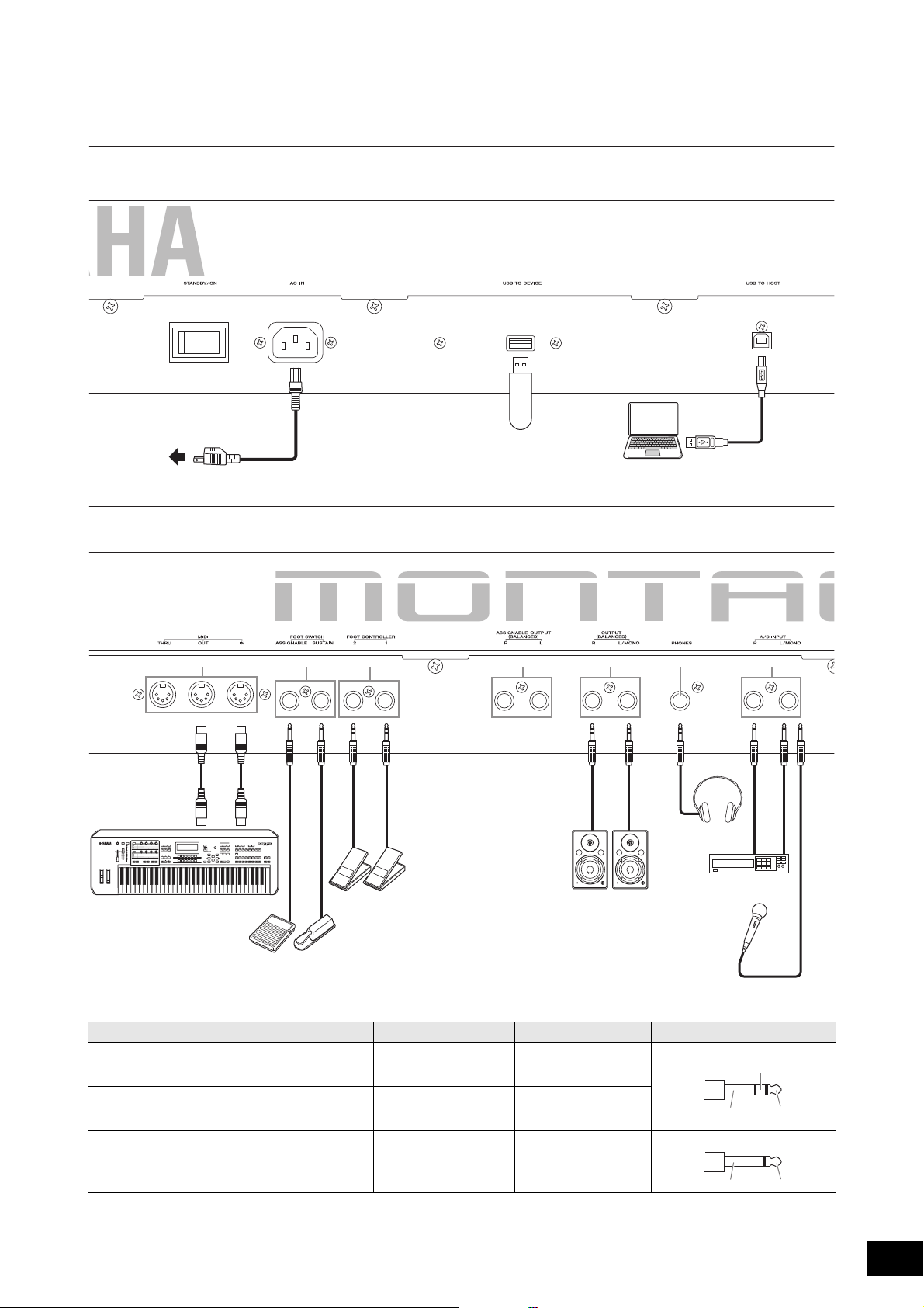
Rear Panel
FC3,
FC4,
FC5
FC4,
FC5
FC7
12 3 4
5 6 7 8 9 ) !
Left side of Rear Panel
Right side of Rear Panel
The illustration shows the MONTAGE8, but the information applies to all models.
USB flash memory device
Computer
External MIDI keyboard
Powered speaker
Headphones
Playback equipment
Microphone
AC outlet
Ring
Sleeve Tip
Sleeve Tip
Controls and Functions
Jack List (Pin Alignment)
8 ASSIGNABLE OUTPUT (BALANCED) [L], [R]*
9 OUTPUT (BALANCED) [L/MONO], [R]*
) [PHONES] Tip: L
! A/D INPUT [L/MONO], [R] Tip: Signal
* These jacks are also compatible with TS phone plugs; when used, the connection is unbalanced.
Input and Output Jacks Polarities Balanced/Unbalanced Configurations
Tip: Hot (+)
Ring: Cold (-)
Sleeve: Ground
Ring: R
Sleeve: Ground
Sleeve: Ground
Balanced TRS phone plug
—
Unbalanced TS phone plug
MONTAGE Owner’s Manual
11
Page 22

Controls and Functions
Left side of Rear Panel
1 [STANDBY/ON] switch
Press to set the power to On or Standby.
2 [AC IN] (AC Power Cord Socket)
Plug the AC power cord supplied with this instrument.
3 [USB TO DEVICE] terminal
Used to connect this instrument to a USB flash memory
device. This lets you save data created on this instrument to
an external USB flash memory device and load data from a
USB flash memory device to the instrument. Save/Load
operations can be performed: [UTILITY] [Contents]
[Store/Save] or [Load].
NOTE
• Only USB flash memory devices can be recognized by this
instrument. No other USB devices (such as a hard disk drive, CDROM drive and USB hub) can be used.
• The instrument supports the USB 1.1 to 3.0 standard. However,
note that the transfer speed differs depending on the data type
and the condition of this instrument.
4 [USB TO HOST] terminal
Used to connect this instrument to a computer via a USB
cable, and allows you to transfer MIDI data and audio data
between the devices. Unlike MIDI, USB can handle multiple
ports via a single cable (page 50). For information about
how the MONTAGE handles Ports, see page 50.
NOTE
Audio data sending capability for the instrument is a maximum
32 channels (16 stereo channels) at a sampling frequency of
44.1 KHz; or maximum 8 channels (4 stereo channels) for a
sampling frequency of 44.1 KHz to 192 KHz. Audio data receiving
capability is a maximum 6 channels (3 stereo channels).
Right side of Rear Panel
NOTE
• The term “FC3” in this Owner’s Manual refers collectively to the
FC3 and other footswitches compatible with the FC3, such as the
FC3A.
• The term “FC4” in this Owner’s Manual refers collectively to the
FC4 and other footswitches compatible with the FC4 such as the
FC4A.
7 FOOT CONTROLLER [1]/[2] jacks
For connection of an optional foot controller (FC7, etc.). This
jack lets you continuously control one of various different
assignable functions for Part edit—such as volume, tone,
pitch, or other aspects of the sound (see the Reference
Manual PDF document).
8 ASSIGNABLE OUTPUT (BALANCED) [L] and
[R] jacks (TRS balanced output)
Line level audio signals are output from this instrument via
these TRS balanced outputs. These outputs are
independent of the main output (at the OUTPUT [L/MONO]/
[R] jacks below), and can be freely assigned to any of the
Drum Part keys or the Parts. This lets you route specific Parts
or sounds for processing with a favorite external effect unit.
The Parts which can be assigned to these jacks are as
follows:
• Drum Part key to which the drum/percussion instrument is
assigned
• Metronome (Click)
• Any Part of a Performance*
* Includes Audio Input Part
For details, see the Reference Manual PDF document.
9 OUTPUT (BALANCED) [L/MONO] and [R]
jacks (TRS balanced output)
Line level audio signals are output via these TRS balanced
outputs. For monophonic output, use only the [L/MONO]
jack.
5 MIDI [IN], [OUT], [THRU] terminal
MIDI [IN] is for receiving control or performance data from
another MIDI device, such as an external sequencer, letting
you control this instrument from the connected separate
MIDI device.
MIDI [OUT] is for transmitting all control, performance and
playback data from this instrument to another MIDI device,
such as an external sequencer.
MIDI [THRU] is simply for redirecting any received MIDI data
(via MIDI [IN]) to connected devices, allowing convenient
chaining of additional MIDI instruments.
6 FOOT SWITCH [ASSIGNABLE]/[SUSTAIN]
jacks
For connection of an optional FC3/FC4/FC5 Footswitch to the
[SUSTAIN] jack and a FC4/FC5 Footswitch to the
[ASSIGNABLE] jack. When connected to the [SUSTAIN]
jack, the Footswitch controls sustain. When connected to
[ASSIGNABLE], it can control one of various assignable
functions.
) [PHONES] (Headphone) jack
This standard stereo phones jack is for connection to a set of
stereo headphones. This jack outputs audio signals identical
to those from the OUTPUT [L/MONO] and [R] jacks.
! A/D INPUT [L/MONO]/[R] jacks
External audio signals can be input via these phone jacks
(1/4" mono phone plug). Various devices such as a
microphone, CD player or synthesizer can be connected to
these jacks and their audio input signal can be sounded as
the Audio Part.
In addition, you can use the special Vocoder feature by
connecting a microphone to this [L/MONO] jack and
inputting your Voice to the microphone.
You can also use the Envelope Follower and ABS (Audio
Beat Sync) features. Envelope Follower is a function for
detecting the volume envelope of the input signal waveform
and modifying sounds dynamically.
MONTAGE Owner’s Manual
12
Page 23

NOTE
• A guitar or bass having active pickups can be directly connected.
However, when using passive pickups, connect the instrument via
an effect device.
• The Vocoder/Envelope Follower can be controlled from all Part
outputs, and not just the A/D INPUT [L/MONO]/[R] jack.
ABS (Audio Beat Sync) is a function for detecting the beat of
the audio signal input from these jacks and synchronizing
the beat with the Motion Sequencer or Arpeggio.
Use 1/4" mono phone plugs. For stereo signals (such as from
audio equipment), use the [L/MONO]/[R] jacks. For mono
signals (such as from a microphone or guitar), use only the
[L/MONO] jack.
For details about the Envelope Follower and ABS features,
see the Reference Manual PDF document.
Controls and Functions
MONTAGE Owner’s Manual
13
Page 24
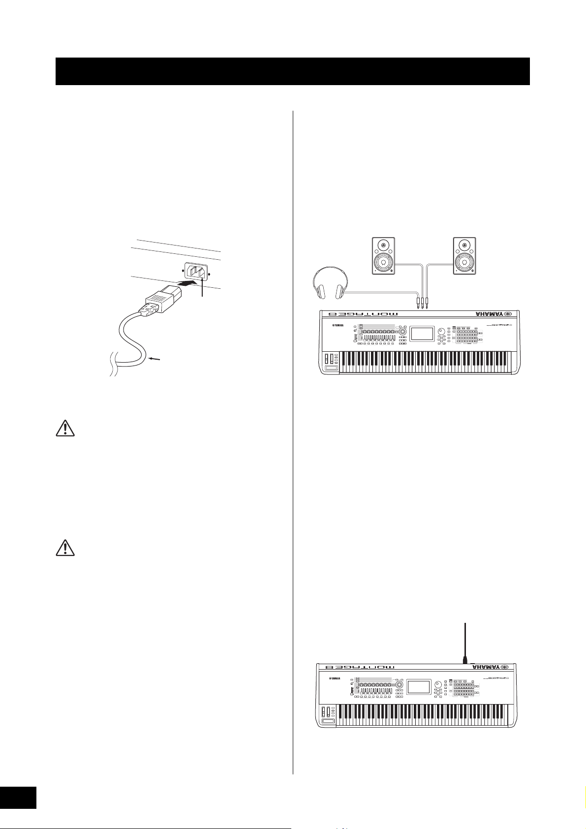
WARNING
CAUTION
Setting Up
Rear panel
AC IN
Power cord (included)
Powered speaker
(left)
Powered speaker
(right)
Headphones
OUTPUT L/MONO OUTPUT R
PHONES
AC IN
[STANDBY/ON]
switch
Power Supply
Connect the supplied AC power cord in the following order.
Make sure the [STANDBY/ON] switch on the instrument is set
to the Standby position.
1 Connect the supplied power cord to the AC IN
on the instrument’s rear panel.
2 Connect the other end of the power cord to
an AC outlet.
NOTE
Follow this procedure in reverse order when disconnecting the power
cord.
• Use only the AC power cord supplied with your instrument.
The use of an inappropriate replacement can lead to
overheating or electric shock.
• The power cord supplied with your instrument must not be
used with other electrical equipment. Failure to observe this
precaution can result in the equipment being damaged or
cause a fire.
• Make sure your instrument the voltage requirement for the
country or region in which it is being used.
The instrument remains charged and draws a small amount of
power even when the [STANDBY/ON] switch is set to the Standby
position. If you intend not to use it for an extended period of
time, therefore, make sure to unplug the power cord from the
wall outlet.
Connecting Speakers or Headphones
Since the instrument has no built-in speakers, you will need
to monitor the sound of the instrument by using external
equipment. Connect a set of headphones, powered
speakers, or other playback equipment as illustrated below.
When making connections, be sure that your cables have
the appropriate ratings.
Powering Up the System
Make sure the volume settings of the instrument and external
devices such as powered speakers are turned to the
minimum before turning the power on. When connecting the
instrument to powered speakers, turn on the power switch of
each device in the following order.
When turning the power on:
First, the instrument (the display will turn on and the buttons
will light), then the connected powered speakers.
When turning the power off:
First, the connected powered speakers, then the instrument
(the display will turn off and the buttons will turn off).
Keep in mind that the [STANDBY/ON] switch is located at the
right side (from the view of the keyboard) of the AC IN socket
on the rear panel of the instrument.
14
MONTAGE Owner’s Manual
Page 25
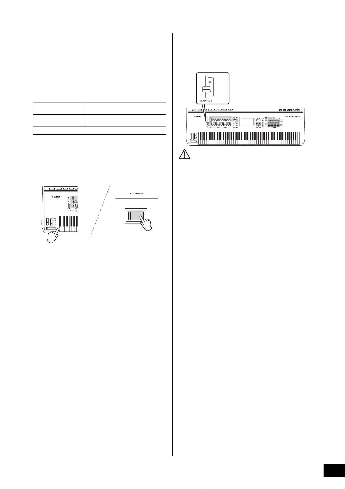
Setting Up
CAUTION
Max.
Min.
Auto Power Off function
To prevent unnecessary power consumption, this instrument
features an Auto Power Off function that automatically turns
the power off if the instrument is not operated for a specified
period of time.
Auto Power Off Setting
The amount of time that elapses before the power is
automatically turned off can be set.
Instructions:
Setting Value (min.):
Default Setting (min.):
Disabling Auto Power Off (simple method)
Turn the power on while holding down the lowest key on the
keyboard. An “Auto power off disabled” message appears
briefly and Auto Power Off is disabled. The setting is
retained even if the power is turned off.
[UTILITY] [Settings] [System] [Auto
Power Off]
off (disables Auto Power Off), 5, 10, 15, 30,
60, 120
30
Adjusting the Master Volume output
Adjust the overall level of this instrument by using the
[MASTER VOLUME] slider.
Do not listen with the headphones at high volume for long
periods of time. Doing so may cause hearing loss.
Restoring the initial factory settings (Initialize All Data)
NOTICE
• Even when the power is turned off, electricity is still flowing to
the instrument at the minimum level. To shut off the electricity
completely, make sure you unplug the power cord from the
wall AC outlet.
• Depending on the instrument status, the power may not turn
off automatically, even after the elapse of the specified period
of time. Always turn off the power manually when the
instrument is not in use.
• When the instrument is not operated for a specified period of
time while connected to an external device such as an
amplifier, speaker or computer, make sure to follow the
instructions in the Owner’s Manual to turn off the power to the
instrument and the connected devices in the proper sequence,
in order to protect the devices from damage. If you do not
want the power to turn off automatically when a device is
connected, disable Auto Power Off.
• The setting will revert to its default value if not backed up
before the power is turned off.
• When Auto Power Off is set to “off,” the value will be retained
even if the backup data saved on another device is loaded to
the instrument. When Auto Power Off is set to something other
than “off,” the value will be overwritten with loaded data.
NOTICE
When the Initialize All Data operation is executed, all the
Performance, Song, and any system settings you created on the
Utility display will be erased. Make sure you are not overwriting
any important data. Be sure to save all important data to your
USB flash memory device before executing this procedure
(page 53).
1 Press the [UTILITY] button or touch the
UTILITY icon in the upper right of the screen
to call up the Utility display.
2 Touch the [Settings] tab in the left of the
screen and then touch the [System] tab.
The entire system setting display appears.
3 Touch [Initialize All Data] in the lower right of
the screen.
The display prompts you for confirmation. To cancel this
operation, touch the [Cancel No] in the screen or press
the [DEC/NO] button on the panel.
4 Touch [Yes] in the screen or press the [INC/
YES] button to execute the Initialize All Data
operation.
NOTE
• The setting time is approximate.
• To turn the power on after Auto Power Off has been executed,
• When the factory settings are restored, the setting time is changed
press the [STANDBY/ON] switch.
to the default value (30 min.).
MONTAGE Owner’s Manual
15
Page 26
Basic Operation and Displays
1 2 76543
Navigation bar
9
8
The MONTAGE features a convenient touch panel display. You can operate various settings and select desired parameters by
directly touching the screen. Furthermore, you can use the data dial and other buttons for display operations.
Display (touch panel) configuration
This section explains the navigation bar and the display
selecting tabs which are common to all types of displays. For
the purpose of illustration, the Live Set display which
appears when the MONTAGE is turned on and the
Performance Play display (Home) are used as examples.
NOTE
You can change the start-up display (the display that first appears
when the power is turned on). For details about the setting, see
page 45.
Live Set display
Touch the desired icon to call up the corresponding
quick setup display.
6 TEMPO SETTING icon
Displays the tempo of the currently selected
Performance. Touch the icon to call up the Tempo setting
display.
7 UTILITY icon
Touch the icon to call up the last opened display among
the Utility displays.
Performance Play display
1 HOME icon
Moves to the Performance Play display.
2 EXIT icon
Functions same as the [EXIT] button on the panel. Press
this icon to exit from the current display and return to the
previous level in the hierarchy.
3 INFORMATION area
Displays helpful information, including the currently
selected display name.
4 EFFECT icon
Touch the icon to call up the Effect switch display. The
icon turns off when any of the Effect blocks (Insertion,
System or Master) is off.
5 QUICK SETUP icon
Displays the settings of Local Control ON/OFF and MIDI
IN/OUT.
The keyboard-shaped icon lights up when Local Control
is set to ON and turns off when Local Control is set to
OFF.
When MIDI is set as the MIDI IN/OUT setting, a MIDI
connector-shaped icon appears. When USB is set as the
MIDI IN/OUT setting, a USB connector-shaped icon
appears.
8 LIVE SET icon
Touch the icon to call up the Live Set display.
9 Display selecting tabs
Touch the desired tab to call up the corresponding
display.
Moving the cursor
Use these four buttons to navigate the display, moving the
cursor around the various selectable items and parameters
in the screen. When selected, the relevant item is highlighted
(the cursor appears as a dark block with inverse characters).
You can change the value of the item (parameter) at which
the cursor is located by using the data dial, [INC/YES] and
[DEC/NO] buttons.
MONTAGE Owner’s Manual
16
Page 27

Basic Operation and Displays
Increases numberDecreases number
Increases number
Decreases number
3
4
21
5 6
7
8
1
2
43
5
6
Changing (editing) parameter values
Rotating the Data dial to the right (clockwise) increases the
value, while rotating it to the left (counter-clockwise)
decreases it.
Pressing the [INC/YES] button increases a parameter value
by one step, and pressing [DEC/NO] button decreases it.
For parameters with large value ranges, you can increase
the value by 10 by simultaneously holding down the [SHIFT]
button and pressing the [INC/YES] button. To decrease by
10, simultaneously hold down the [SHIFT] button and press
the [DEC/NO] button.
Naming (inputting characters)
You can freely name the data you’ve created, such as
Performances, Songs, and files saved to a USB storage
device. Touch the Naming parameter or move the cursor to
the Naming parameter and press the [ENTER] button to call
up the input character display.
Inputting using the keys on the
keyboard and numeric keypad display
For some parameters, you can also enter the value directly,
using the LCD display as a numeric keypad or using keys on
the keyboard. Input via the keys can be activated when
inputting parameters relating to note and velocity. Input via
the numeric keypad display can be activated when inputting
velocity-related parameters. Touch the desired parameter or
move the cursor to the parameter and press the [ENTER]
button to call up the display having the two input tabs
(shown below).
1 Enables keyboard input.
You can play any note on the keyboard and the note or
velocity are input.
2 Enables numeric keypad input.
You can input a number directly by using the numeric
keypad. You can also use the data dial, the [INC/YES]
button, and the [DEC/NO] button to increase and
decrease the input number.
1 Deletes all characters.
2 Reverts to the default name.
3 Switches between uppercase and lowercase
alphabetical characters.
4 Calls up the display for entering numbers, punctuation
marks and miscellaneous characters.
5 Inserts a space (blank) at the cursor position. (You can
also use the [INC/YES] button for the same operation.)
6 Moves the cursor position.
7 Deletes the previous character (backspace). (You can
also use the [DEC/NO] button for the same operation.)
8 Completes the text input and closes the display.
Numeric keypad display
3 Erases all numbers.
4 Restores the value to the last setting.
5 Deletes the last digit of the number.
6 Completes the input operation and closes the numeric
keypad display.
MONTAGE Owner’s Manual
17
Page 28

Quick Guide — Selecting Performances
Multiple
Performances
One Performance
Part 1 (Piano)
Part 2 (Guitar)
Part 3 (Bass)
Par t 4 (Dr um )
The MONTAGE has 16 Parts and basic musical instrument
sounds are assigned to each Part. A single set of these
sounds is called a “Performance.” You can change sounds
as desired by selecting the appropriate Performance.
There are three Part types as follows.
Normal Parts (AWM2)
Normal Parts (AWM2) are mainly pitched musical instrument
type sounds (piano, organ, guitar, synthesizer, etc.) that can
be played over the full range of the keyboard.
This instrument features Banks for memorizing
Performances. There are basically four different types of
Banks: Preset, User, Library, and GM. The contained
Performances and features depend on the Bank as
described below.
Preset Banks
The Preset Banks contain a full set of specially programmed
Performances. Performances you’ve edited yourself cannot
be saved in the Preset Banks.
User Banks
The User Banks contain the Performances you have edited
and stored. The User Banks are initially empty.
NOTICE
If a Performance in a User Bank (User Performance) is
overwritten or replaced, that User Performance will be lost. When
you store an edited Performance, be careful not to overwrite any
important User Performances.
Library Banks
The Library Banks contain the Performances you have
added as Libraries. The Library Banks are initially empty.
(A Library can be added by importing a library file.)
GM Bank
The GM Bank contains the Parts allocated according to the
GM standard.
Normal Parts (FM-X)
Normal Parts (FM-X) are powerful FM Synthesis system
sounds. This sound is played conventionally from the
keyboard, with standard pitches sounding for each key.
Drum Parts
Drum Parts are mainly percussion/drum sounds that are
assigned to individual notes.
Performances can also be divided into two groups as
follows.
Single Part Performances
A Single Part Performance contains only one Part. Select this
if you want to play a single instrument.
Multi Part Performances
A Multi Part Performance contains multiple Parts. Select this
if you want to play sounds of multiple instruments by using
layering and splitting functions.
GM
GM (General MIDI) is a worldwide standard for Voice
organization and MIDI functions of synthesizers and tone
generators. It was designed primarily to ensure that any
song data created with a specific GM device would sound
virtually the same on any other GM device—no matter the
manufacturer or the model. The GM bank on this
synthesizer is designed to appropriately play back GM
song data. However, keep in mind that the sound may not
be exactly the same as played by the original tone
generator.
Each of these Banks include Performances organized
according to the Performance type.
NOTE
• For details about Performances, refer to “Basic Structure” in the
Reference Manual PDF document.
• For lists of the Performances, refer to the separate Data List PDF.
MONTAGE Owner’s Manual
18
Page 29

Quick Guide — Selecting Performances
1
2
5 6
3
4
Performance name
When you turn on your instrument for the first time, a Live Set
of the Preset Banks will be displayed in the top display. The
Live Set is a list in which Performances can be freely
arranged. Up to 16 Performances can be arranged over a
single page. You can play various Performances selected
from the Preset Live Sets.
Selecting a Performance from the Live Set
1 Press the [LIVE SET] button.
This calls up the Live Set display.
2 Touch the desired Performance on the
screen.
NOTE
• You can select a Performance by pressing the Number A [1] –
[4] and [9] – [12] buttons, the Number B [1] – [4] buttons, or
the Number C [1] – [4] buttons.
• To arrange the order of the Performances registered in the
Live Set, see page 30.
3 Play the keyboard.
Switching Performances
1 Press the [PERFORMANCE] button.
The Performance Play display appears, and the current
Performance name is shown.
1 Page (Switched by pressing [u] [d] in the screen,
the ELEMENT/OPERATOR [MUTE] button, or the
[SOLO] button. Selected by pressing the Number A
[5] – [8]/[13] – [16] buttons, the Number B [5] – [8]
buttons, or the Number C [5] – [8] buttons.)
2 Preset Bank/User Bank (switched by pressing the
[u] [d] in the screen, the PART [MUTE] button, or
the [SOLO] button)
3 Performance list
4 Active Performance names
5 Slot name
6 Flag (see chart below)
Flag Definition
AWM2 Performance comprised only of AWM2 Parts
FM-X Performance comprised only of FM-X Parts
FM-X+AWM2 Performance comprised of both AWM2 and FM-
MC Performance featuring Motion Control
SSS Performance featuring Seamless Sound
NOTE
“Seamless Sound Switching” is a feature that lets you switch
Performances smoothly without any notes being cut off. The SSS
feature is available for all Preset Bank Performances in this
instrument. However, SSS is available only for the Performance
containing Parts 1 – 8, not for the Performance with using Parts 9
– 16.
X Parts
Switching
2 Move the cursor to the Performance name
and select the desired Performance by using
the data dial, the [INC/YES] button, or the
[DEC/NO] button.
NOTE
• To quickly move forward through the Performance numbers in
10-step jumps, simultaneously hold down the [SHIFT] button
and press the [INC/YES] button.
• To decrease by 10, do the opposite; simultaneously hold
down the [SHIFT] button and press the [DEC/NO] button.
3 Play the keyboard.
MONTAGE Owner’s Manual
19
Page 30

Quick Guide — Selecting Performances
6
4
5
1 2 3
7 8
Using the Category Search function
The Performances are conveniently divided into specific
Categories, irrespective of their bank locations. The
categories are divided based on the general instrument type
or sound characteristics. The Category Search function
gives you quick access to the sounds you want.
1 Press the [CATEGORY SEARCH] button while
the Performance Play display is shown.
This calls up the Category Search display.
NOTE
You can open the Category Search display by selecting [Search]
from the menu that is called up when the Performance name is
touched.
1 Bank
2 Attribute
NOTE
Attributes are Performance properties and sorted according
to tone generator types or parts of Performances.
3 Keyword search
4 Main categories
5 Sub categories
6 Performance list of the selected category
NOTE
The selected Performance is displayed in white,
Performances with a single part are in green, and
Performances with multi parts are in blue.
7 For changing the sorting order
8 For changing the Performance list page
3 Touch and select the desired sub category
(
5).
This calls up the Performance lists of the selected
category (6).
NOTE
You can also select the desired sub category by using the
Number B [1] – [8] buttons.
4 Touch the desired Performance.
NOTE
You can also select the desired Performance by using the
Number C [1] – [8] buttons.
5 Touch the HOME icon or EXIT icon to actually
call up the selected Performance.
This closes the Category Search display.
NOTE
You can also use the [ENTER] button, the [EXIT] button, or the
[PERFORMANCE] button to finalize the selection.
Below is a list of the Categories and their panel
abbreviations.
Abbreviation Category
Piano Piano
Keyboard Keyboard instruments (Harpsichord, Clav,
Organ Organ
Guitar Guitar
Bass Bass
Strings Strings
Brass Brass
Woodwind Woodwind instruments
Syn Lead Synth Lead
Pad/Choir Synth Pad
Syn Comp Synth Comp
Chromatic Perc Chromatic Percussion (Marimba,
Drum/Perc Drum/Percussion
Sound FX Sound Effect
Musical FX Musical Effect
Ethnic Ethnic
No Assign No Assign
Init Initialize
etc.)
Glockenspiel, etc.)
6 Play the keyboard.
2 Touch and select the desired main category
(
NOTE
• You can filter the Performance lists by touching [Bank] (1)
• You can also filter the Performance lists by touching [Attribute]
• You can also select the desired main category by using the
MONTAGE Owner’s Manual
20
4).
and selecting the desired bank type from the list.
(2) and selecting the desired attribute type from the list.
Number A [1] – [16] buttons.
Page 31

Quick Guide — Selecting Performances
[Audition]
Selecting an Initialized Performance
Follow the steps below to select an Initialized Performance.
1 Touch [Init] of the main category in the
Category Search display.
2 Only initialized Performances are
displayed in the Performance list.
The Initialized Performances are divided into three
categories: [Initialized Perform] for the normal Parts
(AWM2), [Initialized FM] for the normal Parts (FMX), and [Initialized Drum] for the Drum Parts.
3 Select the desired Performance.
Selecting only Single Part Performances
You can filter out the Single Part Performances by using
the Attribute function.
Playback Audition phrase
You can hear a sample of Performance sounds. The sample
sound is referred to as “Audition phrase.”
1 Touch [Audition] in the Category Search
display.
The sample of the currently selected Performance plays.
If you select a different Performance during Audition
phrase playback, the audition phrase switches to that of
the newly selected Performance.
2 Touch [Audition] again to stop playback.
NOTE
• You can also playback/stop the Audition phrase by pressing
the [AUDITION] button on the front panel.
• You can playback/stop the Audition phrase by pressing the
[AUDITION] button on the front panel while the Performance
display or the Live Set display is shown.
1 Touch [Attribute] in the Category Search
display.
2 Touch [Single] from the menu in the left
of the screen.
3 Only Single Part Performances are
displayed in the Performance list, letting
you select the desired one.
MONTAGE Owner’s Manual
21
Page 32

Quick Guide — Playing the Keyboard
3
2
4
7
You can mix several different parts together in a layer, or split them across the keyboard, or even set up a combination layer/
split. Each Performance can contain up to eight different Parts. Press the [PERFORMANCE] button before playing the keyboard.
Performance Play display
In this condition, playing the keyboard sounds the Performance indicated in the display. The parameters shown in the
Performance Play display are briefly explained below. You can operate the icons by touching on the display.
1
56
8
9
)
!@
1 Performance name
2 Flag
3 Functions assigned to knobs
4 Part names
5 Switching Motion Sequencer on/off for Parts
6 Switching Arpeggio on/off for Parts
7 Note Limit for Parts
8 Switching Keyboard Control on/off for Parts
9 Switching Mute on/off for Parts
) Switching Solo on/off for Parts
! Volume of Parts 1 – 8
@ Meter (Audio Output Level)
MONTAGE Owner’s Manual
22
Page 33

Quick Guide — Playing the Keyboard
3
1
24
Switching a Part on/off
You can turn the eight Parts of the current Performance on or
off as desired.
Turning specific Parts on/off (Mute
function)
You can turn individual Parts on/off by using the Mute
function.
1
2
1 Press the [PERFORMANCE CONTROL]
button.
The button lamp lights, indicating that each Part can be
turned on/off.
2 Press any of the Number A [9] – [16] buttons.
The corresponding buttons [1] – [8] of the
pressed button will light dimly and the Part
will be muted.
Press the same button again to turn the button on and
disengage the mute function for that Part. You can turn
multiple Parts on/off by pressing their buttons.
4 Press any of the dimly lit Number A [1] – [16]
buttons. The pressed button will fully light
again and the Mute function for that Part will
be disengaged.
Soloing a specific Part
The Solo function is the opposite of Mute, and lets you
instantly solo a specific Part and mute all others.
1
3
1 Press the [PERFORMANCE CONTROL]
button.
2 Press the [SOLO] button.
The [SOLO] button lights, indicating that Solo is enabled.
3 Press any of the Number A [1] – [8] / [9] – [16]
buttons.
The pressed button will light and only the corresponding
Part among the Parts 1 – 8 will be sounded. (The
Number A [1] – [8] and [9] – [16] buttons work in
conjunction with each other.)
2
You can also mute parts by using the [PART CONTROL]
button with the operation below.
1 Press the [PART CONTROL] button.
2 Press the [MUTE] button to turn the button
on.
Among the Number A [1] – [16] buttons, only the buttons
whose corresponding Parts have sounds assigned to
them will light.
1
3, 4
2
3 Press the desired Number A [1] – [16] button
to mute the corresponding Part. The pressed
button will change from fully lit to dimly lit.
You can turn multiple Parts on/off by pressing multiple
buttons.
You can also solo a part by using the [PART CONTROL]
button with the operation below.
1 Press the [PART CONTROL] button.
2 Press the [SOLO] button to turn the button on.
Among the Number A [1] – [16] buttons, only the buttons
whose corresponding Parts have sounds assigned to
them will light dimly.
3 Press any of the Number A [1] – [16] buttons
to solo the corresponding Part. The pressed
button will change from being dimly lit to fully
lit.
You can change the solo Part by pressing any other
Number button.
4 Press the [MUTE] button to disengage the
Solo function.
MONTAGE Owner’s Manual
23
Page 34

Quick Guide — Playing the Keyboard
2
1
Using the Arpeggio function
This function lets you trigger rhythm patterns, riffs and
phrases using the current Part by simply playing notes on
the keyboard.
It not only provides inspiration and full rhythmic passages in
your live performances, but it gives you fully formed
instrumental backing parts of various music genres for ease
in creating songs.
You can assign the desired eight Arpeggio Types to each
Part and play back the Arpeggios of up to eight Parts
simultaneously.
You can also set the Arpeggio playback method, Note
range, Velocity range and Play Effects to create your own
original grooves.
NOTE
For details about Arpeggio, see the Reference Manual PDF
document.
Turning the Arpeggio on/off
To turn Arpeggio playback on or off, press the [ARP ON/
OFF] button on the panel.
1 Press the [PERFORMANCE CONTROL]
button.
The [PERFORMANCE CONTROL] button lights,
indicating that Arpeggios can be selected by using the
Number C [1] – [8] buttons.
2 Press any of the Number C [1] – [8] buttons to
change the Arpeggio Type.
NOTE
For information on setting the Arpeggio Type, refer to page 37.
Turning Arpeggio playback on/off for
each Part
You can turn Arpeggio playback on or off for eight Parts of
the Performance as described below.
1
Changing the Arpeggio type
You can change the Arpeggio type by pressing the Number
C [1] – [8] buttons as desired.
2
1 Press the [PART CONTROL] button.
The [PART CONTROL] button lights, indicating that
Arpeggio playback for each Part can be turned on/off by
using the Number C [1] – [8] buttons.
2 Pressing each of the Number C [1] – [8]
buttons toggles Arpeggio playback on and off
for each Part.
When Arpeggio playback is turned on, the
corresponding button fully lights, and when turned off,
the button lights dimly.
NOTE
You can turn Arpeggio playback on/off for each part by touching
the [ARP ON/OFF] button on the display as well.
MONTAGE Owner’s Manual
24
Page 35

Quick Guide — Playing the Keyboard
2
1
Using the Motion Sequencer function
The powerful Motion Sequencer feature lets you dynamically
change sounds by operating Parameters depending on
sequences created in advance.
It provides real time control for changing sounds depending
on various sequences such as Tempo, Arpeggio, or the
rhythm of external connected devices.
You can assign up to eight desired Sequence types for one
Lane.
You can also set up to four Lanes corresponding to the
Motion Sequencer function for one Part. Up to eight Lanes
can be used at the same time for the entire Performance.
For the Motion Sequencer function, in addition to being able
to set the Arpeggio playback method, you can also set the
Velocity range, Play Effects, the amount of steps, and so on,
to create your own original grooves.
NOTE
For details about the Motion Sequencer, see the Reference Manual
PDF document.
Turning Motion Sequencer on/off
Press the [MOTION SEQ ON/OFF] button on the front panel
to turn the Motion Sequencer on/off.
2 Press the Number B [1] – [8] buttons to
change the Motion Sequences.
Select the desired Motion Sequence type assigned to
each Number B button.
NOTE
For details about Motion Sequence edit, see the Reference
Manual PDF document.
Turning Motion Sequencer on/off for
each Part
Motion Sequencer can be turned on/off for each Part as
follows.
1
2
(2)
Changing Motion Sequences
Press the Number B [1] – [8] buttons to switch among the
Motion Sequence types.
1 Press the [PERFORMANCE CONTROL]
button.
The [PERFORMANCE CONTROL] button lights,
indicating you can select the Motion Sequence types by
using the Number B [1] – [8] buttons.
1 Press the [PART CONTROL] button.
The [PART CONTROL] lights, indicating that you can turn
the Motion Sequencer on/off for each Part by using the
Number B [1] – [8] buttons. In this condition, you can
turn the common Motion Sequencer on/off by using the
corresponding ELEMENT/OPERATOR [COMMON]
buttons.
2 Press the Number B [1] – [8] buttons to turn
Motion Sequencer on/off.
When Motion Sequencer is on, the corresponding button
fully lights; when off, the corresponding button lights
dimly. When all Lanes for the Part are in off status, the
corresponding button lamp is off and is not active for this
operation.
NOTE
You can also touch the [MS ON/OFF] on the screen to perform
the same operation.
To turn the common Motion Sequencer on/
off, press the ELEMENT/OPERATOR
[COMMON] button.
When Motion Sequencer is on, the corresponding button
fully lights; when off, the corresponding button lights
dimly. When all Lanes for the Part are in off status, the
corresponding button lamp is off and is not active for this
operation.
NOTE
You can also touch [MS Cmm] on the screen to perform the
same operation.
MONTAGE Owner’s Manual
25
Page 36

Quick Guide — Playing the Keyboard
Ribbon
controller
Pitch Bend wheel
Modulation wheel
[ASSIGN 1]/[ASSIGN 2] buttons
Sliders
Knobs Super Knob
Using controllers to change the sound
The MONTAGE gives you an amazing amount of control options. In addition to the conventional Pitch Bend and Modulation
Wheels, it also features an extensive array of special real time controls—including the Knobs, Super Knob, Sliders, Ribbon
Controller and Assignable Switch buttons.
26
MONTAGE Owner’s Manual
Page 37

Quick Guide — Playing the Keyboard
Knob 1
Super Knob
Knob 2 Knob 3 Knob 4 Knob 5 Knob 6 Knob 7 Knob 8
Functions assigned to Knobs 1 – 8.
The current values of the functions
Using the Knobs to change the sound
Knobs 1 – 8 let you adjust a variety of parameters for the current Performance or Part, such as effect depth, attack/release
characteristics, timbre, and others. The functions assigned to each Knob can be alternatively selected via the Knob Function
buttons, the Multi Part Control button, or the Assign buttons. There are basically two ways in which the sound can be controlled:
controlling the entire Performance or controlling the specific Part.
For controlling the entire Performance
Move the cursor to the desired Performance name from the Performance Play display. Or turn the PART [COMMON] button
on and operate Knobs 1 – 8.
For controlling the desired Part
Move the cursor to the desired Part name from the Performance Play display. Or turn on any of the Number A [1] – [8]
buttons and operate Knobs 1 – 8.
1 Press the knob function [TONE]/[EQ/FX]/[ARP/MS] button or the Knob Assign [ASSIGN] button, so
that the button corresponding to the function you want to switch is lit.
1
2
3
4
1 [TONE]: Switches to functions related to sound settings
2 [EQ/FX]: Switches to functions related to EQ and Effect settings
3 [ARP/MS]: Switches to functions related to Arpeggio and Motion Sequencer settings
4 [ASSIGN]: Switches to preset functions designed to bring out the best characteristics of each Performance
The functions currently assigned to the Knobs 1 – 8 and the parameter values of the functions are shown.
2 Turn a desired knob while playing the keyboard.
The value of the corresponding parameter changes and the function/effect is applied to the sound.
MONTAGE Owner’s Manual
27
Page 38

Quick Guide — Playing the Keyboard
1
4
2
5
6
3
Using the Super Knob to change the sound
The Super Knob lets you simultaneously control all
parameter values of the functions assigned to Knobs 1 – 8.
You can create complex sounds by using the Super Knob
together with the Motion Sequencer.
The Super Knob is always available for use. You don’t have
to press the Knob function button or the Knob Assign button
before using the Super Knob.
This section covers the procedure to check the parameter
values changed by the operation of the Super Knob.
1 Press the PART [COMMON] button.
The button lights, indicating that you can make common
settings for all Parts.
2 Press the Knob Assign [ASSIGN] button to
make the button light.
The functions currently assigned to Knobs 1 – 8 and the
parameter values are shown.
3 Turn the Super Knob while playing the
keyboard.
All relevant parameter values simultaneously change
and all assigned functions are applied to the sound.
NOTE
For details about the Knob assignment and the Super Knob
setting, see the Reference Manual PDF document.
Mixing
Each Mixing can contain up to 16 Parts and a separate
Mixing can be created for each Part. You can adjust the
various mixing related parameters for each Part: volume,
pan, etc.
Basic procedure for Mixing
1 Touch the [Mixing] tab on the left side of the
Performance Play display.
The Mixing display appears.
Controlling the Super Knob by using a foot
controller
You can control the Super Knob by using a foot
controller (FC7).
1 Connect the foot controller (FC7) to the
FOOT CONTROLLER [1]/[2] jack.
2 Move the cursor to the Performance
name on the Performance Play display
and then press the [EDIT] button.
3 Touch the [Control] tab in the left of the
screen
[Control Number] tab.
4 Set “Foot Ctrl 1” or “Foot Ctrl 2” to
“Super Knob”—depending on which jack
you connected the foot controller (FC7).
1 Main category for each Part
2 Switching displays between 3-band EQ / 2-band EQ
3 EQ setting for each Part
4 Parameter values for each Part
5 Changing the display for Parts 1 – 16
6 Changing the display for the audio Parts (Parts 9 – 16
are not displayed)
2 Press the [PART CONTROL] button
Number A [1] – [16] buttons to select the
desired Part for which you want to adjust the
parameter values.
NOTE
By touching [Audio] (6) on the screen, the audio Part are
shown. You can set the parameters relating to the audio data
(AD Part) input from the A/D INPUT [L/MONO]/[R] jack and the
audio data (Digital Part)* input from the [USB TO HOST]
terminal.
*The audio data which is set as “Digital L/R” among device ports
3 Move the cursor to the parameters for each
Part and change the parameter values by
turning the Data dial.
NOTE
• For more detailed parameter settings, press the [EDIT] button
in the Mixing display to open the Edit display.
• For details about the Mixing parameters and Mixing Edit, see
the Reference Manual PDF document.
MONTAGE Owner’s Manual
28
Page 39

Using the Scene function
1
2
4
3
6
5
You can store all parameter settings such as Arpeggio type,
Motion Sequencer type, and the Part parameter values
together as a “Scene.” There are eight Scenes and you can
select them by pressing the [SCENE] button.
This is useful for simultaneously and drastically changing the
Arpeggio type and the Motion Sequencer type while you are
playing a single Performance.
Changing Scene settings
1 Touch the [Scene] tab on the left side of the
Performance Play display.
The Scene display appears.
Quick Guide — Playing the Keyboard
1 Switching among Scenes 1 – 8
2 Turning functions for each Scene on/off
3 Turning the Motion Sequencer for All Parts on/off
4 Motion Sequencer type of the currently selected
Scene
5 Turning the Arpeggio for all Parts on/off
6 Arpeggio type of the currently selected Scene
NOTE
Sections 3 to 6 (see illustration above) are displayed only when
“Arp” and “Motion Seq” are selected in section 2.
2 Set Scenes 1 – 8 as desired.
When [Memory] is turned on for the function, the Motion
Sequencer type, or the Arpeggio type, the
corresponding function information is automatically
memorized to the currently selected [SCENE] button. By
pressing one of the SCENE [1] – [8] buttons, the Scenes
1 – 8 are switched and stored information for each Scene
is restored.
NOTE
You can also change Scene Settings from any other operation
displays. To do this, press one of the SCENE [1] – [8] buttons
while holding down the [SHIFT] button. Scenes 1 to 8 are
assigned to each button.
3 Store the Performance as necessary
(page 32).
NOTICE
If you select a different Performance or turn off the power
without storing your edited Performance, all the edits
you’ve made for the Scene will be erased.
MONTAGE Owner’s Manual
29
Page 40

Quick Guide — Creating Your Own Live Sets
The performance registered in the slot
An empty slot
The Live Set is ideal for live performance situations since it lets you instantly switch among desired Performances. You can
create your own Live Set by simply grouping together your favorite Performances.
Registering a Performance to a Live Set
Follow the instructions below to store Performances to Live
Sets.
NOTICE
• Before storing the currently editing Performance to the
Live Set, store the Performance itself (page 32).
• If you select a different Performance or turn off the power
without storing your edited Performance, all the edits
you’ve made will be erased.
1 Select the Performance you want to use.
2 While any displays other than the Live Set
display appear, hold down the [SHIFT] button
and press the [LIVE SET] button.
The Live Set display appears.
3 Touch one of the slots and press the [ENTER]
button. The currently selected Performance
will be registered in the slot.
NOTE
You can select the slot by using the Number A [1] – [4] and [9] –
[12] buttons, the Number B [1] – [4] buttons, or the Number C [1]
– [4] buttons.
Live Set display
Sorting registered Performances in a Live Set
You can change the order of the Performances registered to
a Live Set on the Live Set Edit display.
1 Press the [EDIT] button while the Live Set
display is shown.
The Live Set Edit display appears.
(The Live Set Edit display will not be shown if a Live Set
of the preset bank/library bank is open.)
2 Select the slot containing the Performance
you want to move and touch [Swap] on the
screen.
The [Swap] lights up and now the slot can be changed.
3 Select the desired destination slot.
The original slot and the destination slot are switched
with each other.
MONTAGE Owner’s Manual
30
Page 41

Switching Performances stored in a Live Set
by using the footswitch
You can switch the Performances by using a
connected footswitch (FC4 or FC5). The setting for this
operation is as follows.
1 Connect the footswitch (FC4 or FC5) to
the FOOT SWITCH [ASSIGNABLE] jack.
2 Press the [UTILITY] button to call up the
Utility display, and then touch [Settings]
tab
[MIDI I/O] tab at the left side of the
screen.
3 Set “FS Assign” to “Live Set +” or “Live
Set -.”
When “Live Set +” is selected, the Performances
are switched in forward order. When “Live Set -” is
selected, the Performances are switched in reverse
order.
Quick Guide — Creating Your Own Live Sets
MONTAGE Owner’s Manual
31
Page 42

Quick Guide — Editing the Settings
Storing a new Performance
Performance previously stored
This instrument has various edit displays for Parts, Performances, effects, and Arpeggios. This chapter explains how to create
an original Performance by combining multiple Parts.
Performance Editing
“Performance Editing” refers to the process of creating a
Performance by changing the parameters that make up the
Performance. This can be done in the Performance Edit
display.
Basic operations for editing a
Performance
1 Move the cursor to the Performance name on
the Performance Play display, then press the
[EDIT] button.
2 Touch the [General] tab at the left side of the
screen to edit the Performance.
Performance Edit display
1 Press the [STORE] button to call up the Store
display.
2 Set the destination for storing the
Performance.
To store the newly edited Performance, touch “+” in the
[Store As New Performance] section.
NOTE
To overwrite the previously stored Performance, touch [Overwrite
Current Perf.] or the Performance to be overwritten.
3 The Text Input display appears. Input the
name of the stored Performance.
For detailed instructions on inputting characters, see
“Naming (character inputting)” in “Basic Operation and
Displays” (page 17).
Storing the Performance
After editing, store the Performance to internal memory.
Press the [STORE] button to store the Performance.
NOTICE
• The edited Performance will be lost when selecting a different
Performance or turning the power off.
• If you overwrite a Performance in the User bank, it will be permanently deleted. When you store the edited Performance, be
careful not to overwrite any important User Performances.
Important data should always be saved to a USB flash memory
device connected to the [USB TO DEVICE] terminal. For
detailed instructions on saving, see page 53.
NOTE
You can select any desired Part by using the Number A [1] – [16]
buttons during editing of the Performances, and edit the selected
Part.
4 Select “Done” on the Text Input display to
actually execute the Store operation.
NOTE
If you are overwriting the previously stored file, a confirmation
display appears after Step 2. Select “YES” to execute the Store
operation.
MONTAGE Owner’s Manual
32
Page 43

Quick Guide — Editing the Settings
Carrier
Waveform to be
modulated
Sound output
Modulator
Modulated
waveform
Modulating
waveform
When the volume of the
modulator increases, the
carrier waveform changes.
* The carrier waveform is not
affected when the volume is
0.
Part Editing
“Part Editing” refers to the process of creating a Part by
changing the parameters that make up the Part. This can be
done in the Element Common/Key Common/Operator
Common Edit display and the Element/Key/Operator Edit
display. The actual parameters that are available differ
depending on the Part type.
Normal Part (AWM2) Edit
A Normal Part (AWM2) (having pitched musical instrument
sounds) can consist of up to eight Elements. An Element is
the basic, smallest unit for a Part. There are two types of
Normal Part (AWM2) Edit displays: Element Common Edit
display, for editing settings common to all eight Elements;
and Element Edit display, for editing individual Elements.
An Element is created by applying various parameters
(Effect, EG, etc.) to the waveform of the instrument sound.
A Normal Part of this instrument (AWM2) consists of up to
eight Elements.
Normal Part (FM-X) Edit
A Normal Part (FM-X) (assigned FM-X sounds) can consist of
up to eight Operators. There are two types of Normal Part
(FM-X) Edit displays: Operator Common Edit display, for
editing settings common to all eight Operators; and Operator
Edit display, for editing individual Operators.
Drum Part Edit
There are two types of Drum Part Edit displays: Key
Common Edit display, for editing the settings that apply to all
Drum keys; and Key Edit display, for editing individual keys.
Drum Parts are mainly percussion/drum sounds that are
assigned to individual Keys. You can create various drum
Parts by changing assigned sound types and adjusting the
pitch and EQ.
Drum Parts of this instrument consist of up to 73 Keys.
Basic operation of Part Edit
1 Move the cursor to the Part you want to edit
in the Performance Play display, then press
the [EDIT] button.
2 Make sure that the ELEMENT/OPERATOR
[COMMON] button is turned on, and then
touch the [Part Settings] tab at the left side of
the screen
Part.
For Normal Parts (AWM2)
For Element Common Editing, press the ELEMENT/
OPERATOR [COMMON] button.
For Element Editing, press the corresponding Number
button of the element to be edited from among the
Number B [1] – [8] buttons.
[General] tab to edit the desired
The abbreviation “FM” of FM-X stands for “frequency
modulation,” which is special tone generation system that
uses one waveform’s frequency to modulate another
waveform, to produce a completely new one. Waveforms
are generated by “operators,” of which the MONTAGE has
eight. An operator that generates a fundamental waveform
is a “carrier,” and an operator that modulates these
waveforms is a “modulator.” Each of the eight operators
can be used as either a carrier or a modulator. By
changing the way operators are combined and controlling
the modulation with other parameters such as levels and
envelopes, you can create richly textured sounds that
change in a highly complex fashion.
For Drum Parts
For Key Common Editing, press the ELEMENT/
OPERATOR [COMMON] button.
For Key Editing, press the Number B [1] – [8] button
corresponding to the Drum Part you want to edit (BD, SD,
etc.).
You can switch the Keys of each instrument sound
(assigned to C1 to C#2) by using the Number B [1] – [8]
buttons. For selecting Keys other than the Keys assigned
to C1 to C#2, turn on “Keyboard Select” on the display
and play the note assigned the Key to be edited.
For Normal Parts (FM-X)
For Operator Common Editing, press the ELEMENT/
OPERATOR [COMMON] button.
For Operator Editing, press the corresponding Number
button of the operator to be edited from among the
Number B [1] – [8] buttons.
NOTE
For details about the Part parameters, see the Reference Manual
PDF document.
MONTAGE Owner’s Manual
33
Page 44

Quick Guide — Editing the Settings
Indicates that the Element Common Edit display is active.
Switches between Element Common Edit and Element Edit.
Indicates that the Element Edit display is active.
Element Common Edit display
The structure of the display is the same as for the Key/
Operator Common Edit display.
Element Edit display
Part Effect Editing
This instrument features a wide variety of Effects, letting you
add Variation and Reverb processing to the selected Part for
your keyboard performance. Simply changing the Effect
type applied to the preset Part lets you instantly come up
with different sounds. The instructions below explain how to
set the Effect type and the related parameters applied to the
Part, and then store the settings as a User Performance.
1 Move the cursor to the Part to be edited on
the Performance Play display, and then press
the [EDIT] button.
2 Press the ELEMENT/OPERATOR [COMMON]
button.
3 Touch the [Effect] tab in the left of the screen
[Routing] tab.
The Effect display for Element Common Edit appears.
2
31
4
The structure of the display is the same as for the Key/
Operator Edit display.
3 Store the Performance as necessary.
NOTE
You can select any desired Performance by pressing the PART
[COMMON] button during editing the Part, and edit the selected
Performance.
6
1 Output of each Element/Key
2 Category of Insertion Effect A
3 Type of Insertion Effect A
4 Preset of Insertion Effect A
5 Connection method between Insertion Effects A and
B
6 Selection of Side Chain/Modulator
5
4 Set the output of each Element/Key (1).
5 Select the parameters (Effect category (2),
Effect type (
corresponding to Insertion Effect A.
3), and Effect preset (4))
6 Set the connection method between Insertion
Effects A and B (
5).
7 Set the Side Chain/Modulator of Insertion
Effect B (
NOTE
The Side Chain/Modulator uses the output from one track to
control an effect in a different track. You can specify the Effect
type for activating the feature so that input signals for Parts other
than the selected Part or the audio input signal can control the
specified Effect.
This trigger is called “Side Chain” or “Modulator” depending on
the Effect Type.
6).
MONTAGE Owner’s Manual
34
Page 45

Quick Guide — Editing the Settings
C1 C2 C3 C4 C5 C6
Strings having a fast attack speed
Strings having a slow attack speed
Par t 2
Par t 1
Part 2Part 1
Strings
Flute
C1 C2 C3 C4 C5 C6
Orchestra Hit
Strings having fast attack speed
Strings having slow attack speed
Part 3
Part 2
Part 1
Vel oc it y
8 Touch the [Ins A] tab at the left side of the
screen.
The display for editing effect parameters selected in
Step 4 appears.
9 Set the parameters as necessary.
Try narrowing in on your desired sound by finely editing
the parameters provided for each Effect Type.
Compare function
The Compare function lets you switch between the justedited sound and its original, unedited condition, allowing
you to hear how your edits affect the sound.
How Parts are assigned to a Performance
By default (when shipped from the factory), various types of
Performances are provided in the Preset Banks. For some of
these Performances, it may not be immediately obvious how
to play them or use them, since they are quite complicated.
In this section, you’ll learn the typical ways in which
Performances are created, and thus better understand how
to play and use them. This section covers the typical four
Part assignments.
Performance Structure Layer
This method lets you play multiple (two or more) Parts
simultaneously by pressing any notes.
For example, you can create a thicker sound by combining
two similar Parts—for example, two different Strings Parts,
each with a different attack speed.
Press the [EDIT] button while the Edit display is shown, so
that the [EDIT] button flashes. In this status, the sound
settings prior to editing will temporarily be reinstated for
comparison purposes. Press the [EDIT] button again to
return to the original status.
10 Edit Insertion Effect B by using the same
operation.
11 Store the Performance as necessary.
Performance Structure Split by Note range
This method lets you play different Parts with your left hand
and right hand. By assigning a Strings Part to the lower
range and assigning a Flute to the higher range separately
as illustrated below, you can play Strings accompaniment
with your left hand and while playing Flute melody with your
right hand.
C1 C2 C3 C4 C5 C6
Performance Structure
Split by Velocity range
This method lets you trigger different Parts depending on
your playing strength (velocity). In this example below,
playing notes at low velocities triggers Strings sounds with a
slow attack speed. Playing notes at middle velocities
triggers Strings sounds with a fast attack speed. Playing
notes at high velocities triggers Orchestra Hits.
MONTAGE Owner’s Manual
35
Page 46

Quick Guide — Editing the Settings
C1 C2 C3 C4 C5 C6
Par t 3
Par t 4
Par t 1
Guitar with Arpeggio
Piano with Arpeggio
Bass with Arpeggio
Drum with Arpeggio Hold set to ON
Part 2
Performance Structure Using Arpeggios
With this method, you can play all the parts of a band by
yourself. This type of Performance also uses different
Arpeggio types assigned to the individual Parts, making it
even easier to sound like a full band. In the example below,
the Drum pattern (by Arpeggio) will be played back
indefinitely even when you release the notes, the Bass line
(by Arpeggio) will be played back by your left hand
performance, and the Guitar backing (by Arpeggio) or Piano
Arpeggio will be played back by your right hand
performance. In addition, you can change the Arpeggio
Type assignment for each Part by pressing any of the
Number C [1] – [8] buttons.
Using or combining the four methods described above gives
you the ability to create a rich variety of Performances. By
default, many Performances stored in the Preset Banks have
been created via the above methods. Try out various
Performances and see which method is used for each.
Creating a Performance by combining Parts
After checking out the pre-programmed Performances in the
Preset Banks, try creating your own original Performance. In
this section, we’ll create a Performance by combining two
Parts.
Selecting a Performance
For demonstration purposes, we’ll assign a piano sound to
Part 1.
1 Move the cursor to the Part name of the Part 1
on the Performance Play display and press
the [CATEGORY SEARCH] button while
holding down the [SHIFT] button.
The Part Category Search display appears.
2 Select [Full Concert Grand] from the
Performance list.
3 Press the [EXIT] button.
Playing several Parts together (Layer)
Try combining two Parts by assigning a favorite Part to
Part 2.
1 Move the cursor to the Part name of the Part 2
on the Performance Play display and select
the desired sound by pressing the
[CATEGORY SEARCH] button while holding
down the [SHIFT] button.
2 Play the keyboard.
The Part 1 (Piano) and Part 2 (the sound you have
selected above) are sounded simultaneously in a layer.
3 Press the [EXIT] button.
Next, let’s play different Parts with the left and right hands.
MONTAGE Owner’s Manual
36
Page 47

Quick Guide — Editing the Settings
12
Part 1: Piano Part Part 2: Other Part
Note Shift
Split
You can play different Parts with the left and right hands by
assigning one Part to Part 1, with a note range in the lower
section of the keyboard, and a different Part to Part 2, with a
note range in the higher section of the keyboard.
1 Note Limit Low (the lowest note of the range for the Part)
2 Note Limit High (the highest note of the range for the
Part)
1 Touch the Note Limit High (2) of Part 1 or
move the cursor to
button.
2 and press the [ENTER]
8 Turn the [PART CONTROL] button on and
adjust the volume settings of Parts 1 and 2 by
using Control Sliders 1 and 2.
Changing the note range of the split Part
to one octave lower
Change the note range of Part 2 to one octave lower.
1 Move the cursor to Part 2 and press the
[EDIT] button for Part edit.
2 Touch the [Part setting] tab at the left side of
the screen
[Pitch] tab.
2 Touch the [Keyboard] menu at the left side of
the screen to turn it on.
3 Set the highest note of Part 1 by pressing the
corresponding key.
The note number in the Range section of Part 1 changes.
4 Touch the Note Limit Low (1) of Part 2 or
move the cursor to
button.
1 and press the [ENTER]
5 Set the lowest note of Part 2 by pressing the
corresponding key.
The note number in the Range section of Part 2 changes.
6 Touch the [Keyboard] menu at the left side of
the screen to turn it off.
7 Play the keyboard.
The notes you play with your left hand sound the Piano
Part (Part 1), while the notes you play with your right
hand sound the different Part (Part 2) you have selected.
3 Select “Note Shift” to adjust the Pitch.
The pitch is shifted in semitone steps. Set “-12” to make
the note range one octave lower.
4 Play the keyboard.
Changing the Arpeggio settings for each
Part
Try changing the Arpeggio settings for each Part. You can
assign the rhythm or backing pattern that best matches the
desired style of music to the Performance.
1 Move the cursor to Part 1 and press the
[EDIT] button to call up the Element Common
Edit display.
2 Touch the [Arpeggio] tab at the left side of the
screen
display).
The display for setting common Arpeggio parameters for
all Arpeggio type appears.
Note that the Arpeggio Hold parameter is useful as well
as the Arpeggio type selection. When this parameter is
set to “on,” the Arpeggio playback continues even if the
note is released. This parameter should be set to “on”
when a Drum sound is assigned to the Part and you wish
to have playback of the Arpeggio (rhythm pattern)
continue regardless of whether you hold the note or not.
[Common] tab (near the top of the
MONTAGE Owner’s Manual
37
Page 48

Quick Guide — Editing the Settings
[Common] tab
Setting of Arpeggio type
3 Touch the [Individual] tab to call up the
setting display for each Arpeggio Type.
4 Touch the Arpeggio type and select the
[Search] menu at the left side of the screen.
(Alternately, you can press the [CATEGORY
SEARCH] button.)
The Category determines the instrument type and the
Sub Category determines the music type.
Go on and assign other Arpeggio types in the same way
as desired.
5 Store the Performance as necessary.
MONTAGE Owner’s Manual
38
Page 49

Recording and Playback
4
7
You can record MIDI data as Songs on this instrument itself or record your performance (audio data) on a USB flash memory
device plugged into the MONTAGE.
Terminology
Song
A Song on this instrument is effectively the same as a song
on a MIDI sequencer, and playback automatically stops at
the end of the recorded data. The MONTAGE can store up to
64 Songs.
Tra ck
This is a memory location on the sequencer where your
musical performances (made up of MIDI events) are stored.
The MONTAGE provides 16 tracks, which correspond to the
16 Mixing Parts.
Realtime Recording
The instrument records the performance data as it is played
along with a metronome. Realtime Recording features three
available methods: Replace, Overdub and Punch In/Out.
• Replace lets you overwrite an already recorded Track with
new data, erasing the previously recorded data.
• Overdub lets you add more data to a Track that already
contains data—in other words, recording new notes on top
of the previous ones.
• Punch In/Out lets you re-record selectively over a specific
area of the Track.
MIDI Recording
This instrument features a Performance Recorder (built-in
multi Track sequencer) for recording your keyboard
performance as MIDI data. This function allows you to
instantly store your phrase which comes to your mind. You
can create full, complex multi-instrument arrangements and
complete Songs, using DAW.
Recording to a track
In this section, you’ll learn how to record your keyboard
performance, by recording a part to Track 1. However, you’ll
first need to set up the MONTAGE for recording.
1 Touch the [Play/Rec] tab in the left of the
Performance Play display.
The recording display appears.
2 Touch the [MIDI] tab in the left of the screen.
3 Press the [I] (Record) button.
The Record Setup display appears.
NOTE
Alternately, you can simply press the [I] (Record) button in the
Performance display, to perform Steps 1 – 3 at once.
1
2
3
5
6
8
1 Song name
2 Currently selected Performance name
3 Time Signature (Meter)
4 Position (starting position of Recording/Playback)
5 Quantize
6 Position corresponding to the entire sequence
7 Recorded time of the entire sequence
8 Playback on/off for each track
4 Set the following parameters on the Record
Setup display.
4-1 Move the cursor to Time Signature (Meter) (3), and then
set the value. For this example, set this to “4/4.”
4-2 Set Quantize to “240 (8th note)” in Record Quantize (5).
This convenient feature lets you automatically quantize (or
“clean up” the timing of) the notes in real time, as you
record. Quantize aligns the timing of note events to the
nearest beat. Normally, the smallest note value in the
notation (if you're playing from sheet music) should be set.
5 After completing recording setup, press the
[R] (Play) button to start recording.
Press the [R] (Play) button, then actually start recording
after the count-in.
6 When you’ve finished playing, press the [J]
(Stop) button to stop recording.
If you’ve played any wrong notes, press the [J] (Stop)
button, then try recording again.
MONTAGE Owner’s Manual
39
Page 50

Recording and Playback
1234567 8
1234567 8
Before re-recording
Recording start Recording stop
Punch In point
Punch Out point
After re-recording
Newly recorded data
231
1
2
Recording with the click
Follow the steps below to use the click during MIDI
recording.
1 Press the [UTILITY] button and touch [Tempo
Settings] on the screen to call up the Tempo
setting display. Set the Click “Mode” to “Rec.”
NOTE
When “Rec/Play” is set, the click sounds during MIDI recording
and playback. When “Always” is set, the click will always
sound.
Re-recording a specific part of a Song
(Punch In/Out)
Use the Punch In/Out recording method to record over only
a specific portion of the Track. If you set the start point
(Punch In) and end point (Punch Out), and then start
recording from the top of the Song, the actual recording
will be done only between the Punch In and Punch Out
points. In the eight-measure example below, only the third
through the fifth measures are re-recorded.
3 Punch Out: 006:01
Recording ends at this point and normal playback of
the recording Track starts.
Cancelling your most recent recording
(Undo/Redo)
The Undo Job cancels the changes you made in your most
recent recording session and restores the data to its
previous state. Redo is available only after using Undo,
and lets you restore the changes you made before undoing
them.
1 Undo (This display is not available if nothing has been
recorded.)
When [Undo] is touched, the display prompts you for
confirmation. Selecting Undo cancels the previous
recording.
NOTE
Note that the Punch In/Out method always replaces (destroys)
the original data over the specified area.
To execute Punch In/Punch Out recording in the above
condition, set the following parameters beforehand on the
40
Record Setup display.
1 “Record Type”: “punch”
2 Punch In: 003:01
Playback of the recording Track is turned off from this
point, and your keyboard performance will be
recorded to the Track.
MONTAGE Owner’s Manual
2 Redo (This display is not available if Undo has not
been operated.)
When [Redo] is touched, the display prompts you for
confirmation. Selecting Redo restores the change you
made.
Page 51

Recording and Playback
Stop Play
[PART CONTROL] button
Number A [9] – [16] buttons
2
4
3
5
1
Playing a Song
In this section, you’ll learn how to use convenient mute/solo
functions while playing back a recorded song.
Song playback
1 Press the [R] (Play) button to start the Song.
NOTE
To adjust the volume level of the Songs, use the [MASTER
VOLUME] slider.
Recording your performance as audio
Your performances on the MONTAGE can be recorded as
WAV format (44.1-kHz, 24-bit, stereo) audio files to a USB
flash memory device. The recording level is fixed, and it is
possible to record continuously for up to 74 minutes
(assuming that the USB storage device has sufficient free
memory).
NOTICE
The MONTAGE or the selected storage device should never
be turned off during recording, playback, or while the
recorded audio file is being saved. Turning off either device
at that time may make it impossible to subsequently access
the storage device.
1 Connect a USB flash memory device to the
[USB TO DEVICE] terminal of the MONTAGE.
2 Touch the [Play/Rec] tab in the left of the
Performance Play display.
The recording display appears.
3 Touch the [Audio] tab in the left of the screen.
2 Press the [J] (Stop) button to stop the Song.
Adjusting the volume of each Part
You can adjust the volume for each of eight Parts, using the
panel sliders.
When one of Tracks 1 – 8 is currently selected, the eight
sliders are used to adjust the volume for Parts 1 – 8. When
one of Tracks 9 – 16 is selected, the sliders are used to
adjust the volume for Parts 9 – 16. The track can be selected
by turning the [PART CONTROL] button on and pressing the
desired Number button among the Number A [9] – [16]
buttons.
In addition to sliders, the Knobs 1 – 8 can be used to affect
the Part setting of the Song playback in real time. For details,
refer to the Reference Manual PDF document.
4 Press the [I] (Record) button to setup the
audio recording.
The Record Setup display appears.
1 Play position
2 Current play position in the entire audio data
3 Available recording time
4 Level meter
5 Trigger level
5 Set the required trigger level (5).
If you set the trigger level to “manual,” recording will
begin whenever you press the [R] (Play) button.
Alternatively, if you set a value between 1 and 127,
recording will begin automatically whenever the
playback volume exceeds that level. The level set here
will be indicated by blue triangles in the level meter (4).
For best results, set this parameter as low as possible to
capture the entire signal, but not so low as to record
unwanted noise.
MONTAGE Owner’s Manual
41
Page 52

Recording and Playback
2
3
1
6 Press the [R] (Play) button.
If you have set the trigger level to “manual,” recording
will begin immediately right after you press the [R] (Play)
button. While the recording, the [I] (Record) button will
light red and the [R] (Play) button will light green. If you
have set a value between 1 and 127 as the trigger level,
the recording will begin automatically whenever the
playback volume exceeds that level.
7 Play the keyboard.
If you set the trigger level to a value between 1 and 127,
recording will begin automatically whenever the
playback volume exceeds that level.
8 When you have finished playing, press the
[J] (Stop) button.
The recorded audio file will be saved on the selected
device.
Playing an audio file
As described below, the MONTAGE can play audio files
(.wav) from a USB flash memory device, regardless of
whether they have been created by the instrument itself or
come from another source.
1 Connect a USB flash memory device to the
[USB TO DEVICE] terminal of the MONTAGE.
2 Touch the [Play/Rec] tab [Audio] tab at the
left side of the Performance display.
3 Touch “Audio Name” and then select [Load]
menu at the left side of the screen.
4 Select the source USB flash memory device
and folder.
5 Select the desired file (.wav) on the USB flash
memory device to execute the Load
operation.
1 Audio name
2 Audio volume
3 Audio length
6 Press the [R] (Play) button.
The audio file will begin playing.
7 Move the cursor to “Audio Volume” (2), and
then adjust the playback volume by using the
data dial.
8 Press the [J] (Stop) button to stop playback.
NOTE
Keep in mind that you can also play a selected Performance on
the keyboard during audio playback.
MONTAGE Owner’s Manual
42
Page 53

Using as a Master Keyboard
The Master Keyboard function lets you assign up to eight separate Zones in each Performance for use as a master keyboard
controller.
You can call up the settings for controlling an external MIDI device instantly anytime you need by combining with the Live Sets.
Accordingly, you can change and control the connected external MIDI tone generator in sequence while performing live.
Making settings for use as a master keyboard—Zone
When you use the MONTAGE as a master keyboard, you can
divide the keyboard into a maximum of eight independent
areas (called “Zones”). Different MIDI channels and different
functions of the Knobs and Control Sliders can be assigned
to each Zone. This makes it possible to control several Parts
of the internal multi-timbral tone generator simultaneously by
a single keyboard, or control Performances of an external
MIDI instrument over several different channels in addition to
the internal Performances of this synthesizer itself—letting
you use the MONTAGE to effectively do the work of several
keyboards. You can set the parameters related to the eight
Zones and store the settings.
First, set the MONTAGE as a master keyboard by activating
the Zone settings.
1 Press the [UTILITY] button to call up the
Utility display.
2 Touch the [Settings] tab [Advanced] tab at
the left side of the screen.
Next, make settings according to the Master Keyboard
(Zone) for each Performance.
1 Press the [PERFORMANCE] button to call up
the Performance Play display.
2 Move the cursor to the desired Part of the
currently selected Performance and press the
[EDIT] button to edit the Part.
3 Touch the [Part Settings] tab [Zone
Settings] tab at the left side of the screen.
4 Touch [Zone] to turn it on.
5 Set the Zone related parameters such as MIDI
transmit channel and Note Limit.
3 Touch [Zone Master] to turn it on.
4 Press the [EXIT] button.
This stores the setting and returns to the previous
display.
6 Touch the [Zone Transmit] tab to set the
transmit switches as desired.
After completing these settings, press the [STORE] button to
store the Performances.
For details about Zone settings, see the Reference Manual
PDF document.
MONTAGE Owner’s Manual
43
Page 54

Connecting a Microphone or Audio Equipment
Stereo audio equipment (CD player, etc.)
Microphone
Playing the keyboard along with the sound input from the A/D INPUT [L/MONO]/[R] jacks
You can have the A/D input sound—such as your voice
through a microphone, a CD player, or a synthesizer—
assigned as an Audio Input Part. Various parameters such
as volume, pan, and effects can be set to this Part and the
sound is output together with the sound of your keyboard
performance.
1 Make sure to turn off the power of this
instrument and set the A/D INPUT [GAIN]
knob to the minimum.
2 Connect the audio equipment or the
microphone to the A/D INPUT [L/MONO]/[R]
jack on the rear panel.
L
R
A/D INPUT
[L /MONO]
A/D INPUT
[R ]
5 Set the “Mic/Line” parameter according to the
particular equipment connected to the A/D
INPUT [L/MONO]/[R] jacks.
When connecting equipment of low output level such as
a microphone, set this parameter to “Mic.” When
connecting equipment of high output level (such as a
synthesizer keyboard, CD player, portable music player),
set this parameter to “Line.”
6 Press the A/D INPUT [ON/OFF] button so that
its lamp lights.
This setting enables audio signals to be input from the
connected audio device.
A/D INPUT
[L/MONO]
NOTE
A standard dynamic microphone is recommended. (This
instrument does not support phantom-powered condenser
microphones.)
3 Turn on the connected audio equipment, then
turn on the MONTAGE.
4 Press the [UTILITY] button to call up the
Utility display, and touch the [Settings] tab
[Audio I/O] tab at the left side of the screen.
7 Adjust the input level by using the [GAIN]
knob.
NOTE
Adjust the input level with the [GAIN] knob so that the PEAK LED
lights briefly only at the loudest input sounds.
8 Press the [PERFORMANCE] button, and then
select the desired Performance.
Play the keyboard wile you sing into the microphone or
play back the audio equipment.
MONTAGE Owner’s Manual
44
Page 55

Making Global System Settings
You can set various parameters in the Utility display. In particular, you can set the parameters that apply to the entire system of
this instrument by touching the [Settings] tab. The changes you make in the Utility display are activated once you press the
[EXIT] button to return to the original display. This section describes some useful functions related to the entire system settings.
Setting automatic power-on tasks
You can determine which display is automatically called up
when power is turned on: the Live Set display or the
Performance Play display.
1 Press the [UTILITY] button to call up the
Utility display, then touch [Settings] tab
[System] tab.
2 In [Power on Mode], select “Live Set” (Live
Set display) or “Perform” (Performance Play
display) as the start-up display.
Turning various functions on/off
You can set various functions by touching the [System] tab
on the Utility display.
Turning animation on/off
You can turn the animation of screen transition on/off as
follows.
1 Press the [UTILITY] button to call up the
Utility display, then touch [Settings] tab
[System] tab.
2 Select “ON” or “OFF” in “Animation” to turn
the animation on or off.
3 Press the [EXIT] button.
This stores the setting and returns to the previous
display.
Setting button lamp behavior
You can control the dimming of the button lamps.
1 Press the [UTILITY] button to call up the
Utility display, then touch [Settings] tab
[System] tab.
2 Set “Half Glow” to “Off,” “1/4,” or “1/2.”
When “Off” is selected, the dimming function is turned
off.
When “1/4” is selected, the brightness of the button in
the dimly lit condition is reduced to 25% of the fully lit
condition. This lighting level is suitable for dark
surroundings, such as a stage.
When “1/2” is selected, the brightness of the button in
the dimly lit condition is reduced to 50% of the fully lit
condition. This lighting level is useful in bright
surroundings (such as outdoors) when it is hard to
distinguish whether the button is dimly lit or off.
3 Press the [EXIT] button.
This stores the setting and returns to the previous
display.
3 Press the [EXIT] button.
This stores the setting and returns to the previous
display.
Turning display blur effect on/off
When any display is selected, the display previously
selected is blurred. You can turn the function on/off as
follows.
1 Press the [UTILITY] button to call up the
Utility display, then touch [Settings] tab
[System] tab.
2 Set “Blur” to “ON” or “OFF” to turn the blur
effect on or off.
3 Press the [EXIT] button.
This stores the setting and returns to the previous
display.
MONTAGE Owner’s Manual
45
Page 56

Making Global System Settings
Tune
Turning the beep sound on/off
You can turn the beep sound (that confirms operations,
menu/parameter selection, etc.) on/off as follows.
1 Press the [UTILITY] button to call up the
Utility display, then touch [Settings] tab
[System] tab.
2 Set “Beep” to “ON” or “OFF” to turn the beep
on or off.
3 Press the [EXIT] button.
This stores the setting and returns to the previous
display.
Turning the flashing of the Super Knob
on/off
In the default setting, the Super Knob flashes at the current
beat. You can turn this flashing on/off as follows.
When the function is turned off, the Super Knob remains lit
continuously.
1 Press the [UTILITY] button to call up the
Utility display, then touch [Settings] tab
[System] tab.
2 Select “ON” or “OFF” in “Knob Flash” to turn
the flashing on or off.
Touch panel calibration
Changing the Master Tuning
You can adjust the tuning of the MONTAGE. This is useful
when playing in an ensemble to match the pitch of other
instruments which cannot be easily tuned (such as a piano).
1 Press the [UTILITY] button to call up the
Utility display, then touch [Settings] tab
[Sound] tab.
2 Select “Tune” and change the parameter by
using the Data dial.
In this example, we'll change the value from “440 Hz” to
“442 Hz.” Since the Tune parameter is actually adjusted
in cents (1 cent = 1/100th of a semitone), the
corresponding value in Hertz is shown at right. Turn the
data dial to change the value to “+8.0.” Use a tuner for
the more accurate tuning as necessary.
3 Press the [EXIT] button.
This stores the setting and returns to the previous
display.
Calibration of the touch panel may be necessary if the touch
panel seems occasionally unresponsive of the response is
erratic.
1 Hold down the [UTILITY] button and press the
PART [COMMON] button.
The Utility display appears, with the [Calibrate Touch
Panel] selected.
2 Press the [ENTER] button.
3 A white square appears. Touch the square to
calibrate the touch panel, and continue with
subsequent white squares until the operation
is finished.
NOTE
Alternately, you can touch [UTILITY] [Settings] [System] to
call up the System setting display and touch [Calibrate Touch
Panel].
MONTAGE Owner’s Manual
46
Page 57

Making Global System Settings
Velocity Curve
Setting the Fixed Velocity value
Local Control
Changing the Velocity Curve
These five curves determine how the actual velocity will be
generated and transmitted according to the velocity
(strength) with which you play notes on the keyboard. The
graph shown in the display indicates the velocity response
curve. (The horizontal line represents the received velocity
values (strength of your playing), while the vertical line
represents the actual velocity values transmitted to the
internal/external tone generators.)
1 Press the [UTILITY] button to call up the
Utility display, then touch [Settings] tab
[Sound] tab.
2 Select “Velocity Curve” and change the curve
setting as desired, from the pop-up menu at
the left of the display.
Normal
Soft
Hard
Wide
Fixed
This linear “curve” produces one-to-one
correspondence between the strength of your
keyboard playing (velocity) and the actual sound
change.
This curve provides increased response,
especially for lower velocities.
This curve provides increased response,
especially for higher velocities.
This curve accentuates your playing strength by
producing lower velocities in response to softer
playing and louder velocities in response to
harder playing. As such, you can use this setting
to expand your dynamic range.
This setting produces the same amount of sound
change (set in Fixed Velocity below), no matter
what your playing strength.
When the parameter of the Velocity Curve is
set to “Fixed”
The velocity of the note you play is fixed at the value set
here.
3 Press the [EXIT] button.
This stores the setting and returns to the previous
display.
Setting Local Control on/off
Local Control is usually set to on; however, in some cases
(when using with a computer and sequencer program),
you may want to turn it off so that the keyboard does not
play the internal Parts, but the appropriate MIDI
information is still transmitted via the MIDI OUT terminal
when notes are played on the keyboard. Also, the input
MIDI information is appropriately processed in this
instrument.
1 Press the [UTILITY] button to call up the
Utility display and touch the [Settings]
tab at the left side of the screen
[MIDI I/O] tab.
2 Set “Local Control” to either “ON” or
“OFF.”
3 Press the [EXIT] button.
This stores the setting and returns to the previous
display.
MONTAGE Owner’s Manual
47
Page 58

Connecting External MIDI Instruments
External MIDI keyboard, synthesizer, etc.
MIDI [OUT]
MIDI [IN]
MONTAGE
External MIDI tone generator such as MOTIF-RACK XS
With a standard MIDI cable (available separately), you can connect an external MIDI instrument, and control it from the
MONTAGE. Likewise, you can use an external MIDI device (such as a keyboard or sequencer) to control the sounds on the
MONTAGE. Below are several different MIDI connection examples; use the one most similar to your intended setup.
NOTE
Either of the built-in interfaces, the MIDI terminals, or the [USB TO HOST] terminal, can be used for MIDI data transmission/reception; however,
they cannot be used at the same time. Select which terminal is to be used for MIDI data transfer by pressing the [UTILITY] button [Settings]
tab [MIDI I/O] tab. As you work through the explanations in this chapter, set “MIDI IN/OUT” to “MIDI” since MIDI is used as the example
connection here.
Controlling the MONTAGE from an external MIDI keyboard or synthesizer
Use an external keyboard or synthesizer to remotely select
and play the Performances of the MONTAGE.
MIDI [IN ]
MONTAGE
MIDI [OUT ]
MIDI Transmit and Receive Channels
Make sure to match the MIDI Transmit Channel of the
external MIDI instrument with the MIDI Receive Channel of
the MONTAGE. For details on setting the MIDI Transmit
Channel of the external MIDI instrument, refer to the
owner’s manual of that instrument. Each MIDI Receive
Channel number of the MONTAGE corresponds to each
Part number such as Channel 1 for Part 1, Channel 2 for
Part 2, and so on.
Controlling an external MIDI keyboard or synthesizer from the MONTAGE
This connection lets you sound an external MIDI tone
generator (synthesizer, tone generator module, etc.) by
playing the MONTAGE or playing back Songs from the
MONTAGE. Use this connection when you wish to sound the
other instrument as well as the MONTAGE.
Splitting the sound between the MONTAGE
and an external tone generator by MIDI
channel
Using the connection example shown above, you can play
both instruments and have them separately sound different
parts—for example, having your keyboard performance
sound the external instrument while the Song plays the
sounds of the MONTAGE. To use this feature, you must set
the MONTAGE’s transmit channel and the external tone
generator’s receive channel to the same channel number.
Each MIDI transmit channel number of the MONTAGE
corresponds to each Part number such as Channel 1 for
Part 1 or Channel 2 for Part 2. However, you can choose
the desired transmit channel by the following steps.
Press [UTILITY] [Settings] [Advanced], then set
“Zone Master” to “ON.” For editing the Part, touch [Part
Settings] [Zone Settings] to call up the Zone setting
display. Check the MIDI transmit channel in “Zone
Transmit,” then change this parameter, if necessary. When
you wish to sound only the external tone generator, set the
master volume of the MONTAGE down or set “Local
Control” to “off” with the following operation: [UTILITY]
[Settings] [MIDI I/O] to call up the MIDI setting display,
then set “Local Control” to “off.” For information on how to
set the MIDI Receive Channel of the external MIDI
instrument, refer to the owner’s manual of that particular
MIDI instrument.
MONTAGE Owner’s Manual
48
Page 59

Using a Connected Computer
USB terminal
[USB TO HOST] terminal
USB cable
Rear panel
Quick Setups 1 to 3
By connecting the MONTAGE to your computer, you can use a DAW or sequence software on the computer to create your own
original songs.
NOTE
The acronym DAW (digital audio workstation) refers to music software for recording, editing and mixing audio and MIDI data. The main DAW
applications are Cubase, Logic, Ableton Live, and ProTools.
Connecting to a computer
A USB cable and the Yamaha Steinberg USB Driver are
necessary to connect the MONTAGE to the computer. Follow
the instructions below. Note that both audio data and MIDI
data can be transmitted through a USB cable.
1 Download the latest Yamaha Steinberg USB
Driver from our website.
After clicking the Download button, extract the
compressed file.
http://download.yamaha.com/
NOTE
• Information on system requirements is also available at the
above website.
• The Yamaha Steinberg USB Driver may be revised and
updated without prior notice. Make sure to check and download the latest version from the above site.
2 Install the Yamaha Steinberg USB Driver to
the computer.
For instructions on installing, refer to the online
Installation Guide included in the downloaded file
package. When connecting this instrument to a
computer, connect the USB cable to the [USB TO HOST]
terminal of this instrument and the USB terminal of the
computer as shown below.
5 Set “MIDI IN/OUT” to “USB.”
Make sure that the [USB TO HOST] terminal of this
instrument is enabled.
6 Set the input and output settings for audio
data as desired to suit your personal
preferences.
The change can be made from [UTILITY] [Settings]
[Audio I/O].
Using the Quick Setup function to change parameters
related to audio and MIDI data, lets you instantly
reconfigure the MONTAGE for different computer/
sequencer related applications by simply calling up
specially programmed presets.
To do this, touch [Settings] tab [Quick Setup] tab at
the left side of the display to call up the Quick Setup
display.
Touch [Store Current Settings] to store the desired
setting in any of the 1 to 3 Quick Setups.
NOTE
For details on the parameters available for setting with the Quick
Setup function, see the Reference Manual PDF document.
3 Press the [UTILITY] button to call up the
Utility display.
4 Touch [Settings] tab [MIDI I/O] tab at the
left side of the display.
MONTAGE Owner’s Manual
49
Page 60

Using a Connected Computer
Precautions when using the [USB TO HOST]
terminal
When connecting the computer to the [USB TO HOST]
terminal, make sure to observe the following points. Failing
to do so risks freezing the computer and corrupting or
losing the data.
If the computer or the instrument freezes, restart the
application software or the computer OS, or turn the power
to the instrument off then on again.
NOTICE
• Use an AB type USB cable.
• Before connecting the computer to the [USB TO HOST]
terminal, exit from any power-saving mode of the computer (such as suspend, sleep, standby).
• Before turning on the power to the instrument, connect
the computer to the [USB TO HOST] terminal.
• Execute the following before turning the power to the
instrument on/off or plugging/unplugging the USB cable
to/from the [USB TO HOST] terminal.
- Quit any open application software on the computer.
- Make sure that data is not being transmitted from the
instrument. (Data is transmitted only by playing notes
on the keyboard or playing back a song.)
• While the computer is connected to the instrument, you
should wait for six seconds or more between these operations: (1) when turning the power of the instrument off
then on again, or (2) when alternately connecting/disconnecting the USB cable.
MIDI channels and MIDI ports
MIDI data is assigned to one of sixteen channels, and this
synthesizer is capable of simultaneously playing sixteen
separate Parts, via the sixteen MIDI channels. However,
the sixteen-channel limit can be overcome by using
separate MIDI “ports,” each supporting sixteen channels.
While a single MIDI cable is equipped to handle data over
up to sixteen channels simultaneously, a USB connection
is capable of handling far more—thanks to the use of MIDI
ports. Each MIDI port can handle sixteen channels, and
the USB connection allows up to eight ports, letting you
use up to 128 channels (8 ports x 16 channels) on your
computer.
When connecting this instrument to a computer using a
USB cable, the MIDI ports are defined as follows:
The MIDI data received over Port 3 via the MIDI [IN]
terminal will be re-transmitted to an external device
(computer, etc.) via the [USB TO HOST] terminal. When
using a USB connection, make sure to match the MIDI
transmit port and the MIDI receive port as well as the MIDI
transmit channel and the MIDI receive channel. Make sure
to set the MIDI port of the external device connected to this
instrument according to the above information.
Audio channels
The audio signals of the MONTAGE can be output to the
[USB TO HOST] terminal and the OUTPUT [L/MONO]/[R]
jacks.
When connecting to a computer, use the [USB TO HOST]
terminal. In this case, up to 32 audio channels (16 stereo
channels) are available when the sampling frequency is
44.1 kHz, and up to eight audio channels (four stereo
channels) are available when the sampling frequency is
between 44.1 kHz and 192kHz. The output-to-channel
assignments are made as follows: [EDIT] [Part Settings]
“Part Output” in the [General] display.
The audio signals of the MONTAGE can be input from the
[USB TO HOST] terminal and the A/D INPUT [L/MONO]/[R]
jacks.
Up to six channels (three stereo channels) of audio can be
input to the [USB TO HOST] terminal. Set the output level
in the Mixing display or the Performance edit display. The
signals are output to the OUTPUT [L/MONO]/[R] jack (two
channels.) Also, up to two audio channels (one stereo
channel) can be input to the A/D INPUT [L/MONO]/[R]
jacks. The signal is sent to the A/D input part of the
MONTAGE. For more details, see the Reference Manual
PDF document.
Port 1
The tone generator block in this instrument can recognize
and use only this port. When playing the MONTAGE as a
tone generator from the external MIDI instrument or
computer, you should set the MIDI Port to 1 on the
connected MIDI device or computer.
Port 3
This port is used as the MIDI Thru Port. The MIDI data
received over Port 3 via the [USB TO HOST] terminal will
be re-transmitted to an external MIDI device via the MIDI
[OUT] terminal.
MONTAGE Owner’s Manual
50
Page 61

Using a Connected Computer
MONTAG E
[USB TO HOST] terminal
Tone generator block
(recognizing data
over MIDI Channel 3)
Keyboard
(output via MIDI
Channel 1)
Local Control = off
Computer
(Cubase, etc.)
MIDI Thru = on
IN
CH1
OUT
CH3
Creating a Song with a computer
By using the MONTAGE with DAW software on a computer
connected to the MONTAGE, you can take advantage of the
following functions and applications.
• MIDI recording and audio recording of your MONTAGE
performance to the DAW software.
• Playing back a song from the DAW software by using the
MONTAGE tone generator.
This section contains an overview on how to use DAW
software on the computer with the MONTAGE after
connecting (page 49).
Recording your performance on the
MONTAGE to computer as MIDI data (no
Arpeggio playback recorded)
In this method, you record your performance on the
MONTAGE to DAW simply as MIDI data. Keep in mind that
Arpeggio playback cannot be recorded.
Setting up the MONTAGE
1 Press the [UTILITY] button to call up the
Utility display.
2 Touch [Settings] tab [Quick Setup] tab at
the left side of the display to call up the Quick
Setup display.
MONTAGE will sound the MIDI data generated by
playing the keyboard as MIDI data from channel 3.
2 Record your MONTAGE performance on the
DAW software.
Recording your performance on the
MONTAGE to computer as MIDI data
(with Arpeggio playback recorded)
In this method you can record Arpeggio playback on the
MONTAGE to DAW as MIDI data.
Setting up the MONTAGE
3 Select “1 (MIDI Rec on DAW)” of “Quick
4 Press the [EXIT] button to select the
Setting up the DAW software
1 Set MIDI Thru to “on” on the DAW software.
Setup.”
Performance you want to record.
By setting MIDI Thru to “on,” the MIDI data generated by
playing the keyboard and transmitted to the computer
will be returned back to the MONTAGE. As shown in the
example below, the MIDI data transmitted from the
MONTAGE then recorded to the computer via MIDI
channel 1 will be returned back from the computer to the
MONTAGE via MIDI channel 3 according to the setting of
the recording Track. As a result, the tone generator of the
1 Press the [UTILITY] button to call up the
Utility display.
2 Touch [Settings] tab [Quick Setup] tab at
the left side of the display to call up the Quick
Setup display.
3 Select “2 (Arp Rec on DAW)” of “Quick
Setup.”
4 Press the [EXIT] button to select the
Performance you want to record.
Setting up the DAW software
Follow the same operations in “Recording your performance
on the MONTAGE to computer as MIDI data (no Arpeggio
playback recorded).”
MONTAGE Owner’s Manual
51
Page 62

Using a Connected Computer
Song playback from a computer using
the MONTAGE as a tone generator
The instructions below show how to use this instrument as a
MIDI tone generator. In this case, actual MIDI sequence data
is transmitted from DAW software on the computer, letting
you take advantage of the dynamic sounds of the
MONTAGE, while giving you the added benefit of saving
processing power on your computer by avoiding the use of
software synths.
Setting up the MONTAGE
1 Select the Performance to be edited.
2 Touch the [Mixing] tab on the Performance
Play display to call up the Mixing display.
3 Set up the Mixing for Parts 1 – 16 as
necessary.
Setting up the DAW software
1 Set the MIDI output port of the Tracks for
playing the MONTAGE to Port 1 of the
MONTAGE.
2 Enter the MIDI data to each Track of the DAW
software on the computer.
The tone generator settings of the part corresponding to
the MIDI Track will be set in the Mixing display on the
MONTAGE.
MONTAGE Owner’s Manual
52
Page 63

Saving/Loading Data
Select Content type
12
3
4
3
The Utility display provides tools for transferring the entire system setting and data (such as Performances and Live Sets)
between the MONTAGE and an external USB flash memory device connected to the [USB TO DEVICE] terminal.
This section explains how to save/load all the data on the user memory of this instrument as a “User” file.
Saving the settings to a USB flash memory device
1 Connect a USB flash memory device to the
[USB TO DEVICE] terminal of this instrument.
2 Press the [UTILITY] button to call up the
Utility display, and then touch the [Contents]
tab [Store/Save] tab in the left of the
display.
3 Set “Content Type” to “User File.”
4 Select the desired directory of the USB flash
memory device.
6 The Text input display appears. Input the file
name to be stored.
For detailed instructions on entering a name, see
“Naming (inputting characters)” in “Basic Operation and
Displays” (page 17).
7 Touch [Done] on the Text input display to
actually execute the Store operation.
NOTE
To overwrite the existing file, select “YES” on the display which
prompts you for confirmation.
Loading the settings from a USB flash memory device
NOTICE
The Load operation overwrites any data previously existing in
this instrument. Important data should always be saved to a USB
flash memory device connected to the [USB TO DEVICE]
terminal.
1 Connect a USB flash memory device to the
[USB TO DEVICE] terminal of this instrument.
2 Press the [UTILITY] button to call up the
Utility display, and then touch [Contents] tab
[Load] tab at the left side of the display.
3 Set “Content Type” to “User File.”
1 Parent folder
2 Store-destination folder in the USB flash memory
device
3 New store destination
4 Existing files
5 Touch “+” in [Save As New File].
NOTE
To overwrite the existing file, touch the file name.
4 Select the desired folder of the USB flash
memory device.
5 Select the file (extension: .X7U) of the
memory to execute the Load operation.
12
1 Source USB flash memory device
2 Source folder in the USB flash memory device
3 Existing files
MONTAGE Owner’s Manual
53
Page 64

Saving/Loading Data
Precautions when using the [USB TO DEVICE] terminal
This instrument features a built-in [USB TO DEVICE]
terminal. When connecting a USB device to the terminal, be
sure to handle the USB device with care. Follow the
important precautions below.
NOTE
For more information about the handling of USB devices, refer to the
owner’s manual of the USB device.
Compatible USB devices
• USB flash drive
Other USB devices such as a USB hub, computer keyboard
or mouse cannot be used.
The instrument does not necessarily support all
commercially available USB devices. Yamaha cannot
guarantee operation of USB devices that you purchase.
Before purchasing a USB device for use with this instrument,
please visit the following web page:
http://download.yamaha.com/
Although USB devices 1.1 to 3.0 can be used on this
instrument, the amount of time for saving to or loading from
the USB device may differ depending on the type of data or
the status of the instrument.
NOTE
The rating of the USB TO DEVICE terminal is a maximum of 5V/
500mA. Do not connect USB devices having a rating above this,
since this can cause damage to the instrument itself.
Connecting USB device
When connecting a USB device to the [USB TO DEVICE]
terminal, make sure that the connector on the device is
appropriate and that it is connected in the proper direction.
NOTICE
• Avoid connecting or disconnecting the USB device during
playback/recording and file management operations (such as
Save, Copy, Delete and Format), or when accessing the USB
device. Failure to observe this may result in “freezing” of the
operation of the instrument or corruption of the USB device
and the data.
• When connecting then disconnecting the USB device (and
vice versa), make sure to wait a few seconds between the two
operations.
Using USB flash drives
By connecting the instrument to a USB flash drive, you can
save data you’ve created to the connected device, as well
as read data from the connected device.
Maximum number of USB flash drives
allowed
Up to only one USB flash drive can be connected to the
[USB TO DEVICE] terminal.
Formatting USB flash drive
You should format the USB flash drive only with this
instrument. A USB flash drive formatted on another device
may not operate properly.
NOTICE
The format operation overwrites any previously existing data.
Make sure that the USB flash drive you are formatting does not
contain important data.
NOTE
For details about the format, see the Reference Manual PDF document.
To protect your data (write-protect)
To prevent important data from being inadvertently erased,
apply the write-protect provided with each USB flash drive. If
you are saving data to the USB flash drive, make sure to
disable write-protect.
Turning off the instrument
When turning off the instrument, make sure that the
instrument is NOT accessing the USB flash drive by
playback/recording or file management (such as during
Save, Copy, Delete and Format operations). Failure to do so
may corrupt the USB flash drive and the data.
MONTAGE Owner’s Manual
54
Page 65

Shift Function List
Some of the important functions and operations on the instrument can be executed with convenient panel control shortcuts.
Simply hold down the [SHIFT] button and press the indicated button (as described below).
Operation Function
[SHIFT] + KNOB POSITION [1] Stores Assign 1 – 8 assigned to Knobs in Value 1.
[SHIFT] + KNOB POSITION [2] Stores Assign 1 – 8 assigned to Knobs in Value 2.
[SHIFT] + OCTAVE [-] Decreases the transpose value by 1.
[SHIFT] + OCTAVE [+] Increases the transpose value by 1.
[SHIFT] + OCTAVE [-] + OCTAVE [+] Resets the transpose value to 0.
[SHIFT] + [DEC/NO] Decreases the selected parameter value by 10.
[SHIFT] + [INC/YES] Increases the selected parameter value by 10.
[SHIFT] + [ENTER] Calls up the Tempo Setting display.
[SHIFT] + [PERFORMANCE] Calls up the Overview display.
[SHIFT] + [LIVE SET] Calls up the Live Set Register display.
[SHIFT] + [UTILITY] Calls up the Quick Setup display.
[SHIFT] + [CATEGORY SEARCH] Calls up the Part Category Search display for the currently selected Part.
[SHIFT] + [PERFORMANCE CONTROL] Sets for Performance Control. Selects Part 9 if any Part other than Part 9 has been
[SHIFT] + SCENE [1] – [8] Stores SCENE 1 – 8 in SCENE [1] – [8] buttons.
[SHIFT] + Number A [1] Selects the 1st row and the 1st column of the left tab.
[SHIFT] + Number A [2] Selects the 1st row and the 2nd column of the left tab.
[SHIFT] + Number A [3] Selects the 1st row and the 3rd column of the left tab.
[SHIFT] + Number A [4] Selects the 1st row and the 4th column of the left tab.
[SHIFT] + Number A [5] Selects the 1st row and the 5th column of the left tab.
[SHIFT] + Number A [6] Selects the 1st row and the 6th column of the left tab.
[SHIFT] + Number A [9] Selects the 2nd row and the 1st column of the left tab.
[SHIFT] + Number A [10] Selects the 2nd row and the 2nd column of the left tab.
[SHIFT] + Number A [11] Selects the 2nd row and the 3rd column of the left tab.
[SHIFT] + Number A [12] Selects the 2nd row and the 4th column of the left tab.
[SHIFT] + Number A [13] Selects the 2nd row and the 5th column of the left tab.
[SHIFT] + Number A [14] Selects the 2nd row and the 6th column of the left tab.
[UTILITY] + [PART COMMON] Calls up the Touch Panel Calibration Setting display.
selected.
MONTAGE Owner’s Manual
55
Page 66

Display Messages
LCD indication Description
** will be deleted. This message appears when the specified operation you are about to execute will
cause the specified data to be deleted.
** will be overwritten. This message appears when a file/folder having the same name as the one you
are about to save already exists.
Activate the source controller to assign. You can assign the parameter to the controller you are about to activate.
Advanced settings will be initialized. All settings executed in [Advanced] tab will be initialized.
All data and libraries will be initialized. Unsaved
user data will be lost.
All data is initialized upon power-on. All data is initialized upon power-on.
All settings will be initialized. User data is kept. All settings will be initialized. User data is kept.
All sound will be stopped during optimization. This message appears before the internal memory is restored. All sound will be
All user data w ill be init ialized. Unsaved user data
will be lost.
Are you sure? Confirms whether you want to execute a specified operation or not.
Audio Rec stopped due to lack of memory space. The USB flash memory device is full and no more audio recording data can be
Auto power off disabled. This message appears before Auto Power Off is disabled.
Bulk data protected. Bulk data cannot be received because of the setting.
Can’t process. The MONTAGE cannot process a requested operation.
Completed. The specified load, save, format, or other Job has been completed.
Connecting to USB device... Currently recognizing the USB flash memory device connected to the [USB TO
Copy protected. You have attempted to export or save a copy-protected digital audio source.
Current user data will be overwritten by **. This message appears when saving a file, and user data under that name already
Data memory full. The internal memory is full, preventing storing of the recorded data in the Library.
Device number is off. Bulk data cannot be transmitted/received since the device number is off.
Device number mismatch. Bulk data cannot be transmitted/received since the device numbers do not
File is not found. The specified file was not found during a Load operation.
File or folder already exists. A file/folder having the same name as the one you are about to save already
File or folder path is too long. The file or folder you tried to access cannot be accessed because the maximum
Folder is not empty. You have attempted to delete a folder that contains data.
Illegal bulk data. An error occurred while receiving a Bulk data or Bulk Request message.
Illegal file name. The specified file name is invalid. Try entering a different name.
Illegal file. The specified file is unusable by this synthesizer or cannot be loaded.
Keybank full. The maximum overall number of Key Banks has been exceeded when executing
Library full. The maximum overall number of Libraries has been exceeded when executing
MIDI buffer full. Failed to process the MIDI data because too much data was received at one time.
MIDI checksum error. An error occurred when receiving bulk data.
No data. This message appears when the selected track or range contains no data. Select
All data and libraries will be initialized. Unsaved user data will be lost.
stopped during the optimization.
All user data will be initialized. Unsaved user data will be lost.
saved. Use a new USB flash memory device, or make space by erasing
unwanted data from the USB flash memory device.
DEVICE] terminal.
exists.
match.
exists.
amount of characters indicating the path has been exceeded.
a Load operation.
the related operations.
an appropriate track or range.
MONTAGE Owner’s Manual
56
Page 67

Display Messages
LCD indication Description
No read/write authority to the file. Indicates that you do not have the authority to read/write the file.
Now initializing all data… Indicates this synthesizer is restoring the factory-programmed settings.
Now initializing… Indicates that the specified data is being initialized.
Now loading... Indicates that a file is being loaded.
Now receiving MIDI bulk data... Indicates this synthesizer is receiving MIDI bulk data.
Now saving... Indicates that a file is being saved.
Now transmitting MIDI bulk data... Indicates this synthesizer is transmitting MIDI bulk data.
Please connect USB device. Connect the USB device to the [USB TO DEVICE] terminal for audio recording.
Please keep power on. The data is being written to Flash ROM. Never attempt to turn off the power while
data is being written to Flash ROM. Turning the power off while this message is
shown results in loss of all user data and may cause the system to freeze (due to
corruption of data in the Flash ROM). This may also result in the MONTAGE being
unable to properly start up the next time the power is turned on.
Please reboot to enable the new Audio I/O Mode. Please reboot this synthesizer to activate the change of the input/output settings
for audio data.
Please reboot to maintain internal memory. Please reboot this synthesizer to restore the internal memory.
Please stop audio play/rec. The operation you have attempted to execute cannot be done during audio
Please stop sequencer. The operation you have attempted to execute cannot be done during Song
Please wait… Indicates this synthesizer is executing the specified operation.
Recall latest edits. If you are editing a Performance and select a different Performance without
Redo last recording. Confirms whether you want to redo the operation you have undone.
Sample is protected. The sample data cannot be overwritten.
Sample is too long. The Sample size is too large and the Load operation cannot be executed.
Sample memory full. The Sample memory is full and further Load operations cannot be executed.
Scene stored. The Scene has been stored to one of the [SCENE] buttons.
Song data overload. The Song size is too large for playback.
Song full. The maximum overall number of Songs has been exceeded when executing the
Touch the white square. This message appears when you need to touch the displayed white rectangle
Turn on Memory Switch to memorize ** into this
scene.
Undo last recording. Confirms whether you want to undo the most recent recording.
Unsupported USB device. This message appears when an unsupported USB device has been connected.
USB connection terminated. A break in the connection with the USB flash memory device has occurred
USB device is full. The USB flash memory device is full and no more data can be saved. Use a new
USB device is write-protected. This message appears when you have attempted to write to a protected USB
USB device read/write error. An error occurred while reading or writing to/from a USB flash memory device.
USB device will be formatted. This message appears before the USB device is formatted.
Waveform full. The maximum overall number of Waveforms has been exceeded when executing
recording or playback.
playback.
storing your edited one, all the edits you’ve made will be erased. If this happens,
you can use Recall to restore the Performance with your latest edits intact.
related operations.
during touch panel calibration.
When the [Memory] (Memory Switch) is turned on for the function, the
corresponding function information is automatically stored in the currently
selected [SCENE] button.
because of an abnormal electric current. Disconnect the USB flash memory
device from the [USB TO DEVICE] terminal, and then press any of the panel
buttons.
USB flash memory device, or make space by erasing unwanted data from the
storage device.
flash memory device.
the related operations.
MONTAGE Owner’s Manual
57
Page 68

Troubleshooting
No sound? Wrong sound? When a problem like this occurs, please check the following points before assuming that the product
is faulty. Many problems can be solved by executing Data Initialization (page 15), after backing up your data to an USB flash
memory device (page 53). If the problem persists, consult your Yamaha dealer.
Touch panel does not respond correctly.
Is the point you touch on the touch panel lined up properly with the target item in the display underneath?
Calibrate the touch panel.
[UTILITY] + PART [COMMON] [ENTER]
[UTILITY] [Settings] [System] [Calibrate Touch Panel]
No Sound.
Are all sliders set to appropriate levels (other than zero or minimum)?
Is the MONTAGE properly connected to related external equipment (e.g., amplifier, speaker, headphones) via audio cables?
Since the MONTAGE has no built-in speakers, you will need an external audio system or a set of stereo headphones to
properly monitor it (page 14).
Is the power of this synthesizer and any external equipment connected to this synthesizer turned on?
Have you made all the appropriate level settings—including the Master Volume on this synthesizer and the volume settings on
any connected external equipment?
When the Foot Controller is connected to the [FOOT CONTROLLER] jack, press the Foot Controller down.
Is the Local Control parameter set to off?
When the Local Control parameter is set to off, no sound is produced even if you play the keyboard.
[UTILITY] [Settings] [MIDI I/O] “Local Control”
Is a blank Part selected?
If so, assign any sound to the Part or select another Part.
Is the Mute switch for each Part turned on?
When the Mute switch is turned on, no sound is produced even if you play the keyboard.
[PERFORMANCE] Part selection “Mute”
Is the Keyboard Control of each Part turned off?
[PERFORMANCE] Part selection “Kbd Ctrl”
Is the “Arp Play Only” parameter of each Part turned on?
When this parameter is turned on, the corresponding Part produces sound only via Arpeggio playback.
[EDIT] Part selection ELEMENT/OPERATOR [COMMON] [Part Settings] [General] “A r p P la y O nl y”
[EDIT] Part selection ELEMENT/OPERATOR [COMMON] [Arpeggio] [Common] “Arp Play Only”
Are the MIDI volume or MIDI expression settings too low when using the external controller?
Are the effect and filter settings appropriate?
If you are using a filter, try changing the cutoff frequency. Some cutoff settings may filter out all of the sound.
[EDIT] PART [COMMON] [Effect]
[EDIT] Part selection ELEMENT/OPERATOR [COMMON] [Effect]
• In case of Normal Part (AWM2) and Drum Part
[EDIT] Part selection Element/Key selection [Filter]
• In case of Normal Part (FM-X)
[EDIT] Part selection ELEMENT/OPERATOR [COMMON] [Pitch/Filter]
Is “Vocoder” selected as the Insertion Effect Type of the Part?
If so, set the parameters related to the A/D INPUT [L/MONO]/[R] jack to the appropriate values then play the keyboard while
inputting your voice into the microphone connected to the MONTAGE. Check whether or not the A/D INPUT [GAIN] Knob on
the rear panel is set to the minimum position.
[EDIT] Part selection ELEMENT/OPERATOR [COMMON] [Effect] [Routing]
MONTAGE Owner’s Manual
58
Page 69

Are the volume or expression settings too low?
[UTILITY] [Settings] [Sound] Tone Generator “Volume”
[EDIT] PART [COMMON] [General] “Volume”
[EDIT] Part selection ELEMENT/OPERATOR [COMMON] [Part Settings] [General] “Volume”
[EDIT] Part selection ELEMENT/OPERATOR [COMMON] [Part Settings] [General] “Dry Level”
• In case of Normal Part (AWM2) and Drum Part
[EDIT] Part selection Element/Key selection [Amplitude] [Level/Pan] “Level”
• In case of Normal Part (FM-X)
[EDIT] Part selection Operator selection [Level] “Level”
Are the parameter settings such as Element Switch, Note Limit, Velocity Limit, and Velocity Offset appropriate?
• In case of Normal Part (AWM2) and Drum Part
[EDIT] Part selection ELEMENT/OPERATOR [COMMON] [Part Settings] [General]
[EDIT] Part selection Element/Key selection [Osc/Tune]
• In case of Normal Part (FM-X)
[EDIT] Part selection ELEMENT/OPERATOR [COMMON] [Part Settings] [General]
Is the Mute switch for each Element/Operator of Part turned on?
[EDIT] Part selection Mute Switch of each Element/Operator
In case of Normal Part (FM-X), is the Carrier Level is set to “0”?
[EDIT] Part selection Operator selection [Level] “Level”
Troubleshooting
Is the output parameter of each Part turned off?
[EDIT] Part selection ELEMENT/OPERATOR [COMMON] [Part Settings] [General] “Part Output”
No sound from the A/D INPUT jack.
Is the switch of the microphone turned on?
Check the microphone type. Make sure to use a dynamic microphone.
Is the cable between the microphone or audio equipment and this instrument properly connected?
Is the A/D INPUT [GAIN] knob turned to the minimum?
Is the A/D INPUT [ON/OFF] button turned on?
Check whether or not the connection status of the A/D INPUT [L/MONO]/[R] matches the “Mono/Stereo” parameter.
[EDIT] PART [COMMON] [Audio In] [Mixing] A/D In “Input Mode”
Check whether or not the “Mic/Line” parameter is set to the appropriate value.
When the output level of the connected equipment (such as a microphone) is low, set this parameter to “Mic.” When the
output level of the connected equipment (such as a synthesizer keyboard, CD player) is high, set this parameter to “Line.”
[UTILITY] [Settings] [Audio I/O] “A/D Input”
Are the volume settings of the A/D Input Part too low?
[EDIT] PART [COMMON] [Audio In] [Mixing] A/D In “Volume”
Are the effect settings appropriate?
[EDIT] PART [COMMON] [Audio In] [Routing]
Is the output setting of the A/D Input Part set appropriately?
[UTILITY] [Settings] [Audio I/O] Output
Check whether or not the Vocoder Effect is selected.
When Vocoder is selected as the Insertion Effect for the current Part, the audio signal input from the A/D INPUT [L/MONO]/[R]
jacks may not produce any sound depending on the parameter settings.
[EDIT] Part selection ELEMENT/OPERATOR [COMMON] [Effect] [Routing]
MONTAGE Owner’s Manual
59
Page 70

Troubleshooting
Playback continues without stopping.
When the [ARP ON/OFF] button is turned on, press it so that the button is turned off.
When in the Song display, press the [J] (Stop) button.
When the effect sound such as Delay continues, check the effect setting or select the Performance again.
When the click sound continues, check the following parameter setting. Set this parameter to something other than “always,”
since this setting always plays back the click sound regardless of the sequencer status.
[UTILITY] [Tempo Settings] Click “Mode”
Distorted sound.
Are the effect settings appropriate?
Use of an effect at certain settings may produce distortion.
[EDIT] Part selection ELEMENT/OPERATOR [COMMON] [Effect]
Are the filter settings appropriate?
Excessively high filter resonance settings can cause distortion.
• In case of Normal Part (AWM2) and Drum Part
[EDIT] Part selection Element/Key selection [Filter]
• In case of Normal Part (FM-X)
[EDIT] Part selection ELEMENT/OPERATOR [COMMON] [Pitch/Filter]
Are any of the following volume parameters set so high that clipping is occurring?
[UTILITY] [Settings] [Sound] Tone Generator “Volume”
[UTILITY] [Settings] [Audio I/O] “Output”
[EDIT] PART [COMMON] [General] “Volume”
[EDIT] Part selection ELEMENT/OPERATOR [COMMON] [Part Settings] [General] “Volume”
• In case of Normal Part (AWM2) and Drum Part
[EDIT] Part selection Element/Key selection [Amplitude] [Level/Pan] “Level”
• In case of Normal Part (FM-X)
[EDIT] Part selection Operator selection [Level] “Level”
Sound is cut off.
Is the entire sound (via your keyboard playback and Song/Part/Arpeggio playback) exceeding the maximum polyphony (128
for each of AWM2 and FM-X) of the MONTAGE?
Only one note sounds at a time.
When this situation occurs, the Mono/Poly parameter in the current mode is set to “mono.”
If you wish to play chords, set this parameter to “poly.”
[EDIT] Part selection ELEMENT/OPERATOR [COMMON] [Part Settings] [General] “Mono/Poly”
Pitch or intervals are wrong.
Is the Master Tune parameter of each Part set to a value other than “0”?
[UTILITY] [Settings] [Sound] Tone Generator “Tune”
Is the Note Shift parameter of each Part set to a value other than “0”?
• In case of Normal Part (AWM2) and Drum Part
[EDIT] Part selection ELEMENT/OPERATOR [COMMON] [Part Settings] [Pitch] “Note Shift”
[EDIT] Part selection ELEMENT/OPERATOR [COMMON] [Part Settings] [Pitch] “Detune”
• In case of Normal Part (FM-X)
[EDIT] Part selection ELEMENT/OPERATOR [COMMON] [Pitch/Filter] [Pitch] “Note Shift”
[EDIT] Part selection ELEMENT/OPERATOR [COMMON] [Pitch/Filter] [Pitch] “Detune”
MONTAGE Owner’s Manual
60
Page 71

When the Part produces a wrong pitch, is the appropriate tuning system selected from the Micro Tuning parameter?
• In case of Normal Part (AWM2) and Drum Part
[EDIT] Part selection ELEMENT/OPERATOR [COMMON] [Part Settings] [Pitch] “Micro Tuning Name”
• In case of Normal Part (FM-X)
[EDIT] Part selection ELEMENT/OPERATOR [COMMON] [Pitch/Filter] [Pitch] “Micro Tuning Name”
When the Part produces a wrong pitch, is the LFO Pitch Modulation Depth set too high?
• In case of Normal Part (AWM2)
[EDIT] Part selection Element selection [Element LFO] “Pitch Mod”
• In case of Normal Part (FM-X)
[EDIT] Part selection ELEMENT/OPERATOR [COMMON] [Mod/Control] [2nd LFO] “Pitch Modulation”
When a Part produces a wrong pitch, are Coarse tune and Fine tune settings appropriate?
• In case of Normal Part (AWM2) and Drum Part
[EDIT] Part selection Element/Key selection [Osc/Tune] “Coarse”
[EDIT] Part selection Element/Key selection [Osc/Tune] “Fine”
• In case of Normal Part (FM-X)
[EDIT] Part selection Operator selection [Form/Freq] “Coarse”
[EDIT] Part selection Operator selection [Form/Freq] “Fine”
Troubleshooting
When the Part seems to produce the wrong pitch, is the destination of the controller set to “Pitch”?
[EDIT] Part selection [Mod/Control] [Control Assign] “Destination”
No effect is applied.
Is the Effect Switch turned off?
[UTILITY] [Effect Switch]
Is the Variation Send or Reverb Send set to a value other than “0”?
[EDIT] Part selection ELEMENT/OPERATOR [COMMON] [Effect] [Routing] “Var Send”
[EDIT] Part selection ELEMENT/OPERATOR [COMMON] [Effect] [Routing] “Rev Send”
Is the Variation Return or Reverb Return set to a value other than “0”?
[EDIT] PART [COMMON] [Effect] [Routing] “Var Return”
[EDIT] PART [COMMON] [Effect] [Routing] “Rev Return”
Have any or all of the Element/Keys’ Insertion Effect Output parameters been set to “thru” in the effect setting?
[EDIT] Part selection ELEMENT/OPERATOR [COMMON] [Effect] [Routing] “Element 1-8”
In case of System Effect, have any or all of the effect types been set to “No Effect”?
In case of Insertion Effect, have any or all of the effect types been set to “Thru”?
Check whether the Insertion Switch parameters are set properly or not.
[EDIT] Part selection ELEMENT/OPERATOR [COMMON] [Effect] [Ins A]/[Ins B]
Cannot start the Arpeggio.
Check whether the [ARP ON/OFF] button is turned on or off.
Count the number of Parts whose Arpeggio switches are turned on.
You can play back the Arpeggios of up to eight Parts simultaneously.
Are the Arpeggio related parameters such as Note Limit and Velocity Limit set appropriately?
[EDIT] Part selection ELEMENT/OPERATOR [COMMON] [Arpeggio] [Common]
Is the Arpeggio Type parameter set to “off”?
[EDIT] Part selection [Arpeggio] [Individual] “Name”
MONTAGE Owner’s Manual
61
Page 72

Troubleshooting
Check the Arpeggio Switch parameter.
If this parameter for the current Part is set to off, Arpeggio playback will not be triggered by your keyboard performance even
if the [ARP ON/OFF] button is turned on.
[PERFORMANCE] Part selection “A r p O n”
Cannot stop the Arpeggio.
When Arpeggio playback does not stop even if you release the key, set the Arpeggio Hold parameter to “off.”
[EDIT] Part selection ELEMENT/OPERATOR [COMMON] [Arpeggio] [Common] “Hold”
The Song cannot be started even when pressing the [R] (Play) button.
Does the selected Song actually contain data?
Song cannot be recorded.
Is there enough free memory for recording?
MONTAGE memory can record up to 64 Songs. If the memory becomes full, no more recording is possible.
Data communication between the computer and the MONTAGE does not work properly.
Check whether the Port settings on the computer are appropriate or not.
Check whether or not the MIDI IN/OUT parameter is set to the appropriate value.
[UTILITY] [Settings] [MIDI I/O] MIDI “MIDI IN/OUT”
MIDI bulk data transmission/reception does not work properly.
Is the Receive Bulk parameter set to off?
Set the Receive Bulk parameter to on.
[UTILITY] [Settings] [Advanced] MIDI “Receive Bulk”
When receiving MIDI bulk data transmitted via the Bulk Dump function and recorded to the external MIDI device, you need to
set the MIDI Device Number to the same value as when transmitting.
[UTILITY] [Settings] [Advanced] MIDI “Device Number”
When transmission does not work properly, is the device number of the MIDI instrument connected to the MONTAGE set to
match the Device Number parameter?
[UTILITY] [Settings] [Advanced] MIDI “Device Number”
Cannot save data to the external USB flash memory device.
Is the USB flash memory device being used write protected? (Write-protect should be set to off for saving data.)
Is there enough free space on the USB flash memory device?
In the Contents display, set the device to the USB flash memory device. Check the amount of currently available (unused)
memory of the USB flash memory device indicated at the right top of the display.
[UTILITY] [Contents] [Load]/[Store/Save]
Is operation of the particular USB flash memory device guaranteed by Yamaha?
For details, see page 54.
In the display, there are some black points (unlit) or white points (always lit).
These are the result of defective pixels and occasionally occur in LCDs; they do not indicate a problem in operation.
MONTAGE Owner’s Manual
62
Page 73

Specifications
Keyboards
Tone
Generator
block
Sequencer
block
Others
MONTAGE8: 88 keys, Balanced Hammer Effect Keyboard (Initial Touch/Aftertouch)
MONTAGE7: 76 keys, FSX Keyboard (Initial Touch/Aftertouch)
MONTAGE6: 61 keys, FSX Keyboard (Initial Touch/Aftertouch)
Tone Generator Motion Control Synthesis Engine
Polyphony AWM2: 128 (max.; stereo/mono waveforms)
Multi Timbral Capacity 16 Parts (internal), Audio Input Parts (A/D
Waveforms Preset: 5.67 GB (when converted to 16-bit linear format), User: 1.75 GB
Performances Approx. 1,900
Filters 18 types
Effect System Reverb x 12 types, Variation x 76 types, Insertion (A, B) x 76 types
Note Capacity Approx. 130,000 notes
Note Resolution 480 ppq (parts per quarter note)
Tempo (BPM) 5 – 300
Performance
Recorder
Sequence Format MONTAGE original format, SMF formats 0, 1
Arpeggio Part 8 Parts simultaneous (max.)
Motion
Sequencer
Live Sets Preset: 128 and more, User: 2,048
Controllers Master Volume, AD Input Gain knob, Pitch Bend wheel, Modulation wheel, Ribbon Controller,
Display 7" TFT Color Wide VGA LCD touch screen
Connectors [USB TO DEVICE], [USB TO HOST], MIDI [IN]/[OUT]/[THRU], FOOT CONTROLLER [1]/[2],
Dimensions, Weight MONTAGE8: 1,450 (W) x 470 (D) x 160 (H) mm (57-1/16" x 18-1/2" x 6-5/16"),
Accessories AC Power cord, Owner’s Manual (this book), Cubase AI Download Information
Songs 64 songs
Tracks 16 Sequence tracks, Tempo track, Scene track
Recording type Real time replace, Real time overdub, Real time punch in/out
Preset Approx. 10,000 types
User 256 types
Lane 8 + 1 Lanes (max.)
AMW2: 8 Elements
FM-X: 8 Operators, 88 Algorithms
FM-X: 128 (max.)
*1
*1 stereo Part
*2 A/D part insertion x 71 types
<Preset settings for parameters of each effect type are provided as templates>
Master EQ (5 bands), 1st part EQ (3 bands), 2nd part EQ (2 bands)
Control Sliders x 8, Knobs x 8, Super Knob, Data dial
FOOT SWITCH [ASSIGNABLE]/[SUSTAIN], OUTPUT (BALANCED) [L/MONO]/[R] (6.3 mm,
Balanced TRS jacks), ASSIGNABLE OUTPUT (BALANCED) [L]/[R] (6.3 mm, Balanced TRS jacks),
[PHONES] (6.3 mm, standard stereo phone jack), A/D INPUT [L/MONO]/[R] (6.3 mm, standard
phone jacks)
29 kg (63 lbs., 15 oz.)
MONTAGE7: 1,244 (W) x 396 (D) x 131 (H) mm (49" x 15-9/16" x 5-3/16"),
MONTAGE6: 1,037 (W) x 396 (D) x 131 (H) mm (40-13/16" x 15-9/16" x 5-3/16"),
17 kg (37 lbs., 8 oz.)
15 kg (33 lbs., 1 oz.)
, USB*1)
*2
, Master Effect x 15 types
Specifications and descriptions in this owner’s manual are for information purposes only. Yamaha Corp. reserves the right to change or modify products or
specifications at any time without prior notice. Since specifications, equipment or options may not be the same in every locale, please check with your
Yamaha dealer. Visit the web page for information on the latest Owner’s manual.
MONTAGE Owner’s Manual
63
Page 74

Index
A
A/D INPUT [GAIN] knob ............................................................. 7
A/D INPUT [L/MONO]/[R] jacks.......................................... 12, 44
A/D INPUT [ON/OFF] button....................................................... 7
ABS (Audio Beat Sync)....................................................... 12, 13
[AC IN] (AC Power Cord Socket).............................................. 12
[ARP ON/OFF] (Arpeggio on/off) button............................... 7, 24
Arpeggio ................................................................................... 24
Arpeggio type ........................................................................... 38
[ASSIGN] button ......................................................................... 8
[ASSIGN 1] and [ASSIGN 2] buttons
(Assignable switches 1 and 2) ................................................... 6
ASSIGNABLE OUTPUT (BALANCED) [L] and [R] jacks
(TRS balanced output).............................................................. 12
Audio channels ......................................................................... 50
Audio Recording....................................................................... 41
[AUDITION] button ............................................................. 10, 21
Audition phrase......................................................................... 21
C
Carrier ....................................................................................... 33
Category Search....................................................................... 20
[CATEGORY SEARCH] button.................................................... 9
Click .......................................................................................... 40
Compare function ..................................................................... 35
Connecting a Computer ........................................................... 49
Connecting external MIDI instrument ....................................... 48
[CONTROL ASSIGN] button ....................................................... 8
Control Sliders ............................................................................ 8
Controllers................................................................................. 26
Cubase ............................................................................... 49, 63
Cursor ................................................................................... 9, 16
D
Data dial...................................................................................... 8
DAW software ........................................................................... 51
[DEC/NO] button................................................................... 9, 17
Display Messages .................................................................... 56
Drum Parts ................................................................................ 18
E
[EDIT] button............................................................................... 9
Effect......................................................................................... 34
EFFECT icon ............................................................................. 16
Element ..................................................................................... 33
Element Common Edit .............................................................. 33
Element Edit.............................................................................. 33
ELEMENT/OPERATOR [COMMON] button .............................. 10
ELEMENT/OPERATOR [MUTE] button ..................................... 10
ELEMENT/OPERATOR [SOLO] button ..................................... 10
[ENTER] button ........................................................................... 9
Envelope Follower..................................................................... 12
[EXIT] button ............................................................................... 9
F
Flag ........................................................................................... 19
FOOT CONTROLLER [1]/[2] jack..............................................12
FOOT SWITCH [ASSIGNABLE]/[SUSTAIN] jacks .....................12
Format .......................................................................................54
G
GM Bank.................................................................................... 18
H
Headphones..............................................................................14
I
[INC/YES] button ...................................................................9, 17
Inputting characters ..................................................................17
Inputting using the keys on the keyboard ................................. 17
K
Key Common Edit...................................................................... 33
Key Edit .....................................................................................33
Keyboard.....................................................................................6
Knob Function .......................................................................7, 27
KNOB POSITION [1] and [2] buttons..........................................8
Knobs ....................................................................................8, 27
L
Layer ......................................................................................... 35
Library Banks ............................................................................18
Live Set......................................................................................19
[LIVE SET] button ........................................................................ 9
Load ..........................................................................................53
M
Master Keyboard.......................................................................43
[MASTER VOLUME] slider ....................................................6, 15
Microphone ...............................................................................44
MIDI channels ...........................................................................50
MIDI [IN], [OUT], [THRU] terminal ............................................12
MIDI ports..................................................................................50
MIDI Recording .........................................................................39
MIDI Transmit Channel..............................................................48
Mixing........................................................................................ 28
Modulation wheel ........................................................................6
[MOTION SEQ HOLD] (Motion Sequencer hold) button ............. 6
[MOTION SEQ ON/OFF] (Motion Sequencer on/off) button.. 7, 25
[MOTION SEQ TRIGGER] (Motion Sequencer trigger) button.... 6
Motion Sequencer .....................................................................25
[MULTI] (Multi Part control) button .............................................. 7
Mute .......................................................................................... 23
N
Name......................................................................................... 17
Normal Parts (AWM2)................................................................18
Normal Parts (FM-X) .................................................................. 18
Number A [1] – [16] buttons...................................................... 10
Number B [1] – [8] buttons........................................................ 10
Number C [1] – [8] buttons .......................................................10
Numeric keypad display ...........................................................17
MONTAGE Owner’s Manual
64
Page 75

Index
O
OCTAVE [-] and [+] button ......................................................... 8
Operator Common Edit............................................................. 33
Operator Edit ............................................................................ 33
Operators.................................................................................. 33
OUTPUT (BALANCED) [L/MONO] and [R] jacks
(TRS balanced output).............................................................. 12
P
Part............................................................................................ 23
PART [COMMON] button.......................................................... 10
[PART CONTROL] button ........................................................... 9
Part Editing ............................................................................... 33
PART [MUTE] button................................................................. 10
PART [SOLO] button................................................................. 10
[PERFORMANCE] button...................................................... 9, 22
[PERFORMANCE CONTROL] button ......................................... 9
Performance Editing ................................................................. 32
Performance Play...................................................................... 22
[PHONES] (Headphone) jack ................................................... 12
Pitch Bend wheel ........................................................................ 6
Power on Mode......................................................................... 45
Power Supply............................................................................ 14
Preset Banks............................................................................. 18
Punch In/Out ............................................................................. 40
V
Volume....................................................................................... 15
Y
Yamaha Steinberg USB Driver .................................................. 49
Q
Quick Setup .............................................................................. 49
R
Record ...................................................................................... 39
Restoring the initial factory settings.......................................... 15
Ribbon Controller........................................................................ 6
S
Save .......................................................................................... 53
SCENE [1] – [8] buttons........................................................ 8, 29
Scene function .......................................................................... 29
SEQ TRANSPORT button............................................................ 8
[SHIFT] button............................................................................. 9
Shift Function List...................................................................... 55
Solo ........................................................................................... 23
Song.......................................................................................... 39
Split ........................................................................................... 35
SSS ........................................................................................... 19
[STANDBY/ON] switch.............................................................. 12
Store.......................................................................................... 32
[STORE] button........................................................................... 9
Super Knob........................................................................... 8, 28
T
Touch panel LCD........................................................................ 8
Track ......................................................................................... 39
U
USB flash memory device ........................................................ 53
[USB TO DEVICE] terminal ................................................. 12, 54
[USB TO HOST] terminal .................................................... 12, 50
User Banks ............................................................................... 18
[UTILITY] button.......................................................................... 9
Utility display............................................................................. 45
MONTAGE Owner’s Manual
65
Page 76

GNU GENERAL PUBLIC LICENSE
Version 2, June 1991
Copyright © 1989, 1991 Free Software Foundation, Inc., 51 Franklin Street, Fifth Floor, Boston, MA 02110-1301 USA
Everyone is permitted to copy and distribute verbatim copies of this license document, but changing it is not allowed.
Preamble
The licenses for most software are designed to take away your freedom to
share and change it. By contrast, the GNU General Public License is
intended to guarantee your freedom to share and change free software—
to make sure the software is free for all its users. This General Public
License applies to most of the Free Software Foundation’s software and to
any other program whose authors commit to using it. (Some other Free
Software Foundation software is covered by the GNU Lesser General
Public License instead.) You can apply it to your programs, too.
When we speak of free software, we are referring to freedom, not price.
Our General Public Licenses are designed to make sure that you have the
freedom to distribute copies of free software (and charge for this service if
you wish), that you receive source code or can get it if you want it, that
you can change the software or use pieces of it in new free programs; and
that you know you can do these things.
To protect your rights, we need to make restrictions that forbid anyone to
deny you these rights or to ask you to surrender the rights. These
restrictions translate to certain responsibilities for you if you distribute
copies of the software, or if you modify it.
For example, if you distribute copies of such a program, whether gratis or
for a fee, you must give the recipients all the rights that you have. You
must make sure that they, too, receive or can get the source code. And
you must show them these terms so they know their rights.
We protect your rights with two steps: (1) copyright the software, and (2)
offer you this license which gives you legal permission to copy, distribute
and/or modify the software.
Also, for each author's protection and ours, we want to make certain that
everyone understands that there is no warranty for this free software. If
the software is modified by someone else and passed on, we want its
recipients to know that what they have is not the original, so that any
problems introduced by others will not reflect on the original authors'
reputations.
Finally, any free program is threatened constantly by software patents.
We wish to avoid the danger that redistributors of a free program will
individually obtain patent licenses, in effect making the program
proprietary. To prevent this, we have made it clear that any patent must
be licensed for everyone’s free use or not licensed at all.
The precise terms and conditions for copying, distribution and
modification follow.
GNU GENERAL PUBLIC LICENSE
TERMS AND CONDITIONS FOR
COPYING, DISTRIBUTION AND
MODIFICATION
0. This License applies to any program or other work which contains a
notice placed by the copyright holder saying it may be distributed
under the terms of this General Public License. The “Program”,
below, refers to any such program or work, and a “work based on the
Program” means either the Program or any derivative work under
copyright law: that is to say, a work containing the Program or a
portion of it, either verbatim or with modifications and/or translated
into another language. (Hereinafter, translation is included without
limitation in the term “modification”.) Each licensee is addressed as
“you”.
Activities other than copying, distribution and modification are not
covered by this License; they are outside its scope. The act of
running the Program is not restricted, and the output from the
Program is covered only if its contents constitute a work based on the
Program (independent of having been made by running the
Program). Whether that is true depends on what the Program does.
1. You may copy and distribute verbatim copies of the Program's source
code as you receive it, in any medium, provided that you
conspicuously and appropriately publish on each copy an
appropriate copyright notice and disclaimer of warranty; keep intact
all the notices that refer to this License and to the absence of any
warranty; and give any other recipients of the Program a copy of this
License along with the Program.
You may charge a fee for the physical act of transferring a copy, and
you may at your option offer warranty protection in exchange for a
fee.
2. You may modify your copy or copies of the Program or any portion of
it, thus forming a work based on the Program, and copy and
distribute such modifications or work under the terms of Section 1
above, provided that you also meet all of these conditions:
a) You must cause the modified files to carry prominent notices
stating that you changed the files and the date of any change.
b) You must cause any work that you distribute or publish, that in
whole or in part contains or is derived from the Program or any
part thereof, to be licensed as a whole at no charge to all third
parties under the terms of this License.
c) If the modified program normally reads commands interactively
when run, you must cause it, when started running for such
interactive use in the most ordinary way, to print or display an
announcement including an appropriate copyright notice and a
notice that there is no warranty (or else, saying that you provide a
warranty) and that users may redistribute the program under
these conditions, and telling the user how to view a copy of this
License. (Exception: if the Program itself is interactive but does
not normally print such an announcement, your work based on the
Program is not required to print an announcement.)
These requirements apply to the modified work as a whole. If
identifiable sections of that work are not derived from the Program,
and can be reasonably considered independent and separate works
in themselves, then this License, and its terms, do not apply to those
sections when you distribute them as separate works. But when you
distribute the same sections as part of a whole which is a work based
on the Program, the distribution of the whole must be on the terms of
this License, whose permissions for other licensees extend to the
entire whole, and thus to each and every part regardless of who
wrote it.
Thus, it is not the intent of this section to claim rights or contest your
rights to work written entirely by you; rather, the intent is to exercise
the right to control the distribution of derivative or collective works
based on the Program.
In addition, mere aggregation of another work not based on the
Program with the Program (or with a work based on the Program) on
a volume of a storage or distribution medium does not bring the other
work under the scope of this License.
3. You may copy and distribute the Program (or a work based on it,
under Section 2) in object code or executable form under the terms
of Sections 1 and 2 above provided that you also do one of the
following:
a) Accompany it with the complete corresponding machine-
readable source code, which must be distributed under the terms
of Sections 1 and 2 above on a medium customarily used for
software interchange; or,
b) Accompany it with a written offer, valid for at least three years, to
give any third party, for a charge no more than your cost of
physically performing source distribution, a complete machinereadable copy of the corresponding source code, to be
distributed under the terms of Sections 1 and 2 above on a
medium customarily used for software interchange; or,
c) Accompany it with the information you received as to the offer to
distribute corresponding source code. (This alternative is allowed
only for noncommercial distribution and only if you received the
program in object code or executable form with such an offer, in
accord with Subsection b above.)
The source code for a work means the preferred form of the work for
making modifications to it. For an executable work, complete source
code means all the source code for all modules it contains, plus any
associated interface definition files, plus the scripts used to control
compilation and installation of the executable. However, as a special
exception, the source code distributed need not include anything
that is normally distributed (in either source or binary form) with the
major components (compiler, kernel, and so on) of the operating
system on which the executable runs, unless that component itself
accompanies the executable.
If distribution of executable or object code is made by offering
access to copy from a designated place, then offering equivalent
access to copy the source code from the same place counts as
distribution of the source code, even though third parties are not
compelled to copy the source along with the object code.
MONTAGE Owner’s Manual
66
Page 77

4. You may not copy, modify, sublicense, or distribute the Program
except as expressly provided under this License. Any attempt
otherwise to copy, modify, sublicense or distribute the Program is
void, and will automatically terminate your rights under this License.
However, parties who have received copies, or rights, from you under
this License will not have their licenses terminated so long as such
parties remain in full compliance.
5. You are not required to accept this License, since you have not
signed it. However, nothing else grants you permission to modify or
distribute the Program or its derivative works. These actions are
prohibited by law if you do not accept this License. Therefore, by
modifying or distributing the Program (or any work based on the
Program), you indicate your acceptance of this License to do so, and
all its terms and conditions for copying, distributing or modifying the
Program or works based on it.
6. Each time you redistribute the Program (or any work based on the
Program), the recipient automatically receives a license from the
original licensor to copy, distribute or modify the Program subject to
these terms and conditions. You may not impose any further
restrictions on the recipients’ exercise of the rights granted herein.
You are not responsible for enforcing compliance by third parties to
this License.
7. If, as a consequence of a court judgment or allegation of patent
infringement or for any other reason (not limited to patent issues),
conditions are imposed on you (whether by court order, agreement or
otherwise) that contradict the conditions of this License, they do not
excuse you from the conditions of this License. If you cannot
distribute so as to satisfy simultaneously your obligations under this
License and any other pertinent obligations, then as a consequence
you may not distribute the Program at all. For example, if a patent
license would not permit royalty-free redistribution of the Program by
all those who receive copies directly or indirectly through you, then
the only way you could satisfy both it and this License would be to
refrain entirely from distribution of the Program.
If any portion of this section is held invalid or unenforceable under
any particular circumstance, the balance of the section is intended to
apply and the section as a whole is intended to apply in other
circumstances.
It is not the purpose of this section to induce you to infringe any
patents or other property right claims or to contest validity of any
such claims; this section has the sole purpose of protecting the
integrity of the free software distribution system, which is
implemented by public license practices. Many people have made
generous contributions to the wide range of software distributed
through that system in reliance on consistent application of that
system; it is up to the author/donor to decide if he or she is willing to
distribute software through any other system and a licensee cannot
impose that choice.
This section is intended to make thoroughly clear what is believed to
be a consequence of the rest of this License.
8. If the distribution and/or use of the Program is restricted in certain
countries either by patents or by copyrighted interfaces, the original
copyright holder who places the Program under this License may
add an explicit geographical distribution limitation excluding those
countries, so that distribution is permitted only in or among countries
not thus excluded. In such case, this License incorporates the
limitation as if written in the body of this License.
9. The Free Software Foundation may publish revised and/or new
versions of the General Public License from time to time. Such new
versions will be similar in spirit to the present version, but may differ in
detail to address new problems or concerns.
Each version is given a distinguishing version number. If the Program
specifies a version number of this License which applies to it and
“any later version”, you have the option of following the terms and
conditions either of that version or of any later version published by
the Free Software Foundation. If the Program does not specify a
version number of this License, you may choose any version ever
published by the Free Software Foundation.
10. If you wish to incorporate parts of the Program into other free
programs whose distribution conditions are different, write to the
author to ask for permission. For software which is copyrighted by
the Free Software Foundation, write to the Free Software Foundation;
we sometimes make exceptions for this. Our decision will be guided
by the two goals of preserving the free status of all derivatives of our
free software and of promoting the sharing and reuse of software
generally.
NO WARRANTY
11. BECAUSE THE PROGRAM IS LICENSED FREE OF CHARGE, THERE
IS NO WARRANTY FOR THE PROGRAM, TO THE EXTENT
PERMITTED BY APPLICABLE LAW. EXCEPT WHEN OTHERWISE
STATED IN WRITING THE COPYRIGHT HOLDERS AND/OR OTHER
PARTIES PROVIDE THE PROGRAM “AS IS” WITHOUT WARRANTY
OF ANY KIND, EITHER EXPRESSED OR IMPLIED, INCLUDING, BUT
NOT LIMITED TO, THE IMPLIED WARRANTIES OF
MERCHANTABILITY AND FITNESS FOR A PARTICULAR PURPOSE.
THE ENTIRE RISK AS TO THE QUALITY AND PERFORMANCE OF
THE PROGRAM IS WITH YOU. SHOULD THE PROGRAM PROVE
DEFECTIVE, YOU ASSUME THE COST OF ALL NECESSARY
SERVICING, REPAIR OR CORRECTION.
12. IN NO EVENT UNLESS REQUIRED BY APPLICABLE LAW OR
AGREED TO IN WRITING WILL ANY COPYRIGHT HOLDER, OR ANY
OTHER PARTY WHO MAY MODIFY AND/OR REDISTRIBUTE THE
PROGRAM AS PERMITTED ABOVE, BE LIABLE TO YOU FOR
DAMAGES, INCLUDING ANY GENERAL, SPECIAL, INCIDENTAL OR
CONSEQUENTIAL DAMAGES ARISING OUT OF THE USE OR
INABILITY TO USE THE PROGRAM (INCLUDING BUT NOT LIMITED
TO LOSS OF DATA OR DATA BEING RENDERED INACCURATE OR
LOSSES SUSTAINED BY YOU OR THIRD PARTIES OR A FAILURE OF
THE PROGRAM TO OPERATE WITH ANY OTHER PROGRAMS),
EVEN IF SUCH HOLDER OR OTHER PARTY HAS BEEN ADVISED OF
THE POSSIBILITY OF SUCH DAMAGES.
END OF TERMS AND CONDITIONS
How to Apply These Terms to Your New
Programs
If you develop a new program, and you want it to be of the greatest
possible use to the public, the best way to achieve this is to make it free
software which everyone can redistribute and change under these terms.
To do so, attach the following notices to the program. It is safest to attach
them to the start of each source file to most effectively convey the
exclusion of warranty; and each file should have at least the “copyright”
line and a pointer to where the full notice is found.
<one line to give the program’s name and a brief idea of what it
does.>
Copyright © <year> <name of author>
This program is free software; you can redistribute it and/or modify it
under the terms of the GNU General Public License as published by
the Free Software Foundation; either version 2 of the License, or (at
your option) any later version.
This program is distributed in the hope that it will be useful, but
WITHOUT ANY WARRANTY; without even the implied warranty of
MERCHANTABILITY or FITNESS FOR A PARTICULAR PURPOSE.
See the GNU General Public License for more details.
You should have received a copy of the GNU General Public License
along with this program; if not, write to the Free Software Foundation,
Inc., 51 Franklin Street, Fifth Floor, Boston, MA 02110-1301 USA.
Also add information on how to contact you by electronic and paper mail.
If the program is interactive, make it output a short notice like this when it
starts in an interactive mode:
Gnomovision version 69, Copyright © year name of author
Gnomovision comes with ABSOLUTELY NO WARRANTY; for details
type ‘show w’. This is free software, and you are welcome to
redistribute it under certain conditions; type ‘show c’ for details.
The hypothetical commands ‘show w’ and ‘show c’ should show the
appropriate parts of the General Public License. Of course, the
commands you use may be called something other than ‘show w’ and
‘show c’; they could even be mouse-clicks or menu items—whatever suits
your program.
You should also get your employer (if you work as a programmer) or your
school, if any, to sign a “copyright disclaimer” for the program, if
necessary. Here is a sample; alter the names:
Yoyodyne, Inc., hereby disclaims all copyright interest in the program
‘Gnomovision’ (which makes passes at compilers) written by James
Hacker.
<signature of Ty Coon>, 1 April 1989
Ty Coon, President of Vice
This General Public License does not permit incorporating your program
into proprietary programs. If your program is a subroutine library, you
may consider it more useful to permit linking proprietary applications with
the library. If this is what you want to do, use the GNU Lesser General
Public License instead of this License.
MONTAGE Owner’s Manual
67
Page 78

GNU LESSER GENERAL PUBLIC LICENSE
Version 2.1, February 1999
Copyright © 1991, 1999 Free Software Foundation, Inc., 51 Franklin Street, Fifth Floor, Boston, MA 02110-1301 USA
Everyone is permitted to copy and distribute verbatim copies of this license document, but changing it is not allowed.
It also counts as the successor of the GNU Library Public License, version 2, hence the version number 2.1.]
[This is the first released version of the Lesser GPL.
Preamble
The licenses for most software are designed to take away your freedom to
share and change it. By contrast, the GNU General Public Licenses are
intended to guarantee your freedom to share and change free software—
to make sure the software is free for all its users.
This license, the Lesser General Public License, applies to some specially
designated software packages—typically libraries—of the Free Software
Foundation and other authors who decide to use it. You can use it too, but
we suggest you first think carefully about whether this license or the
ordinary General Public License is the better strategy to use in any
particular case, based on the explanations below.
When we speak of free software, we are referring to freedom of use, not
price. Our General Public Licenses are designed to make sure that you
have the freedom to distribute copies of free software (and charge for this
service if you wish); that you receive source code or can get it if you want
it; that you can change the software and use pieces of it in new free
programs; and that you are informed that you can do these things.
To protect your rights, we need to make restrictions that forbid distributors
to deny you these rights or to ask you to surrender these rights. These
restrictions translate to certain responsibilities for you if you distribute
copies of the library or if you modify it.
For example, if you distribute copies of the library, whether gratis or for a
fee, you must give the recipients all the rights that we gave you. You must
make sure that they, too, receive or can get the source code. If you link
other code with the library, you must provide complete object files to the
recipients, so that they can relink them with the library after making
changes to the library and recompiling it. And you must show them these
terms so they know their rights.
We protect your rights with a two-step method: (1) we copyright the
library, and (2) we offer you this license, which gives you legal permission
to copy, distribute and/or modify the library.
To protect each distributor, we want to make it very clear that there is no
warranty for the free library. Also, if the library is modified by someone
else and passed on, the recipients should know that what they have is not
the original version, so that the original author's reputation will not be
affected by problems that might be introduced by others.
Finally, software patents pose a constant threat to the existence of any
free program. We wish to make sure that a company cannot effectively
restrict the users of a free program by obtaining a restrictive license from
a patent holder. Therefore, we insist that any patent license obtained for a
version of the library must be consistent with the full freedom of use
specified in this license.
Most GNU software, including some libraries, is covered by the ordinary
GNU General Public License. This license, the GNU Lesser General
Public License, applies to certain designated libraries, and is quite
different from the ordinary General Public License. We use this license for
certain libraries in order to permit linking those libraries into non-free
programs.
When a program is linked with a library, whether statically or using a
shared library, the combination of the two is legally speaking a combined
work, a derivative of the original library. The ordinary General Public
License therefore permits such linking only if the entire combination fits its
criteria of freedom. The Lesser General Public License permits more lax
criteria for linking other code with the library.
We call this license the “Lesser” General Public License because it does
Less to protect the user’s freedom than the ordinary General Public
License. It also provides other free software developers Less of an
advantage over competing non-free programs. These disadvantages are
the reason we use the ordinary General Public License for many libraries.
However, the Lesser license provides advantages in certain special
circumstances.
For example, on rare occasions, there may be a special need to
encourage the widest possible use of a certain library, so that it becomes
a de-facto standard. To achieve this, non-free programs must be allowed
to use the library. A more frequent case is that a free library does the
same job as widely used non-free libraries. In this case, there is little to
gain by limiting the free library to free software only, so we use the Lesser
General Public License.
In other cases, permission to use a particular library in non-free programs
enables a greater number of people to use a large body of free software.
For example, permission to use the GNU C Library in non-free programs
enables many more people to use the whole GNU operating system, as
well as its variant, the GNU/Linux operating system.
Although the Lesser General Public License is Less protective of the
users’ freedom, it does ensure that the user of a program that is linked
with the Library has the freedom and the wherewithal to run that program
using a modified version of the Library.
The precise terms and conditions for copying, distribution and
modification follow. Pay close attention to the difference between a “work
based on the library” and a “work that uses the library”. The former
contains code derived from the library, whereas the latter must be
combined with the library in order to run.
GNU LESSER GENERAL PUBLIC
LICENSE
TERMS AND CONDITIONS FOR
COPYING, DISTRIBUTION AND
MODIFICATION
0. This License Agreement applies to any software library or other
program which contains a notice placed by the copyright holder or
other authorized party saying it may be distributed under the terms of
this Lesser General Public License (also called “this License”). Each
licensee is addressed as “you”.
A “library” means a collection of software functions and/or data
prepared so as to be conveniently linked with application programs
(which use some of those functions and data) to form executables.
The “Library”, below, refers to any such software library or work which
has been distributed under these terms. A “work based on the
Library” means either the Library or any derivative work under
copyright law: that is to say, a work containing the Library or a portion
of it, either verbatim or with modifications and/or translated
straightforwardly into another language. (Hereinafter, translation is
included without limitation in the term “modification”.)
“Source code” for a work means the preferred form of the work for
making modifications to it. For a library, complete source code
means all the source code for all modules it contains, plus any
associated interface definition files, plus the scripts used to control
compilation and installation of the library.
Activities other than copying, distribution and modification are not
covered by this License; they are outside its scope. The act of
running a program using the Library is not restricted, and output from
such a program is covered only if its contents constitute a work
based on the Library (independent of the use of the Library in a tool
for writing it). Whether that is true depends on what the Library does
and what the program that uses the Library does.
1. You may copy and distribute verbatim copies of the Library’s
complete source code as you receive it, in any medium, provided
that you conspicuously and appropriately publish on each copy an
appropriate copyright notice and disclaimer of warranty; keep intact
all the notices that refer to this License and to the absence of any
warranty; and distribute a copy of this License along with the Library.
You may charge a fee for the physical act of transferring a copy, and
you may at your option offer warranty protection in exchange for a
fee.
2. You may modify your copy or copies of the Library or any portion of it,
thus forming a work based on the Library, and copy and distribute
such modifications or work under the terms of Section 1 above,
provided that you also meet all of these conditions:
a) The modified work must itself be a software library.
b) You must cause the files modified to carry prominent notices
stating that you changed the files and the date of any change.
c) You must cause the whole of the work to be licensed at no charge
to all third parties under the terms of this License.
d) If a facility in the modified Library refers to a function or a table of
data to be supplied by an application program that uses the
facility, other than as an argument passed when the facility is
invoked, then you must make a good faith effort to ensure that, in
the event an application does not supply such function or table,
MONTAGE Owner’s Manual
68
Page 79

the facility still operates, and performs whatever part of its
purpose remains meaningful.
(For example, a function in a library to compute square roots has a
purpose that is entirely well-defined independent of the
application. Therefore, Subsection 2d requires that any
application-supplied function or table used by this function must
be optional: if the application does not supply it, the square root
function must still compute square roots.)
These requirements apply to the modified work as a whole. If
identifiable sections of that work are not derived from the Library, and
can be reasonably considered independent and separate works in
themselves, then this License, and its terms, do not apply to those
sections when you distribute them as separate works. But when you
distribute the same sections as part of a whole which is a work based
on the Library, the distribution of the whole must be on the terms of
this License, whose permissions for other licensees extend to the
entire whole, and thus to each and every part regardless of who
wrote it.
Thus, it is not the intent of this section to claim rights or contest your
rights to work written entirely by you; rather, the intent is to exercise
the right to control the distribution of derivative or collective works
based on the Library.
In addition, mere aggregation of another work not based on the
Library with the Library (or with a work based on the Library) on a
volume of a storage or distribution medium does not bring the other
work under the scope of this License.
3. You may opt to apply the terms of the ordinary GNU General Public
License instead of this License to a given copy of the Library. To do
this, you must alter all the notices that refer to this License, so that
they refer to the ordinary GNU General Public License, version 2,
instead of to this License. (If a newer version than version 2 of the
ordinary GNU General Public License has appeared, then you can
specify that version instead if you wish.) Do not make any other
change in these notices.
Once this change is made in a given copy, it is irreversible for that
copy, so the ordinary GNU General Public License applies to all
subsequent copies and derivative works made from that copy.
This option is useful when you wish to copy part of the code of the
Library into a program that is not a library.
4. You may copy and distribute the Library (or a portion or derivative of
it, under Section 2) in object code or executable form under the terms
of Sections 1 and 2 above provided that you accompany it with the
complete corresponding machine-readable source code, which must
be distributed under the terms of Sections 1 and 2 above on a
medium customarily used for software interchange.
If distribution of object code is made by offering access to copy from
a designated place, then offering equivalent access to copy the
source code from the same place satisfies the requirement to
distribute the source code, even though third parties are not
compelled to copy the source along with the object code.
5. A program that contains no derivative of any portion of the Library,
but is designed to work with the Library by being compiled or linked
with it, is called a “work that uses the Library”. Such a work, in
isolation, is not a derivative work of the Library, and therefore falls
outside the scope of this License.
However, linking a “work that uses the Library” with the Library
creates an executable that is a derivative of the Library (because it
contains portions of the Library), rather than a “work that uses the
library”. The executable is therefore covered by this License.
Section 6 states terms for distribution of such executables.
When a “work that uses the Library” uses material from a header file
that is part of the Library, the object code for the work may be a
derivative work of the Library even though the source code is not.
Whether this is true is especially significant if the work can be linked
without the Library, or if the work is itself a library. The threshold for
this to be true is not precisely defined by law.
If such an object file uses only numerical parameters, data structure
layouts and accessors, and small macros and small inline functions
(ten lines or less in length), then the use of the object file is
unrestricted, regardless of whether it is legally a derivative work.
(Executables containing this object code plus portions of the Library
will still fall under Section 6.)
Otherwise, if the work is a derivative of the Library, you may distribute
the object code for the work under the terms of Section 6. Any
executables containing that work also fall under Section 6, whether or
not they are linked directly with the Library itself.
6. As an exception to the Sections above, you may also combine or link
a “work that uses the Library” with the Library to produce a work
containing portions of the Library, and distribute that work under
terms of your choice, provided that the terms permit modification of
the work for the customer's own use and reverse engineering for
debugging such modifications.
You must give prominent notice with each copy of the work that the
Library is used in it and that the Library and its use are covered by
this License. You must supply a copy of this License. If the work
during execution displays copyright notices, you must include the
copyright notice for the Library among them, as well as a reference
directing the user to the copy of this License. Also, you must do one
of these things:
a) Accompany the work with the complete corresponding machine-
readable source code for the Library including whatever changes
were used in the work (which must be distributed under Sections
1 and 2 above); and, if the work is an executable linked with the
Library, with the complete machine-readable “work that uses the
Library”, as object code and/or source code, so that the user can
modify the Library and then relink to produce a modified
executable containing the modified Library. (It is understood that
the user who changes the contents of definitions files in the
Library will not necessarily be able to recompile the application to
use the modified definitions.)
b) Use a suitable shared library mechanism for linking with the
Library. A suitable mechanism is one that (1) uses at run time a
copy of the library already present on the user's computer system,
rather than copying library functions into the executable, and (2)
will operate properly with a modified version of the library, if the
user installs one, as long as the modified version is interfacecompatible with the version that the work was made with.
c) Accompany the work with a written offer, valid for at least three
years, to give the same user the materials specified in Subsection
6a, above, for a charge no more than the cost of performing this
distribution.
d) If distribution of the work is made by offering access to copy from
a designated place, offer equivalent access to copy the above
specified materials from the same place.
e) Verify that the user has already received a copy of these materials
or that you have already sent this user a copy.
For an executable, the required form of the “work that uses the
Library” must include any data and utility programs needed for
reproducing the executable from it. However, as a special exception,
the materials to be distributed need not include anything that is
normally distributed (in either source or binary form) with the major
components (compiler, kernel, and so on) of the operating system on
which the executable runs, unless that component itself
accompanies the executable.
It may happen that this requirement contradicts the license
restrictions of other proprietary libraries that do not normally
accompany the operating system. Such a contradiction means you
cannot use both them and the Library together in an executable that
you distribute.
7. You may place library facilities that are a work based on the Library
side-by-side in a single library together with other library facilities not
covered by this License, and distribute such a combined library,
provided that the separate distribution of the work based on the
Library and of the other library facilities is otherwise permitted, and
provided that you do these two things:
a) Accompany the combined library with a copy of the same work
based on the Library, uncombined with any other library facilities.
This must be distributed under the terms of the Sections above.
b) Give prominent notice with the combined library of the fact that
part of it is a work based on the Library, and explaining where to
find the accompanying uncombined form of the same work.
8. You may not copy, modify, sublicense, link with, or distribute the
Library except as expressly provided under this License. Any
attempt otherwise to copy, modify, sublicense, link with, or distribute
the Library is void, and will automatically terminate your rights under
this License. However, parties who have received copies, or rights,
from you under this License will not have their licenses terminated so
long as such parties remain in full compliance.
9. You are not required to accept this License, since you have not
signed it. However, nothing else grants you permission to modify or
distribute the Library or its derivative works. These actions are
prohibited by law if you do not accept this License. Therefore, by
modifying or distributing the Library (or any work based on the
Library), you indicate your acceptance of this License to do so, and
all its terms and conditions for copying, distributing or modifying the
Library or works based on it.
10. Each time you redistribute the Library (or any work based on the
Library), the recipient automatically receives a license from the
original licensor to copy, distribute, link with or modify the Library
subject to these terms and conditions. You may not impose any
further restrictions on the recipients’ exercise of the rights granted
herein. You are not responsible for enforcing compliance by third
parties with this License.
MONTAGE Owner’s Manual
69
Page 80

11. If, as a consequence of a court judgment or allegation of patent
infringement or for any other reason (not limited to patent issues),
conditions are imposed on you (whether by court order, agreement or
otherwise) that contradict the conditions of this License, they do not
excuse you from the conditions of this License. If you cannot
distribute so as to satisfy simultaneously your obligations under this
License and any other pertinent obligations, then as a consequence
you may not distribute the Library at all. For example, if a patent
license would not permit royalty-free redistribution of the Library by all
those who receive copies directly or indirectly through you, then the
only way you could satisfy both it and this License would be to refrain
entirely from distribution of the Library.
If any portion of this section is held invalid or unenforceable under
any particular circumstance, the balance of the section is intended to
apply, and the section as a whole is intended to apply in other
circumstances.
It is not the purpose of this section to induce you to infringe any
patents or other property right claims or to contest validity of any
such claims; this section has the sole purpose of protecting the
integrity of the free software distribution system which is implemented
by public license practices. Many people have made generous
contributions to the wide range of software distributed through that
system in reliance on consistent application of that system; it is up to
the author/donor to decide if he or she is willing to distribute software
through any other system and a licensee cannot impose that choice.
This section is intended to make thoroughly clear what is believed to
be a consequence of the rest of this License.
12. If the distribution and/or use of the Library is restricted in certain
countries either by patents or by copyrighted interfaces, the original
copyright holder who places the Library under this License may add
an explicit geographical distribution limitation excluding those
countries, so that distribution is permitted only in or among countries
not thus excluded. In such case, this License incorporates the
limitation as if written in the body of this License.
13. The Free Software Foundation may publish revised and/or new
versions of the Lesser General Public License from time to time.
Such new versions will be similar in spirit to the present version, but
may differ in detail to address new problems or concerns.
Each version is given a distinguishing version number. If the Library
specifies a version number of this License which applies to it and
“any later version”, you have the option of following the terms and
conditions either of that version or of any later version published by
the Free Software Foundation. If the Library does not specify a
license version number, you may choose any version ever published
by the Free Software Foundation.
14. If you wish to incorporate parts of the Library into other free programs
whose distribution conditions are incompatible with these, write to the
author to ask for permission. For software which is copyrighted by
the Free Software Foundation, write to the Free Software Foundation;
we sometimes make exceptions for this. Our decision will be guided
by the two goals of preserving the free status of all derivatives of our
free software and of promoting the sharing and reuse of software
generally.
NO WARRANTY
15. BECAUSE THE LIBRARY IS LICENSED FREE OF CHARGE, THERE
IS NO WARRANTY FOR THE LIBRARY, TO THE EXTENT PERMITTED
BY APPLICABLE LAW. EXCEPT WHEN OTHERWISE STATED IN
WRITING THE COPYRIGHT HOLDERS AND/OR OTHER PARTIES
PROVIDE THE LIBRARY “AS IS” WITHOUT WARRANTY OF ANY
KIND, EITHER EXPRESSED OR IMPLIED, INCLUDING, BUT NOT
LIMITED TO, THE IMPLIED WARRANTIES OF MERCHANTABILITY
AND FITNESS FOR A PARTICULAR PURPOSE. THE ENTIRE RISK
AS TO THE QUALITY AND PERFORMANCE OF TH LIBRARY IS WITH
YOU. SHOULD THE LIBRARY PROVE DEFECTIVE, YOU ASSUME
THE COST OF ALL NECESSARY SERVICING, REPAIR OR
CORRECTION.
16. IN NO EVENT UNLESS REQUIRED BY APPLICABLE LAW OR
AGREED TO IN WRITING WILL ANY COPYRIGHT HOLDER, OR ANY
OTHER PARTY WHO MAY MODIFY AND/OR REDISTRIBUTE THE
LIBRARY AS PERMITTED ABOVE, BE LIABLE TO YOU FOR
DAMAGES, INCLUDING ANY GENERAL, SPECIAL, INCIDENTAL OR
CONSEQUENTIAL DAMAGES ARISING OUT OF THE USE OR
INABILITY TO USE THE LIBRARY (INCLUDING BUT NOT LIMITED
TO LOSS OF DATA OR DATA BEING RENDERED INACCURATE OR
LOSSES SUSTAINED BY YOU OR THIRD PARTIES OR A FAILURE OF
THE LIBRARY TO OPERATE WITH ANY OTHER SOFTWARE), EVEN
IF SUCH HOLDER OR OTHER PARTY HAS BEEN ADVISED OF THE
POSSIBILITY OF SUCH DAMAGES.
END OF TERMS AND CONDITIONS
How to Apply These Terms to Your New
Libraries
If you develop a new library, and you want it to be of the greatest possible
use to the public, we recommend making it free software that everyone
can redistribute and change. You can do so by permitting redistribution
under these terms (or, alternatively, under the terms of the ordinary
General Public License).
To apply these terms, attach the following notices to the library. It is safest
to attach them to the start of each source file to most effectively convey
the exclusion of warranty; and each file should have at least the
“copyright” line and a pointer to where the full notice is found.
<one line to give the library’s name and a brief idea of what it does.>
Copyright © <year> <name of author>
This library is free software; you can redistribute it and/or modify it
under the terms of the GNU Lesser General Public License as
published by the Free Software Foundation; either version 2.1 of the
License, or (at your option) any later version.
This library is distributed in the hope that it will be useful, but
WITHOUT ANY WARRANTY; without even the implied warranty of
MERCHANTABILITY or FITNESS FOR A PARTICULAR PURPOSE.
See the GNU Lesser General Public License for more details.
You should have received a copy of the GNU Lesser General Public
License along with this library; if not, write to the Free Software
Foundation, Inc., 51 Franklin Street, Fifth Floor, Boston, MA 021101301 USA
Also add information on how to contact you by electronic and paper mail.
You should also get your employer (if you work as a programmer) or your
school, if any, to sign a “copyright disclaimer” for the library, if necessary.
Here is a sample; alter the names:
Yoyodyne, Inc., hereby disclaims all copyright interest in the library
‘Frob’ (a library for tweaking knobs) written by James Random
Hacker.
<signature of Ty Coon>, 1 April 1990
Ty Coon, President of Vice
That’s all there is to it!
libpng
This copy of the libpng notices is provided for your convenience. In case
of any discrepancy between this copy and the notices in the file png.h
that is included in the libpng distribution, the latter shall prevail.
COPYRIGHT NOTICE, DISCLAIMER, and LICENSE:
If you modify libpng you may insert additional notices immediately
following this sentence.
This code is released under the libpng license.
libpng versions 1.0.7, July 1, 2000, through 1.6.18, July 23, 2015, are
Copyright © 2000-2002, 2004, 2006-2015 Glenn Randers-Pehrson, and
are distributed according to the same disclaimer and license as libpng-
1.0.6 with the following individuals added to the list of Contributing
Authors:
Simon-Pierre Cadieux
Eric S. Raymond
Mans Rullgard
Cosmin Truta
Gilles Vollant
James Yu
and with the following additions to the disclaimer:
There is no warranty against interference with your enjoyment of the
library or against infringement. There is no warranty that our efforts or the
library will fulfill any of your particular purposes or needs. This library is
provided with all faults, and the entire risk of satisfactory quality,
performance, accuracy, and effort is with the user.
libpng versions 0.97, January 1998, through 1.0.6, March 20, 2000, are
Copyright © 1998-2000 Glenn Randers-Pehrson, and are distributed
according to the same disclaimer and license as libpng-0.96, with the
following individuals added to the list of Contributing Authors:
Tom Lane
Glenn Randers-Pehrson
Willem van Schaik
libpng versions 0.89, June 1996, through 0.96, May 1997, are
Copyright © 1996-1997 Andreas Dilger, and are distributed according to
the same disclaimer and license as libpng-0.88, with the following
individuals added to the list of Contributing Authors:
John Bowler
Kevin Bracey
MONTAGE Owner’s Manual
70
Page 81

Sam Bushell
Magnus Holmgren
Greg Roelofs
Tom Ta n n e r
libpng versions 0.5, May 1995, through 0.88, January 1996, are
Copyright © 1995-1996 Guy Eric Schalnat, Group 42, Inc.
For the purposes of this copyright and license, “Contributing Authors” is
defined as the following set of individuals:
Andreas Dilger
Dave Martindale
Guy Eric Schalnat
Paul Schmidt
Tim Wegner
The PNG Reference Library is supplied “AS IS”. The Contributing Authors
and Group 42, Inc. disclaim all warranties, expressed or implied,
including, without limitation, the warranties of merchantability and of
fitness for any purpose. The Contributing Authors and Group 42, Inc.
assume no liability for direct, indirect, incidental, special, exemplary, or
consequential damages, which may result from the use of the PNG
Reference Library, even if advised of the possibility of such damage.
Permission is hereby granted to use, copy, modify, and distribute this
source code, or portions hereof, for any purpose, without fee, subject to
the following restrictions:
1. The origin of this source code must not be misrepresented.
2. Altered versions must be plainly marked as such and must not be
misrepresented as being the original source.
3. This Copyright notice may not be removed or altered from any source
or altered source distribution.
The Contributing Authors and Group 42, Inc. specifically permit, without
fee, and encourage the use of this source code as a component to
supporting the PNG file format in commercial products. If you use this
source code in a product, acknowledgment is not required but would be
appreciated.
A “png_get_copyright” function is available, for convenient use in “about”
boxes and the like:
printf("%s", png_get_copyright(NULL));
Also, the PNG logo (in PNG format, of course) is supplied in the files
“pngbar.png” and “pngbar.jpg” (88x31) and “pngnow.png” (98x31).
libpng is OSI Certified Open Source Software. OSI Certified Open Source
is a certification mark of the Open Source Initiative. OSI has not
addressed the additional disclaimers inserted at version 1.0.7.
Glenn Randers-Pehrson
glennrp at users.sourceforge.net
July 23, 2015
Note on source code distribution
For three years after the final factory shipment, you may request from
Yamaha the source code for any portions of the product which are
licensed under the GNU General Public License or GNU Lesser General
Public License by writing to the following address:
Synth Marketing Section, ProMusic Department, Musical Instruments
Sales and Marketing Divsion, YAMAHA Corporation
10-1 Nakazawa-cho, Naka-ku, Hamamatsu, 430-8650, JAPAN
The source code will be provided at no charge; however, we may require
you to reimburse Yamaha for the cost of delivering the source code to you.
• Note that we shall bear no responsibility whatsoever for any damage
arising from changes (additions/ deletions) made to the software for
this product by a third party other than Yamaha (or party authorized by
Yamaha).
• Note that re-use of source code released to the public domain by
Yamaha is unguaranteed, and Yamaha shall not bear any responsibility
whatsoever for the source code.
• The source code can be downloaded from the following address:
http://download.yamaha.com/sourcecodes/synth/
libuuid
Copyright: 1996, 1997, 1998, 1999, 2007 Theodore Ts’o.
1999 Andreas Dilger (adilger@enel.ucalgary.ca)
Redistribution and use in source and binary forms, with or without
modification, are permitted provided that the following conditions are met:
1. Redistributions of source code must retain the above copyright notice,
and the entire permission notice in its entirety, including the disclaimer
of warranties.
2. Redistributions in binary form must reproduce the above copyright
notice, this list of conditions and the following disclaimer in the
documentation and/or other materials provided with the distribution.
3. The name of the author may not be used to endorse or promote
products derived from this software without specific prior written
permission.
THIS SOFTWARE IS PROVIDED “AS IS” AND ANY EXPRESS OR IMPLIED
WARRANTIES, INCLUDING, BUT NOT LIMITED TO, THE IMPLIED
WARRANTIES OF MERCHANTABILITY AND FITNESS FOR A
PARTICULAR PURPOSE, ALL OF WHICH ARE HEREBY DISCLAIMED. IN
NO EVENT SHALL THE AUTHOR BE LIABLE FOR ANY DIRECT,
INDIRECT, INCIDENTAL, SPECIAL, EXEMPLARY, OR CONSEQUENTIAL
DAMAGES (INCLUDING, BUT NOT LIMITED TO, PROCUREMENT OF
SUBSTITUTE GOODS OR SERVICES; LOSS OF USE, DATA, OR PROFITS;
OR BUSINESS INTERRUPTION) HOWEVER CAUSED AND ON ANY
THEORY OF LIABILITY, WHETHER IN CONTRACT, STRICT LIABILITY, OR
TORT (INCLUDING NEGLIGENCE OR OTHERWISE) ARISING IN ANY
WAY OUT OF THE USE OF THIS SOFTWARE, EVEN IF NOT ADVISED OF
THE POSSIBILITY OF SUCH DAMAGE.
MONTAGE Owner’s Manual
71
Page 82

727374
Page 83

Page 84

Page 85

MEMO
Page 86

Manual Development Department
© 2016 Yamaha Corporation
Published 01/2016 MWTO -A0
Printed in Japan
ZR61040
ZR61040
76
 Loading...