

Yamaha MG12XU User Manual
ZJ73180
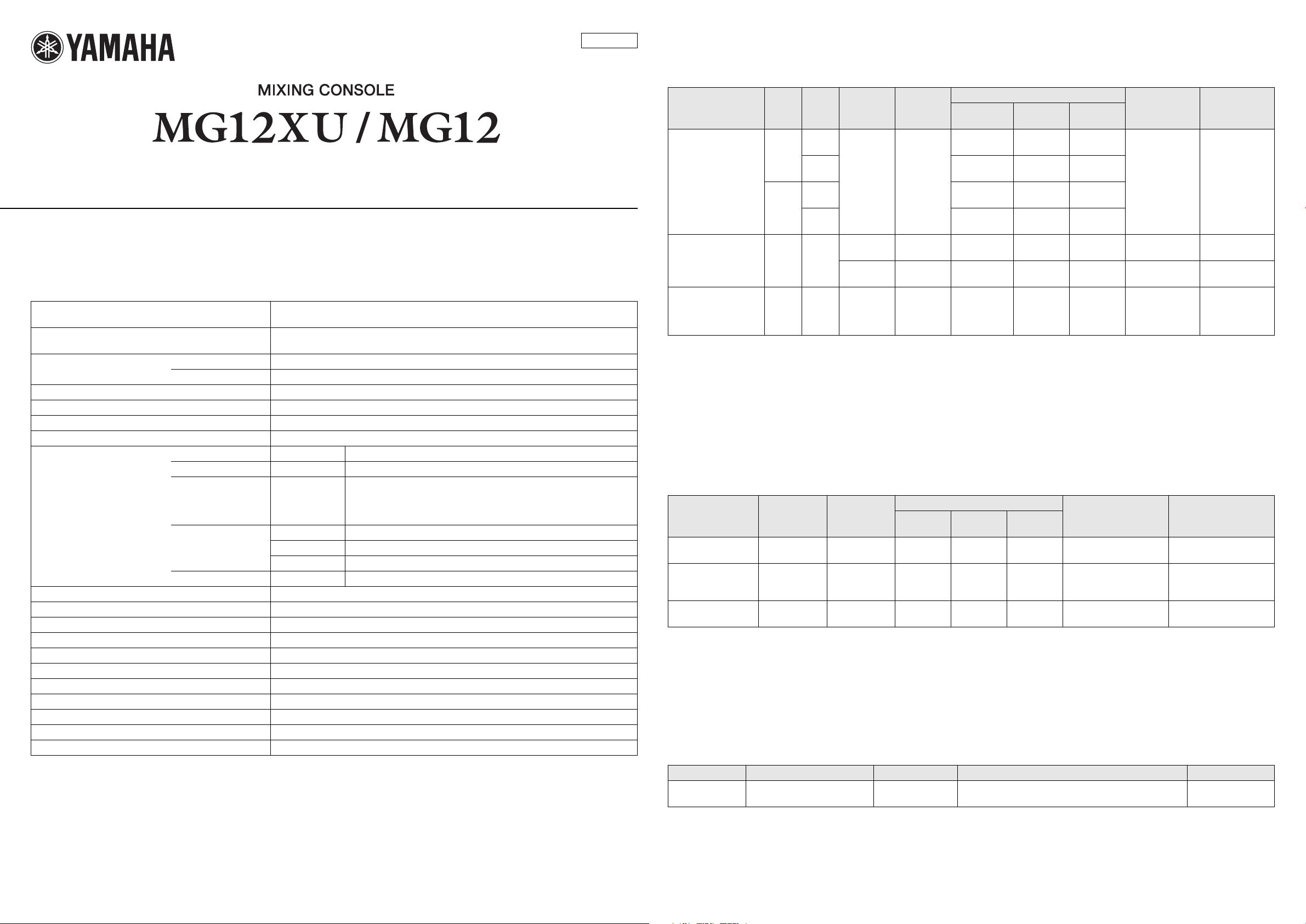
Analog Input Characteristics
Technical Specifications
General Specifications
0 dBu = 0.775 Vrms, Output impedance of signal generator (Rs) = 150 Ω
All level controls are nominal if not specified.
Frequency Response Input to STEREO OUT +0.5 dB/-1.5 dB (20 Hz to 48 kHz) ,
refer to the nominal output level @ 1 kHz, GAIN knob: Min
Total Harmonic Distortion
(THD+N)
Hum & Noise
(20 Hz to 20 kHz)
Crosstalk(1 kHz)
Input channels Mono [MIC/LINE]: 4, Mono/Stereo [MIC/LINE]: 2, Stereo [LINE]: 2
Output channels STEREO OUT: 2, MONITOR OUT: 1, PHONES: 1, AUX SEND: 2, GROUP OUT: 2
Bus STEREO : 1, GROUP: 2, AUX: 2 (MG12XU: incl. FX)
Input Channel Function PAD CH 1 – CH 4 26 dB
Level Meter Pre Monitor LEVEL 2 × 12 -segment LED meter [PEAK, +10, +6, +3, 0, -3, -6, -10, -15, -20, -25, -30 dB]
Built-in Effect (MG12XU) SPX Algorithm 24 programs, PARAMETER control: 1, FOOT SW: 1 (FX RTN CH on/off)
USB Audio (MG12XU) 2 IN / 2 OUT USB Audio Class 2.0 compliant, Sampling Frequency: Max 192 kHz, Bit Depth: 24-bit
Phantom Power Voltage +48 V
Power Requirements AC 100-240 V, 50 Hz/60 Hz
Power Consumption 22 W
Dimensions (W × H × D) 308 mm × 118 mm × 422 mm (9.6" × 2.8" × 11.6")
Net Weight MG12XU: 4.2 kg (9.3 lbs.), MG12: 4.0 kg (8.8 lbs.)
Included Accessory Owner’s Manual, Technical Specifications, Cubase AI Download Information (MG12XU only)
Optional Accessory Rack-mount kit: RK-MG12, Foot Switch: FC-5
Operating Temperature 0 to +40 °C
*1 Noise is measured with A-weighting filter.
*2 Crosstalk is measured with 1 kHz band pass filter.
Specifications and descriptions in this document are for information purposes only. Yamaha Corp. reserves the right to change or
modify products or specifications at any time without prior notice. Since specifications, equipment or options may not be the same in every locale, please
check with your Yamaha dealer.
*1
*2
Input to STEREO OUT 0.03 % @ +14 dBu (20 Hz to 20 kHz), GAIN knob: Min
0.005 % @ +24 dBu (1 kHz), GAIN knob: Min
Equivalent Input Noise -128 dBu (Mono Input Channel, Rs: 150 Ω, GAIN knob: Max)
Residual Output Noise -102 dBu (STEREO OUT, STEREO master fader: Min)
-78 dB
HPF CH 1 – CH 7/8 80 Hz, 12 dB/oct (Mono/Stereo: MIC only)
COMP CH 1 – CH 4 1 knob compressor (Gain/Threshold/Ratio)
Threshold: +22 dBu to -8 dBu, Ratio: 1:1 to 4:1,
Output level: 0 dB to 7 dB, Attack time: approx. 25 msec,
Release time: approx. 300 msec
EQ CH 1 – CH 11/12 HIGH: Gain: +15 dB/-15 dB, Frequency: 10 kHz shelving
CH 1 – CH 7/8 MID: Gain: +15 dB/-15 dB, Frequency: 2.5 kHz peaking
CH 1 – CH 11/12 LOW: Gain: +15 dB/-15 dB, Frequency: 100 Hz shelving
PEAK LED CH 1 – CH 7/8 LED turns on when post EQ signal reaches 3 dB below clipping (+17 dBu)
Input Terminals
CH INPUT 1–4
CH INPUT 5/6, 7/8 — —
CH INPUT 9/10, 11/12 — — 10 kΩ
0 dBu is referenced to 0.775 Vrms.
*1 Sensitivity is the lowest level that will produce an output of +4dBu (1.228V) or the nominal output level when the unit is set to maximum gain.
(All level controls are maximum position.)
*2 1/Sleeve=GND, 2/Tip=HOT, 3/Ring=COLD
*3 Tip=HOT, Ring=COLD, Sleeve=GND
*4 Tip=Signal, Ring=GND, Sleeve=GND
PA D
26dB
OFF
ON
GAIN
Tri m
+64 dB
+20 dB
+38 dB
-6 dB
Actual
Load
Impedance
3 kΩ
3 kΩ
10 kΩ
For Use
With
Nominal
50–600 Ω
Mics/Lines
50–600 Ω
Mics
600 Ω
Lines
600 Ω
Lines
Sensitivity
-80 dBu
(0.077 mV)
-36 dBu
(12.3 mV)
-54 dBu
(1.55 mV)
-10 dBu
(245 mV)
-80 dBu
(0.077 mV)
-54 dBu
(1.55 mV)
-30 dBu
(24.5 mV)
Input level
*1
(0.775 mV)
(122.8 mV)
(15.46 mV)
(0.775 mV)
(15.46 mV)
Nominal
-60 dBu
-16 dBu
-34 dBu
+10 dBu
(2.451 V)
-60 dBu
-34 dBu
-10 dBu
(245 mV)
Max.
before clip
-40 dBu
(7.75 mV)
+4 dBu
(1.228 V)
-14 dBu
(154.6 mV)
+30 dBu
(24.51 V)
-40 dBu
(7.75 mV)
-14 dBu
(154.6 mV)
+10 dBu
(2.45 V)
Jack
XLR-3-31
TRS PHONE
(6.3 mm)
Combo type
XLR-3-31
TRS PHONE
(6.3 mm)
TRS PHONE
(6.3 mm)
RCA PIN
*2
*3
*2
*4
*4
Unbalanced
XLR-3-31:
TRS PHONE:
TRS PHONE:
RCA PIN:
Analog Output Characteristics
Output Terminals
STEREO OUT L, R 75 Ω 600 Ω Lines —
MONITOR OUT L, R
GROUP OUT 1–2
AUX SEND 1–2
PHONES L, R 110 Ω 40 Ω Lines —
0 dBu is referenced to 0.775 Vrms.
*2 1/Sleeve=GND, 2/Tip=HOT, 3/Ring=COLD
*3 Tip=HOT, Ring=COLD, Sleeve=GND
*5 Tip=LEFT, Ring=RIGHT, Sleeve=GND
Actual Source
Impedance
150 Ω 10 kΩ Lines —
For Use
With Nominal
— Nominal
Output level
+4 dBu
(1.228 V)
+4 dBu
(1.228 V)
3 mW +
3 mW
Max.
before clip
+24 dBu
(12.28 V)
+20 dBu
(7.750 V)
100 mW +
100 mW
Jack
XLR-3-32
TRS PHONE(6.3 mm)
TRS PHONE(6.3 mm)
TRS PHONE(6.3 mm)
*2
Balanced / Unbalanced /
Impedance Balanced
*3
*3
*5
Balanced
Impedance
Balanced
Digital Input / Output Characteristics (MG12XU)
Termina ls Format Data length
USB
*1 Data length depends on the particular audio format being used. USB Audio Class 2.0: 16-bit/24-bit, Yamaha Steinberg USB Driver: 24-bit
USB Audio Class 2.0/
Yamaha Steinberg USB Driver
16-bit/24-bit 44.1 kHz, 48 kHz, 88.2 kHz, 96 kHz, 176.4 kHz, 192 kHz USB Standard-B
*1
Fs Connector
Balanced /
Balanced
Balanced
Unbalanced
Unbalanced
Unbalanced
—
European Models
Inrush Current based on EN 55103-1:2009
3.0 A (on initial switch-on)
2.0 A (after a supply interruption of 5s)
Conforms to Environments: E1, E2, E3 and E4
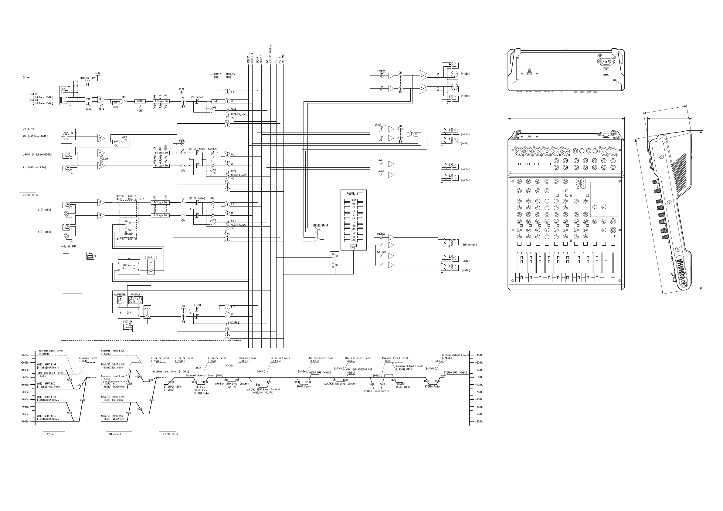
Block and Level Diagrams
USB
MONO/ST CH INPUT
MONO CH INPUT MONO/ST CH INPUT
MONO CH INPUT (MIC/LINE)
ST CH INPUT
SEND AUX2
SEND AUX1
GROUP OUT 1
GROUP OUT 2
STEREO OUT L
STEREO OUT R
Digital EFFECT
PHONES
MONITOR OUT L
MONITOR OUT R
ST CH INPUT
Dimensions
115
308 118
422
416
Unit: mm
This illustration shows the MG12XU.
C.S.G., PA Development Division
© 2014 Yamaha Corporation
401POAP*.*-01A0
Printed in Vietnam
 Loading...