

Yamaha EF7200E, EF7200DE, EF7200 Owner's Manual

OWNER’S MANUAL
E
MANUEL D’UTILISATION
BEDIENUNGSANLEITUNG
MANUALE PER IL PROPRIETARIO
Read this manual carefully before operating this machine.
Il convient de lire attentivement ce manuel avant la première utilisation de la machine.
Bitte lesen Sie diese Bedienungsanleitung sorgfältig durch, bevor Sie die Maschine in Betrieb nehmen.
Leggere attentamente questo manuale prima di utilizzare questa macchina.
F
D
I
EF7200DE
EF7200E
EF7200
7P6-F8199-U0

OWNER’S MANUAL
Read this manual carefully before operating this machine.
EF7200DE
EF7200E
EF7200
7P6-F8199-U0-E0

Read this manual carefully before operating this machine. This manual should
stay with this machine if it is sold.

INTRODUCTION
Congratulations on your purchase of your new Yamaha.
This manual will provide you with a good basic understanding of the operation and
maintenance of this machine.
If you have any questions regarding the operation or maintenance of your machine,
please consult a Yamaha dealer.
EF7200DE/EF7200E/EF7200
OWNER’S MANUAL
©2014 by Yamaha Motor Powered
Products Co., Ltd.
1st Edition, January 2014
All rights reserved.
Any reprinting or unauthorized use
without the written permission of
Yamaha Motor Powered
Products Co., Ltd.
is expressly prohibited.
Printed in China
IMPORTANT MANUAL INFORMATION
Particularly important information is distinguished in this manual by the following
notations.
This is the safety alert symbol. It is
used to alert you to potential personal
injury hazards. Obey all safety messages that follow this symbol to avoid possible injury or death.
WARNING
A WARNING indicates a hazardous situation which, if not avoided, could
result in death or serious injury.
NOTICE
A NOTICE indicates special precautions that must be taken to avoid damage to the machine or other property.
TIP
A TIP provides key information to make
procedures easier or clearer.
WARNING
PLEASE READ AND UNDERSTAND
THIS MANUAL COMPLETELY BEFORE
OPERATING THE MACHINE.
TIP
9 Yamaha continually seeks advance-
ments in product design and quality.
Therefore, while this manual contains
the most current product information
available at the time of printing, there
may be minor discrepancies between
your machine and this manual. If
there is any question concerning this
manual, please consult a Yamaha
dealer.
9 This manual should be considered a
permanent part of this machine and
should remain with this machine
when resold.
* Product and specifications are subject to
change without notice.

CONTENTS
SAFETY INFORMATION ...................... 1
Exhaust fumes are poisonous ............ 2
Fuel is highly flammable and
poisonous ........................................... 2
Engine and muffler may be hot .......... 2
Electric shock prevention ................... 3
Connection notes ............................... 4
Connection ......................................... 4
Extension cord notes .......................... 4
LOCATION OF IMPORTANT
LABELS ................................................ 5
DESCRIPTION ...................................... 7
Control panel (For EF7200DE) .......... 8
Control panel (For EF7200E) ............. 8
Control panel (For EF7200) ............... 8
CONTROL FUNCTION ......................... 9
Engine switch ..................................... 9
Oil warning light (Red)........................ 9
AC switch (N.F.B.) ............................ 10
Fuel tank cap .................................... 10
Fuel cock lever ................................. 11
Ground (earth) terminal.................... 11
Economy control switch
(Except for EF7200) ......................... 12
Choke lever (For EF7200) ................ 12
Recoil starter .................................... 13
Voltage adjuster ............................... 13
PREPARATION ................................... 14
Fuel .................................................. 14
Engine oil .........................................15
Battery (Except for EF7200) ............. 16
Ground (earth) terminal.................... 17
PRE-OPERATION CHECK ................. 18
Pre-operation check ......................... 18
OPERATION ....................................... 19
Starting the engine ........................... 19
Stopping the engine ......................... 22
Connection ....................................... 24
Application range ............................. 26
PERIODIC MAINTENANCE ................ 27
Maintenance chart ........................... 27
Carburetor adjustment ..................... 29
Spark plug inspection ....................... 29
Engine oil replacement ..................... 30
Air filter ............................................. 32
Muffler screen .................................. 33
Fuel cock .......................................... 34
Fuel tank filter ................................... 35
Battery (Except for EF7200) ............. 36
Recommended battery
(Except for EF7200) ......................... 37
Fuse replacement
(Except for EF7200) ......................... 37
STORAGE ........................................... 38
Drain the fuel .................................... 38
Engine .............................................. 40
Battery (Except for EF7200) ............. 41
TROUBLESHOOTING ........................ 42
SPECIFICATIONS ............................... 48
Dimensions ...................................... 48
Engine .............................................. 48
Generator ......................................... 49
CONSUMER INFORMATION.............. 50
Identification number records ........... 50
Machine identification ....................... 50
WARRANTY ........................................ 51
WIRING DIAGRAM ............................. 52
EF7200DE ........................................ 52
EF7200E .......................................... 53
EF7200 ............................................. 54
SAFETY INFORMATION
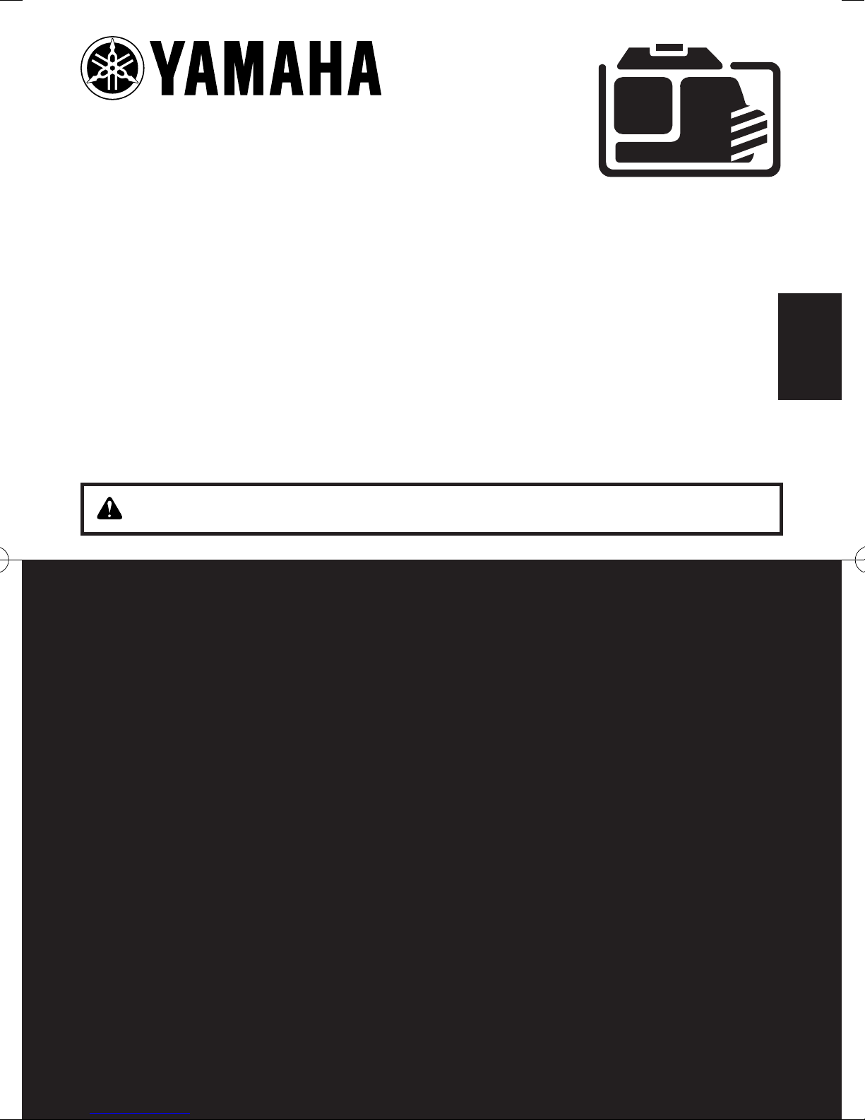
9 This generator is not designed for on-board use.
Do not use it while installed on the vehicle.
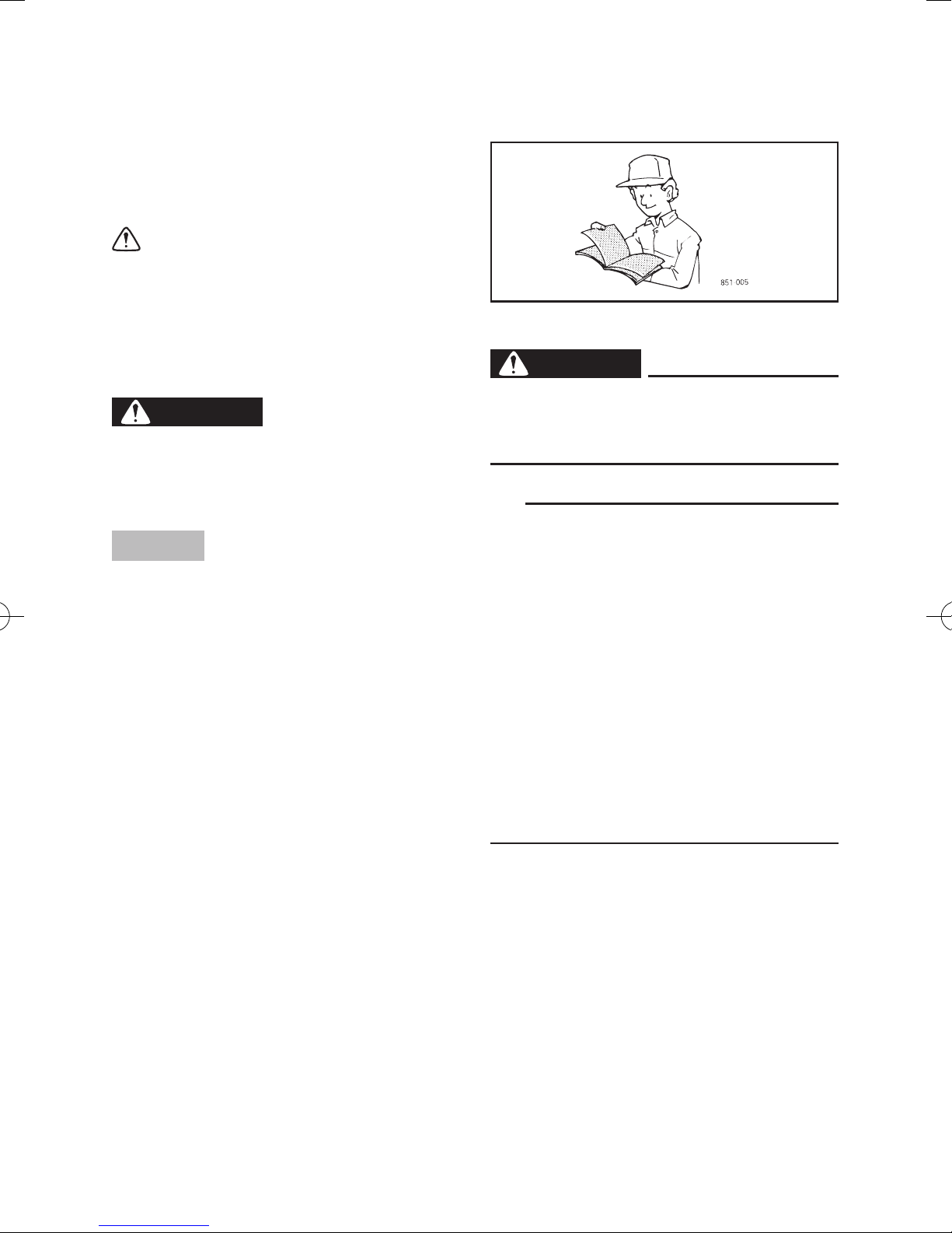
9 Do not modify the generator or use it with its parts
removed.
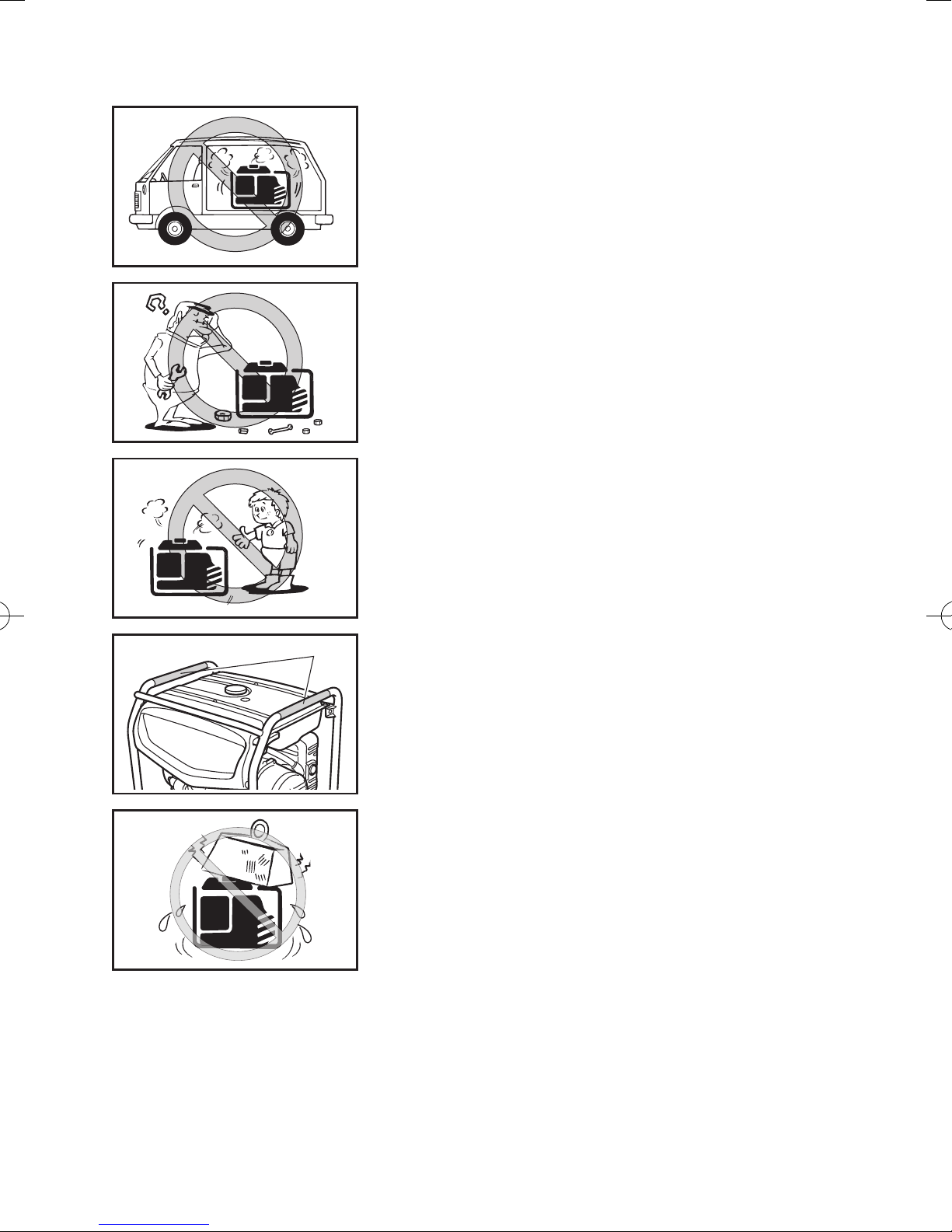
9 Do not allow children to operate the generator.
1
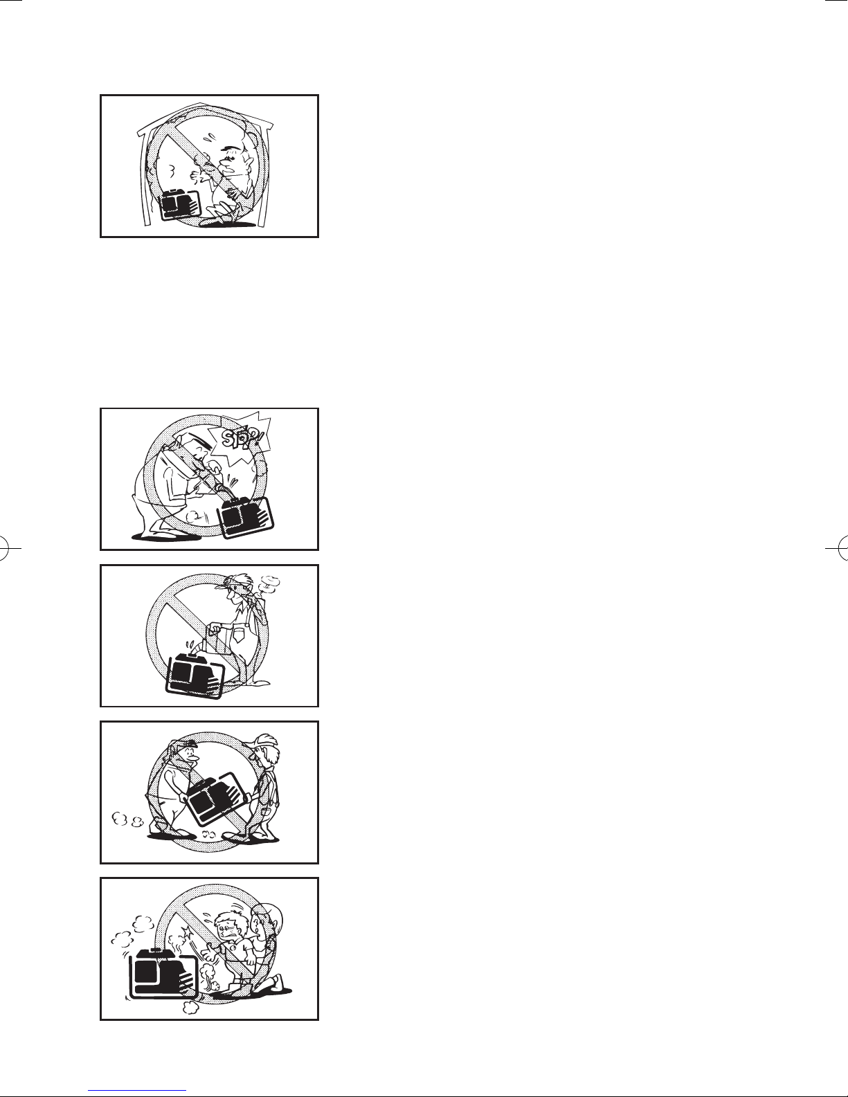
9 Be sure to carry the generator only by its carrying
handle(s).
1 Carrying handle(s) (shaded)
9 Do not place any obstacles on the generator.
– 1 –
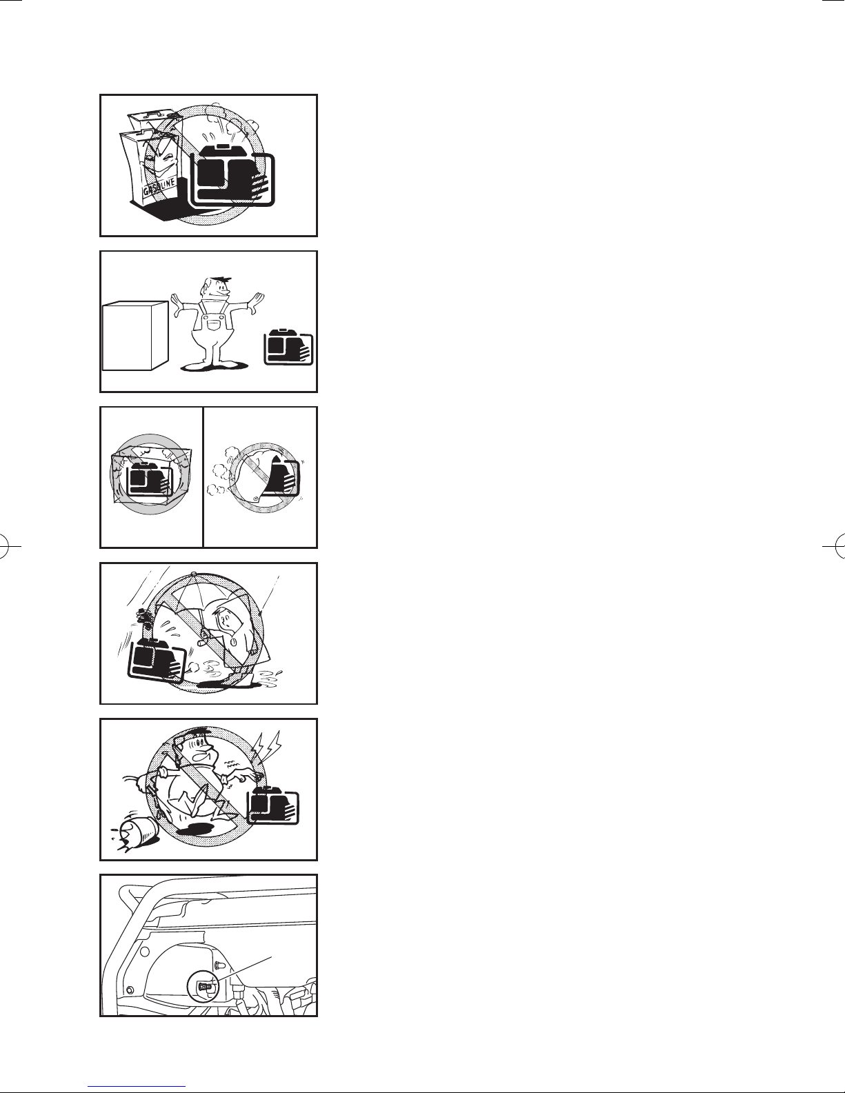
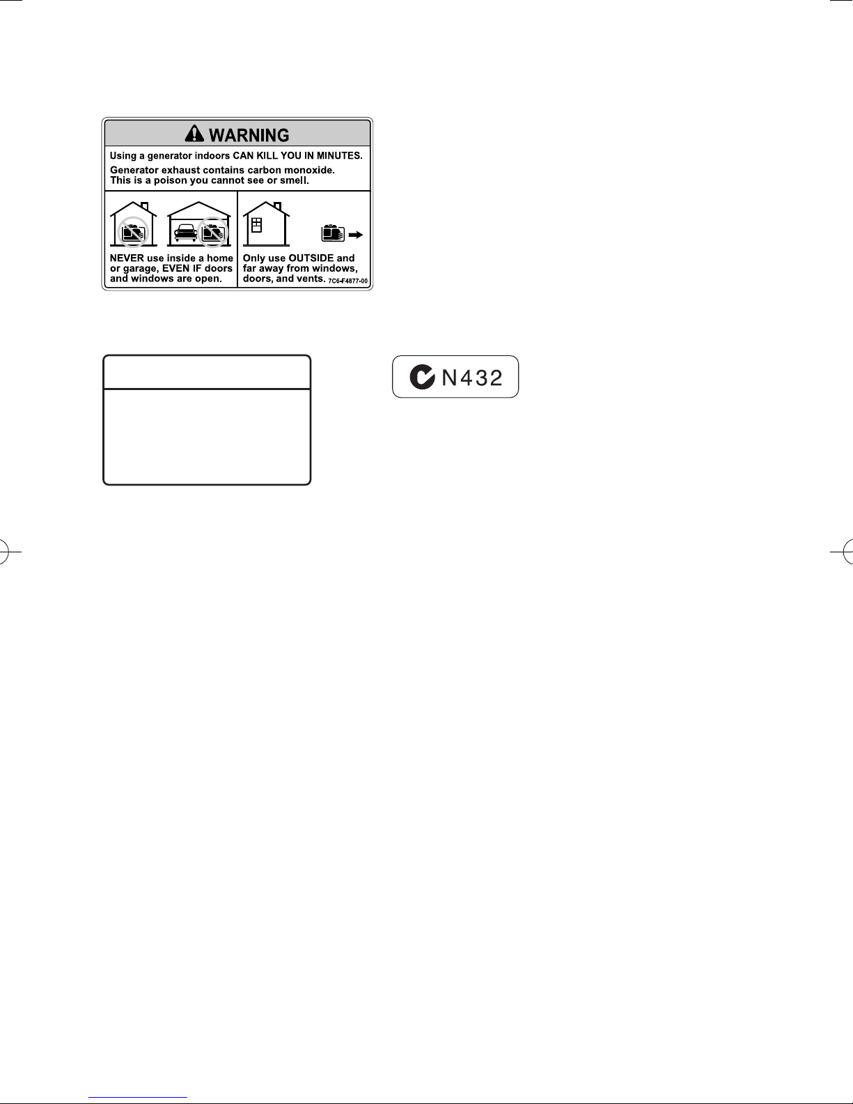
Exhaust fumes are poisonous
9 Using a generator indoors CAN KILL YOU IN
MINUTES. Generator exhaust contains carbon
monoxide. This is a poison you cannot see or
smell.
741-002
741-003
9 NEVER use inside a home or garage, EVEN IF
doors and windows are open.
9 Only use OUTSIDE and far away from windows,
doors, and vents.
Fuel is highly flammable and poisonous
9 Always turn off the engine when refuelling.
9 Never refuel while smoking or in the vicinity of an
open flame.
9 Take care not to spill any fuel on the engine or
muffler when refuelling.
9 Do not leave the generator inside the vehicle or in
the trunk.
741-005
741-004
741- 006
9 If you swallow any fuel, inhale fuel vapor, or allow
any to get in your eye(s), see your doctor immediately. If any fuel spills on your skin or clothing,
immediately wash with soap and water and
change your clothes.
9 When operating or transporting the generator, be
sure it is kept upright. If it tilts, fuel may leak from
the carburetor or fuel tank.
Engine and muffler may be hot
9 Place the generator in a place where pedestrians
or children are not likely to touch the generator.
– 2 –
741-007
741-008a
7CC-001
9 Avoid placing any flammable materials near the
exhaust outlet during operation.
9 In order to prevent overheating, ensure adequate
airflow by keeping the machine at least 1 m (3 ft)
from objects or other equipment.
9 Do not operate the engine with a dust cover or
other objects covering it.
9 When covering the generator, be sure to do so
only after the engine and muffler have completely
cooled down.
741-010
741-011
1
Electric shock prevention
9 Never operate the engine in rain or snow.
9 Never touch the generator with wet hands or elec-
trical shock will occur.
9 Connect the ground (earth) terminal to a ground
source. In order to prevent electrical shock, the
generator must be grounded when using a
grounded electrical device.
1 Ground (earth) terminal
– 3 –
1
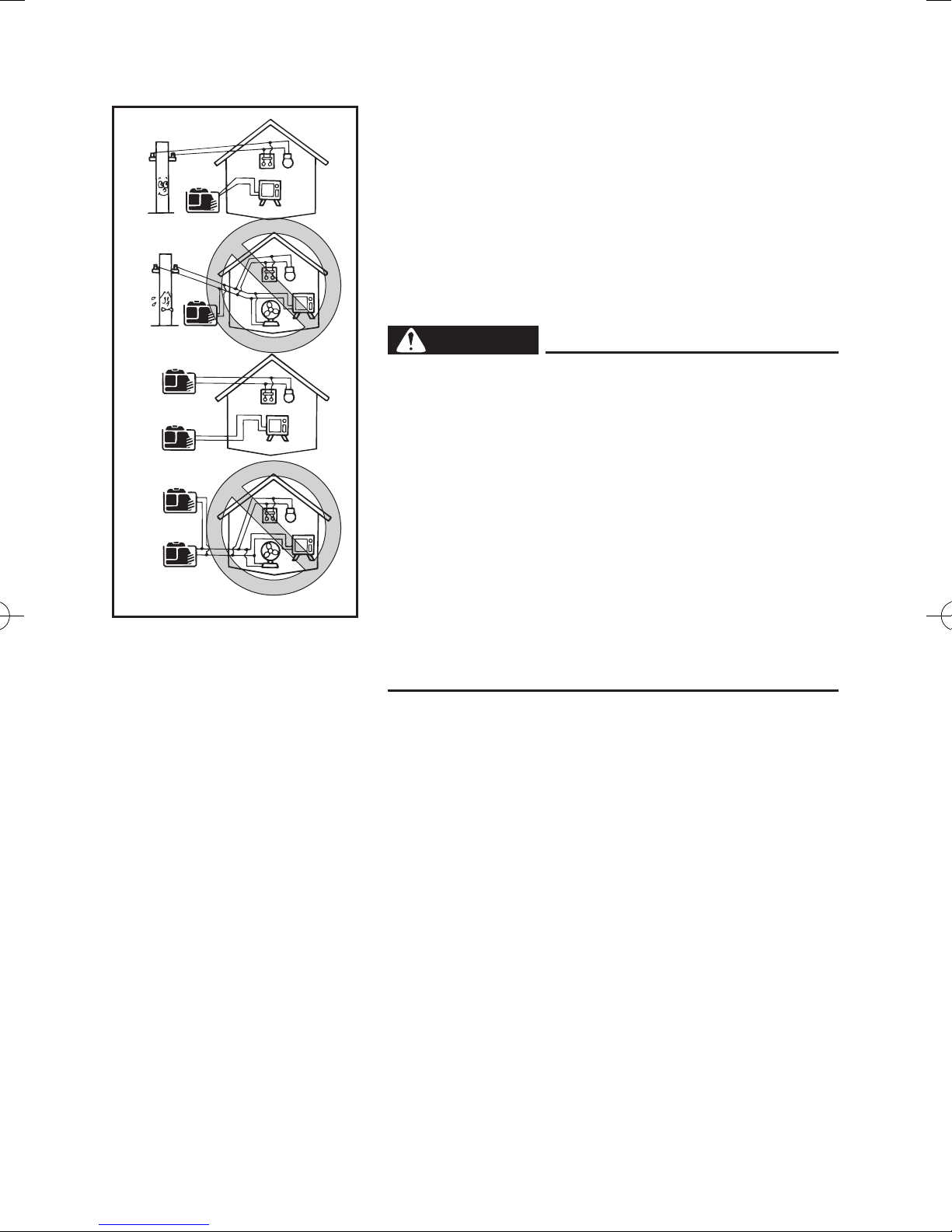
Connection notes
9 Avoid connecting the generator to commercial
power outlet.
9 Avoid connecting the generator in parallel with any
other generator.
2
1
2
741-040a
1 Correct
2 Incorrect
Connection
WARNING
Before the generator can be connected to a building’s electrical system, a licensed electrician must
install an isolation (transfer) switch in the building’s main fuse box. The switch is the connection
point for generator power and allows selection of
generator or main line power to the building. This
will prevent the generator from charging the main
power line (backfeeding) when the main power
supply has failed or has been turned off for line
repair. Backfeeding can electrocute or injure line
maintenance personnel. Also, generator and building electrical system damage can occur when normal operating power returns if unit is used without
an isolation switch.
Extension cord notes
Extension cords should be protected by a tough flexible rubber sheath (IEC 245) or the equivalent to withstand mechanical stresses.
– 4 –
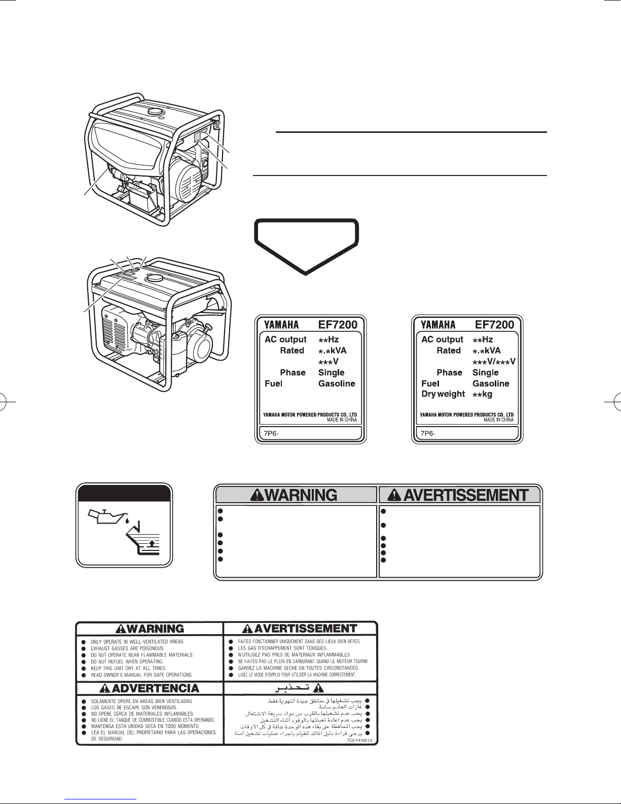
LOCATION OF IMPORTANT LABELS
Please read the following labels carefully before operating this generator.
TIP
Maintain or replace safety and instruction labels, as
1
necessary.
2
3
4
3
5
6 7
1
HOT EXHAUST
2 (Except for EF7200DE)
4 (For OCEANIA)
2 (For EF7200DE)
O I L
4 (Except for OCEANIA)
RE AD TH E OW NE R' S M AN UA L AND A LL L ABE LS B EF ORE O PE RA TI NG.
ON LY OP ER AT E IN WE LL -V EN TIL AT ED A REA S.
EXHAU ST GAS CO NTA INS PO ISO NOU S CARBON MO NOX IDE .
CH EC K FOR S PI LL ED F UE L O R FU EL L EA KS .
ST OP E NG IN E BE FO RE R EF UE LI NG .
DO NOT OP ERA TE NE AR FLAM MA BLE M ATE RI ALS.
EL ECT ROC UTI ON CAN OC CU R IF GEN ERA TO R IS USE D I N RA IN,
SN OW, O R N EA R W AT ER. K EEP T HIS U NIT D RY AT AL L T IM ES.
– 5 –
LIS E Z L E MO DE D 'E MP LO I E T TO UT ES L ES E TI Q UE TT ES A VA NT D E
FA IRE FO NCT ION NER LA M AC HIN E.
FA ITE S F ONC TIO NNE R U NI QU EME NT DAN S DE S L IEU X B IE N AER ES.
LE S GAZ D 'E CHAPP EM EN T C ON TI ENNEN T DU MO NO XI DE DE C AR BON E.
V ER IF IE Z S I DU C AR B UR AN T A E TE R EN V ERS E OU S' IL F UI T .
AR RET EZ L E MOT EU R AVAN T DE FAI RE LE P LE IN D E CA RBUR AN T.
N'U T IL IS EZ P AS A P RO XI MI TE D E MA TE RI AU X IN FL AM MA BL ES .
IL Y A R IS QU E D' EL EC TR OC UT IO N SI L E GE NE RA TE UR F ON CT IO NE
SO US LA P LU IE, D AN S LA N EI GE, OU PR ES D E L' EA U. GAR DE Z LA
MA CHI NE AU SE C E N TOU TE S C IR CON ST ANC ES .
7C3 -F41 62-10
5 (For OCEANIA)
6 (For OCEANIA)
q
WARNING
THE OUTPUT OF THIS GENERATING SET IS
POTENTIALLY LETHAL. THE SET SHOULD
NOT BE CONNECTED TO A FIXED ELECTRICAL
INSTALLATION EXCEPT BY AN APPROPRIATELY
LICENSED PERSON.
7 (For OCEANIA)
– 6 –
EF7200E, EF7200DE
1
9
0
2
8
3
4
q
1
7
5
6
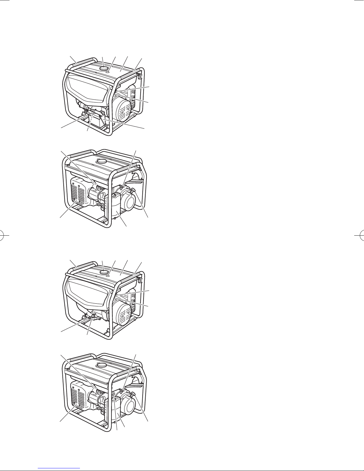
DESCRIPTION
1 Carrying handles (shaded)
2 Fuel tank cap
3 Fuel level gauge
4 Fuel tank
5 Voltage adjuster
6 Ground (earth) terminal
7 Battery (For EF7200E, EF7200DE)
8 Oil filler cap
9 Oil drain bolt
0 Spark plug
q Fuel cock
w Recoil starter handle
e Air filter case cover
r Choke lever (For EF7200)
t Muffler
t
EF7200
9
0
1
8
2
3
e
4
w
1
5
6
q
t
r
e
w
– 7 –
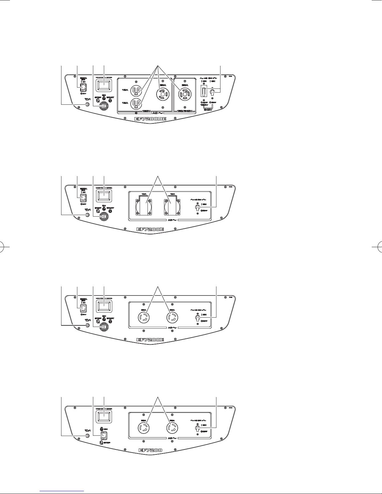
EF7200DE
32 41 5 6
Control panel
(For EF7200DE)
1 Oil warning light (Red)
2 Economy control
switch
3 Engine switch
4 Voltage/hour meter
5 AC receptacle
6 AC switch (N.F.B.)
000-000
EF7200E (For OCEANIA)
32 41 5 6
EF7200E (Except for OCEANIA)
32 41 5 6
Control panel
(For EF7200E)
1 Oil warning light (Red)
2 Economy control
switch
3 Engine switch
4 Voltage/hour meter
5 AC receptacle
6 AC switch (N.F.B.)
000-000
EF7200
2 31 4 5
000-000
Control panel
(For EF7200)
1 Oil warning light (Red)
2 Engine switch
3 Voltage/hour meter
4 AC receptacle
5 AC switch (N.F.B.)
000-000
– 8 –
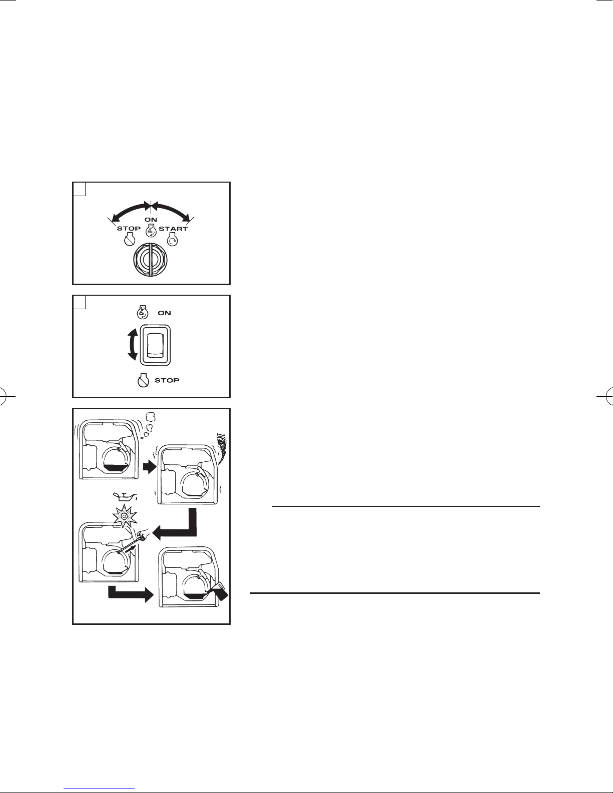
CONTROL FUNCTION
Engine switch
The engine switch controls the ignition system.
1 “7” (ON)
Ignition circuit is switched on.
The engine can be started.
A
2
1
3
2 “5” (STOP)
Ignition circuit is switched off.
The engine will not run.
3 “6” (START)
763-119
Starting circuit is switched on.
After starting the engine, take your hand off the switch
B
1
2
immediately.
å EF7200E/EF7200DE
∫ EF7200
Oil warning light (Red)
When the oil level falls below the lower level, the oil
warning light comes on and then the engine stops
automatically. Unless you refill with oil, the engine will
not start again.
700-027c
TIP
If the engine stalls or does not start, turn the engine
switch to “7” (ON) and then pull the recoil starter or
turn the engine switch to “6” (START). If the oil warning light comes on, the engine oil is insufficient. Add oil
and restart.
– 9 –
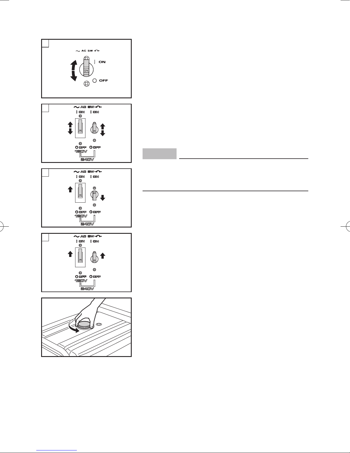
A
AC switch (N.F.B.)
The AC switch (Non-Fuse Breaker) turns off automati-
1
cally when the load exceeds the generator rated output.
2
763-252a
B
1
2
1
2
1 “I” (ON)
2 “3” (OFF)
å EF7200/EF7200E
∫ EF7200DE
ç supplies AC 120 V (EF7200DE)
∂ supplies AC 120 V and 240 V (EF7200DE)
NOTICE
Reduce the load to the specified generator rated
C
1
2
D
1
1
output if the AC switch (N.F.B.) turns off. If it turns
off again, consult a Yamaha dealer.
Fuel tank cap
Remove the fuel tank cap by turning it counterclockwise.
– 10 –
1
Fuel cock lever
The fuel cock supplies fuel from the fuel tank to the
carburetor.
22
7DF-106
The fuel cock has two positions.
1 ON
With the lever in this position, fuel flows to the carburetor. Normal using is done with the lever in this position.
2 OFF
With the lever in this position, fuel will not flow. Always
turn the lever to this position when the engine is not
running.
Ground (earth) terminal
Ground (earth) terminal connects the earth line for
prevention of electric shock.
1
When the electric device is earthed, always the generator must be earthed.
1 Ground (earth) terminal
– 11 –
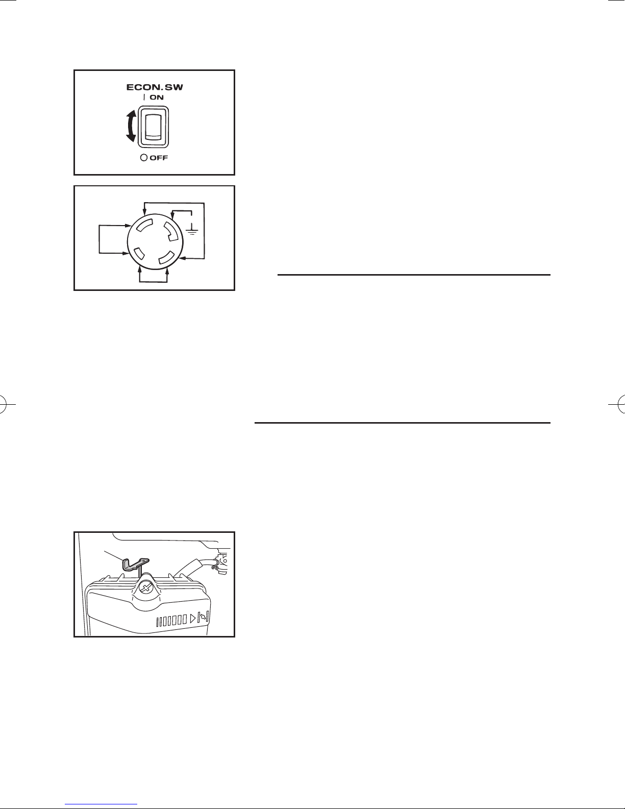
Economy control switch (Except for EF7200)
120V
1
2
Y
W
120V
G
X
240V
GR
1 “I” (ON)
When the economy control switch is turned to “I” (ON),
the economy control unit controls the engine speed
according to the connected load. The results are better
fuel consumption and less noise.
2 “3” (OFF)
When the economy control switch is turned to “3”
(OFF), the engine runs at the rated r/min (3600 r/min)
regardless of whether there is a load connected or not.
TIP
9 The economy control switch must be turned to “3”
(OFF) when using electric devices that require a
large starting current, such as a compressor or a
submersible pump.
9 The economy control switch must be turned to “3”
(OFF) to increase engine speed to rated r/min
when:
- using a load of 0.8 A or less.
- supplying AC 120 V only from W with X.
1
Choke lever (For EF7200)
Starting a cold engine requires a richer air-fuel mixture, which is supplied by the choke lever.
1 Choke lever
– 12 –

1
Recoil starter
The recoil starter is used to start the engine.
Pull the recoil starter slowly until it is engaged, then
pull it briskly.
1 Recoil starter handle
NOTICE
9 Pull the recoil starter handle straight.
9 Return the recoil starter handle slowly.
9 Do not touch the recoil starter handle while the
generator is operating.
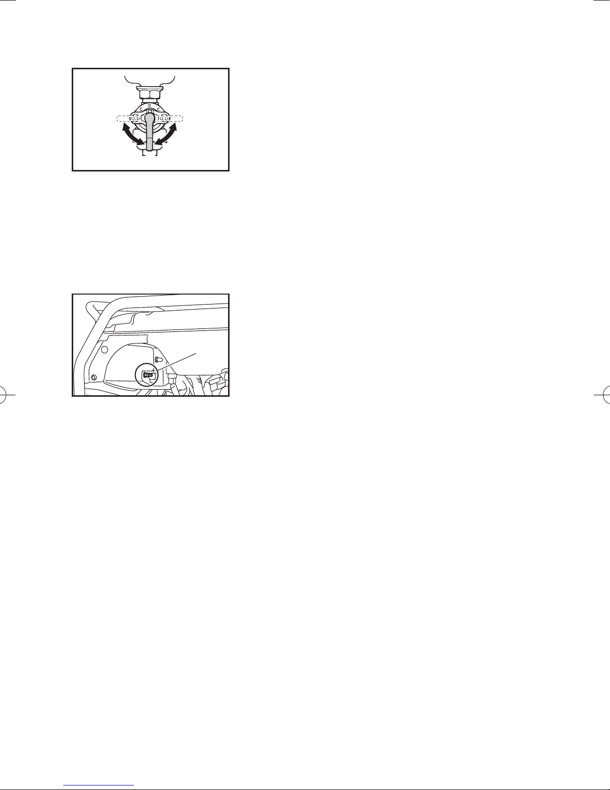
Voltage adjuster
The voltage adjuster is equipped for adjusting output
voltage to rated voltage.
TIP
000-000
Turn the voltage adjuster clockwise or counterclockwise to increase or decrease output voltage.
– 13 –

PREPARATION
Fuel
WARNING
9 Fuel is highly flammable and poisonous.
Check “SAFETY INFORMATION” (See page 2)
carefully before filling.
9 Do not overfill the fuel tank, otherwise it may
overflow when the fuel warms up and expands.
9 Wipe up any spilled fuel immediately.
9 After filling the tank with fuel, make sure the
fuel tank cap is tightened securely.
1. Stop the engine.
2. Place the generator on a level surface.
3. Remove the fuel tank cap.
4. Check the fuel level.
5. If low, fill the tank with fuel.
1 2
NOTICE
9 Immediately wipe off spilled fuel with a clean,
dry, soft cloth, since fuel may deteriorate paint-
ed surfaces or plastic parts.
9 Use only unleaded gasoline. The use of leaded
gasoline will cause severe damage to internal
engine parts.
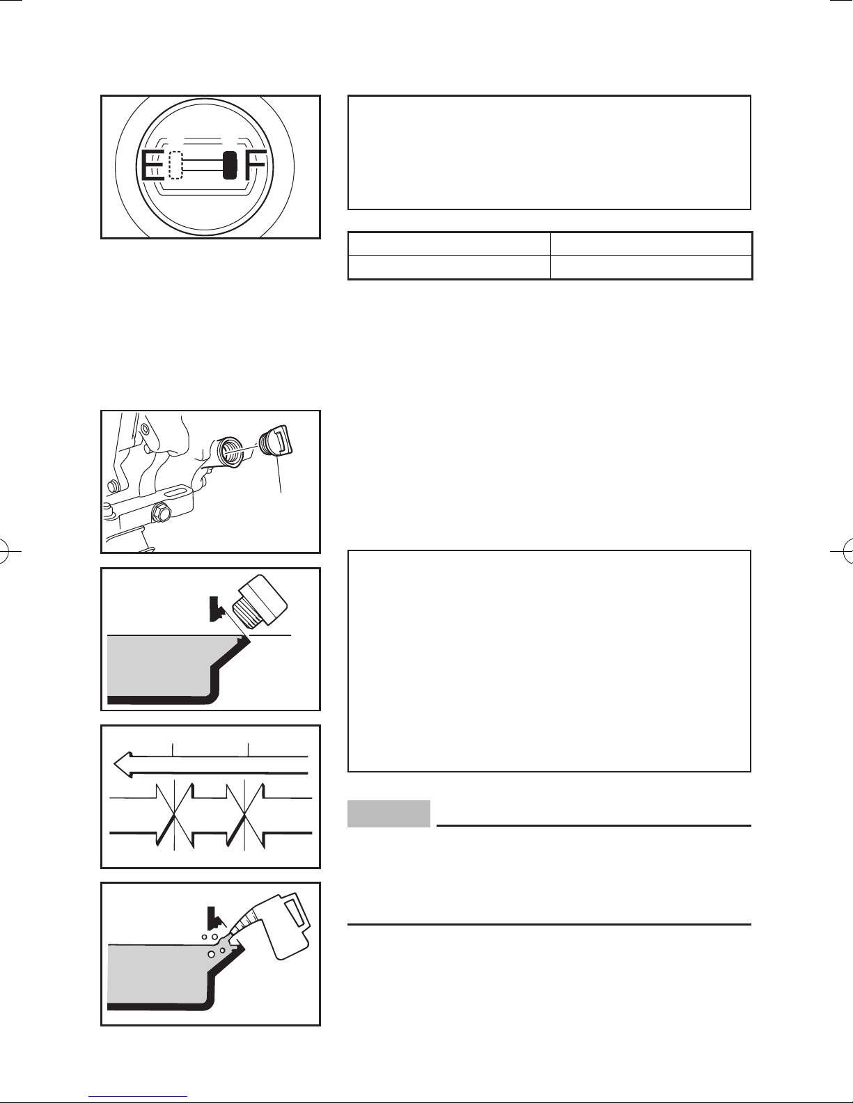
Make sure there is sufficient fuel in the tank.
When refueling, do not fill the tank up above the top
edge of the fuel tank filter.
1 Fuel level
2 Fuel tank filter
3 Fuel level gauge
3
– 14 –
5
4
7DK-093
Recommended fuel:
Unleaded gasoline
Fuel tank capacity:
Total:
28 L (7.40 US gal, 6.16 Imp gal)
4
“F” Full
5
“E” Empty
Engine oil
Make sure the engine oil is at the correct level of the
oil filler hole.
0°C
A
YAMALUBE 4 (10W-40)
D
SAE 10W
32°F
C
SAE #20
25°C
80°F
B
SAE #30
1
700-110a
2
1 Oil filler cap
2 Correct level
Recommended engine oil:
å YAMALUBE 4 (10W-40),
SAE 10W-30 or 10W-40
∫ SAE #30
ç SAE #20
∂ SAE 10W
Recommended engine oil grade:
API Service SE type or higher
Engine oil quantity:
1.1 L (1.16 US qt, 0.97 Imp qt)
NOTICE
The generator was shipped from the factory without engine oil. Do not start the engine for the first
time until the oil level has been checked and oil
added if necessary.
700-006
– 15 –
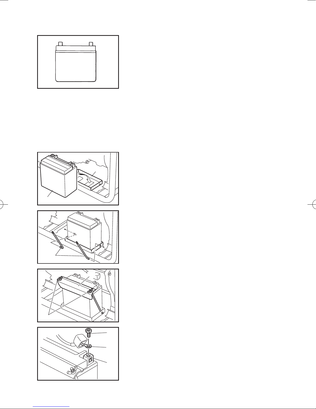
Battery (Except for EF7200)
(See page 36 for more details)
This generator is designed to be equipped with a
VRLA (Valve Regulated Lead Acid) battery. There is
no need to check the electrolyte or to add distilled
water.
Installation
1. Turn the engine switch to “5” (STOP) to prevent
accidental short circuiting.
2. Place the battery on the battery mount tray.
1
4
3
5
2
1 Battery
2 Battery mount tray
3. Install the battery mounting rods and battery
mounting plate, and then install and tighten the
wing nuts.
3 Battery mounting rod
4 Wing nut
5 Battery mounting plate
6
7
8
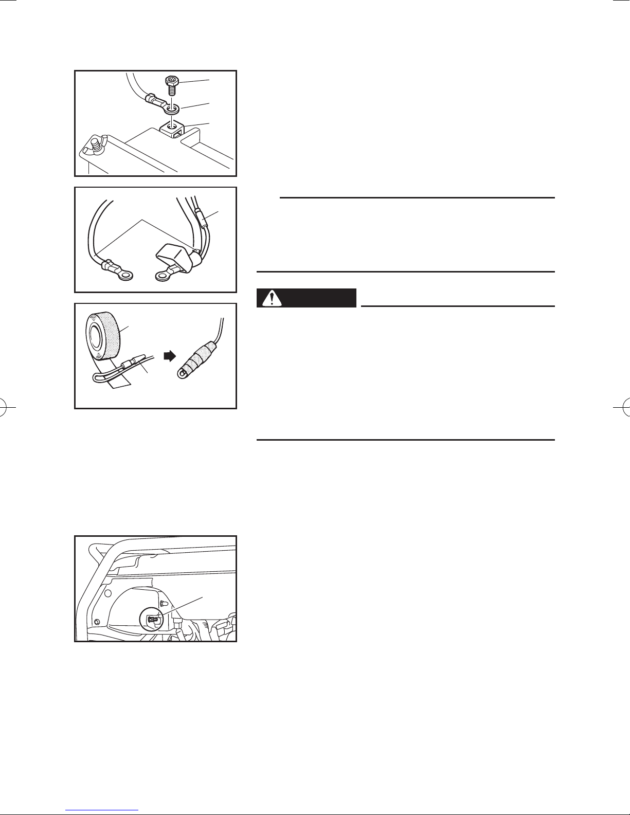
4. Connect the positive lead (Red) to the positive (+)
battery terminal.
6 Screw
7 Positive lead (Red)
8 Positive battery terminal
– 16 –
9
0
5. Connect the negative lead (Black) to the negative
(–) battery terminal.
r
e
w
q
w
762-004
762-005
9 Screw
0 Negative lead (Black)
q Negative battery terminal
TIP
Connect the positive lead (Red) to the positive (+) battery terminal first, then the negative lead (Black) to the
negative (–) battery terminal. Do not reverse these
positions.
WARNING
9 Be sure to insulate battery leads to prevent
arcing when the battery is not installed.
9 Disconnect the battery charging output lead.
Then insulate the connector by folding it back
on itself and carefully wrapping it with electri-
cal tape to prevent electrical contact with
ground (earth) or any other leads.
9 Remove the battery leads from the generator.
1
w Connector
e Battery lead
r Electrical tape
Ground (earth) terminal
Make sure to ground (earth) the generator.
Check “SAFETY INFORMATION” (See page 3).
1 Ground (earth) terminal
– 17 –

PRE-OPERATION CHECK
WARNING
If any item in the Pre-operation check is not working properly, have it inspected and repaired before
operating the generator.
The condition of a generator is the owner’s responsibility. Vital components can start to deteriorate quickly
and unexpectedly, even if the generator is unused.
TIP
Pre-operation checks should be made each time the
generator is used.
Pre-operation check
Fuel (See page 14)
9 Check fuel level in fuel tank.
9 Refuel if necessary.
Fuel line
9 Check fuel hose for crack or damage.
9 Replace if necessary.
Engine oil (See page 15)
9 Check oil level in engine.
9 If necessary, add recommended oil to specified
level.
9 Check generator for oil leakage.
The point where abnormality was recognized by
use
9 Check operation.
9 If necessary, consult a Yamaha dealer.
– 18 –
OPERATION
WARNING
9 Never operate the engine in a closed area or it
may cause unconsciousness and death within
a short time. Operate the engine in a well ven-
tilated area.
9 Before starting the engine, do not connect any
electric devices.
9 Clean dusts, dirt or water off the receptacle
before use.
NOTICE
The generator was shipped from the factory with-
A
out engine oil. Do not start the engine for the first
time until the oil level has been checked and oil
added if necessary.
1
1
Starting the engine
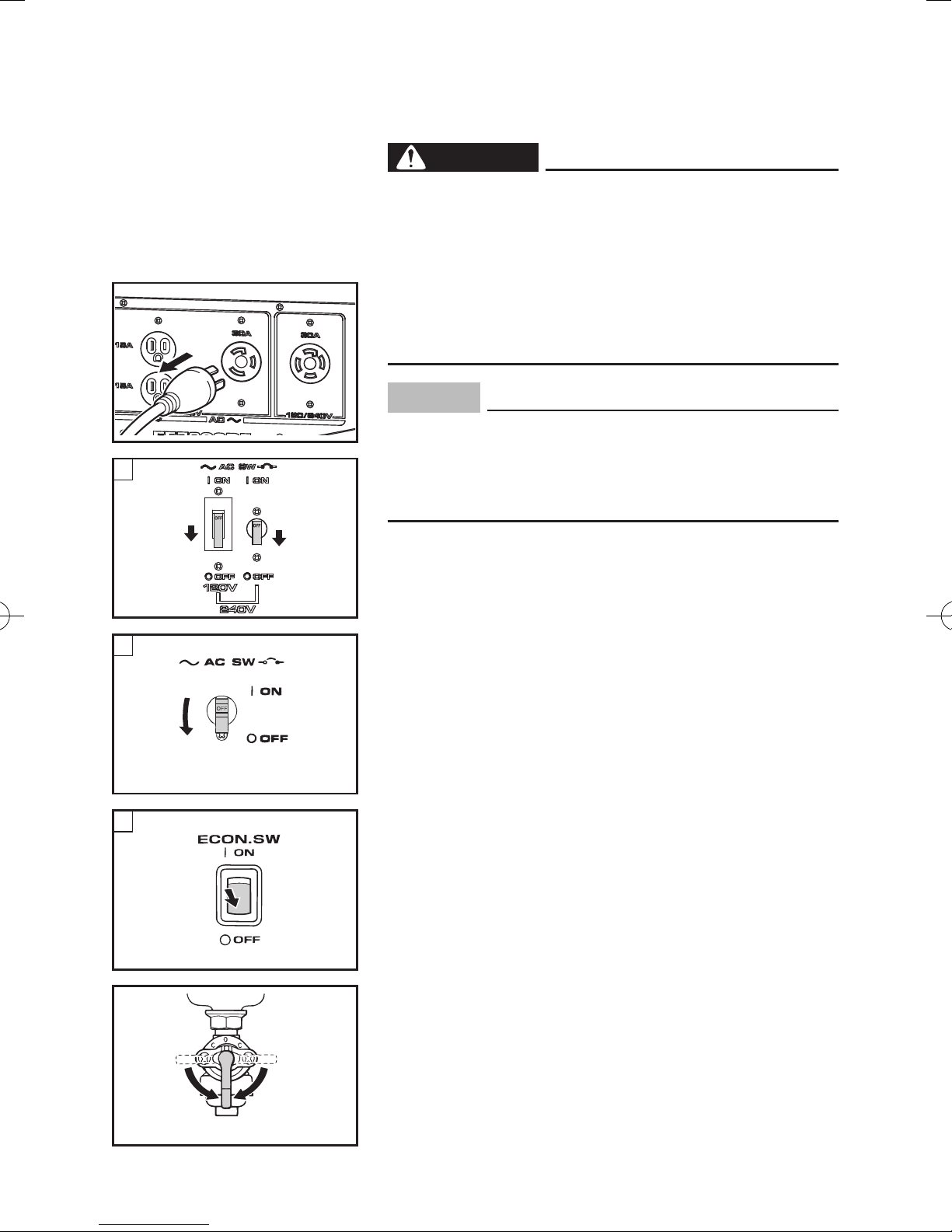
1. Turn the AC switch (N.F.B.) and economy control
switch to “3” (OFF).
B
1
763-252b
C
1
1 “3” (OFF)
å AC switch (N.F.B.) (For EF7200DE)
∫ AC switch (N.F.B.) (Except for EF7200DE)
ç Economy control switch (Except for EF7200)
2. Turn the fuel cock lever to ON.
2
705-037
2 ON
– 19 –
A
B
3
763-120a
3
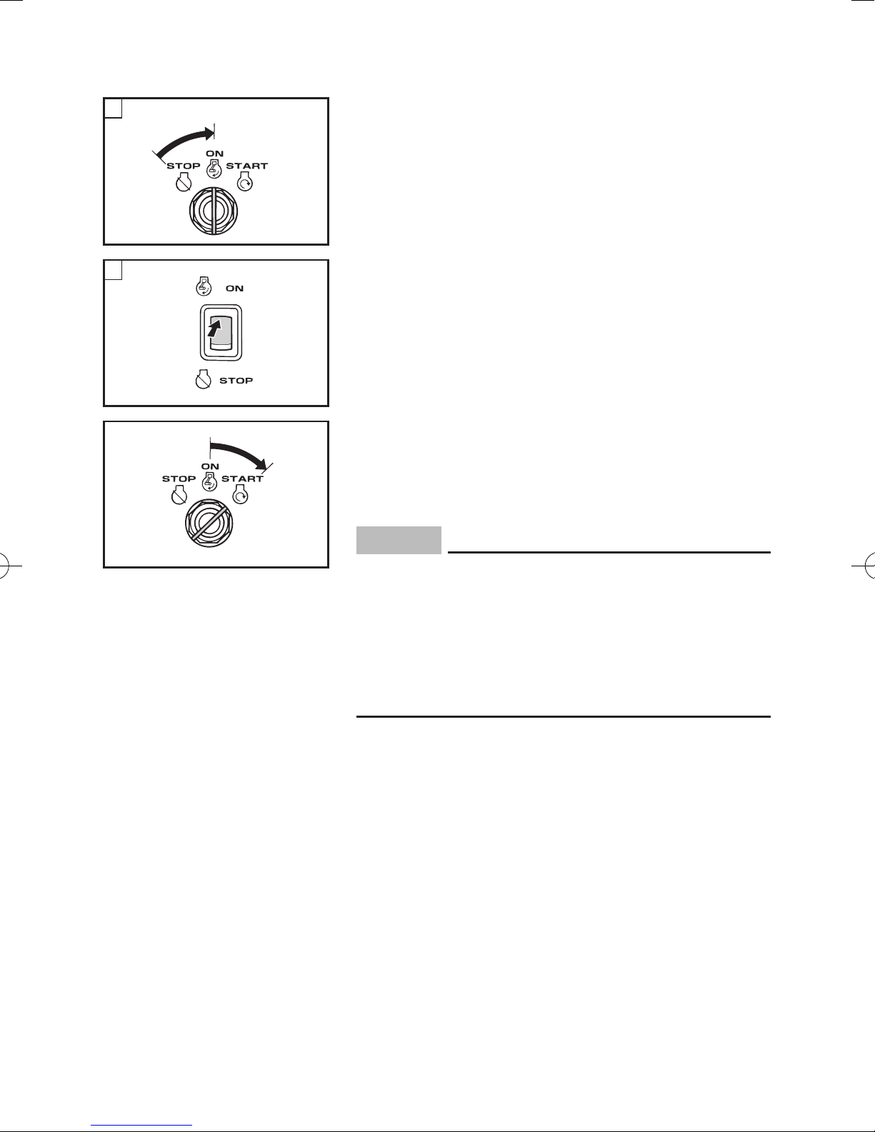
3. Turn the engine switch to “7” (ON).
3 “7” (ON)
å EF7200DE/EF7200E
∫ EF7200
Electric starting (Except for EF7200):
4
4. Turn the engine switch to “6” (START).
4 “6” (START)
763-120
NOTICE
9 Take your hand off the switch immediately
after the engine starts.
9 If the engine fails to start, release the switch,
wait a few seconds, then try again. Each
attempt should be as short as possible to pre-
serve the battery. Do not crank the engine
more than 5 seconds on any one attempt.
– 20 –
5
Manual starting:
4. Turn the choke lever to “1” (For EF7200).
5 Choke lever
TIP
The choke is not required to start a warm engine. Turn
the choke lever to the original position.
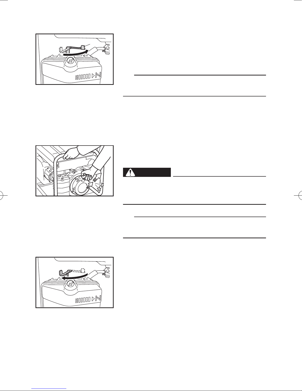
5. Pull the recoil starter slowly until it is engaged,
then pull it briskly.
WARNING
6
Be careful to use the recoil starter. In rare cases,
the recoil starter handle can be drawn back quickly
by the engine kickback.
TIP
Grasp the carrying handle firmly to prevent the generator from falling over when pulling the recoil starter.
6. After the engine starts, warm up the engine until
the engine does not stop when the choke lever is
returned to the original position (For EF7200).
6 Original position
– 21 –

Stopping the engine
1. Turn off any electric devices.
2. Turn the AC switch (N.F.B.) and economy control
switch to “3” (OFF).
1 “3” (OFF)
A
1
B
1
C
1
763-252b
å AC switch (N.F.B.) (EF7200DE)
∫ AC switch (N.F.B.) (EF7200/EF7200E)
ç Economy control switch (Except for EF7200)
1
3. Disconnect any electric devices.
– 22 –
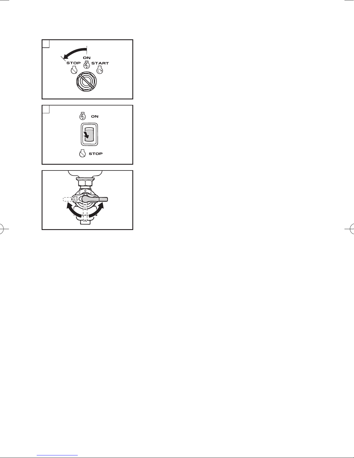
A
4. Turn the engine switch to “5” (STOP).
2
2 “5” (STOP)
å EF7200DE/EF7200E
∫ EF7200
763-130c
B
2
5. Turn the fuel cock lever to OFF.
3 OFF
33
705-038d
– 23 –
 Loading...