


OWNER’S MANUAL
Read this manual carefully before operating this machine.
Generator
EF5200DE
EF5200D
LIT-19626-01-76
7CB-F8199-13

Read this manual carefully before operating this machine.This manual should
stay with this machine if it is sold.

INTRODUCTION
Congratulations on your purchase of your new Yamaha.
This manual will provide you with a good basic understanding of the operation and
maintenance of this machine.
If you have any questions regarding the operation or maintenance of your machine,
please consult a Yamaha dealer.
EF5200DE/EF5200D
OWNER’S MANUAL
© 2011 by Yamaha Motor Corporation, U.S.A.
1st Edition, February 2011
All rights reserved.
Any reprinting or unauthorized use
without the written permission of
Yamaha Motor Corporation, U.S.A.
is expressly prohibited.
Printed in China
P/N LIT-19626-01-76
NOTICE
WARNING
WARNING
IMPORTANT MANUAL INFORMATION
Particularly important information is distinguished in this manual by the following
notations.
This is the safety alert symbol. It is
used to alert you to potential personal
injury hazards. Obey all safety messages that follow this symbol to avoid
possible injury or death.
A WARNING indicates a hazardous situation which, if not avoided, could
result in death or serious injury.
A NOTICE indicates special precautions that must be taken to avoid damage to the machine or other property.
TIP
A TIP provides key information to make
procedures easier or clearer.
PLEASE READ AND UNDERSTAND
THIS MANUAL COMPLETELY BEFORE
OPERATING THE MACHINE.
TIP
9 Yamaha continually seeks advance-
ments in product design and quality.
Therefore, while this manual contains
the most current product information
available at the time of printing, there
may be minor discrepancies between
your engine and this manual. If there
is any question concerning this manual, please consult a Yamaha dealer.
9 This manual should be considered a
permanent part of this engine and
should remain with this engine when
resold.
* Product and specifications are subject to
change without notice.

CONTENTS
SAFETY INFORMATION ........................1
Exhaust fumes are poisonous ..............1
Fuel is highly flammable and
poisonous .............................................2
Engine and muffler may be hot.............2
Electric shock prevention......................3
Connection notes..................................4
Connection ...........................................4
Extension cord notes ............................4
LOCATION OF IMPORTANT LABELS ..5
DESCRIPTION ........................................6
Control panel ........................................7
CONTROL FUNCTION............................8
Engine switch .......................................8
Oil warning light (red) ...........................8
AC switch (N.F.B.) ................................9
Economy control switch......................10
Voltage adjuster..................................10
G.F.C.I. receptacle .............................11
Fuel tank cap ......................................12
Fuel cock lever ...................................12
Ground (earth) terminal ......................12
PREPARATION.....................................13
Fuel.....................................................13
Engine oil............................................14
Battery installation ..............................15
PRE-OPERATION CHECK ...................17
Pre-operation check ...........................17
OPERATION..........................................18
Starting the engine .............................18
Stopping the engine............................21
Connection .........................................22
Application range................................24
PERIODIC MAINTENANCE ..................25
Maintenance chart ..............................25
Spark plug inspection .........................27
Carburetor adjustment........................28
Engine oil replacement .......................28
Air filter ...............................................30
Muffler screen and spark arrester.......31
Fuel cock ............................................33
Fuel tank filter .....................................34
Battery ................................................35
Recommended battery .......................36
Fuse replacement...............................36
G.F.C.I. receptacle test.......................37
STORAGE .............................................38
Drain the fuel ......................................38
Engine ................................................39
Battery ................................................40
TROUBLESHOOTING ..........................41
SPECIFICATIONS.................................46
Dimensions.........................................46
Engine ................................................46
Generator ...........................................46
Battery ................................................46
CONSUMER INFORMATION................47
Identification number records .............47
Machine identification .........................47
EXHAUST EMISSION CONTROL
SYSTEM AND COMPONENTS.............48
WIRING DIAGRAM ...............................49
EF5200DE ..........................................49
EF5200D ............................................50
BATTERY TRAY INSTALLATION........51
ENGINE HANGER INSTALLATION .....51
OPTIONAL PARTS INSTALLATION....52
YAMAHA MOTOR CORPORATION,
U.S.A.
EF SERIES GENERATORS
3-YEAR LIMITED WARRANTY............53
YAMAHA OUTDOOR POWER
EQUIPMENT
CALIFORNIA EVAPORATIVE
EMISSION CONTROL
WARRANTY STATEMENT ..................56
YAMAHA MOTOR CORPORATION,
U.S.A.
SMALL OFF ROAD ENGINES
CALIFORNIA EMISSION
CONTROL WARRANTY.......................57
YAMAHA EXTENDED SERVICE
(Y.E.S.)..................................................61
741-002
SAFETY INFORMATION
7CC-002
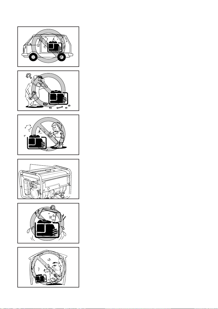
9 This generator is not designed for on-board use.
Do not use it while installed on the vehicle.
9 Do not modify the generator or use it with its parts
removed.
9 Do not allow children to operate the generator.
1
9 Be sure to carry the generator only by its carrying
handle(s).
1 Carrying handle(s) (shaded)
741-060c
9 Do not place any obstacles on the generator.
Exhaust fumes are poisonous
9 Never operate the engine in a closed area or it
may cause unconsciousness and death within a
short time. Operate the engine in a well ventilated
area.
– 1 –
741-003
741-005
741-007
741-008a
a
741-004
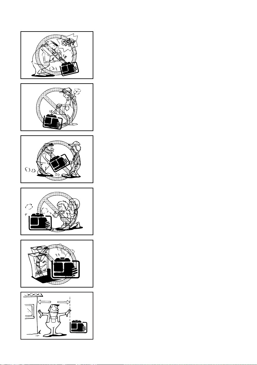
Fuel is highly flammable and poisonous
9 Always turn off the engine when refuelling.
9 Never refuel while smoking or in the vicinity of an
open flame.
9 Take care not to spill any fuel on the engine or
muffler when refuelling.
9 Do not leave the generator inside the vehicle or in
the trunk.
9 If you swallow any fuel, inhale fuel vapor, or allow
any to get in your eye(s), see your doctor immediately. If any fuel spills on your skin or clothing,
immediately wash with soap and water and
change your clothes.
9 When operating or transporting the generator, be
sure it is kept upright. If it tilts, fuel may leak from
the carburetor or fuel tank.
Engine and muffler may be hot
9 Place the generator in a place where pedestrians
or children are not likely to touch the generator.
741- 006
9 Avoid placing any flammable materials near the
exhaust outlet during operation.
9 Keep the generator at least 1 m (3 ft) from build-
ings or other equipment, or the engine may overheat.
a 1 m (3 ft)
– 2 –

741-010
741-011
7CC-001
1
741-128
9 Do not operate the engine with a dust cover or
other objects covering it.
9 When covering the generator, be sure to do so
only after the engine and muffler have completely
cooled down.
Electric shock prevention
9 Never operate the engine in rain or snow.
9 Never touch the generator with wet hands or elec-
trical shock will occur.
9 Connect the ground lead of the generator to the
ground (earth) terminal and connect the end to the
ground electrode buried in the ground.
1 Ground (earth) terminal
– 3 –

741-040a
1
2
1
2
Connection notes
WARNING
9 Avoid connecting the generator to commercial
power outlet.
9 Avoid connecting the generator in parallel with any
other generator.
1 Correct
2 Incorrect
Connection
Before the generator can be connected to a building’s electrical system, a licensed electrician must
install an isolation (transfer) switch in the building’s main fuse box. The switch is the connection
point for generator power and allows selection of
generator or main line power to the building. This
will prevent the generator from charging the main
power line (backfeeding) when the main power
supply has failed or has been turned off for line
repair. Backfeeding can electrocute or injure line
maintenance personnel. Also, generator and building electrical system damage can occur when normal operating power returns if unit is used without
an isolation switch.
Extension cord notes
Extension cords should be protected by a tough flexible rubber sheath (IEC 245) or the equivalent to withstand mechanical stresses.
– 4 –
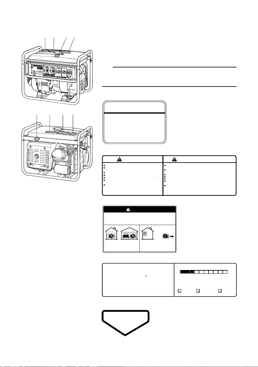
LOCATION OF IMPORTANT LABELS
1
2
3
4
5
4
2
1
Electrocution or property damage
can occur: Do not connect this
generator to any building’s electrical
system unless an isolation switch
has been installed by a licensed electrician. Refer to the owner’s manual.
7DF-F415A-00
WARNING
q
HOT EXHAUST
WARNING
7DF-F4162-10
AVERTISSEMENT
Read the owner’s manual and all labels before operating.
Check for spilled fuel or fuel leaks.
Stop engine before refueling.
Do not Operate near flammable materials.
Electrocution can occur if generator is used in rain,
snow, or near water, keep this unit dry at all times.
When operating the generator:
Never place a partition or other barrier around the generator.
Do not cover the generator with a box.
Do not place any objects on the generator.
Only operate in well-ventilated areas.
Exhaust gas contains poisonous carbon monoxide.
Lisez le mode d’emploi et toutes les etiquettes avant de
faire fonctionner la machine.
Verifiez si du carburant a ete renverse ou s’il fuit.
Arretez le moteur avant de faire le plein de carburant.
N’utilisez pas a proximite de materiaux inflammables.
Il y a risque d’electrocution si le generateur fonctionne sous la pluie, dans
la neige, ou pres de l’eau, gardez la machine ausec en toutes circonstances.
Quand la génératrice est en marche:
Ne jamais entourer la génératrice de cloisons ou d’écrans.
Ne jamais recouvrir la génératrice d’une boîte.
Ne jamais disposer d’objets sur la génératrice.
Faites fonctionner uniquement dans des lieux bien aeres.
Les gaz d’echappement contiennent du monoxyde de carbone.
The air index of this engine is 3
(California only)
MOST CLEAN LEAST CLEAN
0246810
Note: The lower the air index, the less the pollution.
This engine is certified to be emissions compliant
for the following use:
Check owner's manual for further details.
( *** HOURS) ( *** HOURS) ( *** HOURS)
MODERATE INTERMEDIATE EXTENDED
X
EMISSION CONTROL INFORMATION
YAMAHA MOTOR POWERED PRODUCTS CO.,LTD.
emission regulations for small off-road engines.
This engine meets 20** California exhaust and evaporative
THIS ENGINE MEETS U.S. EPA EXH EVP REGS FOR 20**.
EVAP F: ********
EF: ***********
EMISSION CONTROL SYSTEM: **
DISPLACEMENT: *** cc
EMISSION COMPLIANCE PERIOD : *** HOURS
This engine is certified to operate on unleaded gasoline.
No other adjustments needed.
ENGINE OIL: SAE***** TYPE : **
DANGER
Using a generator indoors CAN KILL YOU IN MINUTES.
Generator exhaust contains carbon monoxide.
This is a poison you cannot see or smell.
NEVER use inside a home
or garage, EVEN IF doors
and windows are open.
Only use OUTSIDE and
far away from windows,
door, and vents.
7CA-F4877-00
Please read the following labels carefully before operating this generator.
TIP
Maintain or replace safety and instruction labels, as
necessary.
1
2
3
4
5
– 5 –

EF5200DE
1
2
1
5
3
4
7
6
6
5
7
2
3114
w
q
0
1
98
1
e
w
0
q
9
1
r81
e
EF5200D
DESCRIPTION
1 Carrying handles (shaded)
2 Fuel tank cap
3 Fuel level gauge
4 Fuel tank
5 Ground (earth) terminal
6 Oil filler cap
7 Oil drain bolt
8 Spark plug
9 Voltage adjuster
0 Fuel cock
q Recoil starter
w Air filter case cover
e Muffler
r Choke lever (For EF5200D)
– 6 –

EF5200DE
8
834
5216
7
7
34 52167
Control panel
(For EF5200DE)
1 Starter switch
2 Economy control
switch
3 Engine switch
4 Oil warning light (red)
5 Voltage meter
6 G.F.C.I. receptacle
7 AC receptacle
8 AC switch (N.F.B.)
EF5200D
Control panel
(For EF5200D)
1 Engine switch
2 Economy control
switch
3 Oil warning light (red)
4 Voltage meter
5 G.F.C.I. receptacle
6 AC receptacle
7 AC switch (N.F.B.)
– 7 –

1
2
763-121
700-027c
CONTROL FUNCTION
Engine switch
The engine switch controls the ignition system.
1 7 “ON”
Ignition circuit is switched on.
The engine can be started.
2 5 “STOP”
Ignition circuit is switched off.
The engine will not run.
Oil warning light (red)
When the oil level falls below the lower level, the oil
warning light comes on and then the engine stops
automatically. Unless you refill with oil, the engine will
not start again.
TIP
If the engine stalls or does not start, turn the engine
switch to “ON” and then pull the recoil starter. If the oil
warning light flickers for a few seconds, the engine oil
is insufficient. Add oil and restart.
– 8 –
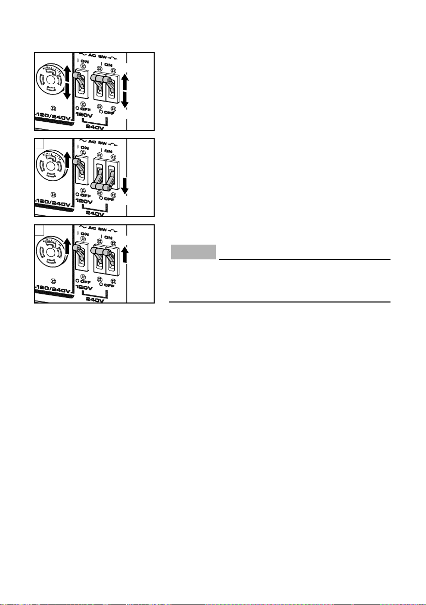
AC switch (N.F.B.)
1
2
1
2
NOTICE
The AC switch (Non-Fuse Breaker) turns off automatically when the load exceeds the generator rated output.
1 I “ON”
2 3 “OFF”
A
1
2
B
1
1
å Supplies AC 120 V
∫ Supplies AC 120 V and 240 V
Reduce the load to the specified generator rated
output if the AC switch (N.F.B.) turns off. If it turns
off again, consult a Yamaha dealer.
– 9 –

1
2
763-124
Economy control switch
240V
120V
120V
GR
779-017
W
X
G
Y
1 I “ON”
When the economy control switch is turned “ON”, the
economy control unit controls the engine speed
according to the connected load. The results are better
fuel consumption and less noise.
2 3 “OFF”
When the economy control switch is turned “OFF”, the
engine runs at the rated r/min (3,600 r/min) regardless
of whether is a load connected or not.
TIP
9 The economy control switch must be turned to
“OFF” when using electric devices that require a
large starting current, such as a compressor of a
submergible pump.
9 The economy control switch must be turned to
“OFF” to increase engine speed to rated rpm
when:
- using a load of 0.8 A or less.
- supplying AC 120 V only from W with Y.
Voltage adjuster
The voltage adjuster is equipped for adjusting output
voltage to rated voltage.
TIP
779-039
779-037
Turn the voltage adjuster clockwise or counterclockwise to increase or decrease output voltage.
– 10 –
1
2
763-083
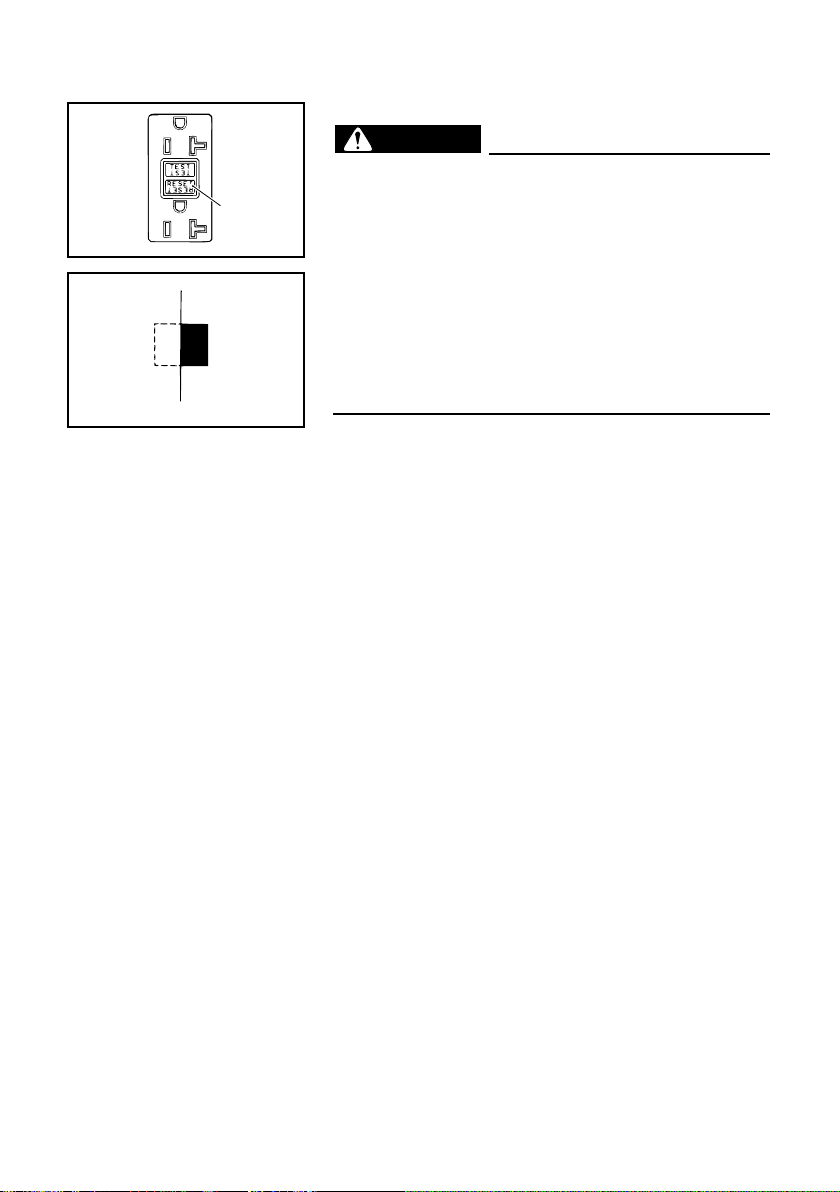
G.F.C.I. receptacle
WARNING
TO REDUCE THE CHANCE OF ELECTRICAL
SHOCK:
9 Do not attempt to operate electric devices if
the ground fault circuit interrupter reset button
pops out repeatedly during use.
3
763-060
9 Test the ground fault circuit interrupter during
the pre-operation checks according to the
maintenance instructions on page 37.
9 Remember that only receptacle labeled “GFCI”
have ground fault circuit interrupter protection.
The G.F.C.I. (Ground Fault Circuit Interrupter) shuts
off power to the protected receptacles if a ground fault
(electrical leak) is detected.
If the reset button pops out, the electric devices connected into the receptacle may be faulty. If this happens, check the electric devices carefully. If the electric devices appears to be in good condition, press the
reset button firmly until a click is heard. This will
restore power. If the reset button pops out again, disconnect all the electric devices immediately. Have the
electric devices inspected and repaired by a qualified
repairperson before attempting to use them again.
1 G.F.C.I. (Ground Fault Circuit Interrupter)
2 Reset button
3 Pops out
– 11 –

707-051a
Fuel tank cap
7DF-106
1
2
Remove the fuel tank cap by turning it counterclockwise.
Fuel cock lever
The fuel cock supplies fuel from the fuel tank to the
carburetor.
The fuel cock has two positions.
1 “ON”
With the lever in this position, fuel flows to the carburetor. Normal using is done with the lever in this position.
2 “OFF”
With the lever in this position, fuel will not flow. Always
turn the lever to this position when the engine is not
running.
Ground (earth) terminal
Ground (earth) terminal connects the earth line for pre-
1
vention of electric shock.
When the electric device is earthed, always the generator must be earthed.
741-128
1 Ground (earth) terminal
– 12 –

741-001
707-001
NOTICE
WARNING
707-051
PREPARATION
Fuel
9 Fuel is highly flammable and poisonous.
Check “SAFETY INFORMATION” (See page 2)
carefully before filling.
9 Do not overfill the fuel tank, otherwise it may
overflow when the fuel warms up and
expands.
9 After fill the fuel, make sure the fuel tank cap is
tightened securely.
9 Immediately wipe off spilled fuel with a clean,
dry, soft cloth, since fuel may deteriorate
painted surfaces or plastic parts.
9 Use only unleaded gasoline. The use of leaded
gasoline will cause severe damage to internal
engine parts.
Make sure there is sufficient fuel in the tank.
When refueling, be sure to fill the tank to the bottom
edge of the fuel filter.
1 Fuel level gauge
1
32
707-033a
7DF-020
2
“F” Full
3
“E” Empty
4 Fuel level
5 Fuel filter
Recommended fuel:
Unleaded gasoline
Fuel tank capacity:
4
5
Total:
23.0 L (6.08 US gal, 5.06 Imp gal)
Your Yamaha engine has been designed to use regular unleaded gasoline with a pump octane number ((R
+ M)/2) of 86 or higher, or research octane number of
91 or higher.
– 13 –

700-068
1
Engine oil
NOTICE
The generator has been shipped without engine
oil. Do not start the engine till fill with the sufficient engine oil.
1. Place the generator on a level surface.
2. Remove the oil filler cap.
1 Oil filler cap
0°C
å
YAMALUBE 4 (10W-40)
∂
SAE 10Wç SAE #20∫ SAE #30
32°F
25°C
80°F
700-006
2
700-110
3. Fill the specified amount of the recommended
engine oil, and then install and tighten the oil filler
cap.
2 Upper level
Recommended engine oil:
å YAMALUBE 4 (10W-40),
SAE 10W-30 or 10W-40
∫ SAE #30
ç SAE #20
∂ SAE 10W
Recommended engine oil grade:
API Service SE type or higher
Engine oil quantity:
1.1 L (1.16 US qt, 0.97 Imp qt)
– 14 –

830-002a
Battery installation (For EF5200DE)
WARNING
762-002
(See page 35 and 40 for more details)
9 Electrolyte is poisonous and dangerous since
it contains sulfuric acid, which causes severe
burns. Avoid any contact with skin, eyes or
clothing and always shield your eyes when
working near batteries. In case of contact,
administer the following FIRST AID.
9 EXTERNAL: Flush with plenty of water.
9 INTERNAL: Drink large quantities of water or
milk and immediately call a physician.
9 EYES: Flush with water for 15 minutes and
seek prompt medical attention.
9 Batteries produce explosive hydrogen gas.
Therefore, keep sparks, flames, cigarettes,
etc., away from the battery and provide sufficient ventilation when charging it in an
enclosed space.
9 KEEP THIS AND ALL BATTERIES OUT OF THE
REACH OF CHILDREN.
762-012
1. Fill the battery with the electrolyte.
Refer to the instruction sheet included with the
electrolyte for filling instructions.
2. Turn the engine switch to “STOP” to prevent accidental short circuiting.
3. Install the battery on the battery mount tray
securely.
4. Connect the positive lead (red) to the positive (+)
battery terminal first, then the negative lead
(black) to the negative (–) battery terminal. Do not
reverse these positions.
– 15 –

9 Be sure to service battery leads to prevent arc-
WARNING
2
1
762-004
ing when the battery is not installed.
9 Disconnect the battery charging output lead.
Then insulate the generator side connector by
folding it back on itself and carefully wrapping
it with electrical tape to prevent electrical contact with ground (earth) or any other leads.
3
1
762-005
9 Remove the battery leads from the generator.
1 Connector
2 Battery leads
3 Electrical tape
– 16 –
 Loading...