

Page 1
GUITAR AMPLIFIER
GUITAR AMPLIFIER
Owner’s Manual
GUITAR AMPLIFIER
GUITAR AMPLIFIER HEAD
Mode d’emploi
Bedienungsanleitung
Manual del Usuario
Manuale di Istruzioni
SPEAKER ENCLOSURE
SPEAKER ENCLOSURE
Page 2
FCC INFORMATION (U.S.A.)
1. IMPORTANT NOTICE: DO NOT MODIFY THIS UNIT!
This product, when installed as indicated in the instructions
contained in this manual, meets FCC requirements. Modifications not expressly approved by Yamaha may void your authority, granted by the FCC, to use the product.
2. IMPORTANT: When connecting this product to accessories
and/or another product use only high quality shielded cables.
Cable/s supplied with this product MUST be used. Follow all
installation instructions. Failure to follow instructions could
void your FCC authorization to use this product in the USA.
3. NOTE: This product has been tested and found to comply
with the requirements listed in FCC Regulations, Part 15 for
Class “B” digital devices. Compliance with these requirements provides a reasonable level of assurance that your use
of this product in a residential environment will not result in
harmful interference with other electronic devices. This
equipment generates/uses radio frequencies and, if not installed and used according to the instructions found in the
users manual, may cause interference harmful to the operation of other electronic devices. Compliance with FCC regula-
* This applies only to products distributed by YAMAHA CORPORATION OF AMERICA.
tions does not guarantee that interference will not occur in all
installations. If this product is found to be the source of interference, which can be determined by turning the unit “OFF”
and “ON”, please try to eliminate the problem by using one of
the following measures:
Relocate either this product or the device that is being affected by the interference.
Utilize power outlets that are on different branch (circuit
breaker or fuse) circuits or install AC line filter/s.
In the case of radio or TV interference, relocate/reorient the
antenna. If the antenna lead-in is 300 ohm ribbon lead,
change the lead-in to co-axial type cable.
If these corrective measures do not produce satisfactory
results, please contact the local retailer authorized to distribute this type of product. If you can not locate the appropriate
retailer, please contact Yamaha Corporation of America,
Electronic Service Division, 6600 Orangethorpe Ave, Buena
Park, CA90620
The above statements apply ONLY to those products distributed by Yamaha Corporation of America or its subsidiaries.
CANADA
This Class B digital apparatus complies with Canadian ICES-003.
Cet appareil numérique de la classe B est conforme à la norme NMB-
003 du Canada.
• This applies only to products distributed by Yamaha Canada Music Ltd.
• Ceci ne s’applique qu’aux produits distribués par Yamaha Canada Musique Ltée.
ADVARSEL!
Lithiumbatteri—Eksplosionsfare ved fejlagtig håndtering.
Udskiftning må kun ske med batteri af samme fabrikat og
type. Levér det brugte batteri tilbage til leverandøren.
VARNING
Explosionsfara vid felaktigt batteribyte. Använd samma
batterityp eller en ekvivalent typ som rekommenderas av
apparattillverkaren. Kassera använt batteri enlight
fabrikantens instruktion.
VAROITUS
Paristo voi räjähtää, jos se on virheellisesti asennettu. Vaihda
paristo ainoastaan laitevalmistajan suosittelemaan tyyppiin.
Hävitä käytetty paristo valmistajan ohjeiden mukaisesti.
IMPORTANT NOTICE FOR THE UNITED KINGDOM
Connecting the Plug and Cord
WARNING: THIS APPARATUS MUST BE EARTHED
IMPORTANT. The wires in this mains lead are coloured in
accordance with the following code:
GREEN-AND-YELLOW : EARTH
BLUE : NEUTRAL
BROWN : LIVE
As the colours of the wires in the mains lead of this apparatus may not
correspond with the coloured markings identifying the terminals in your
plug proceed as follows:
The wire which is coloured GREEN-and-YELLOW must be connected
to the terminal in the plug which is marked by the letter E or by the
safety earth symbol or colored GREEN or GREEN-and-YELLOW.
The wire which is coloured BLUE must be connected to the terminal
which is marked with the letter N or coloured BLACK.
The wire which is coloured BROWN must be connected to the terminal
which is marked with the letter L or coloured RED.
NEDERLAND / NETHERLAND
• Dit apparaat bevat een lithium batterij voor geheugen back-up.
• This apparatus contains a lithium battery for memory back-up.
• Raadpleeg uw leverancier over de verwijdering van de batterij op
het moment dat u het apparaat ann het einde van de levensduur
afdankt of de volgende Yamaha Service Afdeiing:
Yamaha Music Nederland Service Afdeiing
Kanaalweg 18-G, 3526 KL UTRECHT
Tel. 030-2828425
• For the removal of the battery at the moment of the disposal at the
end of the service life please consult your retailer or Yamaha
Service Center as follows:
Yamaha Music Nederland Service Center
Address : Kanaalweg 18-G, 3526 KL UTRECHT
Tel : 030-2828425
• Gooi de batterij niet weg, maar lever hem in als KCA.
• Do not throw away the battery. Instead, hand it in as small chemical
waste.
The exclamation point within the equilateral
triangle is intended to alert the user to the
presence of important operating and maintenance (servicing) instructions in the literature
accompanying the product.
The lightning flash with arrowhead symbol,
within the equilateral triangle, is intended to
alert the user to the presence of uninsulated
“dangerous voltage” within the product’s
enclosure that may be of sufficient magnitude
to constitute a risk of electrical shock.
• This applies only to products distributed by Yamaha-Kemble Music (U.K.) Ltd.
Page 3

IMPORTANT SAFETY INSTRUCTIONS
INFORMATION RELATING TO PERSONAL INJURY, ELECTRICAL SHOCK,
AND FIRE HAZARD POSSIBILITIES HAS BEEN INCLUDED IN THIS LIST.
WARNING- When using any electrical or electronic prod-
uct, basic precautions should always be followed. These precautions include, but are not limited to, the following:
1. Read all Safety Instructions, Installation Instructions,
Special Message Section items, and any Assembly Instructions
found in this manual BEFORE making any connections, including connection to the main supply.
2. Do not attempt to service this product beyond that de-
scribed in the user-maintenance instructions. All other servicing
should be referred to qualified service personnel.
3. Main Power Supply Verification: Yamaha products are
manufactured specifically for the supply voltage in the area
where they are to be sold. If you should move, or if any doubt
exists about the supply voltage in your area, please contact your
dealer for supply voltage verification and (if applicable) instructions. The required supply voltage is printed on the name plate.
For name plate location, please refer to the graphic found in the
Special Message Section of this manual.
4. DANGER-Grounding Instructions: This product must be
grounded and therefore has been equipped with a three pin attachment plug. If this product should malfunction, the ground
pin provides a path of low resistance for electrical current, reducing the risk of electrical shock. If your wall socket will not
accommodate this type plug, contact an electrician to have the
outlet replaced in accordance with local electrical codes. Do
NOT modify the plug or change the plug to a different type!
8. This product was NOT designed for use in wet/damp loca-
tions and should not be used near water or exposed to rain. Examples of wet /damp locations are; near a swimming pool, spa, tub,
sink, or wet basement.
9. This product should be used only with the components
supplied or; a cart ,rack, or stand that is recommended by the
manufacturer. If a cart, rack, or stand is used, please observe all
safety markings and instructions that accompany the accessory
product.
10. The power supply cord (plug) should be disconnected from
the outlet when electronic products are to be left unused for extended periods of time. Cords should also be disconnected when
there is a high probability of lightening and/or electrical storm
activity.
11. Care should be taken that objects do not fall and liquids are
not spilled into the enclosure through any openings that may exist.
12. Electrical/electronic products should be serviced by a
qualified service person when:
a. The power supply cord has been damaged; or
b. Objects have fallen, been inserted, or liquids have been
spilled into the enclosure through openings; or
c. The product has been exposed to rain; or
d. The product does not operate, exhibits a marked change
in performance; or
e. The product has been dropped, or the enclosure of the
product has been damaged.
5. WARNING: Do not place this product or any other
objects on the power cord or place it in a position where anyone
could walk on, trip over, or roll anything over power or connecting cords of any kind. The use of an extension cord is not recommended! If you must use an extension cord, the minimum
wire size for a 25' cord (or less) is 18 AWG. NOTE: The smaller
the AWG number, the larger the current handling capacity. For
longer extension cords, consult a local electrician.
6. Ventilation: Electronic products, unless specifically
designed for enclosed installations, should be placed in locations
that do not interfere with proper ventilation. If instructions for
enclosed installations are not provided, it must be assumed that
unobstructed ventilation is required.
7. Temperature considerations: Electronic products should
be installed in locations that do not seriously contribute to their
operating temperature. Placement of this product close to heat
sources such as; radiators, heat registers etc., should be avoided.
PLEASE KEEP THIS MANUAL
92-469-3
13. This product, either alone or in combination with an ampli-
fier and headphones or speaker/s, may be capable of producing
sound levels that could cause permanent hearing loss. DO NOT
operate for a long period of time at a high volume level or at a
level that is uncomfortable. If you experience any hearing loss or
ringing in the ears, you should consult an audiologist.
IMPORTANT: The louder the sound, the shorter the time period
before damage occurs.
14. Some Yamaha products may have benches and/or acces-
sory mounting fixtures that are either supplied as a part of the
product or as optional accessories. Some of these items are designed to be dealer assembled or installed. Please make sure that
benches are stable and any optional fixtures (where applicable) are
well secured BEFORE using. Benches supplied by Yamaha are
designed for seating only. No other uses are recommended.
Page 4

Thank you for purchasing a Yamaha DG Series Guitar Amplifier.
The DG Series Digital Guitar Amplifiers were initially conceiv ed and entirely developed by Yamaha.
These digital guitar amps deliver powerful tube amp sounds and off er superior stability compared to
other tube amplifiers. With eight different amp type settings from which to choose, the DG Series
Guitar Amplifiers allow you to create a wide variety of original sounds. A total of 128 sound settings
can be stored in their internal memory and freely recalled using the panel buttons or a MIDI foot
controller. Also, the DG Series Guitar Amplifiers are equipped with four on-board digital effects
(reverb, tremolo, chorus and tape echo) that can be utilized to add sonic color to your tonal creations, and a speaker simulator to add realistic speaker simulation to the line out signal. Its high
level of quality and easy to use controls will enable you to create a wide variety of tonal colors.
The S412V enclosure is equipped with four 30 cm Celestion “Vintag e 30” speakers and has a pow er
rating of 240 watts.
The S112 enclosure is equipped with a 30 cm Celestion “G12H-100” speaker and has a power
rating of 100 watts.
To get the best results and longest life out of your DG Series Guitar Amplifier, we recommend that
you carefully read this manual, and keep it in a safe place for future reference.
4
Page 5
DG100-212A/DG80-210A/DG80-112A/DG130HA
Precautions...................................................................5
The Panel Controls ...................................................... 6
■ Front Panel...................................................................... 6
■ Rear Panel ...................................................................... 7
Connecting Speakers .................................................. 8
■ For the DG100-212A....................................................... 8
■ For the DG80-210A/DG80-112A..................................... 8
■ For the DG130HA ........................................................... 8
How to use your DG Series Amplifier ........................ 9
■ First, achieve sound output ............................................. 9
■ Adjust the TRIM level ...................................................... 9
■ Sound Settings................................................................ 9
■ Reverb Settings............................................................... 9
■ Effect (Tremolo, Chorus, Tape Echo) Settings ................ 9
Recall and Store .........................................................10
■ Recall Memory (Recall) ................................................ 10
■ Store Settings ............................................................... 10
Easy to Use Functions...............................................11
■ Using MIDI to Recall Memory ....................................... 11
■ Using MIDI to Control Volume....................................... 11
■ Controlling Reverb, Tremolo, Chorus
and Tape Echo via MIDI......................................... 11
■ Speaker Simulator ........................................................ 11
Contents
Utility Mode................................................................. 12
■ Creating a Program Change Table................................ 12
■ Set the MIDI Receive Channel...................................... 12
■ Set the MIDI Merge....................................................... 12
■ MIDI Bulk Out................................................................ 12
■ MIDI Bulk In .................................................................. 12
■ MIDI Transmission/Reception between
DG series amplifiers. ................................................. 13
■ Speaker Simulator ON/OFF.......................................... 13
■ Set the Volume Pedal Position ...................................... 13
Error Messages ..........................................................14
Specifications............................................................. 15
MIDI Implementation Chart ....................................... 17
Patch List .................................................................... 18
S412V/S112
Using the S412V/S112................................................16
Precautions
● Avoid using your amplifier and speaker in the following locations
to prevent possible damage:
• In direct sunlight or next to heating equipment.
• Extremely cold or hot locations.
• Locations exposed to high humidity or excessive dust.
• Locations subject to strong shocks or vibration.
● Before making any connections, make sure that the power on
the amplifier and any external devices is switched OFF.
● To protect the speaker from possible damage, always set the
OUTPUT knob to “0” before switching the power ON/OFF.
● When connecting a speaker to this unit make sure to turn OFF
the power first.
● Do not apply excessive force to the switches and controls.
● Your Yamaha guitar amplifier is a precision musical instrument.
Handle it with care and avoid dropping or bumping it.
● Operating temperatures will rise during use. Make sure the
amplifier is used in a well-ventilated area. The DG130HA should
be placed in a position were there is at least 30 cm (12”)
clearance from the wall on the sides, top and back of the
amplifier.
● For safety, always remove the power plug from the AC wall
outlet if there is any danger of lightning striking in your area.
● Keep the amplifier away from neon signs or fluorescent lighting
to prevent noise pickup.
● To prevent damage and possibly electrical shock, never open
the case and tamper with the internal circuitry.
● Never use benzene, thinner or other volatile liquids for cleaning,
as these chemicals may cause damage or discoloration to the
finish. Always use a dry, soft cloth to wipe off dust and dirt.
About the Backup Battery
(DG series Guitar Amplifiers)
A backup battery (lithium battery) is used to keep internal data
(settings) from being lost, even when the power cord is unplugged.
Internal data will be lost when battery power is depleted, so it is
recommended that data be stored to an external data recorder
such as the Y amaha MIDI Data Filer MDF3 (→ page. 12), or keep
records of settings in memo form. The average battery life span is
about 3 years. When replacement becomes necessary contact
the music store where the unit was purchased, or a qualified service representative, to perform the replacement.
• Do not attempt to replace the backup battery by yourself.
• Keep the backup battery out of reach of children.
•“E6” appears in the display when the battery becomes depleted.
Internal data may be lost.
• Data may be lost if the unit is improperly handled or if repairs are
performed.
5
Page 6
DG100-212A/DG80-210A/DG80-112A/DG130HA
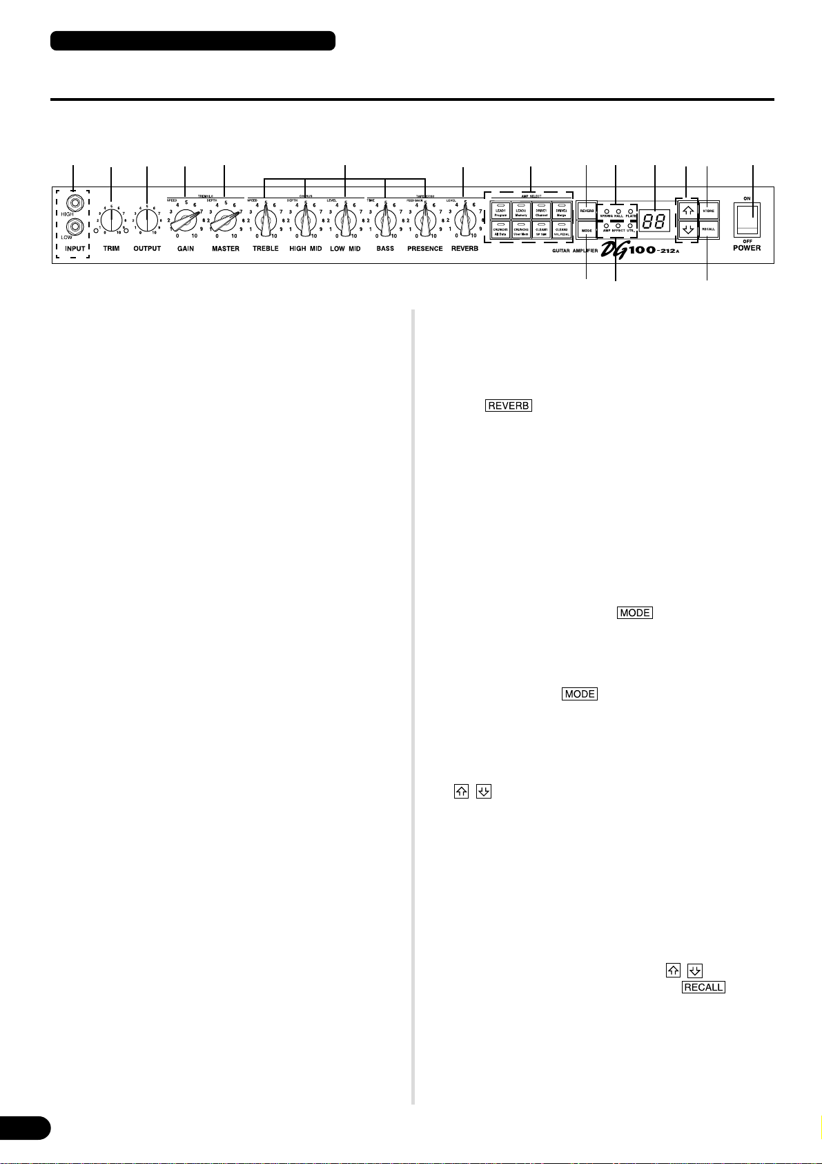
The Panel Controls
■ Front Panel
w e r t y uq i o !0 !3 !4 !5 !7
q Input Jack (INPUT HIGH, LOW)
Connect the guitar to this jack. Guitars with a high output level should be
connected to the LOW jack. Those with low output levels should be connected to the HIGH jack.
* Switch the power OFF before connecting the guitar.
w Trim Control (TRIM)
Used to match the guitar’s output level to the pre-amp’s input level. (→
page 9.)
* TRIM level settings are not stored in memory.
e Output Level Control (OUTPUT)
Used to control the output volume of the power amp.
Sets the amount of output of sound created by the preamp’s GAIN,
MASTER, Tone Controls, etc. The volume is controlled without changing the tonal quality of the amp.
* Output level settings are not stored in memory.
* Has no affect on the level (volume) of the LINE OUT @4 jack.
r Gain V olume (GAIN)
Used to control the amount of distortion.
* Sound is not produced if the GAIN is set to 0, even when the MASTER VOL-
UME t is turned up.
When the Effect Mode is engaged, the GAIN knob is used to adjust the
tremolo’s SPEED setting. (→ page 9.)
t Master V olume (MASTER)
Used to control the overall volume of GAIN and tone control settings. It
also controls the output level of the preamp.
* Master level settings are stored in memory.
When the Effect Mode is engaged, the MASTER knob is used to adjust
the tremolo’s DEPTH setting. (→ page 9.)
y Tone Controls
(TREBLE, HIGH MID, LO W MID, BASS, PRESENCE)
Used to control the levels of their respective frequencies.
When the effect mode is engaged, it is possible to make the following
adjustments; (→ page 9.)
• TREBLE, HIGH MID, LOW MID → chorus’ SPEED, DEPTH, LEVEL
• BASS, PRESENCE → tape echo’s TIME, FEED BACK
u Reverb V olume (REVERB)
Used to control the amount of the reverb. (→ page 9.)
When the Effect Mode is engaged, the REVERB knob is used to adjust
the tape echo’s LEVEL setting. (→ page 9.)
i Amp Select Button/Amp Select Display
(LEAD 1, 2/DRIVE 1, 2/CRUNCH 1, 2/CLEAN 1, 2)
Used to select one of the eight preset amp types. The currently selected amp type is shown on the display. (→ page 9.)
When the Utility Mode is engaged, these switches are used to switch
MIDI functions and the Speaker Simulator ON or OFF, etc. (→ page 12.)
* The DG100-212A is shown in the illustration.
!2!1 !6
* When the Amp Select button is pressed, knobs r – y r eturn to their preset
positions (GAIN and MASTER =7, Tone Controls all = 5). The position of
the REVERB knob does not change.
o Reverb Type Select Button (REVERB)
!0 Reverb T ype Display Lamp (SPRING, HALL, PLA TE)
Press the button to select the reverb type. The lamp corresponding to the selected reverb type will light. (→ page 9.)
!1 Mode Select Button (MODE)
!2 Mode Display Lamp (AMP/EFFECT/UTIL.)
Displays the currently selected mode.
• AMP (Amp Mode)
Normal playing mode. All knobs and buttons on the panel function as
marked. (Dual function knobs and buttons will function according to
their lower indications.)
This mode is automatically engaged whenever a memory is recalled.
• EFFECT (Effect Mode) → page 9
The Effect (tremolo, chorus, tape echo) setting mode.
When in the Amp Mode, press the button once and quickly
release to enter the Effect Mode.
• UTIL. (Utility Mode) → page 12
This mode is used to set MIDI functions, switch Speaker Simulation
ON or OFF and set Volume Pedal position. When in the Amp Mode or
Effect Mode, press the button and hold for about one second to enter the Utility Mode.
!3 Display
Displays Memory Numbers, Program Change Numbers, the MIDI Channel, etc.
!4 / Buttons
Increases or decreases the memory number by 1. Also, increases or
decreases values by 1. In the Utility Mode increases/decreases values
by 1 or sets the function ON/OFF . V alues change continuously when the
button is pressed and held.
!5 Store Button (STORE)
Press this button to save current sound settings to internal memory . (→
page 10.) Also, used to carry out MIDI Bulk Out operations. (→ page
12.)
!6 Recall Button (RECALL)
Recalls the settings stored in memory. Use the / buttons to select a memory number (01 – 128), then press the button to
recall those settings from memory. ( → page 10.)
!7 Power Switch (POWER)
The power switch for the amplifier.
* To protect the speakers from possible damage, always set the OUTPUT e
volume to “0” before turning the power ON/OFF.
6
Page 7

DG100-212A/DG80-210A/DG80-112A/DG130HA
The Panel Controls
■ Rear Panel
Before making any connections, make sure that the power on the DG amplifier and any external devices is switc hed OFF.
!8
On the DG100-212A, you can connect the internal
speaker or, an external speaker to the amplifier.
On the DG80-210A/DG80-112A, you can connect
the internal speaker or, an external speaker or , the
internal speaker plus an external speaker to the
amplifier.
On the DG130HA, connect speaker(s) to the amplifier.
!9
@0
MIDI IN
MIDI OUT
STATUS
BANK MSB/MAX
DATA/CTRL
BANK LSB/MIN
TOGGLE ON-OFF
8.8.8
/NUMBER OF PGM
@1
@3
OUT
External Effector
INC
MEMORY
WRITE
DEC
±10
.
/NO
/YES
EDITPCEDIT
/EXIT
@2 @4
IN
* The DG80-112A is shown in the illustration.
@5
Mixer or additional amp
A MIDI Controller can be used to
Store data from the DG amplifier’s
internal memory to a MIDI device.
select memory and control
volume.
!8 Speaker Jack (SPEAKER)
DG100-212A: The internal speaker is connected to the amp.
DG80-210A/DG80-112A: Equipped with 2 speaker jacks. The internal
speaker is connected to the SPEAKER 1 jack.
DG130HA: Equipped with 2 speaker jacks.
Refer to the “Connecting Speakers” section on page 8 for
instruction on the connection of speakers to the amp.
!9 MIDI OUT Jack
Connect this jack to the MIDI IN jack of a device that can save MIDI
data. The data stored in the DG amplifier’s internal memory can then be
transmitted to an external MIDI device for storage. (→ page 12: MIDI
Bulk Out)
Also, transmits MIDI data received by the MIDI IN jack @0, to an external
device when MIDI Merge is set to ON. (→ page 12.)
@0 MIDI IN Jack
Connect this jack to a MIDI Foot Controller’s MIDI OUT jack, and the
external foot controller can be used to control the DG amplifier. Memory
selection, volume control, effects can all be controlled via an external
foot controller. (→ page 11.)
Also, memory data stored in an external storage device can be re-loaded
into any DG amplifier’s internal memory. (→ page 12 MIDI Bulk In)
@1 Effect Blend Control (EFFECT BLEND)
@2 Effect Send Jack (EFFECT SEND)
@3 Effect Return Jack (EFFECT RETURN)
An external effector can be inserted into the signal circuit between the
SEND/RETURN jacks. This allows further processing of the tone signal,
created by the main unit, by an external effector . Use the BLEND knob
to control the balance level between the external effector’s sound (EFFECT) and the sound created by the DG amplifier (DRY). Rotating the
knob fully to the EFFECT position allows only the sound produced by
the external effector to be heard. Rotating the knob fully to the DRY
position allows only the internal sound created by the amp to be heard,
without the added coloration of the external effector.
* Connecting a plug to the RETURN jack disconnects the internal circuit. The
signal returning from the effector enters the internal circuit here, where it
goes on to the power amp → speaker. When the RETURN jack is not in use,
the BLEND knob will have no affect.
Also, the SEND jack can function as a pre-out jack, and the RETURN jack
can function as a main-in jack.
@4 Line Out Jack (LINE OUT)
@5 Line Out Level Control (LINE OUT LEVEL)
The same signal that is sent to the speaker output jack !8, is also sent
to the LINE OUT jack at a line level (+4 dBm / 600 Ω). The amp also has
an internal Speaker Simulator (can be switched ON/OFF → page 13.),
the output level can be controlled with the LINE OUT LEVEL knob. The
line signal can be sent to a mixer and can be used as an output jack to
an external amp.
7
Page 8

DG100-212A/DG80-210A/DG80-112A/DG130HA
Connecting Speakers
Before connecting speakers to the speaker jack(s) check the power rating and impedance of the speaker and make sure
they meet or are within the requirements recommended for the equipment.
■ For the DG100-212A
The amplifier’s internal speaker (4 Ω) is connected to the speaker jack.
If it is necessary, you can disconnect the internal speaker and connect
an external speaker to the speaker jack.
When an external speaker is used, make sure the speaker(s) meets the
following requirements.
• A power rating of at least 100 W, impedance of 4 – 8 Ω.
■ For the DG80-210A/DG80-112A
The amp’s internal speaker (8 Ω) is connected to the SPEAKER 1 jack.
The SPEAKER 2 (EXT) jack can be used to add an external speaker(s).
Also, if necessary, you can disconnect the internal speaker to connect 2
external speakers directly to the amp. The two speaker jacks are connected in parallel. When external speakers are used, make sure the
speakers meet the following requirements.
Total Impedance
If two or more speakers are to be connected, you must take into
consideration the total impedance of the speakers.
Speakers normally have an impedance of 4, 8 or 16 Ω. When two
or more speakers are used together, the total impedance will
change according to the manner in which the speakers are connected.
● Connecting in a series
The total impedance equals the impedance of the 1st speaker +
2nd speaker + 3rd speaker + …
When three speakers are connected in a series, as shown below, the total impedance will be 24 Ω.
● When one speaker jack is used.
• A power rating of at least 100 W, impedance of 4 – 16 Ω.
• The total impedance for the speakers in a circuit must not be less
than 4 Ω.
● When both speaker jacks are used.
• Speakers connected to each jack must have a power rating of at
least 100 W, and impedance of 8 – 16 Ω.
• The total impedance for the speakers in a circuit must not be less
than 4 Ω.
■ For the DG130HA
The amp is equipped with two speaker jacks. The two speaker jacks are
connected in parallel. Make sure the speakers meet the following requirements.
● When one speaker jack is used.
• Power rating of at least 130 W, impedance of 4 – 16 Ω.
• The total impedance for the speakers in a circuit must not be less
than 4 Ω.
● When both speaker jacks are used.
• Speakers connected to each jack must have a power rating of at
least 100 W, and impedance of 8 – 16 Ω.
• The total impedance for the speakers in a circuit must not be less
than 4 Ω.
● Connecting in a parallel series
The total impedance =
When three speakers are connected in a parallel series, as shown
below, the total impedance will be about 2.7 Ω.
For the DG80-210A/DG80-112A
The two speaker jacks are connected in a parallel circuit internally therefore, adding a 4 Ω external speaker to the 8 Ω internal
speaker results in a total impedance of 2 Ω. In order to maintain a
minimum impedance of 4 Ω, an 8 Ω speaker or greater must be
used as an external speaker.
Internal Speaker 8 Ω
External Speaker
Greater that 8 Ω
8
Page 9

DG100-212A/DG80-210A/DG80-112A/DG130HA
How to use your DG Series Amplifier
T o protect the speaker from possible damage, always set the OUTPUT knob to “0”
before switching the power ON/OFF.
■ First, achieve sound output
1. With the DG amplifier’s power switched OFF, connect y our guitar to the INPUT jack on the front panel. To start with, try using
the LOW jack.
2. With the OUTPUT knob set to “0”, switch the power ON.
3. As a starting point, set the TRIM le vel to “5” and strum the guitar. Then, gradually raise the OUTPUT level.
4. Once you have sound output, proceed to set the TRIM level as
described in the following section.
■ Adjust the TRIM level
The TRIM level allows you to set the output level of the guitar to an
optimum level that matches the DG amplifier’s INPUT jack. With a well
adjusted TRIM level, subtle picking nuances and the attack of a strong
strum can be clearly heard. An improperly adjusted trim level will result
in noise, feedback, and/or a cut up sound.
* The output level between guitars does vary. Whenever you switc h guitars, it
will be necessary to readjust the trim level to match the guitar.
* HIGH and LOW input levels are different. Even if the same guitar is used,
make sure the TRIM level is readjusted whenever a different input jack is
used.
* Even when creating distortion, make sure that the TRIM level is properly
adjusted, and use the GAIN control to produce distortion.
1. Set the guitar’s volume to its maximum level and powerfully
strum the guitar. Begin to adjust the TRIM level.
An optimum level is achieved when the Green LED is lit.
2. Continue rotating the TRIM knob to the right, so long as the
Red LED does not light. Set the TRIM level to “10” if the Red
LED does not light.
* If the Red LED still does not light, lower the TRIM level, connect the
guitar to the HIGH input jack and repeat the previous procedure.
■ Sound Settings
Choose one of the DG amplifier’s eight preset amp types, then use the
GAIN+MASTER, and tone controls to shape the guitar’s sound.
1. Choose an amp type using one of the AMP SELECT buttons.
The selected amp type button’s LED will light.
2. Use the GAIN, MASTER, and the five tone controls to shape the
guitar’s sound.
HINT OUTPUT knob and MASTER knob
Turning either knob will change the volume. The MASTER knob
controls the preamp’s master volume. This setting is stored in
memory. The OUTPUT knob controls the power amp’s volume.
This setting is not stored in memory. Volume levels for individual
memory settings should be set with the MASTER knob. The
speaker’s output level should be controlled with the OUTPUT knob.
* When an AMP SELECT button is pressed, all knobs (except TRIM,
OUTPUT and REVERB) will return to their preset positions. (GAIN
and MASTER = 7, all tone controls = 5. To save edited settings, refer to
the “Store Settings” section on page 10.)
■ Reverb Settings
1. Press the REVERB button to select a reverb type. Each time
the REVERB button is pressed, the type will cycle through
SPRING → HALL → PLATE settings. The lamp for the selected
reverb type will light.
2. Use the REVERB knob to adjust the amount of reverb.
* Reverb settings (type and REVERB knob settings) will remain in affect,
even if the AMP SELECT button is pr essed to change the amp type . When a
different memory number is recalled, the reverb settings for that memory
number will then be in affect.
■
Effect (Tremolo, Chorus, Tape Echo) Settings
1. Press the button so that the EFFECT lamp is lit.
When the EFFECT mode is entered each knob, GAIN — REVERB, will rotate to the positions set in the memory.
2. Use the GAIN — REVERB knobs to adjust the amount of each
effect as needed.
● Tremolo Effect
• GAIN (SPEED: Tremolo Speed)
Sets the speed of the Tremolo Effect (the speed at which the effect’s
volume is increased and decreased). Rotate the knob to the right to increase the speed.
• MASTER (DEPTH: Tremolo Depth)
Sets the depth of the Tremolo Effect (the upper and lower limits of the
effect’s volume). Rotate the knob to the right to produce more effect.
● Chorus Effect
• TREBLE (SPEED: Chorus Speed)
Sets the speed of the Chorus Effect (the speed at which the effect’s pitch
is raised and lowered). Rotate the knob to the right to increase the speed.
• HIGH MID (DEPTH: Chorus Depth)
Sets the depth of the Chorus Effect (the upper and lower limits of the
effect’s pitch). Rotate the knob to the right to produce more effect.
• LOW MID (LEVEL: Chorus Level)
Sets the mix level of the Chorus Effect.
● Tape Echo Effect
• BASS (TIME: Echo Time)
Sets the amount of time between the sounding of the string and the echo
sound (the amount of time it takes between one echo and the next).
Rotate the knob to the right to increase the amount of time.
• PRESENCE (FEEDBACK)
Sets the length of time that the echo will repeat. Rotate the knob to the
right to increase the length of time. Rotating the knob too much can result in uncontrollable feedback, please use caution.
• REVERB (LEVEL: Echo Level)
Sets the echo’s volume level.
3. When the setting procedure is complete, press the or
button and the AMP lamp will light.
Each of the GAIN — REVERB knobs will revert to the positions
they were to prior to entering the EFFECT mode.
* Effect settings will remain in effect even if the AMP SELECT button is pressed
to select another amp type. When you recall a different memory number
with the “Recall Memory” function (refer to page 10), the settings for that
memory number’s effect will then be in affect.
With the procedures on this page, you can create an
original sound (settings), and along with the reverb
and effect settings they can be stored in the DG
amplifier’s internal memory for instant recall at anytime. The procedure for storing data in memory is explained on the next page.
9
Page 10

DG100-212A/DG80-210A/DG80-112A/DG130HA
Recall and Store
Preset setting data, specially created by Y amaha for the DG Series Amplifiers, is installed in memory numbers 1-80 when the amplifier is shipped from
the factory. (Refer to the “Patch List” on page 83.)
Setting data contains Amp T ype and its settings (GAIN, MASTER, Tone Control, Reverb, T remolo, Chorus and Tape Echo) that you can recall freely and
use at any time. Motor drives in the knobs will automatically set the knobs to the corresponding positions. Also, any settings that you create can be saved
(store) to any of the memory numbers 1 – 128. After creating a favorite sound, try saving it.
■ Recall Memory (Recall)
Sound settings stored in memory can easily be recalled by selecting a
memory number.
When a memory is recalled, the current settings will be
changed. If you want to keep the settings, use the Store operation, described on the right side of this page, to store settings to memory.
1. Press the button, the AMP or EFFECT mode display
will light.
2. Use the / buttons to select the memory number you
want to recall. The memory number will appear on the display
(flashing).
3. Press the button. The flashing memory number will
light. Each of the knobs, and the Amp Select Display will change
according to the data recalled from memory.
* Settings will not change until the button is pushed.
* TRIM and OUTPUT knob settings will not change with the Recall op-
eration.
* It takes anyw here from 1 – 10 seconds for the knobs to change to their
set positions however, internal settings (sound) will change instantly.
*“E1” will appear on the display if the volume knob does not go to its
assigned position, or the device does not recognize the recall command
after 20 seconds has elapsed from the start of the recall oper ation. Continued use of the device in this condition may result in fire or electrical
shock. T ake the unit to the music dealer w here you pur chased it, or to the
nearest Yamaha Service Center for repair.
The memory number to be recalled, shown on
the display, goes from flashing to lit.
■ Store Settings
1. Use the procedure on page 9 and create a sound using the
eight preset amp types and control knobs on the front panel.
* Each of the Utility Mode’s settings cannot be stor ed in individual memory .
When the power is switched OFF, each memory’s settings are stored in
memory as common settings. When the power is turned ON, those settings are recalled.
2. Press the button, the AMP or EFFECT mode display
lamp will light.
3. Using the / buttons, select a memory number to which
the settings will be saved. The memory number will flash in the
display.
* Press and hold either of the / buttons makes memory numbers
cycle rapidly.
* The third digit of the memory number (100 – 128) is represented by a dot
between the two digits.
Example) 128 is displayed as →
4. Press and hold the b utton for about one second, until
“8.8” appears on the display.
Release the button, the flashing memory number will then light
indicating the setting is saved to memory.
* TRIM and OUTPUT settings cannot be stored in memory. Use the MAS-
TER knob to set backing and soloing levels.
The memory number to be stored.
Flashing → 8.8. → Lights
Execute Store
10
Lights
Select the memory number to be recalled.
A MIDI foot controller or other external MIDI device can
be used to select and recall memory. Refer to the following page to page 13 for details.
Execute Recall
Initialize the memory
While holding both the button and button,
turn the Power Switch ON, the initialize to factory preset operation will be carried out and the entire memory will be returned to
its factory preset condition.
When the initialize operation is carried out, data in memory numbers 1-80 will be re-written with data in the Patch List and the
data in memory numbers 81 – 128 will also be reset to their factory preset condition. Any data you have saved to memory will be
erased, so we strongly recommend that you save any important
data to an external MIDI device or document the settings before
carrying out the operation.
Lights
Data stored in memory (1 – 128) can be saved to an external MIDI storage device. Refer to page 12 for details.
Select the memory number.
HINT Some hints on storing memory numbers
When storing data to memory numbers, divide the memory numbers 1 – 128 into several groups.
Recalling memory numbers from these groups is much more convenient. For example:
•
Create groups according to the amp type used (LEAD1, DRIVE 1, etc.).
• Create groups based on sound types (Distortion, Clean, etc.)
• Create groups based on live performance song lists.
• Create groups based on the type of guitar used (humbucker, etc.).
It is also a good idea to keep a chart handy listing the types of
sounds are stored in memory numbers.
Page 11

DG100-212A/DG80-210A/DG80-112A/DG130HA
Easy to Use Functions
MIDI commands can be used to select memory numbers, control the reverb, tremolo, chorus and tape echo effects, and control
volume on the DG amplifier. A speaker simulator can also be applied to the LINE OUT signal.
What is MIDI? MIDI is the acronym for Musical Instruments Digital Interface. MIDI is a world-wide standard communication interface
that allows MIDI compatible musical instruments, computers and other MIDI devices to share musical information and
control one another regardless of instrument type or maker.
■ Using MIDI to Recall Memory
Program changes sent from a Y amaha MIDI Foot Controller MFC10, etc., or
an external MIDI device can be used to recall settings in the DG amplifier’s
memory.
1. With a MIDI cable, connect the DG amplifier’s MIDI IN jack to the
MIDI OUT jack on an external MIDI device.
* Use only a standard MIDI cable that is less than 15 meters in length. Use of a
longer cable may result in abnormal operation.
MIDI Cable
DG amplifier
Rear Panel
MIDI IN
STATUS
BANK MSB/MAX
DATA/CTRL
BANK LSB/MIN
TOGGLE ON-OFF
/NUMBER OF PGM
MIDI OUT
DEC
INC
MEMORY
±10
8.8.8
.
/NO
/YES
EDITPCEDIT
WRITE
/EXIT
1. Using procedures 1. and 2. in the previous “MIDI Memory Recall”
section, connect the external MIDI device and set the MIDI receive
channel.
2. Next, select the volume control position.
→ For instructions on the setting procedure, refer to page 13 “Set the
Volume Pedal Position”.
3. In this condition, number 7 control change data transmitted from
an external MIDI device will now control the DG amplifier’s volume.
* The DG amplifier does not except MIDI control changes other than numbers
7 and 91 to 94.
* For more information on transmitting control data, refer to your external
MIDI device’s owner’s manual.
* Even if another memory number is selected, main volume data will not change.
* When the power is switched ON, main volume data is set to its maximum
level.
* After the main volume data is changed, and the external MIDI device is
disconnected, the volume level may be insufficient. In this case, transmit the
volume change again or, turn the power OFF and then ON again.
External MIDI Device
2. Set the DG amplifier’s MIDI receive channel and the MIDI transmit
channel on the external device to the same MIDI channel number
(the factory preset channel number is 1).
→ For setting instructions see page 12 “Set the MIDI Receive Chan-
nel”.
3. Create a program change table*1. (The factory preset is, program
change number = memory number).
→ For setting instructions see page 12 “Creating a Program Change
Table”.
*1For example, “the received program change number 1, recalls the DG
amplifier’s memory number 5”. To achieve this, the received pr ogram c hange
number must be assigned to the corresponding memory number.
4. When program memory data is transmitted from an external MIDI
device, data in the corresponding memory assigned to the program
■ Controlling Reverb, Tremolo, Chorus and
Tape Echo via MIDI
You can adjust the Reverb Level (No. 91), Tremolo Depth (No. 92), Chorus
Level (No. 93) and Tape Echo Level (No. 94) settings by transmitting control
change messages from an external MIDI device’s MIDI OUT jack to the DG
Guitar Amp’s MIDI IN jack.
1. Connect an external MIDI device as described steps 1 and 2 of the
“Using MIDI to Recall Memory” section on this page and set the
MIDI receive channel.
2. Transmit the parameter control change number and control change
data from the external MIDI device and you can control the effect
parameters listed above.
* For further information regarding the transmission of control change data,
refer to your external MIDI device’s owner’s manual.
change table will be recalled.
* For instructions on how to transmit program change data, check the owner’s
manual of the external MIDI device you are using.
■ Using MIDI to Control Volume
Y ou can control the DG amplifier’s overall volume from an external MIDI device using a number 7 control change message (main volume) sent from the
MIDI OUT jack of an external MIDI device to the DG amplifier’s MIDI IN jack.
■ Speaker Simulator
The DG amplifier’s speaker simulator provides the line signal with a realistic
simulation of the natural sound of a speaker. The speaker simulator can be
used on the line signal when the LINE OUT jack is connected to a mixer or
recorder.
→ For setting instructions, refer to the “Speaker Simulator ON/OFF”
section in this manual.
By connecting a Yamaha MIDI Foot Controller MFC10, etc., or a MIDI device
equipped with a foot pedal, you can use the foot pedal to control the volume
during performance. Using the following three positions, you can select the
control position as to where the volume is changed.
•“bP” : Before Pre Amp. Controls the volume before the preamp.
•“AP” : After Pre Amp. Controls the volume after the preamp.
•“Ar” : After REVERB: Controls the volume after the reverb.
INPUT SPEAKER
bP
Pre Amp
Reverb
AP Ar
Power Amp
LINE OUT
11
Page 12

DG100-212A/DG80-210A/DG80-112A/DG130HA
Utility Mode
The Utility Mode is used to perform MIDI settings, set the speaker simulator and volume pedal position settings. To enter the Utility Mode, press
and hold the button for more than one second, the “UTIL.” mode display lamp will light. Each of the settings will be stored in memory , even
when the power to the amp is turned off. To exit from the Utility Mode, press the button, the “AMP” (amp mode) display lamp will light.
* MIDI messages cannot be received when in the Utility Mode so, refer to the “Using MIDI to Recall Memory”, “Using MIDI to Control V olume”, “Controlling
Reverb, Tremolo, Chorus and Tape Echo via MIDI” and “MIDI Bulk In” sections in this manual to perform the corresponding MIDI operations.
■ Creating a Program Change Table
With this procedure, a specific memory number in the DG amplifier’s internal
memory can be recalled with a program change number received from an
external MIDI device.
* Factory Preset: Program Change Number = Memory Number.
1. Press and hold the button for more than one second. The
“UTIL.” mode display lamp will light. (Utility Mode)
2. Press the button.
3. Using the / buttons, select the program change number (1
– 2.8) that will be sent by the external device. The number will appear on the display.
4. Press the button.
5. Using the / b uttons, select the memory number (1 – 2.8) to
be recalled from the DG amplifier’s internal memory. The number
will appear on the display.
6. Depending upon your particular needs, repeat steps 2 through 5 as
needed.
■ Set the MIDI Receive Channel
Set the DG amplifier’s MIDI receive channel.
* To transmit and receive MIDI data between MIDI devices, the MIDI channel on
both devices must be the same or data will not be successfully transferred. (The
factory preset is channel 1.)
1. Press and hold the button for more than one second. The
“UTIL.” mode display will light. (Utility Mode)
2. Press the button. The currently set MIDI receive channel
will appear on the display.
3. Use the / button to select a MIDI receive channel (1 – 16,
All, oF).
* With the “All” setting omni is set to on.
■ MIDI Bulk Out
You can back up the data stored in the DG amplifier’s internal memory by
saving the data to an external MIDI storage device (Yamaha MDF3, etc.).
1. With a MIDI cable, connect the DG amplifier’s MIDI OUT jack to the
MIDI IN jack on the external MIDI storage device.
2. Press the button for more than one second. The “UTIL.”
mode display lamp will light.
3. To transmit all memory (128 memory, plus Utility setting data) with
the Bulk Out operation:
→ Press the button. “All” will appear in the display.
To transmit a single memory:
→ Press the button. Use the / button to select the
memory number (1 – 128, All) that you want to save with the
Bulk Out operation.
* When “All” is selected in the Bulk Out operation, all memory data
(128 memory) will be transmitted.
4. Press the button to execute the Bulk Out operation. Press
the button to cancel the operation.
* The device number is the same as that of the MIDI receive channel. If the MIDI
receive channel is set to “All” (Omni ON) the device number will be 1.
MIDI Cable
DG amplifier
Rear Panel
MIDI OUT
MIDI IN
■ Set the MIDI Merge
If you want the MIDI signal received by the DG amplifier’s MIDI IN jack to be
transmitted on to other MIDI devices via the DG amplifier’s MIDI OUT jack,
set the MIDI Merge to “on” (ON). If you don’t want the data to be transmitted,
set to “oF” (OFF).
1. Press and hold the button for more than one second. The
“UTIL.” mode display will light.
2. Press the button. The currently set MIDI merge setting will
appear in the display.
3. Use the / button to select either “on” or “oF”.
12
External MIDI Device
■ MIDI Bulk In
With a MIDI cable, connect the DG amplifier’s MIDI IN jack to the MIDI OUT jack
on an external MIDI device. Return your MIDI back up data to the DG amplifier.
* The MIDI Bulk In operation is carried out in the AMP or EFFECT modes only.
It can not be carried out in the Utility Mode.
* The device number is the same as that of the MIDI r eceive c hannel. If the MIDI
receive channel is set to “All” (Omni On), the MIDI channel will be set to 1.
The DG amplifier will not receive data if the MIDI channel is set to “oF”
(OFF).
* “Ld” is shown on the display while the MIDI Bulk In operation is being ex-
ecuted.
Page 13

DG100-212A/DG80-210A/DG80-112A/DG130HA
Utility Mode
MIDI Cable
DG amplifier
Rear Panel
MIDI IN
STATUS
BANK MSB/MAX
DATA/CTRL
BANK LSB/MIN
TOGGLE ON-OFF
/NUMBER OF PGM
MIDI OUT
DEC
INC
MEMORY
±10
8.8.8
.
/NO
/YES
EDITPCEDIT
WRITE
/EXIT
External MIDI Device
■ MIDI T ransmission/Reception between DG
series amplifiers.
You can use the MIDI bulk out/bulk in functions to copy memory and utility
setup data from one DG series guitar amplifier (DG100-212A/DG80-210A/
DG80-112A/DG130HA) to another.
* Make sure the receiving DG amplifier is in the AMP mode or EFFECT mode.
EX.) Copy the memory from a DG100-212A to a DG130HA.
■ Speaker Simulator ON/OFF
The DG amplifier’s speaker simulator provides the line signal with a realistic
simulation of the natural sound of a speaker. The speaker simulator can be
used on the line signal when the LINE OUT jack is connected to a mixer or
recorder.
1. Press the button for more than 1 second. The “UTIL. ” mode
display lamp will light.
2. Press the button. The current setting will be sho wn on the
display.
3. Use the / buttons to select either “on” or “oF” (ON/OFF).
■ Set the Volume Pedal Position
Set the position for where control of the volume, via MIDI, will take place.
(Refer to the “Using MIDI to Control Volume” section on page 11 for more
information on Volume Pedal Position.)
1. Press the button for more than 1 second. The “UTIL. ” mode
display lamp will light.
2. Press the button. The current setting will be sho wn on the
display.
3. Use the / buttons to select the volume control position (bP,
Ap, Ar).
MIDI Bulk Out
DG100-212A
Rear Panel
MIDI OUT
MIDI Cable
MIDI Bulk In
MIDI IN
DG130HA
Rear Panel
13
Page 14

DG100-212A/DG80-210A/DG80-112A/DG130HA
Error Messages
If an error occurs during operation, one of the following error message numbers will appear on the display.
E1: Motor Drive Error
CAUSE: The volume knob has not returned to its assigned position after 20 seconds has elapsed from the start of the recall
operation or, the device does not recognize the recall command.
SOLUTION: Turn off the power and return the device to the music dealer where you purchased it, or to the nearest Yamaha Service
Center for repair.
E2: MIDI Receive Buffer Full
CAUSE: Too much MIDI data is being received by the DG amplifier at one time.
SOLUTION: Try reducing the amount of data being sent or, break the data into smaller blocks.
E3: Communication Error.
CAUSE: An abnormality is detected during MIDI communications.
SOLUTION: Check all connections, etc. and try again.
E4: Bulk Receive Check Sum Error.
CAUSE: The check sum does not match the received MIDI bulk data.
SOLUTION: Check all connections and data, and try again.
E5: Bulk Receive Data Abnormality.
CAUSE: An abnormality is detected in the received MIDI bulk data.
SOLUTION: Check all connections and data, and try again.
E6: Backup Battery Error.
CAUSE: Backup battery power is depleted.
SOLUTION: Continued use of the device will result in the loss of data. Return the device to the music dealer where you purchased it
or, the nearest Yamaha Service center and have the battery replaced.
14
Page 15

Specifications
DG100-212A/DG80-210A/DG80-112A/DG130HA
Digital Section
Complete Digital Signal Processing
Internal 8 Channel Preset
Digital Reverb (SPRING/HALL/PLA TE)
Digital Effects (Tremolo, Chorus, Tape Echo)
Speaker Simulator (LINE OUT)
Analog Section
DG100-212A : 100 W (4 Ω) Solid State Power Amp
30 cm Speaker (Celestion Vintage 30) x 2
DG80-210A : 80 W (8 Ω) Solid State Power Amp
25 cm Speaker (V10-60) x 2
DG80-112A : 80 W (8 Ω) Solid State Power Amp
30 cm Speaker (Celestion G12H100) x 1
DG130HA : 130 W (4 Ω) Solid State Power Amp
MIDI Function
Receive : Program change, Control Change (No. 7, 91, 92, 93, 94),
Bulk In
Transmit :Bulk Out, Merge Out
Controller/Switch
Front Panel : TRIM, OUTPUT, GAIN (TREMOLO SPEED),
MASTER (TREMOLO DEPTH), TREBLE (CHORUS SPEED),
HIGH MID (CHORUS DEPTH), LOW MID (CHORUS LEVEL),
BASS (TAPE ECHO TIME), PRESENCE (TAPE ECHO FEED
BACK), REVERB (TAPE ECHO LEVEL)
Rear Panel : LINE OUT volume, EFFECT BLEND
Switch : AMP SELECT (LEAD1, LEAD2, DRIVE1, DRIVE2,
CRUNCH1, CRUNCH2, CLEAN1, CLEAN2), REVERB,
MODE,
Display
AMP SELECT display LED x 8
MODE display LED x 3
REVERB type display x 3
7 segment LED x 2 digits
Indicator
Trim Level Display LED (Green)
Trim Clip Display LED (Red)
Connection Jacks
INPUT HIGH/LOW: Standard Phone Mono Jack
SPEAKER (DG100-212A: x 1, DG80-210A: x 2, DG80-112A:
x 2, DG130HA: x 2): Standard Phone Mono Jack
EFFECT SEND/RETURN: Standard Phone Mono Jack
LINE OUT: Cannon Jack
MIDI IN, MIDI OUT: 5 pin DIN
, , STORE, RECALL
A/D Converter 20 bit
D/A Converter 20 bit
Sampling Frequency 48 kHz
Memory Number 128
Input Level/Impedance
INPUT HIGH: –30 dBm (THRU) / 1 MΩ
INPUT LOW: –20 dBm (THRU) / 1 MΩ
EFFECT RETURN: 0 dBm / 120 kΩ
Output Level/Impedance
DG100-212A
SPEAKER: 100 W RMS / 4 Ω
LINE OUT: +4 dBm / 600 Ω
EFFECT SEND: 0 dBm / 2.2 kΩ
DG80-210A/DG80-112A
SPEAKER: 80 W RMS / 8 Ω, 100 W RMS / 4 Ω
LINE OUT: +4 dBm / 600 Ω
EFFECT SEND: 0 dBm / 2.2 kΩ
DG130HA
SPEAKER: 130 W RMS / 4Ω
LINE OUT: +4 dBm / 600 Ω
EFFECT SEND: 0 dBm / 2.2 kΩ
Power Requirements
U.S. and Canadian models : 120 V , 60 Hz
General model : 230 V , 50 Hz
Power Consumption
DG100-212A : 100 W
DG80-210A : 100 W
DG80-112A : 100 W
DG130HA : 140 W
Dimensions (W x H x D)
DG100-212A : 712 x 574 x 284 mm (28” x 22.6” x 11.2”)
DG80-210A : 595 x 471 x 284 mm (23.4” x 18.5” x 11.2”)
DG80-112A : 542 x 510 x 284 mm (21.3” x 20.1” x 11.2”)
DG130HA : 711 x 250 x 284 mm (28” x 9.8” x 11.2”)
Weight
DG100-212A : 33.5 kg (73 lbs 13 oz)
DG80-210A : 26.0 kg (57 lbs 5 oz)
DG80-112A : 25.0 kg (55 lbs 2 oz)
DG130HA : 18.0 kg (39 lbs 11 oz)
w/Caster
* Specifications and design may change without notice.
15
Page 16

S412V/S112
Using the S412V/S112
The S412V is a speaker enclosure equipped with four Celestion “Vin-
tage 30” speakers.
* The power rating is 240 W. Use an amp head with a power
output of less than 240 W.
* The impedance is 8Ω. Check the amp head’s impedance and
make sure it meets the speaker’s requirements.
* If you use more than two speakers, make sure the total im-
pedance meets the amp head’s requirements. See “Connecting Speakers” section on page 8.
■ Specifications
Speakers 30 cm speaker (Celestion “Vintage 30”) x 4
Power Rating 240 W
Impedance 8 Ω
Dimensions 765 x 820 x 359 mm
(WxHxD) (30.1” x 32.2” x 14.1”) (w/casters)
Weight 44.0 kg (97 Ibs) (w/casters)
Accessory Speaker Cable
● Speaker
Speaker Size 30 cm (12”)
Voice Coil Size 44ø mm
Magnet Ferrite 1.42 kg (50 oz)
Frequency Range 70 Hz – 5 kHz
Sensitivity 100 dB (1 m/W)
Power Rating 60 W (RMS)
Nominal Impedance 8 Ω
Fundamental Frequency 70 Hz
The S112 is a speaker enclosure equipped with a Celestion “G12H-
100” speaker.
* The power rating is 100 W. Use an amp head with a power
output of less than 100 W.
* The impedance is 8Ω. Check the amp head’s impedance and
make sure it meets the speaker’s requirements.
* If you use more than two speakers, make sure the total im-
pedance meets the amp head’s requirements. See “Connecting Speakers” section on page 8.
■ Specifications
Speaker 30 cm speaker (Celestion “G12H-100”) x 1
Power Rating 100 W
Impedance 8 Ω
Dimensions 542 x 510 x 284 mm
(WxHxD) (21.3” x 20” x 11.2”)
Weight 16.0 kg (35 Ibs 4.4 oz)
Accessory Speaker Cable
● Speaker
Speaker Size 30 cm (12”)
Voice Coil Size 44ø mm
Magnet Ferrite 1.42 kg (50 oz)
Frequency Range 82 Hz – 5.5 kHz
Sensitivity 100 dB (1 m/W)
Power Rating 100 W (RMS)
Nominal Impedance 8 Ω
Fundamental Frequency 82 Hz
* Specifications and external appearance ar e subject to change without notice.
■ Connecting
1. Turn the amp’ s power OFF and set the v olume
to “0”.
* Connecting the speaker with the power ON or the vol-
ume turned up may result in damage to the speaker
or amp.
2. Using the supplied speaker cord, connect the
phone jack located on the back of the S412V/
S112 cabinet to the amp head’s speaker output jack (the SPEAKER jack on the DG Series
Amplifier).
* Specifications and external appearance ar e subject to change without notice .
16
Page 17

YAMAHA [ Digital Guitar Amplifier ] Date:30-Sep-1999
Model DG100-212A/DG80-210A/DG80-112A/DG130HA MIDI Implementation Chart Version : 2.0
+----------------------------------------------------------------------+
: : Transmitted : Recognized : Remarks :
: Function ... : : : :
:-------------------+----------------+----------------+----------------:
:Basic Default : x : 1 - 16, off : memorized :
:Channel Changed : x : 1 - 16, off : :
:-------------------+----------------+----------------+----------------:
: Default : x : 1,3 : memorized :
:Mode Messages : x : x : :
: Altered : ************** : x : :
:-------------------+----------------+----------------+----------------:
:Note : x : x : :
:Number : True voice: ************** : x : :
:-------------------+----------------+----------------+----------------:
:Velocity Note ON : x : x : :
: Note OFF : x : x : :
:-------------------+----------------+----------------+----------------:
:After Key's : x : x : :
:Touch Ch's : x : x : :
:-------------------+----------------+----------------+----------------:
:Pitch Bender : x : x : :
:-------------------+----------------+----------------+----------------:
: 0 - 6 : x : x : :
: 7 : x : o : Main Volume :
: 8 - 90 : x : x : :
: 91 : x : o : Reverb Level :
: Control 92 : x : o : Tremolo Depth :
: 93 : x : o : Chorus Level :
: Change 94 : x : o : Tape Echo Level:
: 95 - 127 : x : x : :
: : : : :
: : : : :
: : : : :
: : : : :
: : : : :
:-------------------+----------------+----------------+----------------:
:Prog : x : o 0 - 127 : Program Change :
:Change : True # : ************** : : Number 1-128 :
:-------------------+----------------+----------------+----------------:
:System Exclusive : o : o : Bulk Dump :
:-------------------+----------------+----------------+----------------:
:System : Song Pos. : x : x : :
: : Song Sel. : x : x : :
:common : Tune : x : x : :
:-------------------+----------------+----------------+----------------:
:System :Clock : x : x : :
:Real Time :Commands: x : x : :
:-------------------+----------------+----------------+----------------:
:Aux :All Sound OFF: x : x : :
: :
Reset All Cntrls
: x : x : :
: :Local ON/OFF : x : x : :
: :All Notes OFF: x : x : :
:Mes- :Active Sense : o : x : :
:sages:Reset : x : x : :
:-------------------+----------------+----------------+----------------:
: :
: :
+-------------------+----------------+----------------+----------------+
Mode 1 : OMNI ON, POLY Mode 2 : OMNI ON, MONO o : Yes
Mode 3 : OMNI OFF, POLY Mode 4 : OMNI OFF, MONO x : No
82
Page 18

Patch List
PRESET NAME DESCRIPTION STYLE
1 BRITISH LOVE Lead 2 + Chorus + Long Delay + Hall Reverb Hard Rock/Heavy Metal
2 LUSH CHORUS Clean 1 + Chorus + Hall Reverb Texture Rhythm
3 VIBE-BRO Clean 1 + Tremolo + Hall Reverb American Blues
4 ZZ BLUE Lead 2 + Short Delay Texas Rock
5 GAMMA MAN Drive 2 + Long Delay San Fransisco Rock
6 DEEP SWELLS Clean 2 + Chorus + Long Delay + Hall Reverb Texture/Soundtrack
7 MERCY BUS Drive 2 + Plate Reverb Texas/Southern Rock
8 NY FUSE Clean 2 + Chorus + Medium Delay + Hall Reverb Fusion
9 FOREVER CLEAR Crunch 2 Punk/Pop
10 SOUL FOOD Clean 1 + SlapDelay Funk/Soul
11 JAZZIN Clean 1 New York Fingerstyle
12 BLUE- Z Drive 2 + Tremolo + Short Delay + Spring Reverb Cool Blues
13 TREM-PIPE Clean 1 + Fast Tremolo + Short Delay Surf/Blues
14 POP CRUNCH Crunch 1 + Chorus + Short Delay + Plate Reverb Rock/Pop
15 CRAZY DIAMOND Crunch 1 + Chorus + Long Delay + Hall Reverb ArtRock Ballad
16 TWANG THANG Clean 2 + Slapback Delay + Spring Reverb Country
17 FLYING DREAM Lead 2 + Chorus + Long Delay + Hall Reverb Rock Instrumental
18 WIRED TWIN Clean 1 + Short Delay British Jazz/Rock
19 FAT GRUNGE Crunch 2 + Tremolo + Medium Delay + Hall Reverb Grunge Rock
20 70’s CRUNCH Crunch 2 + Medium Delay British Blues Rock
21 SHAKIN Lead 2 + Short Delay Australia Hard Rock
22 MATCHBOX Drive 2 + Slow Tremolo + Spring Reverb American Blues/Pop
23 SWEET GYPSY Drive 2 + Long Delay Vintage Blues/Rock
24 BRITISH TREM Drive 2 + Fast Tremolo British Rock/Pop
25 LITTLE NEMO Lead 2 + Plate Reverb British 70’s Rock
26 LA GREASE Lead 2 + Chorus + Medium Delay + Hall Reverb LA Studio Rock
27 LONESTAR Drive 2 + Slapback Delay + Hall Reverb Texas Blues
28 FUTURE TREM Crunch 2 + Fast Tremolo + Hall Reverb Modern Rock
29 VIBE-DRIVE Lead 2 + Chorus + Tremolo + Hall Reverb Modern Rock
30 METALHEAD Lead 2 + Hall Reverb Dallas Metal
31 ROCKIN MAN Lead 1 + Chorus + Medium Delay + Hall Reverb 80’s Radio Rock
32 SURF KING Clean 1 + Fast Tremolo + Short Delay Malibu Surf Rock
33 TEXAS BLUES Drive 2 + Short Delay Texas Blues
34 MEMPHIS TREM Clean 1 + Tremolo + Spring Reverb Memphis Country Blues
35 BLUE JEANS Drive 2 + Spring Reverb Texas Rock Ballad
36 CHICAGO DOG Crunch 1 Chicago Blues
37 WARM STACK Lead 1 + Hall Reverb Classic Rock
38 PRINCE-TONE Clean 1 American Rock/Blues
39 CUTTING EDGE Clean 1 + Long Delay Irish Rock/Pop
40 ALIEN Crunch 2 + Fast Chorus + Fast Tremolo + Long Delay + Hall Reverb Experimental
41 LATIN MAGIC Crunch 2 + Medium Delay + Spring Reverb San Fransisco Rock
42 SMOOTH SAND Lead 1 + Short Delay + Hall Reverb Fusion
43 NEON METAL Lead 2 + Long Delay 80’s Metal
44 ETERNAL Crunch 2 + 2 Second Delay with Long Feedback Experimental
45 SPIN Clean 1 + Chorus + Tremolo + Delay + Spring Reverb Experimental
46 LOST CAVERN Clean 1 + Chorus + Long Delay + Hall Reverb Experimental
47 ZAPPED Drive 2 + Medium Delay + Spring Reverb Austin Rock
48 DRY ECHO Clean 1 + Long Delay w/ 1 Repeat Experimental
49 MIRRORS Lead 2 + Long Delay + Plate Reverb Experimental
50 FUNK 48 Drive 2 + Plate Reverb Classic Rock
51 CLASSIC BOP Clean 1 + Hall Reverb Jazz
52 FINGERS Clean 2 + Chorus + Hall Reverb Rock Pop Fingerstyle
53 PROG-ROCK Lead 2 +Chorus + Medium Delay + Hall Reverb Art Rock
54 SOUTHERN STEP Clean 1 + Plate Reverb Southern Rock
55 TEJAS Crunch 2 + Tremolo Texas Blues
56 SHUFFLIN Crunch 2 Blues
57 WARM CHORUS Clean 2 + Chorus Experimental
58 MID-BOOST Drive 2 + Spring Reverb (Mids Boosted) British Rock/Pop
59 T-BOOST Drive 2 (Highs Boosted) British Rock/Pop
60 NASHVILLE CAT Crunch 1 + Slapback Delay Country
61 RISING SON Lead 2 + Delay Swedish Metal
62 FUSION ACE Crunch 2 + Chorus + Medium Delay + Spring Reverb Fusion
63 HYBRID Clean 1 + Tremolo + Chorus Fusion
64 TAPPIN Lead 1 + Medium Delay + Hall Reverb LA Metal
65 FUNK-A Clean 1 Detroit Funk
66 ROCK FUSION Lead 1 + Medium Delay + Hall Reverb British Jazz/Rock
67 GROWLIN Drive 2 + Tremolo + Short Delay Rock
68 SHIMMER Clean 1 + Chorus + Plate Reverb Rock
69 METAL CHORUS Lead 1 + Heavy Chorus + Plate Reverb Metal
70 DR PUNK Drive 1 + Slapback Delay Punk
71 90’s SHINE Lead 2 + Delay + Hall Reverb 90’s Pop/Rock
72 BACKROOM Lead 1 + Short Chorus + Short Delay Rock
73 PAGEBREAKER Lead 2 + Plate Reverb Classic Rock
74 NERVES Crunch 1 + Chorus + Tremolo + Short Delay Experimental
75 FAT NECK Drive 1 + Slapback Delay Seattle Blues
76 CRYIN WIND Lead 2 + Chorus + Medium Delay + Spring Reverb Seattle Blues
77 VOODOO Lead 1 + Long Delay + Hall Reverb Seattle Blues/Rock
78 ANTHEM RUSH Drive 1 + Chorus + Medium Delay + Hall Reverb Canadian ArtRock
79 SHADES Clean 2 + Chorus + Tremolo + Delay + Hall Reverb Experimental
80 CHICK-N-PICK Clean 1 + Slapback Delay British Country
83
Page 19

Printed in Japan
V543190
 Loading...