


Engine Removal / Installation
Yamaha 650 / 701X
2.1 (Below) Remove the flame arrestor
Step 1 |
screen. |
|
Battery Removal
1.1 (Above) Remove the two retaining |
2.2 (Below) Remove the four 10mm bolts |
straps, disconnect the battery and remove it |
securing the flame arrestor base to the carb. |
from the hull. Disconnect the negative |
|
(black) cable first, then the positive (red). |
|
2.3 (Below) Loosen the gas tank cap to relieve pressure. Be sure the fuel switch is turned to the “OFF” position, and be aware of any fuel that may spill from the hoses. Make sure the hull is clear of any gasoline fumes before continuing work, especially with power tools. Remove the pulse, fuel in and fuel return lines from the carb.
Step 2
Intake Removal
2.1 (Below) Remove the 4 screws securing the flame arrestor cover to the base and remove it.
Disconnect the choke and throttle cables from the carb. Remove the two 10mm nuts securing the carb to the manifold and remove it.
2.4 (Below) Remove the cable bracket from the intake manifold.
v 1.2 |
© 2001 Short Block Technologies |
1

Engine Removal / Installation
Yamaha 650 / 701X
Step 3
Exhaust Removal
3.1 (Below) Remove the two 10mm bolts securing the thermo sensor to the head and remove it.
3.2 (Below) Remove the head cooling inlet line.
3.3 (Below) Remove the exhaust hose from the pipe using a screwdriver.
3.4 (Below) Remove the water line from the pipe and the head.
3.5 (Below) Loosen the clamp on the pipe to manifold coupler and remove it from the pipe. Fold back the outer flap for easy access.
3.6 (Below) Remove the three 12mm exhaust muffler mounting bolts from the bracket and remove the pipe.
v 1.2 |
© 2001 Short Block Technologies |
2
Engine Removal / Installation
Yamaha 650 / 701X
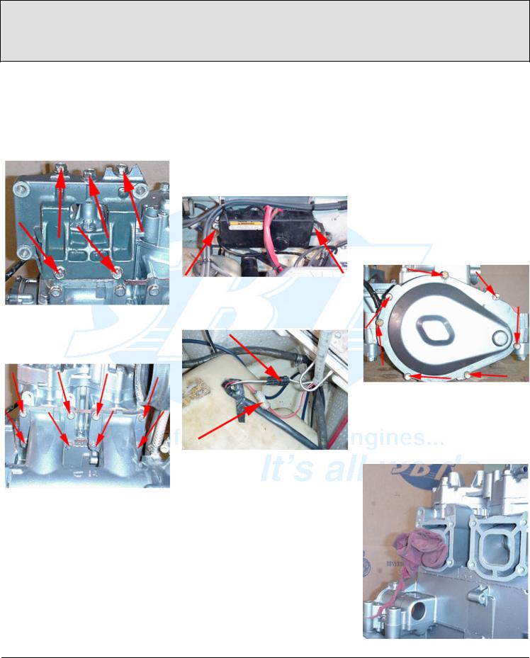
3.7 (Below) Remove the five 14mm bolts securing the exhaust bracket to the cylinders and remove it.
3.8 (Below) Remove the eight 12mm bolts from the exhaust manifold and remove it.
Step 4
Engine removal
4.1 (Below) Remove the two 12mm bolts securing the electrical box and remove it.
4.2 (Below) Disconnect the starter switch wires at the harnesses.
Disconnect the positive wire at the starter with a 10mm socket.
Remove the PTO coupler cover with a 10mm socket.
Remove the four 12mm bolts from the motor mounts, releasing the engine. Slide it slightly forward in the hull to disconnect the PTO coupler from the driveshaft, and lift the engine out of the hull.
Step 5
Accessory Removal
With the engine on the ground, workbench or some other solid surface, begin removing the external accessories that will NOT be shipped with the core.
5.1 (Below) Remove the seven 10mm bolts securing the flywheel cover to the housing, and remove it.
5.2 (Below) Stuff a rag into an open exhaust port. This will prevent the engine from turning over while removing the flywheel and PTO coupler.
v 1.2 |
© 2001 Short Block Technologies |
3
 Loading...