


VL-1000
OO
PERATINGPERATING
O
PERATING
PERATINGPERATING
OO
M M
M
M M
ANUALANUAL
ANUAL
ANUALANUAL
VERTEX STANDARD CO., LTD.
4-8-8 Nakameguro, Meguro-Ku, Tokyo 153-8644, Japan
VERTEX STANDARD U.S.A. Inc.
6125 Phyllis Drive, Cypress, California 90630, U.S.A.
YAESU UK LTD.
Unit 12, Sun Valley Business Park, Winnall Close
Winchester, Hampshire, SO23 0LB, U.K.
VERTEX STANDARD HK LTD.
Unit 1306-1308, 13F., Millennium City 2, 378 Kwun Tong Road,
Kwun Tong, Kowloon, Hong Kong
VERTEX STANDARD (AUSTRALIA) PTY., LTD.
Tally Ho Business Park, 10 Wesley Court, East Burwood, VIC, 3151

General Description
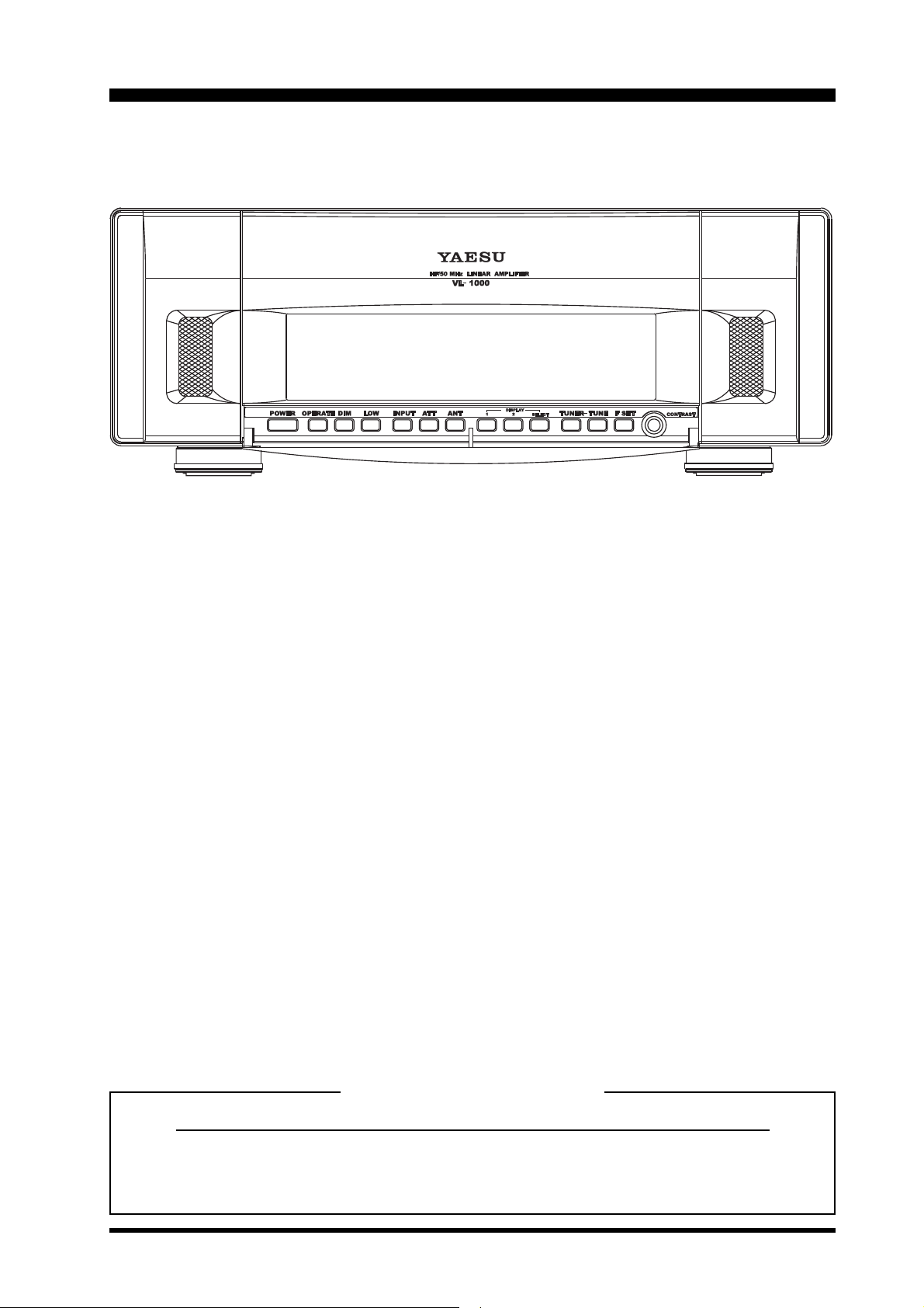
Congratulations! You are now the owner of the Yaesu VL-1000 Linear Amplifier, which brings
you leading-edge technology for the ultimate in operating convenience and reliability. We appreciate your investment in Yaesu equipment, and wish you many years of satisfying operation using
your new amplifier!
The VL-1000 is an all-solid-state linear amplifier operating on the 160 through 6 meter amateur
bands (USA version: 160-15 meters) at a power output level of 1000 Watts on CW and SSB (500
Watts on continuous data modes such as RTTY). The VL-1000 includes a built-in antenna tuner
with 240 memories for tuning data, and microprocessor control of the tuning circuitry. The VL-1000
features input jacks for two different exciters, as well as four antenna jacks for connection of
antennas for different bands. Extensive self-test, system monitoring, and protection circuits are
provided, with status and tuning information being displayed on a huge Liquid Crystal Display
panel.
The separate VP-1000 Power Supply Unit provides the +48 Volts required by the PA transistors, as well as all required control voltages for the amplifier. The VL-1000 normally is powered via
220 Volt AC mains, although it can be operated, at the 500 Watt level, from 117 Volt AC power.
We encourage you to read this manual thoroughly before beginning installation and operation
of your VL-1000 Linear Amplifier. The details regarding proper installation and operating advice
contained in these pages will help you derive maximum satisfaction from your new Yaesu equipment. Be certain to observe all due safety precautions when using this high-power device!
Supplied Accessories
Item Quantity
ALC Cable (T9101489; 2 m) 1
Band Data Cable (T9101487A; 8-pin DIN 8-pin DIN, 2 m) 1
Control Cable (T9101491; D-sub 15-pin RCA, 2 m) 1
Page 1VL-1000 Operating Manual
Installation
The proper, safe installation of the VL-1000
is not difficult to accomplish, using the guidelines to follow.
Caution!
Lethal AC and RF voltages are present
within the cabinets of the VL-1000 Linear Amplifier and VP-1000 Power Supply. Use extreme caution when opening the cabinet(s) to perform any
alignment or adjustment steps, and
take particular care to inspect interconnection cables frequently to ensure that they are in good condition.
It is assumed that you possess technical knowledge and experience consistent with your possession of an
amateur radio license; this knowledge
and experience are important tools
which will aid in the successful installation of this apparatus. Should you
have any questions about the safe installation of this equipment, consult
your Yaesu dealer or seek the assistance of a professional installer.
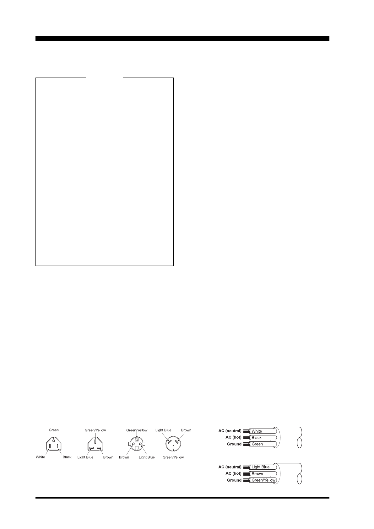
However, the AC power cable/plug configuration will be somewhat different, depending
on the country in which you purchased your
amplifier. In some countries, the VP-1000 is
shipped with the standard 220 Volt connector
appropriate for your location. In those areas
where there are multiple 220 Volt connectors
in common use, the VP-1000 is shipped with-
out the power connector; one may be obtained
at a local hardware or electrical supply store.
Pictorial diagrams of the common 220 and
117 Volt AC connectors in use are shown below. When wiring your own connector, be absolutely certain to observe the proper polarity
on the pin connections. Consult with an electrician if you have any doubts about your wiring!
Be sure that your house wiring is capable
of sufficient current capacity on the 220 Volt
circuit to be used, especially if this circuit is
shared with household appliances. It always
is preferable to operate the VL-1000 from a
dedicated 220 Volt circuit with its own circuit
breaker.
AC Power Connections
(using VP-1000 Power Supply)
The VL-1000 is usually operated from 220
Volt (nominal) AC power. With 220 Volt input
to the VP-1000 Power Supply, full (1000 W)
power output will be obtained from the VL1000, while 117 Volt input to the VP-1000 is
possible at the 500 Watt power output level.
The advanced switching-regulator power
supply used in the matching VP-1000 Power
Supply does not require any transformer rewiring, nor any changing of a switch position;
the power supply will operate from either 220
or 117 Volt line voltages without configuration
changes.
Transceiver or Exciter
Interconnections
The interface wiring to the transceiver or trans-
mitter which drives the VL-1000 consists of:
(A) A 50 Ω coaxial cable for carrying RF drive
power from each exciter to the amplifier;
(B) A 2-conductor transmit/receive control
cable which provides a closure to ground
signal from the transceiver to the amplifier
during transmission;
(C) A (supplied) 2-conductor ALC (Automatic
Level Control) line, used to limit the drive
level from the exciter to the amplifier; and
(D) When using a compatible Yaesu trans-
VP-1000 AC Cable wiring
(U.S.A version)
USA
Plug
UK Plug Australian
(viewed from plug prong side)
European
Plug
Plug
(European version)
Page 2 VL-1000 Operating Manual
Installation
ceiver, a B
nected which provides automatic band
change and T/R control (thus eliminating
the need for cable (B) above), and +48 V
DC supply voltage On/Off control (if the
REMOTE switch on the rear panel of the
VL-1000 is set to the ON position).
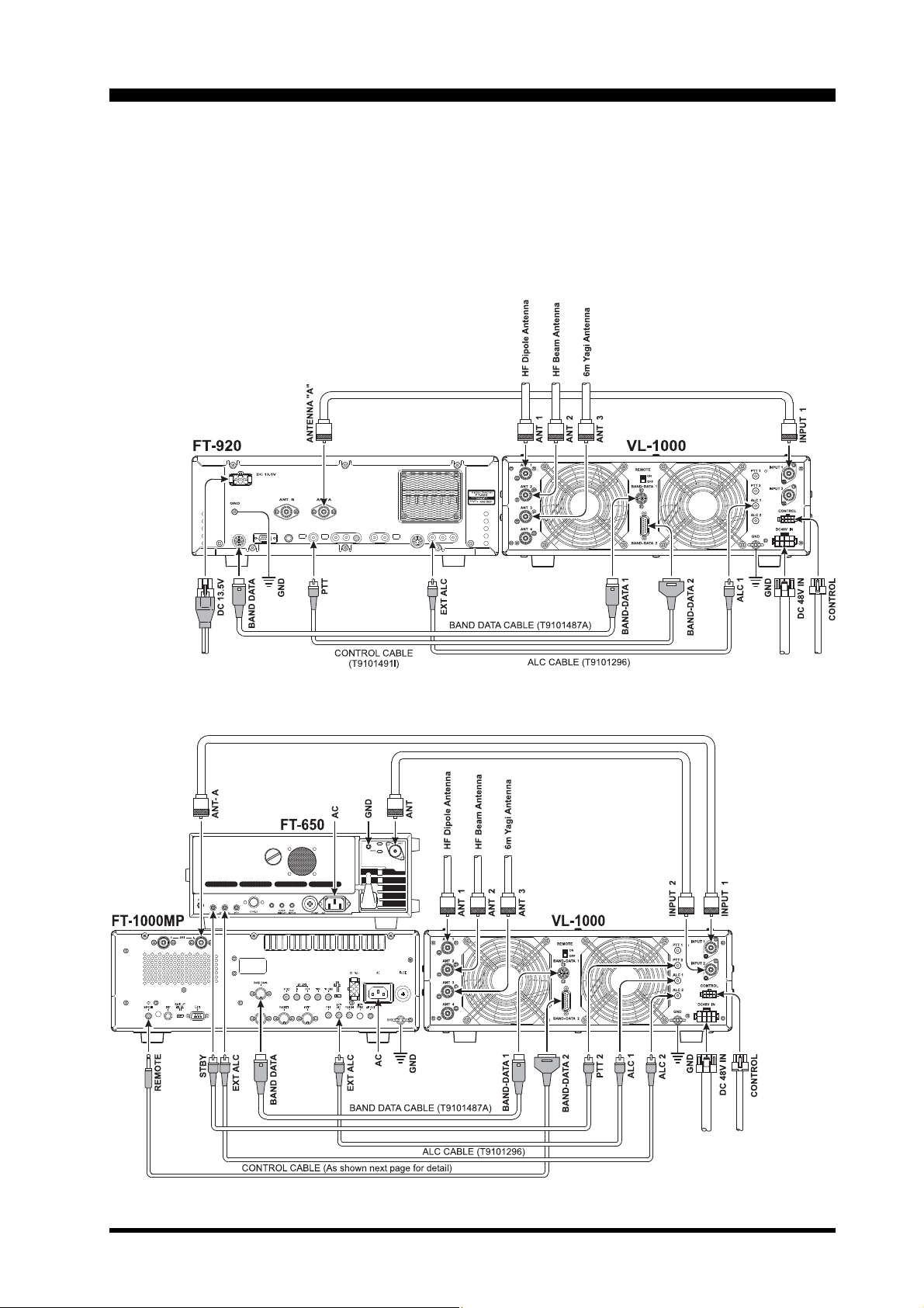
Typical installation diagrams are shown
below. When two exciters are utilized, be certain that all the cables from exciter #1 are con-
AND DATA cable may be con-
nected to the INPUT 1/PTT 1/ALC 1 jacks, and
that all cables from exciter #2 are connected
to the INPUT 2/PTT 2/ALC 2 jacks. When using a B
do not need the PTT cable for the corresponding exciter, as the T/R control signal will be
made via the B
AND DATA cable for interconnection, you
AND DATA cable.
FT-920/VL-1000
FT-1000MP/FT-650/VL-1000
Page 3VL-1000 Operating Manual
Installation
Antenna Connections
As many as four HF or 50 MHz antennas
may be connected to the rear panel Antenna
jacks, labeled ANT 1 ~ ANT 4. The antenna to
be used on a particular band will be memorized once you make the selection manually
via the front panel ANT switch. See the “Op-
eration” section of this manual for more details.
ALC Connections
The VL-1000 provides negative-going ALC,
which provides a negative voltage to the exciter which begins to appear when sufficient
drive power from the exciter is being received;
the voltage becomes of greater (negative)
magnitude if the drive is increased, so as to
prevent overdrive of the amplifier. The voltage
range provided from the VL-1000 is 0 to 10
Volts DC, and this is compatible with all Yaesu
transceivers as well as many exciters of other
manufacture. At 1000 Watts of output power,
the typical voltage generated for use with
Yaesu transceivers is about 4 V DC.
connections labeled TX GND on the rear panel
of the transceiver; do not, however, use the
transceiver’s P
PTT input (via a footswitch, etc.), not for amplifier control.
TT jack, as it was designed for
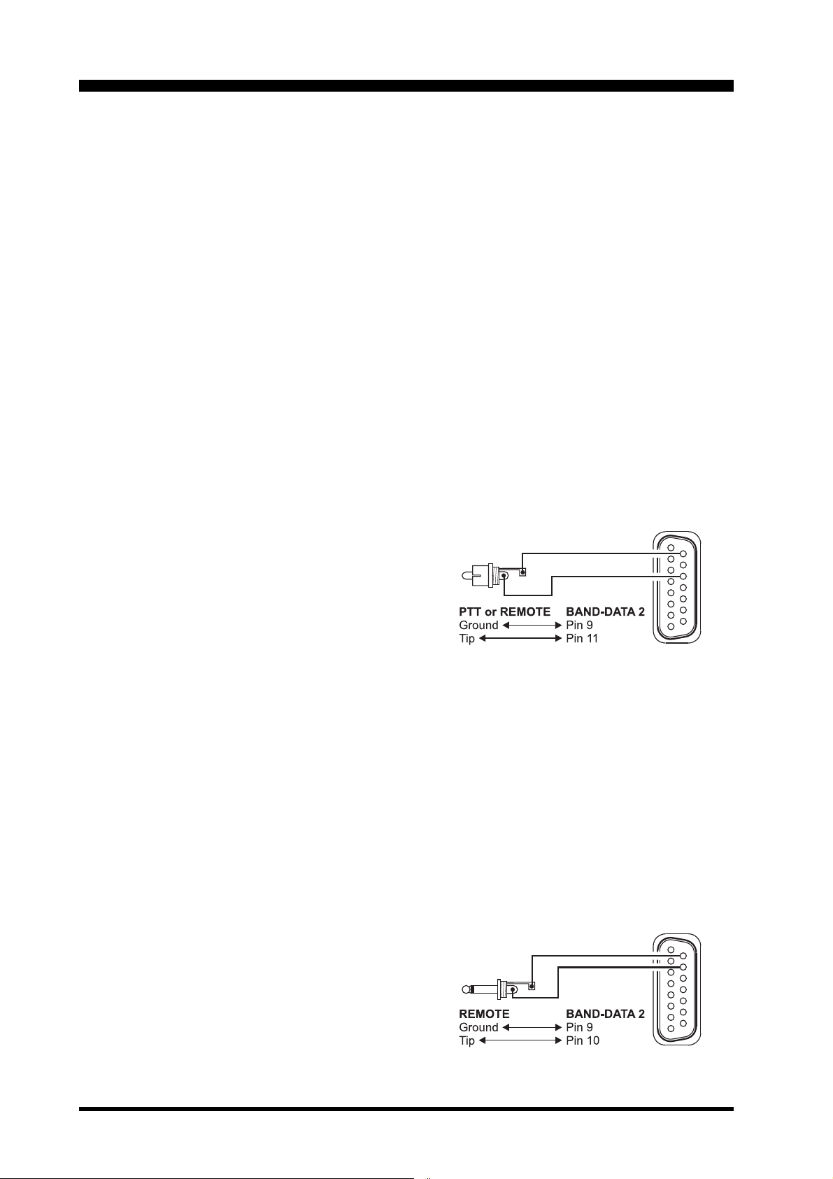
Automatic Amplifier Tune-Up
If you connect the supplied control cable between the transceiver’s P
the VL-1000’s BAND-DATA 2 jack, the transceiver will automatically transmit when you
press the amplifier’s front panel F SET key
(make sure that the M
ceiver is set to CW, RTTY, or some other continuous mode, and set the D
control fully clockwise, if you want to perform
antenna tuning). To accomplish this function,
pin 11 of the BAND-DATA 2 jack closes the
transceiver’s P
placing the transceiver in the transmit condition.
TT or REMOTE jack to ground, thus
TT or REMOTE jack and
ODE switch of the trans-
RIVE or RF PWR
The ALC cable must be connected between
the transceiver and VL-1000 to prevent overdrive of the amplifier, and especially to facilitate the proper operation of the protection circuitry if sudden antenna system problems
should cause the SWR to rise to dangerous
levels.
PTT Connections
These jacks, labeled PTT 1 and PTT 2, accept T/R control signals from your exciter.
Grounding the center pin of one of these PTT
jacks will cause the amplifier to be placed in
the “Transmit” mode.
These jacks utilize a positive voltage (5V
DC) at very low current (10 mA maximum), so
they are compatible with most open-collector
NPN transistor amplifier control circuits in modern transceivers. Mechanical relays may also
be used, so long as they are “floating” contacts that do not apply a voltage to the VL1000’s PTT jacks. On Yaesu transceivers, use
either the transistor or relay (Normally Open)
Automatic Amplifier Tune-Up
using FT-1000MP Transceiver
When using the VL-1000 in conjunction with
the FT-1000MP transceiver, the front panel F
SET key may be used to initiate an automatic
tuning procedure for the amplifier. In order to
accomplish this, Menu Item 7-9 on the FT1000MP must be set to “KEYER ” (which is its
default value), and a control cable must be connected between the FT-1000MP’s R
and the VL-1000’s BAND-DATA 2 jack. The
required wiring for this cable is shown below.
EMOTE jack
Page 4 VL-1000 Operating Manual
 Loading...