

Page 1
OPERATING MANUAL
VERTEX STANDARD CO., LTD.
4-8-8 Nakameguro, Meguro-Ku, Tokyo 153-8644, Japan
VERTEX STANDARD
US Headquarters
17210 Edwards Rd., Cerritos, CA 90703, U.S.A.
International Division
8350 N.W. 52nd Terrace, Suite 201, Miami, FL 33166, U.S.A.
YAESU EUROPE B.V.
P.O. Box 75525, 1118 ZN Schiphol, The Netherlands
YAESU UK LTD.
Unit 12, Sun Valley Business Park, Winnall Close
Winchester, Hampshire, SO23 0LB, U.K.
YAESU GERMANY GmbH
Am Kronberger Hang 2, D-65824 Schwalbach, Germany
VERTEX STANDARD HK LTD.
11th Floor Tsim Sha Tsui Centre, 66 Mody Rd.,
Tsim Sha Tsui East, Kowloon, Hong Kong
Page 2

Contents
Introduction ...................................................... 1
Specifications .................................................... 2
Accessories & Option ...................................... 3
Installation ........................................................ 4
Preliminary Inspection ....................................... 4
Installation Tips ................................................. 4
Safety Information ............................................. 5
Antenna Considerations ..................................... 6
Mobile Installation ............................................. 8
Transceiver Installation .................................. 8
Mobile Power Connections ............................ 9
Mobile Speakers ........................................... 9
Base Station Installation ....................................10
AC Power Supplies ......................................10
Packet Radio Terminal Code Controller (TNC)
Front Panel Controls, Switches ................... 12
LCD .................................................................. 14
Rear Panel Connections ................................ 15
MH-48A6J Microphone .................................. 16
MH-42B6JS Microphone................................. 17
Operation ........................................................ 18
Basic Operation/Reception ................................18
Turning the Power On/Off ............................ 18
Adjusting the Volume and Squelch ................18
RF Squelch ..................................................18
Frequency Display and Band Change ............19
Main Dial Tuning.........................................19
Direct Keypad Frequency Entry
(Requires MH-48
A6J
)...........................19
Channel Step Selection .................................20
VFO tracking ...............................................20
Receiver Muting ..........................................21
VHF-VHF (V-V) or
UHF-UHF (U-U) Operation ................. 21
Lock Feature ................................................ 22
Keypad Beeper ............................................ 22
Display Brightness ....................................... 22
Transmission .................................................... 23
Power Output Setting ...................................23
PTT Locking................................................23
Repeater Splits ............................................. 24
Automatic Repeater Shift (ARS) ...................24
Separate Transmit Frequency Memories ........ 25
Standard Repeater Shift ................................25
Tone Squelch System ...................................26
Tone Search Scanning ..................................27
CTCSS Bell Paging ......................................27
1750 Hz Tone Calling (European Versions) ...27
DTMF Tone Generation (MH-48
A6J
only) ......28
....10
DTMF Autodialer Operation ......................... 28
Transmitter Time-Out Timer (TOT)...............30
Memory Operation ........................................ 31
Memory Storage ............................................... 31
Storing independent Transmit Frequencies
(“Odd Splits”) .....................................31
Recalling Memories ..........................................32
Direct Keypad Memory Recall
(Requires MH-48
A6J
)...........................32
Memory Offset Tuning ................................. 33
Masking a Memory ..........................................33
Transferring Memory Channels ......................... 34
Memory only Mode ..........................................34
Scanning Feature ........................................... 35
Scanning Operation .......................................... 35
Scan-Resume Options .................................. 35
Memory Skip Scanning ....................................36
Temporary Memory Skip .............................. 36
Programmable Band-Scan Limit ........................37
Priority Channel Operation................................38
VFO Priority ................................................38
Memory Priority ..........................................38
HOME Priority ............................................ 38
Smart Search .................................................. 39
ARTS: Auto Range Transponder System .. 40
ARTS Modes ................................................... 40
CW ID (Morse identifier) Setup ........................ 41
Miscellaneous Settings .................................. 42
Sub-Display Options.........................................42
Automatic Power-Off .......................................42
Programming the microphone Button Functions
.......43
DCS Code Inversion .........................................44
External Speaker Selection ................................ 45
Microprocessor Reset Procedures............... 46
Cloning ............................................................. 47
Menu System................................................... 48
Menu Selection Details .....................................50
Page 3
INTRODUCTION
The FT-7100M is a ruggedly-built, high quality Dual Band FM transceiver providing 50
Watts of power output on the 144 MHz Amateur band, and 35 Watts on the 430 MHz band.
The high power output of the FT-7100M is produced by its 2SK3478 Power MOS FET
amplifier, with a direct-flow heat sink and thermostatically-controlled cooling fan maintaining
a safe temperature for the transceiver’s circuitry.
Featuring 262 memory channels, dual receive with independent Volume and Squelch controls, and built-in CTCSS and DCS encoder/decoder circuits, the FT-7100M includes provision for remote-head mounting, utilizing the optional YSK-7100 Separation Kit, which allows installation evening the most compact of cars.
We recommend that you read this manual in its entirety, so as to understand fully the many
features of your new FT-7100M transceiver.
1FT-7100M Operating Manual
Page 4

SPECIFICATIONS
General
Frequency Range: RX: 108.00 – 180.00 MHz
320 – 480 MHz
810 – 999.990 MHz (Cellular Blocked)
TX: 144 – 146 MHz or 144 – 148 MHz
430 – 440 MHz or 430 – 450 MHz
Channel Steps: 5/10/12.5/15/20/25/50 kHz
Mode of Emission: F3, F2, F1
Antenna Impedance: 50 Ω, unbalanced (Antenna Duplexer built-in)
Frequency Stability: ±5 ppm @ 14° F ~ +140° F (–10 °C ~ +60 °C)
Operating Temperature Range: –4° F ~ +140° F (–20 °C ~ +60 °C)
Supply Voltage: 13.8 VDC (±15%), negative ground
Current Consumption (Approx.): RX: 0.5 A (Squelched)
TX: 11.5 A (VHF), 10.0 A (UHF)
Case Size (WxHxD): 5.8 x1.9 x 6.9 inches (140 x 38 x 166 mm)
(w/o knobs & connectors)
Weight (Approx.): 2.2 lb (1 kg)
Transmitter
Output Power: 50/20/10/5 W (VHF), 35/20/10/5 W (UHF)
Modulation Type: Variable Reactance
Maximum Deviation: ±5 kHz
Spurious Radiation: Better than –60 dB
Modulation Distortion: Less than 3%
Microphone Impedance: 2 kΩ
DATA Jack Impedance: 10 kΩ
Receiver
Circuit Type: Double-conversion superheterodyne
Intermediate Frequencies: 21.7 MHz/450 kHz (VHF), 45.05 MHz/455 kHz (UHF)
Sensitivity (for 12dB SINAD): Better than 0.16 µV
Squelch Sensitivity: 0.1 µV
Image Rejection: 70 dB
Selectivity (–6dB/–60dB): 12 kHz/24 kHz
Maximum AF Output: 2 W @ 8 Ω for 5% THD
AF Output Impedance: 4-16 Ω
Specifications are subject to change without notice, and are guaranteed within the 144
and 430 MHz amateur bands only.
Frequency ranges will vary according to transceiver version; check with your dealer.
2 FT-7100M Operating Manual
Page 5

ACCESSORIES & OPTION
SUPPLIED ACCESSORIES
Microphone MH-48A6J or MH-42B6JS (depending on transceiver version) ...1
Mobile Mounting Bracket MMB-36 .............................................................................. 1
DC Power Cord w/Fuse T9021715 .............................................................................. 1
Spare Fuse 15A (Q0000081).................................................................... 2
Operating Manual..........................................................................................................1
Warranty Card ...............................................................................................................1
OPTIONAL ACCESSORIES
MH-48A6J DTMF Microphone
MH-42B6JS Hand Microphone
YSK-7100 Separation Kit
MEK-2 Microphone Extension Kit
MMB-60 Quick Release Mobile Mounting Bracket
MMB-62 Remote Front Panel Mounting Bracket
SP-7 External Speaker
MLS-100 High-Power External Speaker
FP-1023 AC Power Supply (25A: USA only)
FP-1030A AC Power Supply (30A)
CT-39A Packet Interface Cable
AD-3 VHF-UHF Duplexer for Two-antenna Operation
ADMS-2 WindowsTM PC Programming Software
Availability of accessories may vary. Some accessories are supplied as standard per local
requirements, while others may be unavailable in some regions. Consult your Yaesu dealer
for details regarding these and any newly-available options Connection of any non-Yaesuapproved accessory, should it cause damage, may void the Limited Warranty on this apparatus.
3FT-7100M Operating Manual
Page 6

INSTALLATION
This chapter describes the installation procedure for integrating the FT-7100M into a typical amateur radio station. It is presumed that you possess technical knowledge and conceptual understanding consistent with your status as a licensed radio amateur. Please take some
extra time to make certain that the important safety and technical requirements detailed in this
chapter are followed closely.
PRELIMINARY INSPECTION
Inspect the transceiver visually immediately upon opening the packing carton. Confirm that
all controls and switches work freely, and inspect the cabinet for any damage. Gently shake
the transceiver to verify that no internal components have been shaken loose due to rough
handling during shipping.
If any evidence of damage is discovered, document it thoroughly and contact the shipping company (or your local dealer, if the unit was purchased over-the-counter) so as to get
instructions regarding the prompt resolution of the damage situation. Be certain to save the
shipping carton, especially if there are any punctures or other evidence of damage incurred
during shipping; if it is necessary to return the unit for service or replacement, use the
original packing materials but put the entire package inside another packing carton, so as to
preserve the evidence of shipping damage for insurance purposes.
INSTALLATION TIPS
To ensure long life of the components, be certain to provide adequate ventilation around the
cabinet of the FT-7100M.
Do not install the transceiver on top of another heat-generating device (such as a power
supply or amplifier), and do not place equipment, books, or papers on top of the FT-7100M.
Avoid heating vents and window locations that could expose the transceiver to excessive
direct sunlight, especially in hot climates. The FT-7100M should not be used in an environment where the ambient temperature exceeds +140° F (+60° C).
4 FT-7100M Operating Manual
Page 7
INSTALLATION
SAFETY INFORMATION
The FT-7100M is an electrical apparatus, as well as a generator of RF (Radio Frequency)
energy, and you should exercise all safety precautions as are appropriate for this type of
device. These safety tips apply to any device installed in a well-designed amateur radio
station.
Never allow unsupervised children to play in the vicinity of your transceiver or
antenna installation.
Be certain to wrap any wire or cable splices thoroughly with insulating electrical tape,
to prevent short circuits.
Do not route cables or wires through door jambs or other locations where, through
wear and tear, they may become frayed and shorted to ground or to each other.
Do not stand in front of a directional antenna while you are transmitting into that
antenna. Do not install a directional antenna in any location where humans or pets
may be walking in the main directional lobe of the antenna’s radiation pattern.
In mobile installations, it is preferable to mount your antenna on top of the roof of the
vehicle, if feasible, so as to utilize the car body as a counterpoise for the antenna and
raise the radiation pattern as far away from passengers as possible.
During vehicular operation when stopped (in a parking lot, for example), make it a
practice to switch to Low power if there are people walking nearby.
Never wear dual-earmuff headphones while driving a vehicle.
Do not attempt to drive your vehicle while making a telephone call on an autopatch
using the DTMF microphone. Pull over to the side of the road, whether dialing
manually or using the auto-dial feature.
5FT-7100M Operating Manual
Page 8

INSTALLATION
A NTENNA CONSIDERATIONS
The FT-7100M is designed for use with antennas presenting an impedance of near 50 Ohms
at all operating frequencies. The antenna (or a 50 W dummy load) should be connected
whenever the transceiver is turned on, to avoid damage that could otherwise result if transmission occurs accidentally without an antenna.
Ensure that your antenna is designed to handle 50 Watts of transmitter power. Some magnetic-mount mobile antennas, designed for use with hand-held transceivers, may not be
capable of withstanding this power level. Consult the antenna manufacturer’s specification
sheet for details.
Most all FM work is performed using vertical polarization. When installing a directional
antenna such as a Yagi or Cubical Quad, be certain to orient it so as to produce vertical
polarization, unless you are engaged in a special operating situation where horizontal polarization is used. In the case of a Yagi antenna, orient the elements vertically for vertical
polarization; for a Cubical Quad, the feedpoint should be at the center of one of the vertical
sides of the driven element (or at a side corner, in the case of a diamond-shaped Cubical
Quad).
Note that this transceiver is designed with wide frequency coverage in the VHF/UHF spectrum. For general listening, you may wish to have a broadband antenna such as a discone
available, as a directional antenna such as a Yagi will have degraded performance outside the
Amateur band for which it is designed.
Excellent reference texts and computer software are available for the design and optimization
of VHF and UHF antennas. Your dealer should be able to assist you with all aspects of your
antenna installation requirements.
Use high-quality 50 Ohm coaxial cable for the lead-in to your FT-7100M transceiver. All
efforts at providing an efficient antenna system will be wasted if poor quality, lossy coaxial
cable is used. Losses in coaxial lines increase as the frequency increases, so an 8-meter-long
(25’) coaxial line with 1/2 dB of loss at 28 MHz may have a loss of 6 dB or more at 446 MHz;
choose your coaxial cable carefully based on the installation location (mobile vs. base) and
the overall length of the cable required (for very short runs of cable in a mobile installation,
the smaller, more flexible cable types may be acceptable).
6 FT-7100M Operating Manual
Page 9
INSTALLATION
A NTENNA CONSIDERATIONS
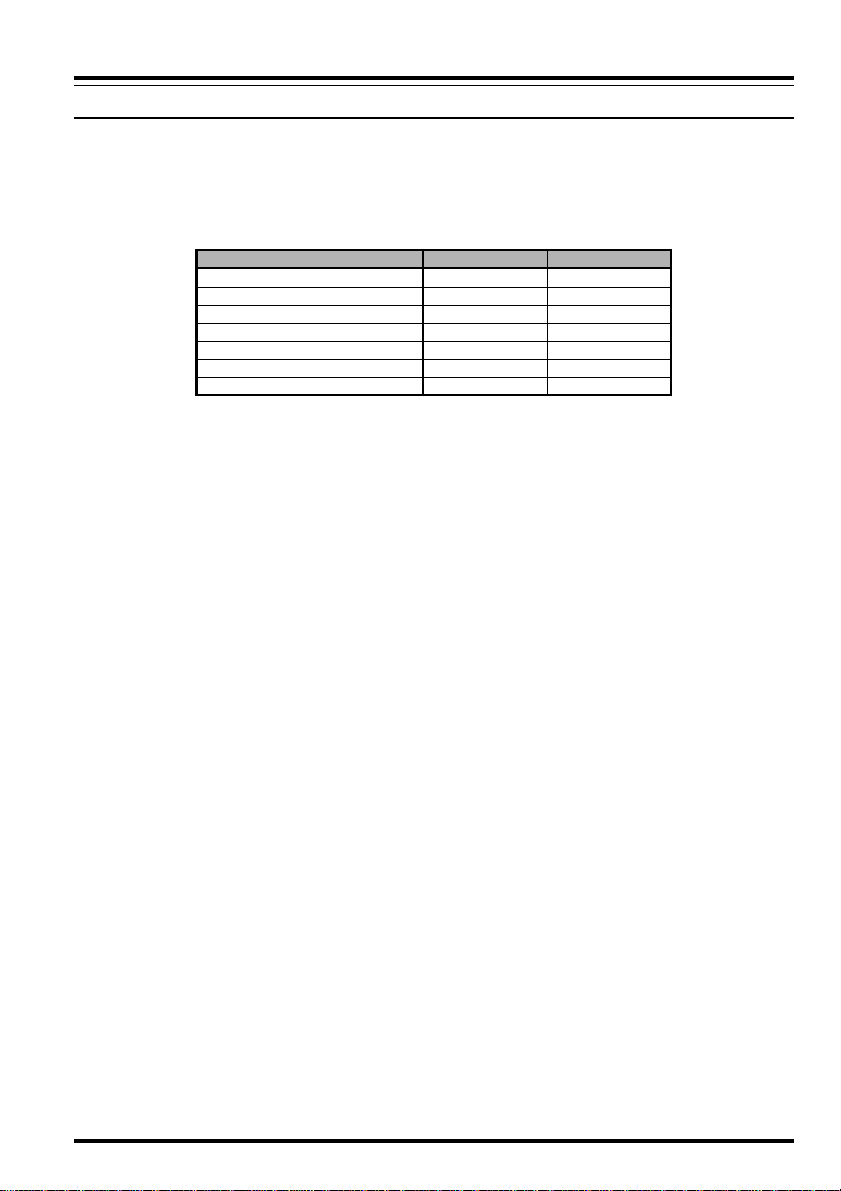
For reference, the chart below shows approximate loss figures for typically-available coaxial
cables frequently used in VHF/UHF installations.
Loss in dB per 30 m (100 feet) for Selected 50-Ohm Coaxial Cables
(Assumes 50-ohm Input/Output Terminations)
CABLE TYPE
RG-58A
RG-58 Foam
RG-213
RG-8 Foam
Belden 9913
Times Microwave LMR-400
7/8” “Hardline”
LOSS: 144 MHZ
6.5
4.7
3.0
2.0
1.5
1.5
0.7
LOSS: 430 MHZ
> 10
8
5.9
3.7
2.9
2.6
1.3
Loss figures are approximate; consult cable manufacturers’
catalogs for complete specifications.
In outdoor installations, be certain to weatherproof all connectors thoroughly, as water
entering a coaxial cable will cause losses to escalate rapidly, thus diminishing your communications effectiveness. The use of the shortest possible length of the highest quality coaxial cable that fits within your budget will ensure the best performance from your FT-
7100M.
7FT-7100M Operating Manual
Page 10
INSTALLATION
MOBILE INSTALLA TION
The FT-7100M must only be installed in vehicles having a 13.8 Volt negative ground electrical system. Mount the transceiver where the display, controls, and microphone are easily
accessible, using the supplied MMB-36 mounting bracket.
The transceiver may be installed in almost any location, but should not be positioned near
a heating vent nor anywhere where it might interfere with driving (either visually or mechanically). Make sure to provide plenty of space on all sides of the transceiver so that air can flow
freely around the radio’s case. Refer to the diagrams showing proper installation procedures.
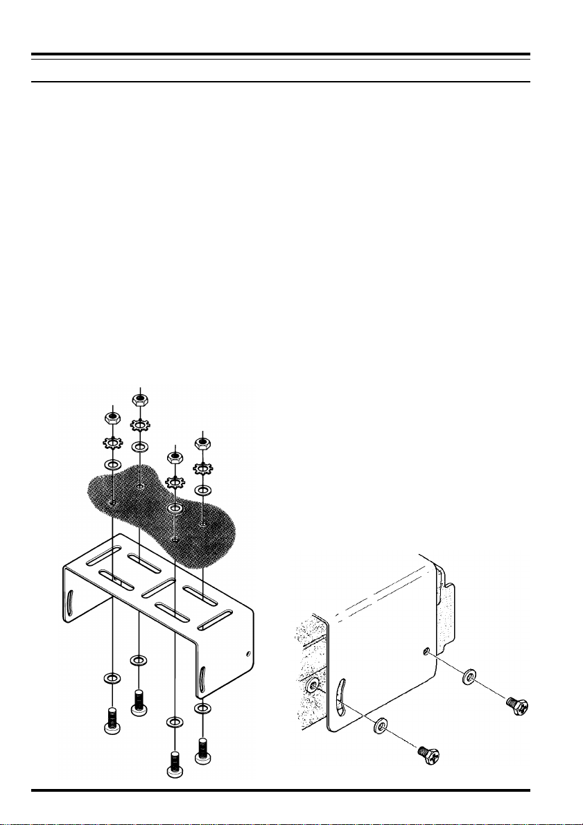
Transceiver Installation
Choose a mounting location with sufficient clearance for the transceiver. Using the mount-
r
ing bracket as a template for the mounting holes, use a 4.8 mm (3/16”) bit to drill the
mounting holes, and secure the mounting bracket with the supplied screws, washers,
and nuts (see diagram).
Position the transceiver in the bracket so that the holes in the side are aligned with those
r
in the bracket, and bolt the transceiver into place using the supplied short screws and flat
washers.
8 FT-7100M Operating Manual
Page 11
INSTALLATION
MOBILE INSTALLA TION
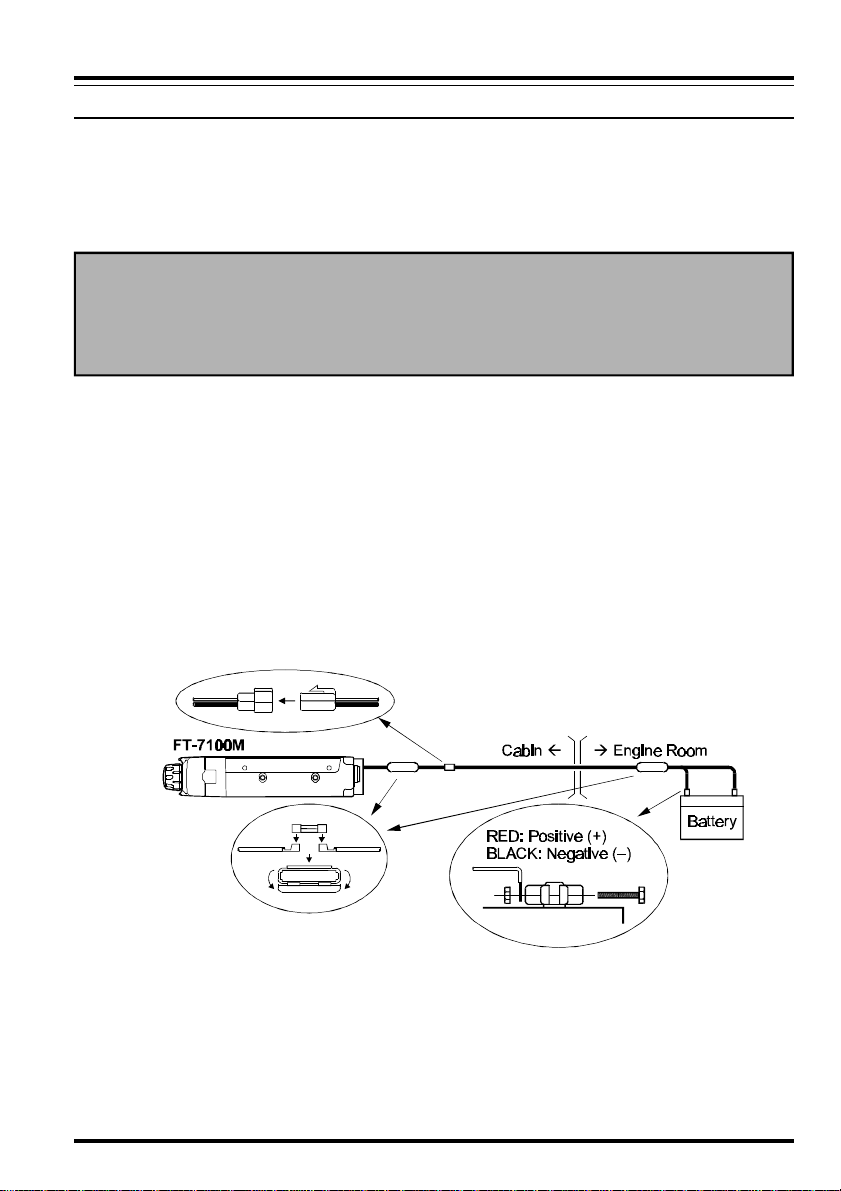
Mobile Power Connections
To minimize voltage drop and avoid blowing the vehicle’s fuses, connect the supplied DC
power cable directly to the battery terminals. Do not attempt to defeat or bypass the DC
cable’s fuse – it is there to protect you, your transceiver, and your vehicle’s electrical system.
Warning!
Never apply AC power to the power cable of the FT-7100M, nor DC voltage greater
than 15.8 Volts. When replacing the fuse, only use a 15-A fast-blow type. Failure to
observe these safety precautions will void the Limited Warranty on this product.
Before connecting the transceiver, check the voltage at the battery terminals while rev-
r
ving the engine. If the voltage exceeds 15 Volts, adjust the vehicle’s voltage regulator
before proceeding with installation.
Connect the RED power cable lead to the POSITIVE (+) battery terminal, and the BLACK
r
power cable lead to the NEGATIVE (–) terminal. If you need to extend the power cable,
use #12 AWG or larger insulated, stranded copper wire. Solder the splice connections
carefully, and wrap the connections thoroughly with insulating electrical tape.
Before connecting the cable to the transceiver, verify the voltage and polarity of the
r
voltage at the transceiver end of the DC cable using a DC voltmeter. Now connect the
transceiver to the DC cable.
Mobile Speakers
The optional SP-7 External Speaker includes its own swivel-type mounting bracket, and is
available from your Yaesu dealer.
Other external speakers may be used with the FT-7100M , if they present the specified 8-Ohm
impedance and are capable of handling the 2 Watts of audio output supplied by the FT-
7100M.
9FT-7100M Operating Manual
Page 12

INSTALLATION
BASE STATION INSTALLATION
The FT-7100M is ideal for base station use as well as in mobile installations. The FT-7100M
is specifically designed to integrate into your station easily, using the information to follow
as a reference.
AC Power Supplies
Operation of the FT-7100M from an AC line requires a power source capable of providing at
least 15 Amps continuously at 13.8 Volts DC. The FP-1023 and FP-1030A AC Power
Supplies are available from your Yaesu dealer to satisfy these requirements. Other wellregulated power supplies may be used, as well, if they meet the above voltage and current
specifications.
Use the DC power cable supplied with your transceiver for making power connections to the
power supply. Connect the RED power cable lead to the POSITIVE (+) power supply
terminal, and connect the BLACK power cable lead to the NEGATIVE (–) power supply
terminal.
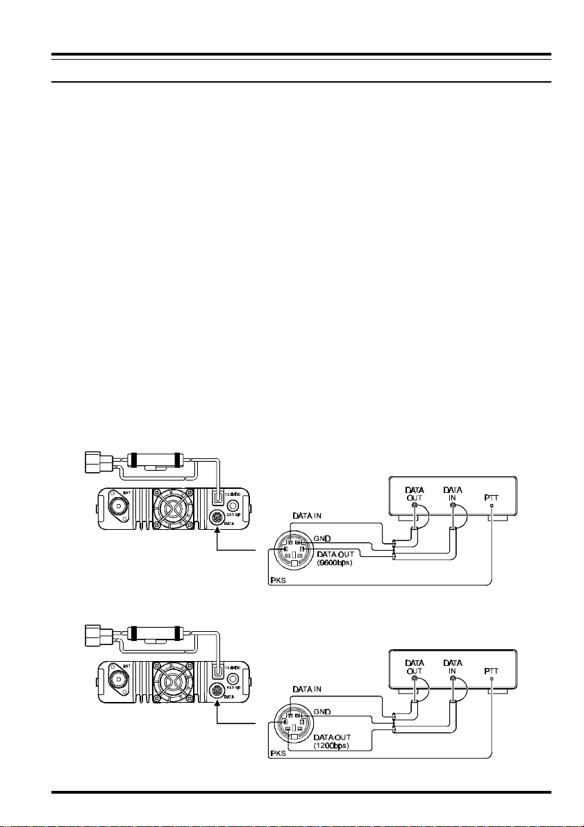
Packet Radio Terminal Node Controller (TNC)
The FT-7100M provides a convenient rear-panel DATA jack for easy connections to your
TNC. This connector is a standard mini-DIN connector. A pre-wired connector and cable
assembly option, model CT-39A, is available from your local Yaesu dealer.
The FT-7100M’s DATA jack connections are optimized for the data transmission and reception speed in use. In accordance with industry standards, the signal levels, impedances, and
bandwidths are significantly different on 9600 bps as opposed to 1200 bps. If your TNC does
not provide multiple lines to accommodate such optimization, you may still be able to utilize
your TNC, if it is designed for multiple-radio use, by connecting the TNC “Radio 1” port to
the 1200 bps lines on the FT-7100M, and the “Radio 2” port to the 9600 bps lines.
The pin connections of the Data connector are shown below.
DATA Jack Pin Out
Pin
Label
1
PKD
2
GND
3
PTT
4
RX9600
5
RX1200
6
SQL
Note
Packet Data Input
Impedance: 10 kΩ,
Maximum Input Level: 40 mV p-p for 1200 bps
2.0 Vp-p for 9600 bps
Signal Ground
Gound to Transmit
9600 bps Packet Data Output
Impedance: 10 kΩ, Maximum Output: 500 mV p-p
1200 bps Packet Data Output
Impedance: 10 kΩ, Maximum Output: 300 mV p-p
Squelch Control
Squelch Open: +5 V, Squelch Close: 0 V
CT-39A Wire Color
Brown
Red
Orange
Yellow
Green
Blue
10 FT-7100M Operating Manual
Page 13
INSTALLATION
BASE STATION INSTALLATION
Note that 9600 bps packet transmit-deviation adjustment is very critical to successful operation, and can only be accomplished using a calibrated deviation meter (such as that found on
an FM Service Monitor used in a communications service center). In most cases, the Packet
Data Input level (set via a potentiometer inside the TNC) must be adjusted to provide a
deviation of ±2.75 kHz (±0.25 kHz). Check with your packet node’s sysop if you have any
questions about the appropriate deviation level for your network. Note also that high throughput on 9600 bps frequently requires strong signals, so you may wish to consider the use of
a directional antenna such as a Yagi for communication with high-speed packet nodes.
The setting of the 1200 bps Packet Data Input level is much less critical than it is at 9600 bps,
and satisfactory adjustment to the optimum (±2.5 ~ ±3.5 kHz) deviation can usually be done
“by ear” by adjusting the TNC’s 1200 bps TX Audio Level potentiometer so that the outgoing packets (as monitored on a separate VHF or UHF receiver) are approximately the same
level as (A) the DTMF tones or (B) the 1750 Hz Burst tone produced using the microphone.
Typical connections to a TNC are shown below.
Finally, note that the (“
or 9600 bps) independently for each band. If you have trouble getting your FT-7100M to
respond correctly during packet operation, check to be certain that you do not have Menu
#19 (
PCKT
) set to the wrong data rate.
PCKT
”) MENU selection allows you to set the Packet data rate (1200
9600 bps Packet Setup
1200 bps Packet Setup
11FT-7100M Operating Manual
Page 14
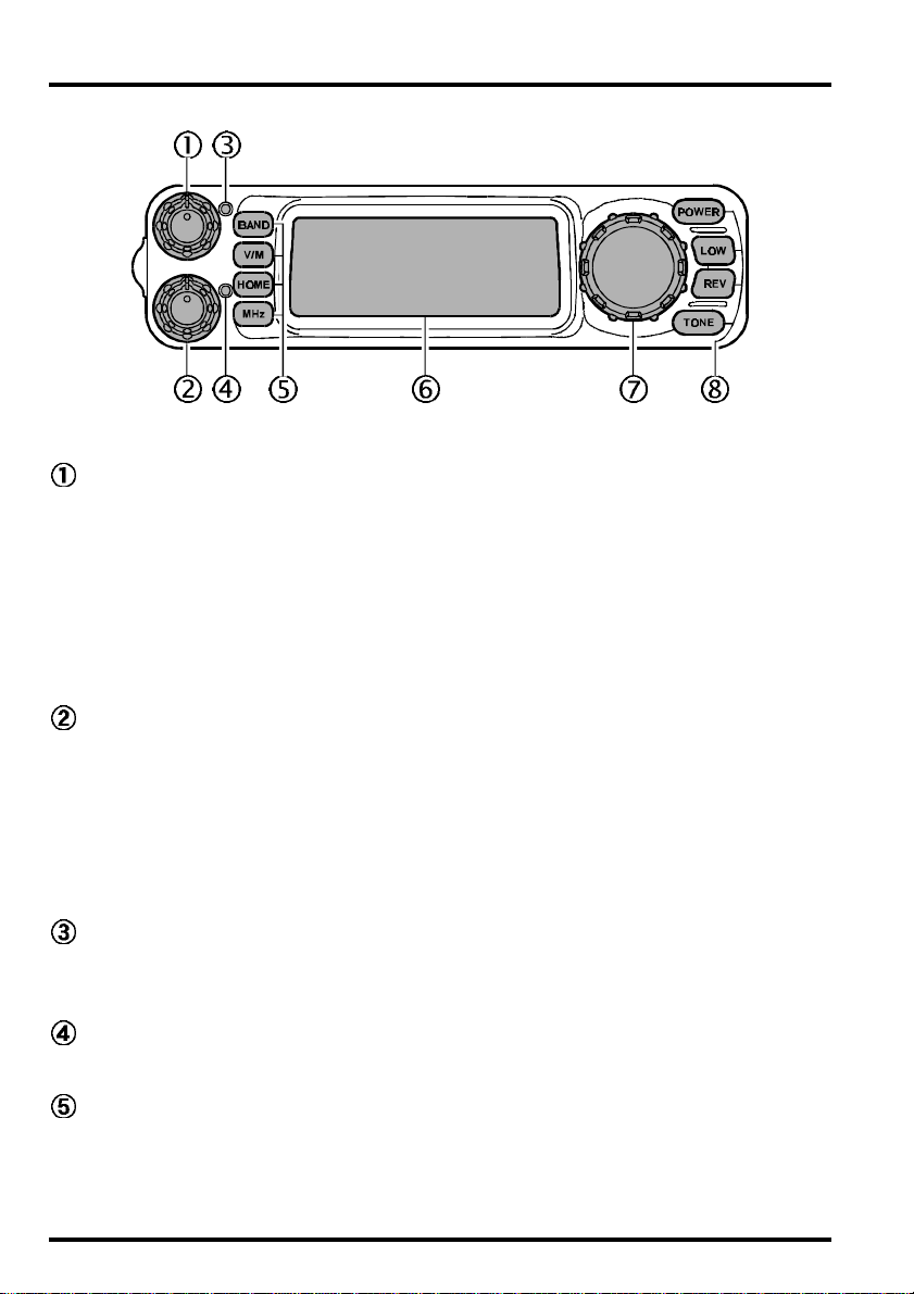
FRONT PANEL CONTROLS, SWITCHES
VOL - SQL (“main” band) Controls
The inner VOL control adjusts the speaker audio level from the “main” band receiver
(default: VHF is the upper band on the display). Clockwise rotation increases the audio
level.
The outer SQL control is used to silence background noise on the “main” band receiver.
It should advanced clockwise just to the point where the noise silenced (and the green
“main” BUSY/TX Indicator turns off), so as to provide the best sensitivity to weak
signals.
VOL - SQL (“sub” band) Controls
The inner VOL control adjusts the speaker audio level from the “sub” band receiver
(default: UHF is the lower band on the display). Clockwise rotation increases the audio
level.
The outer SQL control is used to silence background noise on the “sub” band receiver.
It should advanced clockwise just to the point where the noise silenced (and the green
“sub” BUSY Indicator turns off), so as to provide the best sensitivity to weak signals.
BUSY/TX Indicator (“main” band)
This dual-color LED glows Green when a signal is being received on the “main” band
channel. This LED glows Red when you are transmitting.
BUSY Indicator (“sub” band)
This LED glows Green when a signal is being received on the “sub” band channel.
Command Keys
These four keys select many of the most important operating features on the FT-7100M .
[
BAND] Key: Pressing this key switches “main” band control between the VHF band
and UHF band. Press and hold in this key for 1/2 second to activate the “Menu” mode.
12 FT-7100M Operating Manual
Page 15

FRONT PANEL CONTROLS, SWITCHES
[
V/M] Key: Pressing this key switches frequency control on the “main” band between
the VFO and Memory Systems. Press and hold in this key for 1/2 second to activate the
Memory Write mode.
[
HOME] Key: Pressing this key recalls a favorite “Home” frequency memory. Press and
hold in this key for 1/2 second to activate VHF-VHF or UHF-UHF operation, as opposed
to “normal” VHF-UHF operation.
[
MHz] Key: When this key is pressed in momentarily during VFO or Memory Tune
operation, the Main Dial knob tunes in 1 MHz steps, and if pressed and held for 1/2
second, the Main Dial knob tunes in 10 MHz steps, thus allowing quick frequency
change. When this key is pressed in momentarily during Memory operation, the Memory
Tune feature is activated, allowing offset tuning from a memorized frequency.
LCD (Liquid Crystal Display)
The display consists of segmented digits for frequency readout and various icons
representing enabled transceiver features, and it also contains information regarding
menu programming and alphanumeric names for the memory channels.
Main Dial Knob
This 24-position detented rotary switch is the main tuning dial for the transceiver. It
used for most tuning, memory selection, and function setting tasks on the FT-7100M.
Function Keys
These four keys operate in a manner similar to the Command Keys just described.
[
POWER] Key: This is main On/Off switch for the FT-7100M .
Press and hold in this key for 1/2 second to turn to the transceiver on or off.
[
LOW] Key: Pressing this key repeatedly allows selection of the transmit power. The
selections available are:
LOW à MID2 à MID1 à HIGH à LOW
(5 W) (10 W) (20 W) (35 W: UHF)
(50 W: VHF)
[
REV] Key: Pressing this key reverses the transmit and receive frequencies when a
repeater split is programmed. Press and hold in this key for 1/2 second to activate the
priority scan.
[
TONE] Key: Pressing this key repeatedly allows selection of the CTCSS and DCS mode
and setting of the tone or code to be used. The selections available are:
ENC à ENC/DEC (TONE SQL) à BELL à DCS à OFF à ENC
Rotating the Main Dial knob selects the CTCSS frequency or DCS code.
• • • • • •
• • • • • •
13FT-7100M Operating Manual
Page 16
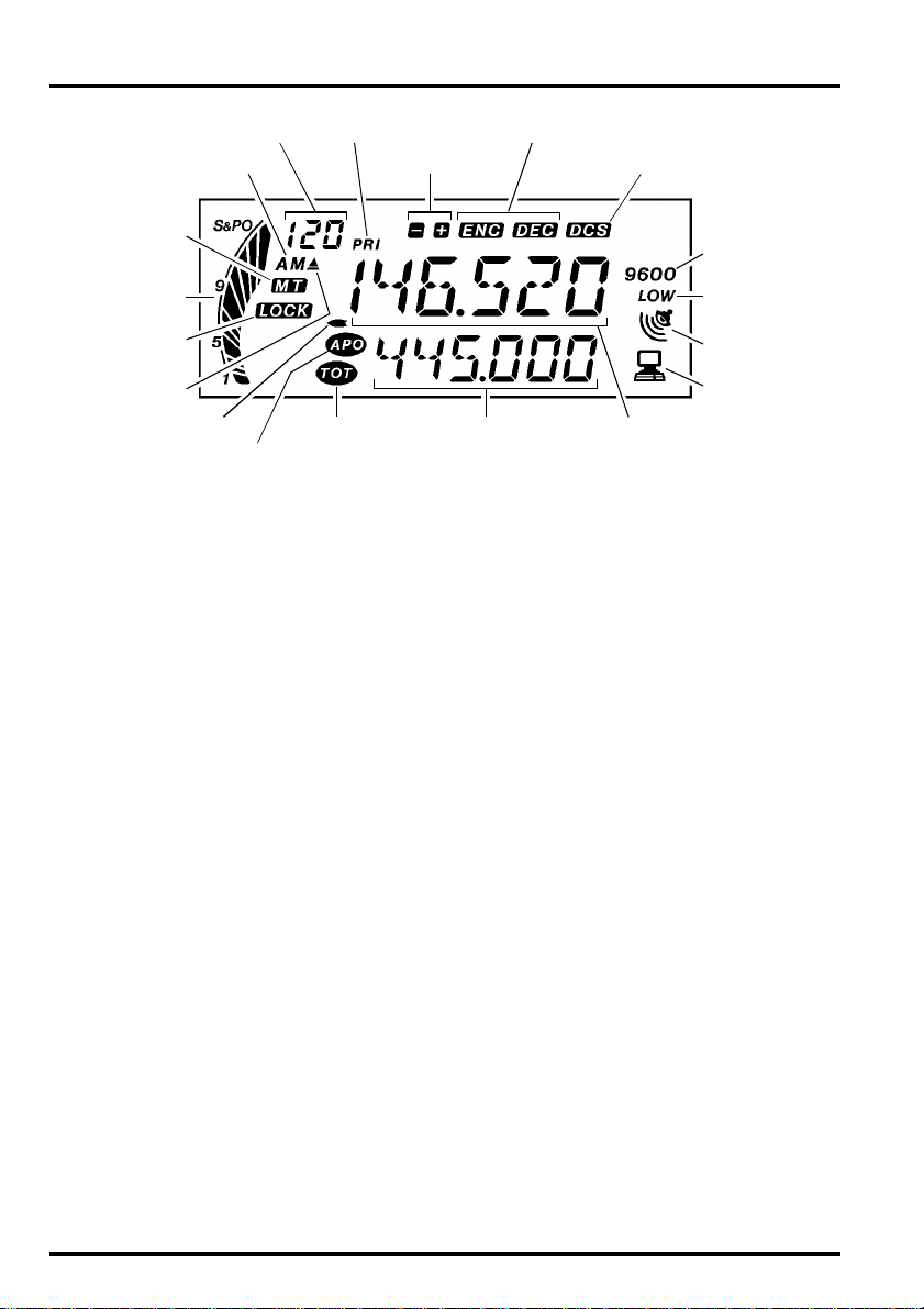
LCD
Memory Channel Number
Memory Tune
S&PO Meter
Keypad/DIAL Lock
Scan Skip Memory
AM Rx
APO Timer
Priority Active
Time-Out TimerPTT Lock
Repeater Shift
CTCSS Encode/Decode
Digtal Code Squelch
Main Band FrequencySub Band Frequency
9600 bps
Data Operation
Low Tx Power
Alert Ringer
Enabled
Packet Operation
14 FT-7100M Operating Manual
Page 17
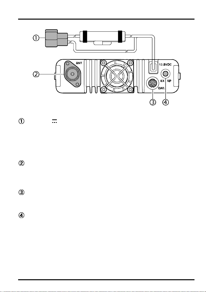
REAR PANEL CONNECTIONS
13.8V DC Cable Pigtail w/Fuse
This is the DC power supply connections for the transceiver. Use the supplied DC cable
to connect this pigtail to the car battery or base station DC power supply (capable of at
least 15 Amperes, continuous duty). Make certain that the RED lead connects to the
Positive side of the power source, and BLACK lead connects to the Negative side of the
power source.
ANT Jack
Connect a dual-band antenna’s 50 Ω cable to this M-type (SO-239) coaxial connector.
European versions are equipped with a Type-N connector. Be certain to use the proper
type of plug for connection of the coaxial cable.
DATA Jack
This 6-pin mini-DIN connector provides simple interfacing to a packet Terminal Node
Controller (TNC) for 1200 bps or 9600 bps operation. The pinout is detailed on page 10.
EXT SP Jack
This 2-conductor, 3.5-mm mini phone jack provides audio output for an optional speaker
(impedance is 4 ~ 16 Ω). Inserting a plug into this jack disables audio from the internal
speaker.
15FT-7100M Operating Manual
Page 18
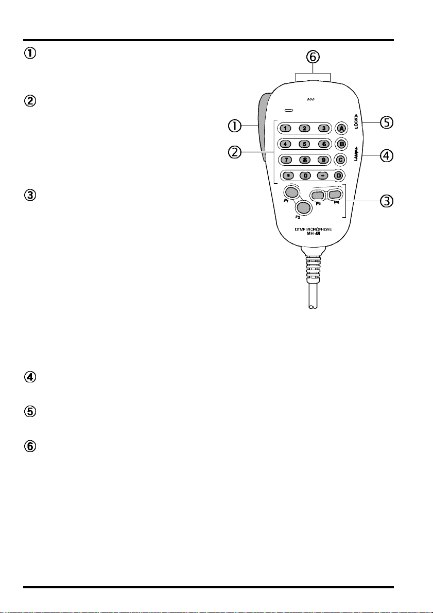
MH-48A6J MICROPHONE
PTT Switch
Press this switch to transmit, and release it
to receive.
Keypad
These 16 keys generate DTMF tones during transmission.
In the receive mode, these 16 keys can be
used for direct frequency entry and/or direct numeric recall of the Memory channels.
[P1]/[P2]/[P3]/[P4]
[P1]
button:This button replicates the functions of
the transceiver’s [BAND] key. In the European version, press this button to
transmit a 1750 Hz Burst Tone for repeater
access.
[P2]
button:This button replicates the functions of the
transceiver’s [V/M] key.
[P3]
button:This button replicates the functions of the
transceiver’s [TONE] key.
[P4]
button:This button replicates the functions of the transceiver [LOW] key.
You can reprogram the [P1], [P2], [P3], and [P4] buttons for other functions, if desired.
See page 43.
Buttons
LAMP Switch
This switch illuminate the MH-48A6J keypad.
LOCK Switch
This switch locks out the MH-48A6J buttons (except keypad and PTT switch).
UP/DWN Button
Press (or hold in) either of these buttons to tune (or scan up or down) the band or
through the memory channels. In many ways, these buttons emulate the function of the
(rotary) Main Dial knob.
16 FT-7100M Operating Manual
Page 19

MH-42B6JS MICROPHONE
The MH-42B6JS is similar to the MH-48A6J, but the MH-42B6JS does not include a DTMF
keypad and its illumination switch.
PTT Switch
Press this switch to transmit, and release it
to receive.
[
ACC]/[P]/[P1]/[P2] Buttons
[
ACC] button:This button replicates the
functions of the transceiver’s [BAND] key. In the
European version, press this
button to transmit a 1750 Hz
Burst Tone for repeater access.
[P]
button: This button replicates the functions
of the transceiver’s [V/M] key.
[P1]
button: This button replicates the functions
of the transceiver’s [TONE] key.
[P2]
button: This button replicates the functions
of the transceiver [LOW] key.
You can reprogram the [ACC], [P], [P1], and [P2
buttons for other functions, if desired. See page 43.
]
LOCK Switch
This switch locks out the MH-42B6JS buttons (except PTT switch).
UP/DWN Button
Press (or hold in) either of these buttons to tune (or scan up or down) the band or
through the memory channels. In many ways, these buttons emulate the function of the
(rotary) Main Dial knob.
Notice
If you replace the mocrophone from the MH-48A6J to MH-42B6JS or vice versa, perfome
Menu # 17 (
MIC
). See page 52 for details.
17FT-7100M Operating Manual
Page 20

OPERATION
BASIC OPERA TION/RECEPTION
Turning the Power On/Off
To turn the radio on, press and hold in the PWR switch for 1/2 second.
To turn the radio off, again press and hold in the PWR switch for 1/2 second.
Adjusting the Volume and Squelch
Volume and Squelch are set independently for the “main” and “sub” bands of the transceiver.
The upper VOL and SQL controls provide adjustment for the upper display side (MAIN
Band) of the FT-7100M, while the lower VOL and SQL controls provide adjustment for the
Lower display side (SUB Band).
Advance the setting of the appropriate VOL control for a comfortable listening level on the
back-ground noise or signals present on the band of interest.
When no signal is present, advance the SQL control of each band just to the point where the
background noise is just silenced. The Green BUSY indicator for the current band will
disappear when the background noise is silenced.
Do not advance the setting of the SQL control too far, as you will only be able to hear very
strong local signals if the squelch is set too “tight.” Leaving the squelch just past the
threshold of noise silencing results in the best sensitivity.
RF Squelch
A special RF Squelch feature is provided on the FT-7100M. This feature allows you to set
the squelch so that only signals exceeding a certain S-meter level will open the squelch. To
set up the RF Squelch circuit for operation, use the following procedure:
1. Press and hold in the [BAND] key for 1/2 second to activate the “Menu” mode.
2. Rotate the Main Dial knob to select Menu # 24 (
3. Press the [BAND] key momentarily to enable changing of this Menu item.
4. Rotate the Main Dial knob to select the desired signal strength level for the squelch
threshold (
5. Press and hold in the [BAND] key for 1/2 second to save the new setting and exit to
normal operation.
6. Finally, rotate the SQL control to the 3-o’clock position.
This adjustment can be set independently for each band.
S-1, S-5, S-9
, or
S-FULL
). The default setting is
RF SQL
).
OFF
.
18 FT-7100M Operating Manual
Page 21

OPERATION
BASIC OPERA TION/RECEPTION
Frequency Display and Band Change
If the transceiver has not been used before, the display will
look something like this:
We call the upper frequency the “main” band, and the lower
frequency the “sub” band. Transmission is possible only on
the “main” band, but you can select both bands to receive
different frequencies on the same band (V-V or U-U operation, described later).
To change the “main” band between VHF and UHF, simply
press the [BAND] key momentarily (default: “main” band is
VHF, “sub” band is UHF).
Main Dial Tuning
This mode is used for choosing a frequency within the “main” band.
In the “VFO” mode, the Main Dial knob and microphone [UP]/[DWN] buttons allow the
Variable Frequency Oscillator (VFO) to tune in the selected step size. When scanning in the
VFO mode, the same step sizes are used as in manual tuning.
To select the 1 MHz range in which you wish to operate, press the [MHz] key momentarily,
then rotate the Main Dial knob. All the “MHz” digits of the frequency display will blink
while “1 MHz Tuning” is enabled. Press the [MHz] key again (momentarily), then rotate the
Main Dial knob to tune around the “main” band in the normal synthesizer step.
USA Version
European Version
To select the 10 MHz range in which you wish to operate (if you are making a major frequency
change, for example), press and hold in the [MHz] key for 1/2 second, then rotate the Main
Dial knob. The 10 MHz and 100 MHz digits of the frequency display will blink while “10 MHz
Tuning” is enabled. Press and hold in the [MHz] key again (for more than 1/2 second), then
rotate the Main Dial knob to tune around the “main” band in the normal synthesizer step.
Direct Keypad Frequency Entry (Requires MH-48A6J)
The desired operating frequency may be entered directly from the microphone’s keypad.
To enter a frequency from the keypad, just press the numbered digits on the keypad in the
proper sequence. To round all digits to the right of the current digit to “0,” press the [#] key.
Example:
To enter 146.520 MHz, press [1] à [4] à [6] à [5] à [2] à [0].
To enter 433.000 MHz, press [4] à [3] à [3] à [#].
19FT-7100M Operating Manual
Page 22

OPERATION
BASIC OPERA TION/RECEPTION
Channel Step Selection
Tuning steps are factory preset to default increments which are appropriate for the country
to which this radio is exported. Different steps may be present for VHF and UHF, as well, if
appropriate for your area. For example, on the U.S. version, the default steps for VHF are 5
kHz, while on UHF the default steps are 25 kHz.
To change to another step size, use the following procedure:
1. Press and hold in the [BAND] key for 1/2 second to activate the “Menu” mode.
2. Rotate the Main Dial knob to select Menu # 27 (
3. Press the [BAND] key momentarily to enable changing of this Menu item.
4. Rotate the Main Dial knob to select a desired step size. The available steps are
10.0/12.5/15.0/20.0/25.0/50.0
5. Press and hold in the [BAND] key for 1/2 second to save the new setting and exit to
normal operation.
The step size can be set independently for each band. Just change the frequency band on
the “main” display field before entering Menu #27, then use the above procedure.
(kHz/step).
VFO Tracking
The “main” and “sub” VFOs may be “slaved” together, so that rotation of the Main Dial
knob (or stepping of the microphone [UP]/[DWN] buttons) causes both VFOs to move in
tandem. Each VFO will increment in the step sizes that have been established by you previously, i.e. one step on VHF might be 5 kHz and one step on UHF might be 25 kHz, and VFOs
will advance by those increments during VFO Tracking operation.
STEP
).
5.0
/
To activate VFO tracking, use the following procedure:
1. Press and hold in the [BAND] key for 1/2 second to activate the “Menu” mode.
2. Rotate the Main Dial knob to select Menu # 33 (
3. Press the [BAND] key momentarily to enable changing of this Menu item.
4. Rotate the Main Dial knob to select “ON.”
5. Press and hold in the [BAND] key for 1/2 second to save the new setting and exit to
normal operation.
To disable the VFO tracking function, select “
VFOTR
OFF
” in step 4 above.
).
20 FT-7100M Operating Manual
Page 23

OPERATION
BASIC OPERA TION/RECEPTION
Receiver Muting
The Mute feature is useful in situations where it would be helpful to reduce the audio level
of the “sub” receiver whenever you receive a signal on the “main” band.
To activate the Mute feature:
1. Press and hold in the [BAND] key for 1/2 second to activate the “Menu” mode.
2. Rotate the Main Dial knob to select Menu # 18 (
3. Press the [BAND] key momentarily to enable changing of this Menu item.
4. Rotate the Main Dial knob to select “ON.”
5. Press and hold in the [BAND] key for 1/2 second to save the new setting and exit to
normal operation.
MUTE
).
To disable the Mute feature, select “
OFF
” in step 4 above.
VHF-VHF (V-V) or UHF-UHF (U-U) Operation
The FT-7100M typically operates on one VHF and one UHF frequency. However, the FT7100M may be configured to operate either in a V-V or U-U mode, if needed. Operation in
either of these modes is easily enabled:
If the “main” band is VHF, press and hold in the [HOME
r
key for 1/2 second. The transceiver will now display replicate its VHF frequency on both upper and lower chan-
nels, and will be operating in the “V-V” mode.
If the “main” band is UHF, press and hold in the [HOME
r
key for 1/2 second. The transceiver will now replicate its
UHF frequency on both upper and lower channels, and
will be operating in the “U-U” mode.
To return to “normal” VHF-UHF operation, press and hold
r
in the [HOME] key for 1/2 second. The original VFO or
Memory frequency for the “sub” band will be restored.
During V-V or U-U operation, receive sensitivity and intermodulation rejection of the “sub”
receiver will be degraded slightly. However, this usually will not be noticeable except during
operation in highly RF-congested areas.
]
VHF-VHF (V-V) Operation
]
UHF-UHF (U-U) Operation
21FT-7100M Operating Manual
Page 24

OPERATION
BASIC OPERA TION/RECEPTION
Lock Feature
The Lock function prevents accidental changes to the frequency setting and the key/button controls.
1. Press and hold in the [BAND] key for 1/2 second to activate the “Menu” mode.
2. Rotate the Main Dial knob to select Menu # 15 (
3. Press the [BAND] key momentarily to enable changing of this Menu item.
4. Rotate the Main Dial knob one click to change the display to “ON.”
5. Press and hold in the [BAND] key for 1/2 second to save the new setting and exit to
normal operation.
LOCK
).
Lock Feature Active
To unlock the keys and buttons for normal operation, select “
OFF
” in step 4 above.
Keypad Beeper
The key/button beeper provides useful audible feedback whenever a key or button is pressed.
If you want to turn the beeper off (or back on again):
1. Press and hold in the [BAND] key for 1/2 second to activate the “Menu” mode.
2. Rotate the Main Dial knob to select Menu # 4 (
3. Press the [BAND] key momentarily to enable changing of this Menu item.
4. Rotate the Main Dial knob to select “
5. Press and hold in the [BAND] key for 1/2 second to save the new setting and exit to
normal operation.
OFF
BEEP
).
.”
Display Brightness
The orange display illumination has been specially engineered to provide high visibility over
a wide range of ambient lighting situations.
The brightness of the display is manually adjustable, using the following procedure:
1. Press and hold in the [BAND] key for 1/2 second to activate the “Menu” mode.
2. Rotate the Main Dial knob to select Menu # 7 (
3. Press the [BAND] key momentarily to enable changing of this Menu item.
4. Rotate the Main Dial knob to select a comfortable brightness level (
OFF
).
5. Press and hold in the [BAND] key for 1/2 second to save the new setting and exit to
normal operation.
DIM
).
DIM 1
~
DIM 7
, or
22 FT-7100M Operating Manual
Page 25

OPERATION
TRANSMISSION
To transmit, simply close the PTT (Push To Talk) switch on the microphone when the
frequency is clear. Hold the microphone approximately 25 mm (1”) from your mouth, and
speak into the microphone in a normal voice level. When your transmission is complete,
release the PTT switch; the transceiver will revert to the receive mode.
During transmission, the “main” band BUSY/TX indicator changes from Green to Red, and
the S&PO meter segments rise up according to the power output selected.
Power Output Setting
Four power output levels are available on this transceiver: 5 watts (LOW), 10 watts (MID 2),
20 watts (MID 1) and 50 watts (VHF) or 35 watts (UHF) on HIGH.
To change the power level, press the [LOW] key. Each time you press the [LOW] key, the
new power level will be displayed for a few seconds, then the regular display mode will
reappear.
The power level can be set independently for each band. Also, the power level may be stored
in a memory register, if desired.
PTT Locking
The PTT circuitry may be locked out, so as to prevent unauthorized or otherwise undesired transmission.
To lock out the PTT circuitry and thus prevent transmission:
1. Press and hold in the [BAND] key for 1/2 second to acti-
vate the “Menu” mode.
2. Rotate the Main Dial knob to select Menu # 16 (
3. Press the [BAND] key momentarily to enable changing of this Menu item.
4. Rotate the Main Dial knob to select the desired lock mode:
BAND A
BAND B
BOTH
OFF
5. Press and hold in the [BAND] key for 1/2 second to save the new setting and exit to
normal operation.
To cancel the PTT lock feature, select “
: PTT will be disabled on VHF only;
: PTT will be disabled on UHF only;
: PTT will be disabled on both the VHF and UHF bands; or
: PTT lock feature is off.
OFF
” in step 4 above.
LOCKT
).
PTT Lock Active
23FT-7100M Operating Manual
Page 26

OPERATION
TRANSMISSION
Repeater Splits
This transceiver offers three methods of setting up split frequency operation on repeaters:
Automatic Repeater Shift (ARS), providing automatic activation of repeater shifts during
¦
designated repeater frequency subbands;
Independently stored transmit and receive frequencies (typically not corresponding to
¦
established repeater frequency shifts); and
Manual selection of preset repeater shifts.
¦
Automatic Repeater Shift (ARS)
The ARS (Automatic Repeater Shift) feature in the FT-7100M allows easy and convenient
repeater operation by automatically activating the repeater shift function whenever you tune
within a standard repeater sub-band. The ARS function is
preset at the factory to conform to the band-plans for the
country to which it is exported.
The ARS function is enabled at the factory. To disable it:
1. Press and hold the [BAND] key for 1/2 second to activate the “Menu” mode.
2. Rotate the Main Dial knob to select Menu # 2 (
3. Press the [BAND] key momentarily to enable changing of this Menu item.
4. Rotate the Main Dial knob one click to change the display to “
5. Press and hold the [BAND] key for 1/2 second to save the new setting and exit to normal
operation.
ARS
).
OFF
.”
To enable the ARS function again, select “ON” in step 4 above.
The ARS function can be set independently for each band. And if you need to change the
default repeater shift (if the bandplan in your country should change, for example), the
default shift may be changed via Menu #26 (see page 53).
24 FT-7100M Operating Manual
Page 27

OPERATION
TRANSMISSION
Separate Transmit Frequency Memories
All memory channels can store independent receive and transmit frequencies; this allows
the radio to accommodate occasional non-standard offsets with greater frequency resolution than is available using the “standard” shift feature.
Here is the procedure for storing an “odd split” frequency pair into a memory. A full discussion of memory channel storage and recall is found in the “Memory Operation” section.
1. First store the receive (repeater output) frequency. In the VFO mode, turn the transceiver
to the desired receive frequency. Now, press and hold in the [V/M] key for 1/2 second.
2. Within five seconds of pressing the [V/M] key, use the Main Dial knob (or the
microphone’s [UP]/[DWN] buttons) to select the memory channel number on which you
wish to store the frequency pair.
3. Now press and hold in the [V/M] key again, to store the receive frequency into the
selected memory.
4. Next, store the transmit (repeater input) frequency. Since you are still in the VFO mode,
just tune the transceiver to the desired transmit frequency.
5. Now, press and hold in the [V/M] key for 1/2 second.
6. Within five seconds of pressing the [V/M] key, use the Main Dial knob (or the
microphone’s [UP]/[DWN] buttons) to select the same memory channel number as used
in step 2 above.
7. Press and hold in the PTT switch, then press and hold in the [V/M] key for 1/2 second
while holding the PTT switch. This will not cause transmission, but rather it will instruct
the transceiver that you are programming a separate transmit frequency into a memory.
When an “odd split” memory is recalled, when you press the PTT switch you will observe
the display changing to indicate the repeater’s uplink frequency. Note also that the display shows the “ ” icon on
the display; this indicates that an “odd” (non-standard) shift
has been stored on this channel.
Standard Repeater Shifts
If you may assign the “Repeater Shift” feature to one of the microphone’s programming
buttons (such as [P1]), you may activate the “standard” repeater shift by pressing the
programmable button assigned to this function. See page 43 for details regarding of the
microphone button’s functions.
25FT-7100M Operating Manual
Page 28

OPERATION
TRANSMISSION
Tone Squelch System
These systems allows silent monitoring until a call directed to you is received, and can offer
listening privacy on an otherwise busy channel.
CTCSS (Continuous Tone Coded Squelch System): This system superimposes a con-
¦
tinuous, subaudible (low-frequency) tone on your transmitted audio. When decoded at
the other station, this allows their squelch to open so as to receive your transmission.
Some “closed” repeaters use this to limit access, or to prevent signals intended for other
repeaters (with the same input frequency) in fringe areas from locking up the repeater.
There are 50 selectable CTCSS tones.
DCS (Digital Code Squelch): DCS operation modulates a subaudible tone according to a
¦
digital protocol (continuous 32-bit synchronous code). DCS is widely used in the commercial land-mobile industry because of its superior performance, and its 104 unique
codes offer greater tone selection than CTCSS.
To use either CTCSS or DCS, both stations must be on the same operating frequency, and
must have selected the same CTCSS tone or DCS code.
Select and activate CTCSS or DCS operation
1. Pressing the [TONE] key to select the desired tone control mode from the following:
“
ENC
¦
¦
¦
¦
¦
2. Within three seconds of releasing the [TONE] key, use
the Main Dial knob (or the microphone’s [UP]/[DWN
buttons) to select the tone frequency (when “
“
ENC/DEC
“
DCS
3. Wait a few seconds: the display will revert to its normal
status, and your new CTCSS or DCS information will be
saved.
” (Encode) appears when the CTCSS tone generator is activated for transmission only.
“
ENC/DEC
CTCSS tone squelch is activated for both TX & RX
(only signals “encoded” with the matching tone will
open the squelch; your radio will remain silent otherwise).
“ ” (CTCSS Bell Paging) appears when CTCSS Bell
Paging is activated, as described in detail later.
“
DCS
Code Squelch system (TX & RX) is active.
“
OFF
” is activated).
” (Encode & Decode) appears when the
” (Digital Code Squelch) appears when Digital
” (Tone or digital code system is disabled).
ENC
,” or “ ” is activated) or DCS code (when
CTCSS Tone Generator
CTCSS Tone Squelch
]
,”
CTCSS Bell Paging
DSC Code Squelch
26 FT-7100M Operating Manual
Page 29

OPERATION
TRANSMISSION
Tone Search Scanning
In operating situations where you don’t know the CTCSS or DCS code being used by
another station or stations, you can command the radio to listen to the incoming signal and
scan in search of the tone being used.
To scan for the tone in use:
1. Set the radio up for either CTCSS or DCS Decoder operation (see the previous discussion). In the case of CTCSS, “
“
DCS
” will appear on the display.
2. Press and hold the [BAND] key for 1/2 second, then rotate the Main Dial knob to select
Menu # 30 (
3. Press the [BAND] key to start scanning for the incoming CTCSS or DCS tone/code.
4. When the radio detects the correct tone or code, it will halt on that tone/code, and audio
will be allowed to pass. Press the [BAND] key to lock in that tone/code and exit to normal
operation.
TSRCH
) for CTCSS tone search or Menu # 9 (
CTCSS Bell Paging
Bell Paging adds an alert ringer to CTCSS tone squelch operation, for added convenience.
When you receive a call with a matching CTCSS tone, the ringer sounds to alert you to the
presence of the incoming call.
ENC/DEC
” will appear on the display; in the case of DCS,
DCS S
) for DCS code search.
To activate CTCSS Bell operation, press the [TONE] key until “ ” appears on the display. .
As before, calls without a matching CTCSS tone will be ignored. Those with a matching tone
will cause the transceiver to ring as the squelch opens while
the caller transmits. Note that other stations do not need to
have the CTCSS Bell function to call you; they can just use
standard CTCSS encoding.
When you reply to a CTCSS Bell call, you may want to turn off the Bell function, or else the
transceiver will ring every time your squelch opens.
You can store CTCSS Bell Paging as a “tone mode” in a memory, as you can do with different
CTCSS/DCS tone and encode/decode status.
1750 Hz Tone Calling (European Versions)
In the European versions of the FT-7100M, press the [P1] (MH-48A6J) or [ACC] (MH42B6JS) button on the microphone to transmit a 1750 Hz Burst Tone for repeater access.
If you own a non-European version of the FT-7100M, but plan on visiting a country which
requires a 1750 tone for repeater access, you may use menu #20 to set up the [P1] (MH-
48A6J) or [ACC] (MH-42B6JS) button for 1750 Hz Tone operation. See page 43 for details.
27FT-7100M Operating Manual
Page 30

OPERATION
TRANSMISSION
DTMF Tone Generation (MH-48A6J only)
The white keys (with numbers, letters, or the Ú/# characters printed on them) on the micro-
phone may be used for manual sending of DTMF tones for autopatch or repeater control
use. Just press the PTT switch, and hold it in, while pressing the desired keys.
DTMF Autodialer Operation
Sixteen DTMF Autodialer memories are available on the FT-7100M. These DTMF Autodialer
memories can store up to 16 digits of a telephone number for repeater autopatch or other use.
To load DTMF Autodialer memories, use following procedure:
1. Press and hold the [BAND] key for 1/2 second to activate the “Menu” mode.
2. Rotate the Main Dial knob to select Menu # 14 (
3. Press the [BAND] key momentarily to enable changing of this Menu item.
4. Rotate the Main Dial knob to select the DTMF Autodialer
memory channel number into which you wish store a telephone number (“
5. Press the [BAND] key momentarily.
6. Use the Main Dial knob (or the microphone’s [UP]/
[
DWN] buttons) to select the first digits of the telephone
number you wish to store.
7. When you have selected the correct digit, press the [LOW
key momentarily.
8. Now, use the Main Dial knob (or the microphone’s [UP]/
[
DWN] buttons) to select the second of 16 available dig-
its in the current DTMF Autodialer memory. Press the
[
LOW] key momentarily.
9. Repeat this procedure for each digit in the telephone number.
10. If you mistake an error during programming, you may press the [REV] key momentarily
as a backspace key. If you wish to erase all digits before the current one, press and hold
in the [REV] key for 1/2 second. You may now press the [TONE] key momentarily to
review your entry for accuracy.
11. When entry of all digits is complete, press the [BAND] key. This locks the DTMF string
into the current register.
12. Use the Main Dial knob (or the microphone’s [UP]/[DWN] buttons) to select another
DTMF Autodialer memory channel, and repeat the process described above, beginning
in step 4. When you are done programming all desired DTMF Autodialer memory channels, press and hold in the [BAND] key for 1/2 second to exit to normal operation.
CH-01
” ~ “
CH-16
”).
DTMFW
]
).
DTMF Autodialer Memory
DTMF Autodialer Memory
Current Digit
Telephone Number
28 FT-7100M Operating Manual
Page 31

OPERATION
TRANSMISSION
To transmit the memorized telephone number, used the following procedure:
1. Press the PTT switch to begin transmission.
2. While holding in the PTT switch, rotate the Main Dial knob to select the DTMF
Autodialer memory channel you wish to send, then press the [HOME] key. The DTMF
string will be transmitted automatically.
3. One the string begins, you may release the PTT switch, as the transmitter will be held “on
the air” until the DTMF string is completed.
The speed at which the DTMF digits are sent can be changed. Three speed levels are
available: 50 ms (20 digits per second, the default setting), 75 ms (13 digits per second), and
100 ms (10 digits per second).
To select the DTMF sending speed, use the following procedure:
1. Press and hold in the [BAND] key for 1/2 second to activate the “Menu” mode.
2. Rotate the Main Dial knob to select Menu # 13 (
3. Press the [BAND] key momentarily to enable changing of this Menu item.
4. Rotate the Main Dial knob to select the desired speed (“
5. Press and hold the [BAND] key for 1/2 second to save the new setting and exit normal
operation.
You can also set a longer delay between the time the [HOME] key is pressed and the first
DTMF digit is send.
DTMFS
50ms
).
,” “
75ms
,” or “
100ms
”).
To set the delay time, use the following procedure:
1. Press and hold the [BAND] key for 1/2 second to activate the “Menu” mode.
2. Rotate the Main Dial knob to select Menu # 12 (
3. Press the [BAND] key momentarily to enable changing of this Menu item.
4. Rotate the Main Dial knob to select the desired speed from the available choices
(“
50ms
,” “
250ms
5. Press and hold in the [BAND] key for 1/2 second to save the new setting and exit normal
operation.
Do not attempt to utilize the DTMF features, either manually or Auto-dialing,
while you are driving. Always park you car before dialing, in the interest of safety
to you, your passengers, and other drivers.
,” “
450ms
,” “
750ms
Important Note
,” or “
DTMFD
1000ms
).
”).
29FT-7100M Operating Manual
Page 32

OPERATION
TRANSMISSION
Transmitter Time-Out Timer (TOT)
The “Time-Out Timer” (TOT) feature is designed to force the transceiver into the “receive”
mode after a preset time period of continuous transmission (the default is 6 minutes). This
feature prevents your transceiver from transmitting a “dead carrier” for a long period of time
in the event that the microphone PTT switch is accidentally locked in the “TX” condition.
The Time-Out Timer’s “switch-to-receive” time may be adjusted, in one minute increments,
for any period between 1 and 30 minutes. To change the default (6 minutes) time setting:
1. Press and hold in the [BAND] key for 1/2 second to activate the “Menu” mode.
2. Rotate the Main Dial knob to select Menu # 31 (
3. Press the [BAND] key momentarily to enable changing of this Menu item.
4. Rotate the Main Dial knob to select the desired time interval (between 1 and
minutes, or “
5. Press and hold in the [BAND] key for 1/2 second to save the new setting and exit to
normal operation.
When the TOT feature is activated, “ ” appears at the bottom of the display, and a timer
starts every time you press the PTT switch. About a minute before the selected time-out
period has expired (during transmission), “ ” will begin blinking. Then, if you continue
pressing the PTT switch until the selected TOT time interval, transmission will case, and
you will hear the alert beeper sound until you release the PTT switch.
OFF
.”
TOT
).
60
30 FT-7100M Operating Manual
Page 33

MEMOR Y OPERATION
MEMORY STORAGE
1. Select the desired frequency, while operating in the VFO mode. Be sure to set up any
CTCSS or DCS tones as well as any desired repeater offset. The power level may also be
set at this time, if you wish to store it at a particular level of interest.
2. Press and hold in the [V/M] key for 1/2 second.
3. Within the three seconds of releasing the [V/M] key, use
the Main Dial knob (or the microphone’s [UP]/[DWN
buttons) to select the desired memory channel. The memory
channel number will blinking on the LCD.
4. To attach an alpha/numeric name (label) to the memory, press the [V/M] key momen-
tarily; otherwise press and hold in the [V/M] key for 1/2 second to save the entry and
exit.
5. To label a memory with an alpha/numeric name, use the Main Dial knob (or the
microphone’s [UP]/[DWN] buttons) to select any of the 80 available characters (including letters, numbers, and special symbols). When the desired first character appears,
press the [LOW] key momentarily to move on to the next character.
6. Select succeeding characters in the same manner, pressing the [LOW] key momentarily
after each selection.
7. You may move to the back character by pressing the [BAND] key momentarily. Press and
hold the [BAND] key for 1/2 second to erase the charactors at the right.
8. After entering the entire name (five characters maximum for upper display filed, six for
lower field), press and hold in the [V/M] key for 1/2 second to save all data for the channel
and exit.
Memory Channel Number
]
Storing Independent Transmit Frequencies (“Odd Splits”)
All memories can store an independent transmit frequency, for operation on repeaters with
non-standard shifts. Both frequencies must be inside the same amateur band. To do this:
1. Store the receiving frequency (and label the channel with an alpha/numeric name, if
desired) using the method already described under “Memory Storage” (it does not
matter if a repeater offset is active).
2. Tune to the desired transmit frequency, then press and hold in the [V/M] key for 1/2
second.
3. Within the three seconds of releasing the [V/M] key, rotate the Main Dial knob (or press
the microphone’s [UP]/[DWN] buttons) to select the same memory channel number as
used in step 1 above.
4. Press and hold in the PTT switch; while holding it in, press and hold in the [V/M] key for
1/2 second once more (this does not key the transmitter).
31FT-7100M Operating Manual
Page 34

MEMOR Y OPERATION
RECALLING MEMORIES
From the VFO mode, momentarily press the [V/M] key to activate the “Memory” mode.
When more than one memory has been stored, use the Main Dial knob to select a memory
for operation. Alternatively, the microphone’s [UP]/[DWN] buttons may be used to select or
scan through the available memories. When using the microphone’s [UP]/[DWN] buttons,
press the button momentarily to move one step up or down; press and hold the [UP] or
[
DWN] button for 1/2 second to begin memory scanning.
When you recall a memory which contains independentlystored transmit and receive frequencies, the “ ” indication will appear in the display.
If you recall a memory which includes an alpha/numeric name,
press and hold in the [LOW] key for 1/2 second to display
the alpha/numeric tag. Repeatedly pressing and holding in
the [LOW] key will toggle operation between the “Fre-
quency” display and “Tag” display options.
To return to the VFO mode, just press the [V/M] key again.
“Odd Split” memory
“Tag” Display
Direct Keypad Memory Recall (Requires MH-48A6J)
The desired memory channel may be recalled directly from the microphone’s keypad.
To recall a memory channel from the keypad, just press the digits on the keypad in the proper
sequence, followed by the
Example:
To recall memory channel #5, press [5] à
To recall memory channel #100, press [1] à [0] à [0] à
[Ú]
key.
[Ú]
.
[Ú]
.
32 FT-7100M Operating Manual
Page 35

MEMOR Y OPERATION
RECALLING MEMORIES
Memory Offset Tuning
Once you have recalled a particular memory channel, you may easily tune off that channel, as
though you were in the “VFO” mode.
1. With the FT-7100M in the “MR” (Memory Recall) mode, select the desired memory
channel.
2. Now press the [MHz] key momentarily; the “ ” icon will appear on the display. .
3. Rotate the Main Dial knob (or press the microphone’s
[UP]/[
DWN] buttons), as desired, to tune to a new fre-
quency. The synthesizer steps selected for VFO operation on the current band will be the steps used during
Memory Tuning.
4. If you wish to return to the original memory frequency, press the [V/M] key momentarily.
The “ ” icon will disappear..
5. If you wish to store the new frequency set during Memory Tuning, just press and hold in
the [V/M] key for 1/2 second, select a new memory (if desired), then press and hold in the
[
V/M] key for 1/2 second again.
MASKING A MEMORY
There may be situations where you want to “Mask” memories so they are not visible during
memory selection or scanning. For example, several memories used only in a city you visit
infrequently may be stored, then “Masked” until you visit that city, at which time you can
“Unmask” them for normal use.
1. Press and hold the [V/M] key for 1/2 second.
2. Rotate the Main Dial knob (or press the microphone’s [UP]/[DWN] buttons) to select
the memory channel to be “Masked” from view.
3. Press the [REV] key momentarily. The display will revert to memory channel #1, and the
previously-selected memory will now be “Masked.”
4. To unmask the hidden memory, repeat the above procedure: press and hold in the [V/M
key for 1/2 second, select the masked memory’s number, then press the [REV] key momentarily to restore the memory channel’s data.
If you over-write a “masked” memory channel, the original contents of the memory
will be lost.
33FT-7100M Operating Manual
]
Page 36

MEMOR Y OPERATION
TRANSFERRING MEMORY CHANNELS
There are 262 programmable memory channels in the FT-7100M. These consist of 120
regular memories and 11 special-purpose memories (L1 - L5, U1 - U5, and HOME) for each
band. However, if you need more memories on a particular band, you can transfer (regular)
memories from one group to another, as needed (such as VHF: 190 channels, UHF: 50 channels).
To transfer memory channels from one band to the other:
1. Press and hold in the [BAND] key while turning the transceiver on.
2. The display will show the present memory channel ratio.
Rotate the Main Dial knob to select the memory channel
ratio you need.
3. Press and hold in the [BAND] key for 1/2 second to save
the new setting and exit to normal operation.
Previously-stored channel data is lost when performing this procedure.
VHF Memory Channel
UHF Memory Channel
MEMORY ONLY MODE
Once memory channel programming has been completed, you may place the radio in a
“Memory Only” mode, whereby VFO operation is impossible. This may be particularly useful during public-service events where a number of operators may be using the radio for first
time, and ultimate simplicity of channel selection is desired.
To place the radio into the Memory Only mode, turn the radio off. Now press and hold in the
[
V/M] key while turning the radio on.
To return to normal operation, repeat the above power-on procedure.
34 FT-7100M Operating Manual
Page 37

SCANNING FEATURES
SCANNING OPERATION
The FT-7100M’s microprocessor-based scanning feature allows quick scanning of the
memory channels, or sweeping of a band, looking for activity.
Before activating the scanner, make sure that the SQL control is set to silence the background noise when no signal is present. If the noise is not squelched, the transceiver will
“think” that it has found a signal, and will not scan.
Scanning may be started or stopped with the microphone’s [UP] or [DWN] button.
The following techniques are used for scanning:
1. Pressing and holding in either the [UP] or [DWN] button for 1/2 second in the VFO mode
will cause upward or downward band scanning, respectively, to begin.
2. Pressing and holding in either the [UP] or [DWN] button for 1/2 second in the Memory
mode will cause memory channel scanning toward a higher- or lower-numbered memory
channel, respectively.
3. Scanning pauses when a signal opens the squelch, and the decimal point on the display
will blink. You can choose one of two scan-resume modes (described below).
4. To halt the scan manually, the easiest way is to push the PTT switch on the microphone
momentarily (no transmission will occur while you are scanning).
5. The scan may also be halted manually by pressing the microphone’s [UP]/[DWN] but-
ton, or the front panel’s [V/M] key.
Scan-Resume Options
Two scan-resume modes are available on the FT-7100M:
In the BUSY mode, the scanner will remain stopped for as long as there is a carrier
¦
present on the channel; after the carrier drops at the end of the other station’s
transmission, the scanner will resume.
In the TIME mode, the scanner will halt for five seconds only, after which scan-
¦
ning will resume (whether or not the other station is still transmitting).
To change the scan-resume mode, use the following procedure:
1. Press and hold in the [BAND] key for 1/2 second to activate the “Menu” mode.
2. Rotate the Main Dial knob to select Menu # 25 (
3. Press the [BAND] key momentarily to enable changing of this Menu item.
4. Rotate the Main Dial knob to select the desired scan-resume mode (
TIME
).
5. Press and hold in the [BAND] key for 1/2 second to save the new setting and exit
to normal operation.
SCAN
).
BUSY
or
35FT-7100M Operating Manual
Page 38

SCANNING FEATURES
MEMORY SKIP SCANNING
When you have some continuously-active channels in memories, you may wish to skip them
for scanning, but still have them available for manual selection using the Main Dial.
To mark a memory to be skipped during scanning, use the following procedure:
1. Recall the memory channel to be skipped.
Note: Memory Channel “1” may not be skipped.
2. Press and hold in the [TONE] key for 1/2 second. A small
“p” icon will appear to the bottom of the memory channel number, indicating it is to be ignored during scanning.
3. To re-enable a “skipped” memory channel, repeat the
above procedure: recall the skipped memory channel using the Main Dial, then press
and hold in the [TONE] key for 1/2 second to re-enable the channel.
Temporary Memory Skip
If the scanner repeatedly stops on a channel due to temporary noise or interference, you can
temporarily mark it to be skipped (except for Memory Channel “1”). The channel will be
skipped until you manually stop the scan (by pressing the PTT switch, for example).
To skip a channel temporarily, press the [TONE] key momentarily while the scanner has
stopped on the channel to be skipped. The scanner will instantaneously resume, and that
channel will not be scanned during this scanning session.
36 FT-7100M Operating Manual
Page 39

SCANNING FEATURES
PROGRAMMABLE BAND-SCAN LIMITS
This feature allows you to set sub-band limits for either scanning or manual VFO operation.
For example, you might wish to set up a limit (in North America) of 144.300 MHz to 148.00
MHz so as to prevent encroachment into the SSB/CW “Weak Signal” portion of the band
below 144.300 MHz. Here’s how to do this:
1. Set the radio to the VFO mode by pressing the [V/M] key, if necessary.
2. Using the techniques learned earlier, store (per above example) 144.300 MHz into Memory
Channel “L1” (the “L” designates the Lower sub-band limit).
3. Likewise, store 148.000 MHz into Memory Channel “U1” (the “U” designates the U pper
sub-band limit).
4. Switch to the Memory Recall mode by pressing the [V/M] key once, then recall Memory
Channel “L1” or “U1.”
5. Press the [MHz] key momentarily; the “ ” icon will appear on the display. .
6. You may now rotate the Main Dial knob, or begin scanning by press and holding in the
microphone’s [UP]/[DWN] button for 1/2 second. The transceiver will behave as though
it is in the standard VFO mode, but operation will be restricted to the range between
Memory channels “L1” and “U1.”
Five pairs of Band Limit memories, labeled “L1/U1” through “L5/U5,” are available. You
therefore can set a number of operating sub-bands, if you like.
37FT-7100M Operating Manual
Page 40

SCANNING FEATURES
PRIORITY C HANNEL OPERATION
The Priority function allows automatic checking for activity on a designated “Priority”
Memory channel every five second while operating on the VFO, a HOME channel, or another Memory channel.
VFO Priority
1. Recall the memory channel which you want to use as the “Priority” frequency.
2. Now set the FT-7100M for operation on any VFO frequency on the same band as the
Priority frequency.
3. Press and hold in the [REV] key for 1/2 second to activate the VFO Priority mode; the
“PRI” icon will appear on the display. The frequency display will remain on the VFO
frequency, but every five seconds the FT-7100M will check the Priority Channel (designated memory channel) for activity.
4. Press the [V/M] key to disable the VFO Priority mode and exit to the VFO mode.
Memory Priority
1. Store the frequency you wish to use as the “Priority” channel into memory channel “1.”
2. Now set the FT-7100M for operation on another memory channel on the same band as
the Priority channel .
3. Press and hold in the [REV] key for 1/2 second to activate the Memory Priority mode; the
“PRI” icon will appear on the display. The frequency display will remain on the current
memory channel frequency, but every five seconds the FT-7100M will check the Priority
channel (memory channel “1”) for activity.
4. Press the [V/M] key to disable the Memory Priority mode and exit to the memory mode.
HOME Priority
1. Recall the memory channel which you wish to use as the “priority” frequency.
2. Now set the FT-7100M for operation on the HOME channel that is on the same band as
the selected HOME channel.
3. Press and hold in the [REV] key for 1/2 second to activate the HOME Priority mode; the
“PRI” icon will appear on the display. The frequency display will remain on the HOME
channel frequency, but every five seconds the FT-7100M will check the Priority channel
(memory channel) for activity.
4. Press the [V/M] key to disable the HOME Priority mode and exit to the HOME channel.
38 FT-7100M Operating Manual
Page 41

SMART SEARCH
The Smart Search feature may be used to load - automatically with no operator intervention
- a special bank of up to 50 memory channels (per band) based on activity. Smart Search will
sweep either the entire band or the portion of the band within the Programmable Band-Scan
Limits, and will load the Smart Search memory bank with the frequency data pertaining to
those channels on which activity is found. The channels are loaded in the order in which
they are encountered, not according to signal strength or by ascending frequency.
The Smart Search feature is especially useful when visiting a city for the first time, where you
may be unfamiliar with the repeater frequencies used locally; Smart Search discovers where
the local activity is to be found, and automatically loads those frequencies for you.
Smart Search operation is simple to activate:
1. Press and hold in the [TONE] key for 1/2 second.
2. The Smart Search process will now cause the radio to scan upward on the current band,
loading channels on which it encounters a signal strong enough to open the squelch.
3. When 50 channels are loaded or the scanner reaches the band edge, the scanner will stop
and the transceiver will revert to the starting frequency.
4. To recall the Smart Search Memories just stored, rotate the Main Dial knob.
5. Press the [V/M] key momentarily to exit the Smart Search mode.
Note that these memories are so-called “soft” memories; they will be lost if you exit Smart
Search to a VFO/Memory, or if you initiate a new Smart Search. Smart Search also does not
store CTCSS or DCS information; if you cannot access a repeater found during Smart Search,
you may need to investigate possible access tones.
39FT-7100M Operating Manual
Page 42

,” or “
:
AUTO RANGE TRANSPONDER SYSTEM
ARTS IN
ARTS IN
OFF
.” The operating descriptions assume that both radios are set to “
ARTS OUT
” will appear on the display. Whether you talk or not, the
”.
ARTS
).
ARTS OUT
” will appear continuously; otherwise “
.” After two pollings (one minute), if a response is
ARTS IN
OFF
” in step 4 above.
RANGE
” will be
ARTS
ALL
ARTS
This system uses DCS signaling to inform you when you and another ARTS-equipped
station are within communications range. Both stations must first select DCS operation
using the same DCS code.
Whenever you press the PTT switch, or every 30 seconds after ARTS is activated, your
radio will transmit a (subaudible) DCS signal. If the other radio is in range, the beeper (if
enabled) will sound and “
radios will continue to poll each other every 30 seconds while ARTS is activated.
You can also have your radio transmit your callsign via CW every ten minutes, to comply
with identification requirements.
If either station moves out range for more than one minute (two polls), your radio will sense
that no signal has been received. A beep will sound, and the display will change to “
OUT
” (out of range). If you move back into range, your radio will again beep, and the display
will change back “
During ARTS operation, the microprocessor makes it impossible to change the operating
frequency or other settings; you must first terminate ARTS to resume normal operation. This
is a safety feature to prevent accidental loss of contact due to channel change, etc.
Here is how to activate ARTS:
1. Press and hold in the [BAND] key for 1/2 second to activate the “Menu” mode.
2. Rotate the Main Dial knob to select Menu # 3 (
3. Press the [BAND] key momentarily to enable changing of this Menu item.
4. Rotate the Main Dial knob to select the desired ARTS operating mode: “
“
ALL
5. Press and hold in the [BAND] key for 1/2 second to save the new setting and exit. The
display will now show “
not detected, “
displayed as long as both stations remain in range.
6. To cancel ARTS operation, select “
,”
.”
ARTS Modes
RANGE
ALL
OFF
:A high tone beep will sound when the transceiver first detects that you are
within range, and a low beep will sound when the other station goes out of
range.
: A high tone beep will sound every time a polling transmission is received
from the other station, and a low beep will sound once when the other
station goes out of range.
: ARTS operation is disabled.
40 FT-7100M Operating Manual
Page 43

ARTS
:
AUTO RANGE TRANSPONDER SYSTEM
CW ID (Morse Identifier) Set up
The ARTS feature includes a CW identifier, as mentioned previously. The radio can be
instructed to send “DE (your callsign) K” in Morse code every nine minutes during ARTS
operation. The callsign may contain up to 6 characters.
Here’s how to program the CW Ider:
1. Press and hold in the [BAND] key for 1/2 second to activate the “Menu” mode.
2. Rotate the Main Dial knob to select Menu # 6 (
3. Press the [BAND] key momentarily to enable programming of your callsign.
4. You will notice the first character’s entry slot blinking. While it is blinking, rotate the
Main Dial knob to select the desired character, then press the [LOW] key to move on to
the next character to the right.
5. Rotate the Main Dial knob to select the next number or letter, then press the [LOW] key
to move on the next character.
6. You may move to the back character by pressing the [BAND] key momentarily. Press and
hold the [BAND] key for 1/2 second to erase the charactors at the right.
7. When the callsign is complete, press and hold in the [BAND] key for 1/2 second to save
the CW ID entry and exit to normal operation.
To activate the CW Ider for use during ARTS operation:
1. Press and hold in the [BAND] key for 1/2 second to activate the “Menu” mode.
2. Rotate the Main Dial knob to select Menu #5 (
3. Press the [BAND] key momentarily to enable changing of this Menu item.
4. Rotate the Main Dial knob to change the display to “ON.”
5. Press and hold in the [BAND] key for 1/2 second to save the new setting and exit to
normal operation.
6. To disable the CW IDer, select “
OFF
” in step 4 above.
CWIDW
CWID
).
).
41FT-7100M Operating Manual
Page 44

MISCELLANEOUS SETTINGS
SUB-DISPLAY OPTIONS
The Sub-Display can be set to one of four modes using the Menu.
1. Press and hold in the [BAND] key for 1/2 second to activate the “Menu” mode.
2. Rotate the Main Dial knob to select Menu #11 (
3. Press the [BAND] key momentarily to enable changing of the Menu item.
4. Rotate the Main Dial knob to select the new setting. The options include:
DC IN
: Displays and monitors the battery or DC power supply voltage.
CW ID
: Displays the CW ID (your call sign).
FREQ
: Displays the “sub” band frequency.
OFF
: Turns off the Sub-Display.
Note: When this Menu selection is set to “
5. Press and hold in the [BAND] key for 1/2 second to save the new display configuration
and exit to normal operation.
A UTOMATIC POWER-OFF
The “Automatic Power-Off” (APO) feature will turn the radio completely off after a userdefined period of PTT or key/button inactivity. If you do not press any front panel keys or
buttons, do not rotate the Main Dial knob, do not use the microphone’s keys and buttons,
do not transmit, and so long as the transceiver is not scanning or engaged in priority
monitoring, the radio will shut itself off after the specified time period. This feature is useful
in minimizing battery drain in a mobile installation if you forget to turn the transceiver off
when you leave your vehicle.
DISP
).
OFF
,” the sub band receiver will be disabled.
To activate the APO feature:
1. Press and hold in the [BAND] key for 1/2 second to activate the “Menu” mode.
2. Rotate the Main Dial knob to select Menu #1 (
3. Press the [BAND] key momentarily to enable changing of the Menu item.
4. Rotate the Main Dial knob to select the desired “switch-off” time (between
hours (0.5 hour steps), or
5. Press and hold in the [BAND] key for 1/2 second to save the new APO setting and exit to
normal operation.
When the APO feature is activated, “ ” appears at the left of the frequency on the
display, and a timer starts every time you press a key. If you don’t press the any keys until
about three minutes before the end of the selected power-down period, as long as you are
not scanning or priority monitoring, “ ” will begin blinking and an alert beeper will
sound. If you don’t press a key in the next three minutes, the transceiver will turn itself off.
OFF
).
APO
).
0.5
and
12
42 FT-7100M Operating Manual
Page 45

MISCELLANEOUS SETTINGS
PROGRAMMING THE MICROPHONE BUTTON FUNCTIONS
Default FT-7100M button functions have been assigned (at the factory) to the microphone’s
buttons*. These may be changed by the user, if you wish to define another function for a
particular button or buttons
To change the assignment of a button’s function:
1. Press and hold in the [BAND] key for 1/2 second to activate the “Menu” mode.
2. Rotate the Main Dial knob to select the
Menu item corresponding to the button
to be assigned a function (20:
21:
PG P2
, 22:
PG P3
, or 23:
PG P1
PG P4
3. Press the [BAND] key momentarily to enable changing of the selected Menu item.
4. Rotate the Main Dial knob to select the function you wish to assign to the button you
selected in the previous step. The available choices are:
SQL OFF
TCALL
RPTR
PRI
LOW
TONE
MHz
REV
HOME
BAND
VFO/MR
: Disables (opens) the Noise and Tone Squelch.
: Activates 1750 Hz Tone Burst.
: Selects Repeater Shift Direction.
: Activates Priority Channel monitoring.
: Selects Power Output Level.
: Selects CTCSS or DCS mode and tone/code.
: Enables selection of the “MHz” digit of the frequency.
: Reverses Repeater Uplink/Downlink frequencies.
: Switches frequency to the “Home” channel.
: Selects “main” band of operation: VHF or UHF.
: Switches frequency control between VFO and Memory.
5. Press and hold in the [BAND] key for 1/2 second to save the new setting(s) and exit to
normal operation.
).
,
MENU ITEM
20:
PG P1
21:
PG P2
22:
PG P3
23:
PG P4
MH-48A6J LABEL
[P1]
button
[P2]
button
[P3]
button
[P4]
button
MH-42B6JS LABEL
[
ACC] button
[P]
button
[P1]
button
[P2]
button
*: MH-48A6J: [P1], [P2], [P3], and [P4] buttons.
MH-42B6JS: [ACC], [P], [P1], and [P2] buttons.
43FT-7100M Operating Manual
Page 46

MISCELLANEOUS SETTINGS
DCS CODE INVERSION
The DCS system was first introduced in the commercial LMR (Land Mobile Radio) service,
where it is now in widespread use.
DCS uses a codeword consisting of a 23-bit frame, transmitted (subaudibly) at a data rate of
134.4 bps (bit/sec). Occasionally, signal inversion can result in the complement of a code
being sent or received. This prevents the receiver squelch from opening with DCS enabled,
as the decoded bit sequence would not match that selected for operation. Typical situations
that might cause inversion to occur are:
Connection of an external receiver preamplifier.
¦
Operating through a repeater.
¦
Connection of an external linear amplifier.
¦
Note that code inversion does not mean that any of the above listed equipment is defective!
In certain amplifier configurations, the output signal (phase) is inverted from the input. Small
signal or power amplifiers having an odd number (1, 3, 5, etc.) of amplification stages may
result in inversion of a transmitted or received DCS code.
While under most circumstances this should not occur (amplifier designs and industry
standards take this into account), if you find that your receiver squelch does not open when
both you and the other station are using a common DCS code, you or the other station (but
not both) can try the following:
1. Press and hold in the [BAND] key for 1/2 second to activate the “Menu” mode.
2. Rotate the Main Dial knob to select Menu #10 (
3. Press the [BAND] key momentarily to enable changing of the Menu item.
4. Rotate the Main Dial knob to select one of the following modes:
TRX N
: Encoder Normal; Decoder Normal
RX R
: Encoder Normal; Decoder Reverse (Inverted)
TX R
: Encoder Reverse (Inverted); Decoder Normal
TRX R
: Encoder Reverse (Inverted); Decoder Reverse (Inverted)
5. Press and hold in the [BAND] key for 1/2 second to save the new setting and exit to
normal operation.
DCSNR
)
44 FT-7100M Operating Manual
Page 47

MISCELLANEOUS SETTINGS
EXTERNAL SPEAKER SELECTION
You can select the audio output configuration for the speakers when an external speaker is
connected to the EXT SP jack on the rear panel.
To select the speaker to be used on a particular band:
1. Press and hold in the [BAND] key for 1/2 second to activate the “Menu” mode.
2. Rotate the Main Dial knob to select Menu #28 (
3. Press the [BAND] key momentarily to enable changing of this Menu item.
4. Rotate the Main Dial knob to select the new setting. The options include:
BAND A
BAND B
BOTH
OFF
5. Press and hold in the [BAND] key for 1/2 second to save the new configuration and exit
to normal operation.
: Directs VHF band audio to the external speaker, and UHF band audio to the
internal speaker. During V-V operation (VHF) audio from the upper frequency
display field on the LCD is sent to the external speaker, while (VHF) audio
from the lower frequency display field on the LCD is sent to the internal
speaker. Conversely, during U-U operation, upper-display-field UHF audio
is sent to the internal speaker, and lower-display-field UHF audio is sent to
the external speaker.
: Directs UHF band audio to the external speaker, and VHF band audio to the
internal speaker. During V-V operation (VHF) audio from the upper frequency
display field on the LCD is sent to the internal speaker, while (VHF) audio
from the lower frequency display field on the LCD is sent to the external
speaker. Conversely, during U-U operation, upper-display-field UHF audio
is sent to the external speaker, and lower-display-field UHF audio is sent to
the internal speaker.
: Outputs both VHF and UHF band audio from the external speaker, and turns
off the internal speaker.
: Turns off the external speaker, and outputs both VHF and UHF band audio
from the internal speaker.
SPCNT
).
Some or all transceiver settings can be reset to their factory-default states using one of the
following power-on routines:
45FT-7100M Operating Manual
Page 48

MICROPROCESSOR RESET PROCEDURES
r Reset for All Memories
Press and hold in the [V/M] and [REV] keys while turning the transceiver on.
r Reset for Menu Settings (except following menu)
Press and hold in the [LOW] and [REV] keys while turning the transceiver on.
Menu #8 (
r CPU Master Reset for All Memories and Menu Settings
Press and hold in the [V/M], [MHz], and [REV] keys while turning the transceiver on.
DCS C
), 19 (
PCKT
), 26 (
SHIFT
), 27 (
STEP
), 29 (
TONEF
)
46 FT-7100M Operating Manual
Page 49

CLONING
You can transfer all data stored in one FT-7100M to another FT-7100M by utilizing the
handy “Cloning” feature. This requires a user-constructed Cloning cable which connects
the DATA jacks on the two transceivers, as shown below.
To clone from one transceiver to another, use the following procedure:
1. Insert the Clone Cable into the DATA jack of each transceiver.
2. Turn both transceivers off, then press and hold in the [REV] and [TONE] keys (on each
radio) while turning the power on again.
3. On the “destination” radio, press the [REV] key. The “
on the display.
4. Now, on the “source” radio, press the [TONE] key. The “
appear on the display, and the cloning data transfer will immediately begin.
5. If there is a problem during the cloning process, “
cable connections, and try again.
6. If cloning was successful, the “
7. Turn both transceivers off, then remove the Clone Cable. Channel and operating data for
both radios are now identical. They both may be turned on now for normal operation.
CLONE RX
” and “
CLONE RX
ERROR
” will be displayed. Check your
CLONE TX
” indicator will appear
CLONE TX
” indicator will disappear.
” indicator will
47FT-7100M Operating Manual
Page 50

MENU SYSTEM
The FT-7100M’s Menu System allows a number of transceiver operating parameters to be
custom-configured for your operating requirements.
The Menu is easy to active and set, using the following basic procedure:
1. Press and hold in the [BAND] key for 1/2 second to activate the “Menu” mode.
2. Rotate the Main Dial knob to select the Menu item to be adjusted.
3. Press the [BAND] key momentarily to enable changing of the selected Menu item.
4. Rotate the Main Dial knob to adjust or select the desired parameter of the selected
Menu item.
5. After completing your adjustment(s), press and hold in the [BAND] key for 1/2 second to
save the new setting(s) and exit to normal operation.
48 FT-7100M Operating Manual
Page 51

Item #
Menu Item
1
APO
Enables/disables the Automatic Power
2
3
ARTS
4
BEEP
5
CWID
6
CWIDW
7
8
DCS C
9
DCS S
10
DCSNR
11
12
DTMFD
13
DTMFS
14
DTMFW
15
LOCK
16
LOCKT
17
18
MUTE
19
PCKT
20
PG P1
21
PG P2
22
PG P3
23
PG P4
24
RFSQL
25
SCAN
26
SHIFT
27
STEP
28
SPCNT
29
TONEF
30
TSRCH
31
32
TXNAR
33
VFOTR
34
ø : Depens on transceiver version
Off feature
ARS
Enables/disables the Automatic Re-
peater Shift function
Selects the ARTS mode
Enables/disables the key/button beeper
Enables/disables the CW IDer during
ARTS operation
Programming a callsign into the CW IDer
DIM
Setting the front panel display’s illumina-
tion level
Setting the DCS code number
Activates the DCS Code Search
Scanner
Selects “Normal” or “Inverted” DCS
coding
DISP
Selects the “sub” band display format
Setting the DTMF Autodialer delay time
Setting the DTMF Autodialer sending
speed
Loading of DTMF Autodial memory
register(s)
Enables/disables the key/button lock
Enables/disables the PTT switch lock
MIC
Selects the Microphone type to be used
Reduces the audio level on the sub
receiver when the main receiver is
active
Setts the transceiver’s circuitry for the
Packet baud rate to be used
Programming the microphone’s
[P1]/[
ACC] button assignment
Programming the microphone’s [P2]/[P
button assignment
Programming the microphone’s [P3]/[P1
button assignment
Programming the microphone’s [P4]/[P2
button assignment
Adjusts the RF SQL threshold level
Selects the Scan-Resume mode
Sets the magnitude of the Repeater Shift
Setting the synthesizer steps
Defining the audio path to the external
speaker (when used)
Setting the CTCSS Tone Frequency
Activates the CTCSS Tone Search
Scanner
TOT
Sets the Time-Out Timer
Reducing the MIC Gain (and Deviation)
Enables/disables the VFO Tracking
feature
AM
Selects the receiving mode (VHF band)
Function
MENU SYSTEM
Available Values
OFF/0.5 ~ 12.0 hours
ON/OFF
RANGE/ALL/OFF
ON/OFF
ON/OFF
OFF/DIM 1 ~ DIM 7
104 standard DCS codes
TRX N/RX R/TX R/TRX R
FREQ/OFF/DC IN/CW ID
50/250/450/750/1000 ms
BAND A/BAND B/BOTH/
]
]
]
S-1/S-5/S-9/S-FULL/OFF
5.0/10.0/12.5/15.0/20.0/
BAND A/BAND B/BOTH/
50 standard CTCSS Tones
OFF/1 ~ 30 minutes
–
–
50/75/100 ms
–
ON/OFF
OFF
MH-42/MH-48
ON/OFF
1200/9600 bps
SQL OFF,
TCALL, RPTR,
PRI, LOW,
TONE, MHz,
REV, HOME,
BAND, VFO/MR
BUSY/TIME
0.00 ~ 99.50 MHz
25.0/50.0 kHz
OFF
–
ON/OFF
ON/OFF
AUTO/INH/AM
Default
OFF
ON
OFF
ON
OFF
–
DIM 1
023
–
TRX N
FREQ
450 ms
50 ms
–
OFF
OFF
ø
OFF
1200 bps
ø
VFO/MR
TONE
LOW
OFF
BUSY
ø
ø
BOTH
100 Hz
–
6 minutes
OFF
OFF
AUTO
49FT-7100M Operating Manual
Page 52

MENU SYSTEM
MENU SELECTION DETAILS
Menu Item 1 [APO
Function: Enables/disables the Automatic Power Off feature.
Available Values: 0.5 ~ 12.0 hours (0.5 hour steps), or OFF
Default Setting: OFF
]
Menu Item 2 [ARS
Function: Enables/disables the Automatic Repeater Shift function.
Available Values: ON/OFF
Default Setting: ON
Note: This Menu item can be set independently for each band.
Menu Item 3 [ARTS
Function: Selects the ARTS mode.
Available Values: RANGE/ALL/OFF
Default Setting: OFF
Note: This Menu item can be set independently for each band.
Menu Item 4 [BEEP
Function: Enables/disables the key/button beeper.
Available Values: ON/OFF
Default Setting: ON
Menu Item 5 [CWID
Function: Enables/disables the CW IDer during ARTS operation.
Available Values: ON/OFF
Default Setting: OFF
Menu Item 6 [CWIDW
Function: Programming a callsign into the CW IDer.
Menu Item 7 [DIM
Function: Setting the front panel display’s illumination level.
Available Values: DIM1 ~ DIM7, or OFF
Default Setting: DIM1 (Brightest illumination)
]
]
]
]
]
]
50 FT-7100M Operating Manual
Page 53

MENU SYSTEM
MENU SELECTION DETAILS
Menu Item 8 [DCS C
Function: Setting the DCS code number.
Available Values: 104 standard DCS codes
Default Setting: 023
Note: This Menu item can be set independently for each band, and independently in
each memory.
Menu Item 9 [DCS S
Function: Activates the DCS Code Search
Scanner.
Menu Item 10 [DCSNR
Function: Selects “Normal” or “Inverted” DCS coding.
Available Values: TRX N/RX R/TX R/TRX R
Default Setting: TRX N
Note 1: This Menu item can be set independently for each band.
Note 2: “N” is “normal,” “R” is “inverted.”
]
023 025 026 031 032 036 043 047 051 053
054 065 071 072 073 074 114 115 116 122
125 131 132 134 143 145 152 155 156 162
165 172 174 205 212 223 225 226 243 244
245 246 251 252 255 261 263 265 266 271
274 306 311 315 325 331 332 343 346 351
356 364 365 371 411 412 413 423 431 432
]
445 446 452 454 455 462 464 465 466 503
506 516 523 526 532 546 565 606 612 624
627 631 632 654 662 664 703 712 723 731
732 734 743 754 – – – – – –
]
DCS CODE
Menu Item 11 [DISP
]
Function: Selects the “sub” band display format.
Available Values: FREQ/OFF/DC IN/CW ID
Default Setting: FREQ
FREQ: Displays the “sub” band frequency.
OFF: No display.
DC IN: Displays the DC supply voltage.
CW ID: Displays the CW ID while the ATRS feature is activated.
Note: When this Menu selection is set to “OFF,” the sub band receiver will be disabled.
Menu Item 12 [DTMFD
]
Function: Setting the DTMF Autodialer delay time.
Available Values: 50/250/450/750/1000 ms
Default Setting: 450 ms
Menu Item 13 [DTMFS
]
Function: Setting the DTMF Autodialer sending speed.
Available Values: 50/75/100 ms
Default Setting: 50 ms (High Speed)
51FT-7100M Operating Manual
Page 54

MENU SYSTEM
MENU SELECTION DETAILS
Menu Item 14 [DTMFW
Function: Loading of DTMF Autodial memory register(s).
]
Menu Item 15 [LOCK
Function: Enables/disables the key/button lock.
Available Values: ON/OFF
Default Setting: OFF
Menu Item 16 [LOCKT
Function: Enables/disables the PTT switch lock.
Available Values: BAND A/BAND B/BOTH/OFF
Default Setting: OFF
Note: “BAND A” is “VHF,” “BAND B” is “UHF.”
Menu Item 17 [MIC
Function: Selects the Microphone type to be used.
Available Values: MH-42/MH-48
Default Setting: Depends on transceiver version.
Menu Item 18 [MUTE
Function: Reduces the audio level on the sub receiver when the main receiver is active.
Available Values: ON/OFF
Default Setting: OFF
Menu Item 19 [PCKT
Function: Sets the transceiver’s circuitry for the Packet baud rate to be used.
Available Values: 1200/9600 bps
Default Setting: 1200 bps
Note: This Menu item can be set independently for each band.
]
]
]
]
]
Menu Item 20 [PG P1
Function: Programming the microphone’s [P1]/[ACC] button assignment.
Available Values: SQL OFF, TCALL, RPTR, PRI, LOW, TONE, MHz, REV, HOME, BAND,
VFO/MR
Default Setting: USA version; BAND, European version; TCALL
Note: [P1] button for MH-48 A6J, [ACC] button for MH-42 B6SJ
]
52 FT-7100M Operating Manual
Page 55

MENU SYSTEM
MENU SELECTION DETAILS
Menu Item 21 [PG P2
Function: Programming the microphone’s [P2]/[P] button assignment.
Available Values: SQL OFF, TCALL, RPTR, PRI, LOW, TONE, MHz, REV, HOME, BAND,
VFO/MR
Default Setting: VFO/MR
Note: [P2] button for MH-48A6J, [P] button for MH-42B6SJ
]
Menu Item 1 [PG P3
Function: Programming the microphone’s [P3]/[P1] button assignment.
Available Values: SQL OFF, TCALL, RPTR, PRI, LOW, TONE, MHz, REV, HOME, BAND,
VFO/MR
Default Setting: TONE
Note: [P3] button for MH-48A6J, [P1] button for MH-42 B6SJ
Menu Item 23 [PG P4
Function: Programming the microphone’s [P4]/[P2] button assignment.
Available Values: SQL OFF, TCALL, RPTR, PRI, LOW, TONE, MHz, REV, HOME, BAND,
VFO/MR
Default Setting: LOW
Note: [P4] button for MH-48A6J, [P2] button for MH-42 B6SJ
Menu Item 24 [RFSQL
Function: Adjusts the RF SQL threshold level.
Available Values: S-1/S-5/S-9/S-FULL/OFF
Default Setting: OFF
Note: This Menu item can be set independently for each band.
Menu Item 25 [SCAN
Function: Selects the Scan-Resume mode.
Available Values: BUSY/TIME
Default Setting: BUSY
Note: This Menu item can be set independently for each band.
]
]
]
]
Menu Item 26 [SHIFT
Function: Sets the magnitude of the Repeater Shift.
Available Values: 0.00 ~ 99.50 MHz (50 kHz step)
Default Setting: Depends on transceiver version.
Note: This Menu item can be set independently for each band.
]
53FT-7100M Operating Manual
Page 56

MENU SYSTEM
MENU SELECTION DETAILS
Menu Item 27 [STEP
Function: Setting the synthesizer steps.
Available Values: 5.0/10.0/12.5/15.0/20.0/25.0/50.0 kHz
Default Setting: Depends on transceiver version.
Note: This Menu item can be set independently for each band.
]
Menu Item 28 [SPCNT
]
Function: Defining the audio path to the external speaker (when used).
Available Values: BAND A/BAND B/BOTH/OFF
Default Setting: BOTH
Note: BAND A: VHF Audio
During V-V operatin, audio from “upper” VHF frequency on the LCD.
During U-U operatin, audio from “lower” UHF frequency on the LCD.
BAND B: UHF Audio
During V-V operatin, audio from “lower” VHF frequency on the LCD.
During U-U operatin, audio from “upper” UHF frequency on the LCD.
BOTH: VHF and UHF audio are both routed to external speaker (internal speaker
is off)
OFF: All audio is routed to internal speaker (external speaker is off).
Menu Item 29 [TONEF
Function: Setting the CTCSS Tone Frequency.
Available Values: 50 Standard CTCSS Tones
Default Setting: 100 Hz
Note: This Menu item can be set independently
for each band, and independently in each
memory.
Menu Item 30 [TSRCH
Function: Activates the CTCSS Tone Search
]
]
CTCSS TONE FREQUENCY (Hz
67.0 69.3 71.9 74.4 77.0 79.7
82.5 85.4 88.5 91.5 94.8 97.4
100.0 103.5 107.2 110.9 114.8 118.8
123.0 127.3 131.8 136.5 141.3 146.2
151.4 156.7 159.8 162.2 165.5 167.9
171.3 173.8 177.3 179.9 183.5 186.2
189.9 192.8 196.6 199.5 203.5 206.5
210.7 218.1 225.7 229.1 233.6 241.8
250.3 254.1 – – – –
Scanner.
)
Menu Item 31 [TOT
]
Function: Sets the Time-Out Timer.
Available Values: 1 ~ 30 minutes, or OFF
Default Setting: 6 minutes
54 FT-7100M Operating Manual
Page 57

MENU SYSTEM
MENU SELECTION DETAILS
Menu Item 32 [TXNAR
Function: Reducing the MIC Gain (and Deviation)
Available Values: ON/OFF
Default Setting: OFF (Normal Deviation)
Note: This Menu item can be set independently for each band.
]
Menu Item 33 [VFOTR
Function: Enables/disables the VFO Tracking feature.
Available Values: ON/OFF
Default Setting: OFF
Menu Item 34 [AM
Function: Selects the receiving mode on the VHF band.
Available Values: AUTO/INH/AM
Default Setting: AUTO (AM in Aeronautical Bands, FM elsewhere)
Note: The “INH” option locks reception in the FM mode.
]
]
55FT-7100M Operating Manual
Page 58

NOTE
56 FT-7100M Operating Manual
Page 59

1. Changes or modifications to this device not expressly approved by VERTEX
STANDARD could void the user’s authorization to operate this device.
2. This device complies with part 15 of the FCC Rules. Operation is subject to
the following two conditions; (1) this device may not cause harmful
interference, and (2) this device must accept any interference including
interference that may cause undesired operation.
3. The scanning receiver in this equipment is incapable of tuning, or readily
being altered, by the User to operate within the frequency bands allocated
to the Domestic public Cellular Telecommunications Service in Part 22.
This device complies with RSS-210 of Industry Canada. Operation is subject
to the following two conditions; (1) this device may not cause interference, and
(2) this device must accept any interference, including interference that may
cause undesirable operation of the device.
WARNING: MODIFICATION OF THIS DEVICE TO RECEIVE CELLULAR
RADIOTELEPHONE SERVICE SIGNALS IS PROHIBITED UNDER FCC RULES
AND FEDERAL LAW.
Page 60

Copyright 2001
VERTEX STANDARD CO., LTD.
All rights reserved.
Printed in Japan
No portion of this manual
may be reproduced
without the permission of
VERTEX STANDARD CO., LTD.
0103u-CY
E H 0 0 3 M 1 0 1
 Loading...