

Yaesu FT-65R, FT-65E Operating Manual
144/430 MHz
DUAL BAND TRANSCEIVER
FT-65R
FT-65E
Operating Manual

Contents
General Description ............................................ 1
Features of the FT-65R/E ................................1
About this manual ............................................ 2
Downloading the “Advance Manual” ............... 3
Accessories & Options ....................................... 4
Supplied Accessories ...................................... 4
Available Options.............................................4
Safety Precautions .............................................. 5
Control & Connections (Top & Front Panel) ...10
Controls & Connections (Side Panel) .............. 11
Controls & Connections (LCD) ......................... 12
Normal operation display ............................... 12
The Set Mode and Preference Mode display 12
Display of features and settings .................... 13
Controls & Connections (Keypad) ................... 14
Installation of Accessories ............................... 15
Antenna Installation ....................................... 15
Preparation of SBR-25LI Battery Pack .......... 15
Installing the Battery Pack ....................... 15
Removing the Battery Pack ..................... 16
Attaching the Belt Clip ................................... 16
Charging the Battery Pack................................ 17
About Desktop charger lamp ........................ 17
Low Battery Indication ................................... 18
About Battery Indicator Icons .................. 18
Approximate Operating Time and Remaining
Charge Level Indication........................... 18
Basic Operation ................................................. 19
Turn the Power ON and OFF ........................19
Adjust the Audio Volume Level and Squelch
Setting ........................................................... 19
Changing between VFO mode and Memory
mode ............................................................. 19
Selecting the Operating Band ....................... 19
Frequency Navigation ................................... 20
1) Tuning Frequency ............................... 20
2) Direct Keypad Frequency Entry .......... 20
3) Scanning ............................................. 20
Transmission .................................................21
Changing the Transmit Power Level .......21
Activating the Set Mode ................................ 22
Setting the Quick Recall Keys ....................... 22
Assigning Set Mode Items to the Quick
Recall Keys (Set Mode Recall feature) ... 22
Storing the displayed Frequency and
Settings to a Quick Recall Key (Quick
Memory feature) ...................................... 23
Setting the Preferred Operating Mode .......... 23
Advanced Operation ......................................... 24
Turning the Keylock Feature ON and OFF .... 24
Change the key locking scheme ............. 24
Change the LCD and keypad back light setting ..
...................................................................... 24
Disabling the Keypad and Scan Stop Beeper 25
Repeater Operation ........................................... 26
Repeater Shifts .............................................. 26
Automatic Repeater Shift (ARS) .................... 26
Manual Repeater Shift Setting ...................... 27
Tone Calling (1750 Hz) ..................................28
Memory Mode .................................................... 29
Memory Storage ............................................ 30
Memory Recall .............................................. 31
Changing the memory label (tag) name ........ 31
HOME Channel Memory Recall .................... 32
Changing the Home Channel Frequency 32
Memory Offset Tuning ...................................32
Deleting Memories ........................................ 33
Weather Broadcast Channels ....................... 34
Severe Weather Alert .............................. 34
Scanning ............................................................ 35
Setting the Scan-Resume Technique ......35
VFO Scanning ............................................... 36
Manual VFO Scan ................................... 36
Programmed Mode (VFO) Scan.............. 36
Input Character/Symbol List ............................. 38
Set (Menu) Mode ................................................ 39
Troubleshooting ................................................43
The transceiver does not turn on............. 43
There is no sound.................................... 43
There is no transmission of radio waves. 43
The keys or DIAL do not respond. ...........43
The battery pack cannot be charged or
battery power depletes immediately after
charging................................................... 44
Specifications .................................................... 45
General.................................................... 45
Transmitter ..............................................45
Receiver .................................................. 46
“AUTO” Mode Preset Operating Parameter .... 46
USA Version ............................................46
Asian/European Version ..........................46
FT-65R/FT-65E Operating Manual

General Description
Features of the FT-65R/E
FT-65R/E is a dual band FM transceiver, ruggedly constructed to meet com-
mercial specications. It is packed with the following popular and valuable
features demanded by Amateur Radio operators around the world.
Long-Life Battery
Supplied 7.4 V 1,950 mAh lithium ion battery.
Optional 7.4 V 2,500 mAh lithium ion battery.
5 Watts of Reliable RF Power
RF Power Output 5.0 W (High) / 2.5 W (Middle) / 0.5 W (Low) (@7.4 V)
Four Quick Recall Keys (User Programmable) for Individual Preferences
Set Mode Recall feature and Quick Memory Feature.
Powerful Audio
Bridged Transless (BTL) amplier provides One Full Watt of Audio for
operation in noisy environments.
Rugged Body Construction
IP54 Rating and MIL-STD-810-C, D, E certied.
Lockout Capabilities
Keypad/PTT Lockout.
Emergency Features
Emergency Operation (Alarm, SOS Flash and HOME channel display),
LED Flash light equipped.
FM Radio Broadcast Receiver Feature
1FT-65R/FT-65E Operating Manual
General Description
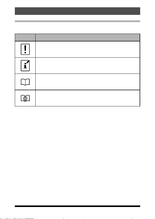
About this manual
This manual contains symbols and conventions to call attention to important
information.
Symbols Description
This icon indicates cautions and alerts the user should be
aware of.
This icon indicates helpful notes, tips and information.
This icon indicates other pages containing relevant information.
This icon refers users to the FT-65R/E Advance Manual on
the YAESU Website containing relevant information.
• The settings of the transceiver at the time of purchase are referred to as the
“default” or “default setting”.
• The names of Set Mode items that are displayed on the LCD, and the
transceiver key names, are printed in bold characters in this manual.
2
FT-65R/FT-65E Operating Manual
General Description
Downloading the “Advance Manual”
The Advance Manual provides detail information and features beyond the
scope and descriptions in this manual. Download the FT-65R/E Advance
Manual from the YAESU website and refer to it along with this Operating
Manual.
http://www.yaesu.com/
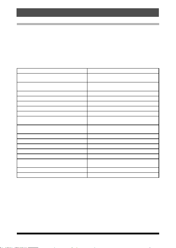
The features described in the FT-65R/E Advance Manual are below.
RF Squelch Emergency Channel Operation
Checking the Battery Voltage ARTS™ (Automatic Range Transponder
VOX Operation (with earpiece microphone
or External Mic)
VFO Split Mode DTMF Operation
Using the Squelch Feature Miscellaneous Settings
Selecting the Squelch Type Password
Setting CTCSS Tone frequency Changing the Channel Steps
Setting DCS CODE number TX Battery Saver
CTCSS/DCS/PAGER/ARTS™ Bell Opera
tion
EPCS (Enhanced Paging & Code
Squelch)
Memory Bank Operation Transmitter Time-Out Timer (TOT)
Memory Only Mode Busy Channel Lock-Out (BCLO)
Scanning Changing the TX deviation Level
Memory scanning Voice Compander Feature
Weather Alert Scan Inversion Scramble (Asian version only)
Programmable (Band Limit) Memory
Scan (PMS)
“Priority Channel” Scanning Set (Menu) Mode
Automatic Lamp Illumination on Scan Stop
System)
Basic ARTS™ Setup and Operation
Disabling the TX/BUSY LED Indicator
-
Automatic Power-Off (APO) Feature
Cloning
FT-65R/FT-65E Operating Manual
3

Accessories & Options
Supplied Accessories
SBR-25LI 7.4V, 1,950 mAh
Rechargeable Li-Ion Battery Pack
SAD-20B* AC Adapter (for USA model)
SAD-20C/U* AC Adapter (for European / Asian model)
SAD-20G* AC Adapter (for Chinese model)
SBH-22 Rapid Charger
SHB-18 Belt Clip
SRA-15 Antenna
Operating Manual
Quick Manual
Warranty Card
Available Options
SBR-25LI 7.4V, 1,950 mAh
Rechargeable Li-Ion Battery Pack
SBR-26LI 7.4V, 2,500 mAh
Rechargeable Li-Ion Large-Capacity Battery Pack
SBH-22 Rapid Charger
SAD-20B* AC Adapter (for USA model)
SAD-20C/U* AC Adapter (for European / Asian model)
SAD-20G* AC Adapter (for Chinese model)
SCU-35 Programming cable
SCU-36 Cloning Cable
SSM-512B VOX Earpiece Microphone
*B: for 120 VAC, C: for 220-240 VAC, U: for 220-240 VAC w/BF plug, G: for
230 VAC
Availability of accessories may vary. Some accessories are supplied as
standard for specic local requirements, while others may be unavailable in
some regions. This product is designed to perform optimally when used with
genuine Yaesu accessories. Yaesu shall not be liable for any damage to this
product and/or accidents such as re, leakage or explosion of a battery pack,
etc., caused by the malfunction of non-Yaesu accessories. Consult your Yae
su dealer for details regarding these and any newly-available options. Connection of any non-Yaesu-approved accessory, should it cause damage, may
void the Limited Warranty on this apparatus.
-
4 FT-65R/FT-65E Operating Manual
Safety Precautions
Be sure to read the safety precautions to use this
product safely.
Yaesu is not liable for failures and other problems caused due to misuse
or use of this product by you or a third party. Also, Yaesu is not liable for
damages caused through use of this product by you or a third party except in
the case where ordered to pay for damages under the laws.
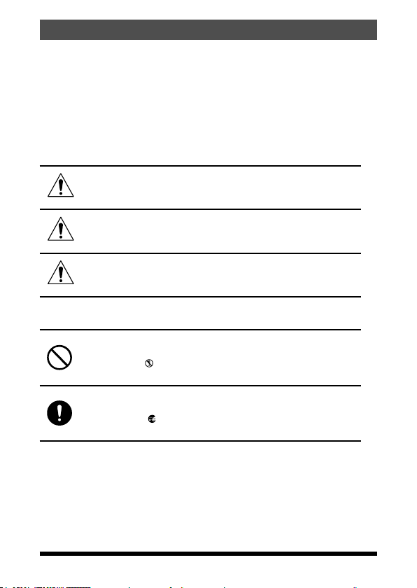
Type and meaning of the marks
Indicates an imminently hazardous situation
DANGER
WARNING
CAUTION
Type and meaning of symbols
Indicates a prohibited action, not to be done in order to use this
product safely.
For example,
sembled.
Indicates a required action, to be done in order to use this
product safely.
For example,
moved.
which, if not avoided, could result in death or
serious injury.
Indicates a potentially hazardous situation
which, if not avoided, could result in death or
serious injury.
Indicates a potentially hazardous situation
which, if not avoided, may result in minor or
moderate injury or only property damage.
indicates that the product should not be disas-
indicates that the power plug should be re-
5FT-65R/FT-65E Operating Manual
Safety Precautions
DANGER
Do not use this product in “an
area where use of it is prohib
ited”, e.g., inside the hospital,
airplane, or train.”
This product can affect electronic
or medical devices.
Do not use this product while
riding a bicycle or driving a
car. Accidents can result.
Be sure to stop the bicycle or car
at a safe place before using this
product.
Do not perform transmission
in a crowded place for the safe
ty of persons using a medical
device such as a cardiac pace
maker.
The radio wave emitted from this
product can cause the medical
device to malfunction and result
in an accident.
Do not touch any material leak
ing from the battery pack with
bare hands.
The chemical that has stuck to
your skin or entered your eye can
cause chemical burns. In such a
case, consult the doctor immedi
ately.
-
-
-
-
-
Those who are carrying a medical device such as a cardiac
pacemaker should not perform
transmission near the device.
When transmitting, use an ex
ternal antenna and keep as far
as possible away from the ex
ternal antenna.
The radio wave emitted by the
transmitter can cause the medical
device to malfunction and result in
an accident.
Do not use this product or
the battery charger in a place
where inflammable gas is gen
erated.
A fire or explosion can occur.
Do not solder or short-circuit
the terminal of the battery pack.
A fire, leak, overheating, explo
sion, or ignition can result.
Do not carry the battery pack to
gether with a necklace, hair pin, or
small metal objects.
A short circuit can result.
If it starts thundering when the
external antenna is used, imme
diately turn off this product and
disconnect the external anten
na from it.
A fire, electrical shock, or damage
may result.
-
-
-
-
-
-
-
6
FT-65R/FT-65E Operating Manual
WARNING
Do not power this transceiver
with a voltage other than the
specified power supply volt
age.
A fire, electric shock, or damage
may result.
Do not use the battery pack for
any model other than the spec
ified transceiver.
A fire, leak, overheating, explo
sion, or ignition can result.
Do not make very long trans
missions.
The main body of the transceiver
may overheat, resulting in a fail
ure or burns.
Do not disassemble or make
any alteration
to this product.
An injury, electric shock, or failure
can result.
Keep the terminals of the bat
tery pack clean.
If terminal contacts are dirty or
corroded, a fire, leak, overheat
ing, explosion, or ignition can
result.
Do not handle the battery pack
or charger with wet hands. Do
not insert or remove the power
plug with wet hands.
An injury, leak, fire, or failure can
result.
Safety Precautions
If smoke or strange odor is emitted from the main body, battery
pack, or battery charger, imme
diately turn the transceiver off;
remove the battery pack, and
remove the power plug from the
outlet.
A fire, leak, overheating, damage,
-
ignition, or failure can result. Con
tact the dealer from which you
-
purchased this product or Yaesu
Amateur Customer Support.
Do not use the battery pack
which is externally damaged or
deformed.
A fire, leak, heating, explosion, or
ignition can result.
Do not use any battery charger
which is not specified by Yaesu.
A fire or failure can result.
When transmitting, keep the
transceiver at least 5.0 mm (3/16
inch) away from your body.
-
Use only the supplied antenna.
Do not use modified or damaged
antennas.
-
If charging of the battery pack
cannot be completed within the
specified charging time, imme
diately remove the power plug
of the battery charger from the
outlet.
A fire, leak, overheating, explosion,
or ignition can result.
-
-
-
FT-65R/FT-65E Operating Manual
7
Safety Precautions
CAUTION
Do not dangle or throw this
product by holding its antenna.
This product can hit and injure
someone.
In addition, doing so can result in
a transceiver failure or damage.
Do not use transceiver in a
crowded place.
The antenna can hit someone,
resulting in a injury.
Do not place this transceiver in
a place subject to direct sun
light or near a heater.
The transceiver can deform or
discolor.
Do not place this transceiver in
a humid or dusty place.
A fire or failure can result.
During transmission, keep the
antenna as far from you as
possible.
Long-time exposure to electromagnetic waves can have a negative impact on your health.
Do not clean the case with
thinner or benzene.
Use a soft, dry cloth to clean the
case.
If the transceiver is not being
used for an extended period,
turn it off and remove the bat
tery pack for safety.
Do not drop, strike, or throw
the transceiver.
A failure or damage may result.
Keep magnetic cards and video
tape away from the transceiver.
The data recorded on cash cards
or video tape can be erased.
Charge the battery pack within
the temperature range from +5
°C to +35 °C (+41 °F to +95 °F).
Charging the battery pack outside
this temperature range can cause
leak, overheating, decrease in
performance, or reduction in ser
-
-
vice life can result.
When unplugging the power
cord of the battery charger, be
sure to hold the power plug.
Pulling the power cord can dam
age it and cause a fire or electronic shock.
Do not use the earpiece mi
crophone, earphones, or headphones at an extremely high
volume level.
Hearing impairment can result.
Keep this product out of reach
of children.
An injury, etc. can result.
Install the hand strap and belt
clip securely.
If they are installed improperly, the
FT- 65R/E may fall or drop, result
ing in an injury or damage.
-
-
-
-
8
FT-65R/FT-65E Operating Manual
CAUTION
Do not place a heavy object on
the power cord of the battery
charger.
The battery cord can be dam
aged, resulting in a fire or electric
shock.
Do not use the included battery
charger to charge any battery
pack which is not specified for
use with the charger.
A fire can result.
Do not operate the transmitter
near the TV or radio.
Radio disturbance can occur in
the transceiver, the TV, or the
radio.
Do not use any products other
than the specified options and
accessories.
A failure can result.
Safety Precautions
When the battery charger is not
-
in use, remove its power plug
from the outlet.
Before discarding the worn
battery
pack, affix tape or the like to its
terminals.
Before using this transceiver
in a hybrid or fuel-saving car,
be sure to check with the auto
mobile manufacturer regarding
use of the transceiver
in that car.
Noise generated by an onboard
electrical device (inverter, etc.)
can disrupt the normal operation
of the transceiver.
-
FT-65R/FT-65E Operating Manual
9
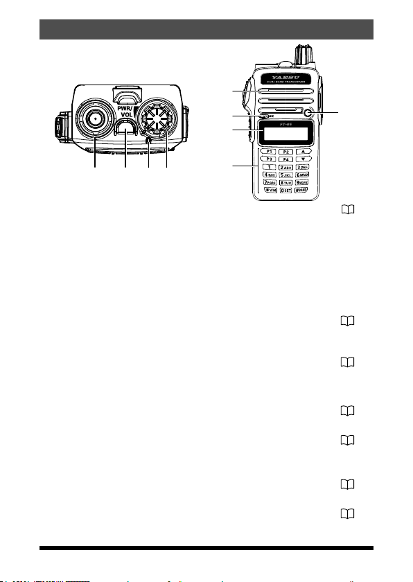
Control & Connections (Top & Front Panel)
Antenna Jack ........................................................................ 15
Connect the supplied SMA female antenna (or another antenna present-
ing a 50-Ohm impedance) here.
Emergency key
• Press this switch briey to turn the LED Flash-Light.
• Press and hold it for three seconds to enable the Emergency Alarm
beep functions.
• Press the keypad F key, and then press this switch to blink the LED
Flash-Light for SOS.
TX/BUSY Indicator Lamp
This indicator glows green when the squelch opens, and it glows red
during transmit.
PWR/VOL Knob
Turn this control clockwise to turn the transceiver ON and to increase the
volume. Counter-clockwise rotation into the click-stop will turn the trans
ceiver OFF.
Speaker
The internal speaker is located here.
Microphone
The internal microphone is located here.
LED Flash-Light
LCD (Liquid Crystal Display)
The display shows current operating condition.
Keypad
These 18 keys select the important operating functions of the FT-65R/E.
..................................................................... 19
................................................................................. 19
........................................................................... 21
.................................................................................. 14
...................................................... 19
............................................... 12
10 FT-65R/FT-65E Operating Manual
-
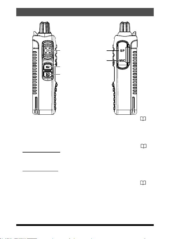
Controls & Connections (Side Panel)
PTT (Push To Talk) Switch ..................................................
• Press this switch to transmit, and release it (to receive) after your transmission is completed.
• In the Set mode, press the PTT switch to save the new setting and return
to normal operation.
MONI/T.CALL Key (Function is selectable from Set mode)
.....................................................................................................
•USA/Asian Version:
Press this switch to open the squelch, and listen for very weak signals
near the background noise level.
•European Version:
Pressing this switch activates the T-CALL (1750 Hz) for repeater access.
F key .....................................................................................
Press and hold this key to enter the Set Mode.
SP Jack
This three-conductor miniature jack provides connection for an external
speaker.
MIC Jack
This three-conductor miniature jack provides connections for microphone
audio, earphone audio, PTT, and ground.
21
28
22
11FT-65R/FT-65E Operating Manual
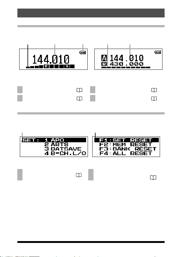
Controls & Connections (LCD)
Normal operation display
1 2 3 4
Single Display Mode (Default) Dual Display Mode
1 S & PO Meter ..................... 21 3 Battery Indicator ................ 18
2 Operating Frequency ....... 20 4 VFO-A / VFO-B ………… 23
1
The Set Mode and Preference Mode display
5
Set Mode Preferred Operating Mode
5 Set Mode Menu .................
6
Preferred Operating Mode Menu ..
22 6
.............................................
23
12 FT-65R/FT-65E Operating Manual
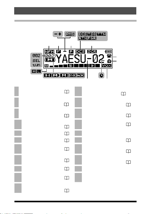
Control & Connections (LCD)
Display of features and settings
9 10 12
7 8
11
v
13
27
26
v
v
v v
14
15
25
24
23
Operating Mode ................. 19 18
7
Secondary Keypad Active ..........
8
.............................................
Repeater Shift Direction..............
9
.............................................
Programmable Memory (Mode
10
(VFO)) Scan .....................
11 Priority Channel .............. 14 22 Skipped Memory Channel
12 Squelch Operation .......... 41 23 Home Channel ..................
13 Scramble Feature* .......... 42 24
14 DTMF Mode ..................... 40 25
15 Keypad Lock .................. 24 26 Selecting ICON indicator
16 VOX Feature .................... 42 27
Automatic Power-Off Feature ..
17
..........................................
* This feature is displayed depending on the transceiver version.
2122 20
19 18 17
Memory Tag Name .....................
.......................................
Weather Channel* ......................
19
14
............................................
Memory Bank ............................
20
27
............................................ 29
21 Memory Mode ...................
36
TX Power Level Indicator .........
............................................
Memory Offset Tuning ...............
............................................
Memory (BANK) Channel Number
39
16
30,31
34
29
32
21
32
FT-65R/FT-65E Operating Manual
13
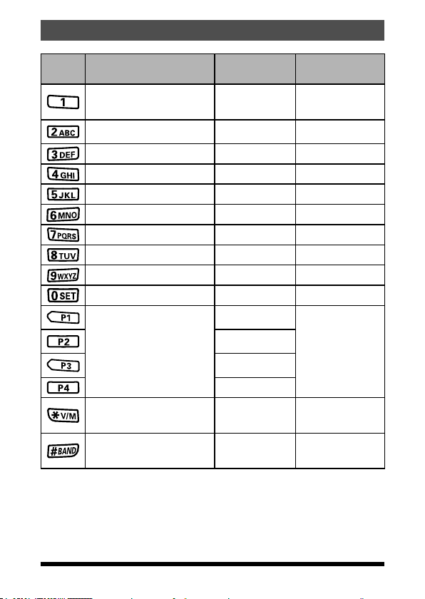
Controls & Connections (Keypad)
tion
Third Function
(Press and Hold Key)
Recalls the “Weather”
broadcast
channel bank
Activates the ARTS
feature
store or assign a
setting to the key
Memory write mode
Program Scan Setting
Key
*1 : When entering a frequency from the keypad, there is a short-cut for
frequencies ending in zero - after the last non-zero digit, press and hold
the [0/SET] key to enter all the zeros at once.
Primary Function
(PRESS Key)
Frequency entry digit “1” ―
Frequency entry digit “2” ―
Frequency entry digit “3” ― ―
Frequency entry digit “4” ― ―
Frequency entry digit “5” ― ―
Frequency entry digit “6” ― Key Lock feature
Frequency entry digit “7” ― ―
Frequency entry digit “8” ― ―
Frequency entry digit “9” ― ―
Frequency entry digit “0” ― ―*1
recall the stored or
assigned setting
Switches the frequency control
between the VFO and Memory
Systems
Switches the band control
between VHF, UHF and FM
RADIO Broadcast
Secondary Func
(PRESS F + Key)
HOME (Fixed
setting)
TX PWR (Fixed
setting)
SQL TYPE (Fixed
setting)
REV (Fixed setting)
Activates the Priori-
ty function
PMS(Program Mem-
ory (Mode) Scan)
14 FT-65R/FT-65E Operating Manual
 Loading...