

Yaesu FT-450, FT-450AT User Manual

YAESU
FT-450
FT-450AT
Users Manual
18 August 2013

Authors Message
When I started this project, I did so thinking that the Yaesu Manual was too confusing and hard to learn
from. Besides, writing a User’s Manual is a great way to learn any system.
Well, I have to say, I was wrong about the first item. It turns out the Yaesu Manual is very good. It is just
that the FT-450 is a very complex machine. I continued with the effort because my second reason is still
valid. And I wanted a shorter reference manual, structured closer to the way I think, to provide myself
with a slightly different perspective of this impressive machine.
You will find that this is structured to my machine. I do not have the enhanced microphone, a linear
amplifier to boost up the power, and as yet I do not have the software in my computer to drive RTTY ,
packet, or slow scan video.
Where Yaesu’s version of the manual gives explicit instructions on an entire task, I have tried to break it
down to functional procedures and presume that the reader will learn these basic procedures so that I do
not have to spell out the specifics of every keystroke over and over again.
The only area covered by this document that was not clear in the Yaesu manual is found in section 5.2
where I discuss the interaction between M-TUNE, VFO-A, and VFO-B.

YAESU HF/50 mHz Transceiver FT-450 User’s Manual
Table of Contents
1 General
2 Controls
2.1
3 Receiver
3.1
3.2
3.3
3.3.1 Clarifier
3.3.2
3.4
3.4.1 RF Attenuation and Intercept Point Optimization (IPO)
3.4.2 Noise Blanking
3.4.3 Digital Signal Processor
.....................................................................................................................................1
....................................................................................................................................1
Power
...............................................................................................................................3
....................................................................................................................................4
Communications Mode
Band
.................................................................................................................................4
VFO (Variable Frequency Oscillator)
...................................................................................................... 4
.................................................................................. 5
........................................................................................................................6
Split Frequency Operation
Extracting the Signal from the Noise
.............................................................................................. 6
................................................................................... 7
.................................................... 7
.............................................................................................................. 7
................................................................................................. 7
3.4.3.1
Contour
............................................................................................................ 8
3.4.3.2 Notch............................................................................................................... 8
3.4.3.3 Digital Noise Reduction (DNR)
3.4.3.4
Band Pass Width
3.4.3.5 Filter Shift
3.4.4
CW Reverse
3.4.4.6 CW Spotting
3.4.5 Radio Frequency Gain
3.4.5.7 Automatic Gain Control
3.4.5.8 Radio Frequency Volume Control
........................................................................................................ 9
.................................................................................................................. 9
............................................................................................. 8
.................................................................................................... 9
.................................................................................................... 9
................................................................................... 9
....................................................................... 8
................................................................. 10
3.4.6 Audio Volume Control.......................................................................................... 10
3.4.7 Signal meter
4 Transmitter
4.1
4.1.1 Microphone Button
4.1.2 Voice Activated Transmitter Switching (VOX)
4.1.3 CW Break-In
4.1.4 Data
4.2
4.3
5 Channel Memories
5.1
5.2
5.3
5.4
5.5
5.6
5.6.1 Recall
5.6.2 Storage
5.6.3 Removal
5.6.4 Labeling
5.7
..............................................................................................................................10
Transmission
............................................................................................................................11
Meter
..............................................................................................................................11
Automatic Antenna Tuner
Memory Content
Tuning of the VFO Setup Memory
Band VFO Setup Memory
Home Memory
Quick Memory
Channels Memories
VFO Memory Scanning
................................................................................................................ 10
................................................................................................................... 11
...................................................................................................... 11
.............................................................. 11
............................................................................................................... 11
................................................................................................ 12
................................................................................................................... 12
.............................................................................................................. 12
.................................................................................... 13
................................................................................................ 14
................................................................................................................ 14
................................................................................................................ 14
......................................................................................................... 15
.........................................................................................................................15
........................................................................................................................15
..................................................................................................................... 15
......................................................................................................................15
................................................................................................... 16
- i -

YAESU HF/50 mHz Transceiver FT-450 User’s Manual
5.8
Programmable Memory scanning
6 System Controls
6.1
Display Brightness
6.2
Semi-automatic Keyer
6.3
Custom Switch
7 Adaptation (Menu)
7.1
Transceiver function operational parameters
7.2
Tranceiver Controls
7.3
Computer Aided Transceiver (CAT) Operation
7.4
Adaptation of CW communication
7.5
Adaptation to exclude bands and modes
7.6
Adaptation for microphone
7.7
Adaptation of repeater communication
7.8
Adaptation of Data communication
7.9
Adaptation of RTTY communication
7.10 Adaptation of VOX Operation
8 Procedural Uses
8.1
CW Setup
8.2
SSB Setup
8.3
Antenna Testing
8.4
CW Training
9 Acronym Glossary
Table 1 - Controls
Table 2 – Communication Modes
Table 3 – Transceiver Bands
Table 5 – Base frequency step size for controls
Table 6 – Band Width Filter Settings
Table 7 – Memory Channel Number
Table 8 – Contents of Each Memory Channel
Table 9 – 20 Unique Assignable Button Functions
Table 10 – 8 Assignable shortcuts of F followed by an existing buttons
Table 11 – 22 Duplicate Button Functions
Table 12 – Miscellaneous redundant or useless function
Table 13 – Adaptable Parameters
Table 14 – CTCSS tone frequencies (Hz)
.......................................................................................................................16
...........................................................................................................16
......................................................................................................16
.................................................................................................................16
...................................................................................................................18
..........................................................................................................21
.......................................................................................................................25
........................................................................................................................25
........................................................................................................................26
...............................................................................................................27
....................................................................................................................27
....................................................................................................................28
...............................................................................................................................3
........................................................................................................4
...............................................................................................................5
...................................................................................................9
..................................................................................................12
......................................................................................................20
......................................................................................16
......................................................................20
..................................................................22
.....................................................................................22
.............................................................................24
...............................................................................................24
...............................................................................24
....................................................................................25
.................................................................................25
...........................................................................................25
Table of Tables
....................................................................................5
.....................................................................................13
..............................................................................17
...............................................17
..........................................................................................18
......................................................................18
...........................................................................................21
- ii -

YAESU HF/50 mHz Transceiver FT-450 User’s Manual
1 General
The Yaesu FT-450 HF/50 MHz Transceiver is designed for Amateur Radio use. It provides a
general-purpose receiver covering 30 KHz through 56 MHz. The Transceiver range is broken
into 10 Amateur Radio Bands and 1 general purpose band to cover the remaining high frequency
spectrum. The variable frequency oscillator (VFO) setup for each band is remembered
individually as you switch bands. The details of what makes up a VFO setup will be described
when we get into the section on memory. The transceiver allows communication in using side
band, continuous wave, amplitude modulation, frequency modulation, and (when computer
driven) a number of data modes.
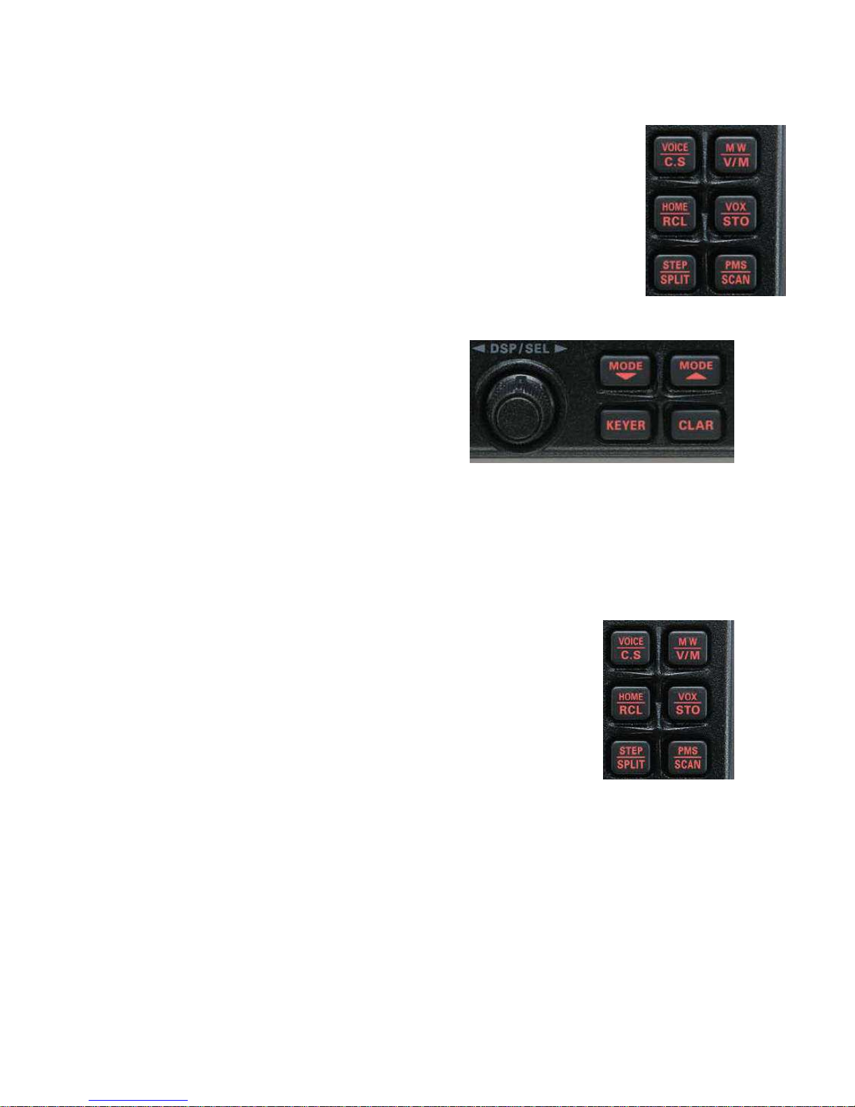
2 Controls
The FT-450 front panel contains 24 push buttons, 3 analog rotary dials, 2 rotary digital dials, a lighted
display, and three jacks. The small rotary digital dial (“DSP/SEL”) has 24 steps per revolution and also
functions as a push button. The large rotary digital dial has 100 steps per revolution. A number of push
buttons behave differently if held down for one second (adaptable).
Since there are literally hundreds of settings possible on the FT-450, a button, knob, or dial may be used
to control more than one function. The less often changed values are set by a sequence of buttons and/or
dials. For example, if you press the “F■” button (2nd from right mid height button), the letter F will
illuminate on the display. The upper right six buttons have two names on each. If the F is illuminated, the
button performs the function of the upper name and the F is extinguished. Otherwise those buttons
perform the function of the lower name.
Definitions:
f-press = press a button preceded by the “F■” button
t-press = press a button and hold for 1 second (adaptable 0.5, 1.0, 1.5, or 2.0 seconds)
- 1 -
YAESU HF/50 mHz Transceiver FT-450 User’s Manual
CONTROL ACT STATE FUNCTION
ON/OFF T-PRESS - Toggle system ON/OFF
DSP PRESS - Step DSP contour, notch, digital noise reduc, width, OFF
PRESS - Step through combinations of ATT and IPO off and on ATT/IPO
T-PRESS CW Voice tone to compare with CW tone to spot the frequency
NB PRESS - Toggles noise blanker
PRESS - Step automatic gain control through auto, fast, slow AGC
T-PRESS - Turn off automatic gain control
- Steps forward through enabled bands BAND▼ PRESS
menu Steps forward through bands to enable/disable
- Steps backward through enabled bands BAND▲ PRESS
menu Steps backward through bands to enable/disable
PRESS - Toggle enable/disable of automatic antenna tuner TUNE
T-PRESS - Start tuning to antenna process
F
T-PRESS
PRESS - Step through power, ALC, standing wave ratio meter METER/DIM
T-PRESS - Start brightness adjustment via DSP/SQL(end with press)
MODE▼
T-PRESS
MODE▲
PRESS - Steps forward through enabled modes
-menu Steps backward through modes to enable/disable
T-PRESS CW Toggles between USB and LSB reception
A=B PRESS - Copy the current VFO settings into the secondary VFO
A/B PRESS - Swap the current and secondary VFO settings
KEYER PRESS - Toggle CW keyer on/off (manual vs space assisted keying)
CLAR PRESS - Allow offset of receive frequency with “MAIN” dial
FAST PRESS - Toggle increase in frequency steps for both dials
LOCK PRESS - Lock frequency (see details) to avoid accidental change
SHIFT PRESS - Shift the intermediate frequency (IF) pass band
DSP/SEL
TURN
PRESS
MAIN DIAL TURN - Fine setting of frequency (end memory mode)
- Enter the “F■” (function) state PRESS
menu
Generates the next group of 5 practice CW characters
cwtrain
- Enter or leave the “menu” state (see section 6 adaptation)
power off Reset adaptation to factory default when turn power on
- Steps forward through enabled modes PRESS
-menu Steps forward through modes to enable/disable
CW Toggles between USB and LSB reception
power off Display software version (194) when turn power on
Small kHz steps in frequency (see Table 5) 100 KHx steps in frequency (may be adapted to set CW
side tone, CW speed, 1 mHz steps, mic gain, or rf power)
single channel steps MEMORY
single groups steps
DSP Step values for selected filter (shown by “>”)
MENU Step through list of adaptable items
MENU
Step through allowed values fore individual items
blink
- Toggle between small and large steps in frequency
MEMORY Toggle between groups and individual memory numbers
DSP Toggle type of filter on/off, sense, magnitude (see writeup)
MENU select menu item (blink menu display) for setting
- 2 -
YAESU HF/50 mHz Transceiver FT-450 User’s Manual
CONTROL ACT STATE FUNCTION
not squelch Analog setting of radio frequency gain SQL/RF GAIN TURN
squelch Analog setting of squelch level
AF GAIN TURN - Analog setting of audio frequency gain
F Announce the frequency and mode in voice to operator, VOICE/C.S PRESS
- Customer adapted function ( see Tables 9, 10, 11, 12)
MW/V/M
T-PRESS power off Clear memory channels when power turned on
HOME/RCL
STEP/SPLIT
This document was derived from the information in the Yaesu HF/50 MHz Transceiver FT-450 Operation
Manual.
PRESS
T-PRESS power on Reset adapt, clear memory channels when turn power on
T-PRESS - Activate quick SPLIT operation
F Memory write VFO setup to selected channel (1 out of 508) PRESS
- Copy memorized VFO setup into current VFO
F Copy preferred (quick) VFO setup into current VFO
- Copy quick VFO setup into current VFO
F MW Copy current VFO setup into home channel
menu blink
F Activate or deactivate voice activated transmission VOX/STO PRESS
- Copy current VFO setup into (preferred (quick) memory
F Toggle setting frequency step with DSP/SEL knob PRESS
- Toggle operation using secondary VFO settings to transmit
F Toggle program memory scan between two frequencies PMS/SCAN PRESS
- Toggle upward scanning of frequencies or memory channel
In most cases, the menu item restored to factory default
Table 1 - Controls
2.1 Power
To toggle the FT-450 transceiver ON or OFF, t-press the ON/OFF button. Some portion of
the display will show when the unit is on. Needless to say, the 12 volts must already be
supplied to the unit.
The power switch is also used to reset memory and/or adaptation in the FT-450. Warning: Do not perform
any of the first three following steps unless you are prepared to lose information:
1) Turning the power on while holding the “F■” button will restore adaptation
to the factory default settings.
2) Turning the power on while holding the “VM/V/M” button will clear all memory
channels except QMB.
3) Turning the power on while holding the “HOME/RCL” button will both
restore adaptation to the factory default settings and clear all memory channels
except QMB.
- 3 -
YAESU HF/50 mHz Transceiver FT-450 User’s Manual
4) Turning the power on while holding the “MODE▼” button will display the current software
version. You must then turn the power off and then on to resume normal operation.
3 Receiver
The transceiver provides both a multi-band sensitive receiver and transmitter. Most of the
controls have to do with the operation of the receiver section. However, Mode, Band, and VFO
apply to the transmitter section as well.
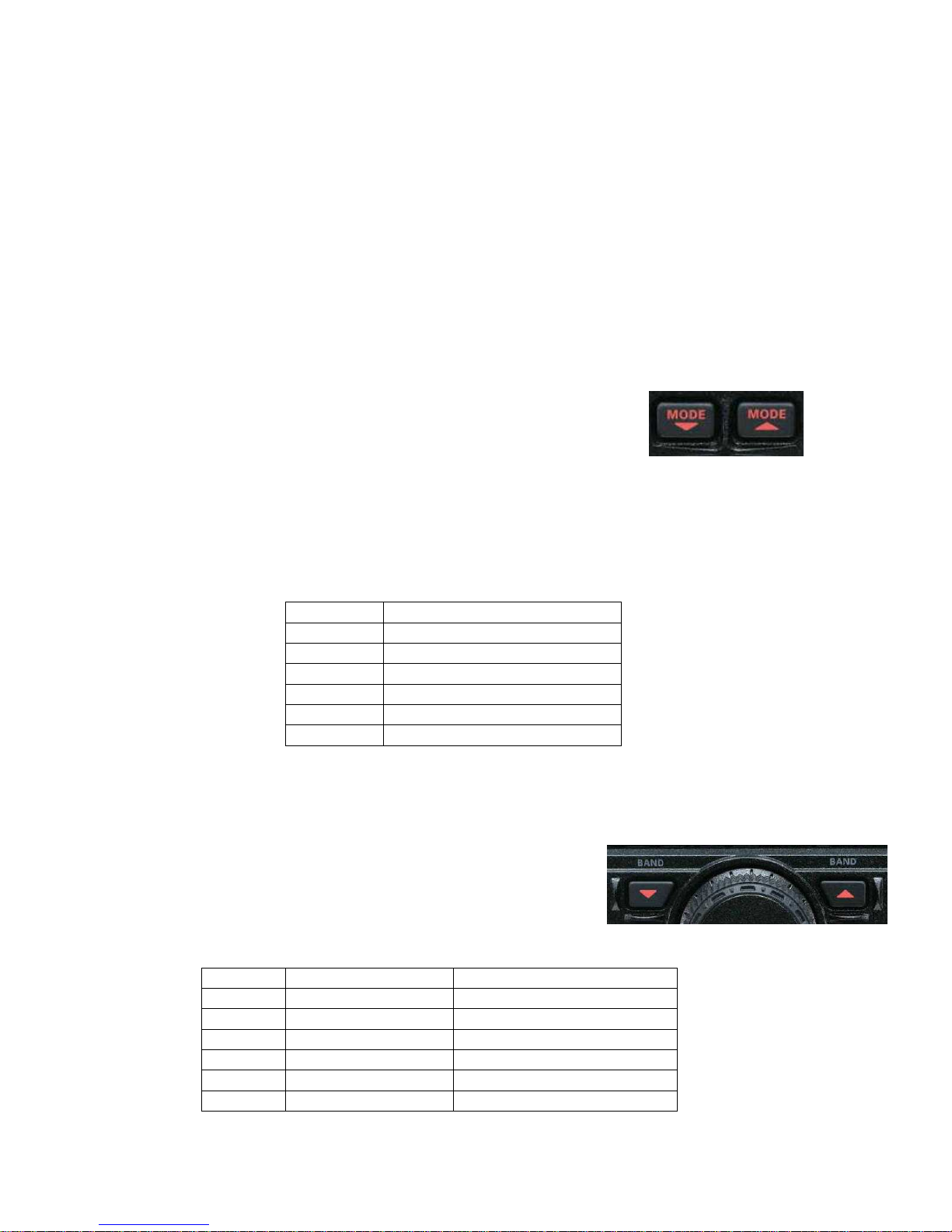
3.1 Communications Mode
The FT-450 transceiver is designed to communicate using Lower Side Band
(LSB), Upper Side Band (USB), Continuous Wave (CW, i.e. Morse code),
Data (DATA), Amplitude Modulation (AM), or Frequency Modulation (FM).
Pressing either the “MODE▼” or “MODE▲” will step through the available
modes in the forward or reverse direction respectively. These buttons are found to the right of the
“DSP/SEL” knob. Any unwanted modes may be turned off in adaptation using the MENU functions
described later.
Most user’s will not need all of the communication modes shown in Table 2. When you get to the section
on adaptation, you will find that you can configure the system to skip any modes that are not needed.
MODE DESCRIPTION
USB Upper side band
LSB Lower side band
CW Continuous Wave
AM Amplitude Modulation
FM Frequency Modulation
DATA Radio teletype, Packet
Table 2 – Communication Modes
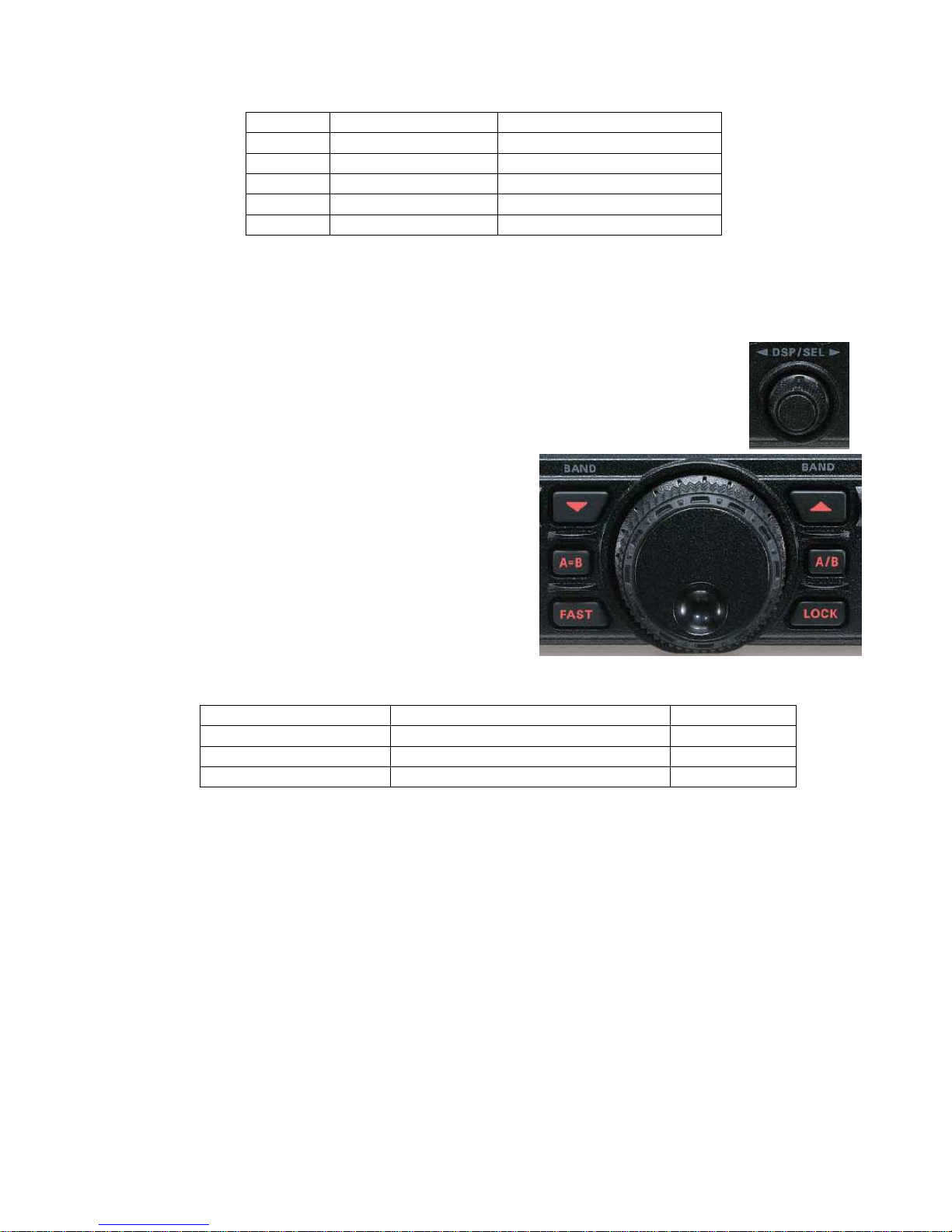
3.2 Band
Step through the bands using ”BAND▲” and “BAND▼” buttons on either
side of the “MAIN” dial. Only those bands enabled (via the menu
command) will be selected. The available bands are shown in Table 1
above. Any unwanted bands may be turned off in adaptation using the
MENU functions described later.
BAND RANGE AMATEUR RADIO BAND
GEN 30 KHz ~ 33 MHz none (stores non-ham fqys )
1.8 MHz 30 KHz ~ 33 MHz 1.8 MHz ~ 2.0 MHz
3.5 MHz 30 KHz ~ 33 MHz 3.5 MHz ~ 4.0 MHz
7.0 MHz 30 KHz ~ 33 MHz 7.0 MHz ~ 7.3 MHz
10 MHz 30 KHz ~ 33 MHz 10.1 MHz ~ 10.15 MHz
14 MHz 30 KHz ~ 33 MHz 14 MHz ~ 14.35 MHz
- 4 -
YAESU HF/50 mHz Transceiver FT-450 User’s Manual
BAND RANGE AMATEUR RADIO BAND
18 MHz 30 KHz ~ 33 MHz 18.068 MHz ~ 18.168 MHz
21 MHz 30 KHz ~ 33 MHz 21 MHz ~21.45 MHz
24 MHz 30 KHz ~ 33 MHz 24.89 MHz ~ 24.99 MHz
28 MHz 30 KHz ~ 33 MHz 28 MHz ~ 29.7 MHz
50 MHz 33 MHz ~ 56 MHz 50 MHz ~ 54 MHz
Table 3 – Transceiver Bands
3.3 VFO (Variable Frequency Oscillator)
The display shows the current frequency in 10 Hz increments (left field is MHz, mid
field is KHz). The desired frequency is selected by rotating the “DSP/SEL” knob (24
steps per revolution). Tabke 5 shows the incremental step size. Factory defaults are
highlighted.
Press the “DSP/SEL” knob to blink the left 3 digits of
the frequency display and the “DSP/SEL” knob now
moves in 100 kHz increments changing only those
digits. Pressing the “DSP/SEL” knob again (or pressing
any button or moving the “MAIN” dial) stops the
blinking and the “DSP/SEL” knob action returns to the
smaller increment size.
The “MAIN” (large unlabeled) dial (100 steps per
revolution) allows fine-tuning of the frequency. The
“MAIN” dial is, by default, disabled in AM or FM
modes, but may be enabled by adaptation.
MODE(S) “DSP/SEL” KNOB “MAIN” DIAL
CW, LSB, USB, DATA 1.0, 2.5, 5.0 kHz 1, 10, 20 Hz
AM 2.5, 5.0, 9.0, 10, 12.5, 25 kHz 100, 200 Hz *
FM 5.0, 6.25,10, 12,.5, 15, 20, 25, 50 kHz 100, 200 Hz *
Table 5 – Base frequency step size for controls
*Note: By default, “MAIN” dial is inoperative for AM and FM modes unless enabled by adaptation.
To change the frequency step size of the “DSP/SEL” knob, f-press the “STEP/SPLIT” (just above “F■”).
The current step size will show on the bottom right of the display. Change the step size value by rotating
the “DSP/SEL” knob. When the correct value is displayed, press the “STEP/SPLIT” button to exit that
state.
Press the “FAST” button (to the left bottom of “MAIN” dial) to increase the speed of frequency selection.
The word FAST will be highlighted on the display, the “DSP/SEL” increments will be doubled and the
“MAIN” dial increments will be increased by a factor of 10. Pressing “FAST” again to extinguish the
FAST highlight and returns both knobs to their set increments.
The current frequency may be locked to avoid inadvertently changing it. To toggle the lock function,
press the “LOCK” button to the right of the “MAIN” dial. When locked, the word LOCK will appear
- 5 -
YAESU HF/50 mHz Transceiver FT-450 User’s Manual
above the right end of the frequency display. The frequency lock may be released by pressing “LOCK”
again.
In addition to the display, the FT-450 is able to announce the current frequency through
the speaker or headset. To hear the frequency, f-press the “VOICE” button (2nd upper
button from the right).
Note: Small changes in the receive frequency (under 10 kHz) my also be achieved by use
of the clarifier. See section 4.1.1 of transmission for details.
3.3.1 Clarifier
The receive frequency can be set up to +/-9.99 kHz different
from the transmit frequency. This is toggled on and off by
pressing the “CLAR” button located near the bottom middle
of the front panel. When activated, the word CLAR shows
on the right side of the display with the offset shown below
it (replacing the M-TUNE, VFO-A, or VFO-B on the
display). The offset value may be changed with the “MAIN”
dial. Note that the offset control may be re-assigned to the
“DSP/SEL” knob in adaptation using the MENU functions as described later.
The system will remember the offset value, even when CLAR is turned off. To zero the offset, t-press the
“CLAR” button while the clarifier is turned on. The offset will also be set to zero if the “MAIN” dial is
inadvertently turned when the CLAR is turned off.
3.3.2 Split Frequency Operation
The FT-450 Transceiver is capable of operating on two frequencies; one
for transmission and another for reception. Moreover, there is no restriction
that the two VFOs operate on the same band or even in the same mode.
To toggle split frequency operation, press the “STEP/SPLIT” button. The
work SPLIT is highlighted in the display. The current receive VFO setup
appears on the display. If you want to keep it, press either the “A = B” or “A
/ B” button to either put that setup in the transmit VFO or swap setups with
the current transmit VFO. Then enter the transmit frequency and any other parameters
associated with it and press the “A / B“ button to swap it with the receive VFO setup.
You are now ready to communicate. Whenever the Transceiver is transmitting, the frequency
display will show the transmit frequency. Otherwise it will show the receive frequency.
There is also a quick split feature in the system. If you t-press the “STEP/SPLIT” button, the
system will automatically copy the receive VFO into the transmit VFO and add 5 kHz to the
transmit frequency. You may now communicate as before.
Note: see section 5 for a better understanding of the contents of a VFO setup and section 5.5 a
more complete description of the “A = B” or “A / B” button action.
- 6 -
 Loading...