

Page 1

-- DISCONTINUED PRODUCT --
LogiCORE™ IP
1-Gigabit Ethernet
MAC v8.5
User Guide
UG144 April 24, 2009
R
Page 2

-- DISCONTINUED PRODUCT --
R
Xilinx is providing this product documentation, hereinafter “Information,” to you “AS IS” with no warranty of any kind, express or implied.
Xilinx makes no representation that the Information, or any particular implementation thereof, is free from any claims of infringement. You
are responsible for obtaining any rights you may require for any implementation based on the Information. All specifications are subject to
change without notice. XILINX EXPRESSLY DISCLAIMS ANY WARRANTY WHATSOEVER WITH RESPECT TO THE ADEQUACY OF
THE INFORMATION OR ANY IMPLEMENTATION BASED THEREON, INCLUDING BUT NOT LIMITED TO ANY WARRANTIES OR
REPRESENTATIONS THAT THIS IMPLEMENTATION IS FREE FROM CLAIMS OF INFRINGEMENT AND ANY IMPLIED WARRANTIES
OF MERCHANTABILITY OR FITNESS FOR A PARTICULAR PURPOSE. Except as stated herein, none of the Information may be copied,
reproduced, distributed, republished, downloaded, displayed, posted, or transmitted in any form or by any means including, but not limited
to, electronic, mechanical, photocopying, recording, or otherwise, without the prior written consent of Xilinx.
© 2004-2009 Xilinx, Inc. XILINX, the Xilinx logo, Virtex, Spartan, ISE and other designated brands included herein are trademarks of Xilinx
in the United States and other countries. The PowerPC name and logo are registered trademarks of IBM Corp. and used under license. All
other trademarks are the property of their respective owners.
www.xilinx.com 1-Gigabit Ethernet MAC v8.5 User Guide
UG144 April 24, 2009
Page 3

-- DISCONTINUED PRODUCT --
Revision History
The following table shows the revision history for this document.
Date Version Revision
09/30/04 1.0 Initial Xilinx release.
04/28/05 2.0 Updated to 1-Gigabit Ethernet MAC version 6.0, Xilinx tools v7.1i SP1.
01/18/06 3.0 Updated to 1-Gigabit Ethernet MAC version 7.0, Xilinx tools v8.1i.
07/13/06 4.0 Updated to 1-Gigabit Ethernet MAC version 8.0, Xilinx tools v8.2i.
09/21/06 4.1 Updated to 1-Gigabit Ethernet MAC version 8.1, added support for Spartan®-3A platform.
02/15/07 4.2 Updated to 1-Gigabit Ethernet MAC version 8.2, Xilinx tools v9.1i.
08/08/07 5.0 Advanced core version to 8.3, updated various tool versions and trademarks for the
IP1 I Jade Minor release.
03/24/08 6.0 Updated core version to 8.4; Xilinx tools 10.1.
04/24/09 7.0 Updated core version to 8.5; Xilinx tools 11.1.
The product was discontinued as of August 31, 2009.
1-Gigabit Ethernet MAC v8.5 User Guide www.xilinx.com
UG144 April 24, 2009
Page 4

-- DISCONTINUED PRODUCT --
www.xilinx.com 1-Gigabit Ethernet MAC v8.5 User Guide
UG144 April 24, 2009
Page 5

-- DISCONTINUED PRODUCT --
Table of Contents
Schedule of Figures. . . . . . . . . . . . . . . . . . . . . . . . . . . . . . . . . . . . . . . . . . . . . . . . . . . . . . . . . . 9
Schedule of Tables . . . . . . . . . . . . . . . . . . . . . . . . . . . . . . . . . . . . . . . . . . . . . . . . . . . . . . . . . . 13
Preface: About This Guide
Guide Contents . . . . . . . . . . . . . . . . . . . . . . . . . . . . . . . . . . . . . . . . . . . . . . . . . . . . . . . . . . . . . 15
Conventions . . . . . . . . . . . . . . . . . . . . . . . . . . . . . . . . . . . . . . . . . . . . . . . . . . . . . . . . . . . . . . . . 16
Typographical. . . . . . . . . . . . . . . . . . . . . . . . . . . . . . . . . . . . . . . . . . . . . . . . . . . . . . . . . . . . 16
Online Document . . . . . . . . . . . . . . . . . . . . . . . . . . . . . . . . . . . . . . . . . . . . . . . . . . . . . . . . . 17
List of Acronyms . . . . . . . . . . . . . . . . . . . . . . . . . . . . . . . . . . . . . . . . . . . . . . . . . . . . . . . . . 17
Chapter 1: Introduction
About the Core. . . . . . . . . . . . . . . . . . . . . . . . . . . . . . . . . . . . . . . . . . . . . . . . . . . . . . . . . . . . . . 19
Recommended Design Experience. . . . . . . . . . . . . . . . . . . . . . . . . . . . . . . . . . . . . . . . . . . 19
Additional Core Resources . . . . . . . . . . . . . . . . . . . . . . . . . . . . . . . . . . . . . . . . . . . . . . . . . . 19
Related Xilinx Ethernet Products and Services . . . . . . . . . . . . . . . . . . . . . . . . . . . . . . . 19
Specifications . . . . . . . . . . . . . . . . . . . . . . . . . . . . . . . . . . . . . . . . . . . . . . . . . . . . . . . . . . . . . . . 20
Technical Support. . . . . . . . . . . . . . . . . . . . . . . . . . . . . . . . . . . . . . . . . . . . . . . . . . . . . . . . . . . 20
Feedback. . . . . . . . . . . . . . . . . . . . . . . . . . . . . . . . . . . . . . . . . . . . . . . . . . . . . . . . . . . . . . . . . . . . 20
GEMAC Core . . . . . . . . . . . . . . . . . . . . . . . . . . . . . . . . . . . . . . . . . . . . . . . . . . . . . . . . . . . . 20
Document . . . . . . . . . . . . . . . . . . . . . . . . . . . . . . . . . . . . . . . . . . . . . . . . . . . . . . . . . . . . . . . 20
Chapter 2: Core Architecture
System Overview . . . . . . . . . . . . . . . . . . . . . . . . . . . . . . . . . . . . . . . . . . . . . . . . . . . . . . . . . . . 21
Core Components . . . . . . . . . . . . . . . . . . . . . . . . . . . . . . . . . . . . . . . . . . . . . . . . . . . . . . . . 22
Core Interfaces . . . . . . . . . . . . . . . . . . . . . . . . . . . . . . . . . . . . . . . . . . . . . . . . . . . . . . . . . . . . . . 23
GMAC Core with Optional Management Interface . . . . . . . . . . . . . . . . . . . . . . . . . . . . 23
GMAC Core Without Management Interface and With Address Filter . . . . . . . . . . . 24
GEMAC Core Without Management Interface and Without Address Filter . . . . . . . 25
Client Side Interface. . . . . . . . . . . . . . . . . . . . . . . . . . . . . . . . . . . . . . . . . . . . . . . . . . . . . . . 26
Physical Side Interface. . . . . . . . . . . . . . . . . . . . . . . . . . . . . . . . . . . . . . . . . . . . . . . . . . . . . 29
Chapter 3: Generating the Core
Graphical User Interface . . . . . . . . . . . . . . . . . . . . . . . . . . . . . . . . . . . . . . . . . . . . . . . . . . . . 31
Component Name . . . . . . . . . . . . . . . . . . . . . . . . . . . . . . . . . . . . . . . . . . . . . . . . . . . . . . . . 32
Management Interface. . . . . . . . . . . . . . . . . . . . . . . . . . . . . . . . . . . . . . . . . . . . . . . . . . . . . 32
Address Filter . . . . . . . . . . . . . . . . . . . . . . . . . . . . . . . . . . . . . . . . . . . . . . . . . . . . . . . . . . . . 32
Number of Address Table Entries . . . . . . . . . . . . . . . . . . . . . . . . . . . . . . . . . . . . . . . . . . . 32
Physical Interface . . . . . . . . . . . . . . . . . . . . . . . . . . . . . . . . . . . . . . . . . . . . . . . . . . . . . . . . . 32
Parameter Values in the XCO File . . . . . . . . . . . . . . . . . . . . . . . . . . . . . . . . . . . . . . . . . . . 32
Output Generation . . . . . . . . . . . . . . . . . . . . . . . . . . . . . . . . . . . . . . . . . . . . . . . . . . . . . . . . . . 33
1-Gigabit Ethernet MAC v8.5 User Guide www.xilinx.com
UG144 April 24, 2009
Page 6

-- DISCONTINUED PRODUCT --
R
Chapter 4: Designing with the Core
General Design Guidelines . . . . . . . . . . . . . . . . . . . . . . . . . . . . . . . . . . . . . . . . . . . . . . . . . 35
Design Steps . . . . . . . . . . . . . . . . . . . . . . . . . . . . . . . . . . . . . . . . . . . . . . . . . . . . . . . . . . . . . 35
Know the Degree of Difficulty . . . . . . . . . . . . . . . . . . . . . . . . . . . . . . . . . . . . . . . . . . . . . . 37
Keep it Registered . . . . . . . . . . . . . . . . . . . . . . . . . . . . . . . . . . . . . . . . . . . . . . . . . . . . . . . . 38
Recognize Timing Critical Signals . . . . . . . . . . . . . . . . . . . . . . . . . . . . . . . . . . . . . . . . . . . 38
Use Supported Design Flows . . . . . . . . . . . . . . . . . . . . . . . . . . . . . . . . . . . . . . . . . . . . . . . 38
Make Only Allowed Modifications . . . . . . . . . . . . . . . . . . . . . . . . . . . . . . . . . . . . . . . . . . 38
Chapter 5: Using the Client Side Data Path
Receiving Inbound Frames . . . . . . . . . . . . . . . . . . . . . . . . . . . . . . . . . . . . . . . . . . . . . . . . . . 39
Normal Frame Reception . . . . . . . . . . . . . . . . . . . . . . . . . . . . . . . . . . . . . . . . . . . . . . . . . . 39
rx_good_frame, rx_bad_frame timing . . . . . . . . . . . . . . . . . . . . . . . . . . . . . . . . . . . . . . . 40
Frame Reception with Errors . . . . . . . . . . . . . . . . . . . . . . . . . . . . . . . . . . . . . . . . . . . . . . . 41
Client-Supplied FCS Passing . . . . . . . . . . . . . . . . . . . . . . . . . . . . . . . . . . . . . . . . . . . . . . . 42
VLAN Tagged Frames. . . . . . . . . . . . . . . . . . . . . . . . . . . . . . . . . . . . . . . . . . . . . . . . . . . . . 42
Maximum Permitted Frame Length . . . . . . . . . . . . . . . . . . . . . . . . . . . . . . . . . . . . . . . . . 43
Length/Type Field Error Checks. . . . . . . . . . . . . . . . . . . . . . . . . . . . . . . . . . . . . . . . . . . . 43
Address Filter . . . . . . . . . . . . . . . . . . . . . . . . . . . . . . . . . . . . . . . . . . . . . . . . . . . . . . . . . . . . 44
Receiver Statistics Vector . . . . . . . . . . . . . . . . . . . . . . . . . . . . . . . . . . . . . . . . . . . . . . . . . . 44
Transmitting Outbound Frames . . . . . . . . . . . . . . . . . . . . . . . . . . . . . . . . . . . . . . . . . . . . . 47
Normal Frame Transmission . . . . . . . . . . . . . . . . . . . . . . . . . . . . . . . . . . . . . . . . . . . . . . . 47
Padding . . . . . . . . . . . . . . . . . . . . . . . . . . . . . . . . . . . . . . . . . . . . . . . . . . . . . . . . . . . . . . . . . 47
Client-Supplied FCS Passing . . . . . . . . . . . . . . . . . . . . . . . . . . . . . . . . . . . . . . . . . . . . . . . 48
Client Underrun . . . . . . . . . . . . . . . . . . . . . . . . . . . . . . . . . . . . . . . . . . . . . . . . . . . . . . . . . . 48
VLAN Tagged Frames. . . . . . . . . . . . . . . . . . . . . . . . . . . . . . . . . . . . . . . . . . . . . . . . . . . . . 49
Maximum Permitted Frame Length . . . . . . . . . . . . . . . . . . . . . . . . . . . . . . . . . . . . . . . . . 49
Inter-Frame Gap Adjustment . . . . . . . . . . . . . . . . . . . . . . . . . . . . . . . . . . . . . . . . . . . . . . . 49
Transmitter Statistics Vector. . . . . . . . . . . . . . . . . . . . . . . . . . . . . . . . . . . . . . . . . . . . . . . . 50
Chapter 6: Using Flow Control
Overview of Flow Control. . . . . . . . . . . . . . . . . . . . . . . . . . . . . . . . . . . . . . . . . . . . . . . . . . . 53
Flow Control Requirement . . . . . . . . . . . . . . . . . . . . . . . . . . . . . . . . . . . . . . . . . . . . . . . . . 53
Flow Control Basics . . . . . . . . . . . . . . . . . . . . . . . . . . . . . . . . . . . . . . . . . . . . . . . . . . . . . . . 54
Pause Control Frames . . . . . . . . . . . . . . . . . . . . . . . . . . . . . . . . . . . . . . . . . . . . . . . . . . . . . 55
Flow Control Operation of the GEMAC . . . . . . . . . . . . . . . . . . . . . . . . . . . . . . . . . . . . . 56
Transmitting a PAUSE Control Frame . . . . . . . . . . . . . . . . . . . . . . . . . . . . . . . . . . . . . . . 56
Receiving a Pause Control Frame . . . . . . . . . . . . . . . . . . . . . . . . . . . . . . . . . . . . . . . . . . . 57
Flow Control Implementation Example . . . . . . . . . . . . . . . . . . . . . . . . . . . . . . . . . . . . . . 58
Chapter 7: Using the Physical Side Interface
Implementing External GMII. . . . . . . . . . . . . . . . . . . . . . . . . . . . . . . . . . . . . . . . . . . . . . . . 61
GMII Transmitter Logic . . . . . . . . . . . . . . . . . . . . . . . . . . . . . . . . . . . . . . . . . . . . . . . . . . . 61
GMII Receiver Logic . . . . . . . . . . . . . . . . . . . . . . . . . . . . . . . . . . . . . . . . . . . . . . . . . . . . . . 63
Implementing External RGMII . . . . . . . . . . . . . . . . . . . . . . . . . . . . . . . . . . . . . . . . . . . . . . 66
RGMII Transmitter Logic . . . . . . . . . . . . . . . . . . . . . . . . . . . . . . . . . . . . . . . . . . . . . . . . . . 66
RGMII Receiver Logic . . . . . . . . . . . . . . . . . . . . . . . . . . . . . . . . . . . . . . . . . . . . . . . . . . . . . 70
RGMII Inband Status Decoding Logic . . . . . . . . . . . . . . . . . . . . . . . . . . . . . . . . . . . . . . . 75
Using the MDIO interface. . . . . . . . . . . . . . . . . . . . . . . . . . . . . . . . . . . . . . . . . . . . . . . . . . . 76
www.xilinx.com 1-Gigabit Ethernet MAC v8.5 User Guide
UG144 April 24, 2009
Page 7

-- DISCONTINUED PRODUCT --
Connecting the MDIO to an Internally Integrated PHY . . . . . . . . . . . . . . . . . . . . . . . . 76
Connecting the MDIO to an External PHY . . . . . . . . . . . . . . . . . . . . . . . . . . . . . . . . . . . 76
Chapter 8: Configuration and Status
Using the Optional Management Interface. . . . . . . . . . . . . . . . . . . . . . . . . . . . . . . . . . . 77
Host Clock Frequency . . . . . . . . . . . . . . . . . . . . . . . . . . . . . . . . . . . . . . . . . . . . . . . . . . . . . 77
Configuration Registers . . . . . . . . . . . . . . . . . . . . . . . . . . . . . . . . . . . . . . . . . . . . . . . . . . . 78
MDIO Interface. . . . . . . . . . . . . . . . . . . . . . . . . . . . . . . . . . . . . . . . . . . . . . . . . . . . . . . . . . . 86
Access without the Management Interface . . . . . . . . . . . . . . . . . . . . . . . . . . . . . . . . . . . 90
Chapter 9: Constraining the Core
Required Constraints. . . . . . . . . . . . . . . . . . . . . . . . . . . . . . . . . . . . . . . . . . . . . . . . . . . . . . . . 93
Device, Package, and Speedgrade Selection . . . . . . . . . . . . . . . . . . . . . . . . . . . . . . . . . . 93
I/O Location Constraints . . . . . . . . . . . . . . . . . . . . . . . . . . . . . . . . . . . . . . . . . . . . . . . . . . 93
Placement Constraints . . . . . . . . . . . . . . . . . . . . . . . . . . . . . . . . . . . . . . . . . . . . . . . . . . . . . 93
Timing Constraints . . . . . . . . . . . . . . . . . . . . . . . . . . . . . . . . . . . . . . . . . . . . . . . . . . . . . . . 93
Constraints when Implementing an External GMII . . . . . . . . . . . . . . . . . . . . . . . . . . . . 96
Understanding Timing Reports for GMII Setup/Hold Timing . . . . . . . . . . . . . . . . . . 99
Constraints when Implementing an External RGMII . . . . . . . . . . . . . . . . . . . . . . . . . . 101
Understanding Timing Reports for RGMII Setup/Hold timing . . . . . . . . . . . . . . . . 105
R
Chapter 10: Clocking and Resetting
Clocking the Core . . . . . . . . . . . . . . . . . . . . . . . . . . . . . . . . . . . . . . . . . . . . . . . . . . . . . . . . . . 109
With Internal GMII . . . . . . . . . . . . . . . . . . . . . . . . . . . . . . . . . . . . . . . . . . . . . . . . . . . . . . 109
With External GMII . . . . . . . . . . . . . . . . . . . . . . . . . . . . . . . . . . . . . . . . . . . . . . . . . . . . . . 109
With RGMII. . . . . . . . . . . . . . . . . . . . . . . . . . . . . . . . . . . . . . . . . . . . . . . . . . . . . . . . . . . . . 110
Multiple Cores . . . . . . . . . . . . . . . . . . . . . . . . . . . . . . . . . . . . . . . . . . . . . . . . . . . . . . . . . . . . . 110
With External GMII . . . . . . . . . . . . . . . . . . . . . . . . . . . . . . . . . . . . . . . . . . . . . . . . . . . . . . 110
With RGMII. . . . . . . . . . . . . . . . . . . . . . . . . . . . . . . . . . . . . . . . . . . . . . . . . . . . . . . . . . . . . 111
Reset Conditions . . . . . . . . . . . . . . . . . . . . . . . . . . . . . . . . . . . . . . . . . . . . . . . . . . . . . . . . . . . 112
Chapter 11: Interfacing to Other Cores
Ethernet 1000Base-X PCS/PMA or SGMII Core . . . . . . . . . . . . . . . . . . . . . . . . . . . . . 113
Integration to Provide 1000BASE-X PCS with TBI . . . . . . . . . . . . . . . . . . . . . . . . . . . . 114
Integration to Provide 1000BASE-X PCS and PMA using a RocketIO Transceiver . 115
Integration to Provide SGMII Functionality . . . . . . . . . . . . . . . . . . . . . . . . . . . . . . . . . 119
Ethernet Statistics Core. . . . . . . . . . . . . . . . . . . . . . . . . . . . . . . . . . . . . . . . . . . . . . . . . . . . . 119
Connecting the Ethernet Statistics Core to Provide Statistics Gathering. . . . . . . . . . 119
1-Gigabit Ethernet MAC v8.5 User Guide www.xilinx.com
UG144 April 24, 2009
Page 8

-- DISCONTINUED PRODUCT --
R
Chapter 12: Implementing Your Design
Pre-implementation Simulation . . . . . . . . . . . . . . . . . . . . . . . . . . . . . . . . . . . . . . . . . . . . 123
Using the Simulation Model. . . . . . . . . . . . . . . . . . . . . . . . . . . . . . . . . . . . . . . . . . . . . . . 123
Synthesis . . . . . . . . . . . . . . . . . . . . . . . . . . . . . . . . . . . . . . . . . . . . . . . . . . . . . . . . . . . . . . . . . . 123
XST—VHDL . . . . . . . . . . . . . . . . . . . . . . . . . . . . . . . . . . . . . . . . . . . . . . . . . . . . . . . . . . . . 123
XST—Verilog . . . . . . . . . . . . . . . . . . . . . . . . . . . . . . . . . . . . . . . . . . . . . . . . . . . . . . . . . . . 124
Implementation . . . . . . . . . . . . . . . . . . . . . . . . . . . . . . . . . . . . . . . . . . . . . . . . . . . . . . . . . . . . 124
Generating the Xilinx Netlist . . . . . . . . . . . . . . . . . . . . . . . . . . . . . . . . . . . . . . . . . . . . . . 124
Mapping the Design . . . . . . . . . . . . . . . . . . . . . . . . . . . . . . . . . . . . . . . . . . . . . . . . . . . . . 124
Placing-and-Routing the Design . . . . . . . . . . . . . . . . . . . . . . . . . . . . . . . . . . . . . . . . . . . 125
Static Timing Analysis. . . . . . . . . . . . . . . . . . . . . . . . . . . . . . . . . . . . . . . . . . . . . . . . . . . . 125
Generating a Bitstream . . . . . . . . . . . . . . . . . . . . . . . . . . . . . . . . . . . . . . . . . . . . . . . . . . . 125
Post-Implementation Simulation . . . . . . . . . . . . . . . . . . . . . . . . . . . . . . . . . . . . . . . . . . . 125
Generating a Simulation Model . . . . . . . . . . . . . . . . . . . . . . . . . . . . . . . . . . . . . . . . . . . . 125
Using the Model . . . . . . . . . . . . . . . . . . . . . . . . . . . . . . . . . . . . . . . . . . . . . . . . . . . . . . . . . 126
Other Implementation Information. . . . . . . . . . . . . . . . . . . . . . . . . . . . . . . . . . . . . . . . . 126
Appendix A: Using the Client-Side FIFO
Interfaces . . . . . . . . . . . . . . . . . . . . . . . . . . . . . . . . . . . . . . . . . . . . . . . . . . . . . . . . . . . . . . . . . . 128
Transmit FIFO. . . . . . . . . . . . . . . . . . . . . . . . . . . . . . . . . . . . . . . . . . . . . . . . . . . . . . . . . . . 128
Receive FIFO . . . . . . . . . . . . . . . . . . . . . . . . . . . . . . . . . . . . . . . . . . . . . . . . . . . . . . . . . . . . 129
Overview of LocalLink Interface . . . . . . . . . . . . . . . . . . . . . . . . . . . . . . . . . . . . . . . . . . . 130
Data Flow . . . . . . . . . . . . . . . . . . . . . . . . . . . . . . . . . . . . . . . . . . . . . . . . . . . . . . . . . . . . . . 130
Functional Operation. . . . . . . . . . . . . . . . . . . . . . . . . . . . . . . . . . . . . . . . . . . . . . . . . . . . . . . 131
Clock Requirements. . . . . . . . . . . . . . . . . . . . . . . . . . . . . . . . . . . . . . . . . . . . . . . . . . . . . . 131
Receive FIFO . . . . . . . . . . . . . . . . . . . . . . . . . . . . . . . . . . . . . . . . . . . . . . . . . . . . . . . . . . . . 131
Transmit FIFO. . . . . . . . . . . . . . . . . . . . . . . . . . . . . . . . . . . . . . . . . . . . . . . . . . . . . . . . . . . 131
Expanding Maximum Frame Size . . . . . . . . . . . . . . . . . . . . . . . . . . . . . . . . . . . . . . . . . . 132
User Interface Data Width Conversion. . . . . . . . . . . . . . . . . . . . . . . . . . . . . . . . . . . . . . 132
Appendix B: Core Verification, Compliance, and Interoperability
Verification by Simulation . . . . . . . . . . . . . . . . . . . . . . . . . . . . . . . . . . . . . . . . . . . . . . . . . 133
Hardware Verification . . . . . . . . . . . . . . . . . . . . . . . . . . . . . . . . . . . . . . . . . . . . . . . . . . . . . 133
Appendix C: Calculating DCM Phase-Shifting
DCM Phase-Shifting . . . . . . . . . . . . . . . . . . . . . . . . . . . . . . . . . . . . . . . . . . . . . . . . . . . . . . . 135
Finding the Ideal Phase-Shift. . . . . . . . . . . . . . . . . . . . . . . . . . . . . . . . . . . . . . . . . . . . . . . 135
Appendix D: Core Latency
Transmit Path Latency . . . . . . . . . . . . . . . . . . . . . . . . . . . . . . . . . . . . . . . . . . . . . . . . . . . . . 137
Receive Path Latency . . . . . . . . . . . . . . . . . . . . . . . . . . . . . . . . . . . . . . . . . . . . . . . . . . . . . . . 137
www.xilinx.com 1-Gigabit Ethernet MAC v8.5 User Guide
UG144 April 24, 2009
Page 9

-- DISCONTINUED PRODUCT --
Schedule of Figures
Chapter 1: Introduction
Chapter 2: Core Architecture
Figure 2-1: Block Diagram . . . . . . . . . . . . . . . . . . . . . . . . . . . . . . . . . . . . . . . . . . . . . . . . . . . . . 21
Figure 2-2: Component Pinout for MAC with Optional Management Interface . . . . . . 23
Figure 2-3: Component Pinout for MAC without Optional Management Interface
and with Optional Address Filter. . . . . . . . . . . . . . . . . . . . . . . . . . . . . . . . . . . . . . . . . . . . . 24
Figure 2-4: Component Pinout for MAC without Optional Management Interface or
Optional Address Filter . . . . . . . . . . . . . . . . . . . . . . . . . . . . . . . . . . . . . . . . . . . . . . . . . . . . . 25
Chapter 3: Generating the Core
Figure 3-1: 1-Gigabit Ethernet MAC Main Screen. . . . . . . . . . . . . . . . . . . . . . . . . . . . . . . . . 31
Chapter 4: Designing with the Core
Figure 4-1: 1-Gigabit Ethernet MAC Core Example Design . . . . . . . . . . . . . . . . . . . . . . . . 36
Chapter 5: Using the Client Side Data Path
Figure 5-1: Normal Frame Reception . . . . . . . . . . . . . . . . . . . . . . . . . . . . . . . . . . . . . . . . . . . . 40
Figure 5-2: Frame Reception with Error . . . . . . . . . . . . . . . . . . . . . . . . . . . . . . . . . . . . . . . . . . 41
Figure 5-3: Frame Reception with In-Band FCS Field. . . . . . . . . . . . . . . . . . . . . . . . . . . . . . 42
Figure 5-4: Reception of a VLAN Tagged Frame . . . . . . . . . . . . . . . . . . . . . . . . . . . . . . . . . . 42
Figure 5-5: Receiver Statistics Vector Timing. . . . . . . . . . . . . . . . . . . . . . . . . . . . . . . . . . . . . 44
Figure 5-6: Normal Frame Transmission . . . . . . . . . . . . . . . . . . . . . . . . . . . . . . . . . . . . . . . . . 47
Figure 5-7: Frame Transmission with Client-supplied FCS. . . . . . . . . . . . . . . . . . . . . . . . . 48
Figure 5-8: Frame Transmission with Underrun . . . . . . . . . . . . . . . . . . . . . . . . . . . . . . . . . . 48
Figure 5-9: Transmission of a VLAN Tagged Frame . . . . . . . . . . . . . . . . . . . . . . . . . . . . . . . 49
Figure 5-10: Inter-Frame Gap Adjustment. . . . . . . . . . . . . . . . . . . . . . . . . . . . . . . . . . . . . . . . 50
Figure 5-11: Transmitter Statistic Vector Timing . . . . . . . . . . . . . . . . . . . . . . . . . . . . . . . . . . 50
Chapter 6: Using Flow Control
Figure 6-1: Requirement for Flow Control . . . . . . . . . . . . . . . . . . . . . . . . . . . . . . . . . . . . . . . 53
Figure 6-2: MAC Control Frame Format . . . . . . . . . . . . . . . . . . . . . . . . . . . . . . . . . . . . . . . . . 55
Figure 6-3: Pause Request Timing. . . . . . . . . . . . . . . . . . . . . . . . . . . . . . . . . . . . . . . . . . . . . . . 56
Figure 6-4: Flow Control Implementation Triggered from FIFO Occupancy. . . . . . . . . . 59
1-Gigabit Ethernet MAC v8.5 User Guide www.xilinx.com 9
UG144 April 24, 2009
Page 10

-- DISCONTINUED PRODUCT --
R
Chapter 7: Using the Physical Side Interface
Figure 7-1: External GMII Transmitter Logic . . . . . . . . . . . . . . . . . . . . . . . . . . . . . . . . . . . . . 62
Figure 7-2: External GMII Receiver Logic for Spartan-3, Spartan-3E, and
Spartan-3A Devices . . . . . . . . . . . . . . . . . . . . . . . . . . . . . . . . . . . . . . . . . . . . . . . . . . . . . . . . . 63
Figure 7-3: External GMII Receiver Logic for Virtex-5 Devices . . . . . . . . . . . . . . . . . . . . . 65
Figure 7-4: External RGMII Transmitter Logic. . . . . . . . . . . . . . . . . . . . . . . . . . . . . . . . . . . . 66
Figure 7-5: External RGMII Transmitter Logic in Virtex-4 Devices. . . . . . . . . . . . . . . . . . 68
Figure 7-6: External RGMII Transmitter Logic in Virtex-5 Devices. . . . . . . . . . . . . . . . . . 69
Figure 7-7: External RGMII Receiver Logic . . . . . . . . . . . . . . . . . . . . . . . . . . . . . . . . . . . . . . 71
Figure 7-8: External RGMII Receiver Logic for Virtex-4 Devices. . . . . . . . . . . . . . . . . . . . 73
Figure 7-9: External RGMII Receiver Logic for Virtex-5 Devices. . . . . . . . . . . . . . . . . . . . 74
Figure 7-10: RGMII Inband Status Decoding Logic . . . . . . . . . . . . . . . . . . . . . . . . . . . . . . . 75
Figure 7-11: Creating an External MDIO Interface . . . . . . . . . . . . . . . . . . . . . . . . . . . . . . . . 76
Chapter 8: Configuration and Status
Figure 8-1: Configuration Register Write Timing . . . . . . . . . . . . . . . . . . . . . . . . . . . . . . . . . 84
Figure 8-2: Configuration Register Read Timing. . . . . . . . . . . . . . . . . . . . . . . . . . . . . . . . . . 84
Figure 8-3: Address Table Write Timing . . . . . . . . . . . . . . . . . . . . . . . . . . . . . . . . . . . . . . . . . 85
Figure 8-4: Address Table Read Timing . . . . . . . . . . . . . . . . . . . . . . . . . . . . . . . . . . . . . . . . . 86
Figure 8-5: Typical MDIO-managed System . . . . . . . . . . . . . . . . . . . . . . . . . . . . . . . . . . . . . 87
Figure 8-6: MDIO Write Transaction . . . . . . . . . . . . . . . . . . . . . . . . . . . . . . . . . . . . . . . . . . . . 87
Figure 8-7: MDIO Read Transaction. . . . . . . . . . . . . . . . . . . . . . . . . . . . . . . . . . . . . . . . . . . . . 88
Figure 8-8: MDIO Access through Management Interface . . . . . . . . . . . . . . . . . . . . . . . . . 89
Chapter 9: Constraining the Core
Figure 9-1: Input GMII Timing . . . . . . . . . . . . . . . . . . . . . . . . . . . . . . . . . . . . . . . . . . . . . . . . . 97
Figure 9-2: Timing Report Setup/Hold Illustration. . . . . . . . . . . . . . . . . . . . . . . . . . . . . . . 101
Figure 9-3: Input RGMII Timing. . . . . . . . . . . . . . . . . . . . . . . . . . . . . . . . . . . . . . . . . . . . . . . 102
Figure 9-4: Timing Report Setup/Hold Illustration. . . . . . . . . . . . . . . . . . . . . . . . . . . . . . . 107
Chapter 10: Clocking and Resetting
Figure 10-1: Clock Management Logic with External GMII . . . . . . . . . . . . . . . . . . . . . . . 109
Figure 10-2: Clock Management with External RGMII . . . . . . . . . . . . . . . . . . . . . . . . . . . 110
Figure 10-3: Clock Management Logic with External GMII (Multiple Cores). . . . . . . . 111
Figure 10-4: Clock Management Logic with External RGMII (Multiple Cores) . . . . . . 112
Figure 10-5: Reset Circuit for a Single Clock/reset Domain. . . . . . . . . . . . . . . . . . . . . . . . 112
10 www.xilinx.com 1-Gigabit Ethernet MAC v8.5 User Guide
UG144 April 24, 2009
Page 11

-- DISCONTINUED PRODUCT --
Chapter 11: Interfacing to Other Cores
Figure 11-1: 1-Gigabit Ethernet MAC Extended to Include 1000BASE-X PCS with TBI 114
Figure 11-2: 1-Gigabit Ethernet MAC Extended to Include 1000BASE-X PCS and PMA
using a RocketIO Transceiver . . . . . . . . . . . . . . . . . . . . . . . . . . . . . . . . . . . . . . . . . . . . . . . 115
Figure 11-3: 1-Gigabit Ethernet MAC Extended to Include 1000BASE-X PCS and PMA
using a RocketIO transceiver. . . . . . . . . . . . . . . . . . . . . . . . . . . . . . . . . . . . . . . . . . . . . . . . 117
Figure 11-4: 1-Gigabit Ethernet MAC Extended to Include 1000BASE-X PCS and PMA
using the RocketIO transceiver. . . . . . . . . . . . . . . . . . . . . . . . . . . . . . . . . . . . . . . . . . . . . . 118
Figure 11-5: Interfacing the Ethernet Statistics to the 1-Gigabit Ethernet MAC . . . . . . 120
Chapter 12: Implementing Your Design
Appendix A: Using the Client-Side FIFO
Figure A-1: Typical 10 Mbps/100 Mbps/ 1 Gbps Ethernet FIFO Implementation. . . . . 127
Figure A-2: Frame Transfer across LocalLink Interface . . . . . . . . . . . . . . . . . . . . . . . . . . . 130
Figure A-3: Frame Transfer with Flow Control . . . . . . . . . . . . . . . . . . . . . . . . . . . . . . . . . . 130
R
Appendix B: Core Verification, Compliance, and Interoperability
Appendix C: Calculating DCM Phase-Shifting
Appendix D: Core Latency
1-Gigabit Ethernet MAC v8.5 User Guide www.xilinx.com 11
UG144 April 24, 2009
Page 12

-- DISCONTINUED PRODUCT --
R
12 www.xilinx.com 1-Gigabit Ethernet MAC v8.5 User Guide
UG144 April 24, 2009
Page 13

-- DISCONTINUED PRODUCT --
Schedule of Tables
Chapter 1: Introduction
Chapter 2: Core Architecture
Table 2-1: Transmitter Client Interface Signal Pins. . . . . . . . . . . . . . . . . . . . . . . . . . . . . . . . 26
Table 2-2: Receive Client Interface Signal Pins . . . . . . . . . . . . . . . . . . . . . . . . . . . . . . . . . . . 27
Table 2-3: Flow Control Interface Signal Pinout . . . . . . . . . . . . . . . . . . . . . . . . . . . . . . . . . . 27
Table 2-4: Optional Management Interface Signal Pinout. . . . . . . . . . . . . . . . . . . . . . . . . . 28
Table 2-5: Optional MAC Unicast Address Signal Pinout . . . . . . . . . . . . . . . . . . . . . . . . . . 28
Table 2-6: Optional Configuration Vector Signal Pinout. . . . . . . . . . . . . . . . . . . . . . . . . . . 29
Table 2-7: Reset Signal. . . . . . . . . . . . . . . . . . . . . . . . . . . . . . . . . . . . . . . . . . . . . . . . . . . . . . . . . 29
Table 2-8: GMII Interface Signal Pinout . . . . . . . . . . . . . . . . . . . . . . . . . . . . . . . . . . . . . . . . . 29
Table 2-9: MDIO Interface Signal Pinout . . . . . . . . . . . . . . . . . . . . . . . . . . . . . . . . . . . . . . . . 30
Chapter 3: Generating the Core
Table 3-1: XCO File Values and Default Values. . . . . . . . . . . . . . . . . . . . . . . . . . . . . . . . . . . 33
Chapter 4: Designing with the Core
Table 4-1: Degree of Difficulty for Various Implementations . . . . . . . . . . . . . . . . . . . . . . 38
Chapter 5: Using the Client Side Data Path
Table 5-1: Abbreviations Used in Timing Diagrams. . . . . . . . . . . . . . . . . . . . . . . . . . . . . . . 39
Table 5-2: Bit Definition for the Receiver Statistics Vector . . . . . . . . . . . . . . . . . . . . . . . . . 45
Table 5-3: Rx Statistics conversion to previous core GEMAC core versions. . . . . . . . . . . 46
Table 5-4: Bit Definition for the Transmitter Statistics Vector . . . . . . . . . . . . . . . . . . . . . . 51
Table 5-5: Tx Statistics conversion to previous core GEMAC core versions. . . . . . . . . . . 52
Chapter 6: Using Flow Control
Chapter 7: Using the Physical Side Interface
Chapter 8: Configuration and Status
Table 8-1: Management Interface Transaction Types . . . . . . . . . . . . . . . . . . . . . . . . . . . . . . 77
Table 8-2: Configuration Registers . . . . . . . . . . . . . . . . . . . . . . . . . . . . . . . . . . . . . . . . . . . . . . 78
Table 8-3: Receiver Configuration Word 0. . . . . . . . . . . . . . . . . . . . . . . . . . . . . . . . . . . . . . . . 79
Table 8-4: Receiver Configuration Word 1. . . . . . . . . . . . . . . . . . . . . . . . . . . . . . . . . . . . . . . . 79
Table 8-5: Transmitter Configuration Word . . . . . . . . . . . . . . . . . . . . . . . . . . . . . . . . . . . . . . 80
Table 8-6: Flow Control Configuration Word . . . . . . . . . . . . . . . . . . . . . . . . . . . . . . . . . . . . . 81
Table 8-7: Management Configuration Word . . . . . . . . . . . . . . . . . . . . . . . . . . . . . . . . . . . . . 82
1-Gigabit Ethernet MAC v8.5 User Guide www.xilinx.com 13
UG144 April 24, 2009
Page 14

-- DISCONTINUED PRODUCT --
R
Table 8-8: Unicast Address Word 0 . . . . . . . . . . . . . . . . . . . . . . . . . . . . . . . . . . . . . . . . . . . . . . 82
Table 8-9: Unicast Address Word 1 . . . . . . . . . . . . . . . . . . . . . . . . . . . . . . . . . . . . . . . . . . . . . . 82
Table 8-10: Address Table Configuration Word 0 . . . . . . . . . . . . . . . . . . . . . . . . . . . . . . . . . 83
Table 8-11: Address Table Configuration Word 1 . . . . . . . . . . . . . . . . . . . . . . . . . . . . . . . . . 83
Table 8-12: Address Filter Mode . . . . . . . . . . . . . . . . . . . . . . . . . . . . . . . . . . . . . . . . . . . . . . . . 83
Table 8-13: Configuration Vector Bit Definition . . . . . . . . . . . . . . . . . . . . . . . . . . . . . . . . . . 90
Chapter 9: Constraining the Core
Table 9-1: Input GMII Timing . . . . . . . . . . . . . . . . . . . . . . . . . . . . . . . . . . . . . . . . . . . . . . . . . . 97
Table 9-2: Input RGMII Timing . . . . . . . . . . . . . . . . . . . . . . . . . . . . . . . . . . . . . . . . . . . . . . . 102
Chapter 10: Clocking and Resetting
Chapter 11: Interfacing to Other Cores
Table 11-1: Management Interface Transaction Types . . . . . . . . . . . . . . . . . . . . . . . . . . . . 121
Chapter 12: Implementing Your Design
Appendix A: Using the Client-Side FIFO
Table A-1: Transmit FIFO Client Interface . . . . . . . . . . . . . . . . . . . . . . . . . . . . . . . . . . . . . . 128
Table A-2: Transmit FIFO LocalLink Interface. . . . . . . . . . . . . . . . . . . . . . . . . . . . . . . . . . . 128
Table A-3: Receive FIFO Client Interface. . . . . . . . . . . . . . . . . . . . . . . . . . . . . . . . . . . . . . . . 129
Table A-4: Receive FIFO LocalLink Interface . . . . . . . . . . . . . . . . . . . . . . . . . . . . . . . . . . . . 129
Appendix B: Core Verification, Compliance, and Interoperability
Appendix C: Calculating DCM Phase-Shifting
Appendix D: Core Latency
14 www.xilinx.com 1-Gigabit Ethernet MAC v8.5 User Guide
UG144 April 24, 2009
Page 15

-- DISCONTINUED PRODUCT --
R
About This Guide
The LogiCORE™ IP 1-Gigabit Ethernet MAC User Guide provides information about
generating the core, customizing and simulating the core utilizing the provided example
design, and running the design files through implementation using the Xilinx tools.
Guide Contents
This guide contains the following chapters:
• Preface, “About this Guide” introduces the organization and purpose of the guide
and the conventions used in this document.
• Chapter 1, “Introduction” describes the core and related information, including
recommended design experience, additional resources, technical support, and
submitting feedback to Xilinx.
• Chapter 2, “Core Architecture” provides an overview of the core and discusses the
Physical/Client signal interfaces.
• Chapter 3, “Generating the Core” describes the graphical user interface options used
to generate the core.
• Chapter 4, “Designing with the Core” through Chapter 8, “Configuration and Status”
describe design parameters, including how to initialize the core, generate and
consume core packets, and how to operate the Management Interface.
• Chapter 9, “Constraining the Core” describes the constraints associated with the core.
• Chapter 10, “Clocking and Resetting” discusses special design considerations
associated with clock management logic, including the Gigabit Media Independent
Interface (GMII) and Reduced Gigabit Media Independent Interface (RGMII) options.
• Chapter 11, “Interfacing to Other Cores” describes how to interface the 1-Gigabit
Ethernet MAC core to the Ethernet 1000BASE-X PCS/PMA or SGMII core and the
Ethernet Statistics core.
• Chapter 12, “Implementing Your Design” provides instructions for how to set up
synthesis, simulation, and implementation environments and how to generate a
bitstream through the design flow.
• Appendix A, “Using the Client-Side FIFO” describes the FIFO provided in the
example design that accompanies the GEMAC core.
• Appendix B, “Core Verification, Compliance, and Interoperability” describes how the
core was verified and certified for compliance.
• Appendix C, “Calculating DCM Phase-Shifting” provides information about how to
calculate the system timing requirements when using DCMs with the core.
• Appendix D, “Core Latency” describes the latency of the core.
Preface
1-Gigabit Ethernet MAC v8.5 User Guide www.xilinx.com 15
UG144 April 24, 2009
Page 16

-- DISCONTINUED PRODUCT --
R
Conventions
Typographical
Preface: About This Guide
This document uses the following conventions. An example illustrates each convention.
The following typographical conventions are used in this document:
Convention Meaning or Use Example
Messages, prompts, and
Courier font
Courier bold
Italic font
program files that the system
displays
Literal commands you enter in
a syntactical statement
Variables in a syntax
statement for which you must
supply values
References to other manuals See the User Guide for details.
speed grade: - 100
ngdbuild design_name
See the Development System
Reference Guide for more
information.
Emphasis in text
Dark Shading
Square brackets [ ]
Braces { }
Vertical bar |
Vertical ellipsis
.
.
.
Horizontal ellipsis . . . Omitted repetitive material
Notations
Items that are not supported
or reserved
An optional entry or
parameter. However, in bus
specifications, such as
bus[7:0], they are required.
A list of items from which you
must choose one or more
Separates items in a list of
choices
Repetitive material that has
been omitted
The prefix ‘0x’ or the suffix ‘h’
indicate hexadecimal notation
An ‘_n’ means the signal is
active low
If a wire is drawn so that it
overlaps the pin of a symbol,
the two nets are not connected.
This feature is not supported
ngdbuild [option_name]
design_name
lowpwr ={on|off}
lowpwr ={on|off}
IOB #1: Name = QOUT’
IOB #2: Name = CLKIN’
.
.
.
allow block block_name
loc1 loc2 ... locn;
A read of address
0x00112975 returned
45524943h.
usr_teof_n is active low.
16 www.xilinx.com 1-Gigabit Ethernet MAC v8.5 User Guide
UG144 April 24, 2009
Page 17
Conventions
Online Document
-- DISCONTINUED PRODUCT --
R
The following linking conventions are used in this document:
Convention Meaning or Use Example
Blue text
Blue, underlined text
List of Acronyms
The following table describes acronyms used in this manual.
Acronym Spelled Out
CLB Configurable Logic Block
DCM Digital Clock Manager
DDR Double Data Rate
FCS Frame Check Sequence
FPGA Field Programmable Gate Array.
GBIC Gigabit Interface Converter
Gbps Gigabit per second
Cross-reference link to a
location in the current
document
Hyperlink to a website (URL)
See the section “Additional
Resources” for details.
See “Title Formats” in
Chapter 1 for details.
Go to w
latest speed files.
ww.xilinx.com for the
GEMAC Gigabit Ethernet Media Access Controller
GMII Gigabit Media Independent Interface
HDL Hardware Description Language
IO Input/Output
IOB Input/Output Block
IP Intellectual Property
ISE® Integrated Software Environment
LSW Least Significant Word
MAC Media Access Controller
MDIO Management Data Input/Output
MHz Mega Hertz
MMD MDIO Managed Device
ms milliseconds
MSW Most Significant Word
1-Gigabit Ethernet MAC v8.5 User Guide www.xilinx.com 17
UG144 April 24, 2009
Page 18

-- DISCONTINUED PRODUCT --
R
Preface: About This Guide
Acronym Spelled Out
NCD Native Circuit Description
NGC Native Generic Circuit
NGD Native Generic Database
ns nanoseconds
PCB Printed Circuit Board
PCS Physical Coding Sublayer
PHY physical-side interface
PMA Physical Medium Attachment
PMD Physical Medium Dependent
RGMII Reduced Gigabit Media Independent Interface
SGMII Serial Gigabit Media Independent Interface
VHDL VHSIC Hardware Description Language
(VHSIC an acronym for Very High-Speed
Integrated Circuits).
VCS Verilog Compiled Simulator
VLAN Virtual LAN (Local Area Network)
18 www.xilinx.com 1-Gigabit Ethernet MAC v8.5 User Guide
UG144 April 24, 2009
Page 19

R
Introduction
The 1-Gigabit Ethernet MAC (GEMAC) core is a fully verified solution that supports
Verilog-HDL and VHDL. In addition, the example design provided with the core is
provided in both Verilog and VHDL.
This chapter introduces the GEMAC core and provides other related information,
including recommended design experience, additional resources, technical support, and
ways to submit feedback to Xilinx.
-- DISCONTINUED PRODUCT --
Chapter 1
About the Core
The GEMAC core is a Xilinx CORE Generator™ IP core, included in the latest IP Update on
the Xilinx IP Center. For detailed information about the core, see the GEMAC product
page. For information about licensing options, see Chapter 2, “Licensing the Core,” in the
1-Gigabit Ethernet MAC Getting Started Guide.
Recommended Design Experience
Although the GEMAC core is a fully verified solution, the challenge associated with
implementing a complete design varies, depending on the configuration and functionality
of the application. For best results, previous experience building high performance,
pipelined FPGA designs using Xilinx implementation software and user constraint files
(UCFs) is recommended.
Contact your local Xilinx representative for a closer review and estimation for your specific
requirements.
Additional Core Resources
For detailed information and updates about the GEMAC core, see the following
documents, located on the GEMAC product page
• 1-Gigabit Ethernet MAC Data Sheet
• 1-Gigabit Ethernet MAC Getting Started Guide
.
After generating the core, the 1-Gigabit Ethernet MAC Release Notes are available from the
document directory.
Related Xilinx Ethernet Products and Services
See the Ethernet Products and Services page.
1-Gigabit Ethernet MAC v8.5 User Guide www.xilinx.com 19
UG144 April 24, 2009
Page 20

R
Specifications
• IEEE 802.3 2005
• Reduced Gigabit Media Independent Interface (RGMII) version 2.0
Technical Support
For technical support, see support.xilinx.com/. Questions are routed to a team of engineers
with expertise using the GEMAC core.
Xilinx will provide technical support for use of this product as described in the 1-Gigabit
Ethernet MAC User Guide and the 1-Gigabit Ethernet MAC Getting Started Guide. Xilinx
cannot guarantee timing, functionality, or support of this product for designs that do not
follow these guidelines.
Feedback
Xilinx welcomes comments and suggestions about the GEMAC core and the
documentation supplied with the core.
-- DISCONTINUED PRODUCT --
Chapter 1: Introduction
GEMAC Core
For comments or suggestions about the GEMAC core, please submit a WebCase from
s
upport.xilinx.com/. Be sure to include the following information:
• Product name
• Core version number
• Explanation of your comments
Document
For comments or suggestions about this document, please submit a WebCase from
s
upport.xilinx.com/. Be sure to include the following information:
• Document title
• Document number
• Page number(s) to which your comments refer
• Explanation of your comments
20 www.xilinx.com 1-Gigabit Ethernet MAC v8.5 User Guide
UG144 April 24, 2009
Page 21
-- DISCONTINUED PRODUCT --
R
Core Architecture
This chapter describes the GEMAC core architecture, including the major functional blocks
and all interfaces.
System Overview
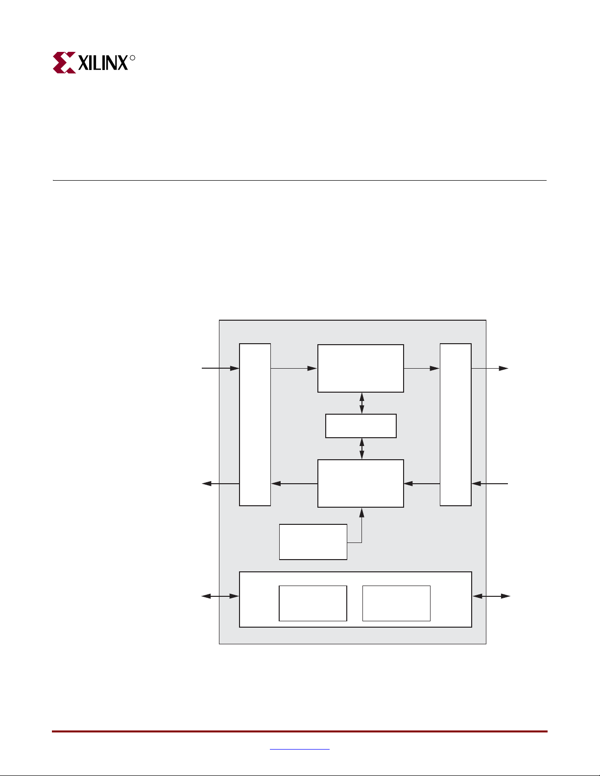
Figure 2-1 illustrates a block diagram of the GEMAC core with all the major functional
blocks and interfaces. Descriptions of the functional blocks and interfaces are provided in
the sections that follow.
Chapter 2
Client
Tr ansmitter
Interface
Client
Receiver
Interface
Client
Management
Interface
Gigabit Ethernet MAC Core
Client Interface
Optional
Address
Filter
Configuration MDIO
Tr ansmit Engine
Flow Control
Receive Engine
Optional Management
GMII Block
To Physical
Sublayers
Figure 2-1: Block Diagram
1-Gigabit Ethernet MAC v8.5 User Guide www.xilinx.com 21
UG144 April 24, 2009
Page 22

R
Core Components
Transmit Engine
The Transmit Engine accepts Ethernet frame data from the Client Transmitter Interface,
adds the preamble field to the start of the frame, adds padding bytes (if required) to ensure
that the frame meets the minimum frame length requirements, and adds the frame check
sequence (when configured to do so). The transmitter also ensures that the inter-frame
spacing between successive frames is at least the minimum specified. The frame is then
converted into a format that is compatible with the GMII and sent to the GMII Block.
Receive Engine
The Receive Engine accepts Ethernet frame data from the GMII Block, removes the
preamble field at the start of the frame, removes padding bytes and Frame Check Sequence
(if required, and when configured to do so). The receiver also performs error detection on
the received frame using information such as the frame check sequence field, received
GMII error codes, and legal frame size boundaries.
-- DISCONTINUED PRODUCT --
Chapter 2: Core Architecture
Flow Control
The Flow Control block is designed to clause 31 of the IEEE 802.3-2005 standard. The MAC
may be configured to send pause frames and to act upon their reception. These two
behaviors can be configured independently.
Address Filter
The Address Filter checks the address of incoming frames into the receiver. If the Address
Filter is enabled, the device will not pass frames that do not contain one of a set of known
addresses to the client.
Management Interface
The optional processor-independent Management Interface has standard address, data,
and control signals. It may be used as is, or you can apply a logical shim to interface to
common bus architectures. See Chapter 8, “Configuration and Status.”
This interface is used to access the following blocks.
• Configuration Register After power up or reset, the client may reconfigure the core
parameters from their defaults. Configuration changes can be written at any time.
• MDIO Interface The Management Interface is also used to access the MDIO interface
of the GEMAC core; this interface is typically connected to the MDIO port of a
physical layer device (PHY) to access its configuration and status registers. The MDIO
format is defined in IEEE802.3 clause 22.
GMII Block
This implements GMII style signaling for the physical interface of the core and is typically
attached to a physical layer device (PHY), either off-chip or internally integrated.
22 www.xilinx.com 1-Gigabit Ethernet MAC v8.5 User Guide
UG144 April 24, 2009
Page 23
Core Interfaces
Core Interfaces
GMAC Core with Optional Management Interface
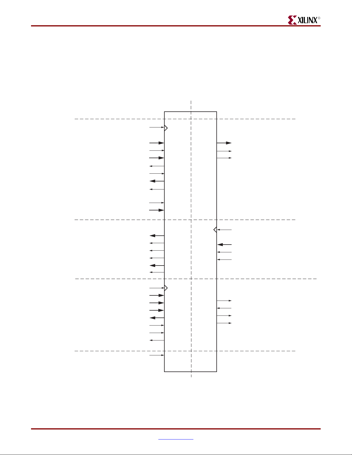
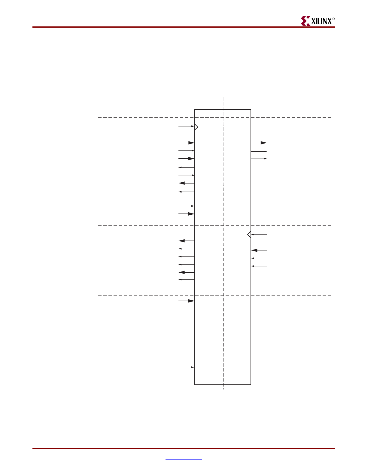
Figure 2-2 shows the pinout for the GEMAC core using the optional Management
Interface. The interface is unchanged, regardless of whether the optional Address Filter is
included.
Client Side Interface Physical Side Interface (GMII)
-- DISCONTINUED PRODUCT --
R
gtx_clk domain
tx_ifg_delay[7:0]
tx_statistics_vector[31:0]
tx_statistics_valid
pause_val[15:0]
gmii_rx_clk domain
rx_statistics_vector[27:0]
rx_statistics_valid
host_clk domain
host_opcode[1:0]
host_wr_data[31:0]
host_rd_data[31:0]
gtx_clk
tx_data[7:0]
tx_data_valid
tx_ack
tx_underrun
pause_req
rx_data[7:0]
rx_data_valid
rx_good_frame
rx_bad_frame
host_clk
host_addr[9:0]
host_miim_sel
host_req
host_miim_rdy
gmii_txd[7:0]
gmii_tx_en
gmii_tx_er
gmii_rx_clk
gmii_rxd[7:0]
gmii_rx_dv
gmii_rx_er
mdc
mdio_in
mdio_out
mdio_tri
reset
Figure 2-2: Component Pinout for MAC with Optional Management Interface
1-Gigabit Ethernet MAC v8.5 User Guide www.xilinx.com 23
UG144 April 24, 2009
Page 24
-- DISCONTINUED PRODUCT --
R
Chapter 2: Core Architecture
GMAC Core Without Management Interface and With Address Filter
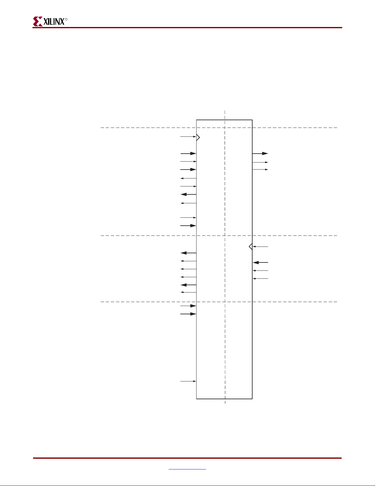
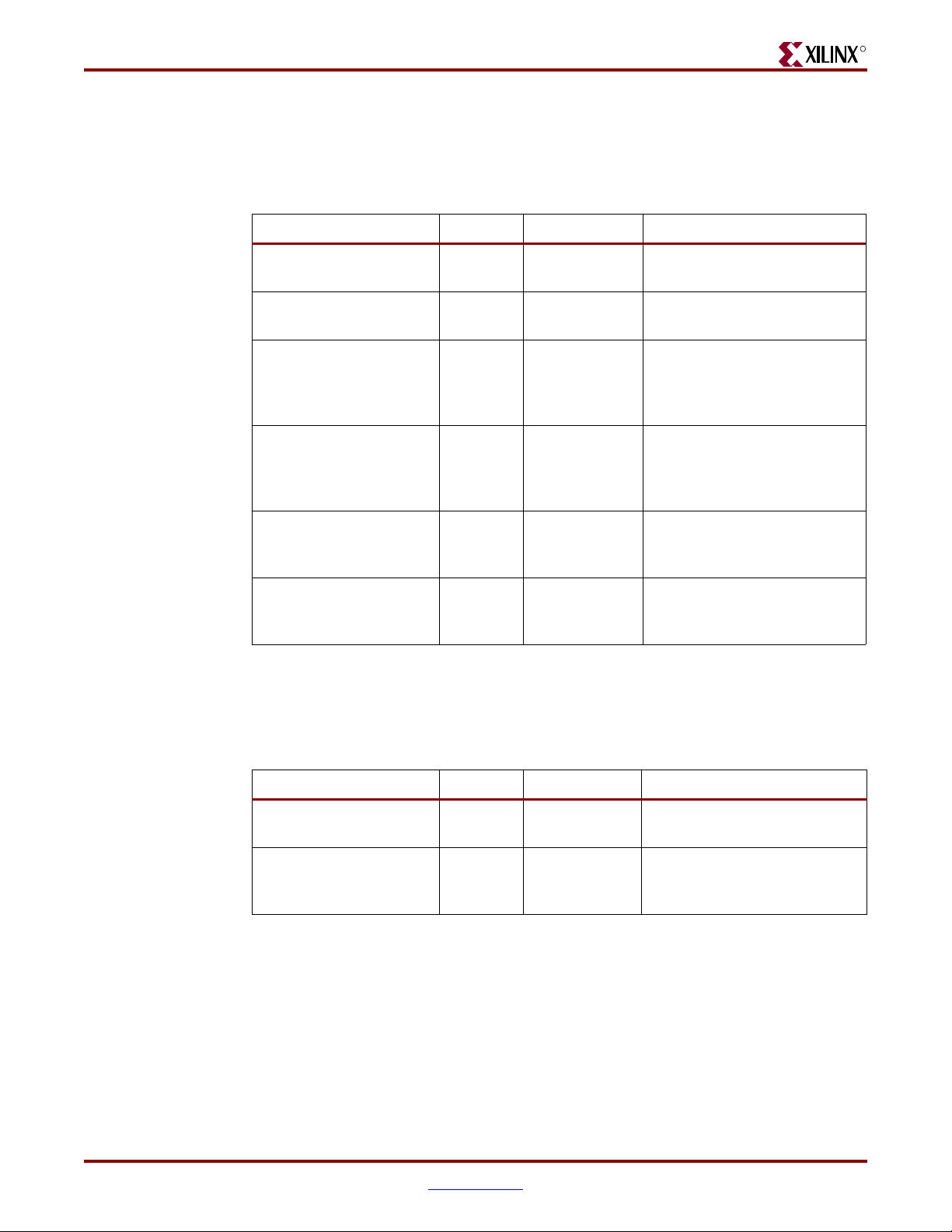
Figure 2-3 shows the pinout for the GEMAC core when the optional Management Interface
is omitted and the optional Address Filter is included in the core.
The configuration_vector[67:0] input provides the method for configuration of
the core, and mac_unicast_address[47:0] input provides the method of setting the
unicast address used by the Address Filter.
Client Side Interface Physical Side Interface (GMII)
gtx_clk domain
tx_data[7:0]
tx_data_valid
tx_ifg_delay[7:0]
tx_underrun
tx_statistics_vector[31:0]
tx_statistics_valid
pause_req
pause_val[15:0]
gmii_rx_clk domain
rx_data[7:0]
rx_data_valid
rx_good_frame
rx_bad_frame
rx_statistics_vector[27:0]
rx_statistics_valid
mac_unicast_address[47:0]
configuration_vector[67:0]
gtx_clk
gmii_txd[7:0]
gmii_tx_en
gmii_tx_er
tx_ack
gmii_rx_clk
gmii_rxd[7:0]
gmii_rx_dv
gmii_rx_er
reset
Figure 2-3: Component Pinout for MAC without Optional Management Interface
and with Optional Address Filter
24 www.xilinx.com 1-Gigabit Ethernet MAC v8.5 User Guide
UG144 April 24, 2009
Page 25
Core Interfaces
GEMAC Core Without Management Interface and Without Address Filter
-- DISCONTINUED PRODUCT --
R
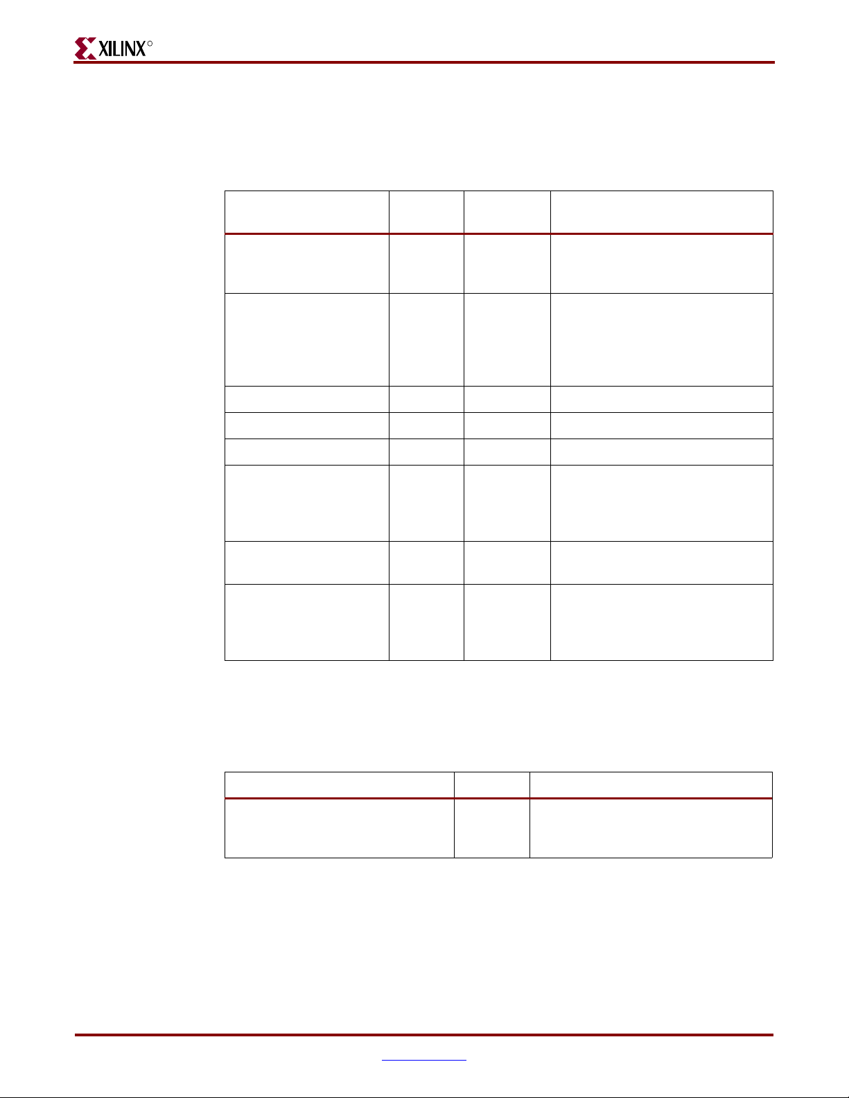
Figure 2-4 shows the pinout for the GEMAC core when the optional Management Interface
is omitted and the optional Address Filter is omitted.
The configuration_vector[67:0] input provides the method for configuration of
the core.
Client Side Interface Physical Side Interface (GMII)
gtx_clk domain
tx_ifg_delay[7:0]
tx_statistics_vector[31:0]
tx_statistics_valid
pause_val[15:0]
gmii_rx_clk domain
rx_data_valid
rx_good_frame
rx_bad_frame
rx_statistics_vector[27:0]
rx_statistics_valid
gtx_clk
tx_data[7:0]
tx_data_valid
tx_ack
tx_underrun
pause_req
rx_data[7:0]
gmii_txd[7:0]
gmii_tx_en
gmii_tx_er
gmii_rx_clk
gmii_rxd[7:0]
gmii_rx_dv
gmii_rx_er
configuration_vector[67:0]
reset
Figure 2-4: Component Pinout for MAC without Optional Management Interface or Optional Address Filter
1-Gigabit Ethernet MAC v8.5 User Guide www.xilinx.com 25
UG144 April 24, 2009
Page 26

R
All ports of the core are internal connections in FPGA fabric. An HDL example design is
delivered with the core that will add IBUFs, OBUFs, and IOB flip-flops to the external
signals of the Gigabit Media Independent Interface (GMII) or Reduced Gigabit Media
Independent Interface (RGMII).
All clock management logic is placed in this example design, which allows for more
flexibility in implementation (for example, in designs using multiple cores). This example
design is provided in both VHDL and Verilog. For more information about example
designs, see the 1-Gigabit Ethernet MAC Getting Started Guide.
Client Side Interface
Transmitter Interface
Tab le 2- 1 describes the client-side transmitter signals of the GEMAC core. These signals are
used to transmit data from the client logic into the core. See “Transmitting Outbound
Frames,” on page 47.
The Transmitter Interface is designed to be connected to internal device logic only.
Attempting to add external ports to this interface will result in a breakdown of the
handshaking protocol used by this interface.
-- DISCONTINUED PRODUCT --
Chapter 2: Core Architecture
Table 2-1: Transmitter Client Interface Signal Pins
Signal Direction
Clock
Domain
Description
gtx_clk Input n/a Clock signal provided to the core at
125 MHz. Tolerance must be
within IEEE 802.3-2005
specification. This clock signal is
used by all of the transmitter logic.
tx_data[7:0] Input gtx_clk Frame data to be transmitted is
supplied on this port.
tx_data_valid Input gtx_clk Control signal for tx_data port.
tx_ifg_delay[7:0] Input gtx_clk Control signal for configurable
Inter Frame Gap adjustment.
tx_ack Output gtx_clk Handshaking signal asserted when
the current data on tx_data has
been accepted.
tx_underrun Input gtx_clk Asserted by clien t to fo rce GEMA C
core to corrupt the current frame.
tx_statistics_vector[31:0] Output gtx_clk Provides statistical information
about the last frame transmitted.
tx_statistics_valid Output gtx_clk Asserted at end of frame
transmission, indicating that the
tx_statistics_vector is valid.
26 www.xilinx.com 1-Gigabit Ethernet MAC v8.5 User Guide
UG144 April 24, 2009
Page 27
Core Interfaces
-- DISCONTINUED PRODUCT --
R
Receiver Interface
Tab le 2- 2 describes the client-side receiver signals of the GEMAC core. These signals are
used by to transfer data to the client. See “Receiving Inbound Frames,” on page 39.
Table 2-2: Receive Client Interface Signal Pins
Signal Direction Clock Domain Description
rx_data[7:0] Output gmii_rx_clk Frame data received is
supplied on this port.
rx_data_valid Output gmii_rx_clk Control signal for the rx_data
port.
rx_good_frame Output gmii_rx_clk Asserted at end of frame
reception to indicate that the
frame should be processed by
the MAC client.
rx_bad_frame Output gmii_rx_clk Asserted at end of frame
reception to indicate that the
frame should be discarded by
the MAC client.
rx_statistics_vector[27:0] Output gmii_rx_clk Provides statistical
information about the last
frame received.
rx_statistics_valid Output gmii_rx_clk Asserted at end of frame
reception, indicating that the
rx_statistics_vector is valid.
Flow Control Interface
Tab le 2- 3 describes the signals used by the client to request a flow control action from the
transmit engine. See “Using Flow Control,” on page 53.
Table 2-3: Flow Control Interface Signal Pinout
Signal Direction Clock Domain Description
pause_req Input gtx_clk Pause request. sends a pause
frame down the link.
pause_val[15:0] Input gtx_clk Pause value; inserted into the
parameter field of the
transmitted pause frame.
1-Gigabit Ethernet MAC v8.5 User Guide www.xilinx.com 27
UG144 April 24, 2009
Page 28
-- DISCONTINUED PRODUCT --
R
Management Interface (Optional)
Tab le 2- 4 describes the optional signals used by the client to access the management
features of the GEMAC core. See “Using the Optional Management Interface,” on page 77.
Table 2-4: Optional Management Interface Signal Pinout
Chapter 2: Core Architecture
Signal Direction
Clock
Domain
Description
host_clk Input n/a Clock for the Management
Interface; must be 10 MHz or
above.
host_opcode[1:0] Input host_clk Defines operation to be performed
over MDIO interface. Bit 1 is also
used as a read/write control
signal for configuration register
access.
host_addr[9:0] Input host_clk Address of register to be accessed.
host_wr_data[31:0] Input host_clk Data to write to register .
host_rd_data[31:0] Output host_clk Data read from register.
host_miim_sel Input host_clk When asserted, the MDIO
interface is accessed. When not
asserted, the configuration
registers are accessed.
host_req Input host_clk Used to signal a transaction on the
MDIO interface.
host_miim_rdy Output host_clk When high, the MDIO interface
has completed any pending
transaction and is ready for a new
transaction.
MAC Unicast Address (Optional)
Tab le 2- 5 describes the alternative method of access to the unicast address registers when
the optional Management Interface is not present.
Table 2-5: Optional MAC Unicast Address Signal Pinout
Signal Direction Description
mac_unicast_address[47:0] Input Used to assess the MAC unicast
address registers when the
Management Interface is not used
Note: All bits are registered on input but may be treated as asynchronous inputs.
28 www.xilinx.com 1-Gigabit Ethernet MAC v8.5 User Guide
UG144 April 24, 2009
Page 29
Core Interfaces
-- DISCONTINUED PRODUCT --
R
Configuration Vector (Optional)
Tab le 2- 6 describes the alternative to the optional Management Interface signals. The
Configuration Vector uses direct inputs to the core to replace the functionality of the MAC
configuration bits. See “Access without the Management Interface,” on page 90.
Table 2-6: Optional Configuration Vector Signal Pinout
Signal Direction Description
configuration_vector[67:0] Input Used to replace the functionality of
the MAC Configuration Registers
when the Management Interface is
not used
Note: All bits are registered on input but may be treated as asynchronous inputs.
Asynchronous Reset
Tab le 2- 7 describes the asynchronous reset signal for the entire core.
Table 2-7: Reset Signal
Signal Direction Clock Domain Description
reset Input n/a Asynchronous reset for entire core
Physical Side Interface
GMII
Tab le 2- 8 describes the GMII-style interface signals of the core. See Chapter 7, “Using the
Physical Side Interface.”
Table 2-8: GMII Interface Signal Pinout
Signal Direction Clock Domain Description
gmii_txd[7:0] Output gtx_clk Transmit data from MAC
gmii_tx_en Output gtx_clk Transmit control signal from MAC
gmii_tx_er Output gtx_clk Transmit control signal from MAC
gmii_rx_clk Input n/a Receive clock from external PHY (125
gmii_rxd[7:0] Input gmii_rx_clk Received data to MAC
gmii_rx_dv Input gmii_rx_clk Received control signal to MAC
MHz)
gmii_rx_er Input gmii_rx_clk Received control signal to MAC
1-Gigabit Ethernet MAC v8.5 User Guide www.xilinx.com 29
UG144 April 24, 2009
Page 30
R
MDIO Interface
-- DISCONTINUED PRODUCT --
Chapter 2: Core Architecture
Tab le 2- 9 describes the MDIO Interface signals. See “Using the MDIO interface,” on page
76.
Table 2-9: MDIO Interface Signal Pinout
Signal Direction
Clock
Domain
Description
mdc Output host_clk Management Clock: programmable
frequency derived from host_clk.
mdio_in
1
Input host_clk Input data signal for communication with
PHY configuration and status. Tie high if
unused.
mdio_out
1
Output host_clk Output data signal for communication
with PHY configuration and status.
mdio_tri
1
Output host_clk Tristate control for MDIO signals; 0 signals
that the value on mdio_out should be
asserted onto the MDIO bus.
1. mdio_in, mdio_out and mdio_tri can be connected to a Tri-state buffer to create a bi-directional mdio
signal suitable for connection to an external PHY.
30 www.xilinx.com 1-Gigabit Ethernet MAC v8.5 User Guide
UG144 April 24, 2009
Page 31
-- DISCONTINUED PRODUCT --
R
Generating the Core
The GEMAC core is generated through the Xilinx CORE Generator™ using a graphical
user interface (GUI). This chapter describes the GUI options used to generate and
customize the core.
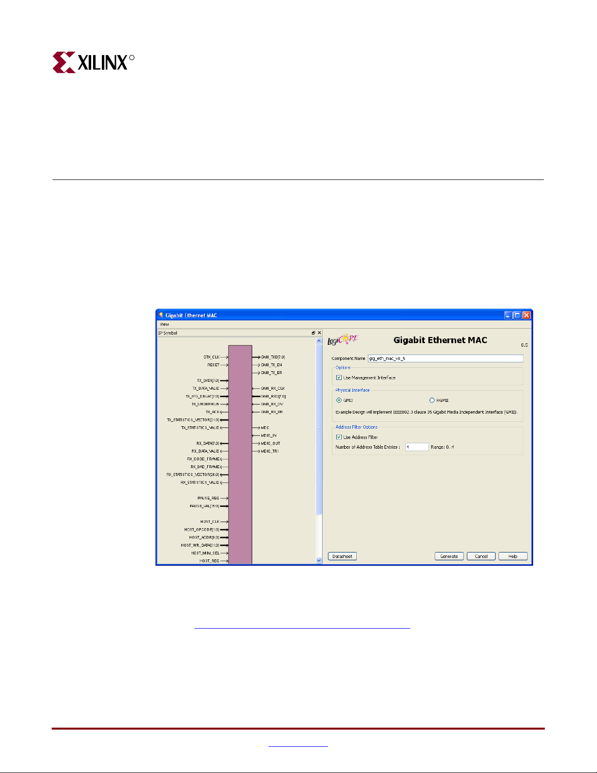
Graphical User Interface
Figure 3-1 shows the main GEMAC core user GUI screen.
Chapter 3
Figure 3-1: 1-Gigabit Ethernet MAC Main Screen
For general help starting and using CORE Generator on your system, see the
documentation supplied with the Xilinx ISE® software, including the CORE Generator
Guide at www.xilinx.com/support/software_manuals.htm
1-Gigabit Ethernet MAC v8.5 User Guide www.xilinx.com 31
UG144 April 24, 2009
.
Page 32

-- DISCONTINUED PRODUCT --
R
Component Name
The component name is used as the base name of the output files generated for the core.
Names must begin with a letter and must be composed from the following characters:
a through z, 0 through 9 and “_”.
Management Interface
Select this option to include the optional Management Interface (see “Using the Optional
Management Interface,” on page 77). If this option is not selected, the core is generated
with a replacement configuration vector (see “Access without the Management Interface,”
on page 90). The default is to use the Management Interface.
Address Filter
Select this option to include the optional Address Filter. This prevents the reception of
frames that are not addressed to this MAC (see “Address Filter,” on page 44). The default
is to use the Address Filter.
Chapter 3: Generating the Core
Number of Address Table Entries
The Address Filter can be instantiated with an address table that holds up to 4 additional
valid addresses. You may select an integer between 0 and 4 to define the number of
addresses that are present in the table.
This option is only available when the Management Interface and Address Filter have been
selected. The default is to use 4 address table entries.
Physical Interface
Depending on the target Xilinx FPGA architecture, it may be possible to select from two
different physical interface choices for the core:
• GMII. See Chapter 7, “Implementing External GMII”
• RGMII. See Chapter 7, “Implementing External RGMII”
The choice of physical interface determines the content of the example design delivered
with the core. The external GMII or RGMII is added in the HDL top-level design file. There
is no change in the core netlist for this option. The default is the GMII physical interface.
Parameter Values in the XCO File
XCO file parameter names and their values are identical to the names and values shown in
the GUI, except that underscore characters (_) are used instead of spaces. The text in an
XCO file is not case-sensitive.
Tab le 3- 1 defines the XCO file parameters and values and summarizes the GUI defaults.
The following is an example of the CSET parameters in an XCO file.
CSET component_name = abc123
CSET physical_interface = gmii
CSET management_interface = true
CSET address_filter = true
CSET no_of_address_table_entries = 4
32 www.xilinx.com 1-Gigabit Ethernet MAC v8.5 User Guide
UG144 April 24, 2009
Page 33

Output Generation
-- DISCONTINUED PRODUCT --
R
Table 3-1: XCO File Values and Default Values
Parameter XCO File Values Default GUI Setting
component_name ASCII text starting with a letter and
physical_interface One of the following keywords: gmii,
management_interface One of the following keywords: true,
address_filter One of the following keywords: true,
no_of_address_table_
entries
Output Generation
The output files generated from the CORE Generator tool are placed in the CORE
Generator project directory. The list of output files includes the following items.
• Netlist file for the core
• Supporting CORE Generator files
• Release notes and documentation
• Subdirectories containing an HDL example design
• Scripts to run the core through the back-end tools and to simulate the core using either
Mentor Graphics ModelSim, Cadence IUS or Synopsys VCS simulators.
gig_eth_mac_v8_5
based upon the following character
set: a..z, 0..9 and _
gmii
rgmii
true
false
true
false
Integer in the range 0 - 4 4
See the 1-Gigabit Ethernet MAC Getting Started Guide for more information about the CORE
Generator output files and for details on the HDL example design.
1-Gigabit Ethernet MAC v8.5 User Guide www.xilinx.com 33
UG144 April 24, 2009
Page 34

-- DISCONTINUED PRODUCT --
R
Chapter 3: Generating the Core
34 www.xilinx.com 1-Gigabit Ethernet MAC v8.5 User Guide
UG144 April 24, 2009
Page 35

-- DISCONTINUED PRODUCT --
R
Designing with the Core
This chapter provides general guidelines for creating designs using the GEMAC core. To
work with the example design included with the GEMAC core, see the 1-Gigabit Ethernet
MAC Getting Started Guide.
General Design Guidelines
This section describes the steps required to turn a GEMAC core into a fully functioning
design integrated with user-application logic. Not all implementations require all the
design steps described in this chapter. The following sections discuss the design steps
required for various implementations. For best results, carefully follow the logic design
guidelines.
Chapter 4
Design Steps
Generate the core from the Xilinx CORE Generator™. See Chapter 3, “Generating the
Core.”
Using the Example Design as a Starting Point
The GEMAC core is delivered through the CORE Generator with an HDL example design
built around the core, allowing the functionality of the core to be demonstrated using
either a simulation package or in hardware, if placed on a suitable board. Figure 4-1 is a
block diagram of the example design. For more information about the example design, see
the 1-Gigabit Ethernet MAC Getting Started Guide.
The example design illustrates how to:
• Instantiate the core from HDL.
• Source and use the client-side interface ports of the core from application logic.
• Connect the physical-side interface of the core (GMII or RGMII) to device IOBs
• Derive the clock management logic, as described in Chapter 10, “Clocking and
creating an external interface. (See Chapter 7, “Using the Physical Side Interface.”)
Resetting.”
1-Gigabit Ethernet MAC v8.5 User Guide www.xilinx.com 35
UG144 April 24, 2009
Page 36

-- DISCONTINUED PRODUCT --
R
Chapter 4: Designing with the Core
<component_name>_example_design
<component_name>_locallink
Clock/
Reset
Circuitry
10 Mbps, 100 Mbps
1 Gbps Ethernet FIFO
Tx Client
FIFO
Address
Swap
Module
LocalLink Interface
Rx Client
FIFO
<component_name>_block
1-Gigabit Ethernet
MAC Core
Client
Interface
Management
Interface
Statistics Vectors
Interface
Physical
Interface
GMII/ RGMII
Management
Figure 4-1: 1-Gigabit Ethernet MAC Core Example Design
Using the example design as a starting point, you can do the following:
Interface
Logic,
IOBs and
Clock
• Edit the HDL top level of the example design file to:
♦ Change the clocking scheme.
♦ Add/remove IOBs as required.
♦ Replace the client loopback logic with your specific application logic.
♦ Adapt the 10 Mbps, 100 Mbps, 1 Gbps Ethernet FIFO to suit your specific
application (see “Using the Client-Side FIFO”).
• Synthesize the entire design.
The Xilinx Synthesis Tool (XST) script and Project file in the /implement directory
may be adapted to include any HDL files you may want to add.
• Run the implement script in the /implement directory to create a top-level netlist for
the design. The script may also run the Xilinx tools map, par, and bitgen, creating a
bitstream that can be downloaded to a Xilinx device. SimPrim-based simulation
models for the entire design are also produced by the implement scripts.
• Simulate the entire design using the demonstration test bench provided as a template
in the /simulation directory.
• Download the bitstream to a target device.
36 www.xilinx.com 1-Gigabit Ethernet MAC v8.5 User Guide
UG144 April 24, 2009
Page 37

General Design Guidelines
Implementing the 1-Gigabit Ethernet MAC in Your Application
The example design can be studied as an example of how to do the following:
• Instantiate the core from HDL.
• Source and use the client-side interface ports of the core from application logic.
• Connect the physical-side interface of the core (GMII or RGMII) to device IOBs to
• Derive the clock management logic.
After working with the example design, you can write your own HDL application, using
single or multiple instances of the GEMAC core. Client-side interfaces and operation of the
core are detailed later in this chapter. For more information, see:
• Clock Management Logic in Chapter 10, “Clocking and Resetting.”
• Using the GEMAC core in conjunction with the Ethernet 1000BASE-X PCS/PMA or
• Using the GEMAC core in conjunction with the Ethernet Statistics core in Chapter 11,
• 10 Mbps, 100 Mbps, 1 Gbps Ethernet FIFO in Appendix A, “Using the Client-Side
-- DISCONTINUED PRODUCT --
R
create an external interface.
SGMII core in Chapter 11, “Interfacing to Other Cores.”
“Interfacing to Other Cores”
FIFO.”
You can synthesize the entire design using any synthesis tool. The GEMAC core is presynthesized and is delivered as an NGC netlist (which appears as a black box to synthesis
tools).
Run the Xilinx tools map, par, and bitgen to create a bitstream that can be downloaded to
a Xilinx device. Care must be taken to constrain the design correctly, and the UCF
produced by the CORE Generator should be used as the basis for the your own UCF. See
Chapter 9, “Constraining the Core,”.
You can simulate the entire design and download the bitstream to the target device.
Know the Degree of Difficulty
A 1-Gigabit Ethernet MAC implementation is challenging to implement in any technology,
and all applications require careful attention to system performance requirements.
Pipelining, logic mapping, placement constraints, and logic duplication are all methods
that help boost system performance.
See Tab le 4-1 to determine the relative level of difficulty associated with the Spartan® and
Virtex® device families. These designs relate to meeting the core required system clock
frequency of 125 MHz.
1-Gigabit Ethernet MAC v8.5 User Guide www.xilinx.com 37
UG144 April 24, 2009
Page 38

R
See also Appendix C, “Calculating DCM Phase-Shifting” to meet Spartan-3, Spartan-3E
and Spartan-3A device setup and hold requirements for external GMII.
Table 4-1: Degree of Difficulty for Various Implementations
Spartan-3A/3AN/3A DSP platforms Difficult
Spartan-3E platform Difficult
Spartan-3 device Difficult
Virtex-4 device Easy
Virtex-5 device Easy
Keep it Registered
To simplify timing and increase system performance in an FPGA design, keep all inputs
and outputs registered between the user application and the core. This means that all
inputs and outputs from the user application should come from, or connect to, a flip-flop.
While registering signals may not be possible for all paths, it simplifies timing analysis and
makes it easier for the Xilinx tools to place-and-route the design.
-- DISCONTINUED PRODUCT --
Chapter 4: Designing with the Core
Device Family Difficulty
Recognize Timing Critical Signals
The UCF provided with the example design identifies the critical signals and timing
constraints that should be applied. See Chapter 9, “Constraining the Core”
Use Supported Design Flows
The core is pre-synthesized and delivered as an NGC netlist. The example implementation
scripts provided use XST 11.1 as the synthesis tool for the HDL example design. Other
synthesis tools may be used for the user application logic. The core is always unknown to
the synthesis tool and should appear as a black box. For post synthesis, only ISE® 11.1 tools
are supported.
Make Only Allowed Modifications
The GEMAC core should not be modified by you. Any modifications may have adverse
effects on system timing and protocol compliance. Supported user configurations of the
GEMAC core can only be made by selecting the options in the CORE Generator when the
core is generated. See Chapter 3, “Generating the Core.”
38 www.xilinx.com 1-Gigabit Ethernet MAC v8.5 User Guide
UG144 April 24, 2009
Page 39
-- DISCONTINUED PRODUCT --
R
Using the Client Side Data Path
This chapter provides general guidelines for creating designs using the GEMAC core,
including a detailed description of each client-side data flow interface of the core.
Definitions of the abbreviations used throughout the remainder of this chapter are defined
in Tab le 5- 1.
Table 5-1: Abbreviations Used in Timing Diagrams
Abbreviation Definition
DA Destination address; 6 bytes
Chapter 5
SA Source address; 6 bytes
L/T Length/type field; 2 bytes
FCS Frame check sequence; 4 bytes
Receiving Inbound Frames
Received Ethernet frames are presented to the client logic on the Receiver subset of the
Client-Side Interface. For port definition, see “Receiver Interface,” on page 27.
Normal Frame Reception
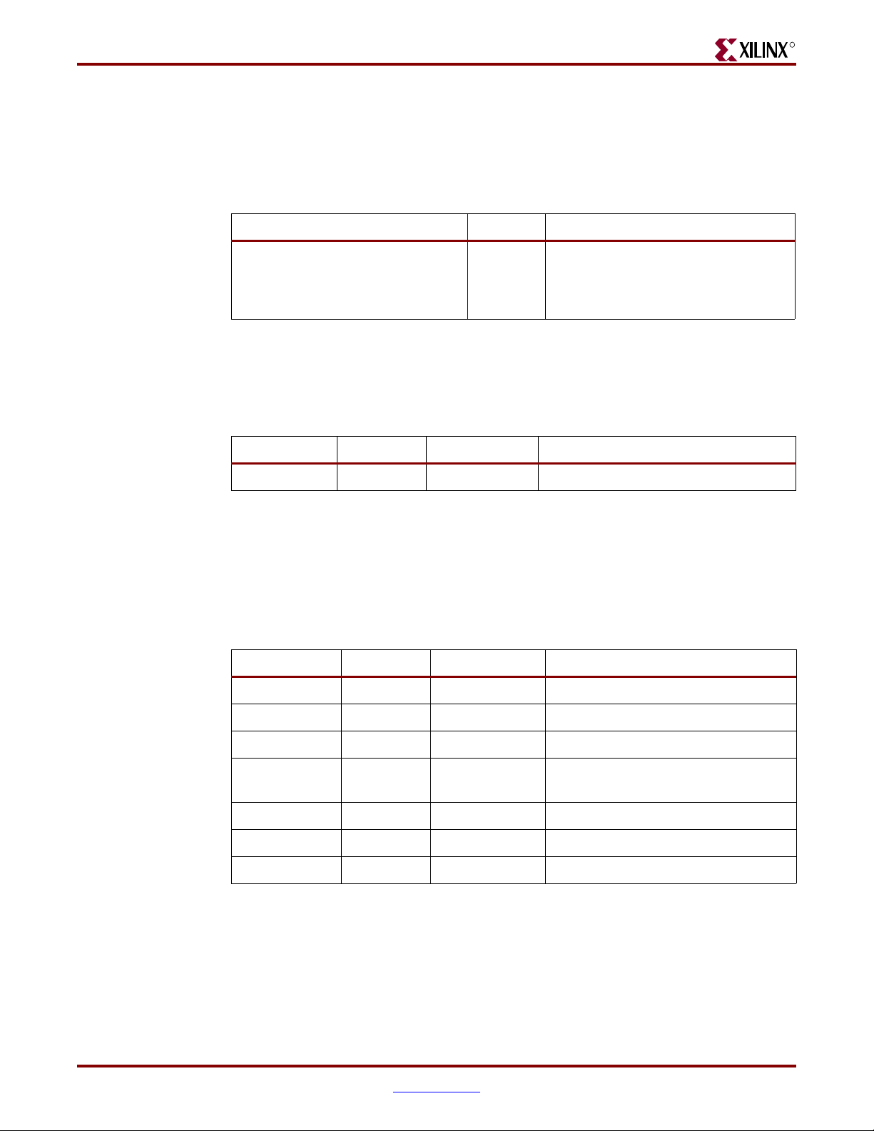
Figure 5-1 illustrates the timing of a normal inbound frame transfer. The client must be
prepared to accept data at any time; there is no buffering within the MAC to allow for
latency in the receive client. Once frame reception begins, data is transferred on
consecutive clock cycles to the receive client until the frame is complete. The MAC asserts
the rx_good_frame signal to indicate that the frame was successfully received and that
the frame should be analyzed by the client.
1-Gigabit Ethernet MAC v8.5 User Guide www.xilinx.com 39
UG144 April 24, 2009
Page 40

-- DISCONTINUED PRODUCT --
R
gmii_rx_clk
rx_data[7:0]
DA SA DATAL/T
rx_data_valid
rx_good_frame
rx_bad_frame
Chapter 5: Using the Client Side Data Path
Figure 5-1: Normal Frame Reception
Frame parameters (destination address, source address, length/type and optionally FCS)
are supplied on the data bus according to the timing diagram.
If the length/type field in the frame has a length interpretation, indicating that the
inbound frame has been padded to meet the Ethernet minimum frame size, the padding is
not passed to the client in the data payload. The exception to this is where FCS passing is
enabled. See “Client-Supplied FCS Passing.”
When Client-Supplied FCS passing is disabled, rx_data_valid is equal to zero between
frames for the duration of the padding field (if present), the FCS field, carrier extension (if
present), the interframe gap following the frame, and the preamble field of the next frame.
When Client-Supplied FCS passing is enabled, rx_data_valid is equal to zero between
frames for the duration of carrier extension (if present), the interframe gap, and the
preamble field of the following frame.
rx_good_frame, rx_bad_frame timing
Although the timing diagram (Figure 5-1) shows the rx_good_frame signal asserted
shortly after the last valid data on rx_data, this is not always the case. The
rx_good_frame or rx_bad_frame signals are asserted only after all frame checks are
completed. This is after the FCS field has been received (and after reception of carrier
extension, if present).
Therefore, either rx_good_frame or rx_bad_frame is asserted following frame
reception at the beginning of the interframe gap.
40 www.xilinx.com 1-Gigabit Ethernet MAC v8.5 User Guide
UG144 April 24, 2009
Page 41
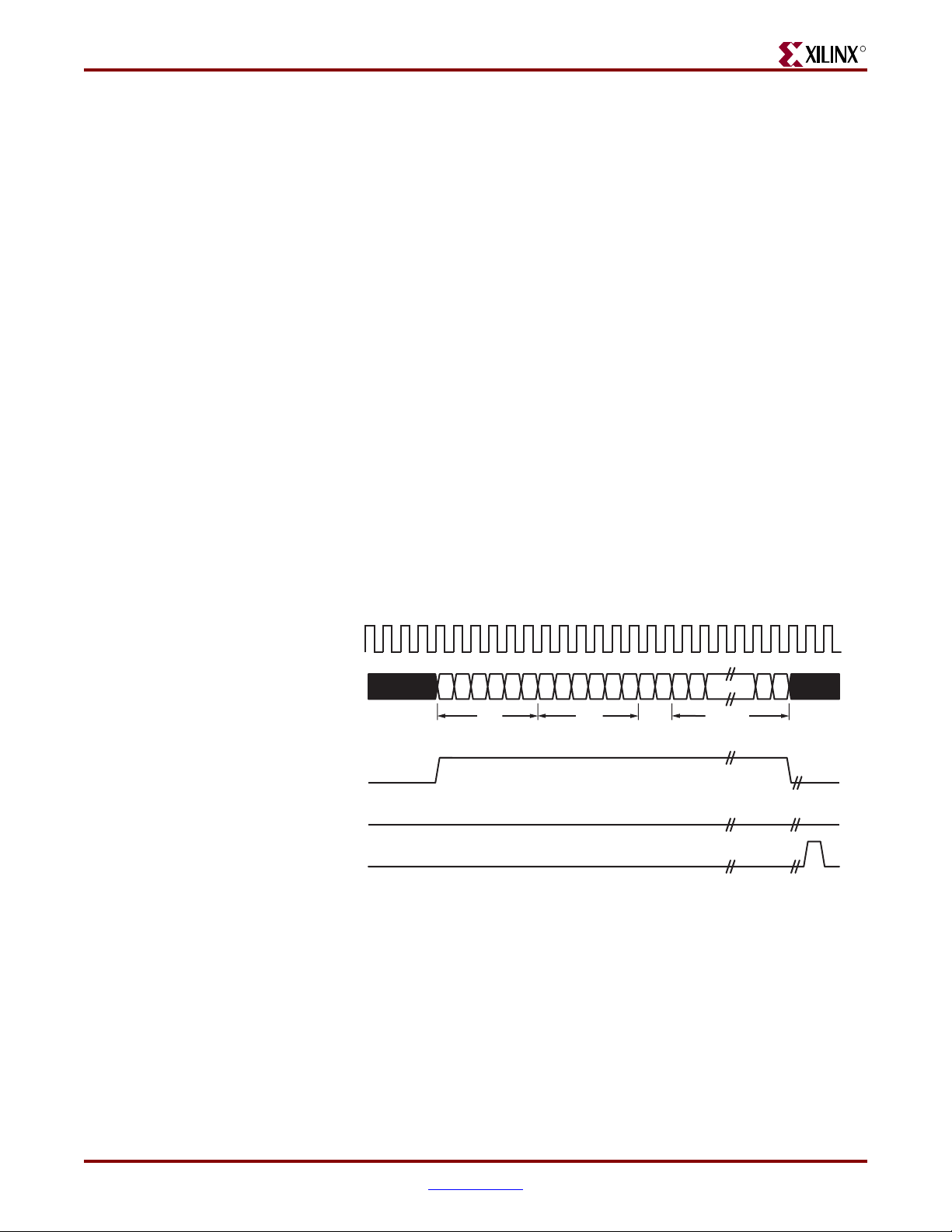
Receiving Inbound Frames
Frame Reception with Errors
Figure 5-2 illustrates an unsuccessful frame reception (for example, a fragment frame or a
frame with an incorrect FCS). In this case, the rx_bad_frame signal is asserted to the
client at the end of the frame. It is then the responsibility of the client to drop the data
already transferred for this frame.
The following conditions cause the assertion of rx_bad_frame:
• FCS errors occur.
• Packets are shorter than 64 bytes (undersize or fragment frames).
• Jumbo frames are received when jumbo frames are not enabled.
• VLAN frames of length 1519-1522 are received when VLAN frames are not enabled.
• A value of 0x0000 to 0x002D is in the type/length field. In this situation, the frame
• A value of 0x002E to 0x0600 is in the type/length field, but the real length of the
• Any control frame that is received is not exactly the minimum frame length (unless
• gmii_rx_er is asserted at any point during frame reception.
• An error code is received in the 1-Gigabit frame extension field.
• A valid pause frame, addressed to the MAC, is received when flow control is enabled.
-- DISCONTINUED PRODUCT --
R
should be padded to minimum length. If it is not padded to exactly minimum frame
length, the frame is marked as bad (when length/type checking is enabled).
received frame does not match this value (when length/type checking is enabled).
control frame length checks are disabled).
Please see “Overview of Flow Control,” on page 53.
gmii_rx_clk
rx_data[7:0]
rx_data_valid
rx_good_frame
rx_bad_frame
DA SA DATA
L/T
Figure 5-2: Frame Reception with Error
1-Gigabit Ethernet MAC v8.5 User Guide www.xilinx.com 41
UG144 April 24, 2009
Page 42

-- DISCONTINUED PRODUCT --
R
Client-Supplied FCS Passing
If the GEMAC core is configured to pass the FCS field to the client (see “Configuration
Registers,” on page 78), this is handled as shown in Figure 5-3. In this case, any padding
inserted into the frame to meet Ethernet minimum frame length specifications will be left
intact and passed to the client.
Even though the FCS is passed up to the client, it is also verified by the GEMAC core, and
rx_bad_frame asserted if the FCS check fails.
gmii_rx_clk
rx_data[7:0]
rx_data_valid
rx_good_frame
Chapter 5: Using the Client Side Data Path
DA SA DATA
L/T FCS
rx_bad_frame
VLAN Tagged Frames
Figure 5-4 illustrates the reception of a VLAN tagged frame (if enabled). The VLAN frame
is passed to the client so that the frame may be identified as VLAN tagged. This is followed
by the Tag Control Information bytes, V1 and V2. More information on the interpretation
of these bytes may be found in IEEE 802.3-2005 standard.
gmii_rx_clk
rx_data[7:0]
rx_data_valid
rx_good_frame
rx_bad_frame
Figure 5-3: Frame Reception with In-Band FCS Field
8100V1V2
DA SA DATAL/T
VLAN
tag
Figure 5-4: Reception of a VLAN Tagged Frame
42 www.xilinx.com 1-Gigabit Ethernet MAC v8.5 User Guide
UG144 April 24, 2009
Page 43

Receiving Inbound Frames
Maximum Permitted Frame Length
The maximum legal length of a frame specified in IEEE 802.3-2005 is 1518 bytes for nonVLAN tagged frames. VLAN tagged frames may be extended to 1522 bytes. When jumbo
frame handling is disabled and the core receives a frame which exceeds the maximum
legal length, rx_bad_frame is asserted. When jumbo frame handling is enabled, frames
which are longer than the legal maximum are received in the same way as shorter frames.
For more information about enabling and disabling jumbo frame handling, see
“Configuration Registers,” on page 78.
Length/Type Field Error Checks
Enabled
Default operation is with the length/type error checking enabled (see “Receiver
Configuration,” on page 79). In this mode, the following checks are made on all frames
received. If either of these checks fail, the frame is marked as bad.
• A value in the length/type field that is greater than or equal to decimal 46, but less
• A value in the length/type field that is less than decimal 46 is checked to see that the
-- DISCONTINUED PRODUCT --
R
than decimal 1536 (a length interpretation), is checked against the actual data length
received.
data field is padded to exactly 46 bytes (so that the resultant frame is a minimum
frame size of 64 bytes total in length).
Furthermore, if padding is indicated (the length/type field is less than decimal 46) and
client-supplied FCS passing is disabled, the length value in the length/type field will be
used to deassert rx_data_valid after the indicated number of data bytes so that the
padding bytes are removed from the frame. See “Client-Supplied FCS Passing.”
Disabled
When the length/type error checking is disabled and the length/type field has a length
interpretation, the MAC does not check the length value against the actual data length
received. See “Receiver Configuration” in Chapter 8. A frame containing only this error is
marked as good.
However, if the length/type field is less than decimal 46 then the MAC will mark a frame
as bad if it is not the minimum frame size of 64 bytes.
If padding is indicated and client-supplied FCS passing is disabled, then a length value in
the length/type field will not be used to deassert rx_data_valid. Instead,
rx_data_valid is deasserted before the start of the FCS field, and any padding is not
removed from the frame.
1-Gigabit Ethernet MAC v8.5 User Guide www.xilinx.com 43
UG144 April 24, 2009
Page 44

R
Address Filter
If the optional Address Filter is included in the core, the MAC is able to reject frames that
do not contain a known address in their destination address field. If a frame is rejected, the
rx_data_valid signal is not asserted for the duration of the frame. In addition, neither
rx_good_frame or rx_bad_frame are asserted at the end of the frame. The statistics
vectors are still output with a valid pulse at the end of the rejected frame.
If the Address Filter is not in promiscuous mode, it will reject frames in which the
destination address does not meet any of the following criteria:
• It is equal to the broadcast address defined in the IEEE 802.3-2005 specification.
• It is equal to the pause multicast address defined in the IEEE 802.3-2005 specification.
• The destination address field contains the pause frame MAC source address specified
in the Receiver Configuration Word 0 and Word 1.
• It is equal to the MAC unicast address. When the optional Management Interface is
present, this is found in the unicast address configuration registers (Tab le 8 -8 and
Tabl e 8-9 , pag e 82 ). If the Management Interface is not present the unicast address is
input on the mac_unicast_address input.
• It matches any of the addresses stored in the MAC address table. The address table is
only present when the MAC contains the optional Management Interface and the core
was built with one or more address table entries.
-- DISCONTINUED PRODUCT --
Chapter 5: Using the Client Side Data Path
Receiver Statistics Vector
The statistics for the frame received are contained within the rx_statistics_vector.
The vector is driven synchronously by the receiver clock, gmii_rx_clk, following frame
reception. The bit field definition for the vector is defined in Tab le 5-2 .
All bit fields, with the exception of byte valid, are valid only when the
rx_statistics_valid is asserted. This is illustrated in Figure 5-5. Byte valid is
significant on every gmii_rx_clk cycle.
Caution!
Ethernet MAC core. They are not backwards compatible with previous versions of the 1-Gigabit
Ethernet MAC core (see Ta bl e 5 -3 for Receiver Statistic Vector conversion details)
The statistic vectors in this release have been made compatible with the Tri-Mode
rx_statistics_valid
rx_statistics_vector[27:0]
Figure 5-5: Receiver Statistics Vector Timing
gmii_rx_clk
44 www.xilinx.com 1-Gigabit Ethernet MAC v8.5 User Guide
UG144 April 24, 2009
Page 45

Receiving Inbound Frames
Table 5-2: Bit Definition for the Receiver Statistics Vector
-- DISCONTINUED PRODUCT --
R
rx_statistics_vector
bit(s)
Name Description
27 Address Match If the optional Address Filter is included in the
core, this bit is asserted if the address of the
incoming frame matches one of the stored or
pre-set addresses in the Address Filter. If the
Address Filter is omitted from the core, or is
configured in promiscuous mode, this line is
held high.
26 Reserved Always at logic 0.
25 Length/Type
Out of Range
If the length/type field contained a length
value that did not match the number of MAC
client data bytes received and the length/type
field checks are enabled, then this bit is
asserted.
This bit is also asserted if the length/type field
is less than 46 and the frame is not padded to
exactly 64 bytes. This is independent of
whether or not the length/type field checks
are enabled.
24 Bad Opcode Asserted if the previous frame was error-free
and contained the special control frame
identifier in the length/type field, but
contained an opcode that is unsupported by
the MAC (any opcode other than Pause).
23 Flow Control
Frame
Asserted if the previous frame met all the
following conditions:
• error-free
• contained the special control frame
identifier in the length/type field
• contained a destination address that
matched either the MAC Control Multicast
Address or the configured source address
of the MAC
• contained the supported Pause opcode
• was acted upon by the MAC
22 Byte Valid Asserted if a MAC frame byte (DA to FCS
inclusive) is in the process of being received.
This is valid on every clock cycle.
Do not use this as an enable signal to indicate
that data is present on rx_data.
21 VLAN frame Asserted if the previous frame contained a
VLAN identifier in the length/type field when
receiver VLAN operation is enabled.
1-Gigabit Ethernet MAC v8.5 User Guide www.xilinx.com 45
UG144 April 24, 2009
Page 46

-- DISCONTINUED PRODUCT --
R
Chapter 5: Using the Client Side Data Path
Table 5-2: Bit Definition for the Receiver Statistics Vector
rx_statistics_vector
bit(s)
Name Description
20 Out of Bounds Asserted if the previous frame exceeded the
specified IEEE802.3-2005 maximum legal
length (see “Maximum Permitted Frame
Length”). This is only valid if jumbo frames
are disabled.
19 Control Frame Asserted if the previous frame contained the
special control frame identifier in the
length/type field.
18:5 Frame Length The length of the previous frame in number of
bytes. The count will stick at 16,383 for any
jumbo frames larger than this value.
4 Multicast Frame Asserted if the previous frame contained a
multicast address in the destination address
field.
3 Broadcast Frame Asserted if the previous frame contained the
broadcast address in the destination address
field.
2 FCS Error Asserted if the previous frame received had an
incorrect FCS value or the MAC detected error
codes during frame reception.
1 Bad Frame Asserted if the previous frame received
contained errors.
0 Good Frame Asserted if the previous frame received was
error-free.
Tab le 5- 3 provides conversion information against previous versions of the GEMAC.
Table 5-3: Rx Statistics conversion to previous core GEMAC core versions
Version 8.5
rx_statistics_vector
bit(s)
Version 8.4 (and earlier)
rx_statistics_vector
bit(s)
Notes
27 26 Bit 27 is equivalent to bit 26
of all previous core
versions.
26 N/A Bit 26 (reserved) has been
inserted into version 8.5 for
statistic vector
compatibility with the TriMode Ethernet MAC
LogiCORE™.
25:0 25:0 No differences
46 www.xilinx.com 1-Gigabit Ethernet MAC v8.5 User Guide
UG144 April 24, 2009
Page 47

-- DISCONTINUED PRODUCT --
Transmitting Outbound Frames
Transmitting Outbound Frames
Ethernet frames to be transmitted are presented to the client logic on the Transmitter subset
of the Client-Side Interface. For port definition, see “Transmitter Interface,” on page 26.
Normal Frame Transmission
Figure 5-6 illustrates the timing of a normal outbound frame transfer. When the client
wishes to transmit a frame, it places the first column of data onto the tx_data port and
asserts a ‘1’ onto tx_data_valid.
When the GEMAC core has read this first byte of data, and in accordance with flow control
requests and interpacket gap requirements, it will assert the tx_ack signal; on the next
and subsequent rising clock edges, the client must provide the remainder of the data for
the frame.
The end of frame is signalled to the GEMAC core by taking tx_data_valid low.
For maximum flexibility in switching and routing applications, the Ethernet frame
parameters (destination address, source address, length/type and optionally FCS) are
encoded within the same data stream that the frame payload is transferred upon, rather
than on separate ports. This is illustrated in the timing diagrams. Definitions of the
abbreviations used in the timing diagrams are defined in Tab le 5- 1.
R
Padding
gtx_clk
tx_data[7:0]
DA SA DATAL/T
tx_data_valid
tx_ack
tx_underrun
Figure 5-6: Normal Frame Transmission
When fewer than 46 bytes of data are supplied by the client to the GEMAC core, the
transmitter module will add padding up to the minimum frame length. The exception to
this is when the GEMAC core is configured for client-passed FCS; in this case, the client
must also supply the padding to maintain the minimum frame length. See “Client-
Supplied FCS Passing” for more information.
1-Gigabit Ethernet MAC v8.5 User Guide www.xilinx.com 47
UG144 April 24, 2009
Page 48
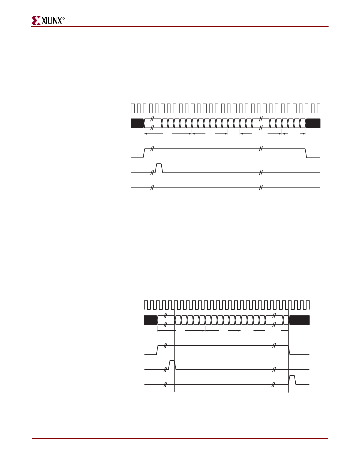
-- DISCONTINUED PRODUCT --
R
Client-Supplied FCS Passing
The transmission timing depicted in Figure 5-7 shows the GEMAC core configured to have
the FCS field passed in by the client. In this case, it is the responsibility of the client to
ensure that the frame meets the Ethernet minimum frame length requirements as the
GEMAC core will not perform any padding of the payload. See “Configuration Registers,”
on page 78.
gtx_clk
tx_data[7:0]
Chapter 5: Using the Client Side Data Path
tx_data_valid
tx_ack
tx_underrun
Client Underrun
Figure 5-8 illustrates the timing of an aborted transfer. An example of this situation is a
FIFO connected to the client interface that empties before a frame transfer is complete.
When the client asserts tx_underrun during a frame transmission, the GEMAC core
inserts an error code to corrupt the current frame, and then falls back to idle transmission.
It is the responsibility of the client to re-queue the aborted frame for transmission.
When an underrun occurs, tx_data_valid may be asserted on the clock cycle after the
tx_underrun assertion to request a new transmission.
DA SA DATA FCS
L/T
Figure 5-7: Frame Transmission with Client-supplied FCS
gtx_clk
tx_data[7:0]
DA S A DATA
tx_data_valid
tx_ack
tx_underrun
L/T
Figure 5-8: Frame Transmission with Underrun
48 www.xilinx.com 1-Gigabit Ethernet MAC v8.5 User Guide
UG144 April 24, 2009
Page 49

Transmitting Outbound Frames
VLAN Tagged Frames
Figure 5-9 illustrates transmission of a VLAN tagged frame (if enabled). The handshaking
signals across the interface do not change; however, the VLAN type tag 81-00 must be
supplied by the client to signify that the frame is VLAN tagged. The client also supplies the
two bytes of Tag Control Information, V1 and V2, at the appropriate times in the data
stream. More information on the contents of these two bytes can be found in IEEE 802.3-
2005. For more information about enabling and disabling jumbo frame handling, see
“Configuration Registers,” on page 78.
gtx_clk
-- DISCONTINUED PRODUCT --
R
tx_data[7:0]
DA S A DATA
tx_data_valid
tx_ack
tx_underrun
Figure 5-9: Transmission of a VLAN Tagged Frame
Maximum Permitted Frame Length
The maximum legal length of a frame specified in IEEE 802.3-2005 is 1518 bytes for nonVLAN tagged frames. VLAN tagged frames may be extended to 1522 bytes. When jumbo
frame handling is disabled and the client attempts to transmit a frame that exceeds the
maximum legal length, the GEMAC core will insert an error code to corrupt the current
frame, and the frame will be truncated to the maximum legal length. When jumbo frame
handling is enabled, frames longer than the legal maximum are transmitted error-free. For
more information on enabling and disabling Jumbo frame handling, see “Configuration
Registers,” on page 78.
81 00 V1
tag
V
2
L/TVLAN
Inter-Frame Gap Adjustment
A configuration bit in the transmitter control register (see “Configuration Registers,” on
page 78) allows you to control the length of the inter-frame gap transmitted by the MAC on
the physical interface. If this function is selected, the MAC exerts back pressure on the
client interface to delay the transmission of the next frame until the requested number of
idle cycles has elapsed. The number of idle cycles is controlled by the value on the
tx_ifg_delay port seen at the start of frame transmission on the client interface.
Figure 5-10 shows the MAC operating in this mode.
Reducing the interframe gap to below the IEEE 802.3-2005 minimum of 12 idles is
supported, but the MAC will transmit an absolute minimum of 4 idles. If the Ethernet
Statistics core is used with the MAC, then accuracy cannot be guaranteed if the interframe
gap adjustment is set to less than 12 idles. However, the tx_statistic_vector and
rx_statistic_vector values will always remain correct.
1-Gigabit Ethernet MAC v8.5 User Guide www.xilinx.com 49
UG144 April 24, 2009
Page 50
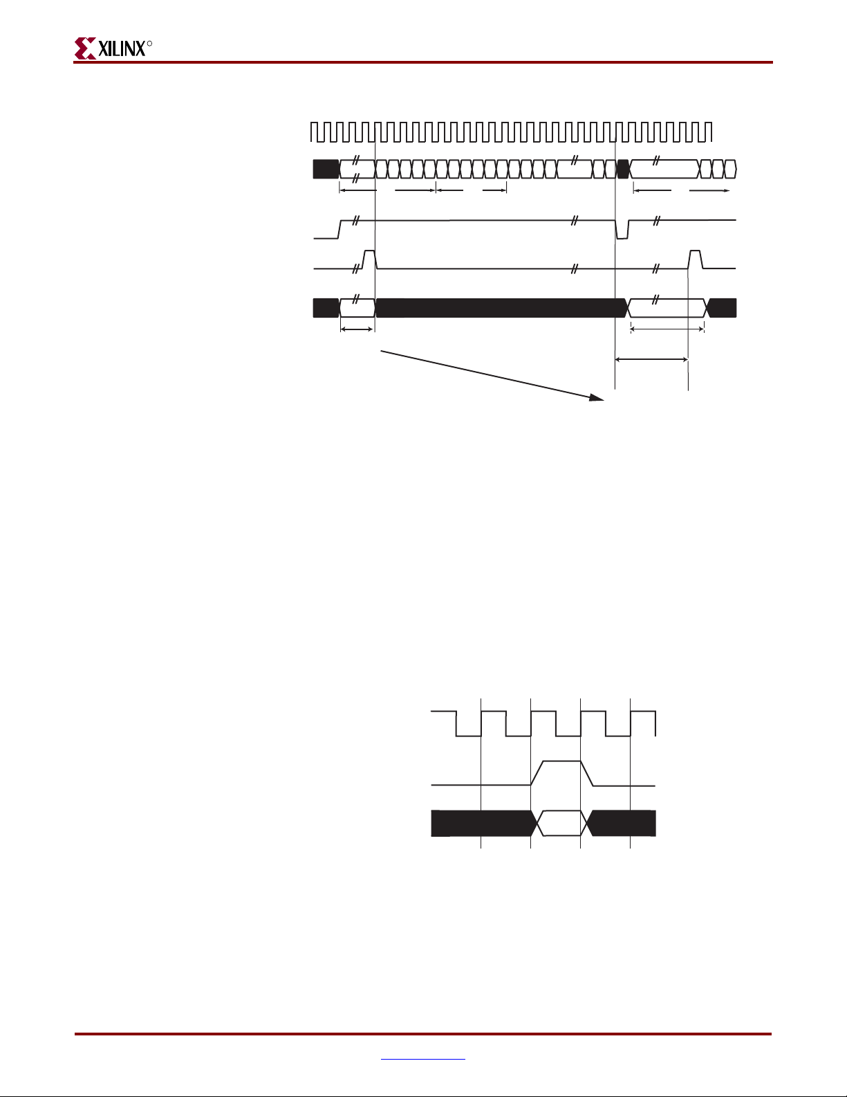
-- DISCONTINUED PRODUCT --
R
gtx_clk
tx_data[7:0]
DA
tx_data_valid
tx_ack
Chapter 5: Using the Client Side Data Path
SA
DA
tx_ifg_delay
0x0D
IFG ADJUST VALUE
Figure 5-10: Inter-Frame Gap Adjustment
Transmitter Statistics Vector
The statistics for the transmitted frame are contained within the tx_statistic_vector.
The vector is driven synchronously by the transmitter clock, gtx_clk, following frame
transmission. The bit field definition for the vector is defined in Tab le 5- 4.
All bit fields, with the exception of byte valid, are valid only when
tx_statistic_valid is asserted (Figure 5-11). Byte valid is significant on every
gtx_clk cycle.
Caution!
Ethernet MAC core. They are not backwards compatible with previous versions of the 1-Gigabit
Ethernet MAC core (see Ta bl e 5 -5 for Transmitter Statistic Vector conversion details).
The statistic vectors in this release have been made compatible with the Tri-Mode
Next IFG ADJUST VALUE
13 Idles inserted between the
end of frame and the preamble
field of the following frame
gtx_clk
tx_statistic_valid
tx_statistic_vector[31:0]
Figure 5-11: Transmitter Statistic Vector Timing
50 www.xilinx.com 1-Gigabit Ethernet MAC v8.5 User Guide
UG144 April 24, 2009
Page 51

Transmitting Outbound Frames
Table 5-4: Bit Definition for the Transmitter Statistics Vector
tx_statistics_vector
31 Pause Frame Asserted if the previous frame was a pause
30 Byte Valid Asserted if a MAC frame byte (DA to FCS
29:20 Reserved Always at logic 0.
19 VLAN Frame Asserted if the previous frame contained a
-- DISCONTINUED PRODUCT --
R
bit(s) Name Description
frame that the MAC itself initiated in
response to a pause_req assertion.
inclusive) is in the process of being
transmitted. This is valid on every clock
cycle.
Do not use this as an enable signal to
indicate that data is present on gmii_txd.
VLAN identifier in the length/type field
when transmitter VLAN operation is
enabled.
18:5 Frame Length The length of the previous frame in number
of bytes. The count will stick at 16,383 for
any jumbo frames larger than this value.
4 Control Frame Asserted if the previous frame had the
special MAC Control Type code 88-08 in the
length/type field.
3 Underrun Frame Asserted if the previous frame contained an
underrun error.
2 Multicast Frame Asserted if the previous frame contained a
multicast address in the destination address
field.
1 Broadcast Frame Asserted if the previous frame contained a
broadcast address in the destination address
field.
0 Successful Frame Asserted if the previous frame was
transmitted without error.
1-Gigabit Ethernet MAC v8.5 User Guide www.xilinx.com 51
UG144 April 24, 2009
Page 52

-- DISCONTINUED PRODUCT --
R
Chapter 5: Using the Client Side Data Path
Tab le 5- 5 provides conversion information against previous versions of the GEMAC.
Table 5-5: Tx Statistics conversion to previous core GEMAC core versions
Version 8.5
tx_statistics_vector
bit(s)
Version 8.4 (and earlier)
tx_statistics_vector
bit(s)
Notes
31 21 Bit 31 is equivalent to bit 21
of all previous core
versions.
30 20 Bit 30 is equivalent to bit 20
of all previous core
versions.
29:20 N/A Reserved: have been
inserted into version 8.5 for
statistic vector
compatibility with the TriMode Ethernet MAC
LogiCORE.
19:0 19:0 No differences
52 www.xilinx.com 1-Gigabit Ethernet MAC v8.5 User Guide
UG144 April 24, 2009
Page 53

-- DISCONTINUED PRODUCT --
R
Using Flow Control
This chapter describes the operation of the flow-control logic of the GEMAC core. The flow
control block is designed to clause 31 of the IEEE 802.3-2005 standard. The MAC may be
configured to transmit pause requests and to act on their reception; these modes of
operation can be independently enabled or disabled. See “Flow Control Configuration,”
on page 81.
Overview of Flow Control
Chapter 6
Flow Control Requirement
Figure 6-1 illustrates the requirements for Flow Control.
User System
Client Logic
Application
FIFO
User MAC
Tx
Rx
125MHz -100ppm
Link Partner MAC
Rx
Tx
125MHz +100ppm
Figure 6-1: Requirement for Flow Control
1-Gigabit Ethernet MAC v8.5 User Guide www.xilinx.com 53
UG144 April 24, 2009
Page 54

R
The user MAC on the left side has a reference clock slightly slower than the nominal
125 MHz. The link partner MAC on the right side has a reference clock slightly faster than
the nominal 125 MHz. As a result, the user MAC receives data at a faster line rate than that
at which it can transmit. The MAC on the left is shown performing a loopback
implementation which results in the FIFO filling up over time. Without Flow Control, this
FIFO will eventually fill and overflow, resulting in the corruption or loss of Ethernet
frames. Enabling Flow Control in the MAC provides a mechanism to solve this data rate
matching problem.
Flow Control Basics
A MAC may transmit a pause control frame to request that its link partner cease
transmission for a defined period of time. For example, the user MAC on the left side of
Figure 6-1 may initiate a pause request when its client FIFO (illustrated) reaches a nearly
full state.
A MAC should respond to received pause control frames by ceasing transmission of
frames for the period of time defined in the received pause control frame. For example, the
link partner MAC in Figure 6-1 may cease transmission after receiving the pause control
frame transmitted by the user MAC. In a well designed system, the link partner MAC
would cease transmission before the client FIFO experienced an overflow condition. This
provides time for the FIFO to be emptied to a safe level before normal operation resumes,
thus safeguarding the system against FIFO overflow conditions and frame loss.
-- DISCONTINUED PRODUCT --
Chapter 6: Using Flow Control
54 www.xilinx.com 1-Gigabit Ethernet MAC v8.5 User Guide
UG144 April 24, 2009
Page 55
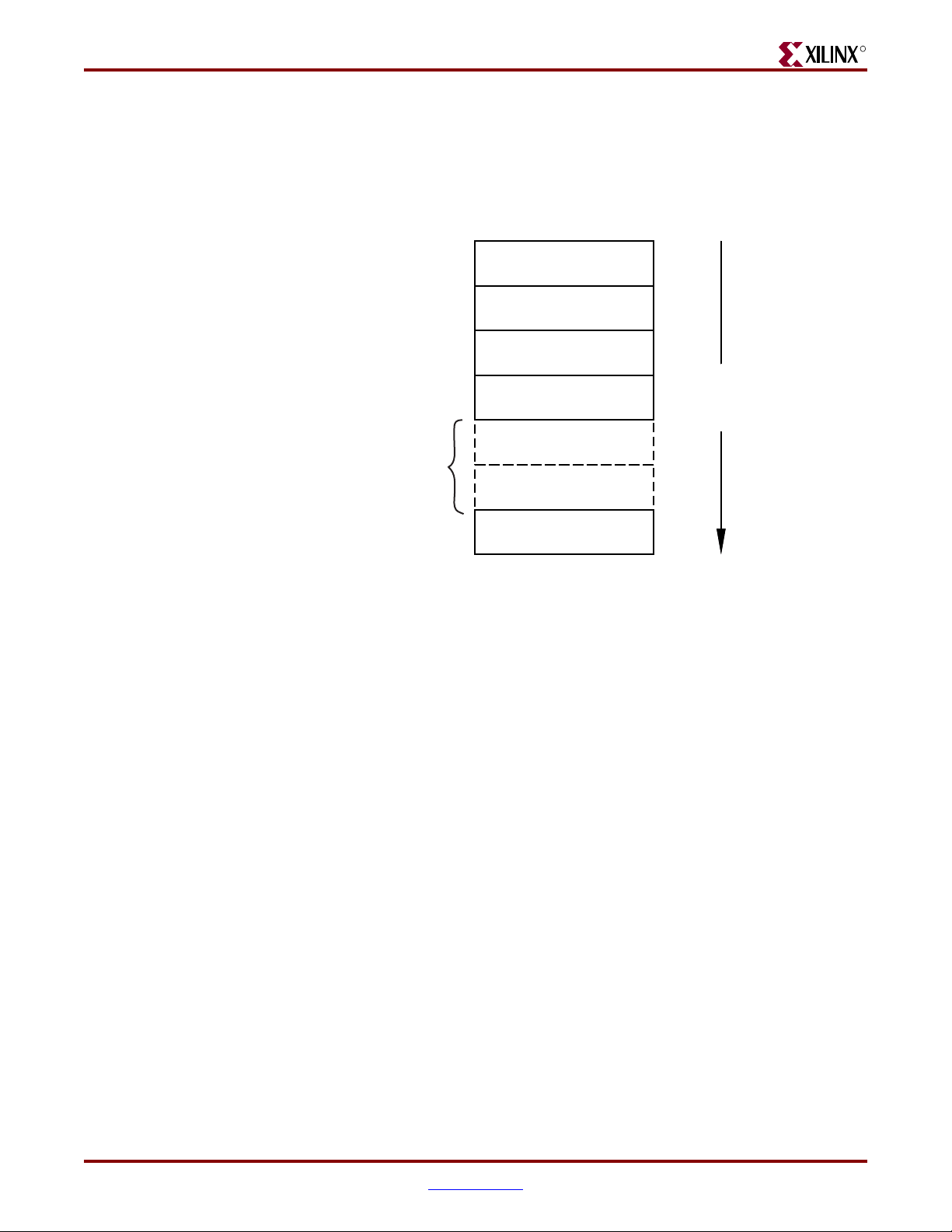
Overview of Flow Control
Pause Control Frames
Control frames are a unique type of Ethernet frame, defined in clause 31 of the IEEE 802.32005 standard. Control frames are differentiated from other frame types by a defined value
placed in the length/type field (MAC Control Type code). Figure 6-2 illustrates the control
frame format.
-- DISCONTINUED PRODUCT --
R
6 OCTETS
6 OCTETS
2 OCTETS
2 OCTETS
44 OCTETS
4 OCTETS
DESTINATION
ADDRESS
SOURCE
ADDRESS
LENGTH/TYPE
MAC CONTROL
OPCODE
MAC CONTROL
PARAMETERS
RESERVED
(transmitted as zeroes)
FRAME CHECK
SEQUENCE
Figure 6-2: MAC Control Frame Format
FRAME
TRANSMITTED
TOP-TO-BOTTOM
A pause control frame is a unique type of control frame, identified by a defined value
placed in the MAC Control opcode field.
Note:
for Ethernet Passive Optical Networks.
MAC Control opcodes other than for pause (flow control) frames have recently been defined
The MAC control parameter field of the pause control frame contains a 16-bit field
containing a binary value directly related to the pause duration. This defines the number of
pause_quantum (512 bit times of the particular implementation). For 1-Gigabit Ethernet,
a single pause_quantum corresponds to 512 ns.
1-Gigabit Ethernet MAC v8.5 User Guide www.xilinx.com 55
UG144 April 24, 2009
Page 56

-- DISCONTINUED PRODUCT --
R
Flow Control Operation of the GEMAC
Transmitting a PAUSE Control Frame
Core-initiated Pause Request
If the GEMAC core is configured to support transmit flow control, the client can initiate a
pause control frame by asserting pause_req (see “Flow Control Configuration,” on page
81). Figure 6-3 illustrates pause request timing.
gtx_clk
pause_req
pause_val[15:0]
Chapter 6: Using Flow Control
Figure 6-3: Pause Request Timing
This action causes the core to construct and transmit a pause control frame on the link with
the following MAC Control frame parameters (Figure 6-2):
• The destination address used is an IEEE802.3 globally assigned multicast address (to
which any flow control-capable MAC will respond).
• The source address used is the configurable pause frame MAC address (see“Receiver
Configuration,” on page 79).
• The value sampled from the pause_val[15:0] port at the time of the pause_req
assertion will be encoded into the MAC control parameter field to select the duration
of the pause (in units of pause_quantum).
If the transmitter is inactive at the time of the pause request, this pause control frame is
transmitted immediately. If the transmitter is currently busy, the current frame being
transmitted is allowed to complete, followed by the pause control frame (in preference to
any pending client-supplied frame).
A pause control frame initiated by this method is transmitted even if the transmitter has
ceased in response to receiving an inbound pause request.
Note:
asserted numerous times in a short time period (before the control pause frame transmission has
begun), only a single pause control frame is transmitted. The most recent value sampled will be the
pause_val[15:0] value used.
Only a single pause control frame request is stored by the transmitter. if pause_req is
Client Initiated Pause Request
For maximum flexibility, flow control logic can be disabled in the core and alternatively
implemented in the client logic connected to the core (see “Flow Control Configuration,”
on page 81). Any type of control frame can be transmitted through the core through the
client interface using the same transmission procedure as a standard Ethernet frame (see
“Transmitting Outbound Frames,” on page 47).
56 www.xilinx.com 1-Gigabit Ethernet MAC v8.5 User Guide
UG144 April 24, 2009
Page 57

Flow Control Operation of the GEMAC
Receiving a Pause Control Frame
Core Initiated Response to a Pause Request
An error free control frame is a received frame matching the format of Figure 6-2. It must
pass all standard receiver frame checks (for example, FCS field checking). In addition, the
control frame received must be exactly 64-bytes in length (from destination address
through to the FCS field inclusive: this is minimum legal Ethernet MAC frame size and the
defined size for control frames).
Any control frame received that does not conform to these checks contains an error and is
passed to the receiver client with the rx_bad_frame signal asserted.
Pause Frame Reception Disabled
When pause control reception is disabled, an error free control frame is received through
the client interface with rx_good_frame asserted (see “Flow Control Configuration,” on
page 81). In this way, the frame is passed to the client logic for interpretation (see “Client
Initiated Response to a Pause Request,” on page 57).
-- DISCONTINUED PRODUCT --
R
Pause Frame Reception Enabled
When pause control reception is enabled, and an error-free frame is received by the
GEMAC core (see “Flow Control Configuration,” on page 81), the following frame
decoding functions are performed:
• The destination address field is matched against the IEEE 802.3 globally assigned
multicast address or the configurable pause frame MAC address (see “Configuration
Registers,” on page 78).
• The length/type field is matched against the MAC control type code.
• The opcode field contents are matched against the Pause opcode.
If any of the previously described checks are false, the frame is ignored by the Flow Control
logic and passed up to the client logic for interpretation by marking it with
rx_good_frame asserted. It is then the responsibility of the MAC client logic to decode,
act on (if required), and drop this control frame.
If all the previously described checks are true, the 16-bit binary value in the MAC Control
Parameters field of the control frame is then used to inhibit transmitter operation for the
required number of pause_quantum. This inhibit is implemented by delaying the assertion
of tx_ack at the transmitter client interface until the requested pause duration has
expired. The received pause frame is then passed on to the client with rx_bad_frame
asserted to indicate to the client that the pause frame can be dropped.
Note:
the receiver client logic. All control frames are indicated by rx_statistic_vector bit 19 (see
“Receiver Statistics Vector,” on page 44).
Any frame in which the length/type field contains the MAC control type should be dropped by
Client Initiated Response to a Pause Request
For maximum flexibility, flow control logic can be disabled in the core and alternatively
implemented in the client logic connected to the core (see “Flow Control Configuration,”
on page 81). Any type of error-free control frame is then passed through the core with
rx_good_frame asserted. The frame is passed to the client for interpretation. It is then the
responsibility of the client to drop this control frame and to act on it by ceasing
transmission through the core, if applicable.
1-Gigabit Ethernet MAC v8.5 User Guide www.xilinx.com 57
UG144 April 24, 2009
Page 58

-- DISCONTINUED PRODUCT --
R
Flow Control Implementation Example
This section provides a basic overview of a Flow Control implementation, using Figure 6-1
as a sample. To summarize the example, the user MAC on the left hand side of the figure
cannot match the full line rate of the link partner MAC on the right hand side due to clock
tolerances. Over time, the FIFO illustrated will fill and overflow. The goal is to implement
a flow control method which will (over a long time period) reduce the average line rate of
the link partner MAC to that of the user MAC.
Method
1. Choose a FIFO nearly full to occupancy threshold (7/8 occupancy is used in this
description—but the choice of threshold is implementation specific). When the
occupancy of the FIFO exceeds this occupancy, initiate a single pause control frame,
from the user MAC, with 0xFFFF used as the pause_quantum duration (0xFFFF is
placed on pause_val[15:0]). This is the maximum pause duration. This causes the
link partner MAC to cease transmission, and the FIFO of the user system will start to
empty.
2. Choose a second FIFO occupancy threshold (3/4 is used in this description—but the
choice of threshold is implementation specific). When the occupancy of the FIFO falls
below this occupancy, initiate a second pause control frame from the user MAC, with
0x0000 used as the pause_quantum duration (0x0000 is placed on pause_val[15:0]).
This indicates a zero pause duration, and upon receiving this pause control frame, the
link partner MAC immediately resumes transmission (it does not wait for the original
requested pause duration to expire). This pause control frame can therefore be
considered a “pause cancel” command.
Chapter 6: Using Flow Control
58 www.xilinx.com 1-Gigabit Ethernet MAC v8.5 User Guide
UG144 April 24, 2009
Page 59
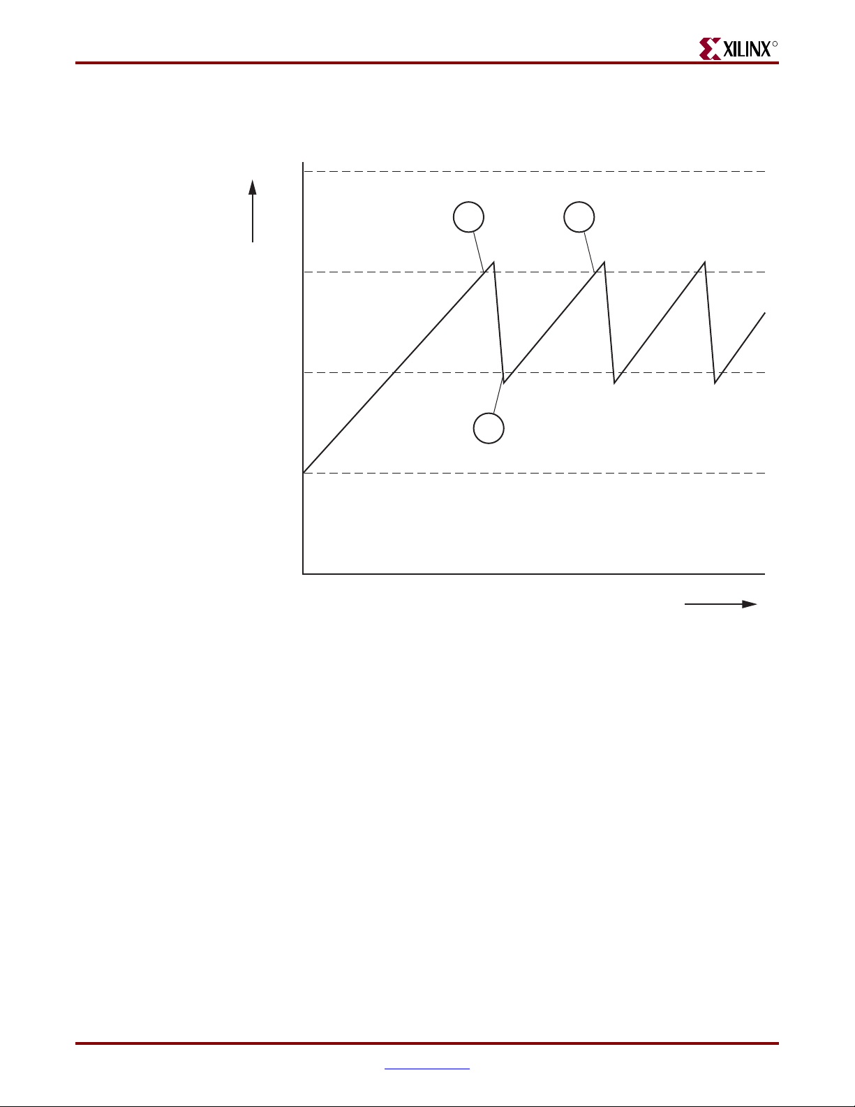
-- DISCONTINUED PRODUCT --
Flow Control Implementation Example
Operation
Figure 6-4 illustrates the FIFO occupancy over a period of time.
Full
R
A
C
7/8
FIFO occupancy
3/4
B
5/8
1/2
time
Figure 6-4: Flow Control Implementation Triggered from FIFO Occupancy
The following describes the sequence of flow control operation.
1. The average FIFO occupancy of the user system gradually increases over time due to
the clock tolerances. At point A, the occupancy has reached the threshold of 7/8
occupancy. This triggers the maximum duration pause control frame request.
2. On receiving the pause control frame, the link partner MAC ceases transmission.
3. After the link partner MAC ceases transmission, the occupancy of the FIFO in the user
system rapidly empties. The occupancy falls to the second threshold of 3/4 occupancy
at point B. This triggers the zero duration pause control frame request (the pause
cancel command).
4. On receiving this second pause control frame, the link partner MAC resumes
transmission.
5. Normal operation resumes and the FIFO occupancy again gradually increases over
time. At point C, this Flow Control cycle repeats.
1-Gigabit Ethernet MAC v8.5 User Guide www.xilinx.com 59
UG144 April 24, 2009
Page 60

-- DISCONTINUED PRODUCT --
R
Chapter 6: Using Flow Control
60 www.xilinx.com 1-Gigabit Ethernet MAC v8.5 User Guide
UG144 April 24, 2009
Page 61

-- DISCONTINUED PRODUCT --
R
Using the Physical Side Interface
This chapter provides general guidelines for creating designs using the Physical Side
Interface of the GEMAC core. The physical side interface implements GMII-style signaling
and is typically attached to a physical layer device (PHY), either off-chip or internally
integrated. See “Physical Side Interface” in Chapter 2. For information about using an
internal interface in conjunction with the Ethernet 1000BASE-X PCS/PMA or SGMII core,
see Chapter 11, “Interfacing to Other Cores.”
The remainder of this chapter describes how to use the core with an external GMII or
RGMII. See also Chapter 9, “Constraining the Core” for a listing of required constraints.
Chapter 7
Implementing External GMII
The HDL example design that is delivered with the core will implement an external GMII
when GMII is selected from the CORE Generator™ GUI (see Chapter 3, “Generating the
Core”). For more information about the example design, see the 1-Gigabit Ethernet MAC
Getting Started Guide.
GMII Transmitter Logic
Figure 7-1 illustrates how to use the physical transmitter interface of the core to create an
external GMII in a Spartan®-3 device. The signal names and logic shown in this figure
exactly match those delivered with the example design when the GMII is selected. If other
families are chosen, equivalent primitives and logic specific to that family is used in the
example design.
Figure 7-1 shows that the output transmitter signals are registered in device IOBs before
driving them to the device pads. The logic required to forward the transmitter clock is also
shown. This logic uses an IOB output Double-Data-Rate (DDR) register so that the clock
signal produced incurs exactly the same delay as the data and control signals. This clock
signal, gmii_tx_clk, is inverted with respect to gtx_clk so that the rising edge of
gmii_tx_clk will occur in the centre of the data valid window, therefore maximizing
setup and hold times across the interface.
1-Gigabit Ethernet MAC v8.5 User Guide www.xilinx.com 61
UG144 April 24, 2009
Page 62
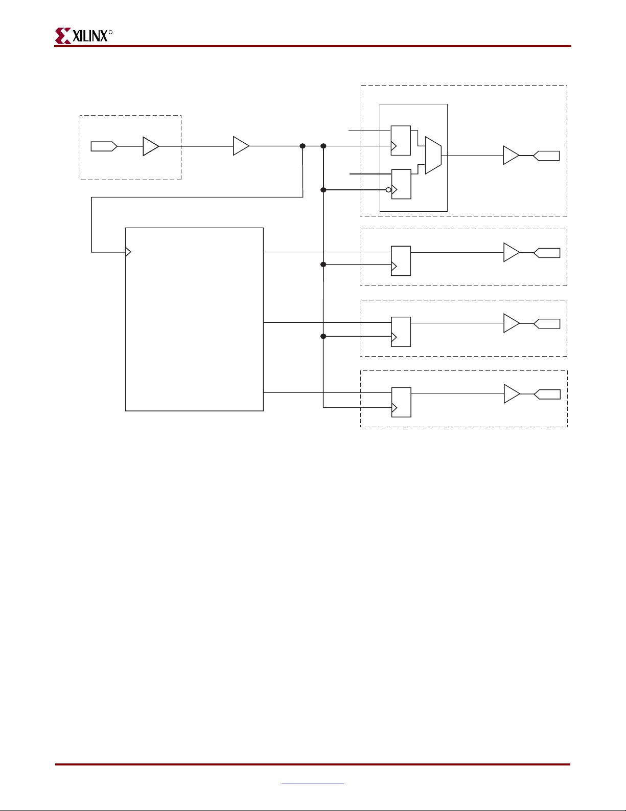
-- DISCONTINUED PRODUCT --
R
Chapter 7: Using the Physical Side Interface
IOB LOGIC
gtx_clk
IPAD
IOB LOGIC
IBUFG
1-Gigabit Ethernet MAC LogiCORE
gtx_clk
BUFG
gmii_txd[0]
gmii_tx_en
gmii_tx_er
gtx_clk_bufg
gmii_txd_int[0]
gmii_tx_en_int
gmii_tx_er_int
FDDRRSE
'0'
'1'
DQ
DQ
DQ
DQ
DQ
gmii_txd_reg[0]
gmii_tx_en_reg
gmii_tx_er_reg
OBUF
OBUF
OBUF
OBUF
gmii_tx_clk
OPAD
gmii_txd[0]
OPAD
gmii_tx_en
OPAD
gmii_tx_er
OPAD
Figure 7-1: External GMII Transmitter Logic
62 www.xilinx.com 1-Gigabit Ethernet MAC v8.5 User Guide
UG144 April 24, 2009
Page 63
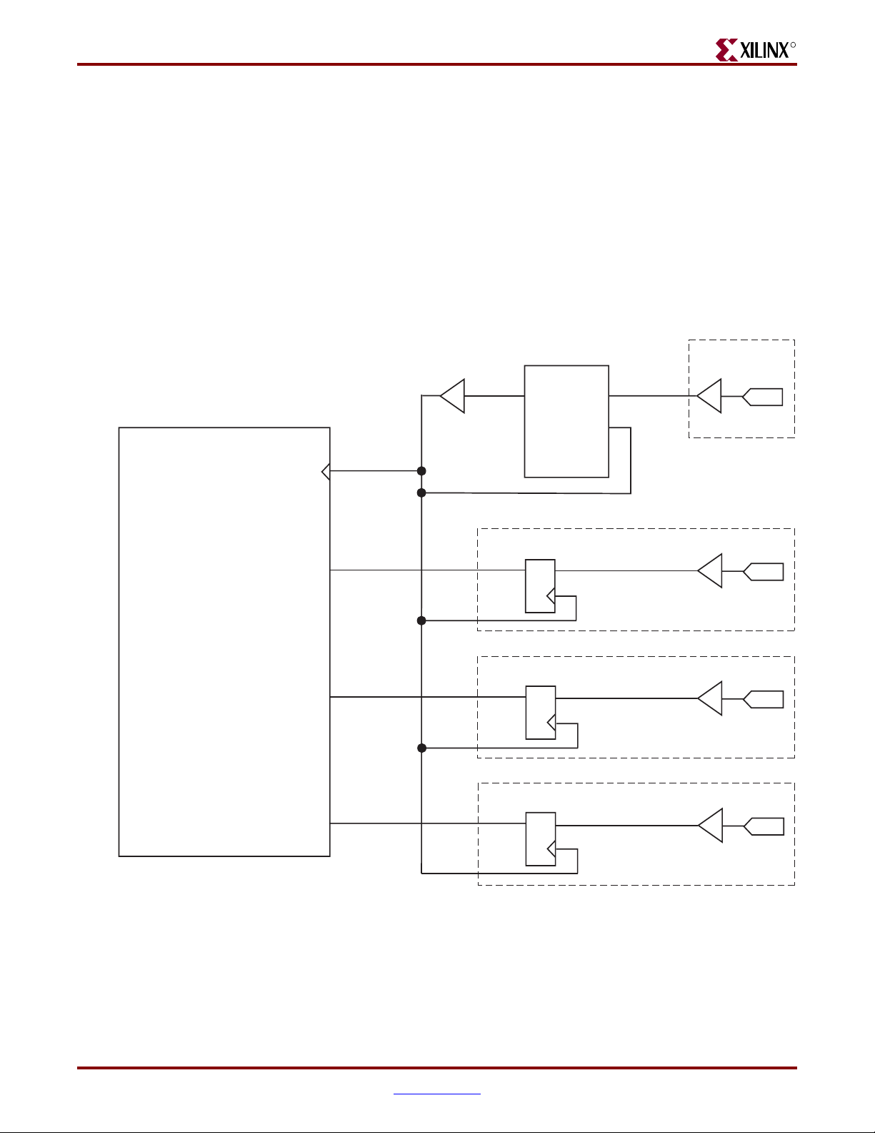
Implementing External GMII
GMII Receiver Logic
Spartan-3, Spartan-3E, Spartan-3A and Virtex-4 Devices
A DCM must be used on the gmii_rx_clk clock path, as illustrated in Figure 7-2, to meet
the input setup and hold requirements for GMII. This is performed by the example designs
delivered with the core (all signal names and logic match Figure 7-2). This DCM circuitry
may optionally be used in other families.
Phase-shifting may then be applied to the DCM to fine-tune the setup and hold times at the
GMII IOB input flip-flops. Fixed phase-shift is applied to the DCM with the example UCF
for the example design. See Appendix C, “Calculating DCM Phase-Shifting.”
-- DISCONTINUED PRODUCT --
R
IOB LOGIC
1-Gigabit Ethernet MAC LogiCORE
gmii_rx_clk
gmii_rxd[0]
gmii_rx_dv
gmii_rxd_reg[0]
gmii_rx_dv_reg
BUFG
gmii_rx_clk0
gmii_rx_clk_bufg
CLK0
Q
Q
DCM
D
D
CLKIN
FB
IOB LOGIC
IBUFG
IBUF
IBUF
gmii_rx_clk
IPAD
gmii_rxd[0]
IPAD
gmii_rx_dv
IPAD
IBUF
gmii_rx_er
gmii_rx_er_reg
Q
D
gmii_rx_er
IPAD
Figure 7-2: External GMII Receiver Logic for Spartan-3, Spartan-3E, and Spartan-3A Devices
1-Gigabit Ethernet MAC v8.5 User Guide www.xilinx.com 63
UG144 April 24, 2009
Page 64

-- DISCONTINUED PRODUCT --
R
Chapter 7: Using the Physical Side Interface
DCM Reset circuitry
A DCM reset module, not illustrated in Figure 7-2, is also present and is instantiated in the
example design next to the DCM. Since this logic must be reliable whatever the
reset/locked status of the DCM, the module requires a reliable reference clock. In the
example design for GMII, the global transmitter clock is therefore used (gtx_clk_bufg
from Figure 7-1). This reset circuitry will generate an appropriate reset pulse, based on the
family, for the receiver DCM under the following conditions:
• The locked signal from the DCM is constantly monitored. Following a high to low
transition on this signal, indicating that the DCM has lost lock, a reset will be issued.
• A timeout counter is enabled when the DCM is in the loss of lock state. If, following
the timeout period, the DCM has not obtained lock, another DCM reset will be issued.
This timeout counter will time a > 1ms interval. This timeout functionality is required
for DCMs connected to Ethernet PHYs since the PHYs may source discontinuous
clocks under certain network conditions (for example, when no ethernet cable is
connected).
Spartan-3 Devices
For Spartan-3 families, the reset pulse is transferred into the DCM input clock
(gmii_rx_clk from Figure 7-2). Here it is extended to three DCM clock periods duration
and routed to the reset input of the DCM.
Virtex-4 Devices
For Virtex®-4 families, the generated reset from within the DCM reset module is further
complicated. Here the DCM reset pulse duration must be asserted for a minimum of 200
ms (see the Virtex-4 Datasheet). Consequently, a 200 ms duration timer is also included in
the DCM reset module to extend the reset pulse. This reset signal is output from the DCM
reset module and should be routed to the DCM reset input port.
Caution!
reset module is NOT connected directly to the DCM: this signal must be connected when
implementing the core in real hardware.
In the example designs for Virtex-4 families, the 200ms reset pulse from the DCM
For Virtex-4 FPGA example designs, the reason why the 200ms input is not routed directly
to the DCM is so that simulations can occur in a timely manner.
The 200ms reset pulse takes the signal name reset_200ms in the example design HDL
files. It is routed from the DCM reset module instantiation up through all levels of
hierarchy to the top level. It is then left unconnected in the example design instantiation
from within the demonstration test bench. Furthermore, an accompanying signal,
reset_200ms_in, is routed down from the top level of the example design hierarchy to
the DCM instantiation, where it is connected to the DCM reset. From the demonstration
test bench, this reset_200ms_in signal is driven for a short duration to enable fast
simulation start up. However, to re-iterate, when implementing the design in real
hardware, the DCM reset signal must be connected correctly:
• This can be achieved by connecting the reset_200ms signal to the
reset_200ms_in signal at any level of example design HDL hierarchy.
64 www.xilinx.com 1-Gigabit Ethernet MAC v8.5 User Guide
UG144 April 24, 2009
Page 65

Implementing External GMII
Virtex-5 Devices
An IODELAY component may be used on the clock, data and control paths, as illustrated
in Figure 7-3. These can be used to either shift the input clock gmii_rx_clk or the data
and control signals to meet the setup and hold requirements of GMII and to allow for any
bus skew across the data and control inputs. The IODELAY components are used in fixed
delay mode, where the attribute IDELAY_VALUE determines the tap delay value. An
IDELAYCTRL primitive must be instantiated for this mode of operation. See the Virte x-5
FPGA User Guide for more information on the use of IDELAYCTRL and IODELAY
components.
-- DISCONTINUED PRODUCT --
R
IOB LOGIC
1-Gigabit Ethernet MAC LogiCORE
gmii_rx_clk
gmii_rxd[0]
gmii_rx_dv
gmii_rx_er
gmii_rxd_reg[0]
gmii_rx_dv_reg
gmii_rx_er_reg
BUFG
IBUFG
IBUF
IBUF
IBUF
gmii_rx_clk
IPAD
gmii_rxd[0]
IPAD
gmii_rx_dv
IPAD
gmii_rx_er
IPAD
IODELAY
Q
D
Q
D
Q
D
IODELAY
IODELAY
IODELAY
Figure 7-3: External GMII Receiver Logic for Virtex-5 Devices
1-Gigabit Ethernet MAC v8.5 User Guide www.xilinx.com 65
UG144 April 24, 2009
Page 66
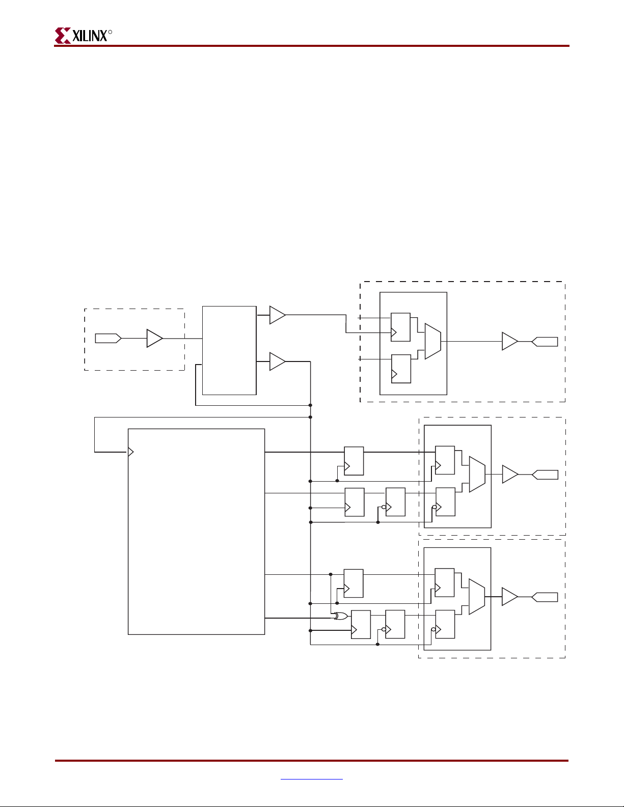
-- DISCONTINUED PRODUCT --
R
Implementing External RGMII
The HDL example design delivered with the core implements an external RGMII when
RGMII is selected from the CORE Generator GUI (see Chapter 3, “Generating the Core”).
For more information about using the example design, see the 1-Gigabit Ethernet MAC
Getting Started Guide.
RGMII Transmitter Logic
Spartan-3, Spartan-3E, Spartan-3A and Spartan-3A DSP Devices
Figure 7-4 illustrates how to use the physical transmitter interface of the core to create an
external RGMII in a Spartan-3 device. The signal names and logic precisely match those
delivered with the example design when the RGMII is selected. If other families are used,
equivalent primitives and logic specific to that family is used in the example design.
BUFG
CLK0
gtx_clk
IPAD
IOB LOGIC
IBUFG
DCM
CLKIN
FB
CLK90
rgmii_tx_clk_bufg
gtx_clk_bufg
Chapter 7: Using the Physical Side Interface
IOB LOGIC
FDDRRSE
'1'
'0'
DQ
DQ
OBUF
rgmii_txc
OPAD
1-Gigabit Ethernet MAC Core
gtx_clk
Figure 7-4: External RGMII Transmitter Logic
gmii_txd[0]
gmii_txd[4]
gmii_tx_en
gmii_tx_er
gmii_txd_int[0]
gmii_txd_int[4]
gmii_tx_en_int
gmii_tx_er_int
DQ
DQ
DQ
DQ
DQ
DQ
IOB LOGIC
FDDRRSE
DQ
DQ
FDDRRSE
DQ
DQ
OBUF
OBUF
rgmii_txd[0]
OPAD
rgmii_tx_ctl
OPAD
66 www.xilinx.com 1-Gigabit Ethernet MAC v8.5 User Guide
UG144 April 24, 2009
Page 67

Implementing External RGMII
Figure 7-4 shows that the output transmitter signals are registered on gtx_clk_bufg, in
the FPGA fabric, including the encoded rgmii_tx_ctl_int signal, derived from the
logical xor of gmii_tx_en_int and gmii_tx_er_int. The signals to be transmitted on
the RGMII falling clock edge are then registered on the falling edge of this clock. This
ensures that the data is presented to the Double Data Rate registers at the correct time.
Finally, the transmitter signals are registered by an IOB output Double-Data-Rate (DDR)
register before being driven to output pads.
The logic required to forward the transmitter clock is also shown. This uses an IOB output
DDR register so the clock signal produced incurs on exactly the same delay as the data and
control signals. The rgmii_tx_clk clock signal is phase-shifted by 90 degrees in the
DCM with respect to gtx_clk_bufg. This means that the rising edge of rgmii_txc
occurs in the center of the data valid window—which maximizes setup and hold times
across the interface, as specified in the Reduced Gigabit Media Independent Interface (RGMII)
Version 2.0 specification.
Virtex-4 Devices
Figure 7-5 shows using the physical transmitter interface of the core to create an external
RGMII in a Virtex-4 device. The signal names and logic shown exactly match those
delivered with the example design when the RGMII is selected
-- DISCONTINUED PRODUCT --
R
Figure 7-5 also shows that the output transmitter signals are registered in the IOBs in
ODDR components. These components convert the input signals into one double-data-rate
signal. These signals are then output through OBUFs before being driven to output pads.
1-Gigabit Ethernet MAC v8.5 User Guide www.xilinx.com 67
UG144 April 24, 2009
Page 68

-- DISCONTINUED PRODUCT --
R
Chapter 7: Using the Physical Side Interface
IOB LOGIC
gtx_clk
IPAD
IOB LOGIC
IBUFG
1-Gigabit Ethernet MAC Core
gtx_clk
DCM
CLKIN
FB
CLK90
CLK0
gmii_txd[0]
gmii_txd[4]
BUFGMUX
rgmii_tx_clk_bufg
gtx_clk_bufg
gmii_txd_int[0]
gmii_txd_int[4]
ODDR
'1'
'0'
D1
D2
C
Q
OBUF
rgmii_txc
OPAD
IOB LOGIC
ODDR
D1
D2
C
Q
OBUF
rgmii_txd[0]
OPAD
IOB LOGIC
ODDR
gmii_tx_en
gmii_tx_er
gmii_tx_en_int
gmii_tx_er_int
D1
D2
C
Q
OBUF
rgmii_tx_ctl
OPAD
Figure 7-5: External RGMII Transmitter Logic in Virtex-4 Devices
The logic required to forward the transmitter clock is also shown: this uses an ODDR
register so that the clock signal produced incurs exactly on the same delay as the data and
control signals. The rgmii_tx_clk clock signal is phase-shifted by 90 degrees in the
DCM with respect to gtx_clk_bufg. This means that the rising edge of rgmii_txc
occurs in the center of the data valid window—which maximizes setup and hold times
across the interface, as specified in the RGMII v2.0 specification.
The use of the BUFGMUX shown, with one input connected to the DCM CLK90 output is
included so that a reliable 125MHz clock source is always provided on global routing
(when the DCM is held in reset, the DCM input clock is instead selected). This is required
to always provided a reliable clock for the receiver logic DCM: see “DCM Reset circuitry”.
68 www.xilinx.com 1-Gigabit Ethernet MAC v8.5 User Guide
UG144 April 24, 2009
Page 69

Implementing External RGMII
Virtex-5 Devices
The same logic that is used in Figure 7-5 can also be used without modification for Virtex-5
devices. However, an alternative solution has been adopted for the example design
delivered with the core. Figure 7-6 shows using the physical transmitter interface of the
core to create an external RGMII in a Virtex-5 device. The signal names and logic shown
exactly match those delivered with the example design when the RGMII is selected.
Figure 7-6 also shows that the output transmitter signals are registered in the IOBs in
ODDR components. These components convert the input signals into one double-data-rate
signal. The ODDR outputs are passed through IODELAYs—and these can be used to
adjust the relationship between the individual signals. These signals are then output
through OBUFs before being driven to output pads.
-- DISCONTINUED PRODUCT --
R
IOB LOGIC
ODDR
gtx_clk
IPAD
IOB LOGIC
gtx_clk
IBUFG
1-Gigabit Ethernet MAC Core
gmii_txd[0]
gmii_txd[4]
gmii_tx_en
gmii_tx_er
gtx_clk_bufg
gmii_txd_int[0]
gmii_txd_int[4]
gmii_tx_en_int
gmii_tx_er_int
‘1’
‘0’
D1
D2
C
IODELAY
Q
OBUF
rgmii_txc
OPAD
IOB LOGIC
ODDR
D1
D2
C
Q
IODELAY
OBUF
rgmii_txd[0]
OPAD
IOB LOGIC
ODDR
D1
D2
Q
IODELAY
OBUF
rgmii_tx_ctl
OPAD
C
Figure 7-6: External RGMII Transmitter Logic in Virtex-5 Devices
1-Gigabit Ethernet MAC v8.5 User Guide www.xilinx.com 69
UG144 April 24, 2009
Page 70

-- DISCONTINUED PRODUCT --
R
The logic required to forward the transmitter clock is also shown. It has matching logic to
the data and control signals to provide a known relationship between the signals. An
IODELAY component is used to phase-shift the rgmii_txc clock signal by 90 degrees
with respect to gtx_clk_bufg. This allows the rising edge of rgmii_txc to occur in the
center of the data valid window—which maximizes setup and hold times across the
interface, as specified in the RGMII v2.0 specification. The IODELAY component is used in
fixed delay mode, where the attribute ODELAY_VALUE determines the tap delay value. An
IDELAYCTRL primitive must be instantiated for this mode of operation. See the Virte x-5
User Guide for more information on the use of IDELAYCTRL and IODELAY components.
RGMII Receiver Logic
Spartan-3, Spartan-3E, Spartan-3A and Spartan-3A DSP Devices
Figure 7-7 shows using the physical receiver interface of the core to create an external
RGMII in a Spartan-3 device. The signal names and logic exactly match those delivered
with the example design when the RGMII is selected. If other families are used, equivalent
primitives and logic specific to that family is used in the example design.
Chapter 7: Using the Physical Side Interface
Figure 7-7 also shows that the input receiver signals are registered in device IOBs on rising
and falling edges of gmii_rx_clk_bufg. The signals are then registered inside the FPGA
fabric, before a final register stage to synchronize signals to the rising edge clock. To
achieve the required setup and hold times across the interface, the DCM uses a phase-shift
to adjust the clock relative to the data. See Appendix C, “Calculating DCM Phase-
Shifting.”
DCM Reset circuitry
A DCM reset module, not illustrated in Figure 7-7, is also present and is instantiated in the
example design next to the DCM. Since this logic must be reliable whatever the
reset/locked status of the DCM, the module requires a reliable reference clock. In the
example design for RGMII, a transmitter clock source is therefore used for this receiver
DCM.
This reset circuitry will generate an appropriate reset pulse for the receiver DCM of
Figure 7-7 under the following conditions:
• The locked signal from the DCM is constantly monitored. Following a high to low
transition on this signal, indicating that the DCM has lost lock, a reset will be issued.
• A timeout counter is enabled when the DCM is in the loss of lock state. If, following
the timeout period, the DCM has not obtained lock, another DCM reset will be issued.
This timeout counter will time a > 1ms interval. This timeout functionality is required
for DCMs connected to Ethernet PHYs since the PHYs may source discontinuous
clocks under certain network conditions (for example, when no ethernet cable is
connected).
For Spartan-3 families, the reset pulse is transferred into the DCM input clock (rgmii_rxc
from Figure 7-7). Here it is extended to three DCM clock periods duration and routed to
the reset input of the DCM.
70 www.xilinx.com 1-Gigabit Ethernet MAC v8.5 User Guide
UG144 April 24, 2009
Page 71

Implementing External RGMII
-- DISCONTINUED PRODUCT --
R
IOB LOGIC
1-Gigabit Ethernet MAC Core
gmii_rx_clk
gmii_rxd[0]
gmii_rxd[4]
gmii_rx_dv
gmii_rx_clk_bufg
gmii_rxd_reg[0]
gmii_rxd_reg[4]
gmii_rx_dv_reg
BUFG
IBUFG
rgmii_rxc
IPAD
CLK0
DCM
CLKIN
FB
IOB LOGIC
IBUF
IBUF
rgmii_rxd[0]
IPAD
rgmii_rx_ctl
IPAD
D
D
D
rgmii_rxd_ddr[0]
Q
D
rgmii_rxd_ddr[4]
Q
D
rgmii_rx_dv_ddr
Q
D
rgmii_rxd_reg[0]
Q
D
DQ
Q
D
Q
rgmii_rxd_reg[4]
Q
rgmii_rx_dv_reg
Q
rgmii_rx_ctl_reg
Q
gmii_rx_er
gmii_rx_er_reg
DQ
Figure 7-7: External RGMII Receiver Logic
D
rgmii_rx_ctl_ddr
Q
D
1-Gigabit Ethernet MAC v8.5 User Guide www.xilinx.com 71
UG144 April 24, 2009
Page 72

R
Virtex-4 Devices
-- DISCONTINUED PRODUCT --
Chapter 7: Using the Physical Side Interface
Figure 7-8 shows using the physical receiver interface of the core to create an external
RGMII in a Virtex-4 device. The signal names and logic exactly match those delivered with
the example design when RGMII is selected.
Figure 7-8 also shows that the input receiver signals are registered in the IOBs in IDDR
components. These components convert the input double data rate signals into GMII
specification signals. The gmii_rx_er_int signal is derived in the FPGA fabric from
the outputs of the control IDDR component.
To achieve the required setup and hold times across the interface, the DCM uses a phaseshift to adjust the clock relative to the data. See Appendix C, “Calculating DCM Phase-
Shifting.”
DCM Reset circuitry
A DCM reset module, not illustrated in Figure 7-8, is also present and is instantiated in the
example design next to the DCM. Since this logic must be reliable whatever the
reset/locked status of the DCM, the module requires a reliable reference clock. In the
example design for RGMII, a transmitter clock source is therefore used for this receiver
DCM. This is obtained from the BUFGMUX output which is connected to the DCM CLK90
output of Figure 7-5. The clock selection for this BUFGMUX will ensure that a 125MHz
clock is always present on this global clock route, even when the RGMII transmitter DCM
of Figure 7-5 is held in reset itself.
This reset circuitry will generate an appropriate reset pulse for the receiver DCM of
Figure 7-8 under the following conditions:
• The locked signal from the DCM is constantly monitored. Following a high to low
transition on this signal, indicating that the DCM has lost lock, a reset will be issued.
• A timeout counter is enabled when the DCM is in the loss of lock state. If, following
the timeout period, the DCM has not obtained lock, another DCM reset will be issued.
This timeout counter will time a > 1ms interval. This timeout functionality is required
for DCMs connected to Ethernet PHYs since the PHYs may source discontinuous
clocks under certain network conditions (for example, when no ethernet cable is
connected).
For Virtex-4 families, the generated reset from within the DCM reset module must be
asserted for a minimum of 200 ms (see the Virtex-4 Datasheet). Consequently, a 200 ms
duration timer is also included in the DCM reset module to extend the reset pulse. This
reset signal is output from the DCM reset module and should be routed to the DCM reset
input port.
Caution!
reset module is NOT connected directly to the DCM: this signal must be connected when
implementing the core in real hardware. The reason why the 200ms input is not routed directly to
the DCM is so that simulations can occur in a timely manner.
In the example designs for Virtex-4 families, the 200ms reset pulse from the DCM
The 200ms reset pulse takes the signal name reset_200ms in the example design HDL
files. It is routed from the DCM reset module instantiation up through all levels of
hierarchy to the top level. It is then left unconnected in the example design instantiation
from within the demonstration test bench. Furthermore, an accompanying signal,
reset_200ms_in, is routed down from the top level of the example design hierarchy to
the DCM instantiation, where it is connected to the DCM reset. From the demonstration
test bench, this reset_200ms_in signal is driven for a short duration to enable fast
simulation start up. However, to re-iterate, when implementing the design in real
hardware, the DCM reset signal must be connected correctly:
72 www.xilinx.com 1-Gigabit Ethernet MAC v8.5 User Guide
UG144 April 24, 2009
Page 73

Implementing External RGMII
• This can be achieved by connecting the reset_200ms signal to the
reset_200ms_in signal at any level of example design HDL hierarchy.
-- DISCONTINUED PRODUCT --
R
IOB LOGIC
1-Gigabit Ethernet MAC Core
gmii_rx_clk
gmii_rxd[0]
gmii_rxd[4]
gmii_rx_dv
gmii_rx_er
gmii_rx_clk_bufg
gmii_rxd_int[0]
gmii_rxd_int[4]
gmii_rx_dv_int
gmii_rx_er_int
BUFG
Q1
Q2
Q1
Q2
C
CLK0
IDDR
IDDR
DCM
CLKIN
FB
IOB LOGIC
D
IOB LOGIC
D
IBUF
IBUF
IBUFG
rgmii_rxc
IPAD
rgmii_rxd[0]
IPAD
rgmii_rx_ctl
IPAD
C
Figure 7-8: External RGMII Receiver Logic for Virtex-4 Devices
1-Gigabit Ethernet MAC v8.5 User Guide www.xilinx.com 73
UG144 April 24, 2009
Page 74
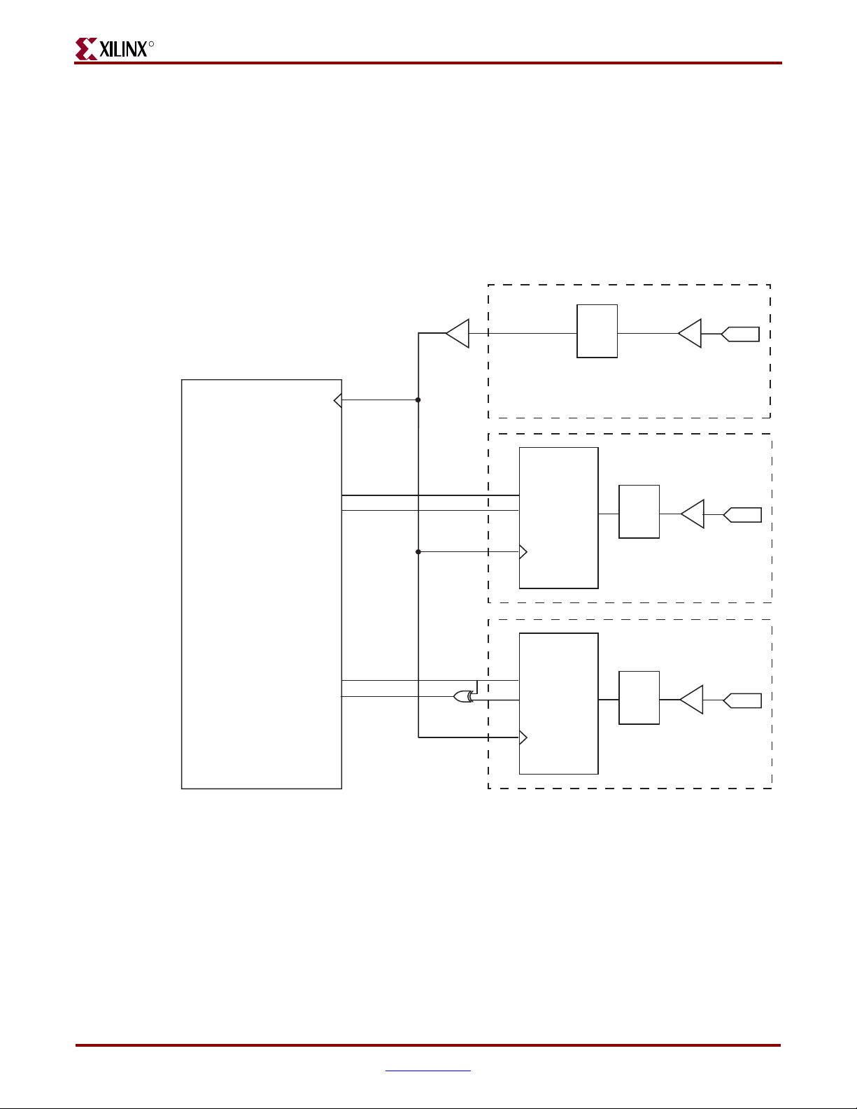
R
Virtex-5 Devices
-- DISCONTINUED PRODUCT --
Chapter 7: Using the Physical Side Interface
Figure 7-9 shows using the physical receiver interface of the core to create an external
RGMII in a Virtex-5 device. The signal names and logic exactly match those delivered with
the example design when RGMII is selected.
Figure 7-9 also shows that the input receiver signals are registered in the IOBs in IDDR
components. These components convert the input double data rate signals into GMII
specification signals. The gmii_rx_er_int signal is derived in the FPGA fabric from the
outputs of the control IDDR component.
IOB LOGIC
1-Gigabit Ethernet MAC Core
gmii_rx_clk
gmii_rxd[0]
gmii_rxd[4]
gmii_rx_dv
gmii_rx_er
gmii_rx_clk_bufg
gmii_rxd_int[0]
gmii_rxd_int[4]
gmii_rx_dv_int
gmii_rx_er_int
BUFG
IODELAY
IBUFG
rgmii_rxc
IPAD
IOB LOGIC
IDDR
Q1
Q2
C
IODELAY
D
IBUF
rgmii_rxd[0]
IPAD
IOB LOGIC
IDDR
Q1
Q2
IODELAY
D
IBUF
rgmii_rx_ctl
IPAD
C
Figure 7-9: External RGMII Receiver Logic for Virtex-5 Devices
The IODELAY components are used to phase-shift the input RGMII clock, data and control
signals to meet the setup and hold margins. The IODELAY components are used in fixed
delay mode, where the attribute IDELAY_VALUE determines the tap delay value. An
IDELAYCTRL primitive must be instantiated for this mode of operation. See the Virte x-5
User Guide for more information on the use of IDELAYCTRL and IODELAY components.
74 www.xilinx.com 1-Gigabit Ethernet MAC v8.5 User Guide
UG144 April 24, 2009
Page 75
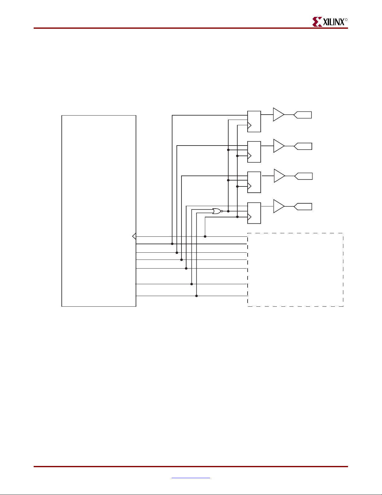
Implementing External RGMII
RGMII Inband Status Decoding Logic
The inband status decoding logic is common to all device families. Figure 7-10 illustrates
the decoding of RGMII inband status information. This information is received through
the RGMII interface between frames. The signal names and logic shown exactly match
those delivered with the example design when the RGMII is selected.
-- DISCONTINUED PRODUCT --
R
1-Gigabit Ethernet MAC Core
gmii_rx_clk
gmii_rxd[0]
gmii_rxd[1]
gmii_rxd[2]
gmii_rxd[3]
gmii_rx_dv
gmii_rx_er
gmii_rx_clk_bufg
gmii_rxd_reg[0]
gmii_rxd_reg[1]
gmii_rxd_reg[2]
gmii_rxd_reg[3]
gmii_rx_dv_reg
gmii_rx_er_reg
OBUF
DQ
CE
OBUF
DQ
CE
OBUF
DQ
CE
OBUF
DQ
CE
RGMII RECEIVER LOGIC
inband_link_status
OPAD
inband_clock_speed[0]
OPAD
inband_clock_speed[1]
OPAD
inband_duplex_status
OPAD
Figure 7-10: RGMII Inband Status Decoding Logic
1-Gigabit Ethernet MAC v8.5 User Guide www.xilinx.com 75
UG144 April 24, 2009
Page 76

-- DISCONTINUED PRODUCT --
R
Using the MDIO interface
The MDIO interface is accessed through the optional management interface and is
typically connected to the MDIO port of a physical-layer device to access its configuration
and status registers (see “MDIO Interface,” on page 86). The MDIO format is defined in
IEEE 802.3, clause 22.
Connecting the MDIO to an Internally Integrated PHY
The MDIO ports of the GEMAC core can be connected to the MDIO ports of an internally
integrated physical-layer device, such as the MDIO port of the Xilinx Ethernet 1000BASEX PCS/PMA or SGMII core. See Chapter 11, “Interfacing to Other Cores” for more
information.
Connecting the MDIO to an External PHY
The MDIO ports of the GEMAC core can be connected to the MDIO of an external
physical-layer device. In this situation, mdio_in, mdio_out, and mdio_tri must be
connected to a tri-state buffer to create a bidirectional wire, mdio. This tri-state buffer can
be either external to the FPGA, or internally integrated by using an IOB IOBUF component
with an appropriate SelectIO
Chapter 7: Using the Physical Side Interface
TM
standard for the external PHY (illustrated in Figure 7-11).
1-Gigabit Ethernet MAC Core
mdc
mdio_tri
mdio_out
mdio_in
Figure 7-11: Creating an External MDIO Interface
IOB LOGIC
OBUF
OI
IOB LOGIC
IOBUF
T
I
O
IO
OPAD
IOPAD
MDC
MDIO
76 www.xilinx.com 1-Gigabit Ethernet MAC v8.5 User Guide
UG144 April 24, 2009
Page 77

-- DISCONTINUED PRODUCT --
R
Configuration and Status
This chapter provides general guidelines for configuring and monitoring the GEMAC
core, including a detailed description of the client-side management interface and registers
present in the core. It also describes the alternative to the optional management interface
which is the Configuration Vector.
Using the Optional Management Interface
The Management Interface is a processor-independent interface with standard address,
data, and control signals. It may be used as is, or a wrapper (not supplied) may be used to
interface to common bus architectures. For port definition, see “Management Interface
(Optional),” on page 28.
Chapter 8
This interface is used for:
• Configuring of the GEMAC core via the configuration registers.
• Access through the MDIO interface to the management registers located in the PHY
connected to the GEMAC core.
The Management Interface can be accessed in different ways, depending on the type of
transaction. A truth table showing which access method is required for each transaction
type is shown in Tab le 8- 1. These access methods are described in the following sections.
Table 8-1: Management Interface Transaction Types
Transaction host_miim_sel host_addr[9]
Configuration 0 1
MIIM access 1 X
Host Clock Frequency
The Management Interface clock, host_clk, is used to derive the MDIO clock, mdc, and
for this reason is subject to the following frequency restriction:
≥
10 MHz
Configuring the GEMAC core to derive the mdc signal from this clock is detailed in “MDIO
Interface,” on page 86.
1-Gigabit Ethernet MAC v8.5 User Guide www.xilinx.com 77
UG144 April 24, 2009
Page 78

-- DISCONTINUED PRODUCT --
R
Configuration Registers
After a power-up or system reset, the client may reconfigure the core parameters using
their defaults. Configuration changes can be written at any time. Both the receiver and
transmitter logic responds only to configuration changes during inter-frame gaps. The
exceptions to this are the configurable resets that take effect immediately.
Configuration of the GEMAC core is performed through a register bank that is accessed
through the management interface. The configuration registers available in the core are
listed in Ta bl e 8- 2 . As shown, the address has some implicit don’t care bits; any access to an
address in the ranges shown performs a 32-bit read or write from the same configuration
word.
Table 8-2: Configuration Registers
Address Description
0x200-0x23F Receiver Configuration (Word 0)
0x240-0x27F Receiver Configuration (Word 1)
0x280-0x2BF Transmitter Configuration
Chapter 8: Configuration and Status
0x2C0-0x2FF Flow Control Configuration
0x300-0x33F Reserved
0x340-0x37F Management Configuration
0x380-0x383 Unicast Address (Word 0) (if Address Filter is present)
0x384-0x387 Unicast Address (Word 1) (if Address Filter is present)
0x388-0x38B Address Table Configuration (Word 0) (if Address Filter is
present)
0x38C-0x38F Address Table Configuration (Word 1) (if Address Filter is
present)
0x390-0x393 Address Filter Mode (if Address Filter is present)
78 www.xilinx.com 1-Gigabit Ethernet MAC v8.5 User Guide
UG144 April 24, 2009
Page 79
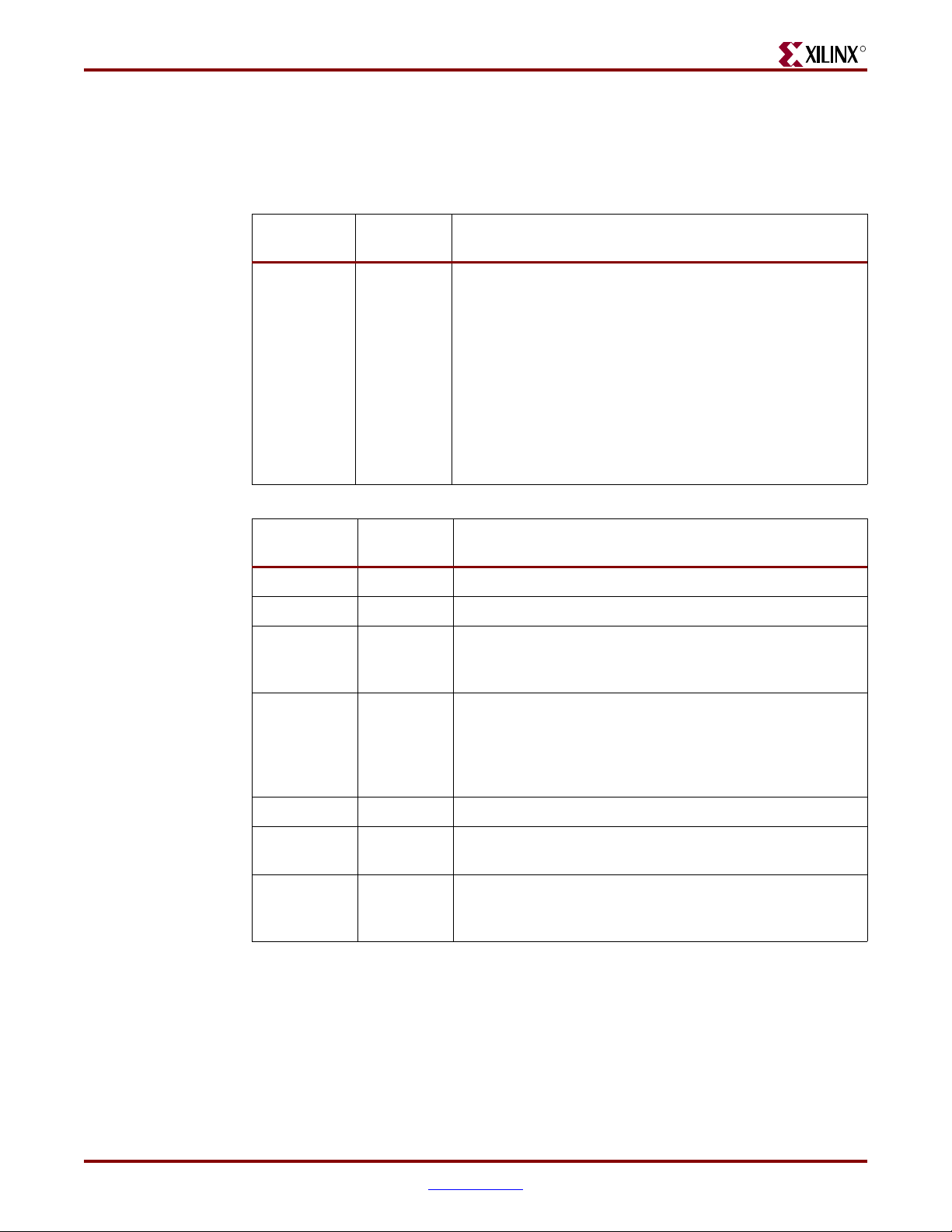
-- DISCONTINUED PRODUCT --
Using the Optional Management Interface
Receiver Configuration
The register contents for the two receiver configuration words are shown in Tab le 8 -3 and
Tab le 8- 4.
Table 8-3: Receiver Configuration Word 0
R
Bit
Default
Val ue
Description
31-0 All 0s Pause frame MAC Source Address[31:0]. This address is
used by the MAC to match against the destination address
of any incoming flow control frames. It is also used by the
flow control block as the source address (SA) for any
outbound flow control frames. See Chapter 6, “Using Flow
Control.”
The address is ordered so the first byte
transmitted/received is the lowest positioned byte in the
register; for example, a MAC address of AA-BB-CC-DDEE-FF would be stored in Address[47:0] as
0xFFEEDDCCBBAA.
Table 8-4: Receiver Configuration Word 1
Bit
Default
Val ue
Description
15-0 All 0s Pause frame MAC Source Address[47:32]
23-16 n/a Reserved
24 0 Control Frame Length Check Disable When this bit is set
to ‘1,’ the core will not mark control frames as ‘bad’ if they
are greater than the minimum frame length.
25 0 Length/Type Error Check Disable When this bit is set to
‘1,’ the core will not perform the length/type field error
checks as described in “Length/Type Field Error Checks,”
on page 43. When this bit is set to ‘0,’ the length/type field
checks will be performed; this is normal operation.
26 n/a Reserved
27 0 VLAN Enable When this bit is set to ‘1,’ VLAN tagged
frames will be accepted by the receiver.
28 1 Receiver Enable. If set to ‘1,’ the receiver block will be
operational. If set to ‘0,’ the block will ignore activity on the
physical interface RX port.
1-Gigabit Ethernet MAC v8.5 User Guide www.xilinx.com 79
UG144 April 24, 2009
Page 80

-- DISCONTINUED PRODUCT --
R
Chapter 8: Configuration and Status
Table 8-4: Receiver Configuration Word 1 (Continued)
Bit
Default
Val ue
Description
29 0 In-band FCS Enable When this bit is ‘1,’ the MAC receiver
will pass the FCS field up to the client. When at ‘0,’ the
client will not be passed the FCS. In both cases, the FCS
will be verified on the frame.
30 0 Jumbo Frame Enable When this bit is set to ‘1,’ the MAC
receiver will accept frames over the specified IEEE 802.3-
2005 maximum legal length. When this bit is ‘0,’ the MAC
will only accept frames up to the specified maximum.
31 0 Reset When this bit is set to ‘1,’ the receiver will be reset.
The bit will then automatically revert to ‘0.’ This reset also
sets all of the receiver configuration registers to their
default values.
Transmitter Configuration
The register contents for the Transmitter Configuration Word are described in Tab le 8- 5.
Table 8-5: Transmitter Configuration Word
Bit
Default
Val ue
Description
24-0 n/a Reserved
25 0 Interframe Gap Adjust Enable If ‘1,’ the transmitter will
read the value on the port tx_ifg_delay at the start of frame
transmission and adjust the interframe gap following the
frame accordingly.
26 n/a Reserved
27 0 VLAN Enable When this bit is set to ‘1,’ the transmitter
will allow the transmission of VLAN tagged frames.
28 1 Transmit Enable When this bit is ‘1,’ the transmitter is
operational. When it is ‘0,’ the transmitter is disabled.
80 www.xilinx.com 1-Gigabit Ethernet MAC v8.5 User Guide
UG144 April 24, 2009
Page 81
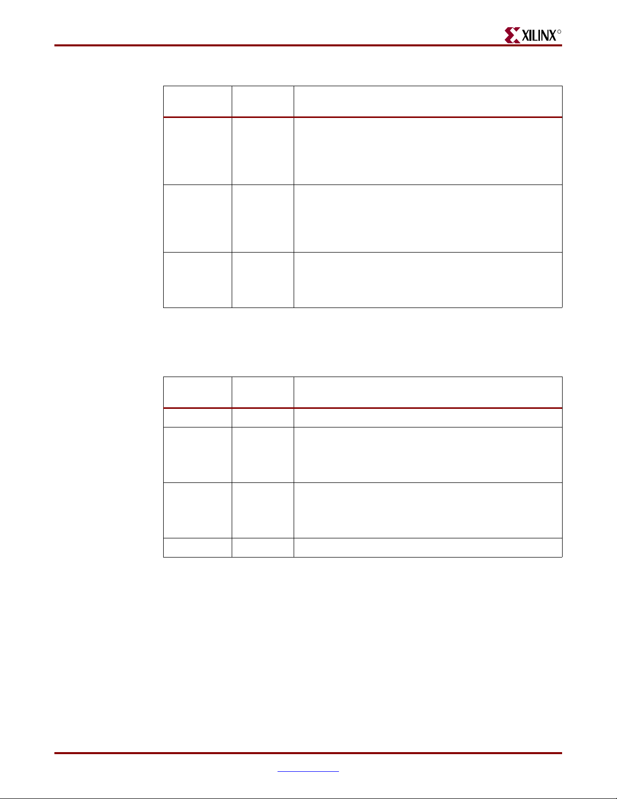
-- DISCONTINUED PRODUCT --
Using the Optional Management Interface
Table 8-5: Transmitter Configuration Word (Continued)
R
Bit
Default
Val ue
Description
29 0 In-band FCS Enable When this bit is ‘1,’ the MAC
transmitter will expect the FCS field to be passed in by the
client. When this bit is ‘0,’ the MAC transmitter will
append padding as required, compute the FCS and
append it to the frame.
30 0 Jumbo Frame Enable When this bit is set to ‘1,’ the MAC
transmitter will send frames that are greater than the
specified IEEE 802.3-2005 maximum legal length. When
this bit is ‘0,’ the MAC will only send frames up to the
specified maximum.
31 0 Reset When set to ‘1,’ the transmitter will be reset. The bit
will then automatically revert to ‘0.’ This reset will also set
all of the transmitter configuration registers to their default
values.
Flow Control Configuration
Tab le 8- 6 lists the register contents for the Flow Control Configuration Word.
Table 8-6: Flow Control Configuration Word
Bit
Default
Val ue
Description
28-0 n/a Reserved
29 1 Flow Control Enable (RX) When this bit is ‘1,’ received
flow control frames will inhibit the transmitter operation.
When this bit is ‘0,’ received flow control frames will
always be passed up to the client.
30 1 Flow Control Enable (TX) When this bit is ‘1,’ asserting the
PAUSE_REQ signal will send a flow control frame out
from the transmitter. When this bit is ‘0,’ asserting the
PAUSE_REQ signal has no effect.
31 n/a Reserved
1-Gigabit Ethernet MAC v8.5 User Guide www.xilinx.com 81
UG144 April 24, 2009
Page 82

R
MDIO Configuration
The register contents for the Management Configuration Word are described in Tab le 8- 7.
Table 8-7: Management Configuration Word
-- DISCONTINUED PRODUCT --
Chapter 8: Configuration and Status
Bits
Default
Val ue
Description
4-0 All 0s Clock Divide[4:0] This value enters a logical equation
which enables the mdc frequency to be set as a divided
down ratio of the host_clk frequency.
50MDIO Enable When this bit is ‘1,’ the MDIO interface can
be used to access attached PHY devices. When this bit is
‘0,’ the MDIO interface is disabled and the MDIO signals
remain inactive.
31-6 n/a Reserved
Address Filter Configuration
Tab le 8- 8 through Ta bl e 8 -1 2 describe the registers used to access the Address Filter
configuration when the GEMAC core implemented with an Address Filter. The register
contents for the two unicast address registers are found in Ta bl e 8 -8 and Tab le 8 - 9.
Table 8-8: Unicast Address Word 0
Bits
31-0 All 0s Address filter unicast address[31:0].
Default
Val ue
Description
The address is ordered so the first byte received is the
lowest positioned byte in the register; for example, a MAC
address of AA-BB-CC-DD-EE-FF would be stored in
Address[47:0] as 0xFFEEDDCCBBAA.
Table 8-9: Unicast Address Word 1
Bits
Default
Val ue
Description
15-0 All 0s Address filter unicast address[47:32].
31-16 N/A Reserved
82 www.xilinx.com 1-Gigabit Ethernet MAC v8.5 User Guide
UG144 April 24, 2009
Page 83

-- DISCONTINUED PRODUCT --
Using the Optional Management Interface
The Address Filter can be programmed to respond to four separate additional addresses
stored in an address table in the Address Filter. Tab le 8 -10 and Tab le 8 -11 describe how the
contents of the address table are set.
Table 8-10: Address Table Configuration Word 0
R
Bits
Default
Val ue
Description
31–0 All 0s MAC Address[31:0].
The address is ordered so the first byte received is the
lowest positioned byte in the register; for example, a MAC
address of AA-BB-CC-DD-EE-FF would be stored in
Address[47:0] as 0xFFEEDDCCBBAA.
Table 8-11: Address Table Configuration Word 1
Bits
Default
Val ue
Description
15–0 All 0s MAC Address[47:32].
17–16 All 0s The location in the address table that the MAC address is
to be written to or read from. There are up to 4 entries in
the table (Location 0 to 3).
22–18 N/A Reserved
23 0 Read not write This bit is set to ‘1’ to read from the address
table. If it is set to ‘1,’ the contents of the table entry that is
being accessed by the bits 17-16 will be output on the
hostrddata bus in consecutive cycles (least significant
word first). If it is set to ‘0,’ the data on bits 15-0 is written
into the table at the address specified by bits 17-16.
31–24 N/A Reserved
The contents of the Address Filter mode register are described in Ta bl e 8 -1 2.
Table 8-12: Address Filter Mode
Bits
Default
Val ue
Description
30–0 N/A Reserved
31 0 Promiscuous Mode If this bit is set to ‘1,’ the Address Filter
operates in promiscuous mode. All frames are passed to
the receiver client, regardless of the destination address.
Writing and Reading to and from the Configuration Registers
Writing to the configuration registers through the management interface is shown in
Figure 8-1. When accessing the configuration registers (when host_addr[9] = ‘1’ and
host_miim_sel = ‘0’), the upper bit of host_opcode functions as an active low write
enable signal. The lower host_opcode bit is a don’t care bit.
1-Gigabit Ethernet MAC v8.5 User Guide www.xilinx.com 83
UG144 April 24, 2009
Page 84

-- DISCONTINUED PRODUCT --
R
host_clk
host_miim_sel
host_opcode[1]
host_addr[8:0]
host_addr[9]
host_wr_data[31:0]
Chapter 8: Configuration and Status
Figure 8-1: Configuration Register Write Timing
Reading from the configuration register words is similar, but the upper host_opcode bit
should be ‘1,’ as shown in Figure 8-2. In this case, the contents of the register appear on
host_rd_data the host_clk edge after the register address is asserted onto
host_addr.
host_clk
host_miim_sel
host_opcode[1]
host_addr[8:0]
host_addr[9]
host_rd_data[31:0]
Figure 8-2: Configuration Register Read Timing
84 www.xilinx.com 1-Gigabit Ethernet MAC v8.5 User Guide
UG144 April 24, 2009
Page 85

-- DISCONTINUED PRODUCT --
Using the Optional Management Interface
Accessing the Address Table
To write to a specific entry in the address table, you must first write the least significant 32bits of the address into the Address Table Configuration (Word 0) register. You then write
the most significant 16 bits together with the location in the table (bits 17–16) to the
Address Table Configuration (Word1) register with bit 23 (read not write) set to ‘0.’ This is
shown in Figure 8-3. Although it is shown in the figure, there is no requirement for the two
writes to be on adjacent cycles.
R
hostclk
hostmiimsel
hostopcode[1]
hostaddr[8:0]
0x188 0x18C
hostaddr[9]
hostwrdata[31:0]
BIT31 BIT0
ADDR[31:0]
BITS15..0 = ADDR[47:32]
BITS17..16 = LOCATION
BIT23 = 0
Figure 8-3: Address Table Write Timing
As shown in Figure 8-4, you must write to the Address Table Configuration register (Word
1) with the location set to the desired table entry and bit 23 set to ‘1’ to read from the
address table. On the next cycle the least significant word appears on the hostrddata
bus. One cycle afterwards, the most significant 16-bits are output on the lower 16 bits of the
bus.
1-Gigabit Ethernet MAC v8.5 User Guide www.xilinx.com 85
UG144 April 24, 2009
Page 86

-- DISCONTINUED PRODUCT --
R
Chapter 8: Configuration and Status
hostclk
hostmiimsel
hostopcode[1]
MDIO Interface
Introduction to MDIO
The MDIO interface for 1 Gbps operation (and slower speeds) is defined in IEEE 802.3
clause 22. This is a two wire interface consisting of a clock, mdc, and a shared serial data
line, mdio.
hostaddr[8:0]
0x18C
hostaddr[9]
hostwrdata[23]
hostwrdata[17:16]
LOCATION
hostrddata[31:0]
Figure 8-4: Address Table Read Timing
31 : 0 47 : 32
An MDIO bus in a system consists of a single Station Management (STA) master
management entity and a number of MDIO Managed Device (MMD) slave entities.
Figure 8-5 illustrates a typical system. All transactions are initiated by the STA entity. The
GEMAC core implements a STA and can be connected to MMDs (PHY devices) to access
their management registers.
86 www.xilinx.com 1-Gigabit Ethernet MAC v8.5 User Guide
UG144 April 24, 2009
Page 87

-- DISCONTINUED PRODUCT --
Using the Optional Management Interface
STA
MAC 1 MAC 2
mdio
mdc
MMD
MMD
R
MMD
MMD
MMD
MMD
Figure 8-5: Typical MDIO-managed System
There are two different transaction types of MDIO for write and read. They are described
in this section.
Abbreviations Used
The following abbreviations apply for the remainder of this chapter.
• PRE Preamble
• ST Start of frame
• OP Operation code
• PHYAD PHY address
• REGAD Register address
• TA Tur n arou nd
Write Transaction
Figure 8-6 shows a write transaction across the MDIO, as defined by OP=’01.’ The
addressed MMD (PHYAD) device takes the 16-bit word in the data field and writes it to the
register at REGAD.
STA drives MDIO
mdc
mdio
Z1 1 1 0 0 1 P4 P3 P2 P1 P0 R4 R3R2 R1R0 1 0 D15
IDLE IDLE32 bits
PRE
D13
1 ZZZ
D14
ST OP PHYAD REGAD TA 16-bit WRITE DATA
D11
D12
D10D9D8D7D6D5D4D3D2D1D0
Figure 8-6: MDIO Write Transaction
1-Gigabit Ethernet MAC v8.5 User Guide www.xilinx.com 87
UG144 April 24, 2009
Page 88

R
mdc
mdio
IDLE IDLE32 bits
-- DISCONTINUED PRODUCT --
Chapter 8: Configuration and Status
Read Transaction
Figure 8-7 shows a Read transaction; this is defined by OP=”10”. The addressed MMD
(PHYAD) device returns the 16-bit word from the register at REGAD.
STA drives MDIO MMD drives MDIO
D13
1 ZZZ
D14
ST OP PRTAD REGAD TA 16-bit READ DATA
PRE
Figure 8-7: MDIO Read Transaction
For details of the register map of MMD (PHY layer devices) and a detailed description of
the operation of the MDIO Interface itself, see IEEE 802.3-2005.
D11
D12
D10D9D8D7D6D5D4D3D2D1D0
Z1 1 1 0 1 0 P4 P3 P2 P1 P0 R4 R3R2 R1R0 Z 0 D15
Accessing MDIO With GEMAC
More information about MDIO with GEMAC can be found in the following sections of this
guide:
• For the GEMAC port definition of the MDIO, see “MDIO Interface” in Chapter 2
• “Connecting the MDIO to an Internally Integrated PHY,” on page 76
• “Connecting the MDIO to an External PHY,” on page 76
The management interface is also used to access the MDIO interface of the GEMAC core.
The MDIO interface supplies a clock to the connected PHY, mdc. This clock is derived from
the host_clk signal using the value in the Clock Divide[4:0] configuration register.
The frequency of mdc is given by the following equation:
f
f
MDC
--------------------------------------------------------------------=
1 Clock Divide[4:0]+()2×
The frequency of mdc given by this equation should not exceed 2.5 MHz to comply with
the IEEE 802.3-2005 specification for this interface. To prevent mdc from being out of
specification, the Clock Divide[4:0] value powers up at 00000. While this value is in
the register, it is impossible to enable the MDIO interface.
For details of the register map of PHY layer devices and a detailed description of the
operation of the MDIO interface itself, see IEEE 802.3-2005.
HOST_CLK
88 www.xilinx.com 1-Gigabit Ethernet MAC v8.5 User Guide
UG144 April 24, 2009
Page 89
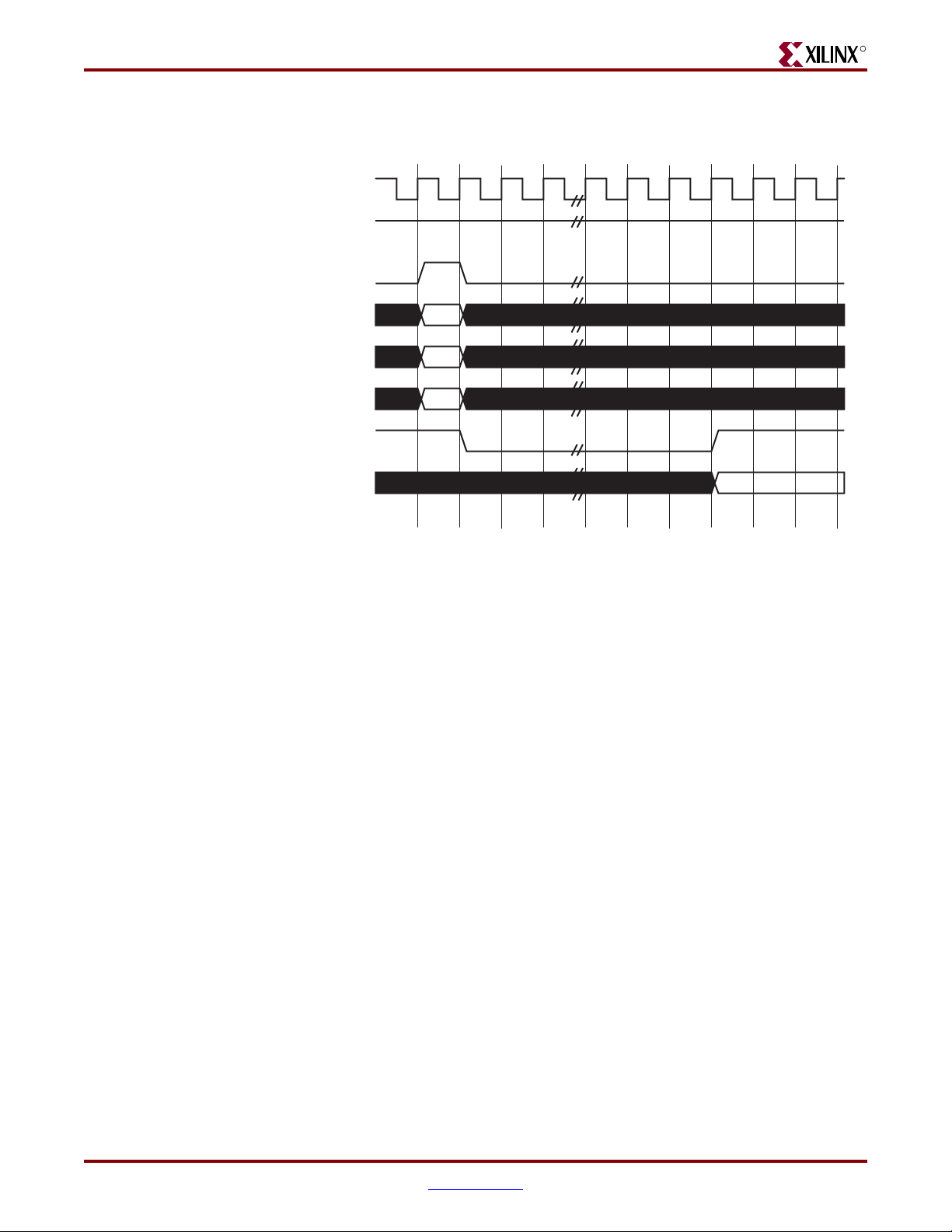
-- DISCONTINUED PRODUCT --
Using the Optional Management Interface
Figure 8-8 shows access to the MDIO interface through the Management Interface.
host_clk
host_miim_sel
host_req
host_opcode1:0]
host_addr9:0]
R
host_wr_data15:0]
host_rdy
host_rd_data[15:0]
* If a read transaction is initiated, the host_rd_data bus is valid
at the point indicated. If a write transaction is initiated, the
host_wr_data bus must be valid at the indicated point.
Simultaneous read and write is not permitted.
*
*
Figure 8-8: MDIO Access through Management Interface
For MDIO transactions, the following applies:
• host_miim_sel is ‘1’
• host_opcode[1:0] maps to the OP (opcode) field of the MDIO frame
• host_addr maps to the two address fields of the MDIO frame; PHYAD is
host_addr[9:5], and REGAD is host_addr[4:0]
• host_wr_data[15:0] maps into the data field of the MDIO frame when
performing a write operation
• The data field of the MDIO frame maps into host_rd_data[15:0] when
performing a read operation
The GEMAC core signals the host that it is ready for an MDIO transaction by asserting
host_miim_rdy. A read or write transaction on the MDIO is initiated by a pulse on the
host_req signal. This pulse is ignored if the MDIO interface already has a transaction in
progress. The GEMAC core then deasserts the host_miim_rdy signal while the
transaction across the MDIO is in progress. When the transaction across the MDIO
interface has been completed, the host_miim_rdy signal is asserted by the GEMAC core;
if the transaction is a read, the data is available on the host_rd_data[15:0] bus at this
time.
1-Gigabit Ethernet MAC v8.5 User Guide www.xilinx.com 89
UG144 April 24, 2009
Page 90

-- DISCONTINUED PRODUCT --
R
Access without the Management Interface
If the optional management interface is omitted from the core, all of the relevant
configuration settings described in Tab le 8 -3 through Tab le 8- 6 are brought out of the core
as signals. These signals are bundled into the configuration_vector[67:0] signal as
described in Tabl e 8 -1 3.
These signals may permanently set by connecting to logic 0 or 1, or may be changed by the
user application at any time; however, with the exception of the reset and the flow control
configuration signals, any changes do not take effect until the current frame has completed
transmission or reception.
The Clock heading in Ta bl e 8 -1 3 denotes which clock domain the configuration signal is
registered into before use by the core. It is not necessary to drive the signal from this clock
domain.
Table 8-13: Configuration Vector Bit Definition
Configuration
Bit(s)
Register cross
reference
Clock Description
Chapter 8: Configuration and Status
47:0 “Receiver
Configuration
Word 0 ” bits 31-0
and “Receiver
Configuration
Word 1 ” bits 15-0
gmii_rx_clk Pause frame MAC Source Address[47:0]
This address is used by the GEMAC core to
match against the destination address of any
incoming flow control frames, and as the
source address for any outbound flow control
frames.
The address is ordered such that the first byte
transmitted or received is the least significant
byte in the register; for example, a MAC
address of AA-BB-CC-DD-EE-FF will be
stored in bite [47:0] as 0xFFEEDDCCBBAA.
48 n/a n/a This input is unused.
49 “Receiver
Configuration
Word 1 ” bit 27
50 “Receiver
Configuration
Word 1 ” bit 28
gmii_rx_clk Receiver VLAN Enable When this bit is set to
'1,’ VLAN tagged frames are accepted by the
receiver.
gmii_rx_clk Receiver Enable If set to '1,’ the receiver
block is operational. If set to '0,’ the block
ignores activity on the physical interface RX
port.
51 “Receiver
Configuration
Word 1 ” bit 29
gmii_rx_clk Receiver In-band FCS Enable When this bit
is ‘1,’ the MAC receiver will pass the FCS
field up to the client. When it is ‘0,’ the MAC
receiver will not pass the FCS field. In both
cases, the FCS field will be verified on the
frame.
52 “Receiver
Configuration
Word 1 ” bit 30
gmii_rx_clk Receiver Jumbo Frame Enable When this bit
is ‘0,’ the receiver will not pass frames longer
than the maximum legal frame size specified
in IEEE 802.3-2005. At ‘1,’ the receiver will not
have an upper limit on frame size.
90 www.xilinx.com 1-Gigabit Ethernet MAC v8.5 User Guide
UG144 April 24, 2009
Page 91

-- DISCONTINUED PRODUCT --
Access without the Management Interface
Table 8-13: Configuration Vector Bit Definition (Continued)
Configuration
Bit(s)
Register cross
reference
R
Clock Description
53 “Receiver
Configuration
Word 1 ” bit 31
54 “Transmitter
Configuration
Wor d” bit 25
n/a Receiver Reset. When this bit is ‘1,’ the
receiver is held in reset. This signal is an input
to the reset circuit for the receiver block.
gtx_clk Transmitter Interframe Gap Adjust Enable
If ‘1,’ then the transmitter will read the value
of the tx_ifg_delay port and set the interframe
gap accordingly. If ‘0,’ the transmitter will
always insert at least the legal minimum
interframe gap.
55 n/a n/a This input is unused.
56 “Transmitter
Configuration
Wor d” bit 27
57 “Transmitter
Configuration
Wor d” bit 28
58 “Transmitter
Configuration
Wor d” bit 29
gtx_clk Transmitter VLAN Enable When this bit is
set to ‘1,’ the transmitter allows the
transmission of VLAN tagged frames.
gtx_clk Transmitter Enable When this bit is ‘1,’ the
transmitter will be operational. When it is ‘0,’
the transmitter is disabled.
gtx_clk Transmitter In-Band FCS Enable When this
bit is ‘1,’ the MAC transmitter will expect the
FCS field to be pass in by the client. When it
is ‘0,’ the MAC transmitter will append
padding as required, compute the FCS and
append it to the frame.
59 “Transmitter
Configuration
Wor d” bit 30
60 “Transmitter
Configuration
Wor d” bit 31
61 “Flow Control
Configuration
Wor d” bit 29
gtx_clk Transmitter Jumbo Frame Enable When this
bit is ‘1,’ the MAC transmitter will allow
frames larger than the maximum legal frame
length specified in IEEE 802.3-2005 to be sent.
When set to ‘0,’ the MAC transmitter will
only allow frames up to the legal maximum
to be sent.
n/a Transmitter Reset. When this bit is ‘1,’ the
MAC transmitter is held in reset. This signal
is an input to the reset circuit for the
transmitter block.
gtx_clk Transmit Flow Control Enable. When this
bit is ‘1,’ asserting the pause_req signal
causes the GEMAC core to send a flow
control frame out from the transmitter. When
this bit is ‘0,’ asserting the pause_req signal
will have no effect.
1-Gigabit Ethernet MAC v8.5 User Guide www.xilinx.com 91
UG144 April 24, 2009
Page 92

-- DISCONTINUED PRODUCT --
R
Chapter 8: Configuration and Status
Table 8-13: Configuration Vector Bit Definition (Continued)
Configuration
Bit(s)
Register cross
Clock Description
reference
62 “Flow Control
Configuration
Wor d” bit 30
gtx_clk Receive Flow Control Enable. When this bit
is ‘ 1,’ rec ei ve d fl ow co nt rol f ra me s w il l i nhi bi t
the transmitter operation. When at ‘0,’
received flow frames are passed up to the
client.
63 “Receiver
Configuration
Word 1 ” bit 25
gtx_clk Length/Type Error Check Disable. When
this bit is set to ‘1,’ the core will not perform
the length/type field error checks as
described in “Length/Type Field Error
Checks,” on page 43. When this bit is set to
‘0,’ the length/type field checks will be
performed: this is normal operation.
64 “Address Filter
Mode” bit 31
gmii_rx_clk Address Filter Enable. When this bit is ‘0,’
the Address Filter is enabled. If it is set to ‘1,’
the Address Filter will operate in
promiscuous mode.
66:65 n/a n/a This input is unused.
67 “Receiver
Configuration
Word 1 ” bit 24
gtx_clk Control Frame Length Check Disable When
this bit is set to ‘1,’ the core will not mark
control frames as ‘bad’ if they are greater than
the minimum frame length.
92 www.xilinx.com 1-Gigabit Ethernet MAC v8.5 User Guide
UG144 April 24, 2009
Page 93

-- DISCONTINUED PRODUCT --
R
Constraining the Core
This chapter defines the GEMAC core constraint requirements. An example UCF that
implements the constraints defined in this chapter is provided with the HDL example
design for the core.
See the 1-Gigabit Ethernet MAC Getting Started Guide for more information about the CORE
Generator™ output files and detailed information about the HDL example design.
Required Constraints
Chapter 9
Device, Package, and Speedgrade Selection
The GEMAC can be implemented in Virtex®-4, Virtex-5, Spartan®-3, Spartan-3E, and
Spartan-3A devices with the following attributes:
• Large enough to accommodate the core
• Contains a sufficient number of IOBs
• Operates at the following speed grades:
♦ –4 for Spartan-3, Spartan-3E, and Spartan-3A devices
♦ –10 for Virtex-4 FPGA
♦ –1 for Virtex-5 FPGA
I/O Location Constraints
No specific I/O location constraints are required.
Placement Constraints
No specific placement constraints are required.
Timing Constraints
The core can have up to three separate clock domains: gtx_clk for the transmitter logic,
gmii_rx_clk for the receiver logic, and host_clk for the optional management logic.
These clock nets and the signals within the core that cross these clock domains must be
constrained appropriately in a UCF.
The constraints defined in this section are implemented in the UCF for the example design
delivered with the core. Sections from this UCF are copied into the following descriptions
to provide examples. These examples should be studied in conjunction with the HDL
source code for the example design.
1-Gigabit Ethernet MAC v8.5 User Guide www.xilinx.com 93
UG144 April 24, 2009
Page 94

-- DISCONTINUED PRODUCT --
R
PERIOD Constraints for Clock Nets
gtx_clk
The clock provided to gtx_clk must be constrained for a clock frequency of 125 MHz.
The following UCF syntax shows the necessary constraints being applied to the
gtx_clk
gmii_rx_clk (for GMII Example Designs)
The clock provided to gmii_rx_clk must be constrained for a clock frequency of 125 MHz.
_bufg signal (which is routed to the gtx_clk port of the core):
# Set the Transmitter clock period constraints: please do not relax
NET "gtx_clk_bufg" TNM_NET = "clk_tx";
TIMEGRP "tx_clock" = "clk_tx";
TIMESPEC "TS_tx_clk" = PERIOD "tx_clock" 8000 ps HIGH 50 %;
Chapter 9: Constraining the Core
The following UCF syntax shows the necessary constraints being applied to the clock
signal
(which is routed to the gmii_rx_clk port of the core)
# Set the Receiver clock period constraints: please do not relax
NET "gmii_rx_clk" TNM_NET = "gmii_rx_clk";
TIMESPEC "TS_gmii_rx_clk" = PERIOD "gmii_rx_clk" 8000 ps HIGH 50 %;
TIMEGRP "rx_clock" = "gmii_rx_clk";
rgmii_rxc (for RGMII Example Designs)
The receiver clock provided by the RGMII must be constrained for a clock frequency of 125
MHz.
The following UCF syntax shows the necessary constraints being applied to the clock
signal
(which is routed to the gmii_rx_clk port of the core):
# Set the Receiver clock period constraints: please do not relax
NET "gmii_rx_clk_bufg" TNM_NET = "clk_rx";
TIMEGRP "rx_clock" = "clk_rx";
TIMESPEC "TS_rx_clk" = PERIOD "rx_clock" 8000 ps HIGH 50 %;
host_clk
The clock provided to host_clk must be constrained to the desired frequency within the
allowable range (see “Host Clock Frequency,” on page 77).
The following UCF syntax shows a 100 MHz period constraint being applied to the
host_clk
signal (which is routed to the host_clk port of the core):
# Set the Management Clock period constraints: relax as required
NET "host_clk" TNM_NET = "host_clk";
TIMEGRP "host" = "host_clk" EXCEPT "mdio_logic";
TIMESPEC "TS_host_clk" = PERIOD "host" 10000 ps HIGH 50 %;
MDIO Logic
The MDIO logic (see “MDIO Interface,” on page 30) is synchronous to host_clk, but
data only changes at the mdc
page 82). Nominally mdc
MDIO logic is clocked with host_clk, but is sent a clock enable pulse at the mdc
frequency. To prevent this logic being over constrained by the host_clk period, the
relevant flip-flops for the MDIO logic can be grouped together and removed from the
host_clk
94 www.xilinx.com 1-Gigabit Ethernet MAC v8.5 User Guide
period constraint. This is shown in the previous UCF syntax for host_clk.
output rate (as configured in the “MDIO Configuration,” on
will be set to a frequency of 2.5 MHz. Every flip-flop in the
UG144 April 24, 2009
Page 95

Required Constraints
Timespecs for Critical Logic within the Core
-- DISCONTINUED PRODUCT --
The UCF syntax which follows targets the MDIO logic flip-flops and groups them together.
Reduced clock period constraints are then applied.
############################################################
# MDIO Constraints: please do not edit #
############################################################
# Place the MDIO logic in it's own timing groups
INST "*gmac_core/BU2/U0/MANIFGEN?MANAGEN/PHY/ENABLE_REG" TNM = "mdc_rising";
INST "*gmac_core/BU2/U0/MANIFGEN?MANAGEN/PHY/READY_INT" TNM = "mdc_rising";
INST "*gmac_core/BU2/U0/MANIFGEN?MANAGEN/PHY/STATE_COUNT*" TNM = FFS "mdc_rising";
INST "*gmac_core/BU2/U0/MANIFGEN?MANAGEN/PHY/MDIO_TRISTATE" TNM = "mdc_falling";
INST "*gmac_core/BU2/U0/MANIFGEN?MANAGEN/PHY/MDIO_OUT" TNM = "mdc_falling";
TIMEGRP "mdio_logic" = "mdc_rising" "mdc_falling";
TIMESPEC "TS_mdio1" = PERIOD "mdio_logic" 400 ns;
TIMESPEC "TS_mdio2" = FROM "mdc_rising" TO "mdc_falling" 200 ns;
Signals must cross clock domains at certain points in the core, as described in the following
sections.
Flow Control
R
Pause requests are received and decoding in the gmii_rx_clk domain and must be
transferred into the gtx_clk domain to pause the transmitter. Therefore, whenever
gmii_rx_clk and gtx_clk are derived from different clock sources, the following
constraints must always be applied:
# Flow Control logic reclocking
INST "*gmac_core/BU2/U0/FLOW/RX_PAUSE/GOOD_FRAME_TO_TX" TNM="flow_rx_to_tx";
INST "*gmac_core/BU2/U0/FLOW/RX_PAUSE/PAUSE_REQ_TO_TX" TNM="flow_rx_to_tx";
INST "*gmac_core/BU2/U0/FLOW/RX_PAUSE_/AUSE_VALUE_TO_TX*" TNM="flow_rx_to_tx";
TIMESPEC "TS_flow_rx_to_tx" = FROM "flow_rx_to_tx" TO "tx_clock" 8000 ps;
Configuration
When the optional Management Interface is used with the core, configuration information
is written synchronously to host_clk. Receiver configuration data must be transferred
onto the gmii_rx_clk clock domain for use with the receiver and into the gtx_clk
clock domain for use with the transmitter. The following UCF syntax targets this logic and
a timing ignore attribute (TIG) is applied. It does not matter when configuration changes
take place—the current configurations are sampled between frames by both the receiver
and transmitter.
# Configuration Register reclocking
INST "*gmac_core/BU2/U0/MANIFGEN?MANAGEN/CONF/RX0_OUT*" TNM="config_to_rx";
INST "*gmac_core/BU2/U0/MANIFGEN?MANAGEN/CONF/RX1_OUT*" TNM="config_to_rx";
INST "*gmac_core/BU2/U0/MANIFGEN?MANAGEN/CONF/FC_OUT_29" TNM="config_to_rx";
TIMESPEC "TS_config_to_rx" = FROM "config_to_rx" TO "rx_clock" TIG;
INST "*gmac_core/BU2/U0/MANIFGEN?MANAGEN/CONF/TX_OUT*" TNM="config_to_tx";
INST "*gmac_core/BU2/U0/MANIFGEN?MANAGEN/CONF/FC_OUT_30" TNM="config_to_tx";
TIMESPEC "TS_config_to_tx" = FROM "config_to_tx" TO "tx_clock" TIG;
1-Gigabit Ethernet MAC v8.5 User Guide www.xilinx.com 95
UG144 April 24, 2009
Page 96

-- DISCONTINUED PRODUCT --
R
Timespecs for Reset Logic within the Core
Internally, the core is divided into clock/reset domains that group elements with common
clock and reset signals. The reset circuitry for one of these domains is illustrated in
Figure 10-5. This circuit provides controllable skews on the reset nets within the design.
The following UCF syntax identifies the relevant reset logic and groups them together.
Timing constraints are then applied to constrain the skews on the reset nets:
INST "*gmac_core/BU2/U0/SYNC_RX_RESET_I/RESET_OUT" TNM = "reset_dist_grp";
INST "*gmac_core/BU2/U0/SYNC_TX_RESET_I/RESET_OUT" TNM = "reset_dist_grp";
INST "*gmac_core/BU2/U0/G_SYNC_MGMT_RESET?SYNC_MGMT_RESET_HOST_I/RESET_OUT" TNM =
"reset_dist_grp";
TIMESPEC "TS_reset_dist" = FROM "reset_dist_grp" 6100 ps;
Note: The third line in the preceding UCF syntax is only required when the optional Management
Interface is used.
Constraints when Implementing an External GMII
The constraints defined in this section are implemented in the UCF for the example design
delivered with the core. Sections from this UCF are copied into the following descriptions
to provide examples. These examples should be studied in conjunction with the HDL
source code for the example design and with the description “Implementing External
GMII,” on page 61.
Chapter 9: Constraining the Core
GMII IOB Constraints
The following constraints target the flip-flops that are inferred in the top-level HDL file for
the example design; constraints are set to ensure that these are placed in IOBs.
# GMII Transmitter Constraints: place flip-flops in IOB
INST "*gmii_interface/gmii_txd_reg*" IOB = true;
INST "*gmii_interface/gmii_tx_en_reg" IOB = true;
INST "*gmii_interface/gmii_tx_er_reg" IOB = true;
# GMII Receiver Constraints: place flip-flops in IOB
INST "*gmii_interface/gmii_rxd_reg*" IOB = true;
INST "*gmii_interface/gmii_rx_dv_reg" IOB = true;
INST "*gmii_interface/gmii_rx_er_reg" IOB = true;
The GMII is a 3.3 volt signal-level interface which is not the default SelectIO™ standard.
Therefore, use the following constraints with the device IO Banking rules.
INST "gmii_txd<?>" IOSTANDARD = LVTTL;
INST "gmii_tx_en" IOSTANDARD = LVTTL;
INST "gmii_tx_er" IOSTANDARD = LVTTL;
INST "gmii_rxd<?>" IOSTANDARD = LVTTL;
INST "gmii_rx_dv" IOSTANDARD = LVTTL;
INST "gmii_rx_er" IOSTANDARD = LVTTL;
INST "gmii_tx_clk" IOSTANDARD = LVTTL;
INST "gmii_rx_clk" IOSTANDARD = LVTTL;
In addition, the example design provides pad locking on the GMII for several families.
This is a provided as a guideline only; there are no specific I/O location constraints for this
core.
96 www.xilinx.com 1-Gigabit Ethernet MAC v8.5 User Guide
UG144 April 24, 2009
Page 97

Required Constraints
GMII Input Setup/Hold Timing
-- DISCONTINUED PRODUCT --
R
Figure 9-1 and Tab le 9- 1 illustrate the setup and hold time window for the input GMII
signals. This is the worst-case data valid window presented to the FPGA device pins.
GMII_RX_CLK
GMII_RXD[7:0],
GMII_RX_DV,
GMII_RX_ER
tSETUP
tHOLD
Figure 9-1: Input GMII Timing
Observe that there is a 2 ns data valid window which is presented across the GMII input
bus. This must be correctly sampled by the FPGA devices.
Table 9-1: Input GMII Timing
Symbol Min Max Units
t
SETUP
t
HOLD
2.00 - ns
0.00 - ns
The following constraints are provided in the UCF for GMII Example Designs. These
constraints invoke the tools to analyze the setup/hold requirements (though, if failing, the
tools are NOT capable of fixing them: meeting these constraints is a manual process - see
the following family specific sections for details):
INST "gmii_rxd<?>" TNM = IN_GMII;
INST "gmii_rx_er" TNM = IN_GMII;
INST "gmii_rx_dv" TNM = IN_GMII;
TIMEGRP "IN_GMII" OFFSET = IN 2.1 ns VALID 2.2 ns BEFORE "gmii_rx_clk";
The constraints defined in the preceding lines have a built-in 10% tolerance: this allows all
combinations of the example designs to pass timing. However, these should be tightened
in a real customer design as per the following syntax. Manual adjustments to IDELAY
values or DCM phase shift requirements may be required to meet these constraints (see the
following family specific sections for details).
TIMEGRP "IN_GMII" OFFSET = IN 2 ns VALID 2 ns BEFORE "gmii_rx_clk";
Spartan-3, Spartan-3E, Spartan-3A and Virtex-4 Devices
The GMII design uses a DCM on the receiver clock domain for Spartan-3, Spartan-3E,
Spartan-3A, and Virtex-4 devices. Phase-shifting is then applied to the DCM to align the
resultant clock so that it will correctly sample the 2 ns GMII data valid window at the input
flip-flops.
1-Gigabit Ethernet MAC v8.5 User Guide www.xilinx.com 97
UG144 April 24, 2009
Page 98

-- DISCONTINUED PRODUCT --
R
Chapter 9: Constraining the Core
The fixed phase-shift is applied to the DCM using the following UCF syntax:
INST *gmii_interface/gmii_rxc_dcm CLKOUT_PHASE_SHIFT = FIXED;
INST *gmii_interface/gmii_rxc_dcm PHASE_SHIFT = 0;
The value of PHASE_SHIFT is preconfigured in the example designs to meet the setup and
hold constraints for the example GMII pinout in the particular device. The setup/hold
timing which is achieved after place-and-route is reported in the data sheet section of the
TRCE report (created by the implement script).
For customers fixing their own pinout, the setup and hold figures reported in the TRCE
report can be used to initially setup the approximate DCM phase-shift. Appendix C,
“Calculating DCM Phase-Shifting” describes a more accurate method for fixing the phase-
shift by using hardware measurement of a unique PCB design.
Virtex-5 Devices
The GMII design uses IODELAY components on the receiver clock, data and control
signals for Virtex-5 devices. A fixed tap delay can be applied to either delay the data and
control signals or delay the clock so that the data/control are correctly sampled by the
gmii_rx_clk clock at the IOB flip-flop, meeting GMII setup and hold timing.
The choice of delaying data/control or clock is dependant upon a number of factors, not
least being the required shift. There are trade-offs to be made with either choice. Delaying
the clock is clock-period specific as we move the clock to line up each edge with data from
the following edge. Delaying the data/control introduces more jitter which degrades the
overall setup/hold window. The interface timing report in the two cases is also quite
different. See “Understanding Timing Reports for GMII Setup/Hold Timing.”
The following constraint shows an example of setting the delay value for one of these
IODELAY components. Data/Control bits can be adjusted individually, if desired, to
compensate for any PCB routing skew.
INST *gmii_interface/delay_gmii_rx_dv IDELAY_VALUE = 33;
The value of IDELAY_VALUE is preconfigured in the example designs to meet the setup
and hold constraints for the example GMII pinout in the particular device. The setup/hold
timing which is achieved after place-and-route is reported in the datasheet section of the
TRCE report (created by the implement script).
When IDELAY or IODELAY primitives are instantiated with a fixed delay attribute, an
IDELAYCTRL component must be also instantiated to continuously calibrate the
individual input delay elements. The IDELAYCTRL module requires a reference clock,
which is assumed to be an input to the example design delivered by CORE Generator. The
most efficient way to use the IDELAYCTRL module is to lock the placement of the instance
to the clock region of the device where the IDELAY/IODELAY components are placed. An
example LOC constraint for the IDELAYCTRL module is shown commented out in the
UCF. See the Virtex-5 User Guide and code comments for more information.
The following constraints are provided in the example design to link the instance of the
IDELAYCTRL to the IODELAY components used on the GMII. These constraints aid the
Xilinx tools in automatic IDELAYCTRL placement:
# Group IODELAY and IDELAYCTRL components to aid placement
INST "*gemac_block/gmii_interface/delay_gmii_rx_clk" HIODELAY_GROUP ="HIODELAY_GMII_GRP1";
INST "*gemac_block/gmii_interface/delay_gmii_rx_dv" HIODELAY_GROUP = "HIODELAY_GMII_GRP1";
INST "*gemac_block/gmii_interface/delay_gmii_rx_er" HIODELAY_GROUP = "HIODELAY_GMII_GRP1";
INST "*gemac_block/gmii_interface/*delay_gmii_rxd" HIODELAY_GROUP = "HIODELAY_GMII_GRP1";
INST "*gemac_block/dlyctrl" HIODELAY_GROUP = "HIODELAY_GMII_GRP1";
98 www.xilinx.com 1-Gigabit Ethernet MAC v8.5 User Guide
UG144 April 24, 2009
Page 99

Required Constraints
Understanding Timing Reports for GMII Setup/Hold Timing
Non-Virtex-5 devices
-- DISCONTINUED PRODUCT --
R
Setup and Hold results for the GMII input bus can be found in the data sheet section of the
Timing Report. The results are self-explanatory and it is easy to see how they relate to
Figure 9-1. Following is an example for the GMII report from a Virtex-4 device. The
implementation requires 1.531 ns of setup—this is less than the 2 ns required so there is
some slack. The implementation requires -0.125 ns of hold— this is less than the 0 ns
required so there is some slack.
Data Sheet report:
----------------All values displayed in nanoseconds (ns)
Setup/Hold to clock gmii_rx_clk
------------+------------+------------+------------------+--------+
| Setup to | Hold to | | Clock |
Source | clk (edge) | clk (edge) |Internal Clock(s) | Phase |
------------+------------+------------+------------------+--------+
gmii_rx_dv | 1.531(R)| -0.141(R)|gmii_rx_clk_bufg | 0.000|
gmii_rx_er | 1.531(R)| -0.141(R)|gmii_rx_clk_bufg | 0.000|
gmii_rxd<0> | 1.531(R)| -0.141(R)|gmii_rx_clk_bufg | 0.000|
gmii_rxd<1> | 1.525(R)| -0.135(R)|gmii_rx_clk_bufg | 0.000|
gmii_rxd<2> | 1.531(R)| -0.141(R)|gmii_rx_clk_bufg | 0.000|
gmii_rxd<3> | 1.525(R)| -0.135(R)|gmii_rx_clk_bufg | 0.000|
gmii_rxd<4> | 1.515(R)| -0.125(R)|gmii_rx_clk_bufg | 0.000|
gmii_rxd<5> | 1.515(R)| -0.125(R)|gmii_rx_clk_bufg | 0.000|
gmii_rxd<6> | 1.520(R)| -0.130(R)|gmii_rx_clk_bufg | 0.000|
gmii_rxd<7> | 1.520(R)| -0.130(R)|gmii_rx_clk_bufg | 0.000|
------------+------------+------------+------------------+--------+
Virtex-5 devices with Delayed Data/Control
Setup and Hold results for the GMII input bus can be found in the data sheet section of the
Timing Report. The results are self-explanatory and it is easy to see how they relate to
Figure 9-1. Here follows an example for the GMII report from a Virtex-5 device. The
implementation requires 1.962 ns of setup—this is less than the 2 ns required, so there is
slack. The implementation requires –0.008 ns of hold—this is less than the 0 ns required, so
there is slack.
1-Gigabit Ethernet MAC v8.5 User Guide www.xilinx.com 99
UG144 April 24, 2009
Page 100

-- DISCONTINUED PRODUCT --
R
Data Sheet report:
----------------All values displayed in nanoseconds (ns)
Setup/Hold to clock gmii_rx_clk
------------+------------+------------+------------------+--------+
| Setup to | Hold to | | Clock |
Source | clk (edge) | clk (edge) |Internal Clock(s) | Phase |
------------+------------+------------+------------------+--------+
gmii_rx_dv | 1.955(R)| -0.017(R)| gmii_rx_clk_bufg | 0.000|
gmii_rx_er | 1.962(R)| -0.031(R)| gmii_rx_clk_bufg | 0.000|
gmii_rxd<0>| 1.949(R)| -0.013(R)| gmii_rx_clk_bufg | 0.000|
gmii_rxd<1>| 1.944(R)| -0.009(R)| gmii_rx_clk_bufg | 0.000|
gmii_rxd<2>| 1.947(R)| -0.012(R)| gmii_rx_clk_bufg | 0.000|
gmii_rxd<3>| 1.942(R)| -0.008(R)| gmii_rx_clk_bufg | 0.000|
gmii_rxd<4>| 1.950(R)| -0.015(R)| gmii_rx_clk_bufg | 0.000|
gmii_rxd<5>| 1.962(R)| -0.026(R)| gmii_rx_clk_bufg | 0.000|
gmii_rxd<6>| 1.957(R)| -0.022(R)| gmii_rx_clk_bufg | 0.000|
gmii_rxd<7>| 1.952(R)| -0.020(R)| gmii_rx_clk_bufg | 0.000|
------------+------------+------------+------------------+--------+
Chapter 9: Constraining the Core
Virtex-5 Devices with Delayed Clock
Setup and Hold results for the GMII input bus can be found in the data sheet section of the
Timing Report. However, depending on how the setup/hold requirements have been met,
it may not be immediately obvious how the results relate to Figure 9-1. The following is an
example for the GMII report from a Virtex-5 device where the clock has been delayed to
meet the setup/hold requirements.
Data Sheet report:
----------------All values displayed in nanoseconds (ns)
Setup/Hold to clock gmii_rx_clk
------------+------------+------------+------------------+--------+
| Setup to | Hold to | | Clock |
Source | clk (edge) | clk (edge) |Internal Clock(s) | Phase |
------------+------------+------------+------------------+--------+
gmii_rx_dv | -6.198(R)| 7.526(R)| gmii_rx_clk_bufg | 0.000|
gmii_rx_er | -6.225(R)| 7.554(R)| gmii_rx_clk_bufg | 0.000|
gmii_rxd<0> | -6.149(R)| 7.484(R)| gmii_rx_clk_bufg | 0.000|
gmii_rxd<1> | -6.152(R)| 7.486(R)| gmii_rx_clk_bufg | 0.000|
gmii_rxd<2> | -6.206(R)| 7.532(R)| gmii_rx_clk_bufg | 0.000|
gmii_rxd<3> | -6.207(R)| 7.533(R)| gmii_rx_clk_bufg | 0.000|
gmii_rxd<4> | -6.134(R)| 7.476(R)| gmii_rx_clk_bufg | 0.000|
gmii_rxd<5> | -6.134(R)| 7.476(R)| gmii_rx_clk_bufg | 0.000|
gmii_rxd<6> | -6.170(R)| 7.506(R)| gmii_rx_clk_bufg | 0.000|
gmii_rxd<7> | -6.170(R)| 7.506(R)| gmii_rx_clk_bufg | 0.000|
------------+------------+------------+------------------+--------+
The implementation requires -6.134 ns of setup. Figure 9-2 illustrates that this represents a
figure of 1.866 ns relative to the following rising edge of the clock (since the IDELAY has
acted to delay the clock by an entire period when measured from the input flip-flop). This
is less than the 2 ns required, so there is slack.
100 www.xilinx.com 1-Gigabit Ethernet MAC v8.5 User Guide
UG144 April 24, 2009
 Loading...