

Page 1

KCU1250 10GBASE-KR
Ethernet TRD
User Guide
KUCon-TRD05
Vivado Design Suite
UG1058 (v2017.1) April 19, 2017
Page 2

Revision History
Send Feedback
The following table shows the revision history for this document.
Date Version Revision
Updated for Vivado Design Suite 2017.1. Updated design file
04/19/2017 2017.1
rdf0310-kcu1250-trd05-2017-1.zip. Updated sections Configure VIO and
Forward Error Correction. Added a note about screens in Install Vivado Design Suite.
12/15/2016 2016.4
11/28/2016 2016.3
10/12/2016 2016.3
06/08/2016 2016.2 Replaced all references to Vivado Design Suite version 2016.1 with version 2016.2.
04/13/2016 2016.1 Replaced all references to Vivado Design Suite version 2015.4 with version 2016.1.
11/23/2015 2015.4 Replaced all references to Vivado Design Suite version 2015.3 with version 2015.4.
10/02/2015 2015.3 Replaced all references to Vivado Design Suite version 2015.2 with version 2015.3.
06/30/2015 2015.2
04/27/2015 2015.1
Updated for Vivado Design Suite 2016.4. Updated design file
rdf0310-kcu1250-trd05-2016-4.zip.
Changed rdf310-kcu1250-trd05-2016-3.zip file name to
rdf0310-kcu1250-trd05-2016-3.zip.
Updated for Vivado Design Suite 2016.3. Re-added Chapter 3, Bringing Up the
Design. Updated Appendix D, Additional Resources and Legal Notices.
Replaced all references to Vivado Design Suite version 2015.1 with version 2015.2.
Added step c, page 23 under step 6, page 23. Added new step 2, page 25 and new
step 2, page 39.
Replaced all references to Vivado Design Suite version 2014.4.1 with version 2015.1.
added [Ref 1] to the to the first listed item under Hardware, page 10. Updated the
Quad Transceiver names in step 1 and TX and RX cable names in step 2 under Connect
Bulls Eye Cables, page 19. Updated the Quad Transceiver names in Figure 3-1.
Updated step 4, page 20. Updated screen capture in Figure 3-8. Reversed the order of
content in the VIO_Tab column in Table 3-1 from hw_vio_1 > hw_vio_6 to
hw_vio_6 > hw_vio_1. Updated screen captures in Figure 3-9, Figure 3-10,
Figure 3-11, Figure 3-18, Figure 3-19, and Figure 3-20. Revised the order of content
in the VIO_Tab column in Table 3-2.
03/04/2015 2014.4.1 Initial Xilinx release.
10GBASE-KR Ethernet TRD 2
UG1058 (v2017.1) April 19, 2017
www.xilinx.com
Page 3

Table of Contents
Send Feedback
Revision History . . . . . . . . . . . . . . . . . . . . . . . . . . . . . . . . . . . . . . . . . . . . . . . . . . . . . . . . . . . . . . . . . . . . 2
Chapter 1: Introduction
10GBASE-KR TRD Overview. . . . . . . . . . . . . . . . . . . . . . . . . . . . . . . . . . . . . . . . . . . . . . . . . . . . . . . . . . 5
Chapter 2: Setup
Requirements. . . . . . . . . . . . . . . . . . . . . . . . . . . . . . . . . . . . . . . . . . . . . . . . . . . . . . . . . . . . . . . . . . . . 10
Preliminary Setup. . . . . . . . . . . . . . . . . . . . . . . . . . . . . . . . . . . . . . . . . . . . . . . . . . . . . . . . . . . . . . . . . 11
Chapter 3: Bringing Up the Design
Set Up the KCU1250 Board . . . . . . . . . . . . . . . . . . . . . . . . . . . . . . . . . . . . . . . . . . . . . . . . . . . . . . . . . 19
Program the Clocks Sources . . . . . . . . . . . . . . . . . . . . . . . . . . . . . . . . . . . . . . . . . . . . . . . . . . . . . . . . 22
Program the FPGA . . . . . . . . . . . . . . . . . . . . . . . . . . . . . . . . . . . . . . . . . . . . . . . . . . . . . . . . . . . . . . . . 23
Configure VIO . . . . . . . . . . . . . . . . . . . . . . . . . . . . . . . . . . . . . . . . . . . . . . . . . . . . . . . . . . . . . . . . . . . . 25
Running the Design . . . . . . . . . . . . . . . . . . . . . . . . . . . . . . . . . . . . . . . . . . . . . . . . . . . . . . . . . . . . . . . 31
Forward Error Correction . . . . . . . . . . . . . . . . . . . . . . . . . . . . . . . . . . . . . . . . . . . . . . . . . . . . . . . . . . 38
Dynamic Reconfiguration Ports . . . . . . . . . . . . . . . . . . . . . . . . . . . . . . . . . . . . . . . . . . . . . . . . . . . . . 42
10GBASE-KR Ethernet TRD 3
UG1058 (v2017.1) April 19, 2017
Chapter 4: Implementing and Simulating the Design
Implementing the Design . . . . . . . . . . . . . . . . . . . . . . . . . . . . . . . . . . . . . . . . . . . . . . . . . . . . . . . . . . 43
Simulating the Design . . . . . . . . . . . . . . . . . . . . . . . . . . . . . . . . . . . . . . . . . . . . . . . . . . . . . . . . . . . . . 60
Chapter 5: Reference Design Details
Hardware . . . . . . . . . . . . . . . . . . . . . . . . . . . . . . . . . . . . . . . . . . . . . . . . . . . . . . . . . . . . . . . . . . . . . . . 63
Software . . . . . . . . . . . . . . . . . . . . . . . . . . . . . . . . . . . . . . . . . . . . . . . . . . . . . . . . . . . . . . . . . . . . . . . . 76
Appendix A: Directory Structure
Directory Content Summary . . . . . . . . . . . . . . . . . . . . . . . . . . . . . . . . . . . . . . . . . . . . . . . . . . . . . . . . 83
Appendix B: Performance Estimates
Appendix C: User-Space Registers
Control and Status Registers . . . . . . . . . . . . . . . . . . . . . . . . . . . . . . . . . . . . . . . . . . . . . . . . . . . . . . . . 85
www.xilinx.com
Page 4

Appendix D: Additional Resources and Legal Notices
Send Feedback
Xilinx Resources . . . . . . . . . . . . . . . . . . . . . . . . . . . . . . . . . . . . . . . . . . . . . . . . . . . . . . . . . . . . . . . . . . 89
Solution Centers. . . . . . . . . . . . . . . . . . . . . . . . . . . . . . . . . . . . . . . . . . . . . . . . . . . . . . . . . . . . . . . . . . 89
References . . . . . . . . . . . . . . . . . . . . . . . . . . . . . . . . . . . . . . . . . . . . . . . . . . . . . . . . . . . . . . . . . . . . . . 89
Training Resources. . . . . . . . . . . . . . . . . . . . . . . . . . . . . . . . . . . . . . . . . . . . . . . . . . . . . . . . . . . . . . . . 91
Please Read: Important Legal Notices . . . . . . . . . . . . . . . . . . . . . . . . . . . . . . . . . . . . . . . . . . . . . . . . 91
10GBASE-KR Ethernet TRD 4
UG1058 (v2017.1) April 19, 2017
www.xilinx.com
Page 5

Introduction
Send Feedback
This document describes the features and functions of the 10GBASE-KR Ethernet targeted
reference design (10GBASE-KR TRD). It also describes how to set up, operate, test, and modify
the design.
10GBASE-KR TRD Overview
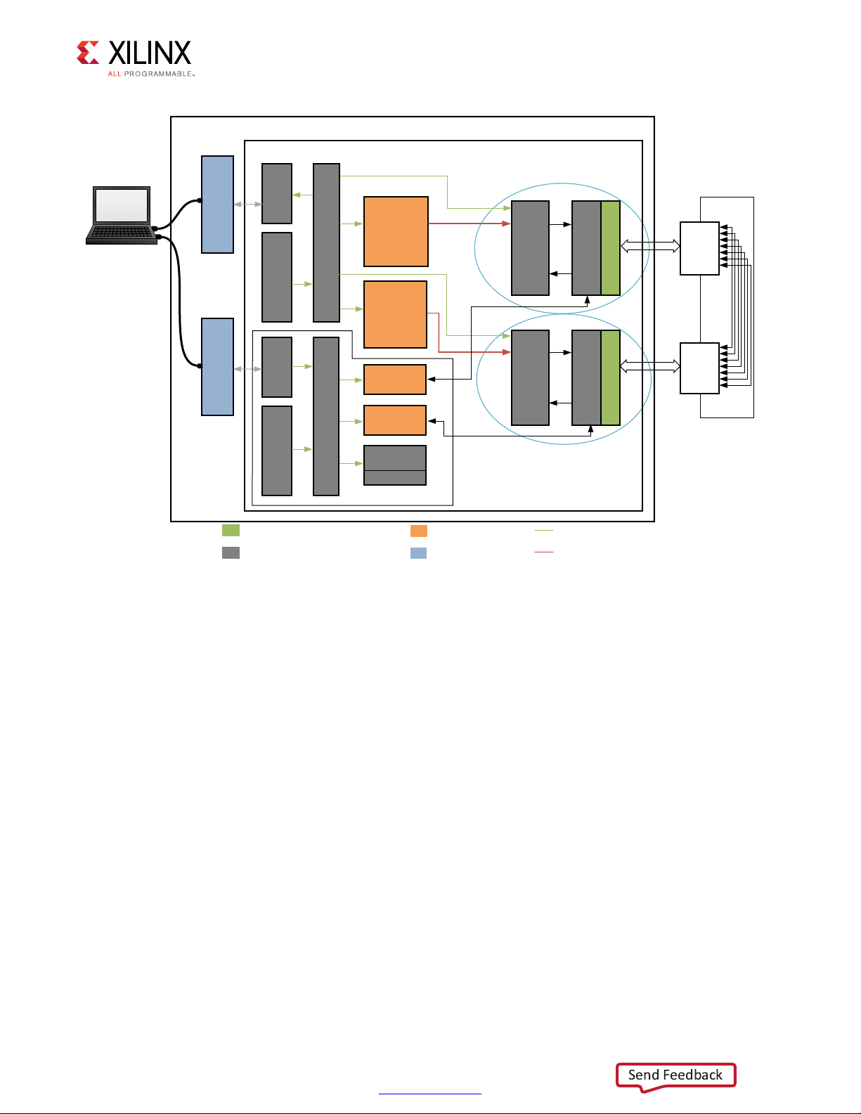
The 10GBASE-KR TRD (Figure 1-1) targets the Kintex® UltraScale™ XCKU040-2FFVA1156C
FPGA running on the KCU1250 characterization board. It demonstrates connectivity
between the 10-Gigabit Ethernet PCS/PMA IP core (10GBASE-KR) and the 10-Gigabit
Ethernet MAC IP core (10G MAC) and error free traffic flow on this 10-Gigabit Ethernet
channel across a backplane.
Chapter 1
10GBASE-KR Ethernet TRD 5
UG1058 (v2017.1) April 19, 2017
www.xilinx.com
Page 6
X-Ref Target - Figure 1-1
Integrated Blocks in FPGA
Xilinx IP
Custom Logic
On Board
AXI-Lite (Master to Slave)
AXI-Stream
SMA
Line
CARD
SMA
Line
CARD
Backplane
KCU1250 Board
CHANNEL 1
CHANNEL 0
C
C
0
XCKU040-2FFGA1156C FPGA
64 bits
XGMII
64 bits at 156.25MHz
10GBASE -KR
64 bits at 156.25MHz
AXI Interconnect
AXI UART
Lite
MicroBlaze
Subsystem
64 bits
XGMII
10G
MAC
10GBASE -KR
GTH Transceiver
AXI LITE
10G
MAC
AXI LITE
GTH Transceiver
To the
UART
Java GUI/Driver
and Vivado
Design Suite
USB -UART
SiLabs CP2105
Control
Computer
Traffic
Generator
and
Monitor
Traffic
Generator
and
Monitor
USB -JTAG
AXI Interconnect
JTAG to
AXI
MicroBlaze
Subsystem
AXI DRP
Bridge
AXI BRAM
Controller
BRAM
AXI DRP
Bridge
DRP
DRP
Eyescan System
X18426-120716
Send Feedback
Chapter 1: Introduction
HANNEL 1
HANNEL
Figure 1-1: The 10GBASE-KR TRD
10GBASE-KR is defined in IEEE Std 802.3-2012 [Ref 1]. It specifies the 10 Gb/s physical layer
specification using 10GBASE-R encoding over an electrical backplane.
The 10GBASE-KR TRD has two 10 Gb/s Ethernet channels; channel 0 and channel 1. Transmit
data is generated by the Traffic Generator and Monitor block. Data from one channel is
looped back to the other channel on a backplane through SMA cables as shown in
Figure 3-2. The looped-back data becomes the receive data on the other channel and the
frame length and frame check sequence (FCS) are verified by the 10-Gigabit Ethernet MAC
IP core.
A MicroBlaze™ processor subsystem monitors the 10-Gigabit Ethernet MAC IP core
statistics. It also controls the Traffic Generator and Monitor block and reports Ethernet
performance. It passes this information to the Ethernet Controller application GUI running
on the control computer via the USB-to-UART port on the KCU1250 board.
10GBASE-KR Ethernet TRD 6
UG1058 (v2017.1) April 19, 2017
www.xilinx.com
Page 7

Components, Features, and Functions
Send Feedback
The 10GBASE-KR TRD includes:
• 10-Gigabit Ethernet PCS/PMA IP core (10GBASE-KR):
Uses GTH transceivers running at 10.3125 Gb/s line rate.
°
Provides a single data rate (SDR) 10-Gigabit Ethernet Media Independent Interface
°
(XGMII) which connects to the 10-Gigabit Ethernet MAC IP core. The XGMII interface
runs at 156.25 MHz and the data path is 64-bits wide.
Provides a serial interface to connect to the backplane.
°
Auto-negotiation (AN) and forward error connection (FEC) is enabled.
°
Is monitored and configured through status and configuration vectors.
°
• 10-Gigabit Ethernet MAC IP core (10G MAC):
Connects to the 10-Gigabit Ethernet PCS/PMA IP core using the XGMII interface.
°
Provides AXI4-Stream protocol support on the user interface running at
°
156.25 MHz.
Chapter 1: Introduction
Is monitored through an AXI4-Lite interface.
°
• Traffic Generator and Monitor:
Generates Ethernet traffic.
°
Monitors bandwidth utilization on the transmit and receive AXI4-Stream interfaces
°
of the 10-Gigabit Ethernet MAC IP core.
Is configured and monitored through an AXI4-Lite interface.
°
•AXI UART Lite:
Provides the controller interface for asynchronous serial data transfer. This interface
°
connects to the USB-to-UART port on the KCU1250 board, and is used to
communicate with the control computer.
Provides an AXI4-Lite interface to communicate with the MicroBlaze processor
°
subsystem.
• MicroBlaze processor subsystem and AXI Interconnect:
Communicates with the 10-Gigabit Ethernet MAC IP core, Traffic Generator and
°
Monitor, and AXI UART Lite using the AXI4-Lite protocol.
Drivers running on the MicroBlaze processor subsystem interpret commands
°
received from the Ethernet Controller application GUI running on the control
computer and convert them to AXI4-Lite transactions.
10GBASE-KR Ethernet TRD 7
UG1058 (v2017.1) April 19, 2017
www.xilinx.com
Page 8

• Ethernet Controller application GUI/Driver:
Send Feedback
Provides a graphical user interface running on the control computer to pass user
°
inputs to the 10GBASE-KR TRD and to display status through the KCU1250 board
USB-to-UART port.
• Eye scan system:
AXI DRP bridge:
°
- Custom logic that allows access to DRP registers of the transceiver through any
AXI master such as the MicroBlaze processor subsystem.
AXI block RAM controller:
°
- An AXI slave IP core that allows access to local block RAM by AXI master devices
such as the MicroBlaze processor subsystem and the JTAG to AXI Master IP core.
- The block RAM stores the data read from the DRP port of the transceiver.
JTAG to AXI Master:
°
- An AXI Master IP core that can generate AXI transactions and drive AXI signals
internal to FPGA in the system.
Chapter 1: Introduction
- Communicates with the AXI block RAM controller via the AXI Interconnect.
- Allows the Vivado® tools logic analyzer Tcl console running on the control
computer to interact with FPGA through the USB-to-JTAG port on the KCU1250
board.
MicroBlaze processor subsystem:
°
- An AXI Master that communicates with the AXI DRP bridge and AXI block RAM
controller via the AXI Interconnect.
- Drivers running on the MicroBlaze processor subsystem implement an algorithm
to measure a statistical eye (bit error ratio (BER) versus time and voltage offset).
Data sampling points are available to read via the DRP port of the transceiver.
Point-by-point measured data is stored in a block RAM to be burst read by the
control computer via the JTAG to AXI Master.
AXI Interconnect:
°
- Allows multiple AXI masters (MicroBlaze processor subsystem and JTAG to AXI
Master) to communicate with multiple AXI slaves (AXI DRP Bridge and AXI block
RAM controller).
10GBASE-KR Ethernet TRD 8
UG1058 (v2017.1) April 19, 2017
www.xilinx.com
Page 9
Chapter 1: Introduction
Send Feedback
Resource Utilization
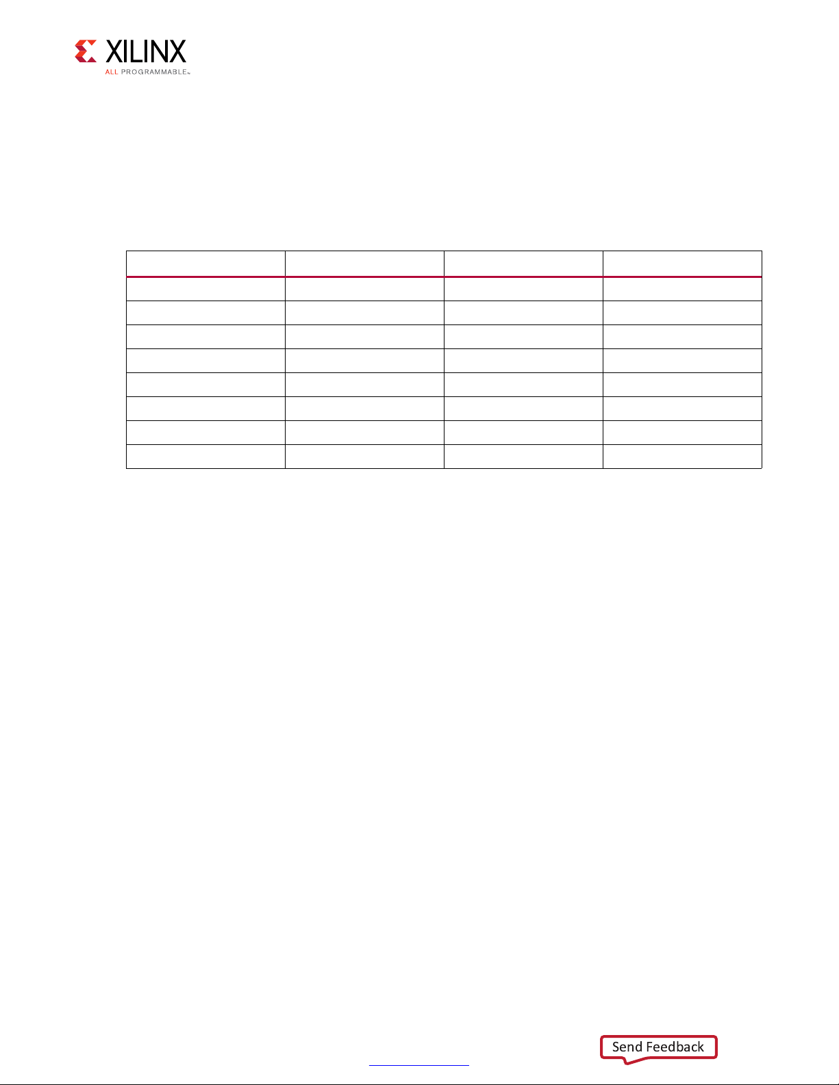
Table 1-1 lists the resources used by the 10GBASE-KR TRD after synthesis has run. Place and
route can alter these numbers based on placements and routing paths, so use these
numbers as a rough estimate of resource utilization. These numbers might vary based on
the version of the 10GBASE-KR TRD and the tools used to regenerate the design.
Table 1-1: 10GBASE-KR TRD Resource Utilization
Site Type Used Available Usage (%)
CLB LUTs 29,846 242,400 12.31
CLB Registers 41,794 484,800 8.62
Block RAM Tile 42 600 6.91
Global Clock Buffers 2 240 0.83
BUFG_GT_SYNC 6 55 10.90
BUFG_GT 6 120 5.00
GTHE3_CHANNEL 2 20 10.00
GTHE3_COMMON 2 5 40.00
10GBASE-KR Ethernet TRD 9
UG1058 (v2017.1) April 19, 2017
www.xilinx.com
Page 10

Setup
Send Feedback
This chapter lists the requirements and describes how to do all preliminary setup of the
KCU1250 board, control computer, and software before bringing up the 10GBASE-KR TRD.
IMPORTANT: Perform the procedures described in this chapter before performing the bring up
procedures described in Chapter 3, Bringing Up the Design.
Requirements
Hardware
• KCU1250 board with the Kintex® UltraScale™ XCKU040-2FFVA1156C FPGA [Ref 2]
Chapter 2
• Two USB cables, standard-A plug to micro-B plug
• Power Supply: 100 VAC–240 VAC input, 12 VDC 5.0A output
• Backplane: Z-Pack TINMAN Customer System kit from Tyco Electronics [Ref 3]
• Two Samtec Bulls Eye® cables from Avnet [Ref 4]
• Four DC Blocks/AC capacitors from Aeroflex [Ref 5]
Computer
One computer is required, and is identified as the control computer throughout this
document. It is required for running the Vivado® Design Suite, configuring the FPGA, and
running the Ethernet Controller application GUI to control and monitor the reference
design. It can be a laptop or desktop computer with Microsoft Windows 7 Operating
system.
Design Tools and Software
• Vivado Design Suite 2017.1
• USB UART drivers (CP210x VCP drivers) [Ref 6]
10GBASE-KR Ethernet TRD 10
UG1058 (v2017.1) April 19, 2017
•Tera Term [Ref 7]
www.xilinx.com
Page 11

Chapter 2: Setup
Send Feedback
• Java SE Runtime Environment 7
• Ethernet Controller application GUI (included with the 10GBASE-KR TRD)
• 10GBASE-KR Ethernet targeted reference design files
Download and installation instructions for each required software application and for the
10GBASE-KR Ethernet targeted reference design files are described in Preliminary Setup.
Preliminary Setup
Complete these tasks before bringing up the design described in Chapter 3, Bringing Up
the Design.
Install Vivado Design Suite
Install Vivado Design Suite 2017.1 on the control computer. Follow the installation
instructions provided in Vivado Design Suite User Guide Release Notes, Installation, and
Licensing (UG973) [Ref 8].
Note:
older version of Vivado tools, but the text and fields are still relevant to the current version.
Snapshots of the Vivado integrated design environment (IDE) in this document are from an
Download Targeted Reference Design Files
1. Download the 10GBASE-R TRD ZIP file rdf0310-kcu1250-trd05-2017-1.zip from
KCU1250 Characterization Kit Documentation.
2. Unzip the contents of the file to a working directory.
3. The unzipped contents will be located at
<working_dir>/kcu1250_10gbasekr_trd.
The 10GBASE-KR TRD directory structure is described in Appendix A, Directory Structure.
Install the USB UART Drivers
Download the CP210x USB to UART Bridge VCP drivers (for Windows 7) from Silicon Labs.
Follow the instructions in Silicon Labs CP210x USB-to-UART Installation Guide (UG1033)
[Ref 9].
10GBASE-KR Ethernet TRD 11
UG1058 (v2017.1) April 19, 2017
www.xilinx.com
Page 12

X-Ref Target - Figure 2-1
To U80
USB JTAG
J1
USB UART
USB cable
standard-A plug
to micro-B plug
J28 12 VDC
Power Supply
100VAC–240VAC Input
12 VDC 5.0A Output
ON
OFF
Board
Power
Switch SW1
Wally
&RQWURO
&RPSXWHU
X18427-120716
Send Feedback
Chapter 2: Setup
Configure the Control Computer COM Port
The TRD uses the Tera Term Pro terminal emulator and the Ethernet Controller application
GUI to communicate between the control computer and the KCU1250 board. To configure
the control computer COM ports for this purpose:
1. Place switch SW1 to the OFF position. (SW1 in Figure 2-1).
2. Connect the KCU1250 board to the control computer and power supply as shown in
Figure 2-1.
TIP: Figure 2-1 shows only the top edge of the KCU1250 board.
10GBASE-KR Ethernet TRD 12
UG1058 (v2017.1) April 19, 2017
Figure 2-1: Connections for Preliminary Setup
3. Power on the KCU1250 board by placing switch SW1 to the ON position. (SW1 in
Figure 2-1).
www.xilinx.com
Page 13
Chapter 2: Setup
X18434-120716
Send Feedback
4. Open the control computer Device Manager. In the Windows task bar, click Start, click
Control Panel, and then click Device Manager.
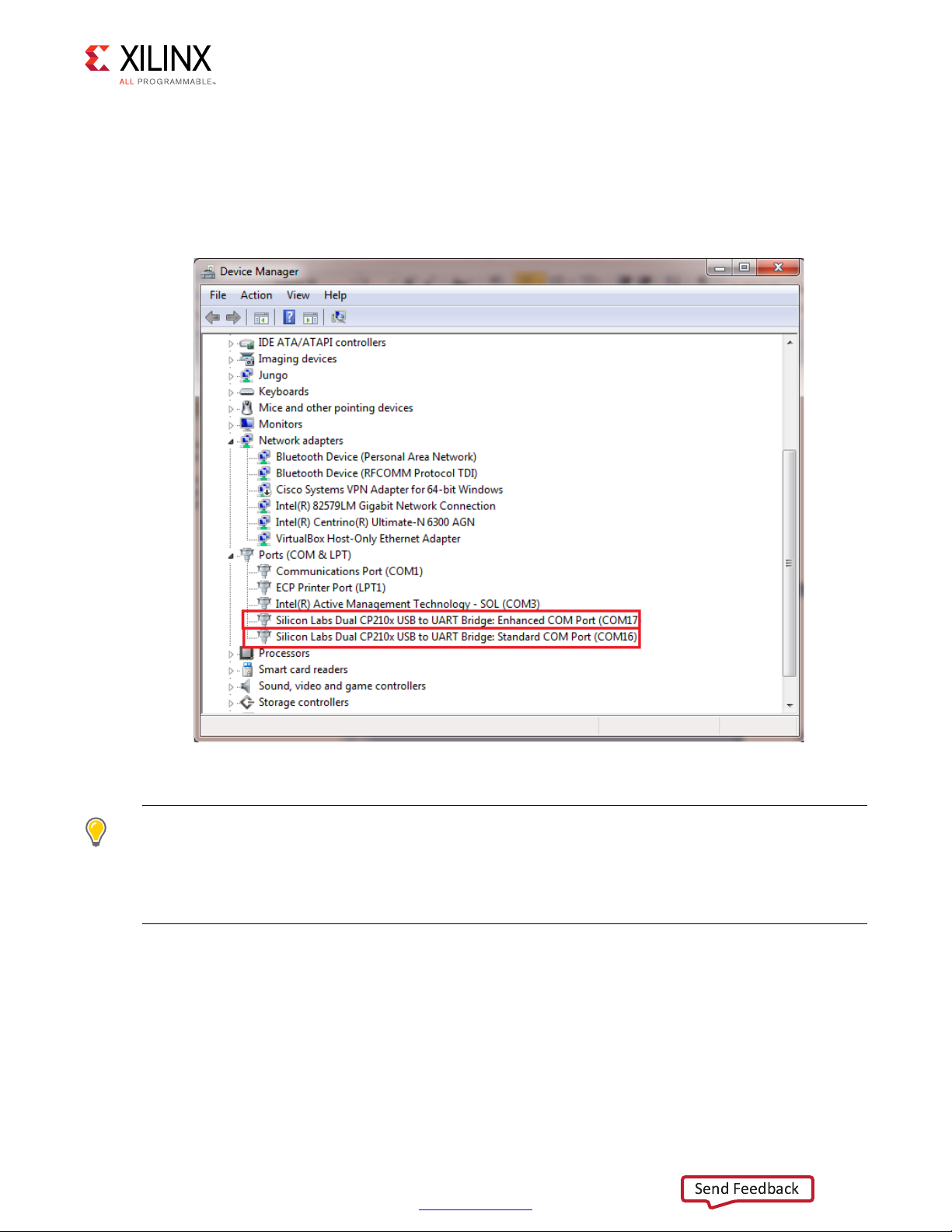
5. In the Device Manager window (Figure 2-2), expand Ports (COM & LPT), right-click
Silicon Labs CP210x USB to UART Bridge: Standard COM Port, and then click
Properties.
X-Ref Target - Figure 2-2
10GBASE-KR Ethernet TRD 13
UG1058 (v2017.1) April 19, 2017
Figure 2-2: Device Manager
TIP: Make note of the COM port numbers assigned by the cont rol com puter OS in your setup to Silicon
Labs CP210x USB to UART Bridge: Standard COM Port and Silicon Labs CP210x USB to UART
Bridge: Enhanced COM Port. The Enhanced COM port number must be provided to the Tera Term Pro
terminal emulator in step 2, page 15. The Standard COM port number must be provided to the Ethernet
Controller application in step 2, page 31.
www.xilinx.com
Page 14
Chapter 2: Setup
X18435-120716
Send Feedback
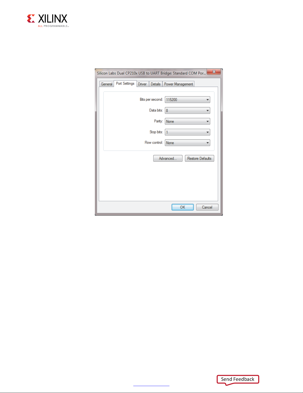
6. In the properties window, select the Port Settings tab (Figure 2-3).
7. Set Bits per second, Data bits, Parity, Stop bits, and Flow control to the values shown
in Figure 2-3, and click OK.
X-Ref Target - Figure 2-3
Figure 2-3: Port Settings
8. In the Device Manager window (Figure 2-2), expand Ports (COM & LPT), right-click
Silicon Labs CP210x USB to UART Bridge: Enhanced COM Port and then click
Properties.
9. In the properties window, select the Port Settings tab and set Bits per second, Data
bits, Parity, Stop bits, and Flow control to the values shown in (Figure 2-3), and then
click OK.
10GBASE-KR Ethernet TRD 14
UG1058 (v2017.1) April 19, 2017
www.xilinx.com
Page 15
Chapter 2: Setup
;
Send Feedback
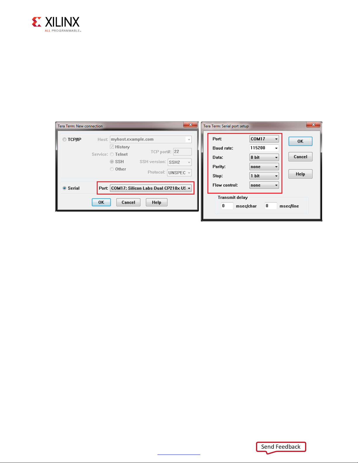
Instal l Tera Term Pro Software
1. Follow the download and installation instructions provided in Tera Term Terminal
Emulator Installation Guide (UG1036) [Ref 10].
2. To communicate with the KCU1250 board, configure the new Tera Term connection and
serial port settings as shown in Figure 2-4. These settings must match the control
computer COM port settings shown in Figure 2-3. Select the serial COM port associated
with Silicon Labs Dual CP210x USB to UART Bridge: Enhanced COM Port.
X-Ref Target - Figure 2-4
Figure 2-4: Tera Ter m Pro S e t ting s
Install Java
Download Java SE Runtime Environment 7 from Oracle [Ref 11] and install the program on
the control computer. Follow the installation instructions provided with the software.
10GBASE-KR Ethernet TRD 15
UG1058 (v2017.1) April 19, 2017
www.xilinx.com
Page 16

X-Ref Target - Figure 2-5
X18437-120716
Send Feedback
Chapter 2: Setup
Install the Ethernet Controller Application
1. Browse to <working_dir>/kcu1250_10gbasekr_trd/software/GUI
(Figure 2-5).
Figure 2-5: Directory Location, Ethernet Controller Installer
2. Right-click either the EthernetController-32-installer (for a 32-bit operating system)
or EthernetController-64-installer (for a 64-bit operating system) and select Run as
administrator (Figure 2-5).
3. Click Yes in the dialog box that opens.
10GBASE-KR Ethernet TRD 16
UG1058 (v2017.1) April 19, 2017
www.xilinx.com
Page 17
Chapter 2: Setup
X18438-120716
X18439-120716
Send Feedback
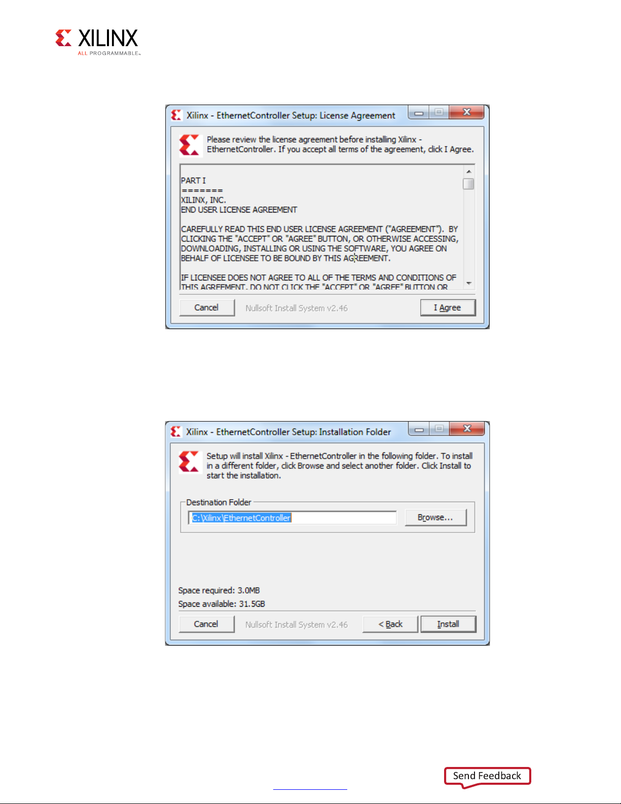
4. In the License Agreement display (Figure 2-6), click I Agree to continue installation.
X-Ref Target - Figure 2-6
Figure 2-6: License Agreement
5. Browse to the location where the Ethernet Controller application will be installed and
click Install (Figure 2-7).
X-Ref Target - Figure 2-7
10GBASE-KR Ethernet TRD 17
UG1058 (v2017.1) April 19, 2017
Figure 2-7: Ethernet Controller Installation Location
www.xilinx.com
Page 18
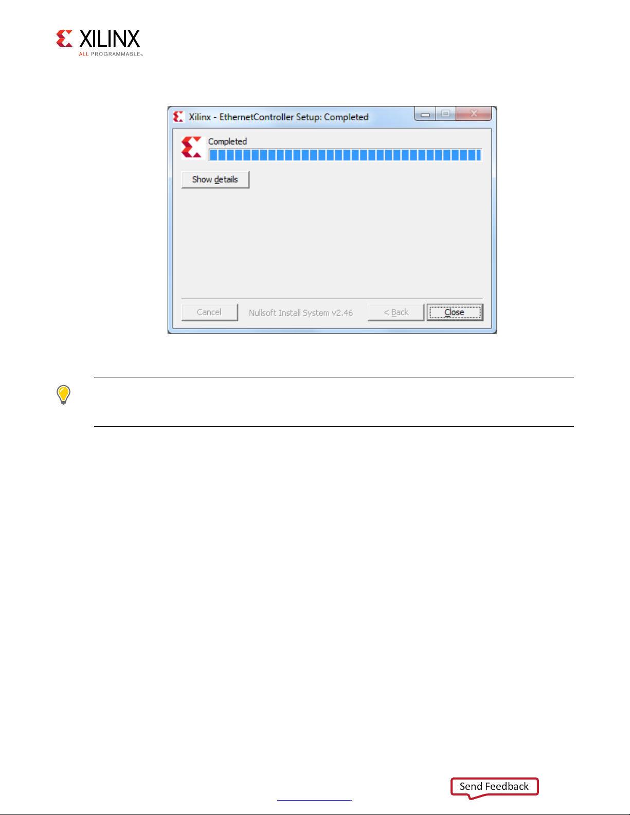
6. Click Close after installation is complete (Figure 2-8).
X18440-120716
Send Feedback
X-Ref Target - Figure 2-8
Chapter 2: Setup
Figure 2-8: Installation Complete
TIP: To uninstall the Ethernet Controller application after design bring up, open the Control Panel. In
the Control Panel click All Control Panel Items > Programs and Features and uninstall program
Xilinx Ethernet Controller - Powered by Xilinx.
Ready to Bring Up the Design
After all procedures in this chapter are complete, go to Chapter 3, Bringing Up the Design.
10GBASE-KR Ethernet TRD 18
UG1058 (v2017.1) April 19, 2017
www.xilinx.com
Page 19
Bringing Up the Design
Send Feedback
This chapter describes how to bring up the 10GBASE-KR TRD. Instructions are provided for
setting up the KCU1250 board and backplane, programming the clock, programming the
FPGA, configuring virtual input/output (VIO), and running the Ethernet Controller
application.
IMPORTANT: Perform the preliminary setup procedures described in Chapter 2, Setup before
performing the bring up procedures described in this chapter.
Set Up the KCU1250 Board
Chapter 3
Connect Bulls Eye Cables
1. Connect the SAMTEC Bulls Eye cables to J41 (GTH Transceiver Quad_226) and J42 (GTH
Transceiver Quad_227) as described in this video:
VIDEO: New GTX/GTH/GTZ Interconnect on Xilinx Characterization Boards
2. The Bulls Eye SMA cables are numbered. Cable 15 is TX0_P, cable 16 is TX0_N, cable 17
is RX0_P and cable 18 is RX0_N. Connect the AC capacitors (Aeroflex SMA DC Blocks—
[Ref 5]) to TXN and TXP SMA connector on both Bulls Eye cables. Refer to pages 51 and
52 of the KCU1250 Characterization Board Schematics (XTP398) [Ref 12].
10GBASE-KR Ethernet TRD 19
UG1058 (v2017.1) April 19, 2017
www.xilinx.com
Page 20

X-Ref Target - Figure 3-1
COL6
COUNTER
BORED
COL6
COUNTER
BORED
Trace Length 16"
TYCO BACKPLANE
RX0_P – SMA 17
TX0_P – SMA 15
TX0_N – SMA 16
RX0_N – SMA 18
J41
GT X0Y8
Bank 226
TX0_P – SMA 15
RX0_P – SMA 17
RX0_N – SMA 18
TX0_N – SMA 16
J42
GT X0Y12
Bank 227
Transmit
Receive
X18441-120716
Send Feedback
Chapter 3: Bringing Up the Design
3. Connect the SMA cables on the Bulls Eye connector to the Tyco backplane as shown in
Figure 3-1.
Figure 3-1: SMA Connections to the Backplane
4. SMA cable 19 is REFCLK0_C_P and cable 20 is REFCLK0_C_N. Connect cable 19 and cable
20 from J41 to the clock out pins of Oscillator Si5368 on the Superclock module.
Connect cable 19 and cable 20 from J42 to the clock out pins of Oscillator Si570 on the
Superclock module.
5. Connect the power supply to the KCU1250 board.
6. Connect one end of the Micro-USB cable to USB-UART port (J1) and the other to the
Control PC.
7. Connect one end of the Micro-USB cable to USB-JTAG port (U80) and the other to the
Control PC.
10GBASE-KR Ethernet TRD 20
UG1058 (v2017.1) April 19, 2017
www.xilinx.com
Page 21

X-Ref Target - Figure 3-2
Power Supply
100VAC–240VAC Input
12 VDC 5.0A Output
Board
Power
Switch
SW1
To U80
USB JTAG
J1
USB UART
USB cable
standard-A plug
to micro-B plug
Connect SMA cables
15,16,17 and 18 from
J42 to the backpane
Connect SMA cables
15,16,17 and 18 from
J41 to the backpane
Connect AC caps
toTXN/TXP SMAs
Connect AC caps
toTXN/TXP SMAs
Connect SMA
cables 19 and 20
from J41 to Si5368
Connect SMA
cables 19 and 20
from J42 to Si570
Super-Clock II
Module
J41J42
Wally
&RQWURO
&RPSXWHU
X18442-120716
Send Feedback
Chapter 3: Bringing Up the Design
All above connections are shown in Figure 3-2.
Figure 3-2: KCU1250 Board Connections Including SMA Connections to the Backplane
8. Power on the KCU1250 board by placing switch SW1 to the ON position.
10GBASE-KR Ethernet TRD 21
UG1058 (v2017.1) April 19, 2017
www.xilinx.com
Page 22

Chapter 3: Bringing Up the Design
X18443-120716
Send Feedback
Program the Clocks Sources
The KCU1250 board uses the SuperClock-2 module to provides programmable, low-noise
and low-jitter clock sources for the KCU1250 board. See HW-CLK-101-SCLK2 SuperClock-2
Module User Guide (UG770) [Ref 13] for more information.
To program the clock sources:
1. On the control computer, open the Tera Term Pro terminal program. Click Start > All
Programs > Tera Term > Tera Term.
2. In the New connection window, configure the settings as shown in Figure 3-3. Select the
serial COM port associated with Silicon Labs Dual CP210x USB to UART Bridge: Enhanced COM Port.
Click OK.
X-Ref Target - Figure 3-3
10GBASE-KR Ethernet TRD 22
UG1058 (v2017.1) April 19, 2017
Figure 3-3: Connect to Enhanced COM Port on Tera Term
3. On the control computer keyboard, press the Enter key. The Tera Term window will
display the SuperClock-2 configuration menu.
4. Set Programmable Clocks:
a. Select option 1 (Set Programmable Clocks): Type 1, and press Enter.
5. Set the Si570 frequency to 156.25 MHz:
a. Select option 1 (Set KCU1250 Si570 frequency): Type 1, and press Enter.
www.xilinx.com
Page 23
Chapter 3: Bringing Up the Design
X18444-120716
Send Feedback
b. Enter the Si570 frequency in MHz: Type 156.25 and press Enter.
6. Set the Si5368 frequency to 156.25 MHz:
a. Select option 2 (Set KCU1250 Si5368 frequency): Type 2, and press Enter.
b. Enter the Si5368 frequency in MHz: Type 156.25 and press Enter.
c. Choose Si5368 operating mode (Select Free-Run using XA-XB crystal): Type 2, and
press Enter.
7. Close the Tera Term Pro terminal program window.
Program the FPGA
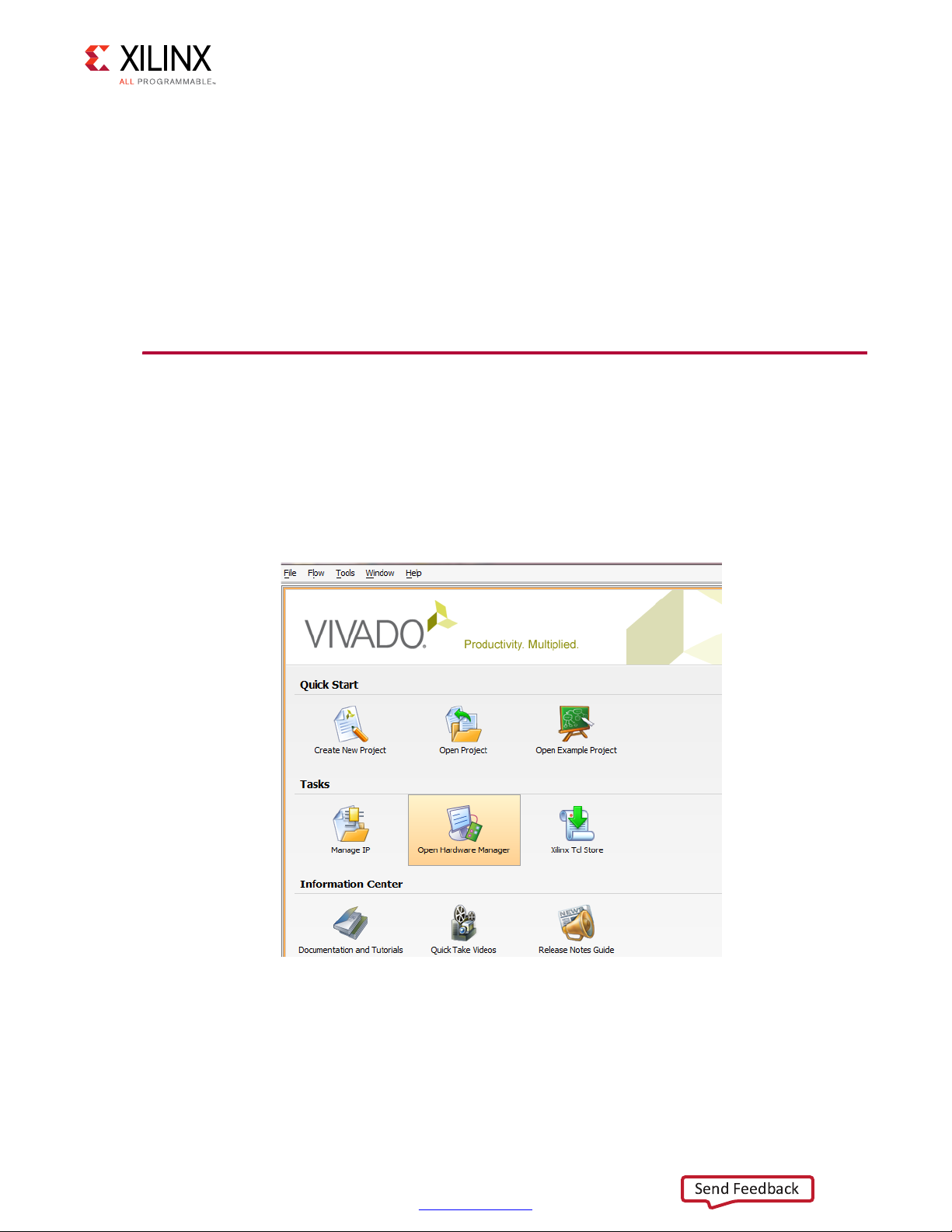
1. Launch the Vivado® Integrated Design Environment (IDE) on the control computer:
a. In Windows, select Start > All Programs > Xilinx Design Tools >
Vivado 2017.1 > Vivado 2017.1.
b. On the getting started page, click Open Hardware Manager (Figure 3-4).
X-Ref Target - Figure 3-4
10GBASE-KR Ethernet TRD 23
UG1058 (v2017.1) April 19, 2017
Figure 3-4: Open Hardware Manager
www.xilinx.com
Page 24
Chapter 3: Bringing Up the Design
X18445-120716
X18446-120716
Send Feedback
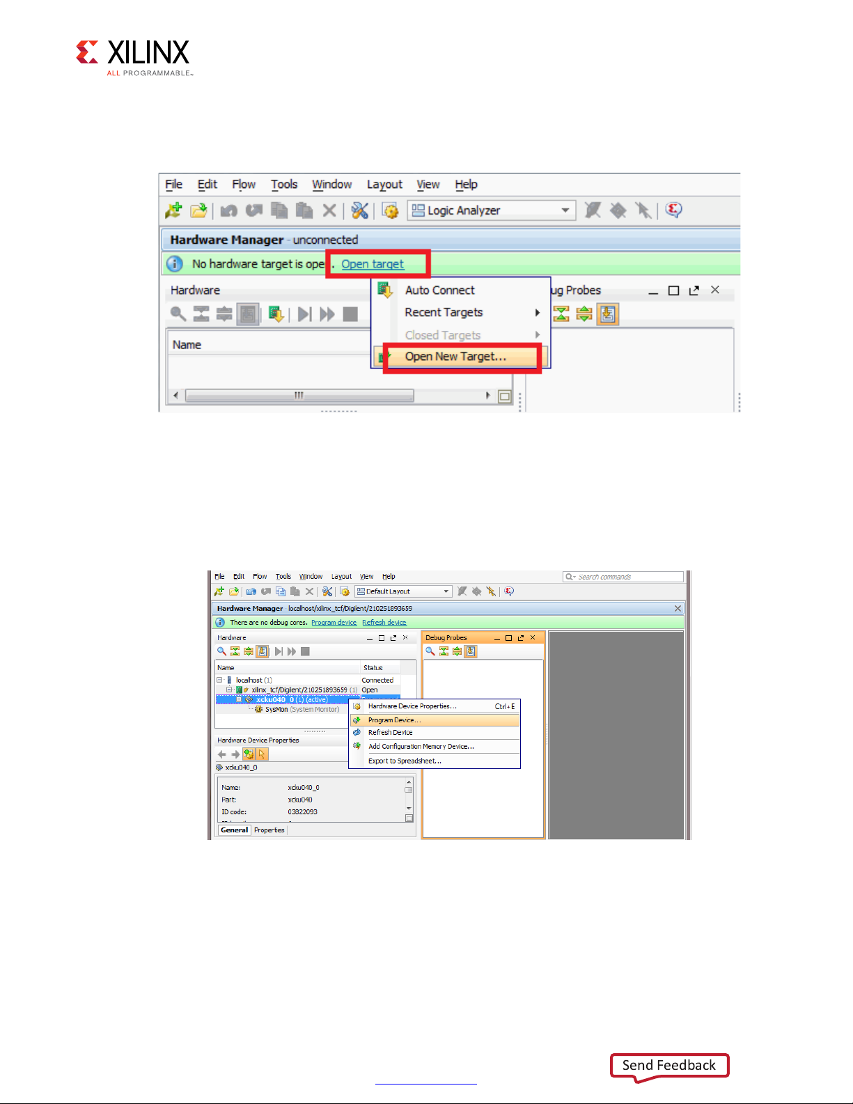
2. Open the connection wizard to initiate a connection to the KCU1250 board:
a. Click Open a new hardware target (Figure 3-5).
X-Ref Target - Figure 3-5
Figure 3-5: Open a New Hardware Target
b. Configure the wizard to establish connection with the KCU1250 board by selecting
the default value on each wizard page. Click Next > Next > Next > Finish.
c. In the hardware view, right-click xcku040 and click Program Device (Figure 3-6).
X-Ref Target - Figure 3-6
Figure 3-6: Select Device to Program
10GBASE-KR Ethernet TRD 24
UG1058 (v2017.1) April 19, 2017
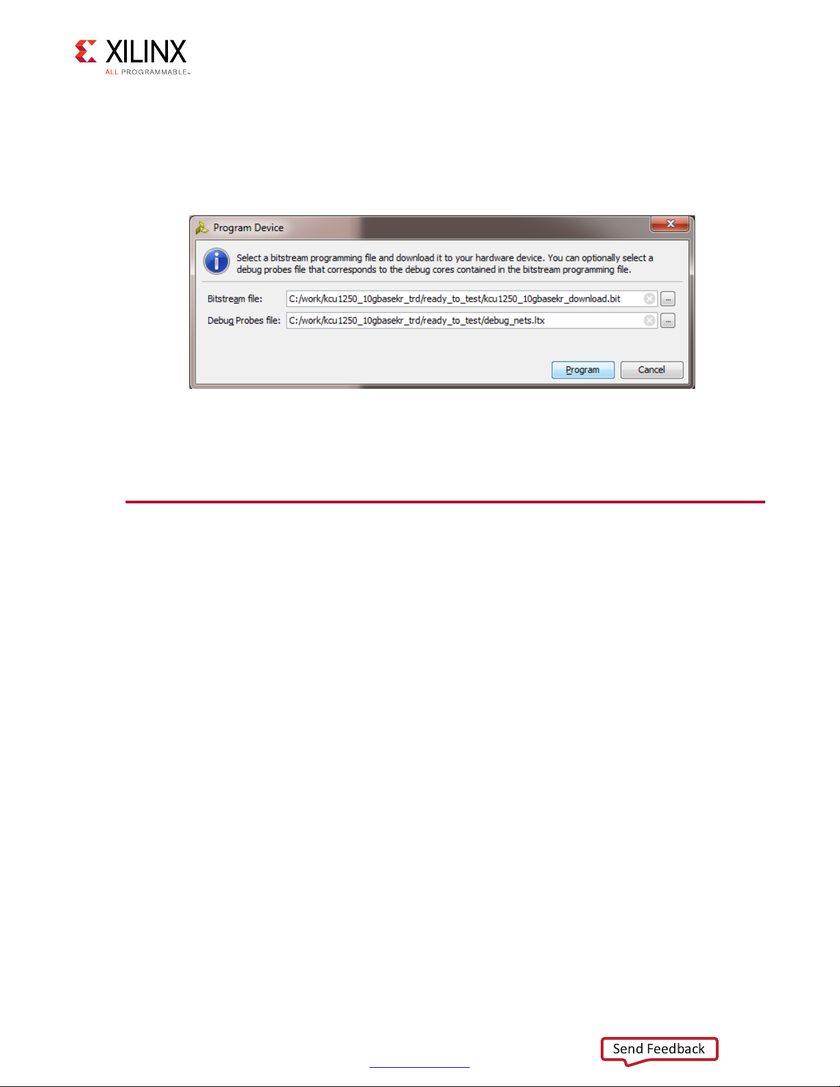
d. In the Bitstream file field, browse to the location of the BIT file:
<working_dir>/kcu1250_10gbasekr_trd/ready_to_test/kcu1250_10gb
asekr_download.bit
www.xilinx.com
Page 25
Chapter 3: Bringing Up the Design
X18447-120716
Send Feedback
e. In the Debug Probes file field, browse to the location of the probes file:
<working_dir>/kcu1250_10gbasekr_trd/ready_to_test/debug_nets.ltx
and click Program (Figure 3-7).
X-Ref Target - Figure 3-7
Figure 3-7: Program Device Window
After completing these steps, continue on to Configure VIO.
Configure VIO
There are six virtual I/O (VIO) cores in the reference design. After programming, each VIO
core can be controlled in the Vivado IDE. To add probes to each VIO window:
1. Open the VIO dashboard. On the top panel of the Vivado IDE, click Window >
Dashboard > Reset to default.
2. Open the Debug Probes window: on the top panel of the Vivado IDE click Window >
Debug Probes.
3. In the Debug Probes window, right click on hw_vio_1 and select Add probes to VIO
Window (Figure 3-8).
4. Repeat the same procedure for hw_vio_2, hw_vio_3, hw_vio_4, hw_vio_5 and
hw_vio_6.
10GBASE-KR Ethernet TRD 25
UG1058 (v2017.1) April 19, 2017
www.xilinx.com
Page 26

X-Ref Target - Figure 3-8Add probes to the VIO dashboard
X18448-120716
Send Feedback
Chapter 3: Bringing Up the Design
Figure 3-8: Adding a Probe to a VIO Window
Table 3-1 shows what each VIO window configures and monitors.
Table 3-1: VIO Tab Mapping
VIO Tab Mapping Comments
hw_vio_6
hw_vio_5
hw_vio_4
hw_vio_3
hw_vio_2
hw_vio_1
Notes:
1. The value of n in hw_vio_n might change based on how the Vivado Synthesis tool processes the netlist. You might have to
redo the above mapping accordingly.
(1)
(1)
(1)
(1)
(1)
(1)
training_*_ch1
training_*_ch0
stat_ch1_*
stat_ch0_*
ch1_*
ch0_*
Configures the DRP port for channel 1 through the training port of the
10-Gigabit Ethernet PCS/PMA IP core.
Configures the DRP port for channel 0 through the training port of the
10-Gigabit Ethernet PCS/PMA IP core.
Monitors the status vector signals of the 10-Gigabit Ethernet PCS/PMA
IP core for channel 1.
Monitors the status vector signals of the 10-Gigabit Ethernet PCS/PMA
IP core for channel 0.
Configures the configuration vector signals of the 10-Gigabit Ethernet
PCS/PMA IP core for channel 1.
Configures the configuration vector signals of the 10-Gigabit Ethernet
PCS/PMA IP core for channel 0.
10GBASE-KR Ethernet TRD 26
UG1058 (v2017.1) April 19, 2017
www.xilinx.com
Page 27

X-Ref Target - Figure 3-9
X18449-120716
Send Feedback
Chapter 3: Bringing Up the Design
5. Verify if stat_ch0_pcs_rx_link_status and stat_ch1_pcs_rx_link_status is 1. This indicates
that the 10GBASE-R link is up (Figure 3-9).
10GBASE-KR Ethernet TRD 27
UG1058 (v2017.1) April 19, 2017
Figure 3-9: Verify Link Status
6. Enable FEC, Training and Auto Negotiation on both channels by configuring signals in
the ch0_* and ch1_* VIO windows. Here is the sequence to follow:
a. Advertise Channel 1 is KR capable:
Set value 0080 on ch1_an_adv_data_31_16
b. Advertise Channel 1 supports FEC and is requesting FEC support from the partner:
Set value C000 on ch1_an_adv_data_47_32
c. Pulse ch1_an_ad to load the AN data bits for Channel 1:
Set value 1 on ch1_an_ad
Set value 0 on ch1_an_ad
d. Advertise Channel 0 is KR capable:
Set value 0080 on ch0_an_adv_data_31_16
e. Advertise Channel 0 supports FEC and is requesting FEC support from the partner:
Set value C000 on ch0_an_adv_data_47_32
www.xilinx.com
Page 28

Chapter 3: Bringing Up the Design
Send Feedback
f. Pulse ch0_an_ad to load the AN data bits for Channel 0:
Set value 1 on ch0_an_ad
Set value 0 on ch0_an_ad
g. Enable FEC on channel 1:
Set value 1 on ch1_enable_fec
h. Enable FEC on channel 0:
Set value 1 on ch0_enable_fec
i. Set Training done to 1 on channel 1. This indicates to Training Algorithm that the LP
transmitter has been successfully trained:
Set value 1 on ch1_training_done
j. Enable Training on channel 1:
Set value 1 on ch1_enable_training
IMPORTANT: Due to strict timing requirements on ch1_training_done, and the slow nature of executing
Tcl commands in Vivado, the ch1_training_done command is executed before the ch1_enable_training
command. This might not be true if executing these commands from a microprocessor.
k. Set Training done to 1 on channel 0. This indicates to the Training Algorithm that the
LP transmitter has been successfully trained:
Set value 1 on ch0_training_done
l. Enable Training on channel 0:
Set value 1 on ch0_enable_training
IMPORTANT: Due to strict timing requirements on ch0_training_done, and the slow nature of executing
Tcl commands in Vivado, the ch0_training_done command is executed before ch0_enable_training
command. This may not be true if executing these commands from a microprocessor.
m. Enable Auto Negotiation on channel 1:
Set value 1 on ch1_en_auto_negotiation
n. Enable Auto Negotiation on channel 0:
Set value 1 on ch0_en_auto_negotiation
o. Pulse Reset Auto Negotiation on channel 1:
Set value 1 on ch1_reset_autonegotiation, and then
Set value 0 on ch1_reset_autonegotiation
10GBASE-KR Ethernet TRD 28
UG1058 (v2017.1) April 19, 2017
IMPORTANT: Only reset one side of the channel. In this example, only Channel 1 is reset.
To toggle the VIO signals in the sequence as described in step 6 a Tcl script is provided
in:
<working_dir>/kcu1250_10gbasekr_trd/ready_to_test/en_fec_tr_an.tcl
www.xilinx.com
Page 29

Chapter 3: Bringing Up the Design
X18450-120716
Send Feedback
Source the script in the Tcl console of the Vivado IDE as shown in Figure 3-10.
X-Ref Target - Figure 3-10
10GBASE-KR Ethernet TRD 29
UG1058 (v2017.1) April 19, 2017
Figure 3-10: Source enable_fec_tr_an.tcl
www.xilinx.com
Page 30

X-Ref Target - Figure 3-11
X18451-120716
Send Feedback
Chapter 3: Bringing Up the Design
Verify if Auto Negotiation is complete (an_complete) and the 10GBASE-KR is negotiated
successfully in the stat_ch0* and stat_ch1* VIO windows (Figure 3-11). It should take only a
second or two for 10GBASE-KR IP core to negotiate successfully after executing the script.
Figure 3-11: AN Complete and KR Negotiated
10GBASE-KR Ethernet TRD 30
UG1058 (v2017.1) April 19, 2017
www.xilinx.com
Page 31

Chapter 3: Bringing Up the Design
X18452-120716
X18453-120716
Send Feedback
Running the Design
Launch the Ethernet Controller Application
1. Launch the Ethernet Controller application GUI on the control computer. In Windows,
click Start > All Programs > Xilinx > EthernetController (Figure 3-12).
X-Ref Target - Figure 3-12
Figure 3-12: Launch Ethernet Controller Application
2. Select the COM port associated with the Silicon Labs CP210x USB-to-UART
Bridge: Standard COM Port and click Connect (Figure 3-13) to open the Ethernet
Controller application for the 10GBASE-KR TRD.
TIP: The COM port associated with the Silicon Labs CP210x USB-to-UART Bridge: Standard COM Port
can be identified using the Windows device manager. See step 4, page 13.
X-Ref Target - Figure 3-13
Figure 3-13: Select COM Port Associated with the USB-to-UART Bridge
10GBASE-KR Ethernet TRD 31
UG1058 (v2017.1) April 19, 2017
www.xilinx.com
Page 32

X-Ref Target - Figure 3-14
X18454-120716
Send Feedback
Chapter 3: Bringing Up the Design
Running the Traffic Generators
1. Ethernet channel 0 and channel 1 are up and ready when the ETH0 PHY and ETH1 PHY
indicators are green (Figure 3-14). In the control panel for both channel 0 and channel 1,
select Internal Generator and enter 1500 in the payload field. Click Start.
Figure 3-14: Set Payload Size on Channel 0 and Channel 1
10GBASE-KR Ethernet TRD 32
UG1058 (v2017.1) April 19, 2017
www.xilinx.com
Page 33

X-Ref Target - Figure 3-15
X18455-120716
Send Feedback
Chapter 3: Bringing Up the Design
Figure 3-15 shows the performance achieved at this payload size is 9.74 Gb/s per
channel per direction. The allowed payload values that can be entered are 46 bytes to
1,500 bytes.
Figure 3-15: Throughput Performance Plots
TIP: The relationship between payload size and throughput can be demonstrated by changing the
payload size. Reducing the payload size causes a dip in performance. Refer to Appendix B, Performance
Estimates for performance estimation on 10G Ethernet protocol.
2. Stop traffic generation by clicking Stop for both channels.
10GBASE-KR Ethernet TRD 33
UG1058 (v2017.1) April 19, 2017
www.xilinx.com
Page 34

Chapter 3: Bringing Up the Design
X18456-120716
Send Feedback
3. Select the Channel 0 Statistics tab and verify if any packets were in error or were
dropped (Figure 3-16).
X-Ref Target - Figure 3-16
Figure 3-16: Channel 0 MAC Statistics
4. Next, select the Channel 1 Statistics tab and verify if any packets were in error or were
dropped (Figure 3-17):
The TX MAC statistics for Channel 0 should match the RX MAC statistics of
°
Channel 1.
The TX MAC statistics for Channel 1 should match the RX MAC statistics of
°
Channel 0.
10GBASE-KR Ethernet TRD 34
UG1058 (v2017.1) April 19, 2017
www.xilinx.com
Page 35

X-Ref Target - Figure 3-17
X18457-120716
Send Feedback
Chapter 3: Bringing Up the Design
Figure 3-17: Channel 1 MAC Statistics
5. Select the Performance Plots tab. Click Start for both channels to enable traffic
generation again. Run the instructions in the Generate Eye Scans section with traffic
running.
Generate Eye Scans
The JTAG to AXI Master IP core (hw_axi_1) allows the Vivado logic analyzer Tcl console
running on the control computer to interact with FPGA through the USB-to-JTAG port (U80)
on the KCU1250 board. The control computer periodically reads data samples via hw_axi_1
and creates an eye scan.
For more details refer to In-System Eye Scan of a PCI Express Link with Vivado IP Integrator
and AXI4 Application Note (XAPP1198) [Ref 14].
To generate an eye scan:
1. With traffic running in the Ethernet Controller application, source the
run_eyescan.tcl script in the Tcl console of the Vivado IDE (Figure 3-18). The
command to source the script is:
10GBASE-KR Ethernet TRD 35
UG1058 (v2017.1) April 19, 2017
source
<working_dir>/kcu1250_10gbasekr_trd/ready_to_test/eyescan/run_eyescan.tcl.
www.xilinx.com
Page 36

Chapter 3: Bringing Up the Design
X18458-120716
Send Feedback
IMPORTANT: Do not disconnect the USB-to-JTAG connection. This connection is required for the control
computer to interact with the JTAG to AXI Master IP core.
X-Ref Target - Figure 3-18
10GBASE-KR Ethernet TRD 36
UG1058 (v2017.1) April 19, 2017
Figure 3-18: Tcl S cri p t run_eyescan.tcl
www.xilinx.com
Page 37

Chapter 3: Bringing Up the Design
X18459-120716
Send Feedback
2. The run_eyescan command becomes available after the run_eyescan.tcl file is
sourced. To initiate a scan, type run_eyescan in the Tcl console (Figure 3-19). This
command initiates:
Vertical and Horizontal sweeps
°
Data sample collection
°
Data sample processing to create an eye scan
°
X-Ref Target - Figure 3-19
10GBASE-KR Ethernet TRD 37
UG1058 (v2017.1) April 19, 2017
Figure 3-19: The run_eyescan Command
www.xilinx.com
Page 38

X-Ref Target - Figure 3-20
X18460-120716
Send Feedback
Chapter 3: Bringing Up the Design
3. The scan plots for Channel 0 and Channel 1 are shown in Figure 3-20.
NOTE: The Scan Plot for Channel 0 was dragged to a new Vertical group.
Figure 3-20: Eye Scan for Channel 0 and Channel 1
Forward Error Correction
To showcase forward error correction, a 10-Gigabit Ethernet PCS/PMA IP file has been
modified to inject errors in the GTH transceiver parallel data via VIO. The unmodified file is
located at:
<working_directory>/kcu1250_10gbase_kr/hardware/vivado/runs/
impl_run/10gbasekr_trd.srcs/sources_1/bd/mac_phy/ip/
mac_phy_ten_gig_eth_pcs_pma_ch0_0/
synth/mac_phy_ten_gig_eth_pcs_pma_ch0_0_block.v
A demo BIT file is provided with the 10GBASE-KR TRD to inject errors and verify if the
Forward Error Correction (FEC) block is working as expected.
To program the FPGA with this demo:
1. Repeat Set Up the KCU1250 Board.
10GBASE-KR Ethernet TRD 38
UG1058 (v2017.1) April 19, 2017
www.xilinx.com
Page 39

Chapter 3: Bringing Up the Design
X18461-120716
Send Feedback
2. Repeat Program the Clocks Sources.
3. Repeat step 1, page 23 and step 2, page 24 listed under Program the FPGA.
4. Program the FPGA:
a. In the Bitstream file field, browse to the location of the BIT file:
<working_dir>/kcu1250_10gbasekr_trd/ready_to_test/fec_and_err_
injection/kcu1250_10gbasekr_download.bit
b. In the Debug Probes file field, browse to the location of the LTX file:
<working_dir>/kcu1250_10gbasekr_trd/ready_to_test/
fec_and_err_injection/debug_nets.ltx
c. Click Program (Figure 3-21).
X-Ref Target - Figure 3-21
Figure 3-21: Program Device Window
There are seven VIO cores in the reference design. After programming, they can be
controlled in the Vivado IDE. To add probes to each VIO window:
1. Open the VIO dashboard. On the top panel of the Vivado IDE, click Window >
Dashboard > Reset to default.
2. Open the Debug Probes window: on the top panel of the Vivado IDE click Window >
Debug Probes.
3. In the Debug Probes window, right click on hw_vio_1 and select Add probes to VIO
Window.
4. Repeat the same procedure for hw_vio_2, hw_vio_3, hw_vio_4, hw_vio_5, hw_vio_6, and
hw_vio_7.
10GBASE-KR Ethernet TRD 39
UG1058 (v2017.1) April 19, 2017
www.xilinx.com
Page 40

Chapter 3: Bringing Up the Design
Send Feedback
Table 3-2 shows what each VIO dashboard configures and monitors.
Table 3-2: VIO Dashboard Mapping for the FEC and Error Injection BIT File
VIO Dashboard Mapping Comments
hw_vio_7
hw_vio_6
hw_vio_5
hw_vio_4
hw_vio_3
hw_vio_2
hw_vio_1
Notes:
1. The value of n in hw_vio_n might change based on how the Vivado Synthesis tool processes the netlist. You might
have to redo the above mapping accordingly.
(1)
(1)
(1)
(1)
(1)
(1)
(1)
training_*_ch1
training_*_ch0
stat_ch1_*
stat_ch0_*
ch1_*
ch0_*
insert_*_bit_error_*
Configures the DRP port for channel 1 through the training
port of 10G Ethernet PCS-PMA IP.
Configures the DRP port for channel 0 through the training
port of 10G Ethernet PCS-PMA IP.
Monitors the status vector signals of 10G Ethernet PCS-PMA
IP for channel 1.
Monitors the status vector signals of 10G Ethernet PCS-PMA
IP for channel 0.
Configures the configuration vector signals of 10G Ethernet
PCS-PMA IP for channel 1.
Configures the configuration vector signals of 10G Ethernet
PCS-PMA IP for channel 0.
Allows insertion of bit errors in transmit and receive data
streams of Channel 0.
5. Verify if stat_ch0_pcs_rx_link_status and stat_ch1_pcs_rx_link_status is 1. This indicates
that the 10GBASE-R link is up.
6. Enter the following Tcl script in the Vivado IDE to enable FEC, Training and Auto
Negotiation on both channels:
source <working_dir>/kcu1250_10gbasekr_trd/ready_to_test/enable_fec_tr_an.tcl
7. Verify if Auto Negotiation is complete (stat_ch*_an_complete) and 10GBASE-KR is
negotiated successfully (stat_ch*_bp_KR_negotiated) in stat_ch0* and stat_ch1* VIO
windows.
8. Repeat the steps in Running the Design.
9. In the ch1_* and ch0_* VIO windows, follow this sequence to insert errors in the data
stream:
a. In the ch1_* and ch0_* windows:
-Toggle (0>1>0) ch1_fec_corr_blocks
-Toggle (0>1>0) ch1_fec_uncorr_blocks
-Toggle (0>1>0) ch0_fec_corr_blocks
-Toggle (0>1>0) ch0_fec_uncorr_blocks
10GBASE-KR Ethernet TRD 40
UG1058 (v2017.1) April 19, 2017
www.xilinx.com
Page 41

Chapter 3: Bringing Up the Design
Send Feedback
This clears the stat_ch*_fec_corr_blocks and stat_ch*_fec_uncorr_blocks in the
stat_ch1_* and stat_ch0_* VIO windows.
b. In the insert_*_bit_error_* VIO window:
-Toggle (0>1>0) insert_single_bit_error_rx
- Verify the stat_ch0_fec_corr_blocks count goes up. Each toggle increases the
count value by 1.
c. In the insert_*_bit_error_* VIO window:
-Toggle (0>1>0) insert_single_bit_error_tx
- Verify the stat_ch1_fec_corr_blocks count goes up. Each toggle increases the
count value by 1.
d. In the Ethernet Controller application, click Stop and verify channel 0 MAC statistics
and channel 1 MAC statistics for errors or packet drops. There should be none.
e. In the Ethernet Controller application, click Start to enable traffic generation on
channel 0 and channel 1.
f. In the insert_*_bit_error_* VIO window,
- Set insert_multi_bit_rx_vector to h'FFF. This signal allows you to set the number
of bits which are in error in succession. A value of h'FFF indicates a burst of 12
bit errors.
-Toggle (0>1>0) insert_multi_bit_error_rx.
- Verify the stat_ch0_fec_uncorr_blocks count goes up. Each toggle increases the
count value by one.
IMPORTANT: If the number of contiguous '1' bits in the insert_multi_bit_rx_vector is set to less than 12,
then stat_ch0_fec_corr_blocks count goes up since the FEC block is capable of correcting a burst of 11
error bits.
g. In the insert_*_bit_error_* VIO window,
-Toggle (0>1>0) insert_multi_bit_error_tx. This signal causes a burst of 12
errors on the transmit data.
- Verify the stat_ch1_fec_uncorr_blocks count goes up. Each toggle increases the
count value by one.
h. In the Ethernet Controller application, click on Stop and verify Channel 0 MAC
statistics and Channel 1 MAC statistics for errors or packet drops. There will be errors
and the Frames Received count on the channels will not match up.
10GBASE-KR Ethernet TRD 41
UG1058 (v2017.1) April 19, 2017
www.xilinx.com
Page 42

Chapter 3: Bringing Up the Design
Send Feedback
To execute the sequence as described in step 9, a Tcl script is provided. Source the script in
the Tcl console of the Vivado IDE with the traffic running in the Ethernet Controller
application. The command to source the script is:
source
<working_dir>/kcu1250_10gbasekr_trd/ready_to_test/fec_and_err_injection/err_in
jection.tcl
Dynamic Reconfiguration Ports
The GTH transceiver dynamic reconfiguration ports (DRP) can be accessed via the training
ports of the 10-Gigabit Ethernet PCS/PMA IP core. The training ports are brought out to
VIOs - training_*_ch0 and training_*_ch1.
1. For reads:
Set the training_addr_ch* to a DRP address, example h'00_007F
°
(TX_MARGIN_FULL_1, TX_MARGIN_FULL_0)
Set the training_rnw_ch* to 1
°
Toggle (0>1>0) enable_ch*
°
The read value will be available on training_rd_data_reg_ch*
°
2. For writes:
Set the training_addr_ch* to a DRP address example h'00_007F
°
(TX_MARGIN_FULL_1, TX_MARGIN_FULL_0)
Set the training_wr_data for the above address as h'AE9C
°
Set the training_rnw_ch* to 0
°
Toggle (0>1>0) enable_ch*
°
Read the value back following the instructions for Reads to verify that the write was
°
successful
To execute the sequence described in step 1 and step 2, A Tcl script is provided in:
<working_dir>/kcu1250_10gbasekr_trd/ready_to_test/drp_rd_wr.tcl
Source the script in the Tcl console of the Vivado IDE.
10GBASE-KR Ethernet TRD 42
UG1058 (v2017.1) April 19, 2017
Refer to UltraScale Architecture GTH Transceivers User Guide (UG576) [Ref 15] for a list of
DRP addresses that can be accessed.
www.xilinx.com
Page 43

Chapter 4
Send Feedback
Implementing and Simulating the Design
This chapter describes how to implement and simulate the 10GBASE-KR TRD.
Implementing the Design
The 10GBASE-KR TRD is implemented using Vivado® Design Suite.
Download the Reference Design Files
See Download Targeted Reference Design Files for instructions.
TIP: The Reference Design directory structure is described in Appendix A, Directory Structure.
IMPORTANT: The 10-Gigabit Ethernet MAC IP core (10G MAC) requires a license to build the design.
Obtain the license at the 10 Gigabit Ethernet Media Access Controller (10GEMAC) website [Ref 16].
Click Evaluate or Order to access the license.
IMPORTANT: The 10-Gigabit Ethernet PCS/PMA IP core (10GBASE-KR) requires a license to build the
design. Obtain the license at the 10 Gigabit Ethernet PCS/PMA with FEC/Auto-Negotiation
(10GBASE-KR) website [Ref 17]. Click Evaluate or Order to access the license.
10GBASE-KR Ethernet TRD 43
UG1058 (v2017.1) April 19, 2017
www.xilinx.com
Page 44

Chapter 4: Implementing and Simulating the Design
Send Feedback
Generate the Hardware Bitstream
The reference design can be implemented or simulated on a Windows 7 or a Linux
computer. The computer should have Vivado Design Suite 2017.1 installed on it.
1. Launch the Vivado Integrated Design Environment (IDE) and set up the reference design
project.
• In Windows 7:
Click Start > All Programs > Xilinx Design Tools > Vivado 2017.1 > Vivado 2017.1.
a. In the Tcl console type:
cd <working_dir>/kcu1250_10gbasekr_trd/hardware/vivado
source scripts/kcu1250_10GBASEKR_trd.tcl
• On Linux:
a. On a terminal window, change the directory to:
<working_dir>/kcu1250_10gbasekr_trd/hardware/vivado
b. At the command prompt enter:
vivado -source scripts/kcu1250_10GBASEKR_trd.tcl
10GBASE-KR Ethernet TRD 44
UG1058 (v2017.1) April 19, 2017
www.xilinx.com
Page 45

X-Ref Target - Figure 4-1
X18462-120716
Send Feedback
Chapter 4: Implementing and Simulating the Design
The Vivado IDE will display the 10gbasekr_trd project populated with sources
(Figure 4-1).
IMPORTANT: When building the design on Windows, if this error occurs: Path Length Exceeds
260 Bytes maximum allowed by Windows, move the kcu1250_10gbasekr_trd directory
directly under C:\.
10GBASE-KR Ethernet TRD 45
UG1058 (v2017.1) April 19, 2017
Figure 4-1: 10GBASE-KR TRD Design Hierarchy
2. Select the Sources tab.
In the Hierarchy window, two IP Integrator (IPI) block designs are referenced
(Figure 4-2). Block design mac_phy.bd contains the 10-Gigabit Ethernet MAC IP core
(10G MAC), 10-Gigabit Ethernet PCS/PMA IP core (10GBASE-KR), the Traffic Generator
and Monitor, and the MicroBlaze™ processor subsystem. Block design
www.xilinx.com
Page 46

X-Ref Target - Figure 4-2
X18463-120716
Send Feedback
Chapter 4: Implementing and Simulating the Design
eyescan_sys.bd contains the JTAG to AXI Master IP core, AXI BRAM Controller IP
core, DRP to AXI bridge logic, and the MicroBlaze processor subsystem.
The design top level file kcu1250_10gbasekr_top.v instantiates the block designs
The top level file also instantiates the VIO cores to configure and monitor the
10-Gigabit Ethernet PCS/PMA IP core.
10GBASE-KR Ethernet TRD 46
UG1058 (v2017.1) April 19, 2017
Figure 4-2: Vivado Project, Sources View
3. In the Flow Navigator, click Generate Bitstream.
4. In the No Implementation Results Available window, click Yes. The bitstream will be
generated and available at:
<working_dir>/kcu1250_10gbasekr_trd/hardware/vivado/runs/impl_run/
10gbasekr_trd.runs/impl_1/kcu1250_10gbasekr_top.bit
NOTE: It takes about an hour to build the bitstream.
.
www.xilinx.com
Page 47

X-Ref Target - Figure 4-3
X18464-120716
Send Feedback
Chapter 4: Implementing and Simulating the Design
Generate ELF File for the MicroBlaze Controller in mac_phy.bd
1. To generate the application (ELF file) to run on the MicroBlaze processor, the block
design must be exported and built in the SDK. To launch SDK with the mac_phy block
design exported, in the Tcl console type:
source scripts/launch_sdk_mac_phy.tcl (Figure 4-3).
10GBASE-KR Ethernet TRD 47
UG1058 (v2017.1) April 19, 2017
Figure 4-3: Export Hardware to the SDK
www.xilinx.com
Page 48

Chapter 4: Implementing and Simulating the Design
X18465-120716
Send Feedback
2. In the SDK window (Figure 4-4) select File > New > Application Project to build an
application.
X-Ref Target - Figure 4-4
Figure 4-4: Creating an Application Project in the SDK
10GBASE-KR Ethernet TRD 48
UG1058 (v2017.1) April 19, 2017
www.xilinx.com
Page 49

Chapter 4: Implementing and Simulating the Design
X18466-120716
Send Feedback
3. In the Application Project window (Figure 4-5) enter the project name as
kcu1250_10gbasekr_top and click Next.
X-Ref Target - Figure 4-5
10GBASE-KR Ethernet TRD 49
UG1058 (v2017.1) April 19, 2017
Figure 4-5: Assign Project Name
www.xilinx.com
Page 50

Chapter 4: Implementing and Simulating the Design
X18467-120716
Send Feedback
4. Select Empty Application and click Finish (Figure 4-6).
X-Ref Target - Figure 4-6
10GBASE-KR Ethernet TRD 50
UG1058 (v2017.1) April 19, 2017
Figure 4-6: Select Empty Application
www.xilinx.com
Page 51

X-Ref Target - Figure 4-7
X18468-120716
Send Feedback
Chapter 4: Implementing and Simulating the Design
5. In the project explorer tab (Figure 4-7), right-click kcu1250_10gbasekr_top, select
Import, and under the General tab select File System. Click Next.
10GBASE-KR Ethernet TRD 51
UG1058 (v2017.1) April 19, 2017
Figure 4-7: Importing File System
www.xilinx.com
Page 52

X-Ref Target - Figure 4-8
X18469-120716
Send Feedback
Chapter 4: Implementing and Simulating the Design
6. Browse to source folder:
<working_dir>/kcu1250_10gbasekr_trd/software/source.
Select the source directory in the left pane and click Finish (Figure 4-8).
The application ELF file will be generated and available at:
<working_dir>/kcu1250_10gbasekr_trd/hardware/vivado/runs/impl_run/10gbasekr
_trd.sdk/mac_phy/kcu1250_10gbasekr_top/Debug/kcu1250_10gbasekr_top.elf
.
10GBASE-KR Ethernet TRD 52
UG1058 (v2017.1) April 19, 2017
Figure 4-8: Importing Software/Source Directory
www.xilinx.com
Page 53

X-Ref Target - Figure 4-9
X18470-120716
Send Feedback
Chapter 4: Implementing and Simulating the Design
Generate ELF File for the MicroBlaze Controller in eyescan_sys.bd
1. To generate the application (ELF file) to run on the MicroBlaze processor, the design
must be exported and built in the SDK. To launch SDK with eyescan_sys block design
exported, type:
source scripts/launch_sdk_eyescan.tcl
in the Tcl console (Figure 4-9).
10GBASE-KR Ethernet TRD 53
UG1058 (v2017.1) April 19, 2017
Figure 4-9: Launch the SDK
www.xilinx.com
Page 54

X-Ref Target - Figure 4-10
X18471-120716
Send Feedback
Chapter 4: Implementing and Simulating the Design
2. In the SDK window (Figure 4-10) select File > New > Application Project to build an
application.
10GBASE-KR Ethernet TRD 54
UG1058 (v2017.1) April 19, 2017
Figure 4-10: Building an Application Project in the SDK
www.xilinx.com
Page 55

Chapter 4: Implementing and Simulating the Design
X18472-120716
Send Feedback
3. In the Application Project window (Figure 4-11) enter the project name as
kcu1250_10gbasekr_eyescan and click Next.
X-Ref Target - Figure 4-11
Figure 4-11: Assigning a Project Name in the SDK
10GBASE-KR Ethernet TRD 55
UG1058 (v2017.1) April 19, 2017
www.xilinx.com
Page 56

Chapter 4: Implementing and Simulating the Design
X18473-120716
Send Feedback
4. Select Empty Application and click Finish (Figure 4-12).
X-Ref Target - Figure 4-12
Figure 4-12: Selecting Empty Application
10GBASE-KR Ethernet TRD 56
UG1058 (v2017.1) April 19, 2017
www.xilinx.com
Page 57

Chapter 4: Implementing and Simulating the Design
X18474-120716
Send Feedback
5. In the project explorer tab (Figure 4-13), right-click kcu1250_10gbasekr_eyescan,
select Import, and under the General tab select File System. Click Next.
X-Ref Target - Figure 4-13
Figure 4-13: Importing File System
10GBASE-KR Ethernet TRD 57
UG1058 (v2017.1) April 19, 2017
www.xilinx.com
Page 58

Chapter 4: Implementing and Simulating the Design
X18475-120716
Send Feedback
6. Browse to source_eyescan folder:
<working_dir>/kcu1250_10gbasekr_trd/software/source_eyescan
Select the source_eyescan directory in the left pane and click Finish (Figure 4-14).
The application ELF file will be generated and available at:
<working_dir>/kcu1250_10gbasekr_trd/hardware/vivado/runs/impl_run/10gbasekr_t
rd.sdk/eyescan/kcu1250_10gbasekr_eyescan/Debug/kcu1250_10gbasekr_eyescan.elf
X-Ref Target - Figure 4-14
10GBASE-KR Ethernet TRD 58
UG1058 (v2017.1) April 19, 2017
Figure 4-14: Selecting the software/source Directory
www.xilinx.com
Page 59

X-Ref Target - Figure 4-15
X18476-120716
Send Feedback
Chapter 4: Implementing and Simulating the Design
Generate Bitstream For Download
1. Create a bitstream for download. In the Vivado Tcl Console (Figure 4-15) run the
command:
source scripts/create_download_bit.tcl
10GBASE-KR Ethernet TRD 59
UG1058 (v2017.1) April 19, 2017
Figure 4-15: Run Script to Create download.bit
The create_download_bit.tcl script runs the update_mem command and combines
kcu1250_10gbasekr_top.bit, kcu1250_10gbasekr_top.elf and
kcu1250_10gbasekr_eyescan.elf into single BIT file available at:
<working_dir>/kcu1250_10gbasekr_trd/hardware/vivado/runs/impl_run/
10gbasekr_trd.runs/impl_1/kcu1250_10gbasekr_download.bit.
www.xilinx.com
Page 60

Chapter 4: Implementing and Simulating the Design
Send Feedback
Simulating the Design
The 10GBASE-KR TRD can be simulated using the Vivado Design Suite simulator. The TRD
can also be simulated using Modelsim/Questa. Refer to Vivado Design Suite User Guide:
Logic Simulation (UG900) [Ref 18], for information describing how to run simulations with
different simulators.
The simulation environment sets up the Traffic Generator and Monitor blocks of the TRD.
The Traffic Generator for channel 0 generates 10 packets which are transmitted to the
10-Gigabit Ethernet MAC IP core. The packets are looped back on the PHY and become
receive packets on channel 1. Similarly, the Traffic Generator for channel 1 generates 10
packets which are transmitted to the 10-Gigabit Ethernet MAC IP core. The packets are
looped back on the PHY and become receive packets on Channel 0. The test bench waits to
receive the 10 packets on each channel without errors and then ends the simulation with a
Simulation Passed message. Simulating the AXI UART Lite IP and MicroBlaze processor
subsystem takes a lot of time. In order to speed up simulation the Traffic Generator and
Monitor block is not configured using its AXI4-Lite interface connected to the MicroBlaze
processor subsystem. The Traffic Generator and Monitor block provides a port tg_config to
configure the block. This port is used only for simulation. Table 4-1 shows the bitmap for
this port.
Table 4-1: Traffic Generator Configuration Port
Bit Position Description
0 Enable loopback for external generator mode.
1 Enable generator for internal generator mode.
31:16
Ethernet frame data payload size.
Allowed values (46 bytes to 1,500 bytes).
The test bench for the 10GBASE-KR TRD is available at:
<working_dir>/kcu1250_10gbasekr_trd/hardware/sources/testbench/tb.v.
IMPORTANT: Before running a simulation, the kcu1250_10gbasekr_ref_design project must be open
and step 1 under Generate the Hardware Bitstream must be executed.
10GBASE-KR Ethernet TRD 60
UG1058 (v2017.1) April 19, 2017
www.xilinx.com
Page 61

X-Ref Target - Figure 4-16
X18477-120716
Send Feedback
Chapter 4: Implementing and Simulating the Design
To run a simulation in Modelsim/Questa:
1. In the Flow Navigator, under Simulation, click Run Simulation > Run Behavioral
Simulation (Figure 4-16).
10GBASE-KR Ethernet TRD 61
UG1058 (v2017.1) April 19, 2017
Figure 4-16: Run ModelSim Simulation
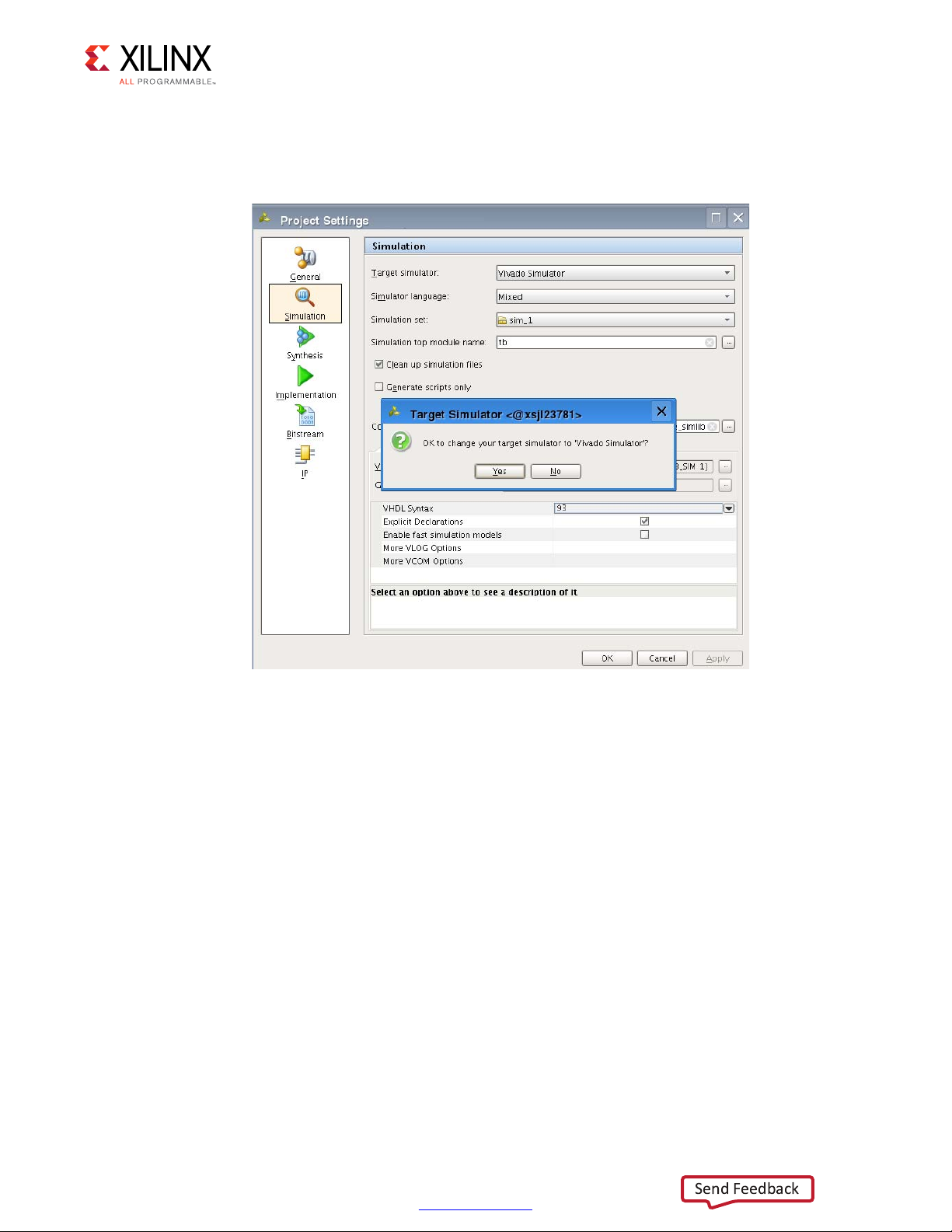
To run a simulation using the Vivado Design Suite Simulator:
1. In the Flow Navigator, under Project Manager, click Settings.
www.xilinx.com
Page 62
Chapter 4: Implementing and Simulating the Design
X18478-120716
Send Feedback
2. In the Project Settings window (Figure 4-17), select Vivado Simulator in the Target
simulator field and click Yes when asked if it is OK to change your target simulator to
Vivado Simulator. click OK in the Project Settings window.
X-Ref Target - Figure 4-17
Figure 4-17: Set Simulator to Vivado Simulator
3. In the Flow Navigator, under Simulation, click Run Simulation > Run Behavioral
Simulation.
10GBASE-KR Ethernet TRD 62
UG1058 (v2017.1) April 19, 2017
www.xilinx.com
Page 63

Reference Design Details
Integrated Blocks in FPGA
Xilinx IP
Custom Logic
On Board
AXI-Lite (Master to Slave)
AXI-Stream
SMA
Line
CARD
SMA
Line
CARD
Backplane
KCU1250 Board
CHANNEL 1
CHANNEL 0
C
C
0
XCKU040-2FFGA1156C FPGA
64 bits
XGMII
64 bits at 156.25MHz
10GBASE -KR
64 bits at 156.25MHz
AXI Interconnect
AXI UART
Lite
MicroBlaze
Subsystem
64 bits
XGMII
10G
MAC
10GBASE -KR
GTH Transceiver
AXI LITE
10G
MAC
AXI LITE
GTH Transceiver
To the
UART
Java GUI/Driver
and Vivado
Design Suite
USB -UART
SiLabs CP2105
Control
Computer
Traffic
Generator
and
Monitor
Traffic
Generator
and
Monitor
USB -JTAG
AXI Interconnect
JTAG to
AXI
MicroBlaze
Subsystem
AXI DRP
Bridge
AXI BRAM
Controller
BRAM
AXI DRP
Bridge
DRP
DRP
Eyescan System
X18479-120716
Send Feedback
This chapter describes the hardware design and software components.
Hardware
Figure 5-1 shows a block-level overview of the 10GBASE-KR TRD.
X-Ref Target - Figure 5-1
Chapter 5
HANNEL 1
Figure 5-1: 10GBASE-KR TRD Block Diagram
HANNEL
10GBASE-KR Ethernet TRD 63
UG1058 (v2017.1) April 19, 2017
www.xilinx.com
Page 64

Chapter 5: Reference Design Details
Send Feedback
The details of the hardware architecture are provided in three sections:
• Data Plane Components: Describes the 10-Gigabit Ethernet PCS/PMA IP core
(10GBASE-KR), 10-Gigabit Ethernet MAC IP core (10G MAC) and the Traffic Generator
and Monitor.
• Control Plane Components: Describes the MicroBlaze™ processor subsystem and the
peripherals connected to it.
• Eye Scan System Components Describes the MicroBlaze processor subsystem and JTAG
to AXI Master IP core that communicate with the DRP port of the transceivers to collect
data samples and create an eye diagram.
• Clocking and Reset: Describes how clocks and resets are distributed to the different
components in the 10GBASE-KR TRD.
Data Plane Components
The 10-Gigabit Ethernet PCS/PMA IP (10GBASE-KR) and 10-Gigabit Ethernet MAC IP (10G
MAC) cores constitute a 10 Gb/s Ethernet channel. There are two channels in the
10GBASE-KR TRD; channel 0 and channel 1. The data source for each channel is a Traffic
Generator implemented in the FPGA that drives the 10G Ethernet MAC.
10-Gigabit Ethernet PCS/PMA IP Core
The 10-Gigabit Ethernet PCS/PMA (10GBASE-KR) IP core provides an XGMII interface to
connect to a 10-Gigabit Ethernet MAC IP core and implements a 10.3125 Gb/s serial
single-channel PHY (GTH transceiver) brought out to TXN/TXP and RXN/RXP I/O pins that
are connected to differential SMA connector pairs on the board. SMA cables connect these
signals to the backplane.
The 10GBASE-KR IP core is configured to support auto negotiation (AN) and forward error
correction (FEC). The MDIO interface is disabled and configuration and status vectors are
used to manage the core.
A license can be obtained at the 10 Gigabit Ethernet PCS/PMA with FEC/Auto-Negotiation
(10GBASE-KR) website [Ref 17]. More information is available in the 10G Ethernet PCS/PMA
LogiCORE IP Product Guide (PG068) [Ref 19].
Relevant bits of the configuration and status vectors are brought out to Virtual
Input/Output (VIO) IP cores to configure and monitor the IP. The training port of the
10-Gigabit Ethernet PCS/PMA is also connected to a VIO IP core to access the transceiver's
DRP address map.
More VIO IP core information is available at the Virtual Input/Output (VIO) website [Ref 20]
and in the Virtual Input/Output LogiCORE IP Product Guide (PG159) [Ref 21]. Details about
the DRP address map is available in UltraScale Architecture GTH Transceivers User Guide
(UG576) [Ref 15].
10GBASE-KR Ethernet TRD 64
UG1058 (v2017.1) April 19, 2017
www.xilinx.com
Page 65

Chapter 5: Reference Design Details
Traffic Generator
AXI4-Stream RX traffic
from the MAC
AXI4-Stream TX traffic to
the MAC
AXI-Lite transactions to
and from the MicroBlaze
Processor Subsystem
PHY status
User Control and Status
Registers
Generator (Internal)
Performance Monitor
X18480-120716
Send Feedback
10-Gigabit Ethernet MAC IP Core
The 10-Gigabit Ethernet MAC (10G MAC) IP core is a single-speed, full-duplex, 10-Gb/s
Ethernet Media Access Controller. This 10G MAC connects to the PHY layer through the
XGMII interface. The internal Traffic Generator drives data on the AXI4-Stream ports of this
IP.
A license can be obtained at the 10 Gigabit Ethernet Media Access Controller (10GEMAC)
website [Ref 16]. More information is available the 10G Ethernet MAC LogiCORE IP Product
Guide (PG072) [Ref 22].
Traffic Generator and Monitor
Figure 5-2 shows the Traffic Generator and Monitor. The traffic generator block generates
Ethernet Traffic. The performance monitor block monitors the AXI4-Stream ports of the
10-Gigabit Ethernet MAC IP core and reports throughput.
The User Control and Status Register block passes information to and from the Ethernet
Controller application using the MicroBlaze processor subsystem.
X-Ref Target - Figure 5-2
Internal Traffic Generator, Generator Module
Figure 5-2: Traffic Generator and Monitor
10GBASE-KR Ethernet TRD 65
UG1058 (v2017.1) April 19, 2017
The internal Traffic Generator module generates Ethernet packets based on user inputs
provided from the Ethernet Controller application running on the control computer. Data
payload size can be from 46 bytes to 1,500 bytes. Table 5-1 shows the packet format
generated by the internal Traffic Generator module.
www.xilinx.com
Page 66

Chapter 5: Reference Design Details
Send Feedback
Table 5-1: Packet Format of Generated Packets
Byte 7Byte 6Byte 5Byte 4Byte 3Byte 2Byte 1Byte 0
Source Address Destination Address
Sequence Number Length Source Address
. . . . . . . . . . . . . . . . . . . . . . . . . . . . . . . . . . . . Sequence Number Sequence Number
Sequence Number . . . . . . . . . . . . . . . . . . . . . . . . . . . . . . . . . . . . . . . . . . . . . . . . . . . . . . . .
The source and destination MAC addresses are parameters into this block. The length field
is the data payload value. The actual length of a packet generated by this block is:
• 14 bytes of header (Destination Address + Source Address + Length/Type Field) +
Data payload
The sequence number field indicates packet count and increments by one every packet.
The generated packets are transmitted on AXI4-Stream interface to the 10-Gigabit Ethernet
MAC IP core. Table 5-2 shows the parameters and ports on the generator module.
Table 5-2: Generator Module Parameters and Ports
Port/Parameter Name Type Description
Source MAC Address
XIL_MAC_ID_THIS Parameter
XIL_MAC_ID_OTHER Parameter
For channel 0 = 48'h111100000000
For channel 1 = 48'h222200000000
Destination MAC Address
For channel 0 = 48'h222200000000
For channel 1 = 48'h111100000000
Clock and Reset Ports
reset Input Synchronous reset.
tx_axis_clk Input 156.25 MHz clock transmit ports on the AXI4-Stream interface.
Transmit Ports on the AXI4-Stream Interface
tx_axis_tdata[63:0] Output Data to be transmitted to the 10-Gigabit Ethernet MAC IP core.
The transmit keep signal is used to determine which data bytes are valid
on tx_axis_tdata during a given beat (this signal is valid only if
tx_axis_tvalid and tx_axis_tready are both asserted).
tx_axis_tkeep[7:0]
Bit 0 corresponds to the least significant byte on tx_axis_tdata and bit 7
corresponds to the most significant byte.
When tx_axis_tlast is not asserted, the only valid value is 0xFF. When
tx_axis_tlast is asserted, valid values are 0x1, 0x3, 0x7, 0xf, 0x1f, 0x3f,
0x7f and 0xff.
tx_axis_tlast Output
tx_axis_tvalid Output
10GBASE-KR Ethernet TRD 66
UG1058 (v2017.1) April 19, 2017
End of frame indicator on transmit packets. Valid only along with assertion
of tx_axis_tvalid.
Source ready to provide transmit data. Indicates that the generator is
presenting valid data on tx_axis_tdata.
www.xilinx.com
Page 67

Chapter 5: Reference Design Details
Send Feedback
Table 5-2: Generator Module Parameters and Ports (Cont’d)
Port/Parameter Name Type Description
tx_axis_tuser Output If asserted indicates an underrun frame. This is tied to 1'b0.
Destination ready for transmit. Indicates that the 10-Gigabit Ethernet
tx_axis_tready Input
MAC IP core is ready to accept data on tx_axis_tdata.
The simultaneous assertion of tx_axis_tvalid and tx_axis_tready marks the
successful transfer of one data beat on tx_axis_tdata.
Control Ports
enable_gen Input Enable internal generator.
data_payload Input Size of the payload (46 bytes to 1,500 Bytes).
The data flow with internal generator mode enabled on the Traffic Generator for channel 0
is:
Generator module CH0 → CH0 TX AXI4-Stream interface of the 10-Gigabit Ethernet
MAC IP → CH0 TX XGMII interface of the 10-Gigabit Ethernet PCS/PMA IP → CH0
TXN/TXP serial lines → loopback to CH1 RXN/RXP serial lines → CH1 RX XGMII
interface of the 10-Gigabit Ethernet PCS/PMA → CH1 RX AXI4-Stream interface of the
10-Gigabit Ethernet MAC IP core
The data flow with internal generator mode enabled on Traffic Generator for channel 1 is:
Generator module CH1 → CH1 TX AXI4-Stream interface of the 10-Gigabit Ethernet
MAC IP → CH1 TX XGMII interface of the 10-Gigabit Ethernet PCS/PMA IP → CH1
TXN/TXP serial lines → loopback to CH0 RXN/RXP serial lines → CH0 RX XGMII
interface of the 10-Gigabit Ethernet PCS/PMA IP → CH0 RX AXI4-Stream interface of the
10-Gigabit Ethernet MAC IP core
Ethernet Performance Monitor
The Ethernet performance monitor block snoops for valid transactions on the AXI4-Stream
interface ports of the 10-Gigabit Ethernet MAC IP core and keeps track of bandwidth
utilization. A timer within this block counts the clocks until one second has elapsed, during
which time counters have collected data about link performance.
Four counters collect information on the transactions on the AXI4-Stream interface:
• TX Payload Byte Count. This counter counts bytes transferred when tx_tvalid and
tx_tready signals are asserted between the Traffic Generator block and the 10G MAC. At
the end of the packet (tx_tlast) 14 bytes of header are subtracted from the count to get
payload count.
• TX Packet Count. This counter counts the number of transmitted packets. The counter
increments when tx_tvalid and tx_tready and tx_tlast signal are asserted.
10GBASE-KR Ethernet TRD 67
UG1058 (v2017.1) April 19, 2017
• RX Payload Byte Count. This counter counts bytes transferred when rx_tvalid and
rx_tready signals are asserted between the Traffic Generator block and the 10G MAC. At
www.xilinx.com
Page 68

Chapter 5: Reference Design Details
Send Feedback
the end of the packet (rx_tlast) 14 bytes of header are subtracted from the count to get
payload count.
• RX Packet Count. This counter counts the number of received packets. The counter
increments when rx_tvalid and rx_tready and rx_tlast signal are asserted.
The counts are truncated to a four-byte resolution, and the last two bits of the register
indicate the sampling period. The last two bits transition every second from 00 to 01 to 10
to 11. The software polls the performance registers every second. If the sampling bits are
the same as the previous read, then the software needs to discard the second read and try
again. When the one-second timer expires, the new byte counts are loaded into the
registers, overwriting the previous values. Table 5-3 shows the parameters and ports on this
module.
Table 5-3: Ethernet Performance Monitor Parameters and Ports
Port/Parameter Name Type Description
ONE_SEC_CLOCK_COUNT Parameter
Defines the number of 156.25 MHz clock cycles equivalent to 1 sec.
Default value is 32'h9502F90.
Clock and Reset Ports
reset Input Synchronous reset.
clk Input 156.25 MHz clock.
Transmit Ports on the AXI4-Stream Interface
tx_axis_tdata[63:0] Input Data to be transmitted to the 10-Gigabit Ethernet MAC IP core.
The transmit keep signal is used to determine which data bytes are valid
on tx_axis_tdata during a given beat (this signal is valid only if
tx_axis_tvalid and tx_axis_tready are both asserted).
tx_axis_tkeep[7:0]
tx_axis_tlast Input
tx_axis_tvalid Input
tx_axis_tuser Input If asserted indicates an underrun frame. This is tied to 1'b0.
Bit 0 corresponds to the least significant byte on tx_axis_tdata and bit 7
corresponds to the most significant byte. When tx_axis_tlast is not
asserted, the only valid value is 0xFF.
When tx_axis_tlast is asserted, valid values are 0x01, 0x03, 0x07, 0x0F,
0x1F, 0x3F,0x7F, and 0xFF.
End of frame indicator on transmit packets. Valid only along with
assertion of tx_axis_tvalid.
Source ready to provide transmit data. Indicates that the generator is
presenting valid data on tx_axis_tdata.
tx_axis_tready Input
Receive Ports on the AXI4-Stream Interface
rx_axis_tdata[63:0] Input Data received by the 10-Gigabit Ethernet MAC IP core.
10GBASE-KR Ethernet TRD 68
UG1058 (v2017.1) April 19, 2017
Destination ready for transmit. Indicates that the 10-Gigabit Ethernet
MAC IP core is ready to accept data on tx_axis_tdata.
The simultaneous assertion of tx_axis_tvalid and tx_axis_tready marks the
successful transfer of one data beat on tx_axis_tdata.
www.xilinx.com
Page 69

Chapter 5: Reference Design Details
AXI4-Lite to IPIF
AXI-4 Lite transactions
to and from the
MicroBlaze Processor
Status: Performance, PHY
status, etc.
Control: Internal traffic generator
selection, payload size, etc.
Status and Control
Register Map
X18481-120716
Send Feedback
Table 5-3: Ethernet Performance Monitor Parameters and Ports (Cont’d)
Port/Parameter Name Type Description
The receive keep signal is used to determine which data bytes are valid
rx_axis_tkeep[7:0]
on rx_axis_tdata during a given beat (this signal is valid only if
tx_axis_tvalid and tx_axis_tready are both asserted).
rx_axis_tlast Input
rx_axis_tvalid Input
rx_axis_tuser Input If asserted indicates a good packet is received.
rx_axis_tready Output
End of frame indicator on received packets. Valid only along with
asser-tion of rx_axis_tvalid.
Source ready to provide data. Indicates that the MAC is presenting valid
data on rx_axis_tdata.
Destination ready for receive. Indicates that the loopback is ready to
accept data on rx_axis_tdata.
The simultaneous assertion of rx_axis_tvalid and rx_axis_tready marks
the successful transfer of one data beat on rx_axis_tdata.
The 10-Gigabit Ethernet MAC IP core doesn't look at this signal and
sends received data whenever available.
Performance Statistics Ports
tx_byte_count Output Number of bytes transmitted in one second.
tx_pkt_count Output Number of packets transmitted in one second.
rx_byte_count Output Number of bytes received in one second.
rx_pkt_count Output Number of packets received in one second.
User Control and Status Registers
The user selections made in the Ethernet controller application are passed to the Traffic
Generator and Monitor using this block. An AXI4-Lite interface is required for the
MicroBlaze processor subsystem to execute reads (status) and writes (control) to this block.
The AXI4-Lite IP Interface (IPIF) is instantiated in the design to read and write to a register
map file (see the AXI4-Lite IP Interface (IPIF)
website [Ref 23].
X-Ref Target - Figure 5-3
10GBASE-KR Ethernet TRD 69
UG1058 (v2017.1) April 19, 2017
Providing an AXI4-Lite slave interface provides the flexibility of using this module in other
designs. To reuse this block, the control and status signals into the register map must be
changed. Appendix C, User-Space Registers describes the registers implemented in the
Traffic Generator and Monitor block. Figure 5-3 shows the user register interface.
Figure 5-3: User Register Interface
www.xilinx.com
Page 70

Chapter 5: Reference Design Details
X18482-120716
Send Feedback
Control Plane Components
The Ethernet Controller application running on the control computer sends control
information and receives status to and from different components of the 10GBASE-KR TRD
using the MicroBlaze processor subsystem.
MicroBlaze Processor Subsystem and AXI Interconnect
The IP cores required to support the MicroBlaze processor and create a subsystem are:
• MicroBlaze local memory
• Processor system reset
• MicroBlaze debug module
• AXI Interrupt controller
In Vivado IPI, adding the MicroBlaze IP core and running the connection automation creates
the MicroBlaze processor system shown in Figure 5-4.
X-Ref Target - Figure 5-4
Figure 5-4: IPI-Generated MicroBlaze Processor System
The AXI interconnect IP allows the MicroBlaze processor subsystem to communicate with
the AXI Interrupt controller IP using the AXI4 memory mapped interface.
10GBASE-KR Ethernet TRD 70
UG1058 (v2017.1) April 19, 2017
The 10GBASE-KR TRD AXI interconnect IP is reconfigured to have six master ports instead
of one. The six master ports connect to six AXI slaves:
• AXI interrupt controller
www.xilinx.com
Page 71

X-Ref Target - Figure 5-5
X18483-120716
Send Feedback
Chapter 5: Reference Design Details
• AXI UART Lite which communicates with the Ethernet Controller application running on
the control computer
• Channel 0 – 10-Gigabit Ethernet MAC IP core
• The Traffic Generator and Monitor connected to channel 0
• Channel 1 – 10-Gigabit Ethernet MAC IP core
• The Traffic Generator and Monitor connected to channel 1
The AXI interconnect enables communication between the MicroBlaze processor subsystem
(Master) and six peripherals (Slaves).
The address range assigned to each peripheral is shown in Figure 5-5. The application
driver running on the MicroBlaze processor subsystem will use these addresses to map
read/write transactions from the Ethernet Controller application to the AXI UART Lite to the
MicroBlaze processor subsystem to other peripherals and back.
Figure 5-5: Peripheral Address Map
For more details on the MicroBlaze processor core, see the MicroBlaze Soft Processor Core
website [Ref 24].
For more details on AXI Interconnect, see the AXI Interconnect website [Ref 25].
AXI UART Lite
The AXI UART Lite IP core provides the controller interface for asynchronous serial data
transfer. The Ethernet Controller application running on the control computer
communicates with this serial interface.
The AXI UART Lite IP core also connects to the MicroBlaze processor subsystem through the
AXI interface and passes information to and from the Ethernet Controller application to the
different components of the design.
For more details on AXI UART Lite, see AXI UART Lite LogiCORE IP Product Guide (PG142)
[Ref 26] and the AXI UART Lite website [Ref 27].
10GBASE-KR Ethernet TRD 71
UG1058 (v2017.1) April 19, 2017
www.xilinx.com
Page 72

Chapter 5: Reference Design Details
Send Feedback
Eye Scan System Components
The eye scan system in this reference design is based on application note XAPP1198. Refer
to In-System Eye Scan of a PCI Express Link with Vivado IP Integrator and AXI4 Application
Note (XAPP1198) [Ref 14] for more information.
AXI DRP Bridge
The AXI DRP bridge receives AXI requests from an AXI master such as the MicroBlaze
processor subsystem. It converts AXI transactions to DRP registers accesses on the
transceiver and routes the result back to the AXI Master. One bridge is required for every
transceiver that performs an eye scan. This reference design has two instances of the AXI
DRP bridge to get eye scan plots on 10-Gigabit Ethernet Channel 0 and Channel 1.
There is also an AXI DRP MUX in the reference design. This allows multiplexing of DRP
accesses between the AXI DRP Bridge and the 10-Gigabit Ethernet PCS/PMA IP Core.
AXI Block RAM Controller
An AXI Slave IP core that allows access to local block RAM by AXI Master devices such as
MicroBlaze processor subsystem and JTAG to AXI Master IP core. The block RAM stores the
data read from the DRP port of the transceiver.
For more details on the AXI Block RAM Controller IP, see the AXI BRAM Controller website
[Ref 28].
JTAG to AXI Master
The JTAG to AXI Master IP core is a customizable core that can generate AXI transactions
and drive AXI signals internal to FPGA. The Vivado logic analyzer Tcl console running on the
control computer interacts with this core through the USB-to-JTAG port on the
KCU1250 board. (Refer to Vivado Design Suite User Guide: Programming and Debugging
(UG908) [Ref 29].) It retrieves data stored in AXI BRAM Controller and passes it to the
control computer.
For more details on the JTAG to AXI Master IP core, see the JTAG to AXI Master website
[Ref 30].
MicroBlaze Processor Subsystem
The MicroBlaze processor subsystem communicates to the transceiver DRP interface
through the AXI to DRP Bridge logic. The software running on the MicroBlaze processor is
derived from code described in Eye Scan with MicroBlaze Processor MCS Application Note
(XAPP743) [Ref 31]. The software running on the processor implements the Eye Scan
algorithm on the transceiver and stores the data in the AXI block RAM. When the block RAM
is filled with Eye Scan data, the JTAG to AXI IP core reads the data out of the block RAM.
10GBASE-KR Ethernet TRD 72
UG1058 (v2017.1) April 19, 2017
www.xilinx.com
Page 73

X-Ref Target - Figure 5-6
X18484-120716
Send Feedback
Chapter 5: Reference Design Details
Then it stores the data on the control computer in a text file through the USB-JTAG
connection (U80) on the KCU1250 board.
For more details on the MicroBlaze processor core, see the MicroBlaze Soft Processor Core
website [Ref 24].
AXI Interconnect
The AXI interconnect allows multiple AXI masters (MicroBlaze processor subsystem and
JTAG to AXI Master) to communicate with multiple AXI slaves (AXI DRP Bridge and AXI
BRAM Controller). The address map for the AXI slaves is shown in Figure 5-6.
Figure 5-6: AXI Slaves Address Map in the Eye Scan System
For more details on the AXI Interconnect, see the AXI Interconnect website [Ref 25].
Clocking and Reset
The 10-Gigabit Ethernet PCS/PMA core requires a 156.25 MHz differential reference clock
for the GTH transceivers. The shared logic (clocking and reset logic) within the channel 0
10-Gigabit Ethernet PCS/PMA IP core produces a single ended 156.25 MHz clock. This clock
is used by the 10-Gigabit Ethernet MAC and Traffic generator on Channel 0. A similar clock
circuit is implemented for Channel 1. The MicroBlaze processor subsystem is driven by the
10GBASE-KR Ethernet TRD 73
UG1058 (v2017.1) April 19, 2017
www.xilinx.com
Page 74

X-Ref Target - Figure 5-7
CH1 MAC
CH1 PHY
CH0 PHY
CH0 Traffic
Gen-Mon
CH0 MAC
s_axi_clk
CH1
Traffic
Gen-Mon
AXI
UARTLITE
MicroBlaze
Subsytem and
AXI Interconnect
s_axi_clk
s_axi_clk
s_axi_clk
s_axi_clk
156.25 MHz
156.25 MHz
Differential Clock
156.25 MHz
Differential Clock
156.25 MHz CH0 156.25 MHz CH1
Eyescan
System
X18485-120716
Send Feedback
Chapter 5: Reference Design Details
channel 0 156.25 MHz clock. The single ended 156.25 MHz clocks from both channels are
routed to the eye scan system. Figure 5-7 shows the clock distribution.
Figure 5-7: Clock Distribution
An external reset (a debounced DIP switch) drives the channel 0 10-Gigabit Ethernet
PCS/PMA IP core, the 10-Gigabit Ethernet MAC IP core and the Processor System Reset IP
core in the processor system. This reset also drives the eye scan system.
Another external reset dip switch drives the Channel 1 10-Gigabit Ethernet PCS/PMA IP
core, the 10-Gigabit Ethernet MAC IP core and the Traffic Generator and Monitor block.
10GBASE-KR Ethernet TRD 74
UG1058 (v2017.1) April 19, 2017
www.xilinx.com
Page 75

X-Ref Target - Figure 5-8
CH0
PHY
CH0
MAC
CH0
Traffic
Gen-Mon
CH1
PHY
CH1
Traffic
Gen-Mon
CH1
MAC
reset ch0
reset_ch0_n
Processor
System
Reset
peripheral_aresetn
AXI UART
Lite
AXI
Interrupt
Controller
AXI
Interconnect
interconnect_aresetn
MicroBlaze
Processor
mb_reset
MicroBlaze
Local
memory
bus_struct_reset
Debouncer
Logic
DIP Switch
Reset
s_axi_aresetn
s_axi_aresetn
axis_aresetn
axis_aresetn
axis_aresetn
axis_aresetn
ext_rst
s_axis_aresetns_axis_areset
n
s_axis_aresetn
s_axi_aresetn
Reset to AXI4 Stream Interface
Reset to MAC and PHY
Reset to AXI Lite Interfaces
reset ch1
Debouncer
Logic
DIP Switch
Reset
reset_ch1_n
Eyescan
System
X18486-120716
Send Feedback
Chapter 5: Reference Design Details
The Processor System Reset Module IP core provides resets for the MicroBlaze processor
subsystem components and resets to the AXI Interconnect and peripherals (AXI4-Lite
interfaces on AXI UART Lite, Traffic Generator and Monitor, and 10-Gigabit Ethernet MAC
IP). Figure 5-8 shows the reset connections.
Figure 5-8: Resets
10GBASE-KR Ethernet TRD 75
UG1058 (v2017.1) April 19, 2017
www.xilinx.com
Page 76

Chapter 5: Reference Design Details
Microblaze Processor on KCU1250 Board
Server Application
Control Computer
GUI/Client Application
UART Interface
X18487-120716
Send Feedback
Software
There are two major software components to monitor and control the Ethernet Reference
Design System:
• GUI/Client Application
• MicroBlaze Processor Server Application
Figure 5-9 shows these components.
X-Ref Target - Figure 5-9if
Figure 5-9: Software Components
GUI/Client Application
A Java-based GUI/Client application running on the control computer communicates with
the MicroBlaze Processor Server Application through a UART interface to control test
parameters, collect statistics, and display current status of the design.
The GUI displays the following information:
• Current mode of operation
•Payload size
• Throughput numbers and graphs when a test is executing
• 10-Gigabit Ethernet MAC IP statistics
• Power consumption and temperature for the FPGA
• Block diagram of the design
10GBASE-KR Ethernet TRD 76
UG1058 (v2017.1) April 19, 2017
www.xilinx.com
Page 77

Figure 5-10 shows the GUI.
X18488-120716
Send Feedback
X-Ref Target - Figure 5-10
Chapter 5: Reference Design Details
Figure 5-10: GUI (Ethernet Controller Application)
The GUI provides control of:
• Test mode: Select use of the internal traffic generator to generate Ethernet traffic.
• Payload size: Specify the size of packets when running in internal generator mode.
The GUI interacts with the KCU1250 board through the UART COM port exposed by the
Silicon Labs UART driver. All transmitted and received data adheres to a custom command
model followed by the client and server.
Command Format
The command format used by the GUI for reading and writing 32-bit values to the registers
in the design is described in this section.
Read Command
R <type of request> <output type> <Command number, denoted as a
4-character hexadecimal numeric string, AAAA>
• R denotes a Read command
10GBASE-KR Ethernet TRD 77
UG1058 (v2017.1) April 19, 2017
www.xilinx.com
Page 78

Chapter 5: Reference Design Details
Send Feedback
• type of request indicates the type of request and it can either be:
s which specifies a single register read request, or
°
b which specifies a bulk read request
°
Use a single register read for debugging purposes or for reading registers which are not
monitored by the GUI.
Use a bulk read command to make the GUI constantly poll all test parameters and statistics.
This eliminates the need to send multiple commands for each individual value. A bulk read
command reads the registers in a predefined order.
• output type indicates output type and it can be:
h specifies the value sent out by the server will be the actual data width i.e., 4 bytes
°
a specifies the value sent out by the server will be an 8-byte hexadecimal string
°
• AAAA denotes four character hexadecimal numeric string representation of the
command number which will eventually be mapped to the actual register offset in the
server application. Using different command numbers instead of the actual register
values allows the GUI to remain constant in spite of changes in the hardware design or
the application.
Example Read command:
R s a 0001: Read a single register corresponding to command number 0001 and the
reported value from the server should be in 8-byte hexadecimal format.
Read command response:
1. The command number is read by the server and the appropriate register is identified, its
value is read, and is stored in a 4-byte data value.
2. Based on the output type specified in the read command, the data is either directly
transmitted to the client by the server, or it is converted to an 8-character string
denoting an 8-character hexadecimal number and then sent out to the client on the
control computer side.
Currently the application only supports output type of 8-character hexadecimal string.
An example Read command output response: F000000F.
Write Command
W <Command Number denoted as a 4-character hexadecimal numeric string
AAAA> < Data, represented as an 8-character hexadecimal numeric
string DDDDDDDD>
10GBASE-KR Ethernet TRD 78
UG1058 (v2017.1) April 19, 2017
• W denotes a Write command
www.xilinx.com
Page 79

Chapter 5: Reference Design Details
Executer
Command
Interpreter
UART Driver
Register Offset
Identification for the Executer
Form Response
and Send to Client on Host Side
Command Number
to Array Index Mapping
--
1
2
3
4
5
6
7
8
9
10
--
Integer Array
Containing All
Register Offsets
X18489-120716
Send Feedback
• AAAA denotes a 4-character hexadecimal string representation of the command
number which will eventually be mapped to the actual register offset in the server
application.
• DDDDDDDD denotes an 8-character hexadecimal string.
Example Write command:
• W 0001 007D0002: Write a value of 007D0002 to the register corresponding to
command value 0001.
Write command is always targeted towards a single register.
The mapping of command numbers to the corresponding register values is the same for
both Read and Write commands, i.e., if a write command with a certain command number
is used to update a register value, the same command number can be used with a read
command to retrieve the value.
MicroBlaze Processor Server Application
MicroBlaze Processor Server application running on the FPGA takes care of interpreting the
read and write commands sent from the client application, and acts accordingly. The
software layers are as shown in Figure 5-11.
X-Ref Target - Figure 5-11
Figure 5-11: Software Layers in the MicroBlaze Processor Server Application
10GBASE-KR Ethernet TRD 79
UG1058 (v2017.1) April 19, 2017
www.xilinx.com
Page 80

Chapter 5: Reference Design Details
Send Feedback
When the hardware platform is exported to the Software Development Kit (SDK) as
described in Generate ELF File for the MicroBlaze Controller in mac_phy.bd:
• The drivers for standard peripherals (like UART, Interrupt controller, etc.) that are
connected to the MicroBlaze processor are already available in the SDK.
• The base address of each peripheral assigned in the hardware platform as shown in
Figure 5-5 and is also accessible by the SDK.
The register offsets required by the server application to access relevant registers (TRD
configuration registers, performance registers, MAC Statistics, etc.) are available in the 10G
Ethernet MAC LogiCORE IP Product Guide (PG072) [Ref 22] and the user space registers as
described in
Appendix C, User-Space Registers.
The UART driver is responsible for transferring and receiving data from the UART interface.
The server application uses the Application Programming Interface (API) provided by the
UART driver and communicates with the client application running on the control computer.
The main task of the server is to read/write values from/to the registers specified in the
READ/WRITE commands issued by the GUI.
The various steps undertaken by the server in servicing requests from the client are:
1. Register offsets to access registers are put in an integer array during the initialization of
MicroBlaze processor server application. The value placed in the integer array is:
Base address for the component + register offset
°
2. The order in which these register offset values are placed is made aware to the client
application on the host side.
3. Each register is identified using a unique command number. This command number is
same for both read and write commands.
4. When a client initiates a Read/Write command, the data is obtained by the server
application through the UART driver.
5. The Command Interpreter part of the server application then interprets the data
obtained from UART.
6. The Command Interpreter identifies the register offset value in the integer array, with
respect to the command number associated with the request.
7. The Command Interpreter functionality is different for Single Read and Bulk Read
commands.
10GBASE-KR Ethernet TRD 80
UG1058 (v2017.1) April 19, 2017
www.xilinx.com
Page 81

Chapter 5: Reference Design Details
Send Feedback
8. For a single read request, command number shall give the index of the integer array
where the referenced register offset is placed.
Example Single Read Command:
R s a 0001
Here the command number is translated to 1 and the offset value of the register being
requested is placed in the zero index of the array.
9. For a bulk read request the command number represents a set of registers with a clearly
defined start and end index positions in the array.
Example Bulk Read Command:
R b a 0001
Here the command number 1 represents a set of register offsets in the array, 2 to 17. The
values placed at these array indexes are the Ethernet performance registers for Channel
0 and Channel 1.
10. The Executor part of the server application then initiates either AXI Read/Write request
to the register offset values identified.
11. The Executor then sends an appropriate response to the client on control computer
through the UART driver.
NOTE: The bulk Read commands from GUI are serviced by the Server application by going through all
the registers associated with the command in a predefined order and transferring the data with a ' '
(white space) as delimiter between each register's value. This mode greatly reduces the number of
commands the GUI has to send to obtain the same amount of information.
The source code for the MicroBlaze application is available under the software/source
directory (see Appendix A, Directory Structure). The command mapping is defined in
CommandDesc.h.
NOTE: The software components for generating eye scans are described in Eye Scan with MicroBlaze
Processor MCS Application Note (XAPP743)
Vivado IP Integrator and AXI4 Application Note (XAPP1198)
document.
[Ref 31] and In-System Eye Scan of a PCI Express Link with
[Ref 14] and are not covered in this
10GBASE-KR Ethernet TRD 81
UG1058 (v2017.1) April 19, 2017
www.xilinx.com
Page 82

Directory Structure
scripts
uc1250_10gbasekr_trd
ready_to_test
source
GUI
software
hdl
sources
hardware
ip_packaged
ip
constraints
testbench
vivado
readme
X18425-120716
Send Feedback
The directory structures for the 10GBASE-KR TRD is shown in Figure A-1.
X-Ref Target - Figure A-1
Appendix A
Figure A-1: Targeted Reference Design Directory Structure
10GBASE-KR Ethernet TRD 82
UG1058 (v2017.1) April 19, 2017
www.xilinx.com
Page 83

Appendix A: Directory Structure
Send Feedback
Directory Content Summary
The files and folders contained in the 10GBASE-KR TRD are described in Table A-1. The
top-level folder is kcu1250_10gbasekr_trd.
Table A-1: Directory Content
Folder Description
software Contains the software design deliverables.
source Contains the source code files used for creating the ELF file application that runs
on the MicroBlaze™ processor and communicates with the GUI.
GUI Contains the EXE file used to install the Ethernet Controller GUI.
hardware Contains all the required sources needed to generate a bitstream.
sources Contains subfolders that contain HDL files, custom IP that is packaged, VIO IP files,
constraint files, and test bench files.
hdl Contains HDL files.
ip_packaged Contains custom IP that is packaged.
ip Contains VIO IP files.
constraints Contains constraint files.
testbench Contains test bench files.
vivado Contains files to create a Vivado® Design Suite project and outputs of vivado runs.
scripts Contains Tcl scripts to create a Vivado project.
runs Created when the Tcl script file is sourced. The runs folder contains the output of
simulation, synthesis and implementation processes.
ready_to_test Contains the bit file to program the KCU1250 characterization board.
readme A TXT file that describes the 10GBASE-KR TRD and includes revision history
information.
10GBASE-KR Ethernet TRD 83
UG1058 (v2017.1) April 19, 2017
www.xilinx.com
Page 84

Performance Estimates
Send Feedback
The 10-Gigabit Ethernet MAC IP core operates at a clock rate of 156.25 MHz using a 64-bit
data-path width (64 x 156.25 x 10
For the XGMII, the minimum required interframe gap is 12 bytes. Header overhead consists
of a preamble (7 bytes) + Start of frame delimiter (1 byte) + MAC destination address (6
bytes) + MAC source address (6 bytes) + Length/Type field (2 bytes) + FCS (4 bytes). This
gives a total overhead of 38 bytes per Ethernet packet.
Table B-1 shows the effective throughput and percentage of maximum bandwidth used for
four different payload sizes.
Table B-1: Effective Throughput as a Function of Payload
6
=10Gb/s).
Appendix B
Ethernet Payload Size
(Bytes)
64 64/(38 + 64) = 62.7% 6.27
512 512/(38 + 512) = 93.1% 9.31
1024 1024/(38 + 1024) = 96.3% 9.63
1500 1500/(38 + 1500) = 97.5% 9.75
Percentage of Bandwidth =
Payload size/Packet size * 100
Effective Throughput
(Gb/s)
10GBASE-KR Ethernet TRD 84
UG1058 (v2017.1) April 19, 2017
www.xilinx.com
Page 85

User-Space Registers
Send Feedback
User space registers are user-defined registers implemented in the Traffic Generator and
Monitor block shown in Figure 5-1. These registers can be accessed by the MicroBlaze™
processor subsystem via the AXI4-Lite interface.
Table C-1 through Table C-14 describe the custom registers implemented in the
10GBASE-KR TRD. All registers are 32 bits wide. Register bit positions are to be read from bit
31 to bit 0 from left to right. All bits that are undefined in this section are reserved and will
return zero when read. Address holes will also return a value of zero when read.
Each peripheral connected to the MicroBlaze processor subsystem is assigned an offset
address which is the base address for that peripheral. Figure 5-5 shows the addresses
assigned to the Traffic Generator and Monitor blocks (eth_axi_stream_gen_mon_0 and
eth_axi_stream_gen_mon_1). The Traffic Generator and Monitor base addresses are:
Appendix C
• Traffic Generator and Monitor channel 0: 0x4AA0_0000
• Traffic Generator and Monitor channel 1: 0x4AA1_0000
Control and Status Registers
Traffic Generator—Monitor Channel 0
Table C-1: Design Version Register (0x4AA0_0000)
Bit Position Mode Default Value Description
3:0
15:4 12’h141
31:16 16’h1250 Target Board: KCU1250 board.
Read Only
4’h2 Ethernet reference design 2.
Indicates the Vivado® Design Suite version used when
developing this reference design. For example, Vivado Design
Suite 2014.1 is indicated by 141.
10GBASE-KR Ethernet TRD 85
UG1058 (v2017.1) April 19, 2017
www.xilinx.com
Page 86

Appendix C: User-Space Registers
Send Feedback
Table C-2: Ethernet Performance Monitor, Transmit Payload Byte Count Register (0x4AA0_0004)
Bit Position Mode Default Value Description
1:0
Read Only
31:2 0
00 Sample count. Increments once every second.
Transmit payload byte count. This field contains the interface
utilization count for active beats (tx_axis_tready = 1 and
tx_axis_tvalid = 1) on channel 0 10G Ethernet MAC AXI4-Stream
interface for transmit.
Table C-3: Ethernet Performance Monitor, Transmit Packet Count Register (0x4AA0_0008)
Bit Position Mode Default Value Description
1:0
Read Only
31:2 0
00 Sample count. Increments once every second.
Transmit packet count. This field contains the count for the
event when there is an active beat on channel 0 10G Ethernet
MAC AXI4-Stream interface and end of packet (tx_axis_tlast) is
asserted for transmit.
Table C-4: Ethernet Performance Monitor, Received Payload Byte Count Register (0x4AA0_000C)
Bit Position Mode Default Value Description
1:0
Read Only
31:2 0
00 Sample count. Increments once every second.
Receive payload byte count. This field contains the interface
utilization count for active beats (rx_axis_tready = 1 and
rx_axis_tvalid = 1) on channel 0 10G Ethernet MAC AXI4-Stream
interface for receive.
Table C-5: Ethernet Performance Monitor, Received Packet Count Register (0x4AA0_0010)
Bit Position Mode Default Value Description
1:0
Read Only
31:2 0
00 Sample count. Increments once every second.
Receive packet count. This field contains the count for the event
when there is an active beat on channel 0 10G Ethernet MAC
AXI4-Stream interface and end of packet (rx_axis_tlast) is
asserted for receive.
Table C-6: Traffic Generator Configuration Register (0x4AA0_0014)
Bit Position Mode Default Value Description
0
1 0 Enable generator if internal generator is selected.
31:16 d'125
Read or Write
0 Reserved.
Ethernet frame data payload size. Allowed values (46 bytes to
1,500 bytes).
Table C-7: PHY status Register (0x4AA0_00x18)
Bit Position Mode Default Value Description
0Read Only0 PHY is up.
10GBASE-KR Ethernet TRD 86
UG1058 (v2017.1) April 19, 2017
www.xilinx.com
Page 87

Appendix C: User-Space Registers
Send Feedback
Traffic Generator—Monitor Channel 1
Table C-8: Design Version Register (0x4AA1_0000)
Bit Position Mode Default Value Description
4:0
14:5 12’h141
31:16 16’h1250 Target Board. KCU1250 board.
Read Only
4’h2 Ethernet reference design 2.
Software version: Indicates the Vivado® Design Suite version
used when developing this reference design. For example,
Vivado Design Suite 2014.1 is indicated by 141.
Table C-9: Ethernet Performance Monitor, Transmit Payload Byte Count Register (0x4AA1_0004)
Bit Position Mode Default Value Description
1:0
Read Only
31:2 0
00 Sample count. Increments once every second.
Transmit payload byte count. This field contains the interface
utilization count for active beats (tx_axis_tready = 1 and
tx_axis_tvalid = 1) on channel 1 10G Ethernet MAC AXI4-Stream
interface for transmit.
Table C-10: Ethernet Performance Monitor, Transmit Packet Count Register (0x4AA1_0008)
Bit Position Mode Default Value Description
1:0
Read Only
31:2 0
00 Sample count. Increments once every second.
Transmit packet count. This field contains the count for the
event when there is an active beat on channel 1 10G Ethernet
MAC AXI4-Stream interface and end of packet (tx_axis_tlast) is
asserted for transmit.
Table C-11: Ethernet Performance Monitor, Received Payload Byte Count Register (0x4AA1_000C)
Bit Position Mode Default Value Description
1:0
Read Only
31:2 0
00 Sample count. Increments once every second.
Receive payload byte count. This field contains the interface
utilization count for active beats (rx_axis_tready = 1 and
rx_axis_tvalid = 1) on channel 1 - 10G Ethernet MAC
AXI4-Stream interface for receive.
Table C-12: Ethernet Performance Monitor, Received Packet Count Register (0x4AA1_0010)
Bit Position Mode Default Value Description
1:0
Read Only
31:2 0
00 Sample count. Increments once every second.
Receive packet count. This field contains the count for the event
when there is an active beat on channel 1 10G Ethernet MAC
AXI4-Stream interface and end of packet (rx_axis_tlast) is
asserted for receive.
10GBASE-KR Ethernet TRD 87
UG1058 (v2017.1) April 19, 2017
www.xilinx.com
Page 88

Appendix C: User-Space Registers
Send Feedback
Table C-13: Traffic Generator Configuration Register (0x4AA1_0014)
Bit Position Mode Default Value Description
0
1 0 Enable generator if internal generator is selected.
31:16 d'125
Read or Write
0 Reserved.
Ethernet frame. Data payload size allowed values = 46 bytes to
1,500 bytes.
Table C-14: status Register (0x4AA1_00x18)
Bit Position Mode Default Value Description
0 Read Only 0 PHY is up.
10GBASE-KR Ethernet TRD 88
UG1058 (v2017.1) April 19, 2017
www.xilinx.com
Page 89

Appendix D
Send Feedback
Additional Resources and Legal Notices
Xilinx Resources
For support resources such as Answers, Documentation, Downloads, and Forums, see Xilinx
Support.
Solution Centers
See the Xilinx Solution Centers for support on devices, software tools, and intellectual
property at all stages of the design cycle. Topics include design assistance, advisories, and
troubleshooting tips.
References
The most up-to-date information for this design is available on these websites:
KCU1250 Characterization Kit
KCU1250 Characterization Kit Documentation
KCU1250 Characterization Kit Master Answer Record (AR 63058)
These documents and sites provide supplemental material:
1. IEEE Std 802.3-2012
IEEE Standard for Ethernet (includes specifications for 10GBASE-KR and 10GBASE-R)
CU1250 Characterization Kit website
2. K
3. Tyco Electronics
Z-Pack TINMAN Customer System Kit User’s Guide (backplane)
4. Samtec Bulls Eye cables
5. Aeroflex/Inmet
website
website
website: SMA DC Blocks
10GBASE-KR Ethernet TRD 89
UG1058 (v2017.1) April 19, 2017
www.xilinx.com
Page 90

Appendix D: Additional Resources and Legal Notices
Send Feedback
6. Silicon Labs CP210x USB to UART Bridge VCP Drivers
7. Tera Term Home Page
8. Vivado Design Suite User Guide Release Notes, Installation, and Licensing (UG973
9. Silicon Labs CP210x USB-to-UART Installation Guide (UG1033
10. Tera Term Terminal Emulator Installation Guide (UG1036
11. Oracle
12. KCU1250 Characterization Board Schematics (XTP398
13. HW-CLK-101-SCLK2 SuperClock-2 Module User Guide (UG770
14. In-System Eye Scan of a PCI Express Link with Vivado IP Integrator and AXI4 Application
Note (XAPP1198
15. UltraScale Architecture GTH Transceivers User Guide (UG576
10 Gigabit Ethernet Media Access Controller (10GEMAC) website
16.
17. 10 Gigabit Ethernet PCS/PMA with FEC/Auto-Negotiation (10GBASE-KR)
18. Vivado Design Suite User Guide: Logic Simulation (UG900)
19. 10G Ethernet PCS/PMA LogiCORE IP Product Guide (PG068)
20. Virtual Input/Output (VIO)
Java SE Runtime Environment 7
: Tera Term Pro terminal emulator software
)
)
)
)
)
)
)
website
website
21. Virtual Input/Output LogiCORE IP Product Guide (PG159
22. 10G Ethernet MAC LogiCORE IP Product Guide (PG072
AXI4-Lite IP Interface (IPIF) website
23.
icroBlaze Soft Processor Core website
24. M
25. AXI Interconnect
26. AXI UART Lite LogiCORE IP Product Guide (PG142
27. AXI UART Lite
XI BRAM Controller website
28. A
29. Vivado Design Suite User Guide: Programming and Debugging (UG908
30. JTAG to AXI Master
31. Eye Scan with MicroBlaze Processor MCS Application Note (XAPP743
32. UltraScale Architecture System Monitor User Guide (UG580
33. AXI4-Lite IPIF LogiCORE IP Product Guide (PG155
34. System Management Wizard LogiCORE IP Product Guide (PG185
website
)
website
website
)
)
)
)
)
)
)
10GBASE-KR Ethernet TRD 90
UG1058 (v2017.1) April 19, 2017
www.xilinx.com
Page 91

Appendix D: Additional Resources and Legal Notices
Send Feedback
Training Resources
35. Vivado Design Suite Hands-on Introductory Workshop
36. Vivado Design Suite Tool Flow
Please Read: Important Legal Notices
The information disclosed to you hereunder (the “Materials”) is provided solely for the selection and use of Xilinx products. To the
maximum extent permitted by applicable law: (1) Materials are made available "AS IS" and with all faults, Xilinx hereby DISCLAIMS
ALL WARRANTIES AND CONDITIONS, EXPRESS, IMPLIED, OR STATUTORY, INCLUDING BUT NOT LIMITED TO WARRANTIES OF
MERCHANTABILITY, NON-INFRINGEMENT, OR FITNESS FOR ANY PARTICULAR PURPOSE; and (2) Xilinx shall not be liable (whether
in contract or tort, including negligence, or under any other theory of liability) for any lo ss or damag e o f any kind o r nature related
to, arising under, or in connection with, the Materials (including your use of the Materials), including for any direct, indirect, special,
incidental, or consequential loss or damage (including loss of data, profits, goodwill, or any type of loss or damage suffered as a
result of any action brought by a third party) even if such damage or loss was reasonably foreseeable or Xilinx had been advised
of the possibility of the same. Xilinx assumes no obligation to correct any errors contained in the Materials or to notify you of
updates to the Materials or to product specifications. You may not reproduce, modify, distribute, or publicly display the Materials
without prior written consent. Certain products are subject to the terms and conditions of Xilinx’s limited warranty, please refer to
Xilinx’s Terms of Sale which can be viewed at https://www.xilinx.com/legal.htm#tos
support terms contained in a license issued to you by Xilinx. Xilinx products are not designed or intended to be fail-safe or for use
in any application requiring fail-safe performance; you assume sole risk and liability for use of Xilinx products in such critical
applications, please refer to Xilinx’s Terms of Sale which can be viewed at https://www.xilinx.com/legal.htm#tos
AUTOMOTIVE APPLICATIONS DISCLAIMER
AUTOMOTIVE PRODUCTS (IDENTIFIED AS “XA” IN THE PART NUMBER) ARE NOT WARRANTED FOR USE IN THE DEPLOYMENT OF
AIRBAGS OR FOR USE IN APPLICATIONS THAT AFFECT CONTROL OF A VEHICLE (“SAFETY APPLICATION”) UNLESS THERE IS A
SAFETY CONCEPT OR REDUNDANCY FEATURE CONSISTENT WITH THE ISO 26262 AUTOMOTIVE SAFETY STANDARD (“SAFETY
DESIGN”). CUSTOMER SHALL, PRIOR TO USING OR DISTRIBUTING ANY SYSTEMS THAT INCORPORATE PRODUCTS, THOROUGHLY
TEST SUCH SYSTEMS FOR SAFETY PURPOSES. USE OF PRODUCTS IN A SAFETY APPLICATION WITHOUT A SAFETY DESIGN IS FULLY
AT THE RISK OF CUSTOMER, SUBJECT ONLY TO APPLICABLE LAWS AND REGULATIONS GOVERNING LIMITATIONS ON PRODUCT
LIABILITY.
© Copyright 2014–2017 Xilinx, Inc. Xilinx, the Xilinx logo, Artix, ISE, Kintex, Spartan, Virtex, Vivado, Zynq, and other designated
brands included herein are trademarks of Xilinx in the United States and other countries. All other trademarks are the property of
their respective owners.
; IP cores may be subject to warranty and
.
10GBASE-KR Ethernet TRD 91
UG1058 (v2017.1) April 19, 2017
www.xilinx.com
 Loading...