


1000BASE-X
Table of contents
 Loading...
LogiCORE™ IP
Ethernet 1000BASE-X
PCS/PMA or SGMII v9.1
User Guide
UG155 March 24, 2008
R
R
Xilinx is disclosing this Specification to you solely for use in the development of designs to operate on Xilinx FPGAs. Except as stated herein,
none of the Specification may be copied, reproduced, distributed, republished, downloaded, displayed, posted, or transmitted in any form or
by any means including, but not limited to, electronic, mechanical, photocopying, recording, or otherwise, without the prior written consent
of Xilinx. Any unauthorized use of this Specification may violate copyright laws, trademark laws, the laws of privacy and publicity, and
communications regulations and statutes.
Xilinx does not assume any liability arising out of the application or use of the Specification; nor does Xilinx convey any license under its
patents, copyrights, or any rights of others. You are responsible for obtaining any rights you may require for your use or implementation of
the Specification. Xilinx reserves the right to make changes, at any time, to the Specification as deemed desirable in the sole discretion of
Xilinx. Xilinx assumes no obligation to correct any errors contained herein or to advise you of any correction if such be made. Xilinx will not
assume any liability for the accuracy or correctness of any engineering or technical support or assistance provided to you in connection with
the Specification.
THE SPECIFICATION IS PROVIDED “AS IS" WITH ALL FAULTS, AND THE ENTIRE RISK AS TO ITS FUNCTION AND
IMPLEMENTATION IS WITH YOU. YOU ACKNOWLEDGE AND AGREE THAT YOU HAVE NOT RELIED ON ANY ORAL OR WRITTEN
INFORMATION OR ADVICE, WHETHER GIVEN BY XILINX, OR ITS AGENTS OR EMPLOYEES. XILINX MAKES NO OTHER
WARRANTIES, WHETHER EXPRESS, IMPLIED, OR STATUTORY, REGARDING THE SPECIFICATION, INCLUDING ANY
WARRANTIES OF MERCHANTABILITY, FITNESS FOR A PARTICULAR PURPOSE, TITLE, AND NONINFRINGEMENT OF THIRDPARTY RIGHTS.
IN NO EVENT WILL XILINX BE LIABLE FOR ANY CONSEQUENTIAL, INDIRECT, EXEMPLARY, SPECIAL, OR INCIDENTAL DAMAGES,
INCLUDING ANY LOST DATA AND LOST PROFITS, ARISING FROM OR RELATING TO YOUR USE OF THE SPECIFICATION, EVEN IF
YOU HAVE BEEN ADVISED OF THE POSSIBILITY OF SUCH DAMAGES. THE TOTAL CUMULATIVE LIABILITY OF XILINX IN
CONNECTION WITH YOUR USE OF THE SPECIFICATION, WHETHER IN CONTRACT OR TORT OR OTHERWISE, WILL IN NO EVENT
EXCEED THE AMOUNT OF FEES PAID BY YOU TO XILINX HEREUNDER FOR USE OF THE SPECIFICATION. YOU ACKNOWLEDGE
THAT THE FEES, IF ANY, REFLECT THE ALLOCATION OF RISK SET FORTH IN THIS AGREEMENT AND THAT XILINX WOULD NOT
MAKE AVAILABLE THE SPECIFICATION TO YOU WITHOUT THESE LIMITATIONS OF LIABILITY.
The Specification is not designed or intended for use in the development of on-line control equipment in hazardous environments requiring
fail-safe controls, such as in the operation of nuclear facilities, aircraft navigation or communications systems, air traffic control, life support,
or weapons systems (“High-Risk Applications”). Xilinx specifically disclaims any express or implied warranties of fitness for such High-Risk
Applications. You represent that use of the Specification in such High-Risk Applications is fully at your risk.
© 2004-2007 Xilinx, Inc. All rights reserved. XILINX, the Xilinx logo, and other designated brands included herein are trademarks of Xilinx,
Inc. All other trademarks are the property of their respective owners.
Revision History
The following table shows the revision history for this document.
Date
09/30/04 1.0 Initial Xilinx release.
04/28/05 2.0 Updated to Xilinx tools 7.1i SP2, support for Virtex-4 Rocket IO.
01/18/06 3.0 Updated to Xilinx tools 8.1i SP1 for 7.0 release, added new chapter for dynamic switching.
07/13/06 4.0 Updated to core version 7.1; Xilinx tools 8.2i.
10/23/06 5.0 Updated to core version 8.0, support for Virtex-5 LXT and Spartan-3A families.
02/15/07 6.0 Updated to core version 8.1, Xilinx tools 9.1i.
08/08/07 7.0 Updated to core version 9.0, Xilinx tools 9.2i.
03/24/08 8.0 Updated to core version 9.1, Xilinx tools 10.1.
Doc
Version
Revision
www.xilinx.com Ethernet 1000BASE-X PCS/PMA or SGMII v9.1
UG155 March 24, 2008

Table of Contents
Schedule of Figures. . . . . . . . . . . . . . . . . . . . . . . . . . . . . . . . . . . . . . . . . . . . . . . . . . . . . . . . . . 9
Schedule of Tables . . . . . . . . . . . . . . . . . . . . . . . . . . . . . . . . . . . . . . . . . . . . . . . . . . . . . . . . . . 13
Preface: About This Guide
Guide Contents. . . . . . . . . . . . . . . . . . . . . . . . . . . . . . . . . . . . . . . . . . . . . . . . . . . . . . . . . . . . . . . . . . . . . 17
Conventions . . . . . . . . . . . . . . . . . . . . . . . . . . . . . . . . . . . . . . . . . . . . . . . . . . . . . . . . . . . . . . . . . . . . . . . . 18
Typographical. . . . . . . . . . . . . . . . . . . . . . . . . . . . . . . . . . . . . . . . . . . . . . . . . . . . . . . . . . . . 18
Online Document . . . . . . . . . . . . . . . . . . . . . . . . . . . . . . . . . . . . . . . . . . . . . . . . . . . . . . . . . 19
Chapter 1: Introduction
About the Core . . . . . . . . . . . . . . . . . . . . . . . . . . . . . . . . . . . . . . . . . . . . . . . . . . . . . . . . . . . . . . . . . . . . . 21
Designs Using RocketIO Transceivers . . . . . . . . . . . . . . . . . . . . . . . . . . . . . . . . . . . . . . . 21
Recommended Design Experience . . . . . . . . . . . . . . . . . . . . . . . . . . . . . . . . . . . . . . . . . . . . . . . . 21
Additional Core Resources . . . . . . . . . . . . . . . . . . . . . . . . . . . . . . . . . . . . . . . . . . . . . . . . . . . . . . . . 21
Related Xilinx Ethernet Products and Services . . . . . . . . . . . . . . . . . . . . . . . . . . . . . . . . 22
Specifications . . . . . . . . . . . . . . . . . . . . . . . . . . . . . . . . . . . . . . . . . . . . . . . . . . . . . . . . . . . . 22
Technical Support. . . . . . . . . . . . . . . . . . . . . . . . . . . . . . . . . . . . . . . . . . . . . . . . . . . . . . . . . . . . . . . . . . 22
Feedback. . . . . . . . . . . . . . . . . . . . . . . . . . . . . . . . . . . . . . . . . . . . . . . . . . . . . . . . . . . . . . . . . . . . . . . . . . . . 22
Ethernet 1000BASE-X PCS/PMA or SGMII Core . . . . . . . . . . . . . . . . . . . . . . . . . . . . . . 22
Document . . . . . . . . . . . . . . . . . . . . . . . . . . . . . . . . . . . . . . . . . . . . . . . . . . . . . . . . . . . . . . . 22
Chapter 2: Core Architecture
System Overview. . . . . . . . . . . . . . . . . . . . . . . . . . . . . . . . . . . . . . . . . . . . . . . . . . . . . . . . . . . . . . . . . . . 23
Ethernet 1000BASE-X PCS/PMA or SGMII Using A RocketIO Transceiver . . . . . . . 23
Ethernet 1000BASE-X PCS/PMA or SGMII with Ten-Bit-Interface . . . . . . . . . . . . . . . 25
Core Interfaces . . . . . . . . . . . . . . . . . . . . . . . . . . . . . . . . . . . . . . . . . . . . . . . . . . . . . . . . . . . . . . . . . . . . . 26
Client Side Interface. . . . . . . . . . . . . . . . . . . . . . . . . . . . . . . . . . . . . . . . . . . . . . . . . . . . . . . 31
Physical Side Interface. . . . . . . . . . . . . . . . . . . . . . . . . . . . . . . . . . . . . . . . . . . . . . . . . . . . . 36
Chapter 3: Generating and Customizing the Core
GUI Interface . . . . . . . . . . . . . . . . . . . . . . . . . . . . . . . . . . . . . . . . . . . . . . . . . . . . . . . . . . . . . . . . . . . . . . . 39
Component Name . . . . . . . . . . . . . . . . . . . . . . . . . . . . . . . . . . . . . . . . . . . . . . . . . . . . . . . . 39
Select Standard . . . . . . . . . . . . . . . . . . . . . . . . . . . . . . . . . . . . . . . . . . . . . . . . . . . . . . . . . . . 40
Core Functionality . . . . . . . . . . . . . . . . . . . . . . . . . . . . . . . . . . . . . . . . . . . . . . . . . . . . . . . . 40
SGMII/Dynamic Standard Switching Elastic Buffer Options. . . . . . . . . . . . . . . . . . . . 41
RocketIO Tile Configuration . . . . . . . . . . . . . . . . . . . . . . . . . . . . . . . . . . . . . . . . . . . . . . . 43
Parameter Values in the XCO File. . . . . . . . . . . . . . . . . . . . . . . . . . . . . . . . . . . . . . . . . . . . . . . . . 43
Output Generation . . . . . . . . . . . . . . . . . . . . . . . . . . . . . . . . . . . . . . . . . . . . . . . . . . . . . . . . . . . . . . . . . 44
Chapter 4: Designing with the Core
Design Overview. . . . . . . . . . . . . . . . . . . . . . . . . . . . . . . . . . . . . . . . . . . . . . . . . . . . . . . . . . . . . . . . . . . 45
Design Guidelines . . . . . . . . . . . . . . . . . . . . . . . . . . . . . . . . . . . . . . . . . . . . . . . . . . . . . . . . . . . . . . . . . 50
Generate the Core . . . . . . . . . . . . . . . . . . . . . . . . . . . . . . . . . . . . . . . . . . . . . . . . . . . . . . . . 50
Examine the Example Design Provided with the Core . . . . . . . . . . . . . . . . . . . . . . . . . 50
Ethernet 1000BASE-X PCS/PMA or SGMII v9.1 www.xilinx.com
UG155 March 24, 2008

R
Implement the Ethernet 1000BASE-X PCS/PMA or SGMII Core
in Your Application . . . . . . . . . . . . . . . . . . . . . . . . . . . . . . . . . . . . . . . . . . . . . . . . . . . . . 50
Chapter 5: Using the Client-side GMII Data Path
Designing with the Client-side GMII for the 1000BASE-X Standard. . . . . . . . . . . . 53
GMII Transmission . . . . . . . . . . . . . . . . . . . . . . . . . . . . . . . . . . . . . . . . . . . . . . . . . . . . . . . 53
GMII Reception . . . . . . . . . . . . . . . . . . . . . . . . . . . . . . . . . . . . . . . . . . . . . . . . . . . . . . . . . . 54
status_vector[4:0] signals . . . . . . . . . . . . . . . . . . . . . . . . . . . . . . . . . . . . . . . . . . . . . . . . . . 56
Using the Virtex-II Pro RocketIO Transceiver CRC Functionality . . . . . . . . . . . . . . . . 57
Designing with Client-side GMII for the SGMII Standard. . . . . . . . . . . . . . . . . . . . . . 59
Overview . . . . . . . . . . . . . . . . . . . . . . . . . . . . . . . . . . . . . . . . . . . . . . . . . . . . . . . . . . . . . . . . 59
GMII Transmission . . . . . . . . . . . . . . . . . . . . . . . . . . . . . . . . . . . . . . . . . . . . . . . . . . . . . . . 59
GMII Reception . . . . . . . . . . . . . . . . . . . . . . . . . . . . . . . . . . . . . . . . . . . . . . . . . . . . . . . . . . 60
Using the GMII as an Internal Connection . . . . . . . . . . . . . . . . . . . . . . . . . . . . . . . . . . . . . . . 61
Implementing External GMII . . . . . . . . . . . . . . . . . . . . . . . . . . . . . . . . . . . . . . . . . . . . . . . . . . . . . 61
GMII Transmitter Logic . . . . . . . . . . . . . . . . . . . . . . . . . . . . . . . . . . . . . . . . . . . . . . . . . . . 61
GMII Receiver Logic . . . . . . . . . . . . . . . . . . . . . . . . . . . . . . . . . . . . . . . . . . . . . . . . . . . . . . 66
Chapter 6: The Ten-Bit Interface
Ten-Bit-Interface Logic . . . . . . . . . . . . . . . . . . . . . . . . . . . . . . . . . . . . . . . . . . . . . . . . . . . . . . . . . . . . 69
Transmitter Logic . . . . . . . . . . . . . . . . . . . . . . . . . . . . . . . . . . . . . . . . . . . . . . . . . . . . . . . . . 69
Receiver Logic. . . . . . . . . . . . . . . . . . . . . . . . . . . . . . . . . . . . . . . . . . . . . . . . . . . . . . . . . . . . 70
Clock Sharing across Multiple Cores with TBI . . . . . . . . . . . . . . . . . . . . . . . . . . . . . . . . . . . 77
Chapter 7: 1000BASE-X with RocketIO Transceivers
RocketIO Transceiver Logic . . . . . . . . . . . . . . . . . . . . . . . . . . . . . . . . . . . . . . . . . . . . . . . . . . . . . . . 79
Virtex-II Pro Devices . . . . . . . . . . . . . . . . . . . . . . . . . . . . . . . . . . . . . . . . . . . . . . . . . . . . . . 79
Virtex-4 FX Devices . . . . . . . . . . . . . . . . . . . . . . . . . . . . . . . . . . . . . . . . . . . . . . . . . . . . . . . 81
Virtex-5 LXT and SXT Devices . . . . . . . . . . . . . . . . . . . . . . . . . . . . . . . . . . . . . . . . . . . . . . 83
Virtex-5 FXT Devices . . . . . . . . . . . . . . . . . . . . . . . . . . . . . . . . . . . . . . . . . . . . . . . . . . . . . . 85
Clock Sharing Across Multiple Cores with RocketIO. . . . . . . . . . . . . . . . . . . . . . . . . . . . 87
Virtex-II Pro Devices . . . . . . . . . . . . . . . . . . . . . . . . . . . . . . . . . . . . . . . . . . . . . . . . . . . . . . 87
Virtex-4 FX Devices . . . . . . . . . . . . . . . . . . . . . . . . . . . . . . . . . . . . . . . . . . . . . . . . . . . . . . . 88
Virtex-5 LXT and SXT Devices . . . . . . . . . . . . . . . . . . . . . . . . . . . . . . . . . . . . . . . . . . . . . . 90
Virtex-5 FXT Devices . . . . . . . . . . . . . . . . . . . . . . . . . . . . . . . . . . . . . . . . . . . . . . . . . . . . . . 92
Chapter 8: SGMII / Dynamic Standards Switching with RocketIO
Transceivers
Receiver Elastic Buffer Implementations . . . . . . . . . . . . . . . . . . . . . . . . . . . . . . . . . . . . . . . . . 95
Selecting the Buffer Implementation from the GUI . . . . . . . . . . . . . . . . . . . . . . . . . . . . 95
The Requirement for the FPGA Fabric Rx Elastic Buffer . . . . . . . . . . . . . . . . . . . . . . . . 96
The RocketIO Rx Elastic Buffer . . . . . . . . . . . . . . . . . . . . . . . . . . . . . . . . . . . . . . . . . . . . . 97
RocketIO Logic using the RocketIO Rx Elastic Buffer . . . . . . . . . . . . . . . . . . . . . . . . . . . 98
RocketIO Logic with the Fabric Rx Elastic Buffer . . . . . . . . . . . . . . . . . . . . . . . . . . . . . . . . 98
Virtex-II Pro Devices . . . . . . . . . . . . . . . . . . . . . . . . . . . . . . . . . . . . . . . . . . . . . . . . . . . . . . 98
Virtex-4 Devices for SGMII or Dynamic Standards Switching . . . . . . . . . . . . . . . . . . 101
Virtex-5 LXT or SXT Devices for SGMII or Dynamic Standards Switching . . . . . . . 103
Virtex-5 FXT Devices for SGMII or Dynamic Standards Switching . . . . . . . . . . . . . . 105
Clock Sharing - Multiple Cores with RocketIO, Fabric Elastic Buffer . . . . . . . . . 107
Virtex-II Pro Devices . . . . . . . . . . . . . . . . . . . . . . . . . . . . . . . . . . . . . . . . . . . . . . . . . . . . . 107
Virtex-4 FX Devices . . . . . . . . . . . . . . . . . . . . . . . . . . . . . . . . . . . . . . . . . . . . . . . . . . . . . . 109
www.xilinx.com Ethernet 1000BASE-X PCS/PMA or SGMII v9.1
UG155 March 24, 2008

Virtex-5 LXT and SXT Devices . . . . . . . . . . . . . . . . . . . . . . . . . . . . . . . . . . . . . . . . . . . . . 111
Virtex-5 FXT Devices . . . . . . . . . . . . . . . . . . . . . . . . . . . . . . . . . . . . . . . . . . . . . . . . . . . . . 113
Chapter 9: Configuration and Status
MDIO Management Interface . . . . . . . . . . . . . . . . . . . . . . . . . . . . . . . . . . . . . . . . . . . . . . . . . . . . 115
MDIO Bus System . . . . . . . . . . . . . . . . . . . . . . . . . . . . . . . . . . . . . . . . . . . . . . . . . . . . . . . 115
MDIO Transactions . . . . . . . . . . . . . . . . . . . . . . . . . . . . . . . . . . . . . . . . . . . . . . . . . . . . . . 116
MDIO Addressing . . . . . . . . . . . . . . . . . . . . . . . . . . . . . . . . . . . . . . . . . . . . . . . . . . . . . . . 117
Connecting the MDIO to an Internally Integrated STA . . . . . . . . . . . . . . . . . . . . . . . . 118
Connecting the MDIO to an External STA . . . . . . . . . . . . . . . . . . . . . . . . . . . . . . . . . . . 118
Management Registers. . . . . . . . . . . . . . . . . . . . . . . . . . . . . . . . . . . . . . . . . . . . . . . . . . . . . . . . . . . . 119
1000BASE-X Standard Using the Optional Auto-Negotiation . . . . . . . . . . . . . . . . . . 119
1000BASE-X Standard Without the Optional Auto-Negotiation . . . . . . . . . . . . . . . . 129
SGMII Standard Using the Optional Auto-Negotiation. . . . . . . . . . . . . . . . . . . . . . . . 135
SGMII Standard without the Optional Auto-Negotiation . . . . . . . . . . . . . . . . . . . . . . 145
Both 1000BASE-X and SGMII Standards . . . . . . . . . . . . . . . . . . . . . . . . . . . . . . . . . . . . 150
Optional Configuration Vector . . . . . . . . . . . . . . . . . . . . . . . . . . . . . . . . . . . . . . . . . . . . . . . . . . . 151
Chapter 10: Auto-Negotiation
Overview of Operation . . . . . . . . . . . . . . . . . . . . . . . . . . . . . . . . . . . . . . . . . . . . . . . . . . . . . . . . . . . 153
1000BASE-X Standard . . . . . . . . . . . . . . . . . . . . . . . . . . . . . . . . . . . . . . . . . . . . . . . . . . . . 153
SGMII Standard . . . . . . . . . . . . . . . . . . . . . . . . . . . . . . . . . . . . . . . . . . . . . . . . . . . . . . . . . 155
Setting the Configurable Link Timer . . . . . . . . . . . . . . . . . . . . . . . . . . . . . . . . . . . . . . . . . . . . 156
1000BASE-X Standard . . . . . . . . . . . . . . . . . . . . . . . . . . . . . . . . . . . . . . . . . . . . . . . . . . . . 156
SGMII Standard . . . . . . . . . . . . . . . . . . . . . . . . . . . . . . . . . . . . . . . . . . . . . . . . . . . . . . . . . 156
Simulating Auto-Negotiation . . . . . . . . . . . . . . . . . . . . . . . . . . . . . . . . . . . . . . . . . . . . . . 156
Using the Auto-Negotiation Interrupt . . . . . . . . . . . . . . . . . . . . . . . . . . . . . . . . . . . . . . . . . . . 156
R
Chapter 11: Dynamic Switching of 1000BASE-X and SGMII Standards
Typical Application . . . . . . . . . . . . . . . . . . . . . . . . . . . . . . . . . . . . . . . . . . . . . . . . . . . . . . . . . . . . . . . 157
Operation of the Core . . . . . . . . . . . . . . . . . . . . . . . . . . . . . . . . . . . . . . . . . . . . . . . . . . . . . . . . . . . . . 158
Selecting the Power-On / Reset Standard . . . . . . . . . . . . . . . . . . . . . . . . . . . . . . . . . . . 158
Switching the Standard Using MDIO . . . . . . . . . . . . . . . . . . . . . . . . . . . . . . . . . . . . . . . 158
Auto-Negotiation State Machine . . . . . . . . . . . . . . . . . . . . . . . . . . . . . . . . . . . . . . . . . . . 158
Setting the Auto-Negotiation Link Timer . . . . . . . . . . . . . . . . . . . . . . . . . . . . . . . . . . . 158
Chapter 12: Constraining the Core
Required Constraints . . . . . . . . . . . . . . . . . . . . . . . . . . . . . . . . . . . . . . . . . . . . . . . . . . . . . . . . . . . . . 161
Device, Package, and Speedgrade Selection . . . . . . . . . . . . . . . . . . . . . . . . . . . . . . . . . 161
I/O Location Constraints . . . . . . . . . . . . . . . . . . . . . . . . . . . . . . . . . . . . . . . . . . . . . . . . . 161
Placement Constraints . . . . . . . . . . . . . . . . . . . . . . . . . . . . . . . . . . . . . . . . . . . . . . . . . . . . 161
Virtex-II Pro RocketIO MGTs for 1000BASE-X Constraints . . . . . . . . . . . . . . . . . . . . 161
Virtex-II Pro RocketIO MGTs for SGMII or Dynamic Standards
Switching Constraints . . . . . . . . . . . . . . . . . . . . . . . . . . . . . . . . . . . . . . . . . . . . . . . . . . 163
Virtex-4 RocketIO MGTs for 1000BASE-X Constraints . . . . . . . . . . . . . . . . . . . . . . . . 164
Virtex-4 RocketIO MGTs for SGMII or Dynamic Standards Switching Constraints 166
Virtex-5 RocketIO GTP Transceivers for 1000BASE-X Constraints . . . . . . . . . . . . . . 166
Virtex-5 RocketIO GTP Transceivers for SGMII or Dynamic Standards
Switching Constraints . . . . . . . . . . . . . . . . . . . . . . . . . . . . . . . . . . . . . . . . . . . . . . . . . . 167
Virtex-5 RocketIO GTX Transceivers for 1000BASE-X Constraints . . . . . . . . . . . . . . 167
Ethernet 1000BASE-X PCS/PMA or SGMII v9.1 www.xilinx.com
UG155 March 24, 2008

R
Virtex-5 RocketIO GTX Transceivers for SGMII or Dynamic Standards
Switching Constraints . . . . . . . . . . . . . . . . . . . . . . . . . . . . . . . . . . . . . . . . . . . . . . . . . . 168
Ten-Bit Interface Constraints . . . . . . . . . . . . . . . . . . . . . . . . . . . . . . . . . . . . . . . . . . . . . . 168
Constraints When Implementing an External GMII. . . . . . . . . . . . . . . . . . . . . . . . . . . 172
Understanding Timing Reports for Setup/Hold Timing . . . . . . . . . . . . . . . . . . . . . . 176
Chapter 13: Interfacing to Other Cores
Integrating with the 1-Gigabit Ethernet MAC Core . . . . . . . . . . . . . . . . . . . . . . . . . . . . . 179
Integration of the 1-Gigabit Ethernet MAC to 1000BASE-X PCS with TBI . . . . . . . . 179
Integration of the 1-Gigabit Ethernet MAC Using a RocketIO Transceiver . . . . . . . 181
Integration of the 1-Gigabit Ethernet MAC to Provide SGMII
(or Dynamic Switching) Functionality . . . . . . . . . . . . . . . . . . . . . . . . . . . . . . . . . . . . 185
Integrating with the Tri-Mode Ethernet MAC Core . . . . . . . . . . . . . . . . . . . . . . . . . . . . . 185
Integration of the Tri-Mode Ethernet MAC to Provide SGMII
(or Dynamic Switching) Functionality with TBI . . . . . . . . . . . . . . . . . . . . . . . . . . . . 185
Integration of the Tri-Mode Ethernet MAC to Provide SGMII
(or Dynamic Switching) Functionality using RocketIO Transceivers . . . . . . . . . . 188
Chapter 14: Special Design Considerations
Power Management . . . . . . . . . . . . . . . . . . . . . . . . . . . . . . . . . . . . . . . . . . . . . . . . . . . . . . . . . . . . . . . 197
Startup Sequencing . . . . . . . . . . . . . . . . . . . . . . . . . . . . . . . . . . . . . . . . . . . . . . . . . . . . . . . . . . . . . . . 197
Loopback . . . . . . . . . . . . . . . . . . . . . . . . . . . . . . . . . . . . . . . . . . . . . . . . . . . . . . . . . . . . . . . . . . . . . . . . . . 197
Core with the TBI . . . . . . . . . . . . . . . . . . . . . . . . . . . . . . . . . . . . . . . . . . . . . . . . . . . . . . . . 197
Core with RocketIO Transceiver . . . . . . . . . . . . . . . . . . . . . . . . . . . . . . . . . . . . . . . . . . . 198
Chapter 15: Implementing the Design
Pre-implementation Simulation . . . . . . . . . . . . . . . . . . . . . . . . . . . . . . . . . . . . . . . . . . . . . . . . . . 201
Using the Simulation Model. . . . . . . . . . . . . . . . . . . . . . . . . . . . . . . . . . . . . . . . . . . . . . . 201
Synthesis . . . . . . . . . . . . . . . . . . . . . . . . . . . . . . . . . . . . . . . . . . . . . . . . . . . . . . . . . . . . . . . . . . . . . . . . . . 201
XST - VHDL . . . . . . . . . . . . . . . . . . . . . . . . . . . . . . . . . . . . . . . . . . . . . . . . . . . . . . . . . . . . 201
XST - Verilog . . . . . . . . . . . . . . . . . . . . . . . . . . . . . . . . . . . . . . . . . . . . . . . . . . . . . . . . . . . . 202
Implementation . . . . . . . . . . . . . . . . . . . . . . . . . . . . . . . . . . . . . . . . . . . . . . . . . . . . . . . . . . . . . . . . . . . 202
Generating the Xilinx Netlist . . . . . . . . . . . . . . . . . . . . . . . . . . . . . . . . . . . . . . . . . . . . . . 202
Mapping the Design . . . . . . . . . . . . . . . . . . . . . . . . . . . . . . . . . . . . . . . . . . . . . . . . . . . . . 202
Placing and Routing the Design . . . . . . . . . . . . . . . . . . . . . . . . . . . . . . . . . . . . . . . . . . . 202
Static Timing Analysis. . . . . . . . . . . . . . . . . . . . . . . . . . . . . . . . . . . . . . . . . . . . . . . . . . . . 203
Generating a Bitstream . . . . . . . . . . . . . . . . . . . . . . . . . . . . . . . . . . . . . . . . . . . . . . . . . . . 203
Post-Implementation Simulation. . . . . . . . . . . . . . . . . . . . . . . . . . . . . . . . . . . . . . . . . . . . . . . . . 203
Generating a Simulation Model . . . . . . . . . . . . . . . . . . . . . . . . . . . . . . . . . . . . . . . . . . . . 203
Using the Model . . . . . . . . . . . . . . . . . . . . . . . . . . . . . . . . . . . . . . . . . . . . . . . . . . . . . . . . . 203
Other Implementation Information . . . . . . . . . . . . . . . . . . . . . . . . . . . . . . . . . . . . . . . . . . . . . . 204
Appendix A: Core Verification, Compliance, and Interoperability
Verification . . . . . . . . . . . . . . . . . . . . . . . . . . . . . . . . . . . . . . . . . . . . . . . . . . . . . . . . . . . . . . . . . . . . . . . . 205
Simulation . . . . . . . . . . . . . . . . . . . . . . . . . . . . . . . . . . . . . . . . . . . . . . . . . . . . . . . . . . . . . . . . . . . . . . . . . 205
Hardware Verification . . . . . . . . . . . . . . . . . . . . . . . . . . . . . . . . . . . . . . . . . . . . . . . . . . . . . . . . . . . . 205
www.xilinx.com Ethernet 1000BASE-X PCS/PMA or SGMII v9.1
UG155 March 24, 2008

Appendix B: Core Latency
Core Latency. . . . . . . . . . . . . . . . . . . . . . . . . . . . . . . . . . . . . . . . . . . . . . . . . . . . . . . . . . . . . . . . . . . . . . . 207
Latency for 1000BASE-X PCS with TBI. . . . . . . . . . . . . . . . . . . . . . . . . . . . . . . . . . . . . . 207
Latency for 1000BASE-X PCS and PMA Using a RocketIO Transceiver . . . . . . . . . . 208
Latency for SGMII . . . . . . . . . . . . . . . . . . . . . . . . . . . . . . . . . . . . . . . . . . . . . . . . . . . . . . . 208
Appendix C: Calculating the DCM Fixed Phase Shift Value
Requirement for DCM Phase Shifting . . . . . . . . . . . . . . . . . . . . . . . . . . . . . . . . . . . . . . . . . . . 209
Finding the Ideal Phase Shift Value for Your System . . . . . . . . . . . . . . . . . . . . . . . . . . . 209
Appendix D: 1000BASE-X State Machines
Introduction . . . . . . . . . . . . . . . . . . . . . . . . . . . . . . . . . . . . . . . . . . . . . . . . . . . . . . . . . . . . . . . . . . . . . . . 211
Start of Frame Encoding . . . . . . . . . . . . . . . . . . . . . . . . . . . . . . . . . . . . . . . . . . . . . . . . . . . . . . . . . . 212
The Even Transmission Case . . . . . . . . . . . . . . . . . . . . . . . . . . . . . . . . . . . . . . . . . . . . . . 212
Reception of the Even Case . . . . . . . . . . . . . . . . . . . . . . . . . . . . . . . . . . . . . . . . . . . . . . . 213
The Odd Transmission Case. . . . . . . . . . . . . . . . . . . . . . . . . . . . . . . . . . . . . . . . . . . . . . . 213
Reception of the Odd Case . . . . . . . . . . . . . . . . . . . . . . . . . . . . . . . . . . . . . . . . . . . . . . . . 214
Preamble Shrinkage . . . . . . . . . . . . . . . . . . . . . . . . . . . . . . . . . . . . . . . . . . . . . . . . . . . . . . 215
End of Frame Encoding . . . . . . . . . . . . . . . . . . . . . . . . . . . . . . . . . . . . . . . . . . . . . . . . . . . . . . . . . . . 215
The Even Transmission case. . . . . . . . . . . . . . . . . . . . . . . . . . . . . . . . . . . . . . . . . . . . . . . 215
Reception of the Even Case . . . . . . . . . . . . . . . . . . . . . . . . . . . . . . . . . . . . . . . . . . . . . . . 216
The Odd Transmission Case. . . . . . . . . . . . . . . . . . . . . . . . . . . . . . . . . . . . . . . . . . . . . . . 216
Reception of the Odd Case . . . . . . . . . . . . . . . . . . . . . . . . . . . . . . . . . . . . . . . . . . . . . . . . 217
R
Appendix E: Rx Elastic Buffer Specifications
Introduction . . . . . . . . . . . . . . . . . . . . . . . . . . . . . . . . . . . . . . . . . . . . . . . . . . . . . . . . . . . . . . . . . . . . . . . 219
Rx Elastic Buffers: Depths and Maximum Frame Sizes . . . . . . . . . . . . . . . . . . . . . . . . . 219
RocketIO Rx Elastic Buffers . . . . . . . . . . . . . . . . . . . . . . . . . . . . . . . . . . . . . . . . . . . . . . . 219
SGMII Fabric Rx Elastic Buffer. . . . . . . . . . . . . . . . . . . . . . . . . . . . . . . . . . . . . . . . . . . . . 222
TBI Rx Elastic Buffer . . . . . . . . . . . . . . . . . . . . . . . . . . . . . . . . . . . . . . . . . . . . . . . . . . . . . 223
Clock Correction . . . . . . . . . . . . . . . . . . . . . . . . . . . . . . . . . . . . . . . . . . . . . . . . . . . . . . . . . . . . . . . . . . 224
Maximum Frame Sizes for Sustained Frame Reception. . . . . . . . . . . . . . . . . . . . . . . . . 226
Jumbo Frame Reception . . . . . . . . . . . . . . . . . . . . . . . . . . . . . . . . . . . . . . . . . . . . . . . . . . . . . . . . . . 226
Appendix F: Debugging Guide
General Checks. . . . . . . . . . . . . . . . . . . . . . . . . . . . . . . . . . . . . . . . . . . . . . . . . . . . . . . . . . . . . . . . . . . . 227
Problems with the MDIO. . . . . . . . . . . . . . . . . . . . . . . . . . . . . . . . . . . . . . . . . . . . . . . . . . . . . . . . . 227
Problems with Data Reception or Transmission . . . . . . . . . . . . . . . . . . . . . . . . . . . . . . . . 227
Problems with Auto-Negotiation. . . . . . . . . . . . . . . . . . . . . . . . . . . . . . . . . . . . . . . . . . . . . . . . . 228
Problems in Obtaining a Link (Auto-Negotiation Disabled) . . . . . . . . . . . . . . . . . . . 228
Problems with a High Bit Error Rate . . . . . . . . . . . . . . . . . . . . . . . . . . . . . . . . . . . . . . . . . . . . . 229
Symptoms . . . . . . . . . . . . . . . . . . . . . . . . . . . . . . . . . . . . . . . . . . . . . . . . . . . . . . . . . . . . . . 229
Debugging . . . . . . . . . . . . . . . . . . . . . . . . . . . . . . . . . . . . . . . . . . . . . . . . . . . . . . . . . . . . . . 229
Ethernet 1000BASE-X PCS/PMA or SGMII v9.1 www.xilinx.com
UG155 March 24, 2008

R
www.xilinx.com Ethernet 1000BASE-X PCS/PMA or SGMII v9.1
UG155 March 24, 2008

Schedule of Figures
Chapter 2: Core Architecture
Figure 2-1: Functional Block Diagram Using RocketIO Transceiver . . . . . . . . . . . . . . . . . . . . . . . . . . 24
Figure 2-2: Functional Block Diagram with a Ten-Bit Interface . . . . . . . . . . . . . . . . . . . . . . . . . . . . . . 25
Figure 2-3: Component Pinout Using RocketIO Transceiver
with PCS Management Registers . . . . . . . . . . . . . . . . . . . . . . . . . . . . . . . . . . . . . . . . . . . . . . . . . . . . . . 27
Figure 2-4: Component Pinout Using RocketIO Transceiver
without PCS Management Registers . . . . . . . . . . . . . . . . . . . . . . . . . . . . . . . . . . . . . . . . . . . . . . . . . . . 28
Figure 2-5: Component Pinout Using the Ten-Bit Interface
with PCS Management Registers . . . . . . . . . . . . . . . . . . . . . . . . . . . . . . . . . . . . . . . . . . . . . . . . . . . . . . 29
Figure 2-6: Component Pinout Using Ten-Bit Interface
without PCS Management Registers . . . . . . . . . . . . . . . . . . . . . . . . . . . . . . . . . . . . . . . . . . . . . . . . . . . 30
Figure 2-7: Component Pinout with the Dynamic Switching Logic. . . . . . . . . . . . . . . . . . . . . . . . . . . 31
Chapter 3: Generating and Customizing the Core
Figure 3-1: Core Customization Screen . . . . . . . . . . . . . . . . . . . . . . . . . . . . . . . . . . . . . . . . . . . . . . . . . . . 39
Figure 3-2: 1000BASE-X Standard Options Screen. . . . . . . . . . . . . . . . . . . . . . . . . . . . . . . . . . . . . . . . . . 40
Figure 3-3: SGMII/Dynamic Standard Switching Options Screen. . . . . . . . . . . . . . . . . . . . . . . . . . . . 42
Figure 3-4: RocketIO Tile Configuration Screen . . . . . . . . . . . . . . . . . . . . . . . . . . . . . . . . . . . . . . . . . . . 43
Chapter 4: Designing with the Core
Figure 4-1: 1000BASE-X Standard Using a RocketIO Transceiver . . . . . . . . . . . . . . . . . . . . . . . . . . . . 46
Figure 4-2: Example Design 1000BASE-X Standard Using TBI . . . . . . . . . . . . . . . . . . . . . . . . . . . . . . . 47
Figure 4-3: Example Design Performing the SGMII Standard . . . . . . . . . . . . . . . . . . . . . . . . . . . . . . . 48
Figure 4-4: Example Design Performing the SGMII Standard . . . . . . . . . . . . . . . . . . . . . . . . . . . . . . . 49
Chapter 5: Using the Client-side GMII Data Path
Figure 5-1: GMII Normal Frame Transmission. . . . . . . . . . . . . . . . . . . . . . . . . . . . . . . . . . . . . . . . . . . . . 53
Figure 5-2: GMII Error Propagation Within a Frame . . . . . . . . . . . . . . . . . . . . . . . . . . . . . . . . . . . . . . . . 54
Figure 5-3: GMII Normal Frame Reception. . . . . . . . . . . . . . . . . . . . . . . . . . . . . . . . . . . . . . . . . . . . . . . . 54
Figure 5-4: GMII Normal Frame Reception with Carrier Extension. . . . . . . . . . . . . . . . . . . . . . . . . . . 55
Figure 5-5: GMII Frame Reception with Errors . . . . . . . . . . . . . . . . . . . . . . . . . . . . . . . . . . . . . . . . . . . . 55
Figure 5-6: False Carrier Indication . . . . . . . . . . . . . . . . . . . . . . . . . . . . . . . . . . . . . . . . . . . . . . . . . . . . . . . 56
Figure 5-7: status_vector[4:2] timing . . . . . . . . . . . . . . . . . . . . . . . . . . . . . . . . . . . . . . . . . . . . . . . . . . . . . . 57
Figure 5-8: GMII Frame Transmission with RocketIO Transceiver CRC Logic Enabled . . . . . . . . 58
Figure 5-9: GMII Frame Reception with the RocketIO Transceiver CRC Logic Enabled . . . . . . . . 58
Figure 5-10: GMII Frame Transmission at 1 Gbps . . . . . . . . . . . . . . . . . . . . . . . . . . . . . . . . . . . . . . . . . . 59
Figure 5-11: GMII Data Transmission at 100 Mbps . . . . . . . . . . . . . . . . . . . . . . . . . . . . . . . . . . . . . . . . . 59
Figure 5-12: GMII Frame Reception at 1 Gbps . . . . . . . . . . . . . . . . . . . . . . . . . . . . . . . . . . . . . . . . . . . . . 60
Figure 5-13: GMII Data Reception at 100 Mbps . . . . . . . . . . . . . . . . . . . . . . . . . . . . . . . . . . . . . . . . . . . . 60
Figure 5-14: GMII Transmitter Logic . . . . . . . . . . . . . . . . . . . . . . . . . . . . . . . . . . . . . . . . . . . . . . . . . . . . . 62
Figure 5-15: External GMII Transmitter Logic for Spartan-3, Spartan-3E and
Spartan-3A Devices . . . . . . . . . . . . . . . . . . . . . . . . . . . . . . . . . . . . . . . . . . . . . . . . . . . . . . . . . . . . . . . . . . 63
Figure 5-16: External GMII Transmitter Logic for Virtex-4 Devices. . . . . . . . . . . . . . . . . . . . . . . . . . . 64
Figure 5-17: External GMII Transmitter Logic for Virtex-5 Devices. . . . . . . . . . . . . . . . . . . . . . . . . . . 65
Figure 5-18: External GMII Receiver Logic . . . . . . . . . . . . . . . . . . . . . . . . . . . . . . . . . . . . . . . . . . . . . . . . 67
Ethernet 1000BASE-X PCS/PMA or SGMII v9.1 www.xilinx.com
UG155 March 24, 2008

R
Chapter 6: The Ten-Bit Interface
Figure 6-1: Ten-Bit Interface Transmitter Logic . . . . . . . . . . . . . . . . . . . . . . . . . . . . . . . . . . . . . . . . . . . . 70
Figure 6-2: Ten-Bit-Interface Receiver Logic . . . . . . . . . . . . . . . . . . . . . . . . . . . . . . . . . . . . . . . . . . . . . . . 71
Figure 6-3: TBI Receiver Logic for Spartan-3, Spartan-3E, and Spartan-3A Devices. . . . . . . . . . . . . 72
Figure 6-4: Ten-Bit Interface Receiver Logic - Virtex-4 Device (Example Design) . . . . . . . . . . . . . . 73
Figure 6-5: Alternate Ten-Bit Interface Receiver Logic for Virtex-4 Devices . . . . . . . . . . . . . . . . . . . 74
Figure 6-6: Ten-Bit Interface Receiver Logic - Virtex-5 Device (Example Design) . . . . . . . . . . . . . . 75
Figure 6-7: Alternate Ten-Bit Interface Receiver Logic - Virtex-5 Devices . . . . . . . . . . . . . . . . . . . . . 76
Figure 6-8: Clock Management, Multiple Core Instances with Ten-Bit Interface. . . . . . . . . . . . . . . 77
Chapter 7: 1000BASE-X with RocketIO Transceivers
Figure 7-1: 1000BASE-X Connection to a Virtex-II Pro MGT. . . . . . . . . . . . . . . . . . . . . . . . . . . . . . . . . 80
Figure 7-2: 1000BASE-X Connection to Virtex-4 MGT . . . . . . . . . . . . . . . . . . . . . . . . . . . . . . . . . . . . . . 82
Figure 7-3: 1000BASE-X Connection to Virtex-5 GTP Transceivers . . . . . . . . . . . . . . . . . . . . . . . . . . . 84
Figure 7-4: 1000BASE-X Connection to Virtex-5 GTX Transceivers . . . . . . . . . . . . . . . . . . . . . . . . . . . 86
Figure 7-5: Clock Management: Two Core Instances, Virtex-II Pro
MGTs for 1000BASE-X . . . . . . . . . . . . . . . . . . . . . . . . . . . . . . . . . . . . . . . . . . . . . . . . . . . . . . . . . . . . . . . 87
Figure 7-6: Clock Management - Multiple Core Instances, MGTs for 1000BASE-X . . . . . . . . . . . . . 89
Figure 7-7: Clock Management - Multiple Core Instances, Virtex-5 RocketIO GTP
Transceivers for 1000BASE-X . . . . . . . . . . . . . . . . . . . . . . . . . . . . . . . . . . . . . . . . . . . . . . . . . . . . . . . . . 91
Figure 7-8: Clock Management - Multiple Core Instances, Virtex-5 RocketIO GTX
Transceivers for 1000BASE-X . . . . . . . . . . . . . . . . . . . . . . . . . . . . . . . . . . . . . . . . . . . . . . . . . . . . . . . . . 93
Chapter 8: SGMII / Dynamic Standards Switching with RocketIO
Transceivers
Figure 8-1: SGMII Implementation using Separate Clock Sources . . . . . . . . . . . . . . . . . . . . . . . . . . . 96
Figure 8-2: SGMII Implementation using Shared Clock Sources . . . . . . . . . . . . . . . . . . . . . . . . . . . . . 97
Figure 8-3: SGMII Connection to a Virtex-II Pro RocketIO Transceiver. . . . . . . . . . . . . . . . . . . . . . 100
Figure 8-4: SGMII Connection to a Virtex-4 MGT. . . . . . . . . . . . . . . . . . . . . . . . . . . . . . . . . . . . . . . . . 102
Figure 8-5: SGMII Connection to a Virtex-5 RocketIO GTP Transceiver . . . . . . . . . . . . . . . . . . . . . 104
Figure 8-6: SGMII Connection to a Virtex-5 RocketIO GTX Transceiver . . . . . . . . . . . . . . . . . . . . . 106
Figure 8-7: Clock Management with Multiple Core Instances with Virtex-II Pro
RocketIO Transceivers for SGMII . . . . . . . . . . . . . . . . . . . . . . . . . . . . . . . . . . . . . . . . . . . . . . . . . . . . 108
Figure 8-8: Clock Management with Multiple Core Instances with Virtex-4 MGTs for SGMII . 110
Figure 8-9: Clock Management with Multiple Core Instances with Virtex-5 GTP
RocketIO Transceivers for SGMII . . . . . . . . . . . . . . . . . . . . . . . . . . . . . . . . . . . . . . . . . . . . . . . . . . . . 112
Figure 8-10: Clock Management with Multiple Core Instances with Virtex-5 GTX
RocketIO Transceivers for SGMII . . . . . . . . . . . . . . . . . . . . . . . . . . . . . . . . . . . . . . . . . . . . . . . . . . . . 114
Chapter 9: Configuration and Status
Figure 9-1: A Typical MDIO-managed System. . . . . . . . . . . . . . . . . . . . . . . . . . . . . . . . . . . . . . . . . . . . 116
Figure 9-2: MDIO Write Transaction . . . . . . . . . . . . . . . . . . . . . . . . . . . . . . . . . . . . . . . . . . . . . . . . . . . . 117
Figure 9-3: MDIO Read Transaction . . . . . . . . . . . . . . . . . . . . . . . . . . . . . . . . . . . . . . . . . . . . . . . . . . . . . 117
Figure 9-4: Creating an External MDIO Interface . . . . . . . . . . . . . . . . . . . . . . . . . . . . . . . . . . . . . . . . . 119
Figure 9-5: Dynamic Switching (Register 17) . . . . . . . . . . . . . . . . . . . . . . . . . . . . . . . . . . . . . . . . . . . . . 151
Chapter 10: Auto-Negotiation
Figure 10-1: 1000BASE-X Auto-Negotiation Overview . . . . . . . . . . . . . . . . . . . . . . . . . . . . . . . . . . . . . 153
Figure 10-2: SGMII Auto-Negotiation . . . . . . . . . . . . . . . . . . . . . . . . . . . . . . . . . . . . . . . . . . . . . . . . . . . 155
www.xilinx.com Ethernet 1000BASE-X PCS/PMA or SGMII v9.1
UG155 March 24, 2008

Chapter 11: Dynamic Switching of 1000BASE-X and SGMII Standards
Figure 11-1: Typical Application for Dynamic Switching . . . . . . . . . . . . . . . . . . . . . . . . . . . . . . . . . . 157
Chapter 12: Constraining the Core
Figure 12-1: Local Clock Place and Route for Top MGT. . . . . . . . . . . . . . . . . . . . . . . . . . . . . . . . . . . . 164
Figure 12-2: Input TBI timing. . . . . . . . . . . . . . . . . . . . . . . . . . . . . . . . . . . . . . . . . . . . . . . . . . . . . . . . . . . 170
Figure 12-3: Input GMII timing . . . . . . . . . . . . . . . . . . . . . . . . . . . . . . . . . . . . . . . . . . . . . . . . . . . . . . . . . 174
Figure 12-4: Timing Report Setup/Hold Illustration . . . . . . . . . . . . . . . . . . . . . . . . . . . . . . . . . . . . . . . 177
Chapter 13: Interfacing to Other Cores
Figure 13-1: 1-Gigabit Ethernet MAC Extended to Include 1000BASE-X PCS with TBI . . . . . . . . 180
Figure 13-2: 1-Gigabit Ethernet MAC Extended to Include 1000BASE-X PCS and PMA
Using a Virtex-II Pro MGT . . . . . . . . . . . . . . . . . . . . . . . . . . . . . . . . . . . . . . . . . . . . . . . . . . . . . . . . . . 181
Figure 13-3: 1-Gigabit Ethernet MAC Extended to Include 1000BASE-X PCS and PMA
Using a Virtex-4 MGT. . . . . . . . . . . . . . . . . . . . . . . . . . . . . . . . . . . . . . . . . . . . . . . . . . . . . . . . . . . . . . . 182
Figure 13-4: 1-Gigabit Ethernet MAC Extended to Include 1000BASE-X PCS and PMA
Using a Virtex-5 GTP Transceiver . . . . . . . . . . . . . . . . . . . . . . . . . . . . . . . . . . . . . . . . . . . . . . . . . . . . 183
Figure 13-5: 1-Gigabit Ethernet MAC Extended to Include 1000BASE-X PCS and PMA
Using a Virtex-5 GTX Transceiver . . . . . . . . . . . . . . . . . . . . . . . . . . . . . . . . . . . . . . . . . . . . . . . . . . . . 184
Figure 13-6: Tri-Speed Ethernet MAC Extended to use an SGMII with TBI . . . . . . . . . . . . . . . . . . 187
Figure 13-7: Tri-Speed Ethernet MAC Extended to use an SGMII in Virtex-II Pro . . . . . . . . . . . . 189
Figure 13-8: Tri-Speed Ethernet MAC Extended to Use an SGMII in Virtex-4 . . . . . . . . . . . . . . . . 191
Figure 13-9: Tri-Speed Ethernet MAC Extended to use an SGMII in Virtex-5 LXT/SXT. . . . . . . . 193
Figure 13-10: Tri-Speed Ethernet MAC Extended to use an SGMII in Virtex-5 FXT . . . . . . . . . . . 195
R
Chapter 14: Special Design Considerations
Figure 14-1: Loopback Implementation Using the TBI. . . . . . . . . . . . . . . . . . . . . . . . . . . . . . . . . . . . . 198
Figure 14-2: Loopback Implementation When Using the Core with RocketIO Transceivers . . . . 199
Appendix D: 1000BASE-X State Machines
Figure D-1: 1000BASE-X Transmit State Machine Operation (Even Case) . . . . . . . . . . . . . . . . . . . . 212
Figure D-2: 1000BASE-X Reception State Machine Operation (Even Case) . . . . . . . . . . . . . . . . . . . 213
Figure D-3: 1000BASE-X Transmit State Machine Operation (Odd Case) . . . . . . . . . . . . . . . . . . . . 214
Figure D-4: 1000BASE-X Reception State Machine Operation (Odd Case). . . . . . . . . . . . . . . . . . . . 214
Figure D-5: 1000BASE-X Transmit State Machine Operation (Even Case) . . . . . . . . . . . . . . . . . . . . 215
Figure D-6: 1000BASE-X Reception State Machine Operation (Even Case) . . . . . . . . . . . . . . . . . . . 216
Figure D-7: 1000BASE-X Transmit State Machine Operation (Even Case) . . . . . . . . . . . . . . . . . . . . 217
Figure D-8: 1000BASE-X Reception State Machine Operation (Odd Case). . . . . . . . . . . . . . . . . . . . 217
Appendix E: Rx Elastic Buffer Specifications
Figure E-1: Elastic Buffer Sizes for all RocketIO Transceiver Families . . . . . . . . . . . . . . . . . . . . . . . 220
Figure E-2: Elastic Buffer Size for all RocketIO families . . . . . . . . . . . . . . . . . . . . . . . . . . . . . . . . . . . 222
Figure E-3: TBI Elastic Buffer Size for All Families. . . . . . . . . . . . . . . . . . . . . . . . . . . . . . . . . . . . . . . . 223
Ethernet 1000BASE-X PCS/PMA or SGMII v9.1 www.xilinx.com
UG155 March 24, 2008

R
www.xilinx.com Ethernet 1000BASE-X PCS/PMA or SGMII v9.1
UG155 March 24, 2008

Schedule of Tables
Chapter 2: Core Architecture
Table 2-1: GMII Interface Signal Pinout . . . . . . . . . . . . . . . . . . . . . . . . . . . . . . . . . . . . . . . . . 32
Table 2-2: Other Common Signals . . . . . . . . . . . . . . . . . . . . . . . . . . . . . . . . . . . . . . . . . . . . . . 33
Table 2-3: Optional MDIO Interface Signal Pinout. . . . . . . . . . . . . . . . . . . . . . . . . . . . . . . . 34
Table 2-4: Optional Configuration and Status Vectors . . . . . . . . . . . . . . . . . . . . . . . . . . . . . 35
Table 2-5: Optional Auto-Negotiation Interface Signal Pinout. . . . . . . . . . . . . . . . . . . . . . 35
Table 2-6: Optional Dynamic Standard Switching Signals . . . . . . . . . . . . . . . . . . . . . . . . . 36
Table 2-7: Optional RocketIO Transceiver Interface Pinout . . . . . . . . . . . . . . . . . . . . . . . . 37
Table 2-8: Optional TBI Interface Signal Pinout . . . . . . . . . . . . . . . . . . . . . . . . . . . . . . . . . . 38
Chapter 3: Generating and Customizing the Core
Table 3-1: XCO File Values and Default Values. . . . . . . . . . . . . . . . . . . . . . . . . . . . . . . . . . . 44
Chapter 4: Designing with the Core
Table 4-1: Degree of Difficulty for Various Implementations . . . . . . . . . . . . . . . . . . . . . . 51
Chapter 9: Configuration and Status
Table 9-1: Abbreviations and Terms. . . . . . . . . . . . . . . . . . . . . . . . . . . . . . . . . . . . . . . . . . . . 116
Table 9-2: MDIO Registers for 1000BASE-X with Auto-Negotiation. . . . . . . . . . . . . . . . 119
Table 9-3: Control Register (Register 0) . . . . . . . . . . . . . . . . . . . . . . . . . . . . . . . . . . . . . . . . . 120
Table 9-4: Status Register (Register 1) . . . . . . . . . . . . . . . . . . . . . . . . . . . . . . . . . . . . . . . . . . 122
Table 9-5: PHY Identifier (Registers 2 and 3) . . . . . . . . . . . . . . . . . . . . . . . . . . . . . . . . . . . . 124
Table 9-6: Auto-Negotiation Advertisement Register (Register 4) . . . . . . . . . . . . . . . . . . 124
Table 9-7: Auto-Negotiation Link Partner Ability Base Register (Register 5) . . . . . . . . 125
Table 9-8: Auto-Negotiation Expansion Register (Register 6) . . . . . . . . . . . . . . . . . . . . . . 126
Table 9-9: Auto-Negotiation Next Page Transmit (Register 7). . . . . . . . . . . . . . . . . . . . . . 127
Table 9-10: Auto-Negotiation Next Page Receive (Register 8) . . . . . . . . . . . . . . . . . . . . . . 128
Table 9-11: Extended Status Register (Register 15) . . . . . . . . . . . . . . . . . . . . . . . . . . . . . . . 128
Table 9-12: Vendor Specific Register: Auto-Negotiation Interrupt
Control Register (Register 16) . . . . . . . . . . . . . . . . . . . . . . . . . . . . . . . . . . . . . . . . . . . . . . . 129
Table 9-13: MDIO Registers for 1000BASE-X without Auto-Negotiation. . . . . . . . . . . . 130
Table 9-14: Control Register (Register 0) . . . . . . . . . . . . . . . . . . . . . . . . . . . . . . . . . . . . . . . . 130
Table 9-15: Status Register (Register 1) . . . . . . . . . . . . . . . . . . . . . . . . . . . . . . . . . . . . . . . . . 132
Table 9-16: PHY Identifier (Registers 2 and 3) . . . . . . . . . . . . . . . . . . . . . . . . . . . . . . . . . . . 133
Table 9-17: Extended Status (Register 15) . . . . . . . . . . . . . . . . . . . . . . . . . . . . . . . . . . . . . . . 134
Table 9-18: MDIO Registers for 1000BASE-X with Auto-Negotiation. . . . . . . . . . . . . . . 135
Table 9-19: SGMII Control (Register 0) . . . . . . . . . . . . . . . . . . . . . . . . . . . . . . . . . . . . . . . . . 136
Table 9-20: SGMII Status (Register 1). . . . . . . . . . . . . . . . . . . . . . . . . . . . . . . . . . . . . . . . . . . 137
Ethernet 1000BASE-X PCS/PMA or SGMII v9.1 www.xilinx.com
UG155 March 24, 2008

R
Table 9-21: PHY Identifier (Registers 2 and 3) . . . . . . . . . . . . . . . . . . . . . . . . . . . . . . . . . . . 139
Table 9-22: SGMII Auto-Negotiation Advertisement (Register 4) . . . . . . . . . . . . . . . . . . 139
Table 9-23: SGMII Auto-Negotiation Link Partner Ability Base (Register 5) . . . . . . . . 140
Table 9-24: SGMII Auto-Negotiation Expansion (Register 6) . . . . . . . . . . . . . . . . . . . . . . 141
Table 9-25: SGMII Auto-Negotiation Next Page Transmit (Register 7) . . . . . . . . . . . . . . 141
Table 9-26: SGMII Auto-Negotiation Next Page Receive (Register 8) . . . . . . . . . . . . . . . 142
Table 9-27: SGMII Extended Status Register (Register 15) . . . . . . . . . . . . . . . . . . . . . . . . 143
Table 9-28: SGMII Auto-Negotiation Interrupt Control (Register 16). . . . . . . . . . . . . . . 144
Table 9-29: MDIO Registers for 1000BASE-X with Auto-Negotiation. . . . . . . . . . . . . . . 145
Table 9-30: SGMII Control (Register 0) . . . . . . . . . . . . . . . . . . . . . . . . . . . . . . . . . . . . . . . . . 146
Table 9-31: SGMII Status (Register 1). . . . . . . . . . . . . . . . . . . . . . . . . . . . . . . . . . . . . . . . . . . 147
Table 9-32: PHY Identifier (Registers 2 and 3) . . . . . . . . . . . . . . . . . . . . . . . . . . . . . . . . . . . 149
Table 9-33: SGMII Auto-Negotiation Advertisement (Register 4) . . . . . . . . . . . . . . . . . . 149
Table 9-34: SGMII Extended Status Register (Register 15) . . . . . . . . . . . . . . . . . . . . . . . . 150
Table 9-35: Vendor-specific Register: Standard Selection Register (Register 17) . . . . . 151
Table 9-36: Optional Configuration and Status Vectors . . . . . . . . . . . . . . . . . . . . . . . . . . . 152
Chapter 12: Constraining the Core
Table 12-1: Input TBI Timing. . . . . . . . . . . . . . . . . . . . . . . . . . . . . . . . . . . . . . . . . . . . . . . . . . 170
Table 12-2: Input GMII Timing . . . . . . . . . . . . . . . . . . . . . . . . . . . . . . . . . . . . . . . . . . . . . . . . 174
Appendix D: 1000BASE-X State Machines
Table D-1: Defined Ordered Sets . . . . . . . . . . . . . . . . . . . . . . . . . . . . . . . . . . . . . . . . . . . . . . 211
Appendix E: Rx Elastic Buffer Specifications
Table E-1: Maximum Frame Sizes: RocketIO Transceiver Rx Elastic Buffers
(100ppm Clock Tolerance) . . . . . . . . . . . . . . . . . . . . . . . . . . . . . . . . . . . . . . . . . . . . . . . . . . 220
Table E-2: Maximum Frame Sizes: Fabric Rx Elastic Buffers
(100ppm Clock Tolerance) . . . . . . . . . . . . . . . . . . . . . . . . . . . . . . . . . . . . . . . . . . . . . . . . . . 223
Table E-3: Maximum Frame Size: (Sustained Frame Reception)
Capabilities of the Rx Elastic Buffers . . . . . . . . . . . . . . . . . . . . . . . . . . . . . . . . . . . . . . . . 226
www.xilinx.com Ethernet 1000BASE-X PCS/PMA or SGMII v9.1
UG155 March 24, 2008

R
About This Guide
The LogiCORE™ IP Ethernet 1000BASE-X PCS/PMA or SGMII User Guide provides
information about generating a Xilinx Ethernet 1000BASE-X PCS/PMA or SGMII core,
customizing and simulating the core using the provided example design, and running the
design files through implementation using the Xilinx tools.
Guide Contents
This guide contains the following information.
• Preface, “About This Guide” introduces the organization and purpose of this guide
and defines the conventions used in this document.
• Chapter 1, “Introduction” describes the core and related information, including
recommended design experience, additional documentation resources, technical
support, and submitting feedback to Xilinx.
• Chapter 2, “Core Architecture” provides an overview of the core including all
interfaces and major functional blocks.
• Chapter 3, “Generating and Customizing the Core” describes the Graphical User
Interface (GUI) options used to generate and customize the core.
• Chapter 4, “Designing with the Core” provides general guidelines for creating
designs with the core.
• Chapter 5, “Using the Client-side GMII Data Path” provides general guidelines for
creating designs using client side GMII of the Ethernet 1000BASE-X PCS/PMA or
SGMII core.
• Chapter 6, “The Ten-Bit Interface” provides general design guidelines when using the
Ten-Bit Interface (TBI) as the Physical Side of the core.
• Chapter 7, “1000BASE-X with RocketIO Transceivers” provides general design
guidelines when using the 1000BASE-X standard with the RocketIO™ transceiver as
the physical side of the core.
• Chapter 8, “SGMII / Dynamic Standards Switching with RocketIO Transceivers”
provides general design guidelines when using either the SGMII standard, or the
Dynamic Switching option (between 1000BASE-X and SGMII standards). These
options always use a RocketIO as the physical interface.
• Chapter 9, “Configuration and Status” provides general guidelines for configuring
and monitoring the core, including a detailed description of the management registers
present in the core.
• Chapter 10, “Auto-Negotiation” provides guidelines for Auto-Negotiation function of
the core.
Preface
Ethernet 1000BASE-X PCS/PMA or SGMII v9.1 www.xilinx.com 17
UG155 March 24, 2008
R
• Chapter 11, “Dynamic Switching of 1000BASE-X and SGMII Standards” provides
general guidelines for using the core to perform dynamic standards switching
between 1000BASE-X and SGMII.
• Chapter 12, “Constraining the Core” defines the constraint requirements of the core.
• Chapter 13, “Interfacing to Other Cores” describes additional design considerations
associated with implementing the core with the 1-Gigabit Ethernet MAC and TriMode Ethernet MAC cores.
• Chapter 14, “Special Design Considerations” describes additional design
considerations associated with implementing the core.
• Chapter 15, “Implementing the Design”describes how to simulate and implement
your design containing the core.
• Appendix A, “Core Verification, Compliance, and Interoperability” describes how the
core was verified.
• Appendix B, “Core Latency” defines the latency of the core.
• Appendix C, “Calculating the DCM Fixed Phase Shift Value” instructs the user about
how to calculate the system timing requirements when using DCMs with the core.
• Appendix D, “1000BASE-X State Machines” serves as a reference for the basic
operation of the 1000BASE-X IEEE 802.3 clause 36 transmitter and receiver state
machines.
• Appendix E, “Rx Elastic Buffer Specifications” describes the depth of the Rx Elastic
Buffers which are available with the core. The size of the buffer is related to the
maximum frame size which the core can accommodate.
• Appendix F, “Debugging Guide” provides information for debugging the core within
a system.
Preface: About This Guide
Conventions
Typographical
This document uses the following conventions. An example illustrates each convention.
The following typographical conventions are used in this document.
Convention Meaning or Use Example
Messages, prompts, and
Courier font
Courier bold
Italic font
Dark Shading
program files that the system
displays
Literal commands you enter in
a syntactical statement
References to other manuals See the User Guide for details.
Emphasis in text
Items that are not supported
or reserved
speed grade: - 100
ngdbuild
If a wire is drawn so that it
overlaps the pin of a symbol,
the two nets are not connected.
This feature is not supported
design_name
18 www.xilinx.com Ethernet 1000BASE-X PCS/PMA or SGMII v9.1
UG155 March 24, 2008
Conventions
Convention Meaning or Use Example
An optional entry or
Square brackets [ ]
parameter. However, in bus
specifications, such as
ngdbuild [
design_name
bus[7:0], they are required.
option_name
R
]
Braces { }
Vertical bar |
Vertical ellipsis
Horizontal ellipsis . . .
Notations
Online Document
The following conventions are used in this document.
A list of items from which you
must choose one or more
Separates items in a list of
choices
lowpwr ={on|off}
lowpwr ={on|off}
IOB #1: Name = QOUT’
.
.
Repetitive material that has
been omitted
.
Repetitive material that has
been omitted
The prefix ‘0x’ or the suffix ‘h’
indicate hexadecimal notation
A ‘_n’ means the signal is
active low
IOB #2: Name = CLKIN’
.
.
.
allow block
block_name
loc1 loc2 ... locn;
A read of address
0x00112975 returned
45524943h.
usr_teof_n is active low.
Convention Meaning or Use Example
See the section “Additional
Resources” for details.
See “Title Formats” in
Blue text
Cross-reference link to a
location in the current
document
Chapter 1 for details.
Blue, underlined text
Hyperlink to a website (URL)
Go to w
latest speed files.
ww.xilinx.com for the
Ethernet 1000BASE-X PCS/PMA or SGMII v9.1 www.xilinx.com 19
UG155 March 24, 2008

R
Preface: About This Guide
20 www.xilinx.com Ethernet 1000BASE-X PCS/PMA or SGMII v9.1
UG155 March 24, 2008

R
Introduction
The Ethernet 1000BASE-X PCS/PMA or SGMII core is a fully verified solution that
supports Verilog HDL and VHDL. In addition, the example design provided with the core
supports both Verilog and VHDL.
This chapter introduces the Ethernet 1000BASE-X PCS/PMA or SGMII core and provides
related information, including recommended design experience, additional resources,
technical support, and methods for submitting feedback to Xilinx.
About the Core
The Ethernet 1000BASE-X PCS/PMA or SGMII core is a Xilinx CORE Generator™ IP core,
included in the latest IP Update on the Xilinx IP Center. For detailed information about the
core, see the Ethernet 100BASE-X PCS/PMA product page
requirements and licensing options, see Chapter 2, “Licensing the Core,” in the Getting
Started Guide.
Chapter 1
. For information about system
Designs Using RocketIO Transceivers
RocketIO transceivers are defined by device family in the following way:
• For Virtex-II Pro and Virtex-4 devices, RocketIO Multi-Gigabit Transceivers (MGT)
• For Virtex-5 LXT and SXT devices, RocketIO GTP transceivers; Virtex-5 FXT devices,
RocketIO GTX transceivers
Recommended Design Experience
Although the Ethernet 1000BASE-X PCS/PMA or SGMII core is a fully-verified solution,
the challenge associated with implementing a complete design varies depending on the
configuration and functionality of the application. For best results, previous experience
building high-performance, pipelined FPGA designs using Xilinx implementation
software and User Constraint Files (UCF) is recommended.
Contact your local Xilinx representative for a closer review and estimation for your specific
requirements.
Ethernet 1000BASE-X PCS/PMA or SGMII v9.1 www.xilinx.com 21
UG155 March 24, 2008

R
Additional Core Resources
For detailed information and updates about the Ethernet 1000BASE-X PCS/PMA or
SGMII core, see the following documents, located on the Xilinx Ethernet 100BASE-X
PCS/PMA product page
• Ethernet 1000BASE-X PCS/PMA or SGMII Data Sheet
• Ethernet 1000BASE-X PCS/PMA or SGMII Getting Started Guide
After generating the core, the following documents are available in the document
directory:
• Ethernet 1000BASE-X PCS/PMA or SGMII Release Notes
• Ethernet 1000BASE-X PCS/PMA or SGMII User Guide
Related Xilinx Ethernet Products and Services
For information about all Xilinx Ethernet solutions, see
www.xilinx.com/products/design_resources/conn_central/protocols/gigabit_ethernet.
htm.
Chapter 1: Introduction
.
Specifications
• IEEE 802.3
• Serial-GMII Specification (CISCO SYSTEMS, ENG-46158)
Technical Support
To obtain technical support specific to the Ethernet 1000BASE-X PCS/PMA or SGMII core,
visit www.s
using the Ethernet 1000BASE-X PCS/PMA or SGMII core.
Xilinx provides technical support for use of this product as described in the Ethernet
1000BASE-X PCS/PMA or SGMII User Guide and the Ethernet 1000BASE-X PCS/PMA or
SGMII Getting Started Guide. Xilinx cannot guarantee timing, functionality, or support of
this product for designs that do not follow these guidelines.
Feedback
Xilinx welcomes comments and suggestions about the Ethernet 1000BASE-X PCS/PMA or
SGMII core and the documentation supplied with the core.
Ethernet 1000BASE-X PCS/PMA or SGMII Core
For comments or suggestions about the core, please submit a WebCase from
www.s
upport.xilinx.com/. Questions are routed to a team of engineers with expertise
upport.xilinx.com/. Be sure to include the following information:
• Product name
• Core version number
• Explanation of your comments
22 www.xilinx.com Ethernet 1000BASE-X PCS/PMA or SGMII v9.1
UG155 March 24, 2008

Feedback
Document
For comments or suggestions about this document, please submit a WebCase from
www.support.xilinx.com/
. Be sure to include the following information:
• Document title
• Document number
• Page number(s) to which your comments refer
• Explanation of your comments
R
Ethernet 1000BASE-X PCS/PMA or SGMII v9.1 www.xilinx.com 23
UG155 March 24, 2008

R
Chapter 1: Introduction
24 www.xilinx.com Ethernet 1000BASE-X PCS/PMA or SGMII v9.1
UG155 March 24, 2008

R
Core Architecture
This chapter describes the architecture of the Ethernet 1000BASE-X PCS/PMA or SGMII
core, including all interfaces and major functional blocks.
System Overview
Ethernet 1000BASE-X PCS/PMA or SGMII Using A RocketIO Transceiver
The Ethernet 1000BASE-X PCS/PMA or SGMII core provides the functionality to
implement the 1000BASE-X PCS and PMA sub-layers or used to provide a GMII to SGMII
bridge when used with a RocketIO transceiver. RocketIO transceivers are defined in the
following way:
Chapter 2
• For Virtex-II Pro and Virtex-4 devices, RocketIO Multi-Gigabit Transceivers (MGT)
• For Virtex-5 LXT and SXT FPGAs, RocketIO GTP transceivers; Virtex-5 FXT FPGA,
RocketIO GTX transceiver
The core interfaces to a RocketIO transceiver, providing some of the PCS layer
functionality such as 8B/10B encoding/decoding, the PMA SERDES, and clock recovery.
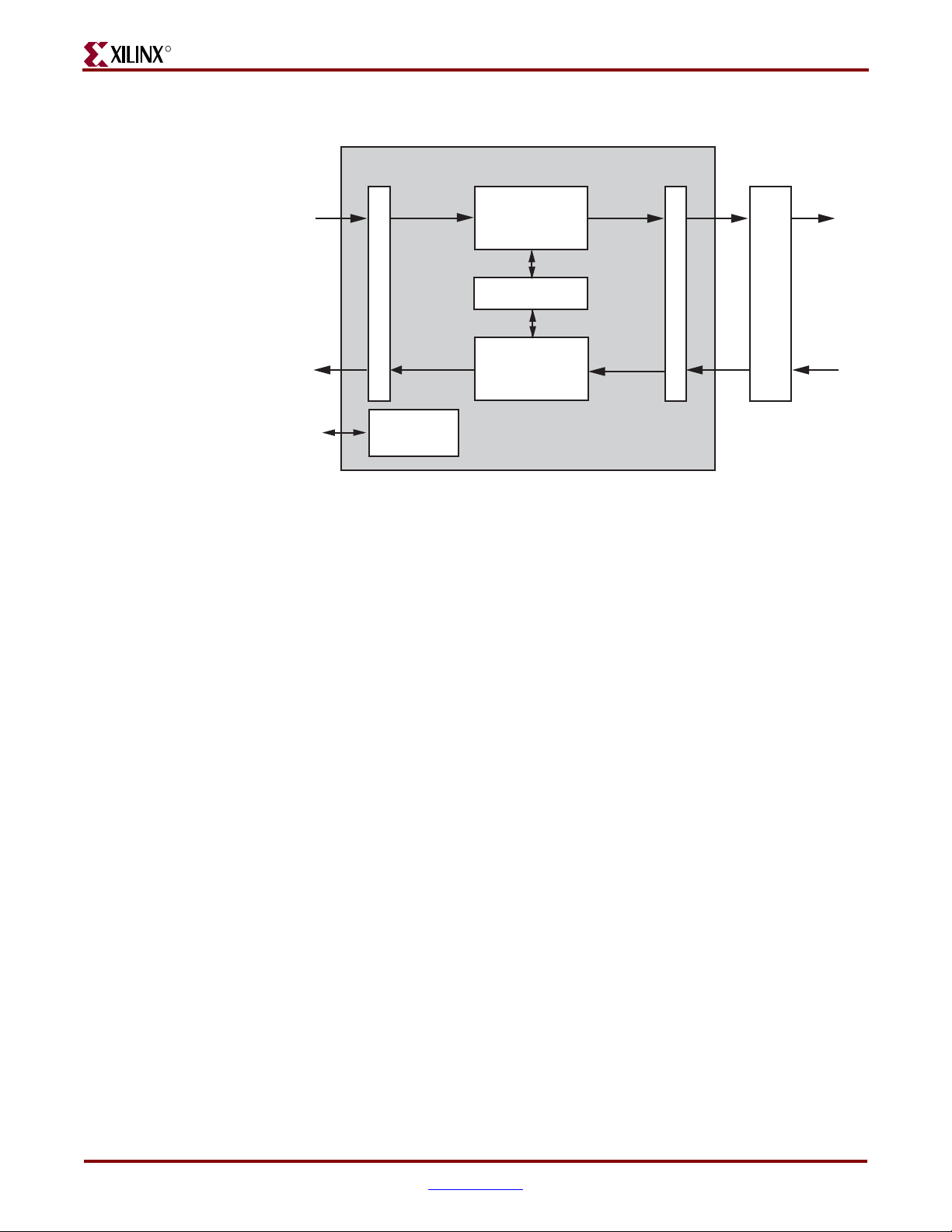
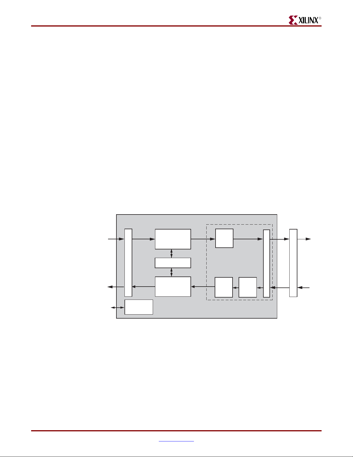
Figure 2-1 illustrates the remaining PCS sublayer functionality, and also shows the major
functional blocks of the core.
Ethernet 1000BASE-X PCS/PMA or SGMII v9.1 www.xilinx.com 23
UG155 March 24, 2008
R
r
LogiCORE Ethernet 1000BASE-X PCS/PMA or SGMII Core
PCS Transmit Engine
Chapter 2: Core Architecture
GMII
to MAC
MDIO
Interface
GMII Block
Optional PCS
Management
Optional
Auto-Negotiation
PCS Receive Engine
and Synchronization
RocketIO I/F Block
RocketIO Transeiver
Figure 2-1: Functional Block Diagram Using RocketIO Transceiver
GMII Block
A client-side GMII is provided with the core, which can be used as an internal interface for
connection to an embedded Media Access Controller (MAC) or other custom logic.
Alternatively, the GMII may be routed to device IOBs to provide an external (off chip)
GMII.
PCS Transmit Engine
The PCS transmit engine converts the GMII data octets into a sequence of ordered sets by
implementing the state diagrams of IEEE 802.3 (figures 36-5 and 36-6). See Appendix D,
“1000BASE-X State Machines.”
To PMD
Sublaye
PCS Receive Engine and Synchronization
The synchronization process implements the state diagram of IEEE 802.3 (figure 36-9). The
PCS receive engine converts the sequence of ordered sets to GMII data octets by
implementing the state diagrams of IEEE 802.3 (figures 36-7a and 36-7b). See Appendix D,
“1000BASE-X State Machines.”
Optional Auto-Negotiation Block
IEEE 802.3 clause 37 describes the 1000BASE-X Auto-Negotiation function that allows a
device to advertise the modes of operation that it supports to a device at the remote end of
a link segment (link partner), and to detect corresponding operational modes that the link
partner may be advertising.
Auto-Negotiation is controlled and monitored through the PCS Management Registers.
See Chapter 10, “Auto-Negotiation.”
24 www.xilinx.com Ethernet 1000BASE-X PCS/PMA or SGMII v9.1
UG155 March 24, 2008
System Overview
Ethernet 1000BASE-X PCS/PMA or SGMII with Ten-Bit-Interface
R
Optional PCS Management Registers
Configuration and status of the core, including access to and from the optional AutoNegotiation function, uses the 1000BASE-X PCS Management Registers defined in IEEE
802.3 clause 37. These registers are accessed through the serial Management Data
Input/Output Interface (MDIO), defined in IEEE 802.3 clause 22, as if it were an externally
connected PHY.
The PCS Management Registers may be omitted from the core when the core is performing
the 1000BASE-X standard. In this situation, configuration and status of the core is made
possible with the use of an alternative configuration vector and a status signal.
When the core is performing the SGMII standard, the PCS Management Registers become
mandatory and information in the registers takes on a different interpretation. For more
information, see “Management Registers” in Chapter 9.
RocketIO Interface Block
The RocketIO Interface Block enables the core to connect to a Virtex-II Pro, Virtex-4, or
Virtex-5 FPGA RocketIO transceiver.
The Ethernet 1000BASE-X PCS/PMA or SGMII core, when used with the Ten-Bit Interface
(TBI), allows you to implement only the 1000BASE-X PCS sublayer.
LogiCORE Ethernet 1000BASE-X PCS/PMA or SGMII Core
8B/10B
Encoder
8B/10B
Decoder
RX
Elastic
Buffer
TBI
IOBs
TBI Block
to PMA
Sublayer
GMII
to MAC
MDIO
Interface
GMII Block
Optional PCS
Management
PCS Transmit Engine
Optional
Atuo-negotiation
PCS Receive Engine
and Synchronization
Figure 2-2: Functional Block Diagram with a Ten-Bit Interface
The optional TBI can be used in place of the RocketIO transceiver to provide a parallel
interface for connection to an external PMA SERDES device. In this implementation,
additional logic blocks are required to replace some of the RocketIO transceiver
functionality. These are shown in the surrounded by the dotted line box in Figure 2-2 and
are described in the following sections. The other blocks are described previously in this
document.
Ethernet 1000BASE-X PCS/PMA or SGMII v9.1 www.xilinx.com 25
UG155 March 24, 2008

R
8B/10B Encoder
8B10B encoding, as defined in IEEE 802.3 (Tables 36-1a to 36-1e and Table 36-2), is
implemented in a block SelectRAM™, configured as ROM, and used as a large look-up
table.
8B/10B Decoder
8B10B decoding, as defined in IEEE 802.3 (Table 36-1a to 36-1e and Table 36-2), is
implemented in a block SelectRAM, configured as ROM, and used as a large look-up table.
Receiver Elastic Buffer
The Receiver Elastic Buffer enables the 10-bit parallel TBI data, received from the PMA
sublayer synchronously to the TBI receiver clocks, to be transferred onto the cores internal
125 MHz clock domain. It is an asynchronous FIFO implemented in internal RAM. The
Receiver Elastic Buffer attempts to maintain a constant occupancy by inserting or
removing Idle sequences as necessary. This causes no corruption to the frames of data.
TBI Block
The core provides a TBI interface that should be routed to device IOBs to provide an offchip TBI.
Chapter 2: Core Architecture
Core Interfaces
All ports of the core are internal connections in FPGA fabric. An HDL example design
(delivered with the core) connects the core, where appropriate, to a RocketIO transceiver,
and/or add IBUFs, OBUFs, and IOB flip-flops to the external signals of the GMII and TBI.
IOBs are added to the remaining unconnected ports to take the example design through
the Xilinx implementation software.
All clock management logic is placed in this example design, allowing you more flexibility
in implementation (such as designs using multiple cores). This example design is provided
in both VHDL and Verilog. For more information, see the Ethernet 1000BASE-X PCS/PMA
or SGMII Getting Started Guide.
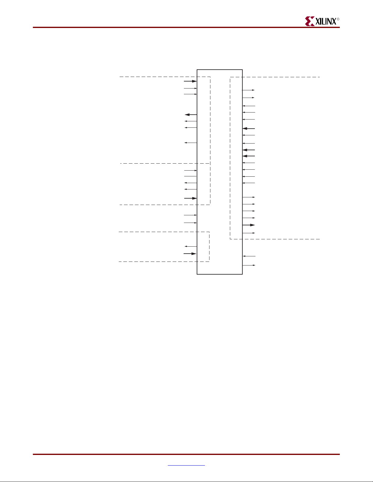
Figure 2-3 shows the pinout for the Ethernet 1000BASE-X PCS/PMA or SGMII core using
a RocketIO transceiver with the optional PCS Management Registers. The signals shown in
the Auto-Negotiation box included only when the core includes the Auto-Negotiation
26 www.xilinx.com Ethernet 1000BASE-X PCS/PMA or SGMII v9.1
UG155 March 24, 2008
Core Interfaces
R
functionality. For more information, see Chapter 3, “Generating and Customizing the
Core.”
GMII
MDIO
Auto_Negotiation
gmii_txd[7:0]
gmii_tx_en
gmii_tx_er
gmii_rxd[7:0]
gmii_rx_dv
gmii_rx_er
gmii_isolate
mdc
mdio_in
mdio_out
mdio_tri
phyad[4:0]
reset
gtx_clk
an_interrupt
link_timer_value[8:0]
RocketIO Interface
mgt_rx_reset
mgt_tx_reset
userclk
userclk2
dcm_locked
rxbufstatus[1:0]
rxchariscomma
rxcharisk
rxclkcorcnt[2:0]
rxdata[7:0]
rxdisperr
rxnotintable
rxrundisp
txbuferr
powerdown
txchardispmode
txchardispval
txcharisk
txdata
enablealign
signal_detect
status_vector[4:0]
Figure 2-3: Component Pinout Using RocketIO Transceiver
with PCS Management Registers
Ethernet 1000BASE-X PCS/PMA or SGMII v9.1 www.xilinx.com 27
UG155 March 24, 2008
R
Chapter 2: Core Architecture
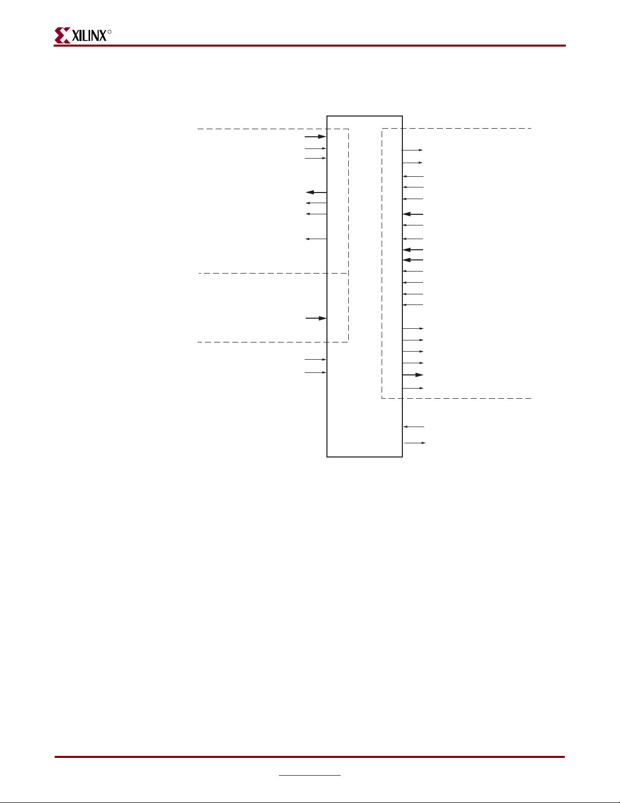
Figure 2-4 shows the pinout for the Ethernet 1000BASE-X PCS/PMA or SGMII core using
a RocketIO transceiver without the optional PCS Management Registers
GMII
MDIO Replacement
configuration_vector[3:0]
gmii_txd[7:0]
gmii_tx_en
gmii_tx_er
gmii_rxd[7:0]
gmii_rx_dv
gmii_rx_er
gmii_isolate
reset
gtx_clk
RocketIO Interface
mgt_rx_reset
mgt_tx_reset
userclk
userclk2
dcm_locked
rxbufstatus[1:0]
rxchariscomma
rxcharisk
rxclkcorcnt[2:0]
rxdata[7:0]
rxdisperr
rxnotintable
rxrundisp
txbuferr
powerdown
txchardispmode
txchardispval
txcharisk
txdata
enablealign
signal_detect
status_vector[4:0]
Figure 2-4: Component Pinout Using RocketIO Transceiver
without PCS Management Registers
28 www.xilinx.com Ethernet 1000BASE-X PCS/PMA or SGMII v9.1
UG155 March 24, 2008
Core Interfaces
R
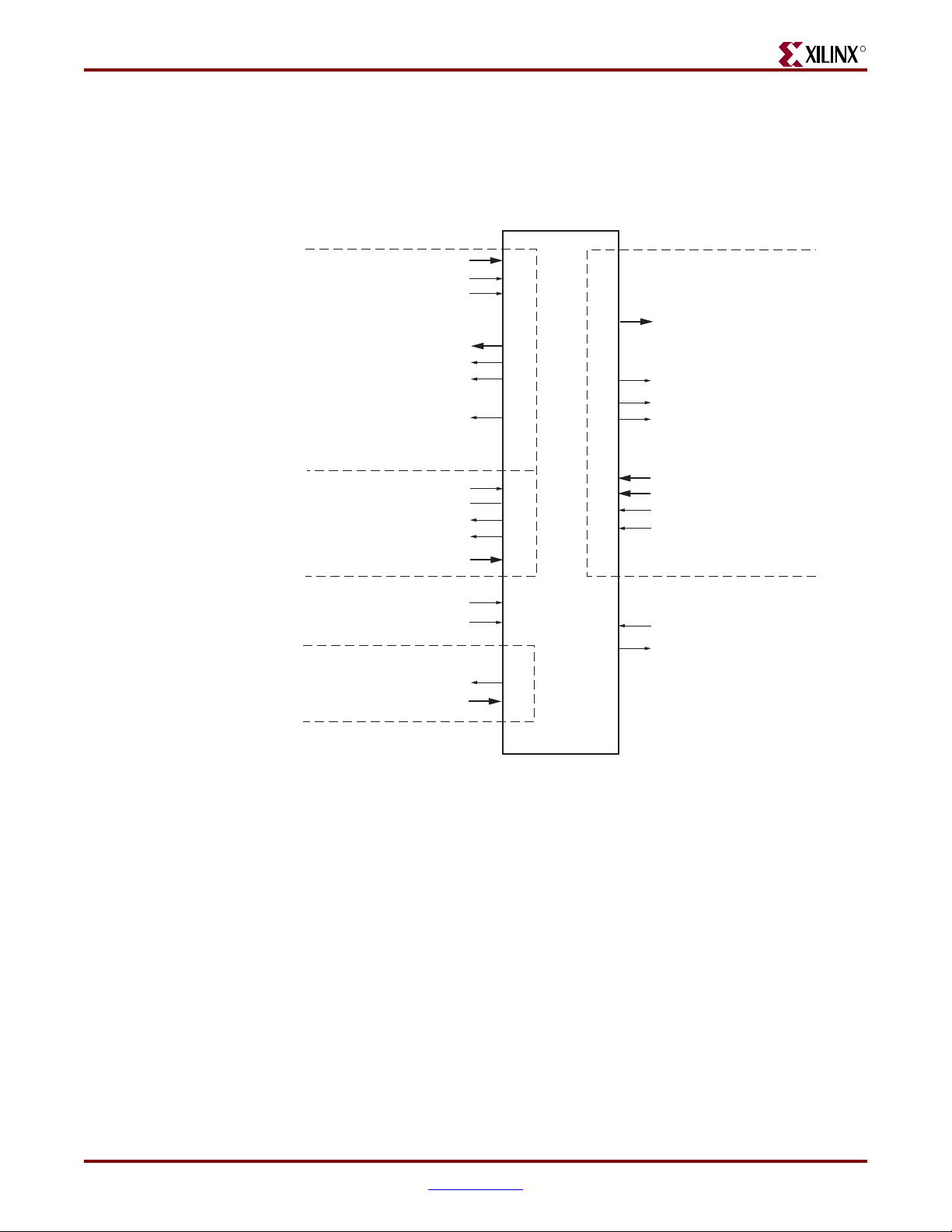
Figure 2-5 shows the pinout for the Ethernet 1000BASE-X PCS/PMA or SGMII core when
using the TBI with optional PCS Management Registers. The signals shown in the AutoNegotiation box are included only when the core includes the Auto-Negotiation
functionality (see Chapter 3, “Generating and Customizing the Core”).
).
GMII
MDIO
Auto_Negotiation
gmii_txd[7:0]
gmii_tx_en
gmii_tx_er
gmii_rxd[7:0]
gmii_rx_dv
gmii_rx_er
gmii_isolate
mdc
mdio_in
mdio_out
mdio_tri
phyad[4:0]
reset
gtx_clk
an_interrupt
link_timer_value[8:0]
Ten-Bit Interface (TBI)
tx_code_group[9:0]
loc_ref
ewrap
en_cdet
rx_code_group0[9:0]
rx_code_group1[9:0]
pma_rx_clk0
pma_rx_clk1
signal_detect
status_vector[4:0]
Figure 2-5: Component Pinout Using the Ten-Bit Interface
with PCS Management Registers
Ethernet 1000BASE-X PCS/PMA or SGMII v9.1 www.xilinx.com 29
UG155 March 24, 2008

R
Chapter 2: Core Architecture
Figure 2-6 shows the pinout for the Ethernet 1000BASE-X PCS/PMA or SGMII core when
using a TBI without the optional PCS Management Registers.
GMII
MDIO Replacement
configuration_vector[3:0]
gmii_txd[7:0]
gmii_tx_en
gmii_tx_er
gmii_rxd[7:0]
gmii_rx_dv
gmii_rx_er
gmii_isolate
reset
gtx_clk
Ten-Bit Interface (TBI)
tx_code_group[9:0]
loc_ref
ewrap
en_cdet
rx_code_group0[9:0]
rx_code_group1[9:0]
pma_rx_clk0
pma_rx_clk1
signal_detect
status_vector[4:0]
Figure 2-6: Component Pinout Using Ten-Bit Interface
without PCS Management Registers
30 www.xilinx.com Ethernet 1000BASE-X PCS/PMA or SGMII v9.1
UG155 March 24, 2008
Loading...