

Page 1

Version 4.8.1
MARCH 2021
Asset DB
Auditor
User Manual
Page 2

© 2021 Xerox Corporation. All rights reserved. Xerox® is a trademark of Xerox Corporation in the
United States and/or other countries. BRXXXXX
Other company trademarks are also acknowledged.
Document Version: 1.0 (April 2021).
Page 3

Auditor User Manual
- i - Asset DB v4.8.1
Table of Contents
1 GETTING STARTED ................................................................................................................. 1
1.1 Creating a New Project .............................................................................................. 1
1.2 Importing an Existing Project ..................................................................................... 1
1.3 Opening an Existing Project ...................................................................................... 2
2 WORKSPACE OVERVIEW ....................................................................................................... 3
3 FONT SCALING ........................................................................................................................ 3
4 LANGUAGE SETTINGS ........................................................................................................... 4
5 PROJECT STRUCTURE ........................................................................................................... 4
5.1 Creating a project structure ....................................................................................... 4
5.2 Searching within the project structure ....................................................................... 5
5.3 Marking project tree elements as complete or incomplete ........................................ 7
5.4 Assigning Sites, Buildings and Floors ....................................................................... 7
5.5 Project Contacts......................................................................................................... 8
5.6 Required Format for Floor Plans ............................................................................... 9
5.7 Making Changes to Floor Plans in Asset DB .......................................................... 10
6 SCALING FLOOR PLANS ...................................................................................................... 11
7 MEASUREMENT TOOL .......................................................................................................... 13
8 DEPARTMENT MAPPING ...................................................................................................... 13
8.1 Drawing Department Zones ..................................................................................... 14
9 ASSET TABLE VIEW .............................................................................................................. 16
9.1 Filtering Columns ..................................................................................................... 16
9.2 Table Tools .............................................................................................................. 17
10 PLOTTING ASSETS ............................................................................................................... 18
10.1 Positioning Icons from Icon Tab .............................................................................. 18
10.2 Unplotting Assets ..................................................................................................... 19
10.3 Plotting Icons from the Asset Table View ................................................................ 19
Page 4

Auditor User Manual
- ii - Asset DB v4.8.1
10.4 Adaptive Icons ......................................................................................................... 20
10.5 Types of Assets ....................................................................................................... 21
10.6 Make and Model Input ............................................................................................. 21
10.7 Meter Readings........................................................................................................ 23
10.8 Barcode Scanners ................................................................................................... 24
10.9 Digital Cameras ....................................................................................................... 24
10.10 Thumbnail Gallery .................................................................................................... 24
10.11 Copy and Paste ....................................................................................................... 25
10.12 General Navigation for Auditing ............................................................................... 26
11 VIEWING ASSET INFORMATION .......................................................................................... 26
11.1 Viewing the Web Page for a Device ........................................................................ 27
11.2 Search ...................................................................................................................... 27
11.3 Statistics ................................................................................................................... 28
11.4 Filter ......................................................................................................................... 28
12 FURTHER ASSET FUNCTIONS ............................................................................................. 29
12.1 Changing Device Type ............................................................................................ 29
12.2 Relocating Assets .................................................................................................... 29
12.3 Multiple Selection ..................................................................................................... 30
13 FLOOR NOTES ....................................................................................................................... 30
14 PREPARING PROJECT FOR EXPORT AND SHARING ...................................................... 31
14.1 Adjusting global settings in Asset DB ...................................................................... 31
15 ICON LABELS ......................................................................................................................... 32
15.1 Displaying labels ...................................................................................................... 32
15.2 Configuring labels .................................................................................................... 33
15.3 Customising Labels ................................................................................................. 34
15.4 Adding Borders to a Floor Plan ............................................................................... 36
15.5 Adjusting Floor plan Image Size .............................................................................. 36
15.6 Automated Label Placement ................................................................................... 37
16 FLOOR PLAN KEYS .............................................................................................................. 38
17 IMPORTING AND EXPORTING DATA .................................................................................. 39
17.1 Exporting Data ......................................................................................................... 39
Page 5

Auditor User Manual
- iii - Asset DB v4.8.1
17.2 Importing Data ......................................................................................................... 40
17.2.1 Import External Data ................................................................................................ 40
17.2.2 Using External Data before Mapping ...................................................................... 46
17.2.3 Date format when importing External Data ............................................................. 47
17.2.4 Import Asset DB Data .............................................................................................. 49
17.3 CSV Data Format .................................................................................................... 50
17.4 External Data Lookup .............................................................................................. 51
18 EXPORTING FLOOR PLANS ................................................................................................. 54
19 ICON CUSTOMISATION ......................................................................................................... 54
19.1 Icon Customisations ................................................................................................ 55
19.1.1 Icons ......................................................................................................................... 56
19.1.2 Icon Properties ......................................................................................................... 57
19.1.3 Colour Rules ............................................................................................................ 58
19.1.4 Fields ........................................................................................................................ 59
19.1.5 Validations ............................................................................................................... 61
19.1.6 Visibility .................................................................................................................... 62
19.2 Field Customisations ............................................................................................... 63
20 IMPORTING AND EXPORTING BACKUPS .......................................................................... 66
21 ORGANISING PROJECTS ..................................................................................................... 66
22 ASSET DB CLOUD ................................................................................................................. 68
22.1 How to connect to Asset DB Cloud ......................................................................... 68
22.2 Synchronising Projects ............................................................................................ 69
22.3 Project Notifications ................................................................................................. 72
23 DEACTIVATING YOUR ASSET DB LICENCE ...................................................................... 72
Page 6
Auditor User Manual
- 1 - Asset DB v4.8.1
1 Getting Started
There are three ways to begin using Asset DB when first opened.
1.1 Creating a New Project
To create a new project from scratch select File > New > Project1.
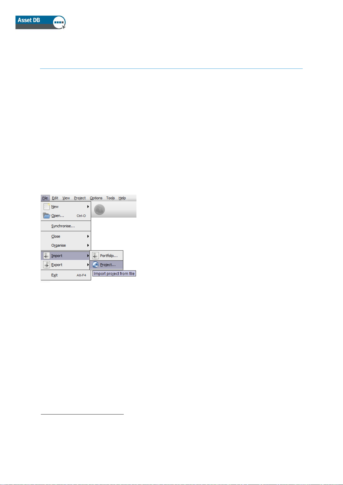
1.2 Importing an Existing Project
If an Asset DB project file or a project xml file has been supplied and is saved elsewhere on your
PC, go to File > Import > Project2 and navigate to the supplied file. Asset DB project files have
the extension ‘.atd’ and xml project files have the extension ‘.zip’.
Figure 1. Import > Project
Note: Import Project should only be used for loading new or backup project files rather than each
time the application is used. For day to day use of an existing project, use Open Project instead.
1
Create New project functionality is not available with all licence types
2
Import of .atd files is not available with all licence types
Page 7
Auditor User Manual
- 2 - Asset DB v4.8.1
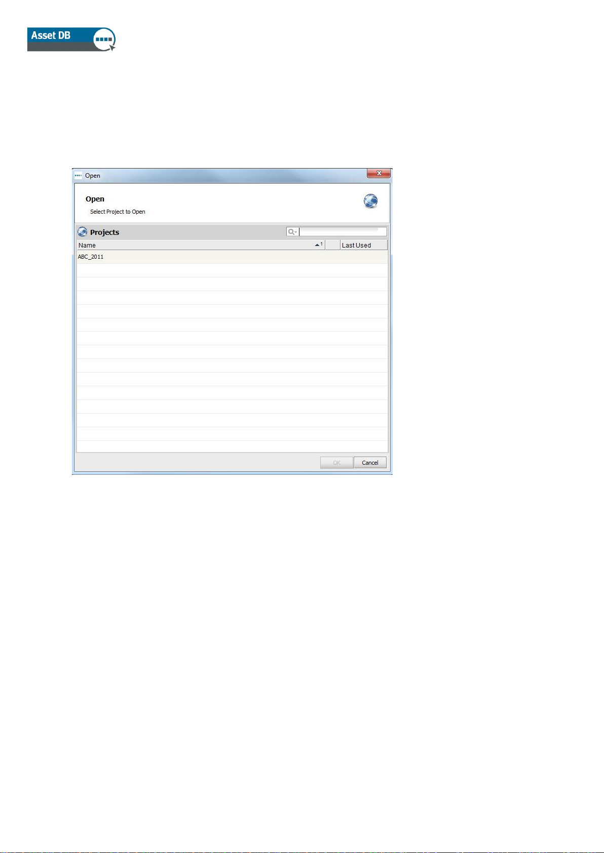
1.3 Opening an Existing Project
Go to File > Open or click the Open Project button at the top left to open a pop-up containing the
list of available projects. Select the desired project from the list and click “OK” to open.
Figure 2. Open Project
You can sort the “Name” and “Last Used” columns by clicking in the header. You can also search
for a project using the search bar in the top right.
If you have a TCO Analysis, Green Calculation, or Solution linked to a project, you can
simultaneously select it along with the project and open both together at the same time if your
licence level permits this. Please refer to the Analyst or Architect Manual for further assistance.
Page 8
Auditor User Manual
- 3 - Asset DB v4.8.1
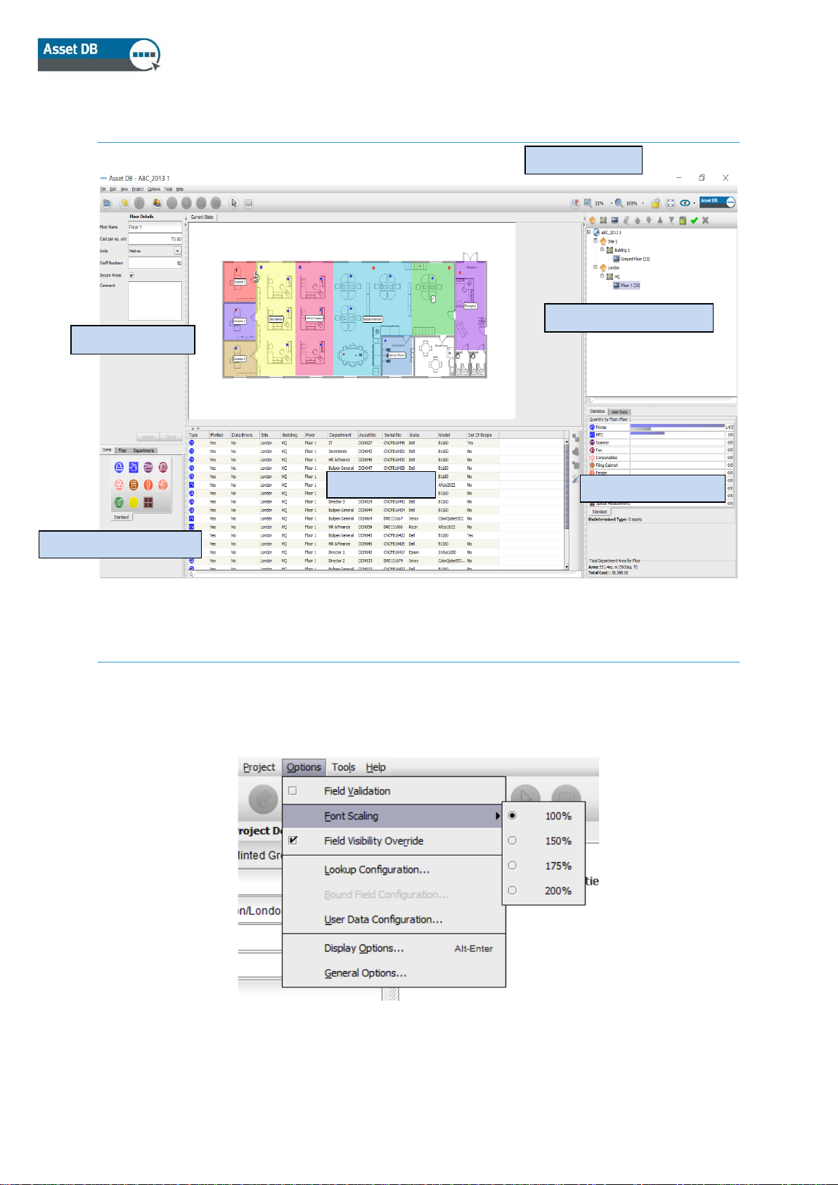
2 Workspace Overview
Figure 3. Workspace overview
3 Font Scaling
To optimise the Asset DB interface for different screen resolutions go to Options >Font Scaling
and select the amount you want your font to increase. Once selected, a pop-up window will
appear advising you that the changes will only take effect once Asset DB is restarted.
Figure 4. Font Scaling
Zoom Control
Statistics Console
Organisation Console
Asset Table
Details
Tabbed Tool Console
Page 9
Auditor User Manual
- 4 - Asset DB v4.8.1
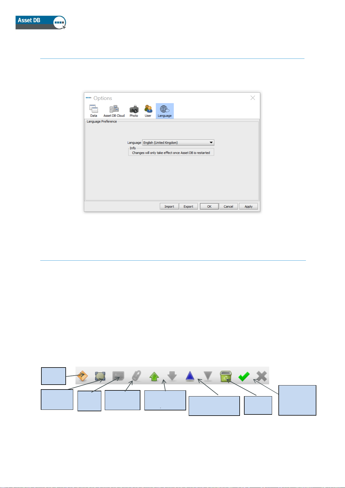
4 Language Settings
Go to Options >General Options and select the Language tab in the pop-up. You will then be able
change your Asset DB language here. Changes will only take effect once Asset DB is restarted.
Figure 5. Language Selection
5 Project Structure
5.1 Creating a project structure
The console to the top right of the floor workspace is used to build the logical structure of your
organisation as shown in Figure 3. An organisation is represented as a tree of objects comprised
in hierarchical order of project, site, building, and floor. To add a new object, simply select the
parent object in the tree then click the appropriate button found in the toolbar above the tree. For
example, to add a new building to a site, click the site to which you wish to add a building, then
click the Add Building button in the toolbar, see Figure 6.
The tool bar at the top of the Organisation Console has several functions. Other than adding
sites, buildings, floors you can also attach floor plans, move objects up and down, sort objects in
ascending or descending order and mark sites, buildings and floors as complete.
Figure 6. Project organisation tree actions
Delete
Object
New
Floor
New
Building
New
Attach
Sort
Ascending/
Move
object up/
Mark
Object as
Complete
Page 10
Auditor User Manual
- 5 - Asset DB v4.8.1
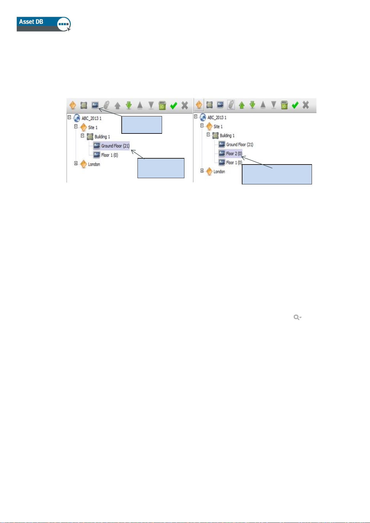
Within the Project Tree, you will see the hierarchical organisation of floors within a building,
buildings within a site and sites within a project. If you choose to insert a secondary object within
a parent object, this object will appear directly below the selected object and not directly at the
bottom of the list. This will be the case whether inserting a site, building or floor (see Figure 7).
Figure 7. Inserting secondary objects
To sort objects in the list, use the green arrows to move objects up or down. To sort within a
parent object you can use the blue triangle icons to sort child objects alphabetically, e.g. to sort
floors within buildings or buildings within sites, etc.
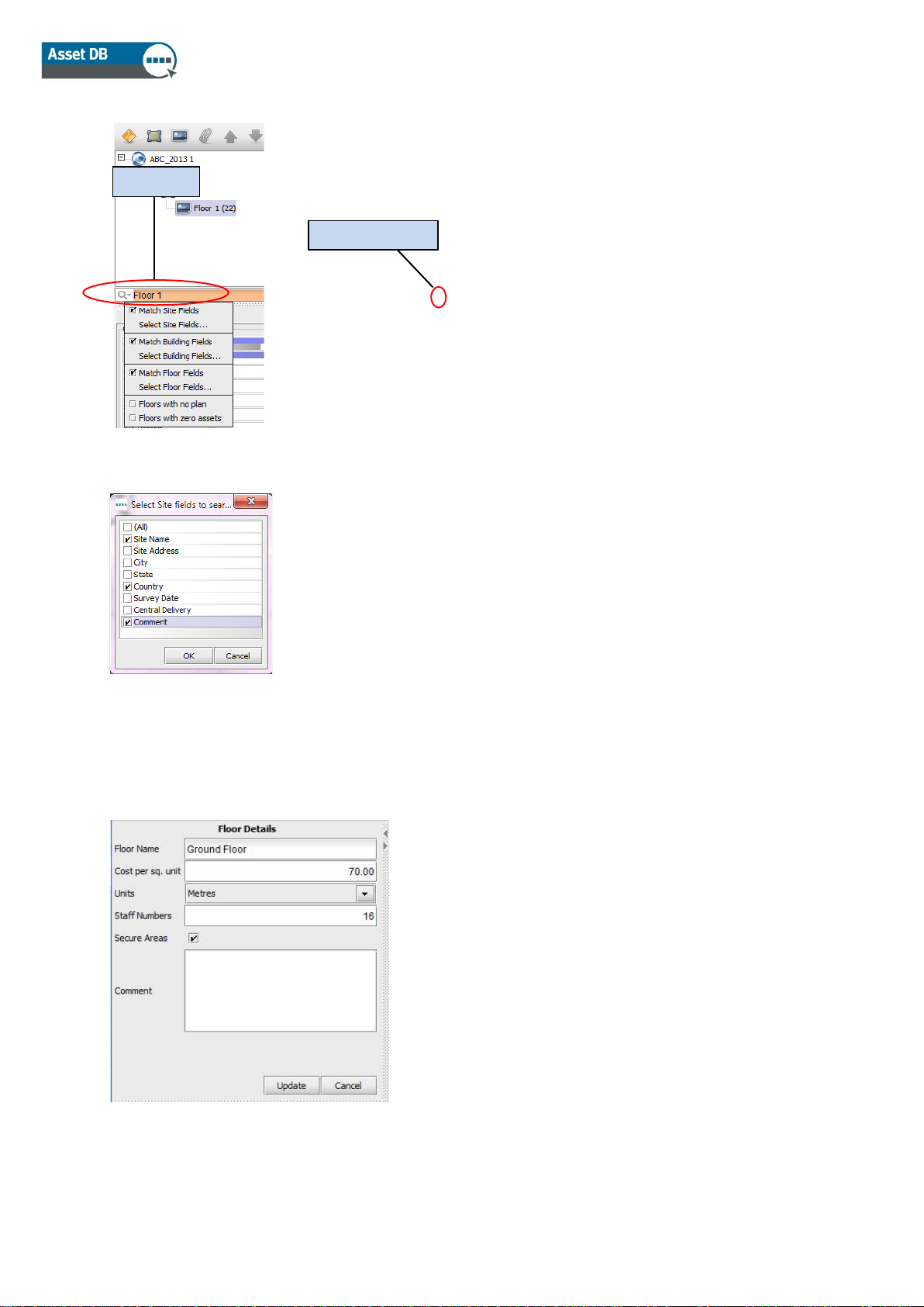
5.2 Searching within the project structure
Searching for objects within the Organisation Console is possible through the search bar located
at the bottom of the console (see Figure 8). By default, the search will run on the object name but
you can choose to include other data fields in the search by clicking the search button to the
left of the search field, selecting the level for which you would like to include more data fields and
then ticking the fields you would like to be included in the following pop-up (see Figure 9).
Note: the search acts as a filter and will hide objects from view. In order to show all sites,
buildings and floors again you must clear the search bar using the grey cross icon to the right of
the search field (see Figure 8).
Ground
Floor
Floor 2 appears
below selected floor
Add Floor
Page 11
Auditor User Manual
- 6 - Asset DB v4.8.1
Figure 8. Search
Figure 9. Select Site fields to include in search
Once a new object has been added to the tree, its details may be changed in the console at the
top left hand side of the screen.
Figure 10. Floor Details
Clear search
Search
Page 12
Auditor User Manual
- 7 - Asset DB v4.8.1
At floor level, digital images of floor plans may be attached by selecting the paperclip icon (see
Figure 6). Should the floor or other level be added in the wrong place in the organisational tree, it
may be repositioned up or down within that level using the arrow buttons or deleted entirely using
the Delete button (also in Figure 6).
5.3 Marking project tree elements as complete or incomplete
In the project tree, it is possible to select sites, buildings, and floors and then to mark them as
complete.
This might be a good idea when different parts of the project have been assigned to different
people (see section 22 for more details), in order to have an overview as to how much work has
been done so far.
To mark an element as complete, simply select it in the project tree and then click on the green
tick in the Project Tree console (see Figure 8). The element will then show a green tick next
to it. Once synchronised with the Asset DB Cloud (see section 22), these changes can then be
downloaded by other users. If an element has erroneously been marked as complete, the green
tick can be removed by selecting the element in the project tree and then clicking on the red cross
.
5.4 Assigning Sites, Buildings and Floors
Once you have connected to the Asset DB Cloud and synchronised your project (See section 21),
you have the possibility of assigning a name to each site, building, and floor. This facilitates
collaboration between several people on a same project by making it clear who should be
working on which element.
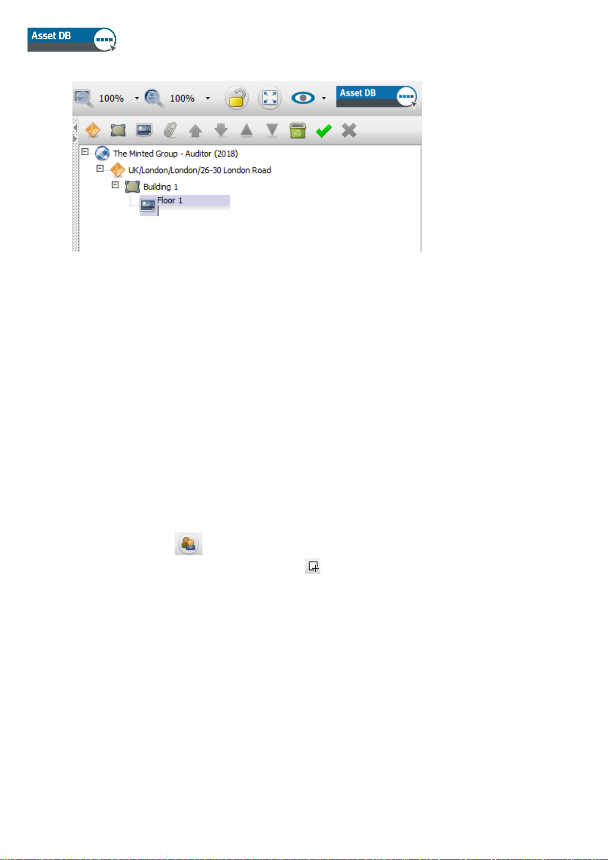
To do this you need to double click on a site, building or floor in the project tree and a second line
will become visible in which you can enter a person’s name. (See Figure 11)
Page 13
Auditor User Manual
- 8 - Asset DB v4.8.1
Figure 11. Assigning a Floor
Once a name is entered, hit ENTER and it is saved. If anyone else is working on the project
simultaneously and is also connected to the Asset DB Cloud, they will see these updates
instantly.
Please note that when you duplicate a project with assignments in the Project Tree, then these
assignments will be lost as they are stored on the server and not in the project itself.
5.5 Project Contacts
Contacts are project specific and are synchronised to the Asset DB Cloud when the project is.
Project contacts can be added in several ways:
The first is to use the button. This will open up a dialogue box in which a list of contacts
can be added. To create a new contact, click the button, fill in the required fields then click
Add. To edit a contact, select them in the list, make the necessary changes then click Update.
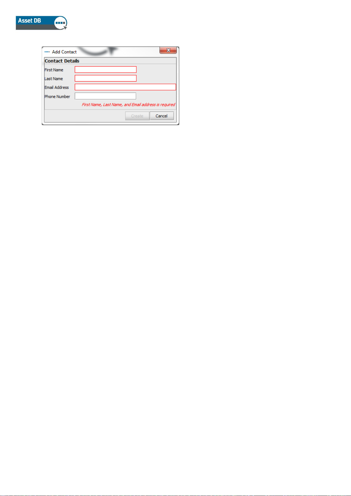
The second way of adding contacts is to do it directly from the “Contact” field. Clicking on the
magnifying glass will bring up the list of existing contacts with at the top of it, the option to add
new contacts. This will open the dialogue box shown in Figure 12.
Page 14
Auditor User Manual
- 9 - Asset DB v4.8.1
Figure 12. Add Contact
Fill in the contact details then click “Create”.
Once a list of contacts has been set up, they can be assigned to buildings or assets. The latter
requires the default icon customisations to be modified to include “Contact” fields (see section
18).
To assign an existing contact, start typing the contact name, email or phone number in the
Contact field and then pick from the drop-down list.
5.6 Required Format for Floor Plans
Asset DB requires that scanned floor plans are size A3 with a resolution of 300dpi and 8bit colour
depth or less. The floor plan must not be any larger than 2400 x 1700 pixels. These settings are
optimal for speed of navigation and essential to the successful addition of floor plans. Floor plan
images larger than the maximum size cannot be added.
Supported file formats are:
▪ PNG (preferred format for computer generated images)
▪ JPEG (preferred format for scanned images)
▪ TIFF
▪ GIF
The optimal format is a computer generated PNG of less than 2MB per floor. If your floor plan is
above the recommended size, Asset DB will automatically scale this image to the maximum
recommended size. It is essential that the floor plan match the sizing criteria laid out above for it
to be successfully added to your project.
Page 15
Auditor User Manual
- 10 - Asset DB v4.8.1
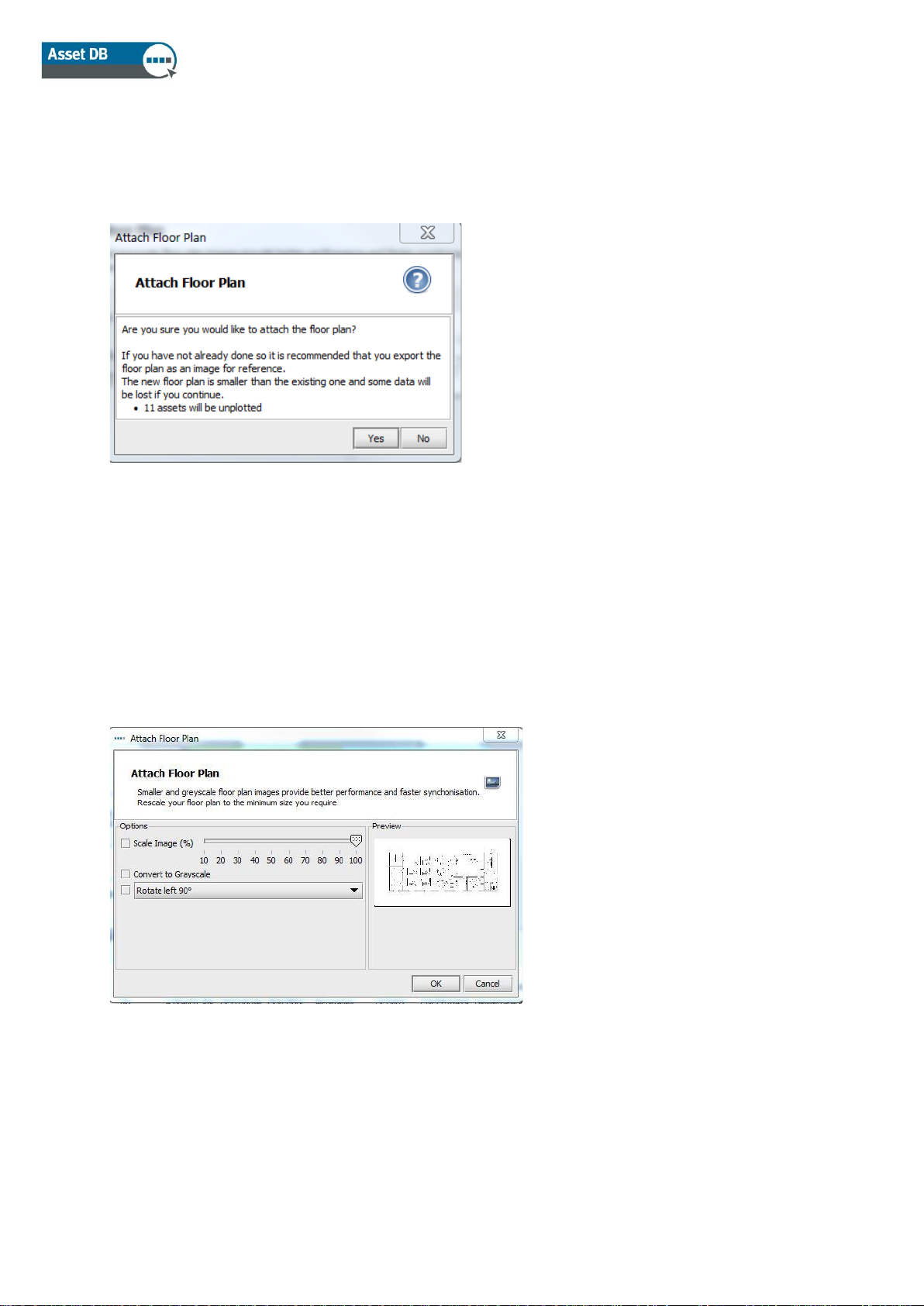
Adding a floor plan to a floor that already has assets plotted (see section 9) may cause assets to
be misaligned with the new floor plan or be un-plotted if they fall outside the boundaries of the
new floor plan. If this occurs, you will be warned via the pop-up in Figure 13.
Figure 13. Attach Floor Plan warning
5.7 Making Changes to Floor Plans in Asset DB
After selecting a floor plan to import, there will be a pop up with options for adjusting your floor
plan.
Figure 14. Attach Floor Plan dialogue
Here you have the option to decrease the image size, convert your floor plan to grayscale or
rotate it. These changes should be made before you plot any icons on the floor, as the icons will
not rotate or scale with the floor plan.
Page 16
Auditor User Manual
- 11 - Asset DB v4.8.1
6 Scaling Floor Plans
To be able to measure distances, the floor plan must be drawn to scale and you must set the
scale using the Scale Floor tool. To scale the floor plan you will need to know the length in feet or
metres of a particular section on the floor plan. Typically this would be the length of a wall or
partition or the width of a doorway.
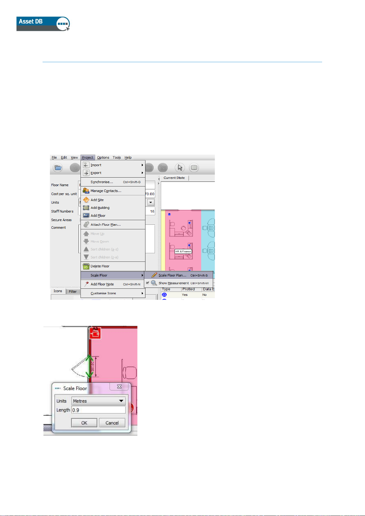
To set the scale of the floor plan use either Project > Scale Floor > Scale Floor Plan (Ctrl+Shift-S)
or use the “Scale Floor Plan” button at the bottom of the Statistics tab.
Figure 15. Select the Scale tool
Figure 16. Enter a scale for the line drawn
Top tip: Standard doorways are typically 0.9 metres or 3 feet in width.
Once selected, your cursor will appear as
crosshairs. Click to place the start point of the
object you are using to scale the floor. At this
point your cursor will create a double ended
arrow. Find your end point, and click again to
complete the arrow. Once your scale line is
drawn use the pop-up dialogue to define the
length of that line in feet or metres.
Page 17

Auditor User Manual
- 12 - Asset DB v4.8.1
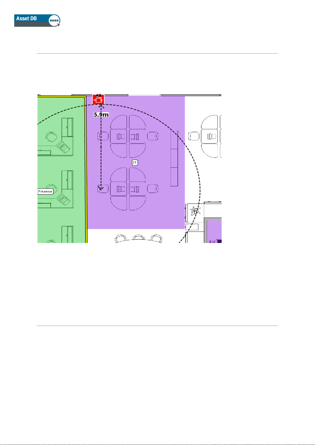
To verify that you have set your scale correctly, use the Measure Tool as described in section 7.
The measurement will remain on the floor. You can toggle the green measurement arrow on and
off by using Project > Scale Floor > Show Measurement (Ctrl+Shift-M). This will show or hide the
arrow and measurement that was entered as shown in Figure 17.
Figure 17. Show scaled floor measurement
Page 18
Auditor User Manual
- 13 - Asset DB v4.8.1
7 Measurement Tool
The measurement tool allows you to measure distances from one point to another point on a
scaled floor plan and also a circular radius around the measurement. This is dependent on setting
a scale for the floor (described in section 6).
Figure 18. Measurement tool
Select Measure from the Tools menu and simply click and drag away from a point on the floor
plan to display the distance measurement. A click of the mouse or a tap on the tablet pen will
make it disappear. To deselect the measurement tool, click on the Cursor icon.
8 Department Mapping
The first step you should perform before placing any of your assets onto the floor plan is to define
your department names and draw your departments on the plan. By defining your departments
first, the department drop down in the asset detail window (explained in section 7.1) will populate
automatically, speeding up the input process.
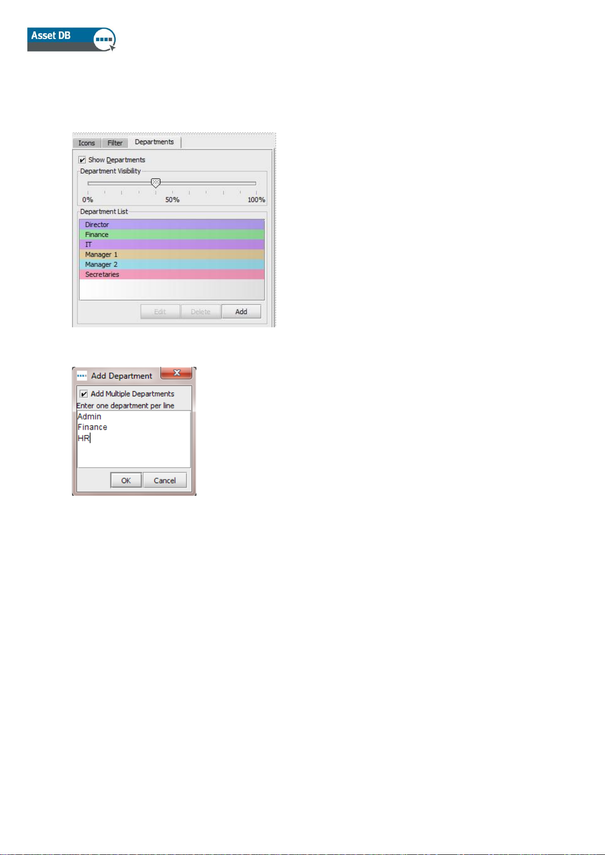
The Departments tab (see Figure 19) enables you to define your departments. Click the “Add”
button, name your department and choose a colour for that department. If you decide to change a
colour for the department click the “Edit” button to amend. Repeat this process until you have
defined all departments. You can add more departments later on in the process as needed.
Page 19
Auditor User Manual
- 14 - Asset DB v4.8.1
Top Tip: Choose bold colours for each department to give you more control over how brightly
they appear on your floor plan.
Figure 19. Departments Tab
Figure 20. Adding Multiple Departments
8.1 Drawing Department Zones
On the Department tab, select a department from the list you created earlier and click the “Draw”
button. Your cursor will appear as crosshairs. You can now draw a rectangular department on the
floor by clicking in one corner and dragging away to the opposite corner of the department.
The four corners will show as black nodes, each of which can be moved to suit the shape of the
department you are mapping.
New nodes can also be added as required by clicking on one of the edges of the department and
dragging away as shown in Figure 21.
Multiple departments can be added at the same time if
required by clicking the “Add Multiple Departments”
tick box in the Add Department pop-up. This allows
you to add a list of departments with each one inserted
on a new line (see Figure 20). Asset DB will then
assign a random colour to each entry. If the colour is
not suitable then it can be edited afterwards by
selecting the department from the list and clicking
“Edit”.
Page 20
Auditor User Manual
- 15 - Asset DB v4.8.1
Figure 21. Drawing departments
Alternatively, a department can be drawn by clicking on the floor plan to place points marking the
corners of the department zone. To complete, hover over the first point until you see a yellow
border around it and then click on the first point again. Once your department zone is drawn you
can select it by clicking anywhere within it. Just like a rectangular department, this type of
department map can also be amended by moving existing nodes or creating new ones.
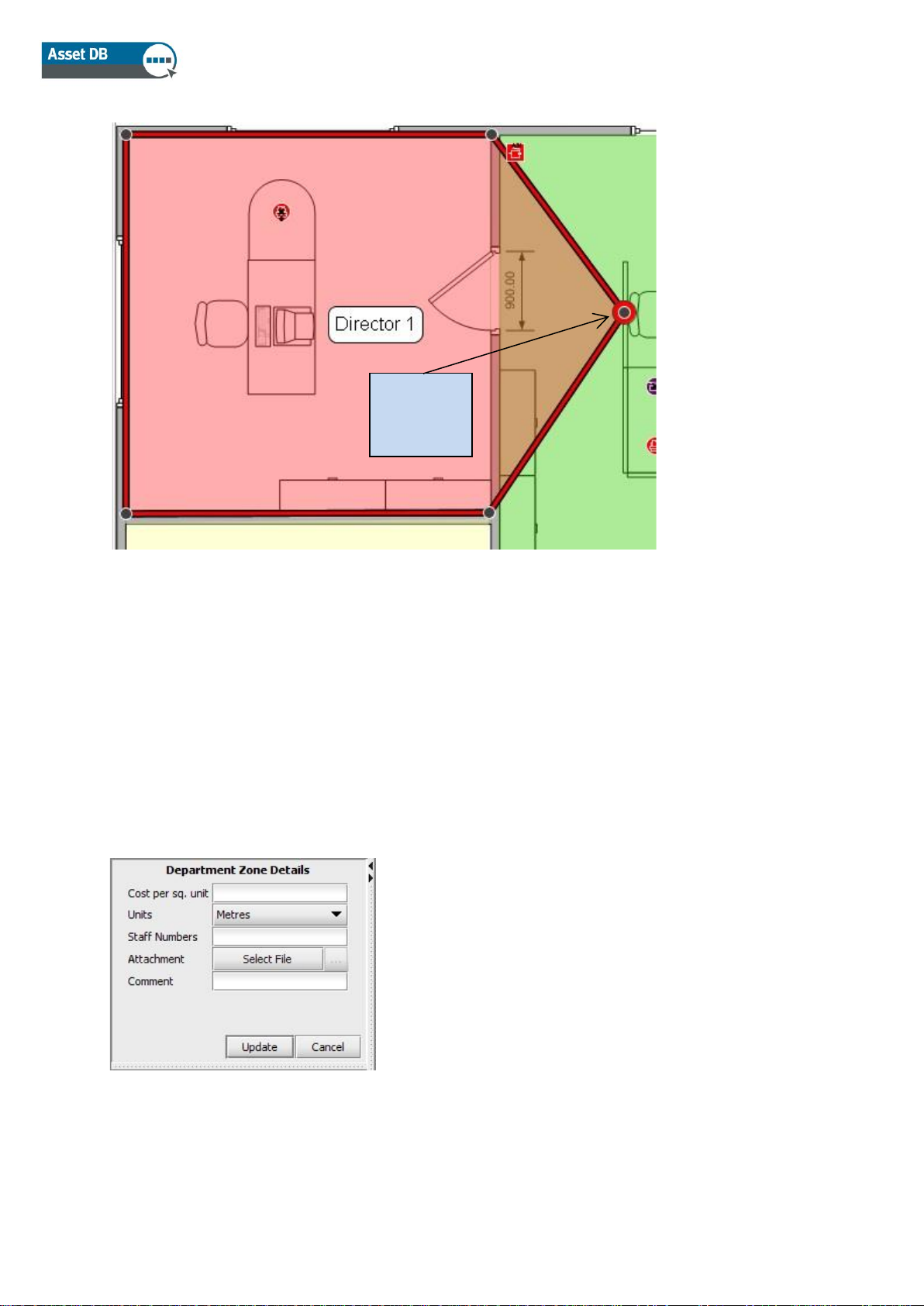
The cost per square foot/metre for a department zone can be entered in the details console to the
left of the workspace. Please note that a cost may be entered at any level in the organisation tree
but costs defined lower in the tree will override costs defined at higher levels.
Figure 22. Enter cost details for the department zone
Once a department is drawn, the name of that department will appear in a box within the
department zone. You can drag this box around the department zone to find a suitable place for
Newly
created
node
Page 21
Auditor User Manual
- 16 - Asset DB v4.8.1
it, but it will not move outside the area you have drawn. You can change the colour and size of
this label by going to Options > Display Options (Alt-Enter) and choosing the Departments tab.
A department zone can be deleted by selecting the zone on the floor plan and using the Delete
icon in the tool bar or pressing the Delete key. Deleting a department zone from the floor plan will
not delete any assets within the zone. If you decide to place a new department over the assets,
those assets will be automatically assigned to the newly created department zone.
9 Asset Table View
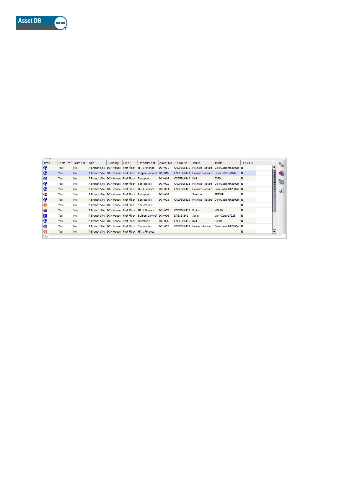
Figure 23. Table View
The table view allows you to view and filter your assets based on a variety of criteria. You can
expand or collapse the table by dragging the top bar up or down.
To change the visible columns, right click in any column header bar and choose from the options
on the menu. When you click “More” a list of available columns to add to the table will display,
allowing you to decide which columns you are viewing.
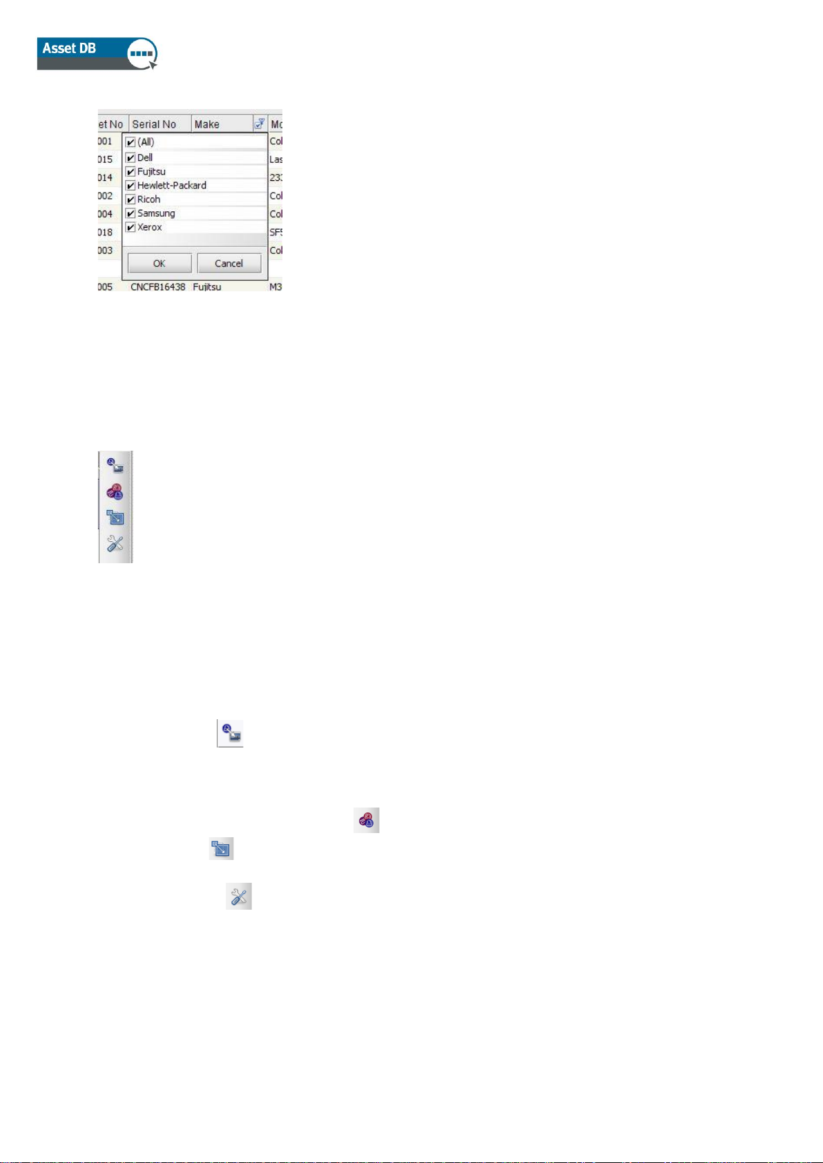
9.1 Filtering Columns
Columns in the table can be filtered by clicking on the right side of the column header as shown in
Figure 24. To show only one make of devices, you remove the tick marks from the others. To
take off the filter, click “All” or right click on the heading bar and select Clear All Filters.
Page 22
Auditor User Manual
- 17 - Asset DB v4.8.1
Figure 24. Filter View
9.2 Table Tools
Figure 25. Table Tools
On the right side of the table, there are 4 buttons for you to use in conjunction with the table. They
perform the following functions.
• Plot Asset - Described in section 10.3, this button allows you to plot an asset on your
table that is not yet positioned on a floor plan
• Change the Asset Type- Asset DB will assign a type of device to a model when it is
imported into the table (Section 17.2.2). To change it, or to set it in the first place if a
device is not recognised, select and choose the correct icon.
• Relocate - Allows you to relocate a device to a new floor. More information on
relocation can be found in section 12.2.
• Tool Button - Allows you to change settings on the table. The option to show assets
without a floor is found here.
Page 23
Auditor User Manual
- 18 - Asset DB v4.8.1
10 Plotting Assets
10.1 Positioning Icons from Icon Tab
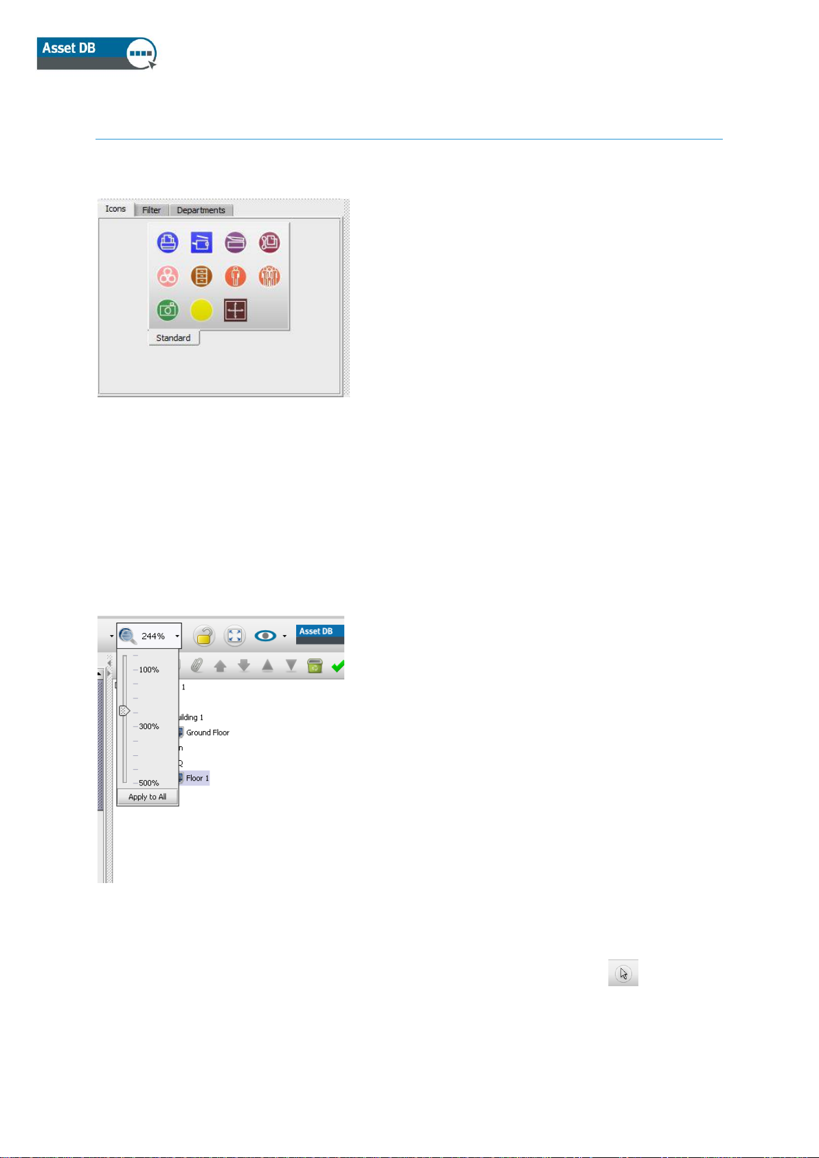
Figure 26. Icon Tab
The Icons tab to the bottom left of the workspace can be used to select assets to be placed onto
the floor plan. To see what each icon represents, hover over it to display a description. After
clicking on the appropriate icon, it will “stick” to the cursor until placed on the floor plan by clicking
again in the desired location.
The icons can be resized using the slider shown in Figure 27.
Figure 27. Icon Size Slider
You can add more icons to your toolset if necessary. Instructions on how to add icons is found in
section 19. If an icon is selected unintentionally, you can click the Cursor button at the top of
the screen to cancel selection.
Page 24
Auditor User Manual
- 19 - Asset DB v4.8.1
Once an asset has been placed on the floor plan, details may be entered in the Asset Details
console to the top left of the workspace. When data entry is complete, click the Update button to
save the details.
If you are unhappy with the location of an asset, it can be moved by dragging it with the pen or
left mouse button.
Note: All actions such as placing and moving assets on the floor plan are instantly saved. The
application may be terminated at any time and no data will be lost.
10.2 Unplotting Assets
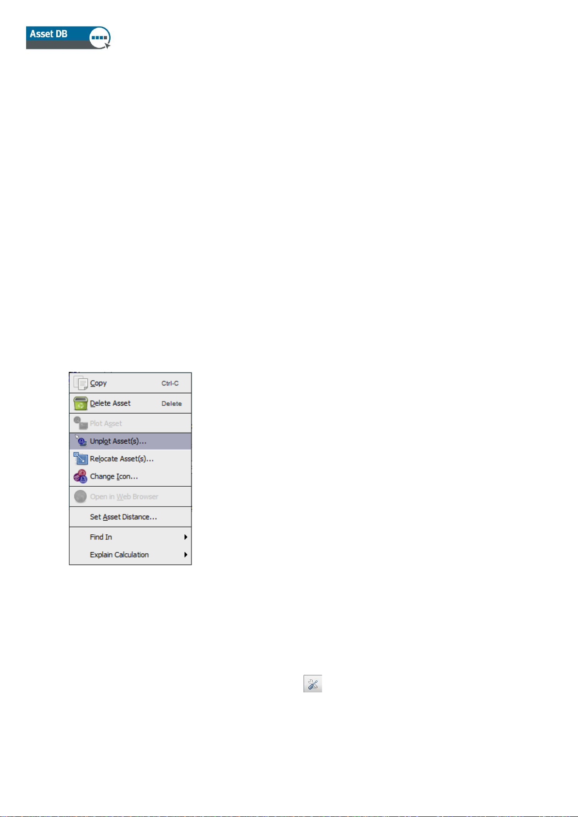
Once plotted on a floor plan; an asset can be removed by right clicking and selecting Unplot
Asset See Figure 28. The asset will be removed from the floor plan but will not be unassigned
from the floor. The asset will remain in the Asset Table below the Floor Plan window but removed
the icon will be removed from floor plan.
Figure 28. Unplotting an asset
10.3 Plotting Icons from the Asset Table View
After importing external data (Section 17.2.1) you may have some devices that are not plotted. To
see all devices that have not been plotted, first click and make sure the box is ticked in front
of Include assets without a floor. Then, click on the right hand side of the Plotted column header,
tick the box in front of False and untick True to show only unplotted assets. If False is not an
option, all of your devices have been plotted.
Page 25

Auditor User Manual
- 20 - Asset DB v4.8.1
Once you have a list of devices that have not been plotted, you can plot these devices. Click on
the device from the list and choose the Plot Asset button either from the right hand side of
the table, or by right-clicking on the device in the table and selecting it from the menu. This will
attach the icon to your cursor. Click on the floor to place the icon. You can also click on a device
from the list, and drag it onto the floor plan. Use the Search function described in Section 11.2 to
find the device you want to plot.
If the device does not yet have a type, you will be prompted to choose the correct icon as shown
in Figure 29.
Figure 29. Icon Selection
Once your device is on the floor plan, the Plotted column will change from No to Yes and the Site,
Building, and Floor columns will be populated.
If the Not Found field was ticked for an unplotted device, it will automatically become unticked
once the device is plotted.
10.4 Adaptive Icons
Some of the icons within Asset DB are adaptive, meaning they change dynamically to provide a
visual display of certain defined attributes. This powerful feature allows you to look at a floor plan
and determine at a glance which devices have nominated attributes, for example Colour Capable,
Inkjet, A3, Networked etc. Figure 30 shows how the icon formats change for these nominated
attributes.
Page 26

Auditor User Manual
- 21 - Asset DB v4.8.1
Figure 30. Printer indicators
Please note that the colours listed overleaf may not match what you see if you have customised
your icons to change colours based on different criteria. See section 19.1.3 for more information.
10.5 Types of Assets
There are two types of assets: Data Only assets such as electronic equipment; and Data with
Thumbnail Image assets such as storage units. All assets have an ID, which is used by Asset DB
to uniquely identify an asset and locate it on a floor plan. An asset’s ID is unique.
10.6 Make and Model Input
Electronic items have drop-down menus for speedy and error free input of make and model
information (see Figure 31). These makes and models are drawn from an extensive database
unique to Asset DB. The first nine makes that appear in this drop down menu will be the most
popular models. Data entered in other ways may not be found in the TCO database.
You can also begin to type the name of a make or model into the field, and options will appear
below the field for you to choose from. Type in the most unique part of the model name (e.g. the
model number without name or abbreviations) to get the best results.
Page 27

Auditor User Manual
- 22 - Asset DB v4.8.1
Figure 31. Make and model input
Note: The icon customisation feature (described in section 19.2) lets you mark any given data
field as mandatory. These fields appear with a red outline as shown in Figure 31. After entering
data for a device, a pop-up window will warn you if you have forgotten to enter mandatory data
(see Figure 32). This is only a warning and will not force you to go back and update.
Figure 32. Validation warning
Mandatory field notification can be switched off within Asset DB; this is especially useful if you are
working on a project after the audit such as for solution design purposes. To toggle this feature on
and off go to Options > Field Validation.
You may also set your own validation messages through icon customisations. This is explained in
section 19.1.5.
Page 28

Auditor User Manual
- 23 - Asset DB v4.8.1
Depending on which options you have selected for a device, further options may become visible.
For example, if you tick the Large Paper Capable box to indicate that the device in question is
able to print on large paper, you will be presented with an option to indicate if this function is in
use or not for the device in question.
10.7 Meter Readings
The capture of device meter readings is an important part of the audit process. Asset DB
facilitates this by allowing the capture of rolling meter readings.
Figure 33. Meter readings
Meter reading fields will be visible based on information entered on other tabs. For example,
Figure 33 shows meter readings for a colour multifunction device that is large paper capable and
scan enabled. If the scan enabled tick box was not marked on the capabilities screen, the Scan
meter reading field would not be visible. A mono A4 printer would only show you the Standard
Mono and Life Total fields.
In the specification tab, you can specify how many colour meter levels the device is capable of
tracking. For mono devices, this will usually be 0. For standard colour devices, this will usually be
1. For devices capable of capturing three colour levels, you can select 3 and capture the readings
for the three colour levels.
Note: If you have a Life Count meter reading field as part of your icon customisations, this entry
will not take part in the printer statistics calculation under the statistics tab or statistics export.
Only readings split by mono or colour will be calculated.
Meter reading data can also be populated from an external source. Please see section 17.2.1 for
more information.
Click to change or
delete
Add New
Date
Column
Page 29

Auditor User Manual
- 24 - Asset DB v4.8.1
10.8 Barcode Scanners
Barcode scanners may be used in the same way as keyboard input or handwriting recognition.
Place the cursor in the appropriate field then scan with the barcode scanner to populate it. By
programming the barcode scanner to emulate the <Tab> key after scanning, the cursor will
automatically move to the next field. Thus, if there are several pieces of bar-coded information to
be entered, the barcodes may simply be scanned one after the other without interruption.
10.9 Digital Cameras
Figure 34. A digital image associated with an asset
10.10 Thumbnail Gallery
Each item in the thumbnail gallery has its own set of fields.
It is important that these fields are completed correctly so that accurate statistical analysis can
take place automatically.
Once an asset type has been added to the gallery, the same asset type can be easily selected
from the gallery with its details already completed rather than input each time. A selected
thumbnail is highlighted in red (see Figure 35).
The ‘%’ symbol and ‘cm’ should not be added to the numerical data entered.
Assets with thumbnail pictures may require a digital
picture to be taken of the asset type. The camera
software should be launched for the addition of a new
thumbnail into the thumbnail gallery. The thumbnail
gallery is accessed using the button below the
thumbnail. Once an image is uploaded from the camera
it will appear in the thumbnail gallery.
Page 30

Auditor User Manual
- 25 - Asset DB v4.8.1
Important Note for Storage Assets: When entering the number of drawers for storage items
disregard vertical separators. This is important for statistical calculations. Number of drawers (or
shelves) should be horizontal drawers capable of holding an A4 file. The number of drawers is
then multiplied by the greater of length and depth of the unit and then by the percentage
utilisation to calculate linear metres of storage.
Figure 35. Thumbnail gallery
10.11 Copy and Paste
When adding a number of assets of the same type there are three ways to use the copy and
paste tool to save you having to repeatedly re-enter the same information:
• After inputting the first duplicated asset, press the Copy button. Clicking the Paste button
will then cause a duplicate icon to “stick” to the cursor and allow positioning on the floor
plan as normal.
• Alternatively you can right click on the device and select Copy from the drop down, then
right click again and select Paste.
• The third way is to select the asset, then use the Ctrl-C copy function and the Ctrl-V paste
function to stick the asset to your cursor ready to be positioned in the desired location.
Figure 36. Copy & paste asset
Page 31

Auditor User Manual
- 26 - Asset DB v4.8.1
10.12 General Navigation for Auditing
The floor plan for a floor may be viewed by clicking its icon in the organisation tree. The plan can
be moved by clicking on a free portion of the floor plan and dragging to the required position. The
floor plan may also be manipulated through a combination of using the zoom bar at the top of the
workspace, the reset zoom button and the scrollbars to the edge of the floor plan window.
When the correct floor has been selected, the available space for viewing the floor plan may be
increased by pressing the Expand button. This is a toggle button which will hide each of the side
panels in turn and then return you to the standard layout.
Figure 37. Expand/lock floor plan
All zoom and scroll settings are remembered from floor to floor within your Asset DB session.
11 Viewing Asset Information
To display or edit an asset’s data in the Asset Details console, select the asset by pressing with
the pen or left clicking with the mouse.
Top Tip: When reviewing assets, it is useful to lock the floor plan to prevent the accidental
movement of assets. This can be done by pressing the padlock toggle button at the top right of
the screen (see Figure 37.)
Page 32

Auditor User Manual
- 27 - Asset DB v4.8.1
11.1 Viewing the Web Page for a Device
Figure 38. View device web page
11.2 Search
The search bar is at the bottom of the window (see Figure 39). The search text can be entered
either via a keyboard/handwriting pad or via a barcode scanner. You can search for an asset
using several different criteria. To define the fields you are searching for, click the arrow next to
the magnifying glass and choose Select Fields to Search. This will allow you to choose any
one or multiple data fields to search. As you type in your search criteria, the list of assets will be
narrowed down in the table above. The search will be based on the level you have selected in the
project hierarchy. For example, if you are at the project level, the whole project will be searched
for that asset.
Figure 39. Search bar
To clear your search and return to a full list of assets, click on the cross to the right of the
search bar.
Search Bar
Most network enabled devices run an embedded web server. If
the IP address of the device has been populated, right-click on
the device on the floor plan and choose Open in Web Browser
to view the device’s web pages (see Figure 38).
Note: for this feature you must have an active network
connection to the network that the printer is on.
Page 33

Auditor User Manual
- 28 - Asset DB v4.8.1
11.3 Statistics
Summary information on the assets on a floor and department zone cost information can be
displayed using the statistics tab at the bottom right of the workspace. Statistics are displayed
based on the level of the project you currently have highlighted- project, building, floor or
department.
Figure 40. Asset statistics
11.4 Filter
Figure 41. Filter tab
In Scope
Out of
The filter tab may be used to hide and display
elements on the floor plan:
▪ Department zones may be turned on and off.
▪ All instances of a particular device type may be
displayed or hidden on the floor plan.
▪ If variable icons are being used, the variable
device colours and print indicators that appear
on the device icon can be turn off.
Note: These filters remain in effect when exporting
floor plans to PDF (see Section 18).
Page 34

Auditor User Manual
- 29 - Asset DB v4.8.1
12 Further Asset Functions
12.1 Changing Device Type
In some instances you may need to change the device type of an icon on the floor plan. For
example, you may have placed a printer on the floor and entered all the appropriate data then
realised it should be an MFP. To change the device type either highlight the device and use the
Edit > Change Icon menu or right click on the device in question, choose Change Icon and then
select the desired icon from the resulting pop-up. In most instances the data will be mapped to its
corresponding field (e.g. data in the Model field will remain in the Model field). In cases where the
corresponding field does not exist in the new device type, the data from the non-existent field will
be placed in the comment field.
12.2 Relocating Assets
From time to time assets will require relocation across floors. The relocation function is found
either by right clicking the asset or using the Relocate icon in the toolbar. A dialogue will appear
allowing you to select the destination floor. You will be redirected to the new floor. The asset will
not appear on your floor plan, but it will appear in your table for you to plot in the correct location.
It is also possible to relocate an asset to the project level, the result of which is that it will be
unplotted and no longer associated with a floor. This is done in the same way as relocating to a
different floor, only the project level must be selected instead (see Figure 42).
Figure 42. Relocate Assets
You can also relocate an asset directly from the table, by choosing the Relocate button on the
right hand side of the table or in the top toolbar (see Figure 43).
Figure 43. Relocate button
Page 35

Auditor User Manual
- 30 - Asset DB v4.8.1
12.3 Multiple Selection
You can select multiple icons at once in two ways. The first method is to hold down the control
key on the keyboard and click one device at a time. You can either select them from the map or
from the table. The selected items will all have a square behind them signifying that they are
selected.
The second method uses the Multiple Select icon located on the main toolbar. Simply click and
drag to form a drawn area on the map, and all the devices inside the drawn area will be selected.
Once selected, devices can be moved as a group, deleted or relocated to another floor.
Figure 44. Multiple select
13 Floor Notes
Floor notes can be added to the floor plan to share notes and ideas with other auditors or with the
solution architects. These are much like sticky notes as shown in Figure 45.
Figure 45. Floor Note
You can also pin the note to devices or areas of the floor by clicking on the pin in the top right
corner and dragging to the area you would like to pin the note to.
The look of the floor note can be changed by going to Options > Display Options (Alt+Enter) and
choosing the Floor Notes tab.
Page 36

Auditor User Manual
- 31 - Asset DB v4.8.1
14 Preparing Project for Export and Sharing
14.1 Adjusting global settings in Asset DB
More general settings for Asset DB can be managed through Options > General Options. This
pop-up has four overall settings that can determine:
- Data import and export settings
- Asset DB Cloud settings
- Photo import settings
- User name settings
See Figure 46 below.
Figure 46. Asset DB global settings menu
Within the User tab, there is a setting to “Prompt for a name at start-up”. This will mean that every
time Asset DB is opened, the user will have to enter a name before they can proceed. This will
then populate any data exported from the project with the name of the user who entered the data.
Page 37

Auditor User Manual
- 32 - Asset DB v4.8.1
15 Icon Labels
15.1 Displaying labels
Asset DB can show a label for each icon on a floor plan via the View > Icon Labels menu item.
Ticking the box will turn on the icon labels.
Figure 47. Displaying icon labels
Note: The same result can be obtained by going to Options>Display Options and ticking the
“Icon Label” box.
Page 38

Auditor User Manual
- 33 - Asset DB v4.8.1
15.2 Configuring labels
Asset DB gives you the option to create different configurations to modify labels, floor borders
and highlight colours depending on your needs or preferences, by going to Options>Display
Options. Once you have made the selection the Project Options window will be displayed (see
Figure 48)
Figure 48. Project Options
To create a new configuration simply select the “New” button and edit the name on the
“Configuration Name” field.
In addition to creating new configurations, you are able to duplicate, delete or set your
configuration as default for all future projects, see Figure 49.
Page 39

Auditor User Manual
- 34 - Asset DB v4.8.1
Figure 49. Project Options toolbar
Pressing the arrow next to the configuration name grants you access to the list of existing
configurations in your project and lets you to switch between them.
Your preferred configuration is synchronised with the project. Other users will be able to select
your configuration once they have updated the project from the server.
There are two new options on the toolbar at the bottom, “Export” and “Import”. The “Export”
button allows you to export and save the selected configuration. The “Import” button makes it
possible to import a previously exported configuration into a different project.
Note: The display configuration export uses the following extension ‘.atg’
To save your configuration click the “Apply” button. By selecting “OK”, the settings will be saved
and the “Project Options” dialogue will close. Clicking “Cancel” discards all the changes and your
configuration will not be saved.
15.3 Customising Labels
Labels can be customized by going to Options > Display Options (Alt-Enter) and choosing Asset
Labels. This will allow you to set a different colour background for devices that are in and out of
scope as well as adjust the font, colour and size of the text.
It is also possible to edit what information is displayed on the labels. Selecting the Configure
button allows you to add/remove rows of text, select which text field will show and whether or not
the title of the field will show.
The Filter and Substitution options allow you to filter out commonly used or unnecessary words
and use abbreviations for longer words.
Creates new
configurations
from default
values.
Make a copy of
current selected
configuration
settings.
Permanently
remove current
configuration.
Save and overwrite
default
configuration with
current settings.
Page 40

Auditor User Manual
- 35 - Asset DB v4.8.1
Figure 50. Customising icon labels
The filter field can be used to enhance the text options in the labels. For example, it is possible to
enter ‘LaserJet’ as the filter so that a ‘LaserJet4350’ would be shown simply as ‘4350’.
The substitution option allows you to abbreviate or shorten your labels. Multiple substitutions can
be made using a comma separated list. An example of a common substitution would be for
Hewlett-Packard to display as HP.
Page 41

Auditor User Manual
- 36 - Asset DB v4.8.1
15.4 Adding Borders to a Floor Plan
Figure 51. Adding a border to a floor plan image
Asset DB can add borders to floor plan images via the Options > Display Options (Alt+Enter) >
Floor Plans menu item. These options apply specifically to the project. The border can be applied
to all floors in the project or just to the current floor being viewed.
Each border (top, bottom, left and right) can be set individually or the Lock border size sliders
tick-box can be used to set them all as the same.
Borders are included in exports of the floor image and can be used to place labels outside the
floor plan itself.
15.5 Adjusting Floor plan Image Size
Within the popup there is also the option to reduce the image quality and thus reduce the size of
the floor plan file. This is important for computer generated images or scans where the dpi is
higher than 300 resulting in very large floor plan images. Reducing the image quality in the export
enables a smaller
Page 42

Auditor User Manual
- 37 - Asset DB v4.8.1
15.6 Automated Label Placement
Icon labels can be dragged around the floor plan just like the icons themselves. This feature
allows for the exact positioning of labels.
Asset DB also provides an automated label placement option. This feature is found under
Options>Display Options. This will bring up the options dialogue seen in Figure 52.
Figure 52. Automated Label Placement options dialogue
The various options are described below.
▪ Central: selecting this option will cause Asset DB to place each label as close to the
corresponding asset as possible, while attempting to prevent label overlaps.
Page 43

Auditor User Manual
- 38 - Asset DB v4.8.1
▪ Edge: selecting this option will cause Asset DB to place all labels at the edge of the floor
plan (or in the border area if a border is in use). Selecting Edge enables the following
options:
o Max Label Rows/Columns: sets the maximum number of label rows/columns that
should be used on any given edge if all the labels cannot be placed in a single
row/column along that edge.
o Horizontal Label Gap: this option controls the horizontal gap between labels.
Labels will always be placed at least as far apart as the distance (in pixels)
specified by this value.
o Vertical Label Gap: this option controls the vertical gap between labels. Labels will
always be placed at least as far apart as the distance (in pixels) specified by this
value.
o Label spacing: this option will add space around labels when reorganising,
keeping all labels clear and visible.
▪ Push apart edge labels: This option affects the edge placement and will spread the labels
around the edge of the floor plan.
Once you have set up the options as you would like, go to Tools > Rearrange Icon Labels.
Selecting this option causes the icon labels to be placed automatically by Asset DB. Please note
that this operation cannot be undone.
Note: Every label configuration created in a project is stored in the server the moment the project
is synchronised. The position of the labels will depend on the selected display configuration.
16 Floor Plan Keys
Figure 53. Example of an automatically generated floor plan
key
Asset DB can automatically
generate a key for all icons and
symbols on a floor plan. To show
the key for a floor use the Options >
Display Options > Icon Key panel
and tick the Show Key tick box. The
key will only show details relating to
the assets that appear on the floor
plan. If there are no A3 capable
devices on the floor for example, the
A3 capable notation will not be
displayed on the key.
Page 44

Auditor User Manual
- 39 - Asset DB v4.8.1
The first time a key is displayed it will automatically be positioned in the top left corner of the floor
plan. It can then be dragged around the floor plan and positioned as desired. Presentation can be
controlled via the Options > Display Options > Icon Key configuration panel.
Overall PDF or Word file document.
17 Importing and Exporting Data
17.1 Exporting Data
Once data has been input into Asset DB it may be useful to export the data for further analysis or
modification. This can be done via Project > Export. Below are the types of information that may
be exported from this menu:
1. Asset DB Data – exports the base data collected in Asset DB to a Microsoft Excel file.
Either a flat CSV file or Microsoft Excel Workbook can be exported (in Excel format each
device type and gallery type is separated out into a separate worksheet).
2. Project XML- Asset DB provides the feature of exporting project data to XML (Extensible
Markup Language). This can be used to include Asset DB project data into websites and
external databases. Please consult your local Database/Web administrators for use of the
XML export. Xerox does not provide support for third party use of the XML.
3. Organisation – exports all information referring to project, site, building and floor, such as
staff numbers, site contacts, access requirements, etc.
4. Floor Plans – exports floor plans to PDF or JPEG format with the same tree structure as
that used in Asset DB. You can also choose to export the selected floor plan or the
original floor plans without any icons, departments, etc.
5. Gallery – exports all gallery types with information on each type.
6. Icon Customisations – If you decide to customise your icons, you can export that
customisation to use it again in future projects.
Page 45

Auditor User Manual
- 40 - Asset DB v4.8.1
Figure 54. Export data
17.2 Importing Data
This process can be used to create assets, to amend data in existing assets and to add new data
into blank fields that have not yet been populated. Existing assets are updated using this feature,
but assets cannot be deleted in this way. Any data added to the CSV file should be plain text and
contain no underlying formulas.
17.2.1 Import External Data
Data can be imported from a number of third-party tools. Any CSV (Comma Separated Values)
file can be imported via menu option Project > Import > External Data.
Figure 55. Importing External Data
The External Data Import dialogue will be displayed and a CSV file can be selected by typing the
file path of the file to be imported or by choosing the ‘…’ button and locating via a standard
Explorer window:
Page 46

Auditor User Manual
- 41 - Asset DB v4.8.1
Figure 56. Choosing a file to import
Figure 57. Browsing for import file
In order to match new data to existing assets and to identify new assets present in the data file to
be imported but not yet present in the Asset DB project, it is important that columns containing
data in your file be matched to the correct Asset DB fields. On data import, after selecting the file
to import, Asset DB presents a column/field matching dialogue, as can be seen in Figure 58.
Page 47

Auditor User Manual
- 42 - Asset DB v4.8.1
Figure 58. Column/field matching for external data import
The top section of this dialogue shows columns that have been auto-matched to Asset DB fields.
These matches can be reviewed and, if the match is correct, left as-is. If the match is incorrect,
the correlation can be removed by clicking on the Break match button. This will then add the
column from the data file to the table of unmatched columns in the lower half of the dialogue.
In the lower table are displayed all columns in the data table that have not been automatically
matched to Asset DB fields. These columns are available to be linked to Asset DB fields by
clicking on the Select Asset DB field button. When this button is clicked, a secondary dialogue will
be displayed, showing all of the tabs and fields for assets available in the current project for each
asset type. The field into which the data in the columns should be imported can then be selected.
Once this is done, the matched column and field will be displayed in the upper table of the
External Data import dialogue.
Page 48

Auditor User Manual
- 43 - Asset DB v4.8.1
Figure 59. Selecting a field to match to column in import file
Depending on the source of your data file, you may have meter readings that haven’t been
automatically matched to the corresponding fields in Asset DB. If there are reading dates in the
column headers in your file, you can choose to insert the meter readings according to those dates
by clicking the Select meter reading field button rather than the Select Asset DB field button (see
Figure 60). This will match all the columns with the same header (e.g. Life Count [date]) and
import them against the date in each header. Please refer to section 17.2.3 for information about
date formats.
Figure 60. Select meter reading field
Page 49

Auditor User Manual
- 44 - Asset DB v4.8.1
Once all column-field matches have been made, click the Next button and on the following
screen, tick boxes will allow you to control whether your data creates new
sites/buildings/floors/assets or whether the import simply adds data to existing assets. Not all tick
boxes will show at all times, depending on the data in your import file and the impact on the
project. The tick boxes and their actions are as follows:
▪ Overwrite existing values - allows any values in the import file which are different to those
already in the project to be used instead of the pre-existing values. If left unticked, the
data in the file will be used to fill gaps where data doesn’t exist but will not overwrite any
existing data.
▪ Create unfound assets as new - new assets to be added to the project for each asset
found in the file to be imported that is not currently present in the project. This option will
only be available if there are rows of data in your file that do not correspond to existing
assets in your project.
Locate / Relocate Assets – allows new assets to be assigned to a site/building/floor and
existing assets to be relocated to a site/building/floor on import. All three fields in the
import file must contain values matching the tree structure in the project for the assets to
be successfully assigned to a floor.
▪ Create missing sites, buildings and floors – allows sites, buildings and floors to be
created by importing values which don’t already exist in the project structure. Anything
which doesn’t match exactly to the existing structure will be created as new so pay
particular attention to spelling and formatting to avoid creating duplicates.
Figure 61. External data import options
Make selections as appropriate for the way you want to import the data and then click “Next”. A
summary of the assets to be amended and/or created will be displayed. The assets shown on the
left-hand side of the dialogue box displayed can be selected and a breakdown of the changes to
be made will be shown on the right-hand side.
Page 50

Auditor User Manual
- 45 - Asset DB v4.8.1
Figure 62. Changes after import summary
On clicking “Next”, all data will be imported into the project and a summary of the changes made
will be displayed.
Figure 63. Changes after import summary
On clicking Close the dialogue will close and work can proceed on the project using the new
values and data imported.
Note: After matching the data fields and clicking “Next”, you may see a Warning screen rather
than the information about assets that will change as shown in Figure 63. This means either that
there will be changes to your data that need special attention (like, for instance, assets being
relocated to another floor and therefore being unmapped from their previous location as in Figure
64) or, more importantly, that there are errors in the data that will prevent it from being imported.
Page 51

Auditor User Manual
- 46 - Asset DB v4.8.1
In the event the warning message states that the data will not be imported, you will need to
review and amend your data file outside Asset DB to address the issues and then repeat the
import process to successfully add the data to the project.
Figure 64. External data import warning summary
17.2.2 Using External Data before Mapping
If you have not yet mapped devices, you can still import external data. Import the data as
described above, and tick the Create unfound assets as new box. You will see a popup telling
you how many new devices have been created as seen in Figure 65.
Page 52

Auditor User Manual
- 47 - Asset DB v4.8.1
Figure 65. Assets created
Click Close to view these assets on the table. Refer to section 10.3 for more information on how
to plot these devices.
You can run a TCO from this point without mapping the devices. All unplotted devices with a type
assigned will be included in your TCO.
Top Tip: If you are going to sync your project to the Asset DB Cloud, be sure to relocate any
unmapped devices to a floor. They do not need to be physically plotted on this floor but they will
not synchronise without floor details.
17.2.3 Date format when importing External Data
It is possible to use a date column in the import file to indicate the date a meter reading was
taken. If your data file doesn’t record the date of a meter reading in the column header but in a
column itself, click the Mark as Meter Readings Date button (see Figure 58) to indicate that the
dates for your readings are to be taken from that column.
Once you match a field containing a meter reading date, in most cases Asset DB will
automatically detect the appropriate date format to match the format in the import file. If the
format is not detected automatically, the dropdown shown in Figure 66 allows the user to change
the date format manually.
Page 53

Auditor User Manual
- 48 - Asset DB v4.8.1
Figure 66. Specifying date format for import
The date format used by Asset DB is a pattern. It is used to interpret the dates provided in the file
you are importing. As dates can be written in very different formats (e.g.; 1-12-80 or Dec/1/1980),
only the correct pattern will be interpreted as the correct date. The process of reading the date
text in the file is called ‘parsing’.
Within the date format certain letters are used to mean different aspects of the date (e.g. ‘y’ for
year, ‘a’ for ‘am’ or ‘pm’). These letters are case sensitive as the different case letters do mean
different things in some situations.
Letter
Date or Time Component
Presentation
Examples
y
Year
Year
1996; 96
M
Month in year
Month
July; Jul; 07
d
Day in month
Number
10 E Day name in week
Text
Tuesday; Tue
u
Day number of week
(1 = Monday, ..., 7 =
Sunday)
Number
1
a
Am/pm marker
Text
PM H Hour in day (0-23)
Number
0
h
Hour in am/pm (1-12)
Number
12
m
Minute in hour
Number
30
Page 54

Auditor User Manual
- 49 - Asset DB v4.8.1
Letter
Date or Time Component
Presentation
Examples
s
Second in minute
Number
55
S
Millisecond
Number
978
z
Time zone
General time zone
Pacific Standard Time;
PST; GMT-08:00
Z
Time zone
RFC 822 time zone
-0800
X
Time zone
ISO 8601 time zone
-08; -0800; -08:00
Using the example date of 21st July 2014, there are some different format examples below:
Date in File
Pattern
7/21/14
M/d/yy
21/7/14
d/M/yy
21 Jul 2014
dd MMM yyyy
21.07.14
dd.MM.yy
2014-07-21 16:05:36
yyyy-MM-dd HH:mm:ss
July 21, 2014
MMM dd, yyyy
7/21/2014 4:05:36 PM
M/d/yyyy h:mm:ss a
Monday, 21 July 2014 (BST)
EEE, dd MMM yyyy (Z)
Asset DB will usually recognise the correct date format and use that automatically. An example of
a situation where you may need to specify the date pattern manually is where there could be
confusion between the UK pattern “d/M/yy” and the US pattern ‘M/d/yy’. Staying with the example
date of 21st July 2014, the fact that the “d” value is 21 means that 21/7/14 would be correctly
interpreted as following the “d/M/yy” pattern. However a date value of 2/7/14 in a file could be
interpreted either as 2nd July 2014 using the UK pattern or as 7th February 2014 using the US
pattern, so there may be occasions when verifying the selected pattern and even amending it
manually could be very important for the accuracy of your data.
17.2.4 Import Asset DB Data
Asset data that has been entered manually into Asset DB and/or previously imported from an
external source can be exported from Asset DB and modified in a spreadsheet editor at any time.
To export data, choose menu option Project > Export > Asset DB Data, select the desired format
and export options, choose OK and select an appropriate location and file name for the generated
file.
Changes can then be made in a spreadsheet editor, the file saved and re-imported into Asset DB
via menu option Project > Import > Asset DB Data.
Page 55

Auditor User Manual
- 50 - Asset DB v4.8.1
Important notes:
▪ Project > Import > Asset DB Data can only be used to re-import files previously
generated by exporting data from the same Asset DB project. External Data cannot be
imported via this option.
▪ No changes can be made to data contained in the _ID_ or _TYPE_ columns. These
contain important system data used by Asset DB and any changes made to data in these
columns will not be imported.
▪ When importing Asset DB Data, no data relating to building, site or floor location, asset
type or asset category can be changed via import. Any changes to these attributes must
be made within the software.
These is one exception to being able to import new columns into Asset DB from a Project >
Import > Asset DB Data function. New meter readings can be imported into the date grid format
by inserting a new column, copy/pasting the column heading from a previous meter reading
heading and then changing the date.
For example: Copy the standard format column name B&W Large (21-Nov-2008), paste into a
new excel column and change the date to the date of the new meter reading. A Project > Import >
Asset DB Data function will now create a new meter reading under this date for the updated
asset.
17.3 CSV Data Format
When data is imported into or exported from Asset DB using the CSV format the data values are
usually separated by commas. However under some circumstances it might be desirable to use a
different character to separate the values, for example in countries where the comma symbol is
used as a unit separator for numerical values. Asset DB provides an option to configure the
default CSV delimiter character via Options > General Options > Data (see Figure 67).
Page 56

Auditor User Manual
- 51 - Asset DB v4.8.1
Figure 67. CSV Options Dialogue
The selection made in this dialogue will be applied to all Asset DB operations using the CSV data
format. If the Always prompt for delimiter option is ticked Asset DB will always ask for the
delimiter symbol to use whenever a CSV format operation is to be performed.
17.4 External Data Lookup
Asset DB provides the functionality to lookup data from any CSV document and map the data
found into the appropriate fields. This feature is designed to be used with all discovery tools (Web
Jetadmin, Centreware Web, PrintFleet etc.).
You can lookup multiple CSV files at one time using Options > Lookup Configuration. In the
window that appears, click Add to add a new file. This will launch the External Data Lookup Setup
window as shown in Figure 68.
Page 57

Auditor User Manual
- 52 - Asset DB v4.8.1
Figure 68. CSV Options Dialogue
The Help section at the bottom of the screen will walk you through each step of the process, the
first of which is to select your file.
The next window will show you a list of all the fields that Asset DB has managed to automatically
match at the top of the screen and all unmatched fields at the bottom. You can choose which
fields within Asset DB relate to fields in your data using the Select Asset DB field button in the
bottom section. Any incorrect or unwanted matches can also be unmatched in the top section by
clicking Break Match.
Page 58

Auditor User Manual
- 53 - Asset DB v4.8.1
Figure 69. Lookup data file column matching
If your file includes meter readings and the date of these readings is not picked up by Asset DB,
the next screen will allow you to select the date the meter readings were taken.
To populate the fields in your lookup file for a device, a unique piece of information must be
added to a field with a lookup (magnifying glass) icon next to it.
Figure 70. Lookup function
Once you have entered an Asset Number, Serial Number, IP Address or MAC Address you
should press the magnifying glass icon. The lookup will then scan the CSV files you have defined
in the previous step and look for a match in the data. Once a match is found it will populate the
remaining fields automatically.
Page 59

Auditor User Manual
- 54 - Asset DB v4.8.1
18 Exporting Floor Plans
The floor plan images may be exported to PDF or JPG format exactly as they appear in Asset
DB, i.e. the appearance of the floor plan as seen in the main window of Asset DB (including the
icon size, filters, indicators etc.) will be exactly what is seen in the exported PDF or JPG.
To export floor plans go to Project > Export > Floor Plans. A pop-up will appear allowing you to
choose which floor to export (see Figure 71).
Figure 71. Floor plan export dialogue
The layout section in the top right of the pop-up allows you to choose a file format and paper size
for your export. This is useful when the floor plan files that have been imported into a project differ
in size.
The quality of the exported images can be controlled via the Image Quality slider, with a higher
image quality resulting in bigger file sizes.
Note: Floor plans can also be exported to JPEG format on an individual basis by right clicking on
the floor plan in the main window and selecting Export Floor Plan or by going to Project > Export
> Selected Floor Plan
19 Icon Customisation
Asset DB allows you to customise the data fields associated with each asset type, the order in
which they are displayed and the colour of each type of icon on your floor plans. You can
customise icons for a single project or you can define a default set of customised icons for use in
all subsequently created projects. This feature can be accessed via menu option Project >
Customise Icons. You will then have the option to customise Current Project (i.e. the project you
Page 60
Auditor User Manual
- 55 - Asset DB v4.8.1
currently have open in the software) or the Default Project, which will allow you to define the
standard icons to be used in subsequently created projects.
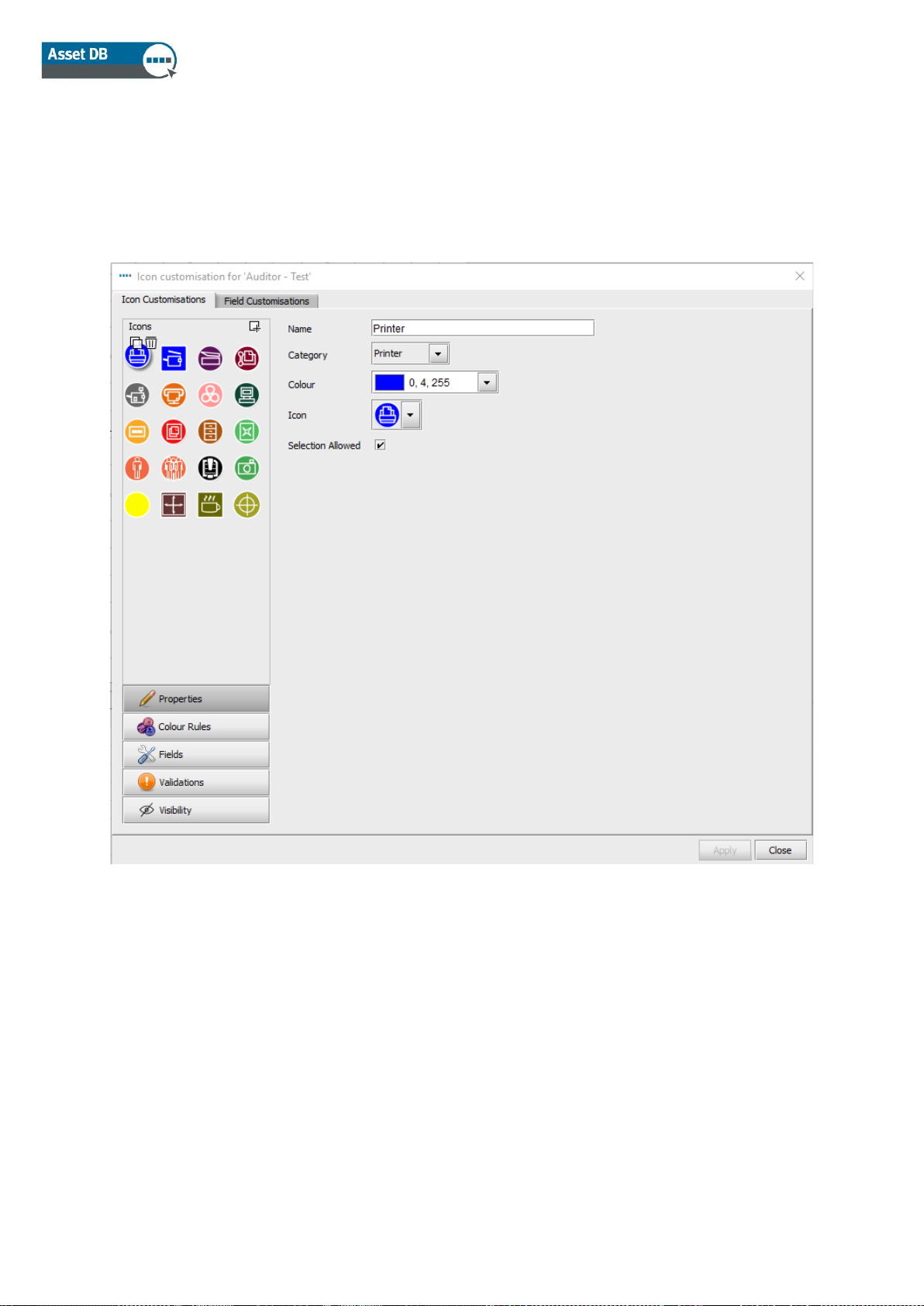
Once you have made your selection, the following dialogue will be displayed:
Figure 72. Icon customisation dialogue
19.1 Icon Customisations
The first tab, called Icon Customisations will allow you to edit the icons as they are displayed on
floor plans, define colour rules, choose which fields are displayed for each asset type, the order in
which these fields are displayed, whether the content entered into fields should be validated and
if fields should be showed as standard or whether their visibility should be subject to the data
entered into other fields.
Page 61

Auditor User Manual
- 56 - Asset DB v4.8.1
19.1.1 Icons
The Icons panel in the top left of the window allows you to edit the icon as it will be displayed by
default in the software. The icons available by default in Asset DB are shown here:
Figure 73. Available icons
To create a brand new icon, click the Add button in the top right-hand corner of the Icons
panel. This will create a brand new Icon and the properties to be decided will be shown to the
right of the Icons panel.
To select a pre-existing icon for editing, simply click on it in the Icons panel.
To create a new icon based on a pre-existing icon, select the icon you wish to copy and click the
Copy button that appears above the icon .
To delete an icon, simply click the icon to be deleted and click the Delete button that appears next
to it .
Page 62

Auditor User Manual
- 57 - Asset DB v4.8.1
19.1.2 Icon Properties
In each case, the properties of the icon selected, copied or created can be decided in the area to
the right of the Icons panel.
Figure 74. Icon properties
▪ Name – Name of Icon (e.g. Printer)
▪ Category – Asset type represented by this icon (e.g. Printer, MFD etc.)
▪ Colour – Default display colour of this icon in software and on floor plans
▪ Icon – Image to be displayed on this icon
▪ Selection allowed – Tick to permit use of the icon in the project.
Page 63

Auditor User Manual
- 58 - Asset DB v4.8.1
19.1.3 Colour Rules
The Colour Rules button allows rules to be defined to change the colour of an icon on floor plans,
depending on the data entered into one or multiple fields.
Figure 75. Colour rules view
To create a new colour rule, click the Add button above the Colour Rules panel . A new
rule will be displayed in the Colour Rules list and properties can be defined to the right of the list.
▪ Colour – the colour to be applied if criteria are met. The default colour for the selected
icon is chosen by default – this should be changed.
▪ Explanation – A brief explanation of the rule being edited can be entered here.
Rule – An explanation of the criteria to be fulfilled in order to apply the colour rule. Click
the Edit… button to define criteria. Please note rules cannot be typed into this field.
Page 64

Auditor User Manual
- 59 - Asset DB v4.8.1
Multiple colour rules can be defined for a single icon by clicking on the Add button and defining
further rules. Rules will be applied in the order in which they appear in the Colour Rules list.
Figure 76 below shows how to define criteria.
Figure 76. Edit Colour Change Criteria
Rules can be reordered by dragging them in the list and deleted by selecting the rule to be
deleted and clicking the Delete button
Figure 77. Delete rules
19.1.4 Fields
The Fields button allows for the definition of the tabs and fields displayed in the Asset Details
area (left-hand panel of Current State tab). Fields are displayed according to the groups defined
(this is explained in Section 19.2).
Select any field in the
Icon Customisation
Choice of criteria
Set multiple filters for
one field
Insert an additional
criterion
The criterion chosen will
determine whether this is
a drop down menu, a free
text field or a tick box
F and V buttons allow
you to switch between
fields and values
Page 65

Auditor User Manual
- 60 - Asset DB v4.8.1
Figure 78. Fields view
To create a new tab, click the Add button in the top right-hand corner of the Icon customisation
dialogue.
Tabs are displayed in the same way in which they will appear when mapping assets in Current
State.
Existing tabs can be renamed by clicking the Edit button, typing the desired tab name and clicking
Accept. Tabs can be deleted by clicking the Delete button.
The order in which fields are displayed on each tab can be edited by clicking on the field in
question and dragging the field to the desired position.
To insert a field not currently available in the selected tab, choose the field to be added from the
Fields list and either drag it to the desired position on the tab or click the field once in the list and
then click the Use button .
Page 66

Auditor User Manual
- 61 - Asset DB v4.8.1
To add a space between fields, click the Add gap button at the top of the dialogue . This will
add a new gap to the bottom of the fields in the selected tab, which can then be dragged to the
desired position in the same way as fields can be re-ordered.
Section headings allow you to group your fields together in the details panel. To add a section
heading to a tab, click the Add Heading button . This will add a new heading in bold font to
the bottom of the fields in the selected tab, which can then be dragged to the desired position in
the same way as fields can be re-ordered. To rename the heading, double click it, type the
desired heading and then press Enter on your keyboard.
User-added fields can be deleted at any time by selecting the desired field and clicking the Delete
button .
19.1.5 Validations
It is possible to define validation criteria for the data entered into asset fields. This is ultimately a
check to ensure that the data entered into that field is valid. If the data criteria are not met for a
field with validation, the field will be highlighted in red during data capture and a warning dialogue
box will be displayed when the changes are committed.
To set validation criteria for a field, click the Validations button in the bottom left of the window
(see Figure 79). Tabs and fields available for the selected icon will be displayed. To set validation
criteria, select the field to which the criteria are to be applied and click the Add button in the top
right-hand corner. A new validation rule will be added to the list of rules in the Validations section.
Below this, in the Criteria section the Message field is for the message to be displayed in the
warning dialogue box should the validation criteria not be met. The actual validation criteria can
be set by clicking the Edit… button.
Page 67

Auditor User Manual
- 62 - Asset DB v4.8.1
Figure 79. Validations view
19.1.6 Visibility
By clicking the Visibility button in the bottom left, dependencies can be created between fields so
they only become available for data entry if specific data is entered in another field. For example,
the Scan In Use field could be set to be visible only if the Scan Enabled field is ticked. This can
help to keep things clear for auditors and reduce data errors.
Page 68

Auditor User Manual
- 63 - Asset DB v4.8.1
Figure 80. Visibility view
To define these criteria, select the field that should be shown/hidden should certain criteria be
met and click the Edit…· button.
Criteria can then be defined that, should they not be met, will prevent the selected field being
displayed.
19.2 Field Customisations
The second tab in the Icon Customisation dialogue is the Field Customisations tab, in which new
data fields can be created for use in the tabs associated with each icon type.
On the left hand side of this tab is a list of groups, into which fields with a similar use can be
placed for easy relocation later. For example, in the Network group, fields such as DHCP
Enabled, IP Address, MAC, Subnet etc. can be found.
In order to create a new group, click the Add button above the Groups panel .
Page 69

Auditor User Manual
- 64 - Asset DB v4.8.1
Figure 81. Field Customisations tab
To the right of the Groups list is the Fields list. This list shows all fields contained in the selected
group. Fields cannot exist in more than one group at a time. If there are two fields with the same
name but in different groups, please note that the fields are different and cannot be used
interchangeably.
To add a new field to a group, click the Add button above the Fields panel . A newly created
field will be named User Field by default and will be displayed with black text in the Fields list.
Pre-defined fields will be displayed in blue text.
To edit an existing field, click to select it in the Fields list.
To the right of the Groups and Fields lists, the attributes for each field can be viewed and edited.
The following fields can be edited:
Page 70

Auditor User Manual
- 65 - Asset DB v4.8.1
▪ Name – This is the unique name of the field used by Asset DB to identify each field. The
name used here will also be used as a column header in the Asset DB Data export file.
▪ Display Name – The name to be displayed in the software to identify the field.
▪ Help text – The text to be displayed should the user click the Help button
▪ Data type – The type of field to be created. There are a number of options in this list. For
types Drop Down and Editable Drop Down, the options available in the list can be
managed in the Options list below the Data type field.
▪ Options - Where appropriate, Options can be added by clicking the Add button . Once
the option has been entered, click the Accept button . Options can be edited later
using the Edit button and deleted by clicking the Delete button . The order in which
options are displayed in a drop down list can be edited by clicking and dragging the fields
into the order desired. Below the Options, a tick box allows or blocks a Blank entry in this
field .
▪ Unique -– Requires the content of the field to be unique in the entire dataset. No
duplicates between any assets will be allowed in the project.
▪ Ignore Case – Ticking this box will mean that the field is not case sensitive.
▪ Required – Enforces the entry of data into this field. Asset changes will not be saved
unless data is entered into this field.
▪ Read-only – Disallows editing of this field in the software. Data will only be able to be
entered into this field via data import from an external source. Manual changes will be
disallowed.
▪ No-copy – Ticking this box will ensure that the contents of this field are not copied when
an asset is copied in its entirety using the copy and paste functionality.
▪ Use in Solution Design – When this box is ticked, the selected field is carried through to
the future state icon set. This option will be enabled for all fields that meet the following
criteria:
o The field is not already present in the Asset DB default set of fields for Future
State.
o The field is not a meter reading or gallery field.
o The field is not populated by volume generation on the project.
▪ Volume Transfer: This option will be greyed out until the “Use in Solution Design” box is
ticked. Once it is available, the dropdown menu will allow you to specify how these fields
behave in the Solution. There are different choices depending on the input in “Data Type”
:
o Do nothing – The value won’t be visible in the Future State field.
o Overwrite – The source value supersedes any other value in the Solution Design
field.
o Update If Empty – The source value will be visible in the Future State if the field in
the destination is empty.
o Update If Unchecked – The source value will be shown in the Future State if the
checkbox or the option selected is different (e.g. The source value is “Yes” but the
value included in the Future State is “No” or empty. The field will show “Yes”).
o Keep Max – The source value will be shown in the Future State field if it is larger
than the destination value.
o Keep Min – The source value will be shown in the Future State field if it is smaller
than the destination value.
Page 71

Auditor User Manual
- 66 - Asset DB v4.8.1
When the box “Use in Solution Design” is selected, the field will be present and populated in the
Device Fate report.
For pre-existing fields, the Name and Data type are not editable attributes. For Drop down and
Editable Drop Down-type fields, the options are not editable.
The same restrictions are placed on user created fields once the Apply button has been clicked
after their creation. Once changes to the icon customisation set have been saved, they are no
longer editable. This restriction is enforced to ensure no data is lost, should the contents of fields
in pre-existing data-sets be incompatible with newly chosen data types.
It is strongly recommended that no changes be made to Current Project icon customisations if the
project already contains asset data. Changing icon customisations and fields can pose a risk to
existing data and can cause data to be hidden in Asset DB.
20 Importing and Exporting Backups
Backups of the data held within Asset DB can be made using the File > Export > Project menu
option. This process may take some time depending on the size of the project. The resulting file
contains all floor plans, thumbnails and data and can then be shared with other Asset DB users.
Exported projects can be imported using the Import function described in Section. Please note
that this function should only be used for opening backup project files rather than during everyday
use of projects you already have available in your version of Asset DB when the Open function
will be more appropriate.
Top tip: If you have access to the Asset DB Cloud you can back up your project data by
synchronising with the server instead (see Section 22.2).
21 Organising Projects
Asset DB allows you to delete and duplicate projects from your local PC. The facility for this is
under the File > Organise > Projects menu. You can sort, filter and search for projects in the
Projects window (see Figure 82). As seen in the figure overleaf, the column on the left is for
selecting multiple projects. You can sort any column by selecting the header.
To delete your project, highlight the project you would like to delete and click the Delete button at
the bottom of the screen to confirm. This should be done with caution and we would advise that
you export your projects and save them outside Asset DB beforehand if you think you will need to
access them again in the future. If you have an export available, you can then reimport a project
at a later date.
Page 72

Auditor User Manual
- 67 - Asset DB v4.8.1
The same process should be used to duplicate your project by highlighting the project and
selecting Duplicate3. A popup will appear for you to rename the project at this time. Give the copy
a new name or a new version to help distinguish between the copy and the original. This is a very
useful feature for creating proposed scenarios without affecting the original project.
Figure 82. Organise projects
The same process can be used to duplicate TCOs, Green Calculations, and Solutions.
3
Duplicate project functionality is not available with all licence types
Search for
Projects by
name
Select and sort
Projects
Page 73

Auditor User Manual
- 68 - Asset DB v4.8.1
22 Asset DB Cloud
An additional function within Asset DB is the ability to synchronise projects to the Asset DB Cloud
(formerly called the Enterprise Server). This has many advantages:
i. Backing up your projects
ii. Allowing other Asset DB users to share project files, based upon the permissions set on
the project by the administrator
iii. Allowing many auditors to collaborate on a single project and share data
iv. Ensuring the same latest project file is available to multiple auditors before going to site.
It is recommended that before starting work on an existing project you synchronise with the Asset
DB Cloud to ensure you are working with the latest changes.
22.1 How to connect to Asset DB Cloud
To access the Asset DB Cloud you firstly need to configure Asset DB to point to the correct
location by going to Options > General Options and clicking on the Asset DB Cloud tab. This
information should only need to be set once when accessing the server for the first time.
Figure 83. Specifying credentials if connecting securely
Page 74

Auditor User Manual
- 69 - Asset DB v4.8.1
As shown in Figure 83 and Figure 84, the following should be specified:
1. Login / Password (only if connecting securely using HTTPS).
2. Server Name – This is the host name or IP address of the server on which Asset DB
Cloud is installed. Your IT Administrator can give you this information.
3. Port – This is the port that the server will be listening on. There is no user authentication
and data sent to the server will not be encrypted.
4. Secure Port – Same as port but sends your projects securely using HTTPS.
5. Proxy Details (optional) – If you access your internet connection through a proxy server
please enter the details here.
Figure 84. Configuring connection details
22.2 Synchronising Projects
If a project is open in Asset DB, it can be synchronised to the Asset DB Cloud directly by
choosing menu option Project > Synchronise. You will be asked to confirm the synchronisation. If
you answer ‘Yes’ the currently open project will be synchronised with the server.
To download new projects or to check the status of one of the projects already on your computer,
go to File > Synchronise. You are presented with a pop-up confirming which server you are
connected to and the list of projects available to you (see Figure 85).
Page 75

Auditor User Manual
- 70 - Asset DB v4.8.1
Figure 85. Asset DB Cloud synchronisation pop-up
Additionally, this will show you for each project - its version number (as it appears in the project
details panel in your project), the permissions you have for it and its synchronisation status:
▪ Up-to-date – the client and server are both up to date
▪ Upload to Server - the client has a new project which is yet to be uploaded to the server
▪ Update Server – the client has new changes to be uploaded to an existing project on the
server
▪ Update Both – both the client and server have available updates to an existing project
▪ Update Client – the server has available new changes to be downloaded to the client
▪ Download from Server – the server has new projects which are yet to be downloaded to
the client
Below the list of projects available locally and in your group(s) on the Asset DB Cloud, there is a
search field, which allows searching on all fields displayed in the Synchronise Project window, i.e.
Project Name, update date/time and Last Updated By username.
Once you have selected a project to synchronise, you will receive a pop-up enabling you to enter
a message (see Figure 86). Then click Yes and your project will synchronise to the Asset DB
Cloud.
Figure 86. Synchronisation text message
Page 76

Auditor User Manual
- 71 - Asset DB v4.8.1
Whoever synchronises the project next can then select History in the synchronisation pop-up once
the project is selected (Figure 87) and then look at the projects history and synchronisation
messages in the pop-up that follows (Figure 88).
Figure 87. Synchronisation history option
Figure 88. Synchronisation History
Asset DB Cloud supports field level synchronisation. This means that if two auditors/consultants
have updated the same asset, changes from both computers will be merged. If the same field has
been updated then data from the last synchronisation will be sent to the server as the final value.
For each project the time at which it was last modified on the server is shown along with the login
ID of the person who made the modifications.
Page 77

Auditor User Manual
- 72 - Asset DB v4.8.1
22.3 Project Notifications
If you have entered your Asset DB Cloud credentials in the General Options, then the
symbol in the toolbar in the top right of the work space will change colour when projects that you
have recently synchronised have been updated on the server. Clicking on the button will display a
list of the projects which have been modified with details about how many changes were made to
them and when. Hovering over a list item gives you the option to clear the notification,
synchronise the project or stop watching it – you then won’t receive any more update notifications
for this project (see Figure 89).
.
Figure 89. Project notifications
Project subscription preferences can be updated by going to Options > General Options and
selecting the Project Notifications tab.
23 Deactivating your Asset DB Licence
If for any reason you need to transfer your Asset DB licence from your existing PC (i.e. you get a
new laptop) it is possible to deactivate your licence ready to be used on another machine.
To do this, go to Help > Licensing > Deactivate. You will be asked if you are sure you want to
deactivate and then you will get a pop-up containing your deactivation codes. Copy the text in the
pop-up by clicking the button, paste it into an email and send it to your dedicated support
team, explaining the type of licence you hold. You will then be sent instructions for how to
reactivate your licence on a different machine.
Note: it is advisable to make a back-up of your projects BEFORE you deactivate your licence by
synchronising them with the Asset DB Cloud. If you have any TCO and Green Analyses
associated with the projects, these should be exported by going to File > Export > …. Any
Solutions should also be exported or synchronised.
This way everything will be available to import/synchronise back into Asset DB when you
reactivate your licence on the new device.
 Loading...