

Page 1
Smart choice for power
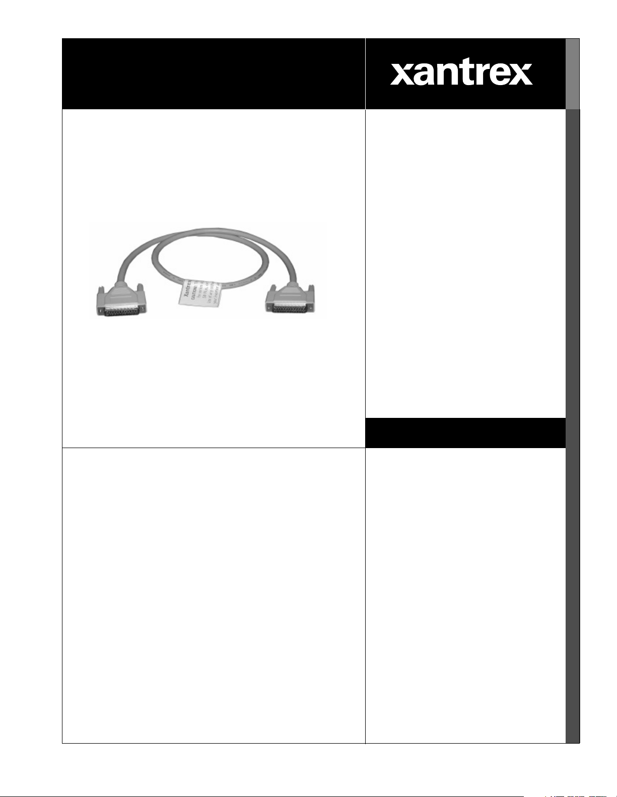
Inverter Stacking
Control Series
(ISC-S) Cable
Installation Guide
www.xantrex.com
Page 2

Page 3

Inverter Stacking Control Series (ISC-S)
Cable
Installation Guide
Page 4

About Xantrex
Xantrex Technology Inc. is a world-leading supplier of advanced power electronics and controls with products from
50 watt mobile units to one MW utility-scale system s for wind, solar, batteries , fuel cells, micr oturbines, and backup
power applications in both grid-co nnected and stand-alone systems. Xantrex products include inve rters, battery
chargers, programmable power s upplies, and varia ble speed drives that convert, supply, control, clean, and distribut e
electri cal pow er.
Trademarks
Inverter Stacking Control – Series Cable is a t rademark of Xant rex International. Xantrex is a registered trademark of
Xantrex International.
Other trademarks, registered tradem arks, and product names are the property of thei r r espective owners and are used
herein for identi fication purposes only.
Notice of Copyright
Inverter Stacking Control Series (ISC-S) Cable Installation Guide© January 2004 Xantrex International . All rights
reserved.
Disclaimer
UNLESS SPECIFICALLY AGREED TO IN WRITING, XANTREX TECHNOLOGY INC. (“XANTREX”)
(a) MAKES NO WARRANTY AS TO THE ACCURACY, SUFFICIENCY OR SUITABILITY OF ANY
TECHNICAL OR OTHER INFORMAT ION PROVIDED IN ITS MANUALS OR OTHER DOCUMENTATION.
(b) ASSUMES NO RESPONSIBILITY OR LIABILITY FOR LOSS OR DAMAGE, WHETHER DIRECT,
INDIRECT, CONSEQUENTIAL OR INCIDENTAL, WHICH MIGHT ARISE OUT OF THE USE OF SUCH
INFORMATION. THE USE OF ANY SUCH INFORMATION WILL BE ENTIRELY AT THE USER’S RISK.
Date and Revision
January 2004 Rev A
Part Number
975-0059-01-01 Rev A
Contact Information
Telephone: 1 800 670 0707 (toll free North America)
1 360 925 5097 (direct)
Fax: 1 800 994 7828 (toll free North America)
1 360 925 5143 (direct) Email: customerservice@xantrex.com Web: www. xantrex.com
Page 5

About This Guide
Purpose
The purpose of this Installation Guide is to provide explanations and procedures
for installing the Inverter Stacking Control – Series Cable and provides
information regar ding stacking two identical Sine Wave Plus inverters.
Scope
The Guide pro vides sa fety guidel ines, deta iled planni ng and setup i nformat ion for
stacking inverters, and pr ocedures for installing the ISC-S cable.
Audience
The Guide is intended for anyone who needs to insta ll series-stacked, Sine Wave
Plus inverters us ing t he Inver ter Stac king Contr ol – Ser ies Cabl e. I nstaller s sho uld
be certified techni cians or electricians.
Organization
This Guide is organized into thr ee chap t ers.
Chapter 1, “Introduction” provides information on stacking of Sine Wave Plus
inverters.
Chapter 2, “Installation” provides information on installing the DC wiring, AC
Wiring, and the ISC-S for Sine Wave Plus inverters.
Chapter 3, “Ope ration”contains information on startup and functional testing
procedures for serie s- stacked Sine Wave Plus inverters.
Warranty and Product Information is provided at the end of the Guide.
975-0059-01-01 Rev A iii
Page 6
About This Guide
Conventions Used
The following conventions are used in this guide.
WARNING
Warnings identify conditions that could result in personal injury or loss of life.
CAUTION
Cautions i dentif y co ndit ion s or pra ctic es th at cou ld r esult in damage t o t he unit or
other equipm ent.
Important:
know, but not as serious as a caution or warning.
These notes describe things which are important for you to
Abbreviations and Acronyms
The following acronyms and abbrev iations are used in this guide:
AC Alternating Current
ASC Authorized Service Center
BTS Battery Temperature Sensor
DC Direct Current
DCCB DC Conduit Box
DVM Digital Voltage Meter
GSM Generator Start Module
ISC-S cable Inverter St acking Control – Series Cable
Hz Hertz
RMA Return Material Authori zation
Va c AC Voltag e
Related Information
You can find more information about Xantrex Technology Inc. as well as its
products and services at www.xantrex.com
iv 975-0059-01-01 Rev A
Page 7
Important Safety Instructions
WARNING
This chapter contains important safety and operating instructions. Read and keep this
Installation Guide for future reference.
1. Before installing and using the ISC-S cab l e, read all instructions and
cautionary infor mation in this guide.
2. Do not expose the ISC-S cable to rain, snow , spr a y, or water.
3. Use only attachments recommended or sold by the manufa cturer . Doing
otherwise may r esult in a risk of fire, electric shoc k, or injury to persons.
4. Do not operate the ISC-S cable if it has been damaged in any way. If the ISC-
S cable is damag ed, s ee the Warranty section.
5. Do not disassemble the ISC-S cable. It contains no user-serviceable parts. See
Warranty for instructions on obtaining se rvice. Attempting to serv ice the ISC-
S cable yourself will void your wawrranty.
6. T o reduce the risk of electrical shock, disconnect both AC and DC power
from the inverters before attempting any maintenance or cleaning or working
on any circui ts connec ted to t he IS C- S c abl e. T ur ning of f th e inve rters wi ll n ot
reduce this risk.
975-0059-01-01 Rev A v
Page 8

vi
Page 9

Contents
Important Safety Instructions
1
Introduction
Stacking Inverters - - - - - - - - - - - - - - - - - - - - - - - - - - - - - - - - - - - - - - - - - - - - - - - - - - - - - - 1–2
The ISC-S Cable - - - - - - - - - - - - - - - - - - - - - - - - - - - - - - - - - - - - - - - - - - - - - - - - - - - - - - - 1–5
2
Installation
DC Wiring - - - - - - - - - - - - - - - - - - - - - - - - - - - - - - - - - - - - - - - - - - - - - - - - - - - - - - - - - - - 2–2
Battery Requirements for Series-stacked Inverters - - - - - - - - - - - - - - - - - - - - - - - - - - - - - - 2–2
Battery-Bank Configuration for Series-stacked Inverters - - - - - - - - - - - - - - - - - - - - - - - - - 2–2
Grounding Series-st acked Inverters - - - - - - - - - - - - - - - - - - - - - - - - - - - - - - - - - - - - - - - - 2–3
Connecting the Battery Bank to the Inverters - - - - - - - - - - - - - - - - - - - - - - - - - - - - - - - - - 2–4
AC Wiring - General - - - - - - - - - - - - - - - - - - - - - - - - - - - - - - - - - - - - - - - - - - - - - - - - - - - - 2–6
Inverter AC Distribution Panel (Sub-Panel) Wiring (if used) - - - - - - - - - - - - - - - - - - - - - - - 2–6
Neutral Bonding - - - - - - - - - - - - - - - - - - - - - - - - - - - - - - - - - - - - - - - - - - - - - - - - - - - - 2–7
Grounding - - - - - - - - - - - - - - - - - - - - - - - - - - - - - - - - - - - - - - - - - - - - - - - - - - - - - - - - - 2–7
AC Wiring - Specific - - - - - - - - - - - - - - - - - - - - - - - - - - - - - - - - - - - - - - - - - - - - - - - - - - - - 2–8
Off-Grid AC Wiring for Sine Wave Plus Inverters - - - - - - - - - - - - - - - - - - - - - - - - - - - - - - 2–8
On-Grid AC Wiring for Sine Wave Plus Inverters - - - - - - - - - - - - - - - - - - - - - - - - - - - - - 2–10
Generator AC Wiring to Series-s tacked Inverters - - - - - - - - - - - - - - - - - - - - - - - - - - - - - 2–12
Wiring for a 240 Vac-Only Input Source - - - - - - - - - - - - - - - - - - - - - - - - - - - - - - - - - - - 2–14
Connecting the ISC-S Cable - - - - - - - - - - - - - - - - - - - - - - - - - - - - - - - - - - - - - - - - - - - - - - 2–16
- - - - - - - - - - - - - - - - - - - - - - - - - - - - - - - - - - - - - - - - - - - -v
3
Operation
Start-up and Testing- - - - - - - - - - - - - - - - - - - - - - - - - - - - - - - - - - - - - - - - - - - - - - - - - - - - - 3–2
Setting Changes - - - - - - - - - - - - - - - - - - - - - - - - - - - - - - - - - - - - - - - - - - - - - - - - - - - - - - - 3–4
Automatic and Manual Generator Control - - - - - - - - - - - - - - - - - - - - - - - - - - - - - - - - - - - 3–4
Bulk and Float Charging Parameters - - - - - - - - - - - - - - - - - - - - - - - - - - - - - - - - - - - - - - - 3–4
Equalize Charging - - - - - - - - - - - - - - - - - - - - - - - - - - - - - - - - - - - - - - - - - - - - - - - - - - - 3–4
Automatic Generator Equalize Charging - - - - - - - - - - - - - - - - - - - - - - - - - - - - - - - - - 3–5
Manual Equalize Charging - - - - - - - - - - - - - - - - - - - - - - - - - - - - - - - - - - - - - - - - - - - 3–5
Warranty and Return Information
Index
975-0059-01-01 Rev A vii
- - - - - - - - - - - - - - - - - - - - - - - - - - - - - - - - - - - - - - - - - - - - - - - - - - - - - - - - - - - - - - - - IX–1
- - - - - - - - - - - - - - - - - - - - - - - - - - - - - - - - - - - - WA–1
Page 10

viii
Page 11

Figures
Figure 1-1 Off-Grid Applications with Series-Stacked Inverters- - - - - - - - - - - - - - - - - - - - - - - - - 1–3
Figure 1-2 On-Grid Applications with Series-stacked Inverters - - - - - - - - - - - - - - - - - - - - - - - - - 1–4
Figure 1-3 Inverter Stacking Control – Series Cable (ISC-S cabl e) - - - - - - - - - - - - - - - - - - - - - - - 1–5
Figure 2-1 Exam ple of Battery Connections for Series-stacked Inverters (24 Vdc shown) - - - - - - - 2–2
Figure 2-2 DC Grounding of Serie s-stacked Inverters - - - - - - - - - - - - - - - - - - - - - - - - - - - - - - - 2–3
Figure 2-3 DC Connections for Dual Inverters, Series-stacked- - - - - - - - - - - - - - - - - - - - - - - - - - 2–5
Figure 2-4 AC W iri n g for Se ri es-s tack ed SW Pl u s Inverters Off Grid - - - - - - - - - - - - - - - - - - - - - 2–9
Figure 2-5 AC W iri n g for Se ri es-s tack ed SW Pl u s Inverters OnGrid - - - - - - - - - - - - - - - - - - - - 2–11
Figure 2-6 Generator Wiring to Series-stacked SW Plus Inverters - - - - - - - - - - - - - - - - - - - - - - 2–13
Figure 2-7 AC Wiring for a 240 Vac-Only Input Source- - - - - - - - - - - - - - - - - - - - - - - - - - - - - 2–15
Figure 2-8 The 25-pin D-conne ctor on the ISC-S Cable - - - - - - - - - - - - - - - - - - - - - - - - - - - - - 2–16
Figure 2-9 Stacking Port Locations on SW Plus Inverters - - - - - - - - - - - - - - - - - - - - - - - - - - - - 2–16
Figure 2-10 The ISC-S Cable Connected to Dual Sine Wave Plus Inverters- - - - - - - - - - - - - - - - - 2–17
Figure 3-1 Testpoints for Confirming Voltages - - - - - - - - - - - - - - - - - - - - - - - - - - - - - - - - - - - - 3–3
975-0059-01-01 Rev A ix
Page 12

x
Page 13

1
Introduction
Chapter 1, “Introduction” provides information on stacking of Sine
Wave Plus inverters.
The following topics are covered in this chapter.
For this topic: See:
“Stacking Inverters” page 1–2
“The ISC-S Cable” page 1–5
Page 14

Introduction
Stacking Inverters
Two identical, series-stack ed, inv erters can be conne cted toget h er for the
following purposes.
• The voltage output of a single inver ter is insufficient to powe r the 240 Vac
loads attached to the system;
• Multi-wire branch circu its exists in the current str ucture . Please see Appendix
F, “Multi-wire Branch Circuit Wiring”, in the Sine Wave Plus Owner’s
Manual for additional information.
Important:
configurations. In other words, you can use two SW Plus 2548 inverters, or two
SW Plus 4048 inverters. You cannot stack a SW P lus 2548 with a SW Plus 4048.
Different types of inverters cannot be intermixed in a stacking configurati on.
Models with 230 Vac, 50 Hz, output cannot be series-stack ed.
Stacking inve rters in a “series” configuration can double the output voltage at the
same current level as an individual inverter.
Series-sta cki n g conn ect s the ne utr al output s of each inve rt er tog eth er an d ena b les
the inverters to synchronize their hot outputs to be 180 degrees out-of-phase with
each other. This maintains the wattage output at the rated level, but doubl es the
voltage output avail able, thereby allowing 240 Vac loads to be supported by the
system.
Example: T wo series-st acked, Sine Wave Plus 4024 Vac inverters can run both
120 Vac and 240 Vac loads at 33 amps continuous output.
Stacking inverters in a series configuration requires the use of the Inverter
Stacking Control- Series (ISC-S) Cable.
Inverter types and models must be identical for stacking
1–2 975-0059-01-01 Rev A
Page 15
Stacking Inverters
Figure 1-1
975-0059-01-01 Rev A 1–3
Off-Grid Applications with Series-Stacked Inverters
Page 16

Introduction
Figure 1-2
1–4 975-0059-01-01 Rev A
On-Grid Applications with Series-stacked Inverters
Page 17

The ISC-S Cable
The ISC-S Cable
Required accessory cable
Stacking two i dentic al inve rters requi res the use of the Inverte r St ackin g Contro l –
Series Cable (ISC-S cable). The ISC -S cab l e is a special cable specifically
designed for series- stacking two identical inverters. It consists of one 36-inch
stacking control cable with two 25-pin D connectors. It connects to the “Stacking
Ports” on the respective inverters and allows the AC output of two (identical)
inverters to provide both 120 and 240 Vac, 60 Hz.
CAUTION: Damage to Equipment
Do not use a standard c omputer cable in place of the ISC-S cabl e cable. This ISCS cable is custom made for Xantrex to allow series-stacking with the SW Plus
Inverter/char ger. Look for the l abel as shown i n Figure 1-3 to prop erly ide ntify t he
cable.
Use of any other cable may damage your inverters and will not be covered by
Warranty/ Repair.
Xantrex ISC-S Cable
CAUTION: This cable is desi gned
for series stacking of the SW,
SW Plus, or PS inverters only.
Use of any other cabl e may da mage
your inverte r and voi d it’s warranty.
Figure 1-3
975-0059-01-01 Rev A 1–5
Inverter Stacking Control – Series Cable (ISC-S cable)
Page 18

What it does
What it does not do
The ISC-S cable provides communication between the two stacked inverters for two
purposes.
• It provides synchroniz ation information for inverting and charging.
• It provides a method for one inverter detecting an error condition to send a shutdown command to the other inverter, to prevent a 240Vac load from only receiving
one leg of power.
The ISC-S cable does not allow programming or acce ss to the display from one inverter
to the other. If there are changes to the def ault setting necessary, each inverter must be
programmed separately. This includes sele cting “On” in the “On/Off” menu.
1–6
Page 19

2
Installation
Chapter 2, “Installation” provides information on installing the
DC wiring, AC Wiring, and the ISC-S for Sine Wave Plus inverters.
The following topics are covered in this chapter.
For this topic: See:
“DC Wiring” page 2–2
“AC Wi ring - Gene ral” page 2–6
“AC Wi ring - S pecific” page 2–8
“Connecti ng the ISC-S Cable” page 2–16
Page 20

Installation
w
DC Wiring
The success of series-sta c ked, inverter systems is dependent on the quality and
maintenance of the DC conn ections. Stacked inverter sets are far less forgiving to
long, undersized, une ven, and/or poor connections than are single inverters.
Battery Requirements for Series-stacked Inverters
When inver ters are “s tack ed” t h ey mu st o perat e from a common bat te ry bank . In
other words, the DC negative of one inverter must be common with the second
inverter and likewis e for the DC posit ive.
For example:
If you have eight 6-volt batteries in a 24-volt configuration, they would be
arranged in two rows of four batteries (see Appendix C of the Sine Wave Plus
Owner’s Manual for diagrams of v arious a rrange ments). The negativ e ends of
the two “strings” of batteries must be jumpered together to become common
with each other. Likewise, the positive ends of the two “strings” must also be
jumpere d together so that they are also common with each other.
Battery-Bank Configuration for Series-stacked Inverters
When using inverters in a stacked conf iguration, the same battery bank must be
used for both inve rt ers. To ensure even charg ing of the batteries, each inve rt er
must be connected to both strings (i .e ., positive cable to string two, and negative
cable to str ing one for inverter 1, and positive cable to string one and negative
cable to str ing two for inverter 2) as shown in Fig ure 2-1 . In other words, a
separate positive (+) and nega tive (–) cable pair is requi red for eac h inverter in t he
series-stac ked confi guration. This means the re will be four batter y cables from the
stacked inverters to the battery bank.
Refer to the Owner’s Manual for the Sine Wave Plus to determine the correct size
and length of cable required.
12 Volt
Battery
200 Ah
12 Volt
Battery
200 Ah
DC conduit for
L1 In verter
+–
Series String 1
24 Vdc/200 Ah
Series String 2
24 Vdc/200 Ah
Series-strings
ired in Parallel
24 Vdc / 40 0 Ah
DC conduit for
L2 In ve rter
– +
12 Volt
Battery
200 Ah
– +
12 Volt
Battery
200 Ah
– +
Figure 2-1
Example of Battery Connections for Series-stacked Inverters
(24 Vdc shown)
2–2 975-0059-01-01 Rev A
Page 21

Grounding Series-stacked Inverters
d
s
To ground series-stacked inverters:
1. Connect the ground bond in the DC disconnect betwe en the inverters and the
batteries to the primary gr ounding electrode, in accordance with loc al and
national elect rical codes.
2. Connect an appropriately sized ground wire from the chassis bondin g ground
lug on the L1 inverter DC end to the ground bond inside the DC disconnect.
3. Connect a second appropriat ely sized ground wire from the chassis bonding
ground lug on the L2 inverter DC end to a different terminal in the ground
bond inside the DC disconnect.
xantrex
Sine Wave Plus Inverter/Charger
L1 Inverter
Chassis Bonding
Ground Lug
xantrex
INV
GEN
ON/OFF
MENU
01A Inverter
OFF SRCH ON CHG
MENU
MENU
HEADINGS
ITEMS
DC Wiring
–
Invert er Cont r ol M odul e
+
GRID TIE
ERRORBULKAC1
INVERTAC2 FLOATSTATUS
SET
POINTS
Reset DefaultsContrast
xantrex
Figure 2-2
–
Invert er Cont r ol M odul e
xantrex
01A Inverter
INV
GEN
ON/OFF
Sine Wave Plus Inverter/Charger
MENU
L2 Inverter
Chassis Bonding
OFF SRCH ON CHG
MENU
MENU
HEADINGS
ITEMS
+
GRID TIE
ERRORBULKAC1
INVERTAC2 FLOATSTATUS
SET
POINTS
Reset DefaultsContrast
DC
DISCONNECT
SHUNT &
NEGATIVE BUS
ON
ON
Ground Lug
OFFONOFF
OFF
GROUND
DC Grounding of Series-stacked Inverters
To primary
Earth/groun
connection
975-0059-01-01 Rev A 2–3
Page 22

Installation
Connecting the Battery Bank to the Inverters
The following instruc tions are illustrated in Figure 2-3.
To connect the battery (or battery bank) to the inverters:
1. Connect POSITIVE cables: a) one cable from the battery POSITIVE terminal to a circuit breaker in the
DC disconnect (torque to manufacturer’s recommendations). The DC
disconnect should be loca ted as close to the batteries as possible.
b) a second cable from the same battery POSITI VE termin al to another
circuit breaker in the DC disconnec t.
c) a third cable from the first circuit breaker in the DC disconnect to the
L2 inverter POSITIVE (+) terminal.
d) a fourth cable from the second DC disconnect to the L1 inverter
POSITIVE (+) terminal.
2. Connect NEGATIVE cables: a) one cable from the same battery NEGATIVE terminal (torque to
manufacturer’s recommendations) to the ground bond in the DC
disconnect.
b) a second cable from the same battery NEGATIVE terminal (torque to
manufacturer’s recommendations) to the ground bond in the DC disconnect.
c) a third cable from the ground bo nd in the DC dis conn ect to t he L2 in verte r
NEGATIVE (–) terminal.
d) a fourth cable from the ground bond in the DC disconnect to the
L1 inverter NEGATIVE (–) terminal.
3. Ensur e the correct polarity of the cab le s with a D C volt me te r (D VM).
4. Use an insulated 1/2 inch wrench or socket to tighten the 5/16 SAE nuts to
10-15 foot/lb for each inverter input terminal.
5. After tightening the connections on the batteries, apply antioxidant paste to
the battery ter minals, if desire d. Do not apply antiox idant paste to th e inverte r
terminals.
6. Install th e battery terminal covers (if used)—red for positive, black for
negative—over the inverter DC terminals and secure with the screws and
washers provided.
2–4 975-0059-01-01 Rev A
Page 23

d
s
xantrex
xantrex
Sine Wave P l us I nverter/Ch arger
L1 Inverter
Chassis Bonding
Ground Lug
Si ne Wave Pl us I nverter/C harger
L2 Inverter
xantr ex
INV
GEN
ON/OFF
MENU
xantre x
INV
GEN
ON/OFF
MENU
01A Inverter
OFF SRCH ON CHG
MENU
MENU
HEADINGS
ITEMS
01A Inverter
OFF SRCH ON CHG
MENU
MENU
HEADING S
ITEMS
SET
POINTS
POINT S
SET
Inverter Con t r ol M odu l e
GRID TIE
INVERT AC 2 FLOAT STATUS
Reset DefaultsContrast
Inver ter Control Module
GRID TIE
INVERT AC2 FLOAT STATU S
Reset DefaultsContrast
DC Wiring
–
+
ERRORBULKAC1
2d
–
+
ERRORBULKAC1
2c
DC
DISCONNECT
SHUNT &
NEGATIVE BUS
Chassis Bonding
Ground Lug
Series-strings
wired in Parallel
24 Vdc/400 Ah
DC Co ndui t
L2 Inverter
1c
1d
ON
OFFONOFF
1a
2a
– +
12 Volt
Battery
200 Ah
– +
12 Volt
Battery
200 Ah
GROUND
1b
– +
12 Volt
Battery
200 Ah
12 Volt
Battery
200 Ah
Neutral-to-Ground
Bond
2b
DC Conduit for
L1 Inverter
Series String 1
24 Vd c/200 Ah
Series String 2
+–
24 Vdc/ 200 Ah
To primary
Earth/groun
connection
Figure 2-3
DC Connections for Dual Inverters, Series-stacked
975-0059-01-01 Rev A 2–5
Page 24

Installation
AC Wiring - General
Be sure to use the recommended wir e and disc onnect size as recommended in the
Owner’s Manual for the Sine Wave Plus Inverter.
WARNING
Before connecting any AC wiring, ensure tha t there is no DC energy accessible by the
inverter by opening the DC disconnect switch(es).
Inverter AC Distribution Panel (Sub-Panel) Wiring (if used)
An Inverter AC Distribution Panel (referred to here as the inverter panel) and AC
conduit must be installed befor e AC output wiring is connected to the dual
inverters. The inverter panel is a sub-panel to the main utility panel.
Install the Inverter AC Distribution Panel and conduit as follows:
1. Determine the locatio n for the Inve rter AC Distribution Panel (i.e., the
sub-panel) and insta ll it according to the manufacturer’s directions.
2. Install an AC conduit to the invert er panel and the inverter.
3. Determine which circuits the inve rter will power and install the appropriate
circuit breakers into the inverter panel.
4. For On-Grid sy stems, r emove wi res for ci rcuit s to be backed up fr om the m ain
utility panel and insta ll then in the new inverter (sub) panel.
5. Install a double pole 60-amp maximum (disc onne ct) main circuit breaker in
the inverter panel: one for each leg of the ci rcuit for L1 and L2.
6. Verify that under no circumstances can utility power or generator power
energize the inve rter p anel direc tly w hile the inv ert er als o energizes the
inverter panel.
WARNING: Shock Hazard
Verify that only one neutral/ground bond exists in the system. Having more than one
neutral to ground bond in a s ystem may create a shock hazard and cause some sensitive
equipment to mal function.
On-Grid systems always have a ground-to-neutr al bond provided by the utility meter or
service entra nce, therefore do not need a ground-to-neutral bond made in the inverter
panel. Remove it if present in the sub-panel.
2–6 975-0059-01-01 Rev A
Page 25

Neutral Bonding
Grounding
AC Wiring - General
The HOT output of each inverter provides 120 Vac to neutral. The voltage
between the HOT ou tputs from the L1 and L2 inverter is 240 Vac when the ISC-S
cable is use d.
When using a series-stacked, inverter configuration, it is important to provide a
neutral bond between both inver ters. Accomplish this bond by establi shing an
inverter -to-inverter neutral bond.
Keep the neut ral bonding jumper as short as possible to provide a better AC “zero
volt” reference for each inverter to measure AC voltages from, as well as saving
on wire. The neutral bond wire must be the same gauge as the other AC wires
attached to the invert er.
Ensure all c omponents are grounded properly for safety a nd for code-compliance.
WARNING: Hazardous Voltage
When stacking inverters, ensure the chassis of each invert er is connected to the same
common ground (i.e., in the utilit y or inverter panels); otherwise a hazardous voltage may
be present between the chasses.
975-0059-01-01 Rev A 2–7
Page 26

Installation
AC Wiring - Specific
The following AC connections are spe cific to installing the Sine Wave Plus
Inverter/chargers in a series-stacked configuration for off-grid and on-grid
applications.
Off-Grid AC Wiring for Sine Wave Plus Inverters
The following steps are illustrated in Figure 2-4.
To connect the AC wi ring fo r an off -g rid a ppl ica ti on us i ng Si ne Wave Plus Inverters:
Grounding 1. Connect G
a) from the primary earth/ground to the AC distribution panel,
b) from the L1 inverter AC ground bar to the inverter panel ground bar,
c) from the L2 inverter AC ground bar to the inverter panel ground bar.
Neutral Bonds 2. Connect N
a) from the N
b) from the L1 inverter N
c) from the L2 invert er N
Inverter to AC Distribution Pane l
3. Connect a HOT wire: a) (black) from the L 1 invert er AC H
b) (red) from the L2 inverter AC H
4. T orque all inverter terminal block connections to 25 inch-pounds.
ROUND (green) wires:
EUTRAL (wh ite ) wire s :
EUTRAL bus in the inverter panel, to the ground bar in the
inverter panel, (Neutral-to-Ground Bond),
EUTRAL OUT terminal, to the L2 inverter NEUTRAL
2 terminal. (Inverter-to-inverter neutral bond),
EUTRAL OUT terminal to the inverter panel
N
EUTRAL bus. (Common neutral bond in inverter panel).
panel L1 terminal,
panel L2 terminal.
OT OUTPUT (120 Vac) to the inverter
OT OUTPUT (120 Vac) to the inverter
2–8 975-0059-01-01 Rev A
Page 27

2)
LEGEND
1)
T
GROUND
NEUTRAL
HOT L1
HOT L2
AC
GROUND
BAR
(inside)
1b
2b
AC Wiring - Specific
Sine Wave Plus
Inverter/Charger
AC TERMINAL
BLOCK
INV OUT
NEUTRAL OUT
NEUTRAL 2
NEUTRAL 1
AC1 GRID
AC2 GEN
3a
Sine Wave Plus
Inverter/Charger
(L
AC
GROUND
BAR
(inside)
AC TERMINAL
BLOCK
(L
AC Distribution Panel
(Inverter Panel)
120/240 Vac
L1 L2
3a
3b
NEUTRAL
2a
1c
2c
NEUTRAL 1
AC1 GRID
AC2 GEN
INV OUT
NEUTRAL OUT
NEUTRAL 2
3b
o AC Loads
1a
Figure 2-4
AC Wiring for Series-stacked SW Plus Inverters Off Grid
GROUND
To primary
Earth/ground
connections
To AC Loads
1b
1c
NEUTRAL/
GROUND BOND
975-0059-01-01 Rev A 2–9
Page 28

Installation
On-Grid AC Wiring for Sine Wave Plus Inverters
Prepare the AC wiring as follows for an on-grid application using series-stacked,
Sine Wave Plus Inverter/chargers. The following steps are illustrated in
Figure 2-5.
Grounding 1. Connect G
a) from the primary earth/ground to the main utility panel,
b) from the main utility panel to the AC distribution panel (Sub-panel),
c) from the L1 inverter AC ground bar to the utility panel ground bar,
d) from the L2 inverter AC ground bar to the utility panel ground bar.
Neutral Bonds 2. Connect N
a) from the Neutral bus in the utility panel to the ground bar in the utility
panel. (Neutra l-to-ground bond),
b) from the L 1 inve rt er NEUTRAL OUT terminal to the L2 inverter
NEUTRAL 2 terminal (Interter-to-inverter neutral bond),
c) from the L1 invert er N
neutral bus (Common neutral bond in uti lity panel),
d) from the L2 inverter N
neutral bus (Common neutral bond in sub-pa nel),
Inverter to AC Distribution Pane l
3. Connect H
a) (black) from the L 1 invert er AC H
panel L1 terminal.
b) (red) from the L2 inverter AC H
panel L2 terminal.
Inverter to Utility Panel
4. Connect H
a) (black) from the utility panel HOT L1 terminal to the L1 inverter’s AC1
GRID terminal.
b) (red) from the utility panel HOT L2 terminal to the L2 inverter’s AC1
GRID terminal.
5. T orque all inverter terminal block connections to 25 inch-pounds.
ROUND (green) wires:
EUTRAL (wh ite ) wire s :
1
EUTRAL OUT terminal to the utility or utility panel
EUTRAL OUT terminal to the AC dist ribution panel
OT wires:
OT OUTPUT (120 Vac) to the inverter
OT OUTPUT (120 Vac) to the inverter
OT wires:
1.This connect ion may alrea dy exis t from the origina l insta llat ion of AC service to the
building.
2–10 975-0059-01-01 Rev A
Page 29

AC Wiring - Specific
1a 1b
To primary
Earth/ground
connections
4a
4b
Main Utility Panel
120/240 Vac Panel
L1 L2
L1
L2
GROUND
1d
NEUTRAL
2a
1c
NEUTRAL/GROUND
BOND
2c
AC
GROUND
BAR
(inside)
4a
Sine Wave Plus
Inverter/Charger
AC TERMINAL
BLOCK
NEUTRAL OUT
NEUTRAL 2
NEUTRAL 1
AC1 GRID
AC2 GEN
3a
LEGEND
GROUND
NEUTRAL
HOT L1
HOT L2
(L1)
INV OUT
AC Distribution Panel
To AC Loads
(Sub-panel)
120/240 V ac
L1
GROUND
3a
1b
3b
NEUTRAL
2b
AC
GROUND
BAR
(inside)
L2
1d
Sine W ave Plus
Inverter/Charger
AC TERMINAL
BLOCK
NEUTRAL OU T
NEUTRAL 2
NEUTRAL 1
AC1 GRID
AC2 GEN
4b
3b
INV OUT
(L2)
2d
To AC Loads
Figure 2-5
AC Wiring for Series-stacked SW Plus Inverters OnGrid
975-0059-01-01 Rev A 2–11
Page 30

Installation
Generator AC Wiring to Series-stacked Inverters
The following wiring diagrams show the AC wiring from an AC generator to the
inverters.
The following procedures a re illustrated in Figure 2-6.
With a generator disconnect switch
Important:
Ensure that a n inverter-to-inverter neutral bond is in place
before proceeding wit h this procedure.
To install the AC wiring from a generator with a (GDS):
1. Connect G
a) from the generator G
ROUND (green) wires:
ROUND to the generator disconnect switch G ROUND
terminal,
b) from the ge nerator disconnect switch G
ROUND to the AC Ground bar in
the utility panel*.
2. Connect N
a) from the generator N
EUTRAL (wh ite ) wire s :
EUTRAL to the GDS NEUTRAL terminal,
b) from the ge nerator disconnect switch NEUTRAL to the L1 INVERTER
N
EUTRAL 2terminal.
3. Connect H
a) from the genera tor L 1 G
OT (L1- black) w ires :
EN HOT OUT to the GDS L1 HOT terminal,
b) from the generator discon nect switch L1 HOT to t he L1 INVERTER AC2
G
EN terminal.
4. Connect H
a) from the genera tor L 2 H
OT (L2 - red) wires:
L2 H
OT terminal,
OT OUT to the gene rator disconnect switch
b) from the generator discon nect switch L2 HOT to t he L2 INVERTER AC2
G
EN terminal.
5. T orque all inverter terminal block connections to 25 inch-pounds.
Important:
go to the Main Utility Panel should be routed to the AD Distribution Panel instead.
2–12 975-0059-01-01 Rev A
*If this is an off-grid installat ion, then all connections that would normally
Page 31

To primary
Earth/ground
connections
1b
L1
L2
120/2 40 Vac P anel
L1 L2
GROUND
3b
4b
Main Util ity
Panel
NEUTRAL
2b
NEUTRAL/GROUND
BOND
AC
GROUND
BAR
(inside)
Sine Wave Plus
Inverter /Charger
AC TE RMINAL
BLOCK
INV OUT
NEUTRAL OUT
NEUTRAL 2
NEUTRAL 1
AC1 GRID
AC2 GEN
AC Wiring - Specific
LEGEND
GROUND
NEUTRAL
HOT L1
HOT L2
(L1)
Generator
Disconnect
Switch
(optional)
Generator
120/2 40 Vac
AC D i stribution Panel
(Sub-panel)
120/240 Vac
To AC Loads
N
G
L1 L2
3a
1a
GROUND NEUT RAL
GEN HOT OUT
2a
4a
L1 L2
L1 L2
GROUND
NEUTRAL
AC
GROUND
BAR
(inside)
Sine W av e Pl u s
Inverter/Charger
AC TERMINAL
BLOCK
INV OUT
NEUTRAL OUT
NEUTRAL 2
NEUTRAL 1
AC1 GRID
AC2 GEN
To AC Loads
(L2)
Figure 2-6
Generator Wiring to Series-stacked SW Plus Inverters
975-0059-01-01 Rev A 2–13
Page 32

Installation
Wiring for a 240 Vac-Only Input Source
A 240 Vac source does not allow for the connection to the input of a 120 Vac
inverter as no neutral li ne is supplied from the utility or generator. In order to use
stacked inverters, a neutral line must be added by using a center-ta pped
autotransformer (such as a T240) on the inverter’s input. This will cr eate the
necessary neutral retur n line for the inverters, and half the volta ge for each
inverter to 120 Vac. The output of the inverte r supplies both 120 and 240 Vac to
the loads.
The ISC-S cable and autotransformer (capable of handling the system’s power
requirements) a re required in this configuration..
To wire the inverters for a 240-Vac only input source:
1. Run G
ROUND wires (green):
a) from the AC Distribution Panel to the primary earth/ground connection.
b) from the generator ground to the AC Distribution Panel ground.
c) fro m the grou nd term in al in t he Aut o tran s f o r mer to t he AC Distr ibution
Panel.
d) from the AC Distribution Panel to the Ground ba r in the L1 inverter.
e) from the AC Distribution Pane l to the Ground ba r in the L2 inverter.
2. Run NEUTRAL wires (white): a) from the center-tapped neutral connection in the autotransformer to the
NEUTRAL 1 terminal in the L1 inverter .
b) from the center-tapped neutral connection in the autotransformer to the
NEUTRAL 1 terminal in the L2 inverter.
c) from the NEUTRAL OUT on the L1 inverter to the NEUTRAL 2
terminal on the L2 inverter.
d) from the Neutral OUT on the L2 inverter to the Neutral terminal in the
AC Distribution Panel.
3. Run HOT wires: a) (black) from the L1 Output in the generator to the L1 terminal in the
Autotransformer.
b) (black) from the L1 output terminal in the Autotransformer to the
AC2 GEN terminal in the L1 inverter.
c) (black) from the INV OUT terminal in the L1 inverter to the L1 input
terminal in the AC Distribution P anel.
d) (red) from the L2 Output in the generator to the L2 termina l in the
Autotransformer.
e) (red) from the L2 output t erminal in the Aut otran sformer to the AC2 GEN
terminal in the L2 inver ter.
f) (red) from the INV OUT terminal in the L2 inverter to the L2 input
terminal in the AC Distribution P anel.
4. T orque all inverter terminal block connections to 25 inch-pounds.
2–14 975-0059-01-01 Rev A
Page 33

AC Wiring - Specific
2)
)
LEGEND
GROUND
NEUTRAL
HOT L1
HOT L2
1b
GROUND
GEN HOT
OUT
L1
L2
Generator
240 Vac - ONLY
AC Distribution Panel
(Inverter Panel)
120/240 Vac
Auto-transformer
(with center-tapped neutral-out)
3a
3d
1c
L1
Neutral
Ground
3c
L1
L2
3f
3b
3e
L2
NEUTRAL
2b
1d
AC
GROUND
BAR
(inside)
1e
Sine Wave P lus
Inverter/Charger
AC
GROUND
BAR
(inside)
2c
AC1 GRID
Sine Wave Pl us
Inverter/Charger
AC TERMINAL
AC1 GRID
AC TERMINAL
BLOCK
NEUTRAL 2
NEUTRAL 1
AC2 GEN
2a
BLOCK
NEUTRAL OUT
NEUTRAL 2
NEUTRAL 1
AC2 GEN
INV OUT
NEUTRAL OUT
3c
(L
INV OUT
3f
(L1
2d
To AC Loads
GROUND
To AC Loads
1d
1a
1c
NEUTRAL/GROUND
BOND
1b
To primary Earth/
ground connections
Figure 2-7
AC Wiring for a 240 Vac-Only Input Source
975-0059-01-01 Rev A 2–15
Page 34

Installation
Connecting the ISC-S Cable
The ISC-S Cable connects to the Stacking Port on the AC e nd of the Sine Wave
Plus Inverter/cha rger. The Stacking Port is a 25-pin receptacle for the 25-pin
D-connector on the ISC-S Cable. Once the connector is in place, it is secured by
two screws on the sides of the conne ctor.
Align the head of the connector
with the Stacking Port on the
inverter and insert into the port.
Figure 2-8
The 25-pin D-connector on the ISC-S Cable
Gently tighten t hese two screws to
secure in place.
Stacking Por t
Figure 2-9
Stacking Port Locations on SW Plus Inverters
To connect the ISC-S cable:
1. Orient the 25- pin D-connector to align with the Stacking Port on the Inverter
and gently press the connect or into the port. Use caution not to bend the pins
inside the connector head.
2. Tight en the screws on the connector to secure the cable to the port.
3. Connect the other end of the ISC- S cab le to the second inverter’s Stacking
Port as instructed in step 1 and 2.
2–16 975-0059-01-01 Rev A
Page 35

Connecting the ISC-S Cable
Connect one end of ISC-S
Cable to the Stacking Por t
of the L1 inverter.
Figure 2-10
Connect the other end of
ISC-S Cable to the Stacking
Port of the L2 inverter.
The ISC-S Cable Connected to Dual Sine Wave Plus Inverters
CAUTION; Damage to Loads
Until the units are tested, do not conn ec t any loads to the inverters. Proceed to the next
chapter for Start up and Functional Testing Procedures.
975-0059-01-01 Rev A 2–17
Page 36

2–18
Page 37

3
Operation
Chapter 3, “Operation”contains information on startup and functional
testing procedures for series-stacked Sine Wave Plus inverters.
The following topics are covered in this chapter.
For this topic: See:
“Start-up and Tes ting” page 3–2
“Setting Changes” page 3–4
Page 38

Operation
Start-up and Testing
Stacked invert ers must operate togethe r in order to provide the 120/24 0 Vac to the
loads. The ISC-S cable ensures the output from each inverter is 180 degrees
out-of-phase for operating 240 Vac loads.
To start up and test the inverters:
1. Ensure the circuit breakers on all AC sources (utility or generator, if any)
feeding the in vert ers are O FF.
2. Ensure the circuit breake rs in the AC distribution panel (sub-panel) are OFF.
3. Switch ON both inverters. The inverters should be providing 120/240 Vac to
the AC distribution panel.
4. In the AC distribution panel, use an AC voltmeter and measure the voltage
between the L1 (H
120 Vac (± 3%). See Figure 3-1 for te stpoint locations.
5. In the AC distribution panel, use an AC voltmeter and measure the voltage
between the L2 (H
120 Vac (± 3%). See Figure 3-1 for testpoint locations.
OT) terminal and the neutral bus. This voltage should be
OT) terminal and the neutral bus. This voltage should be
6. In the AC distribution panel, measure the voltage between the L1 (H
OT) and
L2 (HOT) terminals. This voltage should be 240 Vac (± 3%). See Figure 3-1
for testpoint locations.
7. If all voltages/tests are correct, a) switch on the circuit breakers in the AC distribution panel , and
b) switch on the generator or util ity c i r cuit breakers feeding the inverters.
8. Verify the inverters are charging the batteries and powering the AC distribution pan el.
9. Switch both inverter s OFF and open the circuit breakers to ensure al l AC and
DC po wer is tu r n ed OFF to th e i nver t e rs.
10. Replace all covers and pa nels on the inverters and sub-panel.
11. The series-stacke d inve rter system is now tested and ready for use.
If the inverters are not oper ating properly, please refe r to the Sine Wave Plus
Operator’s Manua l for setup and troubleshooting info rmation.
3–2 975-0059-01-01 Rev A
Page 39

Start-up and Testing
c
LEGEND
GROUND
NEUTRAL
HOT L1
HOT L2
AC Distribution Panel
To 120 Vac
Loads
(Sub-panel)
120/240 Vac
L1 L2
4
GROUND
To L1 Inverter
6
NEUTRAL
5
To L2 Inverter
To L2 Inverter
To 240 V a
Loads
To Main Utility
Panel Groun d
Figure 3-1
975-0059-01-01 Rev A 3–3
Testpoints for Confirming Voltages
Page 40

Operation
Setting Changes
When operating a S ine Wave Plus in a series-stacked configuration, the following
settings must be changed for prope r operation.
See the Owner’s Manual for the Sine Wave Plus for detailed instructions on
accessing and c hanging the settings using the Inverter Control M odule (ICM) on
the inverter.
Automatic and Manual Generator Control
When multip le inv er te rs are use d with a ge n era tor, the invert er con n ected to the
generator via the Generator Start Module (GSM) is designated as the “generator
controlling” inve rter. The most efficient bat tery charging is achieved by setting
the charging par ameters of each inverter slightl y differently.
Bulk and Float Charging Parameters
Change the Bulk and Float Charging settin gs as follows:
• Set the 12B B
• Set the 12C F
• On the non-generator-controlling inver ter (the inverter not connected to a
GSM), set the charging time for a shorter period than on the generator
controlling inverter. This is accomplishe d by setting the 12F B
AMPS to a higher setting. If the 12F BULK DONE AMPS is set to zero (0), then
the 12H MAX BULK/EQ Timer h:m should be set to a shorter time period on
the non-generator-controlling inverter.
ULK VOLTS DC to the same setting on both inverters.
LOAT VOLTS DC to the same setting on both inverters.
ULK DONE
Equalize Charging
Change the Equalize Charging settings as follows:
• Set both inverters to the same 12D E
• Set the 12G EQ V
to a shorter equalize time.
T o start an Equalize charge (manually or automatically) , se t both inverters to EQ
by scrolling to 01B EQ CHARGE ON/OFF and selecting ON.
During the equalize charge, the Bulk LED will slowly flash on each inverter,
indicating the EQ select ion has been enabled.
3–4 975-0059-01-01 Rev A
DC DONE TIMER H:M on the “generator controlli ng” inverter
QUALIZE VOLTS DC setting.
Page 41

Automatic Generator Equalize Charging
If the inve rters ar e set t o a utomaticall y c harge the b atterie s using the generator, the
equalize process will be gin during the next, automatically started, generator run
period. When the equalizing process has completed, the generator automatically
stop s a n d t he cur sor re turns to the OFF posit io n in the 01B EQ C
item on the generator-controlling inverter. The non-generator-controlling inverter
must be set from EQ to OFF from the 01B EQ CHARGE menu item or it will start
another equalize charge the next time the generator is started.
Manual Equalize Charging
If the batteries were equalized using a manually started generator or from the
utility grid, the F
complete. Set the cursor to OFF on both inverters under the 01B EQ CHARGE
menu item when the equalization process is complete.
LOAT LED illumina tes, indicating the equaliz ation process is
Setting Changes
HARGE menu
Important:
connected to the same location (battery).
If using multiple bat tery temperature sensors (BTS) ensure they are all
975-0059-01-01 Rev A 3–5
Page 42

3–6
Page 43

Warranty and Return Information
Warranty
What does this warranty cover? This Limited Warranty is provided by Xantrex Technology, Inc. ("Xantrex")
and covers defects in workmans hip and materials in your Inverter Stacking Control – Series Cable. This warran ty
period lasts for two (2) years fro m the date of purchase at the point of sale to you, the or iginal end user customer. You
require proof of purchas e to make warra nty claims.
This Limited Warranty is transfer able to subsequent owner s but only for the unexpired portion of the Warranty
Period.Subsequent owners also require proof of purc hase.
What will Xantrex do?
Xantrex will, at its option, repair or replace the defective product fr ee of charge, provided that you notify Xantrex of
the product defect with in the Warranty Period, and prov ide d that Xant rex throu gh inspe ction e stab lishe s the existenc e
of such a defect and that it is covere d by this Limited Warranty.
Xantrex will, at its option, use new and/or reconditioned parts in performing warranty repair and building
replacement products. Xantrex reserves the right to use parts or products of original or improved des ign in the repair
or replaceme nt. If Xantrex repairs or replaces a product, its warranty continues for the remaining portion of the
original Warranty Period or 90 days from the date of the re turn shipment to the custom er, whichever is greater. All
replaced products and all parts removed from repaired products become the property of Xantrex.
Xantrex covers both parts and labor necess ary to repair the product, and return shipment to the cus tomer via a
Xantrex-selec ted non-expedited surface freight wit hin the contiguous United States and Canada. Alaska and Hawaii
are excluded. Contact Xantrex Customer Service for details on freigh t policy for return shipments outside of the
contiguous United States and Canada.
How do you get ser vic e? If your product requires troubleshooting or warranty service, contact your merchant. If
you are unable to contact your merchant, or the merchant is unable to provide service, contact Xantrex direc tly at:
Telephone: 1 800 670 0707 (toll free North America)
1 360 925 5097 (direct)
Fax: 1 800 994 7828 (toll free North America)
1 360 925 5143 (direct)
Email: customerservice@xantrex.com
Direct returns may be performed according to the Xantrex Return Material Authorization Policy described in your
product manual. For some products, Xantrex maintains a network of regional Authorized Service Centers. Call
Xantrex or check our website to see if your product can be re paired at one of these facilities.
What proof of purchas e is required? In any warranty claim, dated proof of purchase must accompany the
product and the prod uct must not have been di sasse mbled or m odif ied with out pr ior wri tten a uthoriz ation b y Xant rex.
Proof of purchase may be in any one of the following forms:
• The dated purchase receipt from the original purchase of the product at point of sale to the end user, or
• The dated dealer invoice or purchase receipt showing original equipment manufacturer (OEM) status, or
• The dated invoic e or purchase receipt showing the product exchanged under warranty
975-0059-01-01 Rev A WA–1
Page 44

Warranty and Return
What does thi s warranty not cov er? This Limited Warranty does not cover normal wear and tear of the
product or costs rel ated to the removal, installation , or troubleshooting of the customer's el ectrical systems. This
warranty does not apply to and Xantrex will not be res ponsible for any defect in or damage to:
a) the product if it has been misused, neglected, improperly installed, physically damaged or altered, either inter-
nally or externally, or damaged from improper use or use in an unsuitable environment;
b) the product if it has been subjected to fire, water, generalized corrosion, biological infestations, or input voltage
that creates operating conditions beyond the maximum or minimum limits lis ted in the Xantrex product specifications including high input voltage from generators and lightning strikes;
c) the product if repairs have been done to it other than by Xantrex or its authorized service centers (hereafter
"ASCs");
d) the product if it is used as a component part of a product exp res s ly warranted by another manufacturer;
e) the product if its original identifica tion (trade-mark, serial number) m arkings have been defaced, altered, or
removed.
Disclaimer
Product
THIS LIMITED WARRANTY IS THE SOLE AND EXCLUSIVE WARRANTY PROVIDED BY XANTREX IN CONNECTION WITH YOUR
XANTREX PRODUCT AND IS, WHERE PERMITTED BY LAW, IN LIEU OF ALL OTHER WARRANTIES, CONDITIONS,
GUARANTEES, REPRESENTATIONS, OBLIGATIONS AND LIABILITIES, EXPRESS OR IMPLIED, STATUTORY OR OTHERWISE IN
CONNECTION WITH THE PRODUCT, HOWEVER ARISING (WHETHER BY CONTRACT, TORT, NEGLIGENCE, PRINCIPLES OF
MANUFACTURER'S LIABILITY, OPERATION OF LAW, CONDUCT, STATEMENT OR OTHERWISE), INCLUDING WITHOUT
RESTRICTION ANY IMPLIED WARRANTY OR CONDITION OF QUALITY, MERCHANTABILITY OR FITNESS FOR A PART ICULA R
PURPOSE. ANY IMPLIED WARRANTY OF MERCHANTABILITY OR FITNESS FOR A PAR TICULAR PURPOSE TO THE EXTENT
REQUIRED UNDER APPLICABLE LAW TO APPLY TO THE PRODUCT SHALL BE LIMITED IN DURATION TO THE PERIOD
STIPULATED UNDER THIS LIMITED WARRANTY.
IN NO EVENT WILL XANTREX BE LIABLE FOR ANY SPECIAL, DIRECT, INDIRECT, INCIDENTAL OR CONSEQUENTIAL
DAMAGES, LOSSES, COSTS OR EXPENSES HOWEVER ARISING WHETHER IN CONTRACT OR TORT INCLUDING WITHOUT
RESTRICTION ANY ECONOMIC LOSSES OF ANY KIND, ANY LOSS OR DAMAGE TO PROPERTY, ANY PERSONAL INJURY, ANY
DAMAGE OR INJURY ARISING FROM OR AS A RESULT OF MISUSE OR ABUSE, OR THE INCORRECT INSTALLATION,
INTEGRATION OR OPERATION OF THE PRODUCT.
Exclusions
If this product is a consumer product, federal law does not allow an exclu si on of implied warranties. T o the extent
you are entitled to implied warranties under federal law, to the extent permit ted by applicable law they are limited to
the duration of this Limited Warranty. Some states and provinces do not allow limitations or exclusions on implied
warranties or on the dura tion of an implied warranty or on the limitation or exclusion of incidental or consequential
damages, so the above limitation(s) or exclusion(s) may not ap ply to you. This Limited Warranty gives you specif ic
legal rights. You may have other rights which may vary from state to stat e or province to province.
Warning: Limitations On Use
Please refer to your product manual for limitations on uses of the product.
SPECIFICAL LY, PLEASE N OTE TH AT THE INVERTER STACKING CONTROL – SERIES CABLE SHOULD NOT BE USED IN
CONNECTION WITH LIFE SUPPORT SYSTEMS OR OTHER MEDICAL EQUIPMENT OR DEVICES. WITHOUT LIMITING THE
GENERALITY OF THE FOREGOING, XANTREX MAKES NO REPRESENTATIONS OR WARRANTIES REGARDING THE USE OF THE
XANTREX
MEDICAL EQUIPMENT OR DEVICES.
Please note that the Inverter Stacki ng Control – Series Cable is not intended for use as an uninterruptible power
supply and Xa ntrex makes no warranty or repres entation in connection with any use of the product for such purposes.
WA–2 975-0059-01-01 Rev A
INVERTER STACKING CONTROL – SERIES CABLE IN CONNECTION WITH LIFE SUPPORT SYSTEMS OR OTHER
Page 45

Warranty and Return
Return Material Authorization Policy
Before returning a product directly to Xantrex you must obtain a Return Material Authorization (RMA) number and
the correct factory "Ship To" address. Products must also be shipped prepa id. Product shipmen ts will be refused and
returned at your expense if they are unauthorized, returned without an RMA number clearly marked on the outs ide of
the shipping box, if they are shipped col lect, or if they are shipped to the wrong location.
When you contact Xantrex to obt ain se rvice, ple ase have your instr uction m anual ready for referen ce and be prepar ed
to supp ly:
• The serial number of your product
• Information about the ins tallation and use of the unit
• Information about the failure and/or reason for the return
• A copy of your da ted proof of purchase
Record these details in on page WA–4.
Return Procedure
1. Package the unit safely, pre f erably using the original box and pac king materials. Please ensure that your product
is shipped full y insur ed in the origi na l packa ging or equ iva lent. This warra nty wi ll not a pply wher e the product is
damaged due to improper packaging.
2. Include the following:
• The RMA number supplied by Xantrex Technology, Inc. clearly marked on the outside of the box.
• A return address where the unit can be shipped. Post office boxes are not acceptable.
• A contact telephone number where you can be reached during work hours.
• A brief description of the probl em.
3. Ship the unit prepaid to the address pr ovided by your Xantrex customer service representa tive.
If you are return ing a product from outside of the USA or Canada In addition to the above, you MUST
include retur n freight funds and are fully responsible for all documents, duties, tariffs, and deposi ts .
If you are return ing a product to a Xantrex Authorized Service Center (ASC) A Xantrex return
material authorization (RMA) number is not required. However, you must contact the ASC prior to returning the
product or prese nting the unit to verify any return procedures that m ay apply to that particular facility.
Out of Warranty Service
If the warranty period for your Inverter Stacking Control – Series Cable has expired, if the unit was damaged by
misuse or incorre ct inst all ation , if othe r condi tio ns of the warrant y have not been met , or if no d ated pro of of pu rchase
is available , your inverter may be serviced or replaced for a flat fee.
To return your Inverter Stacking Control – Series Cable for out of warrant y service, contact Xantrex Customer
Service for a Retur n Material Authorization (RMA) number and follow the other steps outlined in “Return
Procedure” on page WA–3.
Payment option s such as credit card or money order will be explained by the Customer Service Representative. In
cases where the minim u m fl at fee does not apply, as with incomplete units or units with excessive damage , an
additional fee will be charged. If applicable, you will be contacte d by Customer Service once your unit has been
received.
975-0059-01-01 Rev A WA–3
Page 46

Warranty and Return
Information About Your System
As soon as y ou open your Inverter Stacking Control – Series Cable package, record the fol lowing information and be
sure to keep your proof of purchas e.
❐ Purchased From
❐ Purchase Date
If you need to c ontact Custo mer Servi ce, p lease r ec ord the fol lo wing deta ils b efore c allin g. Thi s inform ation will help
our representa tives give you better service.
❐ Type of installation
❐ Length of time inverter has been installed
❐ Battery/battery bank size
❐ Battery type (e.g. flooded, sealed gel cell, AGM)
❐ DC wiring size and length
❐ Alarm sounding?
❐ Description of indicator s on front panel
❐ Appliances operating when proble m occurred
❐ Description of problem
______________________________________________________________________________________
_________________________________
_________________________________
__________________________________
__________________________________
__________________________________
__________________________________
__________________________________
__________________________________
__________________________________
__________________________________
__________________________________
______________________________________________________________________________________
WA–4 975-0059-01-01 Rev A
Page 47

Index
Numerics
240 Vac-Only Input Source 2–14
A
Abbreviations and Acronyms iv
AC Wiring - General 2–6
AC Wiring - Specific 2–8
B
Battery Requirements 2–2
Battery-Bank Configuration 2–2
Bulk and Float Charging Param eters 3–4
C
Connecting the Battery Bank 2–4
Customer Service
preparing to call
WA–4
D
DC Wiring 2–2
G
Generator AC Wiring 2–12
Generator Control 3–4
Grounding 2–3, 2–7
O
Off-Grid AC Wiring 2–8
Off-Grid Applications with Series-Stacked Inverters
1–3
On-Grid AC Wiring 2–10
On-Grid Applications with Series-stacked Inverters
1–4
P
proof of purchase WA–4
purchase date WA–4
S
Stacking Inve rters 1–2
Start-up 3–2
Sub-Panel 2–6
T
Testing 3–2
testpoints 3–2
W
warranty
out of warranty service
terms and c onditions WA–1
WA–3
I
Information about Your System form WA–4
inverter
purchase date
serial number WA–4
Inverter Stacking Control – Series (IS C-S) ca ble 1–5
ISC-S Cable 1–5
ISC-S Cable Conne ctions 2–16
WA–4
M
Multi- w ire branch cir cuits 1–2
N
Neutral Bonding 2–7
X
Xantrex
web site
iv
Page 48

IX-2
Page 49

Page 50

Xantrex Technology Inc.
1 800 670 0707 Tel toll free NA
1 360 925 5097 Tel direct
1 800 994 7828 Fax toll free NA
1 360 925 5143 Fax direct
customerservice@xantrex.com
www.xantrex.com
PN 975-0059-01-01
PC Printed in USA
 Loading...