

Page 1
MS2000 Sine Wave Inverter/Charger
MS2000
Installation Guide
Page 2

Page 3

MS2000 Sine Wave Inverter/Charger
Installation Guide
Page 4

About Xantrex
Xantrex Technology Inc. is a world-leading supplier of advanced power electronics and controls with products from
50 watt mobile units to one MW utility-scale syste ms for wind, solar, batt eries, fuel cells, microturbines, and backup
power applications in both grid-connected and stand-a lone systems. Xantrex products include inverters, battery
chargers, programmable power supplies, and va riable speed drives that convert, supply, control, clean, and distribute
electri cal pow er.
Trademarks
MS2000 Sine Wave Inverter/Charger is a trademark of Xantrex International. Xantrex and Xanbus are registered
trademarks of Xantrex Internationa l.
Other trademarks, registered trademarks, and produc t nam es are the property of their respective owners and are used
herein for identi fication purposes only .
Notice of Copyright
MS2000 Sine Wave Inverter/Charger Installati on Guide © August 2004 Xantrex Inte rnational. All rights reserved.
Disclaimer
UNLESS SPECIFICALLY AGREED TO IN WRITING, XANTREX TECHNOLOGY INC. (“XANTREX”)
(a) MAKES NO WARRANTY AS TO THE ACCURACY, SUFFICIENCY OR SUITABILITY OF ANY
TECHNICAL OR OTHER INFORMAT ION PROVIDED IN ITS MANUALS OR OTHER DOCUMENTATION.
(b) ASSUMES NO RESPONSIBIL ITY OR LIABILITY FOR LOSS OR DAMAGE, WHETHER DIRECT,
INDIRECT, CONSEQUENTIAL OR INCIDENTAL , WHICH MIGHT ARISE OUT OF THE USE OF SUCH
INFORMATION. THE USE OF ANY SUCH INFORMATION WILL BE ENTIRELY AT THE USER’S RISK.
Date and Revision
August 2004 Rev A
Part Number
975-0126-02-01
Contact Information
Telephone: 1 800 670 0707 (toll free North America)
1 360 925 5097 (direct)
Fax: 1 800 994 7828 (toll free North America)
1 360 925 5143 (direct)
Email: customerservice@xantrex.com
Web: www.xantrex.com
Page 5

About This Guide
Purpose
The MS20 00 Sin e Wave Inverte r/Charger Installation Gui de describ es the
procedure for instal ling the MS2000 Sine W ave Inverter/Charger
(MS2000).
Scope
The Installation Guide pr ovides safety guidelines, detailed planning and
setup information, and procedures for installing the inverter/charger. It
does not provide information on ope ration, configuration,
troubleshooting, and warranty and product information. Refer to the
MS2000 Sine Wave Inverter/Charger Operation Guide.
This guide does not provide detai ls about particular brands of batteries.
You need to consult individual battery manufacturers for thi s information.
Audience
The Installation Guide is inte nded for qualified installers who need to
install the MS2000. Installers should be certified technicians or
electricians.
975-0126-02-01 i
Page 6
About This Guide
Conv en t io n s Used
The following conventions are used in this guide.
WARNING
Warnings identify conditions or practices that could resu lt in personal injury or
loss of life.
CAUTION
Cautions i dentif y co ndit ions o r pra ctic es th at cou ld res ult in dama ge t o the u nit or
other equipment.
Symbols Used
Important:
but is not as critical as a caution or warning.
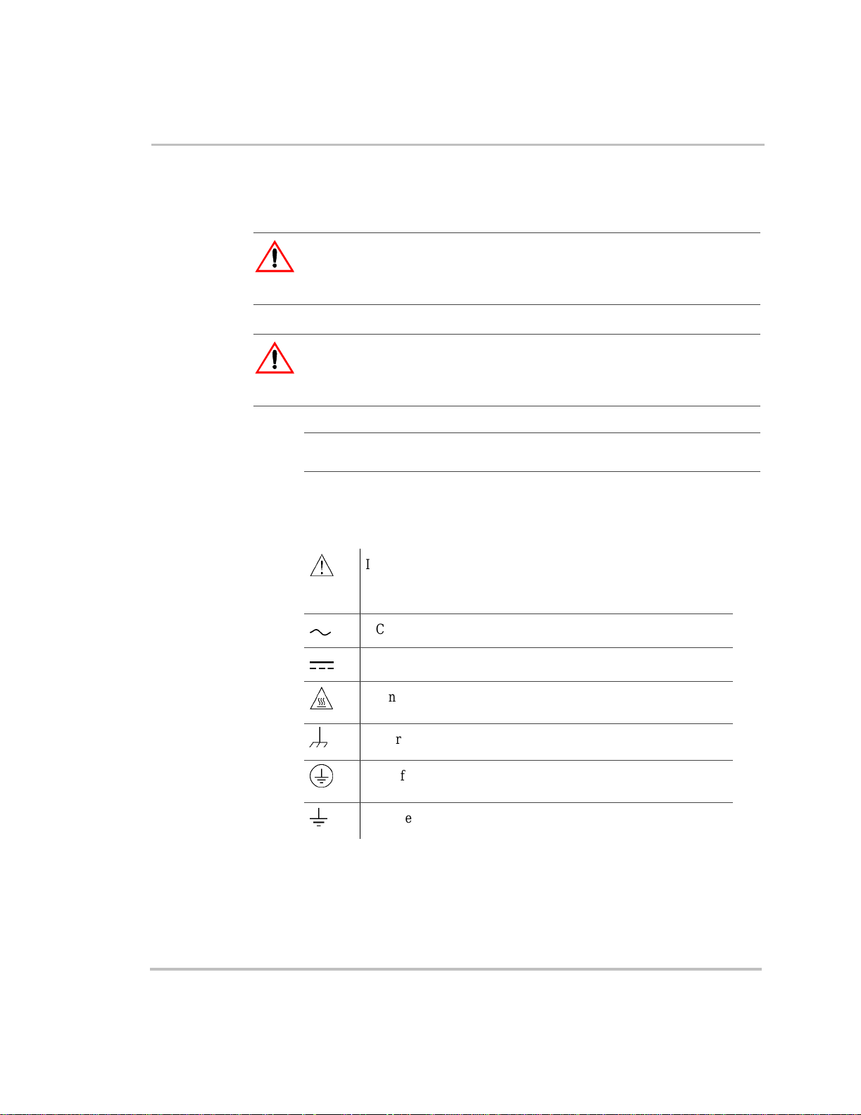
The following symbols are used on the product labels or in this guide.
&
(
%
These notes cont ain i nformat ion tha t i s importa nt for you to k now,
In this guide: Important information, warnings or cautions.
On the product: Important information, warnings or cautions
with further expla nation in the product guides.
AC – Alternating current
DC – Direct current
Warning: Hot surface. Do not touch.
DC ground connection point
AC safety ground connection point from incoming AC source
AC safety ground connection point for AC output (to AC loads)
Abbreviat i ons and Acronyms
For a listing of abbreviations a nd acronyms, refer to the MS2000 Sine
Wave Inverter/Charger Operation Guide.
ii 975-0126-02-01
Page 7

Relat ed Inf o rmation
For related materials on this Xanbus-enabled product and its available
accessori es, se e also:
MS2000 Sine Wave Inverter/Charger Operation Guide (975-0125-02-01)
Automatic Generator Start Owner’s Guide (975-0082-01-01)
System Control Panel Owner’s Guide (975-0083-01-01)
Xanbus System Installation Guide (975-0136-01-01)
More information about Xantr ex Technology Inc. as well as its products
and services, including a complete list of Xanbus-en abl ed devices, is
available at www.xantrex.com
Contact Informatio n
Telephone: 1 800 670 0707 (toll free North America)
Fax: 1 800 994 7828 (toll free North America)
Email: customerservice@xantrex.com
About This Guide
1 360 925 5097 (direct)
1 360 925 5143 (direct)
Web: www.xantrex.com
iii 975-0126-02-01
Page 8

iv 975-0126-02-01
Page 9
Important Safety Instructions
READ AND SAVE THESE INSTRUCTIONS
The MS2000 Sine Wave Inverter/Charger Installation Guide contains
important safety ins tructions.
Before you install and use your MS2000 Sine Wave Inverter/Charger, be
sure to read, understand, and save these safety instructions and those in
the other product guides.
Read all caut ionary mar kings on the i nverter/c har ger, the ba tterie s, and all
appropriate sections of this guide.
WARNING: Risk of injury or loss of life
The MS2000 Sine Wave Inverter/Charger shall not be used in connection with
life support systems or other medical equipment or devices.
WARNING
The following warnings identify conditions or practice s that could result in
personal injury or loss of life.
1. Use of accessories not recommended or sold by Xantrex Tec hnology,
Inc. may result in a risk of fire , elect ri c shock, or injury to perso n s.
2. The inverter/charger is designed to be perm anently connected to your
AC and DC electrical systems. Xantrex recommends that all wiring
be done by a cert ified technician or electrician to ensure adherence to
the local and national ele ctrical codes applicable in your application.
3. To avoid a risk of fire and ele ctric shock, make sure that the existing
wiring is in good c ondition a nd that t he wir e is not und ersi zed. Do not
operate the inverte r/charger with damaged or substandard wiring.
4. To reduce risk of damage and injury, charge only rechargea ble
lead-acid batt eries: flooded, gel, or absorbed glass mat (AGM) types.
Other types of batterie s may burst , causing personal injury and
damage.
5. Do not operate the inverter/charger if it has received a sharp blow,
been dropped, or otherwise damaged in any way. If the unit is
damaged, see the Warranty and Product Information section in the
MS2000 Sine Wave Inverter/Charger Operation Guide.
975-0126-02-01 v
Page 10
Safety
6. Do not disassemble the inverter/char ger; it does not contain userserviceable p arts. Take it to a qu al ified se rvice per son when servi ce or
repair is required. Incorrect reassembly may result in a risk of
electrical shock or fire. Internal capacitors remain charged after all
power is disconnected. For instructions on obtaining service, see the
section in the MS2000 Sine Wave Inverter/Charger Operation Guide.
7. Do not expose the inverter/charger to rai n, snow, or splashing bilge
water.
8. To reduce the risk of electric shock, disconne ct all sources of AC and
DC power from the inverter/char ger before attempting any
maintenance or cleani ng. Turning off controls will not reduce this
risk.
9. The inverter/charger must be provided with equipment grounding
conductors connect ed to the AC input ground and chassis ground
terminals.
CAUTION
Cautions i dentif y co ndit ions o r pra ctic es th at cou ld res ult in dama ge t o the u nit or
other equipment.
T o reduce the risk of overheati ng, keep the ventilation openings clear and
do not install the inverter/charger in a compartment with limited airflow
or inadequate cleara nces around the unit. Refer to “Step 1: Choosing a
Location for the Invert er/Charger” on page 16 for required clear ance.
vi 975-0126-02-01
Page 11

Explosiv e Gas Precaut ions
WARNING: Risk of explosive gases
Working in the vicinity of a lead-acid battery is dangerous. Batteries generate
explosive gases during normal battery operation. For this re ason, it is of utmost
impor t an c e th at each tim e be f o re s er v icing eq u ip m e n t in the vic in i ty of the
battery, you must read this guide and fol low the instructions closely.
1. To reduce the risk of battery explosion, follow these instructions and
those published by the battery manufacturer and the manufacturer of
any equipment you intend to use in the vicini ty of a batt ery. Review
the cautionary markings on these products and on the engine.
2. This equipment contains components which tend to produce arcs or
sparks. To prevent fir e or exp losion , do not inst all the inve rter/cha rge r
in compartments containing batteries or flammable materials or in
locations that requi re ig nition-p rotected e quip ment. This i nclude s any
space containing gasol ine-power machinery, fuel tanks, as well as
joints, fittings, or other connections between components of the fuel
system.
Safety
Personal Precautions When Working With Batteries
1. Someone should be within range of your voice or close enough to
come to your aid when you work near a lead-acid battery.
2. Have plenty of fresh water and soap nearby in case battery acid
contacts your skin, clothing, or eyes.
3. Wear complete eye protection and clothing protection. Avoid
touching your eyes while working near batteries.
4. If battery acid contacts your skin or clothing, wash i mmediate ly with
soap and water. If acid enters your eye, immediately flood the eye
with running cold water for at least ten minutes and get medical
attention immediat ely.
5. Never smoke or allow a spark or flame in the vicini ty of the battery or
engine.
6. Be extra cautious to reduce the risk of dropping a metal tool onto a
battery. It might spark or short-circuit the battery or other electrical
parts that may cause an explosion.
975-0126-02-01 vii
Page 12

Safety
7. Remove personal metal items such as rings, bracelets, necklaces, and
watches when working with a lead-acid battery. A lead-acid battery
can produce a short-circuit current high enough to weld a ring or the
like to metal, causing a severe burn.
8. Never charge a frozen battery.
9. If it is necessary to remove a battery, always remove the grounded
terminal from the b at tery first. M ak e sure all the accessories are off,
so as not to cause an arc.
10. Be sure the area around the battery is well ventilated.
11. Clean the battery terminals. Be careful to keep corrosion from coming
in contact with your eyes.
12. Study all batte ry manufacturer’s specific precautions such as
removing or not removing the cell caps while charging and the
recommended rates of char ge .
13. For refillable (flooded) batteries, add distilled water in each cell until
the battery acid reaches the level specified by the battery
manufacturer. This helps to purge excessive gas from cells. Do not
overfill. Carefully follow the manufacturer’s recharging instructions.
FCC Information to the User
This equipment has been tested and found to comply with the limits for a
Class B digital device, pursuant to part 15 of the FCC Rules. These limits
are designed to provide reasonable protection against harmful
interference when the equipment is operated in a residentia l enviro nment.
This equipment generates, uses and can radiate radio frequency energy
and, if not installed and used in accordance with the instruction guide,
may cause harmful interf erence to radi o communications . However, there
is no guarantee that interference will not occur in a particular installation.
If this equipment does cause harmful interference to radio or television
reception, which can be determined by turning the equipment of f and on,
the user is encouraged to try to correct the interference by one or more of
the following measures:
• Reorient or relocate the rece iving antenna.
• Increase the separation between the equipment and the receiver.
• Connect the equipment into an outl et on a circu it different from that
to which the receiver is connected.
• Consult the dealer or an experie nced r adio/TV technician for help.
viii 975-0126-02-01
Page 13

Contents
Important Safety Instructions
Explosive Gas Precautions - - - - - - - - - - - - - - - - - - - - - - - - - - - - - - - - - - - - - - - - - - - vii
Personal Precautions When Working With Batteries - - - - - - - - - - - - - - - - - - - - - - - - - - vii
FCC Information to the User - - - - - - - - - - - - - - - - - - - - - - - - - - - - - - - - - - - - - - - - - - viii
Installation
Installation Information - - - - - - - - - - - - - - - - - - - - - - - - - - - - - - - - - - - - - - - - - - - - - - 2
Before You Begin the Installation - - - - - - - - - - - - - - - - - - - - - - - - - - - - - - - - - - - - 2
Installation Codes - - - - - - - - - - - - - - - - - - - - - - - - - - - - - - - - - - - - - - - - - - - - - - - 2
About the Xanbus System - - - - - - - - - - - - - - - - - - - - - - - - - - - - - - - - - - - - - - - - - - - - 3
Xanbus Enabled - - - - - - - - - - - - - - - - - - - - - - - - - - - - - - - - - - - - - - - - - - - - - - - - 4
System Accessories - - - - - - - - - - - - - - - - - - - - - - - - - - - - - - - - - - - - - - - - - - - - - - 4
Planning the Installation- - - - - - - - - - - - - - - - - - - - - - - - - - - - - - - - - - - - - - - - - - - - - - 5
Two Key Performance Factors - - - - - - - - - - - - - - - - - - - - - - - - - - - - - - - - - - - - - - - 5
Size and Length of DC Cables - - - - - - - - - - - - - - - - - - - - - - - - - - - - - - - - - - - - 5
Mounting Location of the MS2000 - - - - - - - - - - - - - - - - - - - - - - - - - - - - - - - - - 5
AC, DC, and Network Components - - - - - - - - - - - - - - - - - - - - - - - - - - - - - - - - - - - 6
AC Components - - - - - - - - - - - - - - - - - - - - - - - - - - - - - - - - - - - - - - - - - - - - - - - - 8
AC Input - - - - - - - - - - - - - - - - - - - - - - - - - - - - - - - - - - - - - - - - - - - - - - - - - - 8
Disconnect and Over-Current Prote ction Device - - - - - - - - - - - - - - - - - - - - - - - - 8
Distribution Panels - - - - - - - - - - - - - - - - - - - - - - - - - - - - - - - - - - - - - - - - - - - - 9
AC Wiring - - - - - - - - - - - - - - - - - - - - - - - - - - - - - - - - - - - - - - - - - - - - - - - - - 9
AC Output Neutral Bonding - - - - - - - - - - - - - - - - - - - - - - - - - - - - - - - - - - - - - 9
DC Components - - - - - - - - - - - - - - - - - - - - - - - - - - - - - - - - - - - - - - - - - - - - - - - 11
Batteries - - - - - - - - - - - - - - - - - - - - - - - - - - - - - - - - - - - - - - - - - - - - - - - - - - 11
DC Disconnects and Over-Current Devices - - - - - - - - - - - - - - - - - - - - - - - - - - 11
DC Cabling - - - - - - - - - - - - - - - - - - - - - - - - - - - - - - - - - - - - - - - - - - - - - - - - 11
DC Grounding - - - - - - - - - - - - - - - - - - - - - - - - - - - - - - - - - - - - - - - - - - - - - - 12
Unpacking and Inspecting the Inverter/Charger - - - - - - - - - - - - - - - - - - - - - - - - - - 13
Materials List - - - - - - - - - - - - - - - - - - - - - - - - - - - - - - - - - - - - - - - - - - - - - - - - - 13
Installation Tools and Materials - - - - - - - - - - - - - - - - - - - - - - - - - - - - - - - - - - - - - 14
Installing the Inverter/Charger- - - - - - - - - - - - - - - - - - - - - - - - - - - - - - - - - - - - - - - - - 15
Overview - - - - - - - - - - - - - - - - - - - - - - - - - - - - - - - - - - - - - - - - - - - - - - - - - - - - 15
Step 1: Choosing a Location for the Inverter/Charger - - - - - - - - - - - - - - - - - - - - - - 16
Step 2: Mounting the Inverter/Charger - - - - - - - - - - - - - - - - - - - - - - - - - - - - - - - - 18
Considerations - - - - - - - - - - - - - - - - - - - - - - - - - - - - - - - - - - - - - - - - - - - - - - 18
Step 3: Connecting the AC Input and AC Output Wires - - - - - - - - - - - - - - - - - - - - - 20
975-0126-02-01 ix
Page 14

Contents
General AC Wiring Considerations - - - - - - - - - - - - - - - - - - - - - - - - - - - - - - - - 20
Connecting AC Input Wires - - - - - - - - - - - - - - - - - - - - - - - - - - - - - - - - - - - - - 21
Connecting the AC Output Wires - - - - - - - - - - - - - - - - - - - - - - - - - - - - - - - - - 22
Step 4: Connecting the Main DC Cables - - - - - - - - - - - - - - - - - - - - - - - - - - - - - - - - 23
DC Connection Precaution - - - - - - - - - - - - - - - - - - - - - - - - - - - - - - - - - - - - - - 23
Recommended Cable Sizes and Lengths and Fuse Size - - - - - - - - - - - - - - - - - - - 23
Preparing the Cables - - - - - - - - - - - - - - - - - - - - - - - - - - - - - - - - - - - - - - - - - - 23
Guidelines for Routing the DC Cables - - - - - - - - - - - - - - - - - - - - - - - - - - - - - - 24
Connecting the DC Cables to the Inverter/Charger - - - - - - - - - - - - - - - - - - - - - - 25
DC Grounding - - - - - - - - - - - - - - - - - - - - - - - - - - - - - - - - - - - - - - - - - - - - - - 28
Step 5: Connecting the Echo Charger - - - - - - - - - - - - - - - - - - - - - - - - - - - - - - - - - - 29
DC Connection Precaution - - - - - - - - - - - - - - - - - - - - - - - - - - - - - - - - - - - - - - 29
Preparing the Cable - - - - - - - - - - - - - - - - - - - - - - - - - - - - - - - - - - - - - - - - - - - 29
Connecting the Cable - - - - - - - - - - - - - - - - - - - - - - - - - - - - - - - - - - - - - - - - - - 31
Step 6: Connecting the Batter y Temperature Sensor (BTS) - - - - - - - - - - - - - - - - - - - 31
Mounting Options - - - - - - - - - - - - - - - - - - - - - - - - - - - - - - - - - - - - - - - - - - - - 32
Mounting to the Negative Battery Terminal - - - - - - - - - - - - - - - - - - - - - - - - - - - 32
Mounting to the Side of the Battery Case - - - - - - - - - - - - - - - - - - - - - - - - - - - - 34
Step 7: Connecting to the Network - - - - - - - - - - - - - - - - - - - - - - - - - - - - - - - - - - - 35
Step 8: Perform ing Ch ec k s Prior t o Ini tia l Start-U p - - - - - - - - - - - - - - - - - - - - - - - - 36
Step 9: Testing Your Installation - - - - - - - - - - - - - - - - - - - - - - - - - - - - - - - - - - - - - 37
Testing in Invert Mode - - - - - - - - - - - - - - - - - - - - - - - - - - - - - - - - - - - - - - - - - 37
Testing in Charge Mode - - - - - - - - - - - - - - - - - - - - - - - - - - - - - - - - - - - - - - - - 37
Testing in AC Bypass Mode - - - - - - - - - - - - - - - - - - - - - - - - - - - - - - - - - - - - - 38
Testing the Echo Charger - - - - - - - - - - - - - - - - - - - - - - - - - - - - - - - - - - - - - - - 38
Inverter/Charger Physical Specifications - - - - - - - - - - - - - - - - - - - - - - - - - - - - - - - - - - 38
Battery Information - - - - - - - - - - - - - - - - - - - - - - - - - - - - - - - - - - - - - - - - - - - - - - - - 40
Terminology - - - - - - - - - - - - - - - - - - - - - - - - - - - - - - - - - - - - - - - - - - - - - - - - - - - - - 40
Battery Types - - - - - - - - - - - - - - - - - - - - - - - - - - - - - - - - - - - - - - - - - - - - - - - - - - - - 41
Starting Batteries - - - - - - - - - - - - - - - - - - - - - - - - - - - - - - - - - - - - - - - - - - - - - - - 41
Deep Cycle Batteries - - - - - - - - - - - - - - - - - - - - - - - - - - - - - - - - - - - - - - - - - - - - - 41
Sealed Gel-Cell - - - - - - - - - - - - - - - - - - - - - - - - - - - - - - - - - - - - - - - - - - - - - - - - 42
Environment - - - - - - - - - - - - - - - - - - - - - - - - - - - - - - - - - - - - - - - - - - - - - - - - - - 42
Location - - - - - - - - - - - - - - - - - - - - - - - - - - - - - - - - - - - - - - - - - - - - - - - - - - - - - 42
Enclosures - - - - - - - - - - - - - - - - - - - - - - - - - - - - - - - - - - - - - - - - - - - - - - - - - - - - 43
Temperature - - - - - - - - - - - - - - - - - - - - - - - - - - - - - - - - - - - - - - - - - - - - - - - - - - 43
Battery Bank Sizing - - - - - - - - - - - - - - - - - - - - - - - - - - - - - - - - - - - - - - - - - - - - - - - - 44
Estimating Battery Requirements - - - - - - - - - - - - - - - - - - - - - - - - - - - - - - - - - - - - 45
Battery Bank Sizing Example - - - - - - - - - - - - - - - - - - - - - - - - - - - - - - - - - - - - 46
Battery Bank Sizing Worksheet - - - - - - - - - - - - - - - - - - - - - - - - - - - - - - - - - - - 47
x 975-0126-02-01
Page 15

Contents
Monthly Battery Maintenance - - - - - - - - - - - - - - - - - - - - - - - - - - - - - - - - - - - - - - -48
Preparation for Cleaning Batteries - - - - - - - - - - - - - - - - - - - - - - - - - - - - - - - - - - - -49
Clothing - - - - - - - - - - - - - - - - - - - - - - - - - - - - - - - - - - - - - - - - - - - - - - - - - - -49
Tools - - - - - - - - - - - - - - - - - - - - - - - - - - - - - - - - - - - - - - - - - - - - - - - - - - - - -49
Equipment - - - - - - - - - - - - - - - - - - - - - - - - - - - - - - - - - - - - - - - - - - - - - - - - -49
Supplies - - - - - - - - - - - - - - - - - - - - - - - - - - - - - - - - - - - - - - - - - - - - - - - - - - -49
Maintaining and Cleaning - - - - - - - - - - - - - - - - - - - - - - - - - - - - - - - - - - - - - - - - - -50
Battery Enclosure and Batteries - - - - - - - - - - - - - - - - - - - - - - - - - - - - - - - - - - -50
Terminals & Lugs - - - - - - - - - - - - - - - - - - - - - - - - - - - - - - - - - - - - - - - - - - - -50
Battery Cables - - - - - - - - - - - - - - - - - - - - - - - - - - - - - - - - - - - - - - - - - - - - - - - - -51
Cabling & Hook-up Configuratio ns - - - - - - - - - - - - - - - - - - - - - - - - - - - - - - - - - - -52
Parallel Connection - - - - - - - - - - - - - - - - - - - - - - - - - - - - - - - - - - - - - - - - - - -52
Series Connection - - - - - - - - - - - - - - - - - - - - - - - - - - - - - - - - - - - - - - - - - - - -53
Series-Parallel Connections - - - - - - - - - - - - - - - - - - - - - - - - - - - - - - - - - - - - - -54
Index
- - - - - - - - - - - - - - - - - - - - - - - - - - - - - - - - - - - - - - - - - - - - - - - - - - - - - - - - - - - -55
975-0126-02-01 xi
Page 16

xii
Page 17

Figures
Figure 1 Typical Xanbus System Diagram- - - - - - - - - - - - - - - - - - - - - - - - - - - - - - - 3
Figure 2 Typical Marine Electrical System - - - - - - - - - - - - - - - - - - - - - - - - - - - - - - 7
Figure 3 MS2000 Hardware Materials as Shipped - - - - - - - - - - - - - - - - - - - - - - - - 13
Figure 4 Approved Mounting Orientations - - - - - - - - - - - - - - - - - - - - - - - - - - - - - 19
Figure 5 Front Panel with Wiring Compartment - - - - - - - - - - - - - - - - - - - - - - - - - - 20
Figure 6 AC In and AC Out: Hardwiring Completed- - - - - - - - - - - - - - - - - - - - - - - 22
Figure 7 DC Cable Connections- - - - - - - - - - - - - - - - - - - - - - - - - - - - - - - - - - - - - 26
Figure 8 DC Terminal Covers - - - - - - - - - - - - - - - - - - - - - - - - - - - - - - - - - - - - - - 26
Figure 9 Completed DC Wiring- - - - - - - - - - - - - - - - - - - - - - - - - - - - - - - - - - - - - 27
Figure 10 Completed DC Grounding - - - - - - - - - - - - - - - - - - - - - - - - - - - - - - - - - - 28
Figure 11 Echo Charger Port- - - - - - - - - - - - - - - - - - - - - - - - - - - - - - - - - - - - - - - - 29
Figure 12 Inserting Cable into the Echo Charger Connector- - - - - - - - - - - - - - - - - - - 30
Figure 13 BTS with Cable - - - - - - - - - - - - - - - - - - - - - - - - - - - - - - - - - - - - - - - - - 31
Figure 14 BTS Mounted on the Negative Battery Terminal - - - - - - - - - - - - - - - - - - - 32
Figure 15 Connecting the BTS Cable to Battery Temp. jack- - - - - - - - - - - - - - - - - - - 33
Figure 16 BTS Mounted on the Battery Case- - - - - - - - - - - - - - - - - - - - - - - - - - - - - 34
Figure 17 Connecting to a Network Jack- - - - - - - - - - - - - - - - - - - - - - - - - - - - - - - - 35
Figure 18 Inverter/Charger Dimensions - - - - - - - - - - - - - - - - - - - - - - - - - - - - - - - - 39
Figure 19 Batteries Connected in Parallel - - - - - - - - - - - - - - - - - - - - - - - - - - - - - - - 52
Figure 20 Batteries Connected in Series - - - - - - - - - - - - - - - - - - - - - - - - - - - - - - - - 53
Figure 21 Batteries in Series-Parallel Connections - - - - - - - - - - - - - - - - - - - - - - - - - 54
975-0126-02-01 xiii
Page 18

xiv
Page 19

Installation
The Installation Guide provides detailed information for installing the
MS2000 Sine Wave Inverter/Charger, Echo Charge r, and the battery
temperature sensor.
The MS2000 is a Xanbus®-enabled device that typically powers the
Xanbus system. For information on installing the Xanbus system, see
the Xanbus System Installation Guide, which is available for
download at www.xantrex.com.
This Installation Guide provides:
• safety instructions that must be observed during installation
• a diagram of a typical Xanbus system
• information on additional AC and DC components required
• a list of installation tools and materials
• detailed procedures for a typical installation
• installation testing procedures
• battery information
For information on operating the MS2000, see the MS2000 Sine Wave
Inverter/Charger Operation Guide.
Page 20

Installation
Installation Information
Before You Begin t he Installation
Before beginning your installation:
• Read the entire Installa tion Guide so you can plan the installation from
beginning to end.
• Read the Xanbus System Installation Guide to plan your network
requirements.
• Assemble all the tools and materials you require for the installation.
• Review the Important Safety Instruc tions on page v.
• Be aware of all safety and electrical codes which must be met.
WARNING: Electrical shock and fire hazards
Xantrex® recommends all wiri ng be done by qualified personnel. Disconnect all AC and
DC power sources to preve nt accidental shock. Disable and secure all AC and DC
disconnect devices and automatic generator starting devices.
Installation Code s
It is the in s taller’s responsibility to ensure co mpliance with all appli cable installation
codes and regulations.
Applicable instal lation codes vary depending on the specific location and
application of the ins tal l ation . Som e exam p le s are:
• The U.S. National Electrical Code (NEC)
• The Canadian Ele ct rical Co de (CE C )
• Canadian Standards Association (CSA) and American Boat and Yacht
Council (ABYC) standards for insta llation on boats.
External co nne ct ions to the in ve rter/ charger shall comply with the U nited State s
Coast Guard electrica l regulations (33CFR 183, Sub Part 1).
2 975-0126-02-01
Page 21
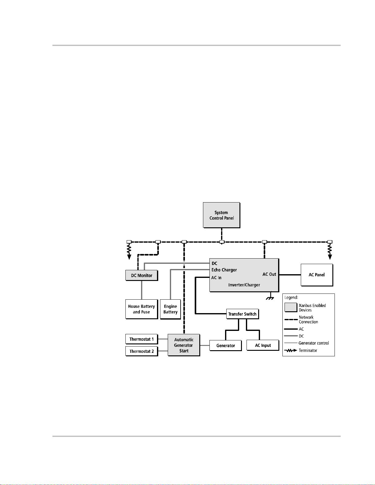
About the Xanbu s Sy stem
The Xanbus system includes the MS2000 Sine Wave Inverter/Charger and other
Xanbus-enabled devices, as shown in Figure 1, “Typical Xanbus System
Diagram”. Each Xanbus-enabled devic e interacts and communicates with the
other devices on the network, creating a power system that can be precisely
configured to your needs.
The MS2000 is the device that typica lly provides power in a Xanbus system. The
System Control Panel provide s configuration and monitoring capability for each
device conn ected to t he Xa nbus sys tem, such as the Autom at ic G en era tor Start
and the MS2000.
In Figure 1, network connec tions ar e represente d by dotted li nes and conve ntional
electrical connections are represented by solid lines. No attempt has been made to
show polarity of electric al connections. Your system requir ements may be more
complex than the basic instal lation shown in Figure 1. Xantrex recommends that
you consult a qualified insta ller or electrician to customize your installation to
meet your requirements.
Installation
Figure 1
975-0126-02-01 3
Typical Xanbus System Diagram
Page 22

Installation
Xanbus Enabled
The Xanbus-enabled designa tion means that this product will work on a Xanbus
network. Xanbus-enabled products are:
• Easy to use. The Xanbus network simplifies operation and automate s routine
• Reliable. Software control eliminates errors due to analog signalling.
• Accurate. Digital information is less susceptible to interference and line loss.
• Upgradeable. Firmware upgrades mean your purchase will remain up to date.
For detailed instructions and a complete list of Xanbus-ena bled devices, visit the
website at www.xantrex.com
System Accessor ies
System accessories currently available that are Xanbus-enabled include the
System Control Panel and Automatic Generator Start. These system accessories
are available from any authorized Xantrex dealer or at www.xantrex.com Please
provide the part number of the acces sor y to the dealer.
Other Xanbus-enabled dev ices will become available in the future.
tasks.
4 975-0126-02-01
Page 23

Planning the Installation
This section provides information to help you plan for a basic installation of the
MS2000.
As your system configuration is de termined, record the details in Information
About Your Syste m on page WA-4 of the MS2000 Sine Wave Inverter/Charger
Operation Guide.
Two Key Performance Factors
T wo key factors in particular will have a major impact on system performance.
Size and Length of DC Cables
To select the appropriate size and length of DC cables, see “DC Cabling” on
page 11.
The DC cables should be as short as possible and large enough to handle the
required current, in accordance with the electrical codes or regulations applicable
to your installation. If battery cables are in excess of 10 feet each (10 feet for the
positive cable and 10 feet for the negative cable) or not of sufficient size, the
voltage drop across the cables will have a negative impact on overall system
performance.
Installation
Mounting Location of the MS2000
T o choose an appropriate location for mounting the inverter/charger, see
“Step 1: Choosing a Location for the Inverte r/Charger” on page 16.
975-0126-02-01 5
Page 24

Installation
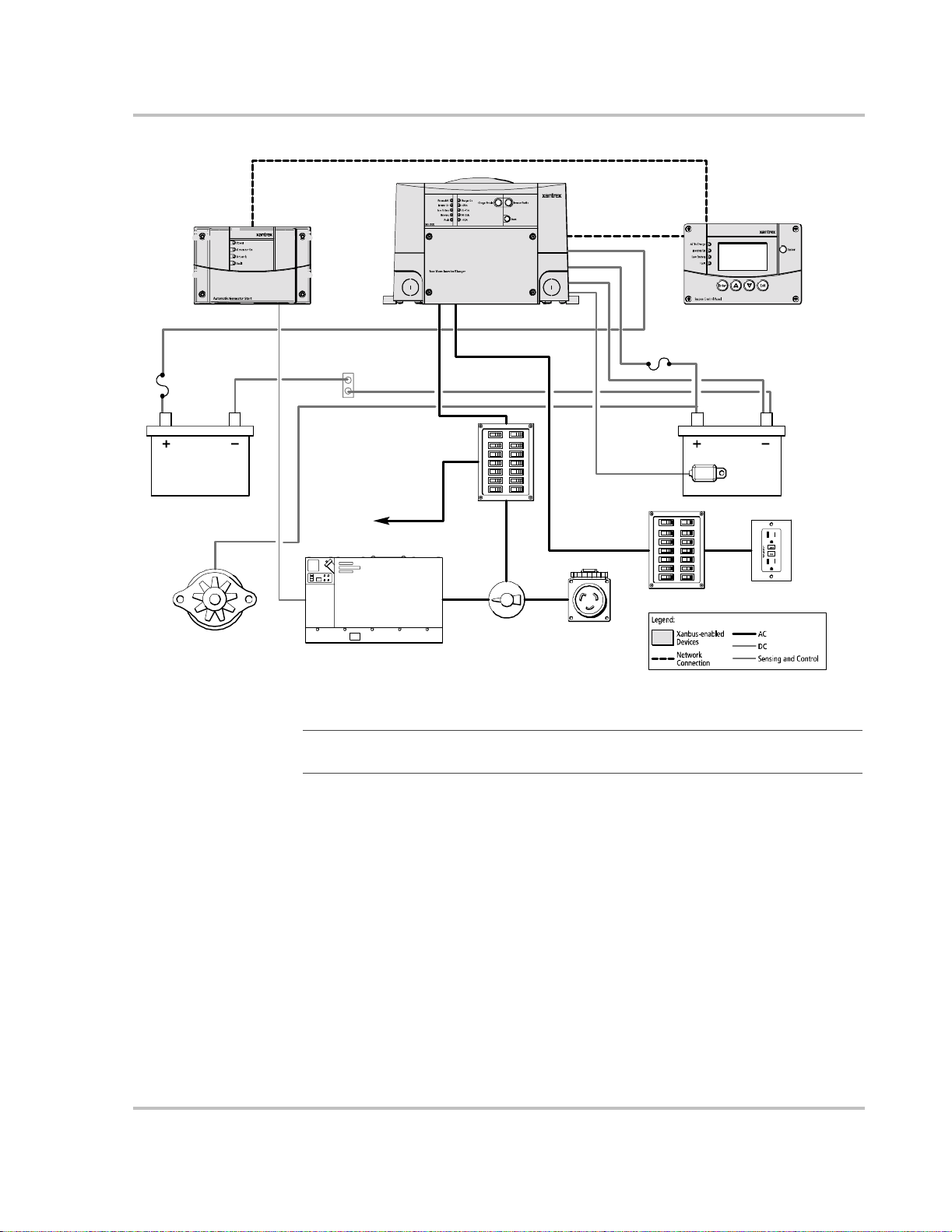
AC, DC, and Network Components
For a successful installation, you need to plan for AC, DC, and network
components of the power system. The AC and DC components are describe d in
this section and illustrated in Figure 2, “Ty pical Marine Electrical System” on
page 7.
AC compone n ts inclu d e:
• Sources of AC input
• AC wiring
• Over-current protection and disconnect devices
• AC distribution panels
DC compone n ts inclu d e:
• Sources of DC power (batteries, for example)
• DC cables
• DC over-current protection and disconnect devices
Network considerati ons include:
• Cables, connectors, network connectors, and terminators for the System
Control Panel and Automatic Gener at or Start, if installing. See Figure 1.
Detailed information on planning and installing your network is available in
the Xanbus System Installation Guide. Refer to the system guide to deter mine
the type of network layout to install, as well as guidelines for installing the
network. This guide is available for download at www.xantrex.com
6 975-0126-02-01
Page 25
Sine Wave Inverter/Charger
Installation
Engine Battery
Alternator
Automatic Generator Start
Non-Inverter Loads
Engine Negative
Terminal/Bus
Generator
AC In
AC Main Panel
AC Out
Transfer Switch
Echo Charger +
DC -
AC Inpu t
(Shore Powe r)
DC +
DC Fuse
Battery Temperature
Sensor
Inverter AC Panel
System Control Panel
House Battery
GFCI
RESET
TEST
Figure 2
Typical Marine Electrical System
Important:
In Figure 2, “Typical Marine Ele ctrical System” on page 7, no attempt has
been made to show all required grounding or overcurrent protection.
975-0126-02-01 7
Page 26

Installation
AC Components
AC Input
A source of 120 volts AC single-phase, 60 Hz alternating current is needed to
provide energy fo r charging batteries and to pass through to AC loads. AC input
can be supplied from an AC source like the utili ty grid (power company), from a
generator, or from the output of a transfer switch. These sources must have their
neutral conductors bonded to ground. See “AC Output Neutral Bonding” on
page 9.
Disconnect and Over-Current Protection Device
T o meet CSA, UL, and electrical code requirements, the AC inputs and outputs of
the inverter/ch arger must be provided with over-current protection such as a
circuit breaker or fuse and a disconnect device on both the AC input and output.
Refer to your applicable installation codes and the following requirements:
AC Input Protection
The circuit bre aker or f use us ed to pr otect the MS2000 must be rated no more than
30 amps and must be approved for use on 120 VAC branch circuits. I f the AC
input power rating is more than 30 amps, you need to add an additional 30 amp
breaker or fuse at the electri c al panel to which the MS2000 AC input is wired.
AC Output
The circuit breaker or fuse must be rated at no more than 30 amps and must be
approved for use on 120 VAC branch circuits.
GFCI Requirements
A GFCI (ground fault circuit int errupter) is a device that deenergizes a circuit
when a current to ground exceeds a specified value that is less than that required
to blow the circuit breaker. GFCIs are intended to protect people from electric
shocks and are usually requi red in wet or damp locations.
Installation in rec reational vehicles requires GFCI protection of certain branch
circuits. Consult all applicable codes .
Tested GFCIs
Compliance with UL standar ds requir es that Xantrex test a nd recommend spe cifi c
GFCIs for use on the output of the inverter. Table 1 lists models that have been
tested and will function pr operly when connected to the AC output of the
MS2000.
8 975-0126-02-01
Page 27

Installation
T ab le 1
Manufacturer Model Number
Hubbell GFR5252WA
Leviton 8599-GY
Pass & Seymour 1594-W
Tested GFCI Models
Disconne ct Dev i ces
Each system requires a method of disconnecting the AC circuits. If the overcurrent protecti on devic e is a circui t breake r, it will also serve as the discon nect. I f
fuses are use d, separate AC disconnect switches will be needed a head of the fuses.
Distribution Panels
Some systems incorporate distribution panels both ahead of the inverter/charger
(the AC source panel) and between the inverter/charger and the loads (the AC
load panel). AC source panel includes a main circuit breaker, which serves as
over-current protection for the panel. Additional circuit breakers serve individual
circuits, one of which serves the inverter/charger.
AC Wiring
Definition AC wiring include s all o f the wires an d conne ctors bet ween the AC source and the
inverter/cha rger input and all of the output wiring between the inverter/cha rger
and the AC load panels, circuit breakers, and loads.
T ype The type of wiring req uired varies according to the electric al codes or regulat ions
applicable to your insta llation. For marine applications, this may be solid wire in
multi-conductor cables, but stranded wire is required if single conductors are
used. All wiring must be rated 90 °C or higher.
Size Wire size has to be coordinated with the overcurrent protection provide d ahead of
the wire involved, in accordance with the electrical codes or regulations
applicable to your insta llation. The wiring used between the AC input circuit
breaker and the inverter/charger input must be sized to match the input breaker
rating. The wiring used between the AC output of the inverter /charger and the AC
output breaker must also be size d to match the input br eaker rating. The wiring
used between the AC output breaker and your loads must be sized to match the
output breaker. Typ ically, No. 10 AWG is required for the 30A breakers required
to be on the MS2000 input and output.
AC Output Neutral Bonding
Bonding system The MS2000 provides a system that autom atically connects the neutral conductor
of the inverter’s AC output circuit to safety ground (“bonding” it) during inver ter
operation, and disconnects it (“unbonding” it) when the inverter/charger is
connected to exte rnal AC or generator power. This system is desig ned to conform
to installation codes that require single-phase AC sources such as inverters and
975-0126-02-01 9
Page 28

Installation
generators to have their neutra l conductor s tied t o ground at the s ource of p ower i n
the same way that the neutral conductor from the utility is tied to ground. These
same codes specify that the neutr al can only be connected to ground in one place
at any one time.
Suitability This automatic neutral- to-ground bonding system is suited for installations in
which the AC input source is known to have a bonded neutral. This will be the
case in most situations: in a utility feed, at an external AC hook-up, or a generator
with a bonded neutral. If not, have an electrician look into bonding the source’s
neutral to ground. See also “AC Input and Output Isola tion” on page 20.
10 975-0126-02-01
Page 29

Installation
DC Components
Batteries
The MS2000 can be installed to operate with two different battery systems—a
house battery and an engine batte ry. Each system may be a single battery or a
bank of several batteries connected in series, parallel, or series-parallel.
House battery The house battery is the lar ge capacity, deep cycle battery that is connected to the
inverter/charger ’s main DC terminals. The MS2000 requires the house battery to
provide the DC current that the inver ter converts to AC power. The house battery
is a 12 volt, lea d-acid deep-cycl e ba ttery or group of ba tteries , all of a flood ed, gel,
or AGM type.
Engine battery The engine bat tery is the battery connect ed to the Echo Charger output. Typica lly,
this will be an engine starti ng battery or an auxiliary battery for loads other than
the inverter.
For general information about batteries, see “Battery Information” on page 40.
For detailed information about specific brands of batteries, you’ll need to consult
individual battery manufacturers.
DC Disconnects and Over-Current Devices
The DC circuit from each battery to the inve rt er/charger must be equipped with a
disconnect and over -current protection device. (Refer to your applic able
installati on code.) This usually consists of a circuit breaker, a “fused-disconnect,”
or a separate fuse and DC disconnect. Do not confuse AC circuit breakers with
DC circuit breakers. They are not interchangeable. The rating of the fuse or
breaker must be matched to the size of cables used in accordance with the
applicable installation codes. The breaker or fuse and disconnect should be
located as close as possible to the battery in the positive cable. Applicable cod es
may limit how far the protection can be from the battery. For recommended fuse
sizes, see Table 2 on page 12.
DC Cabling
DC cabling inc ludes all of the ca bles a nd connec tors betwe en the batt eries, the DC
disconnect and over -current protection device, and the inverter/c harger. All
installations require multi-strand insulated cables as well as disconnect and overcurrent devices. DC cable sizes are indicated by AWG notation. Under the AWG
standard, a larger gau g e num ber indicates a sma ller size d iame te r. Wire size is
usually marked on the cables.
Important:
performance.
A void excessive cable lengths to ensure optimum system
See Ta ble 2 for required DC cable size and required fuse size for the MS2000.
The DC cables must be copper and must be rated 90 °C minimum.
975-0126-02-01 11
Page 30

Installation
DC Grounding
T ab le 2
Maximum DC Cable Length (one way)
Maximum Total Length (two way)
Minimum Recommended Ca bl e Size No. 4/0 AWG
Maximum Batter y Fuse or Breaker
Required DC Input Cable (copper) and Fuse Size
From MS2000 to
house battery bank
10 feet (3 meters) 20 feet (6 meters)
20 feet (6 meters) n/a
300 A class T 15 A DC
From Echo Charger
to engine battery
14 AWG
The inverter/charger DC (chassis) ground terminal needs to be connected to the
boat’s DC grounding bus by a minimum No. 1/0 AWG copper conductor , which is
either rated 90 °C or is bare copper1.
1. Per ABYC E-11, which requires No. 2/0 AWG DC supply conductors for the
MS2000, but allows a DC grounding conductor one size smaller than the DC supply
conductors. The larger No. 4/0 AWG cable size for DC supply conductors shown in
Table 2 is recommended for inverter performance.
12 975-0126-02-01
Page 31

Unpacking and Inspecting the Inverter/Cha r ger
WAR NING: Heavy load
The MS2000 Sine Wave Inverter/Charger weighs approximately 67 lbs (30 kg). The unit
is too heavy for one person to safely lift and mount. Xantrex recommends that two people
lift and m ount the unit. Always use proper lifting techniques during installation to prevent
personal injury.
Materials List
Contents The following materials are in the shipping box:
• MS2000 Sine Wave Inverter/Charger
• DC terminal covers (one red, one black) and four screws
• Bag containing DC terminal hardware:
• Tw o fla t washers
• Tw o lock wash ers
• Two 3/8" bo l ts
• Battery temperatur e sensor
• MS2000 Sine Wave Inverter/Charger Installation Guide
• MS2000 Sine Wave Inverter/Charger Operation Guide
Installation
Figure 3
To unpack and inspec t:
1. Unpack the unit and check the materials list. If anything is missing from the
2. Record the serial number of the MS2000 and other purchase information in
975-0126-02-01 13
MS200 0 Hardware Ma terials as Shipped
shipping box, contact Xantrex Customer Service. See “Contact Information”
on page iii.
the “Warranty and Product Information” section of the MS2000 Sine Wave
Inverter/Charger Operation Guide. You will be asked for this product
information if you need to call Xantrex Customer Service.
Page 32

Installation
3. Save your purchase receipt to use as proof-of-purchase, especially for
warranty servi ce. This is r equire d if the inve rte r/char ge r should nee d warranty
service.
4. Save the original shipping carton and packing materi als. If the inverter/
charger needs to be returned for service, it should be shipped in the original
carton. This is also a good way to protect the inver ter/charger if it ever needs
to be moved.
Installation Tools and Materials
Tools You will need the following tools to install the MS2000 and the battery
temperature sensor.
❐ Wire stripper
❐ Crimping tools for fastening lugs and terminals on DC cables
❐ Phillips screwdriver: #2
❐ Slot screwdriver (1/4" wide blade max.) for AC terminals
❐ Slot screwdriver (1/8" wide blade max.) for Echo Charger connector
❐ Needle-nose pliers
❐ Wrench for DC terminals: 7/16"
❐ Wrench for DC grounding connection: 5/16"
Materials You will need the following materials to complete your installation:
❐ Strain-relief clamp(s) for AC cables: 3/4" and/or 1"
❐ DC battery cables sized according to Table 2 on page 12
❐ Terminals and/or crimp connectors for DC cables (for 3/8" stud size)
❐ Copper wire for DC grounding sized according to Table 2 on page 12
❐ Terminal or crimp connector for DC grounding cable (for 1/4" stud size)
❐ AC and DC disconnect switches and over-current protec tive devices and
connectors as required
❐ Cables for AC input and output wiring
❐ Six ¼"–20 1.25" length steel screws or bolts to mount the MS2000
For a list of tools and material s required to insta ll the networ k, refer to the Xanbus
System Installation Guide, which is available for downl oad at www.xantrex.com.
14 975-0126-02-01
Page 33

Installing the Inverter/Charger
Overview
This section provides detailed information on installing the MS2000. The overall
procedure is divided int o nine steps:
1. Choosing a location
2. Mounting the inverter/charger
3. Connecting the AC input wires and AC output wires
4. Connecting the DC cables
5. Connecting the Echo Charger
6. Connecting the battery temperature sensor
7. Connecting to the network
8. Performing checks prior to initial start- up
9. Testing your installation
Installation
975-0126-02-01 15
Page 34
Installation
Step 1: Choosing a Location for the Inverter/Charger
WARNING: Risk of fire or explosion
This equipme nt is not igniti on p rote cted, and c ontain s com ponents that could produc e arc s
or sparks. To reduce the risk of fire or explosion, do not install this equipment in
compartments containing flammable materials, or in locations that require igniti onprotected eq uipment. This includes any space containing gasoline-powered machinery,
fuel tanks, or joints, fittings, or other connections between components of the fuel sys tem.
WARN ING: Fire hazard
Do not cover or obstruct the ventilation openings. Do not install this equipment in a
compartment with limited airflow. Overheating may result.
The location of the inverte r/charger is a key factor in system performance.
Allow sufficie nt clearance around the unit and install in a well-ventilated
compartment to prevent overheating and premature shutdown of the inverter/
charger.
The inverter should only be installed in a location that meets the following
requirements:
Ventilated Do not operate the inverter/charger in a closed-in area or
restrict ventila tion in any way . The invert er/char ger requires
air circulation to maintain optimum operating temperature
and provide best performanc e. If the unit has inadequate
ventilation, it may shut down due to overheating.
The air vented thr ough t he open ings s hould a lso ha ve a pa th
to circu l ate away from the inverter/ch arger.
Dry Do not allow water or other fluids to drip or splash on the
inverter. Do not expose to rain, snow or water.
Cool Normal air temperature shou ld be between 32 °F and
122 °F (0 °C and 50 °C)—the coo ler the better within this
range.
Clearance Allow as much space around the inverter/charger as
possible. Xantrex recom me nds that other objects and
surfaces be at least 3 inches (76 mm) away from the
ventilation openings for best performance.
Safe Locate the inverter/charger away from battery in a separate
well-ventilated compartment . Do not install the inverter /
charg er in any compartment containing flammable gases or
liquids like gasoline.
16 975-0126-02-01
Page 35

Installation
Close to
battery
compartment
The length and size of your DC cables will affect
performance. Use the DC cables recommended in Table 2
on page 12. The unit should not be installed in the battery
compartment due to th e pos sible presence of explosive
hydrogen gas from the batteries.
Protected
from battery
acid and gase s
Never pl ac e th e inver te r /c h arg er d irectly ab o ve th e
batteries—gases from battery will corrode and damage the
inverter/charger. Never allow battery acid to drip on the
inverter/charger or its wiring when filling the bat teries or
reading their specific gravity.
Orientation To meet regulatory require ments, the MS2000 must be
mounted in an approved mounti ng ori entat ion. S ee Fi gure 4
on page 19. These orientation restrictions are designed to
stop dripping wate r, due to condensation in damp marine
environments, from get ting inside the MS2000.
975-0126-02-01 17
Page 36

Installation
Step 2: Mounting the Inverter/Charger
Considerations
Before mounting the MS2000, take the following two factors into account.
1. The weight of the inverter/charger requires two people to install it.
2. Mounting considerations are shown in Figure 4 on page 19 and described in
Table 3 on page 19.
WAR NING: Heavy load
The MS2000 Sine Wave Inverter/Charger weighs approximately 67 lbs (30 kg). The unit
is too heavy for one person to safely lift and mount. Xantrex recommends that two people
lift and m ount the unit. Always use proper lifting techniques during installation to prevent
personal injury.
The MS2000 dimensions and location of the mounting holes are provided in
Figure 18 on page 39.
Mount your inverter/cha rger before you connect any wires or cables.
To mount the inverter/charger:
1. Remove the inverter/charger from its shipping container.
The inverter/charger is shipped on a packaging board which can also serve as
a template.
2. Remove the four screws that attach the inverter/charger to the packaging
board. Use the box handles provided to move the unit.
Important:
the uni t. See “Installation Tools and Materials” on page 14 for recommended screw size.
3. Verify that all components are present, and record relevant product
informatio n on fo rm WA-4 i n the MS2000 Sine Wave Inverter/Charger
Operation Guide.
4. Select an appropriate mounting location and orientation. To meet regulatory
requirements, the MS2000 must be mounted in one of the two orientations
shown in Figure 4.
5. Use the packaging board as a template to mark the position of the mounting
screws or refer to Figure 18 on page 39.
6. Pilot drill the six mounting holes.
7. Fasten the inverter/charge r to the mounting surface with the six ¼"–20 steel
screws or bolts.
Do not use the four screws that at ta ch the un it to the te mp late for mounti ng
18 975-0126-02-01
Page 37
Installation
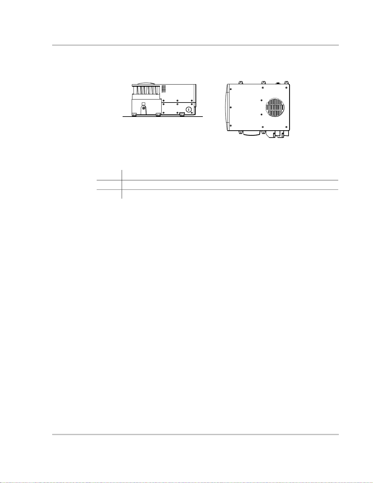
1 - Desktop mount
Figure 4
T ab le 3
Number Approved Mounting Orientation
Description of Approved Mounting Orientations
1Desktop
2 Wall mount orientation, on a vertical surface with DC terminals facing down.
Approved Mounting Orientations
2 - Wall mount
975-0126-02-01 19
Page 38
Installation
Step 3: Connecting the AC Input and AC Output Wires
WARN ING: Fire, shock, and energy hazards
Make sure wiring is disc onnected from all electrical sources before handling. All wiring
must be done in accordance with local and national electrical wiring codes.
General AC Wiring Considerations
AC and DC Wiring Separation Do not mix AC and DC wiring in the same conduit or panel. Consult the applicable installation code for details about DC wiring and AC wiring in vicinity to each other.
AC Input and Output Isolation The AC input and output circuits of this inverter/cha rger are isolated from each other when in invert mode to ensure safe operation. This isolation must be maintained in the installation, by being sur e not to connect AC input and output wiring to a common point. For example, do not route the AC input and output neutrals to a common neutral bus.
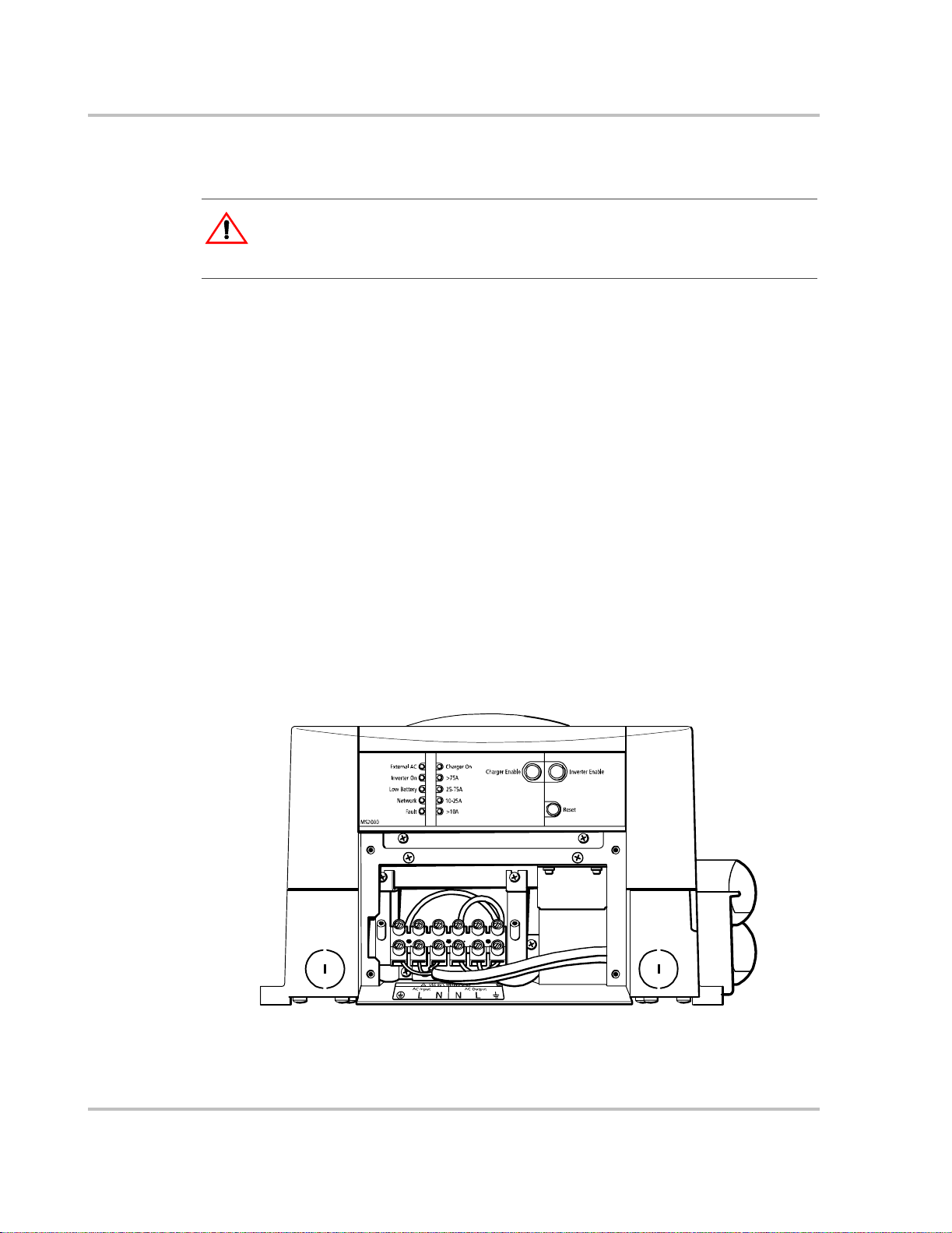
AC Wiring Compartment For your reference, the AC wiring compartment is shown in Figure 5.
AC Knockouts There are two 3/4" trade-size knockouts on the front panel for AC wiring, as show n in Fig ure 5 . For eas i er wi ri ng acc es s, the re are al so knockouts on either side of the unit ( not shown). The side knockouts are 1" trade size knockouts. Use the same trade size of strain relief as the trade size of the knockout (s) you are using.
AC Wiring Terminals The AC wiring terminals accept cables of a specific size. See “AC Wiring” on page 9 for required sizes.
Figure 5
20 975-0126-02-01
Front Panel with Wiring Compartment
Page 39

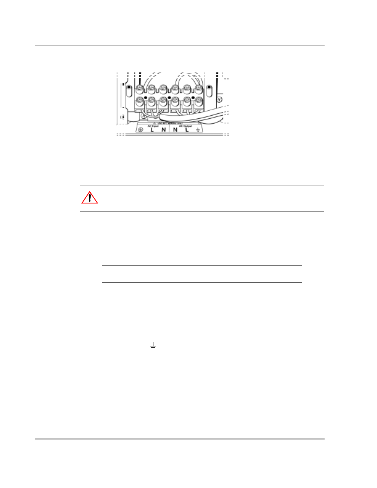
Connecting AC Input Wires
A detailed view of the MS2000 wiring compartment with the AC compartment
panel removed is shown in Figure 6. The terminal block is used to hardwire the
AC input and AC output connections.
CAUTION: Equipment damage
The terminal blo ck is sp lit into INPUT and OUTPUT sections. Damage may occur if the
unit is wired incorrectly.
Do not remove or loosen factor y ins talled wiring.
When making the AC input an d AC output connections, observe the correct color
code for the appropriate AC wire, as described in Table 4.
Installation
T ab le 4
Color AC Wire
Black Line
White Neutral
Green or bare copper Ground
Color Codes for Typical AC Wiring
To make the AC input connections:
1. Locate the wiring compartment cover panel and remove the four screws.
2. Remove the cover panel from the unit to access the wiring compartment.
3. Remove one of the AC knockouts from the front or side of the unit. Do not
leave the knockout inside the wiring co mpartment.
4. Install a strain-relief clamp in the AC knockout.
5. Run the AC wiring through the strain-relief clamp.
6. Strip approximately 2 inches (50 mm) off the jacket from the AC cable and
sepa r ate th e th r ee wires.
7. Using the 1/4" blade slot screwdriver, loosen the wire attachment screws on
the terminals. Do not remove the screws.
8. Insert the line wire into "L", the neutral wire into "N", and the ground wire
into ground (
), as shown in Figure 6 on page 22. Observe the color codes
described in Table 4.
9. Tighten the wire attachment screws. Leave some slack wire inside the wiring
box.
10. Secure the strain-relief clamp on the AC input cable ja cket.
975-0126-02-01 21
Page 40
Installation
Figure 6
Connecting the AC Output Wires
CAUT ION: Risk of equipment damage
Do not connect the output of the inverter to any incoming AC source.
To make the AC output wi ring co nn ect ions:
1. Remove one of the AC knockouts from the front or side of the unit. Do not
leave the knockout inside the wiring co mpartment
2. Install a strain-relief clamp in the AC knockout.
Important:
input and AC output wiring through the same AC knockout.
3. Run the AC wiring through the strain-relief clamp.
4. Strip approximately 2 inches (50 mm) off the jacket from the AC cable and
sepa r ate th e th r ee wires.
5. Using the 1/4" blade slot screwdriver, loosen the wire attachment screws on
the AC output terminals. Do not remove the screws.
AC In and AC Out: Hardwiring Completed
The applicable installation code may not allow you to run the AC
6. Insert the line wire into "L", the neutral wire into "N", and the ground wire
into ground (
T able 4.
7. Tig hten the wire attachment scre ws. Leave so me slack wire inside the wiring
box.
8. Secure the strain -re lief clamp on the AC outp ut cabl e ja cket .
9. Attach the wiring compartment cover panel and tighten the four screws.
10. Connect the outgoing AC wires to an AC load panel equipped wit h circ uit
breakers.
22 975-0126-02-01
), as shown in Figure 6. Observe the color codes described in
Page 41

Step 4: Connecting the Main DC Cables
DC Connection Precaution
WARNING: Energy hazard
Connect and disc onnect DC wiring onl y after ope ning the discon nect switc hes or bre akers
at all AC and DC sources.
Recommended Cable Sizes and Lengths and Fuse Size
For the best load starting sur ge performance, the DC cables should be as short as
possible and lar ge enough to handle the required current, in accordance with the
electrical code s or regul ations applicable to your installation. Avoid excessive
cable lengths. The DC cables must be copper and must be rated 90 °C
minimum.
For recommended DC cables and fuse size, see Table 2, “Required DC Input
Cable (copper) and Fuse Size” on page 12. Using a longer or smaller gauge cable
may cause the inverter to shut down under heavy load.
Installation
Preparing the Cables
To prepare the DC cables:
1. Cut the negative and positive cable to the required lengt h. S trip off enough
insulation so you can instal l the terminals you will be using.
Xantrex recomm ends the use of crimp connectors. The connector should be
designed for a 3/8" s tud s ize to c onnect to the MS2000 . If a cr imp connecto r i s
used, it should be crimped using the tool indicated by the connector
manufacturer.
2. Cut the DC ground cable to the required length. Strip of f enough insula ti on so
you can install the terminals you will be using.
Xantrex recomm ends the use of crimp connectors. The connector should be
designed for a 1/4" s tud s ize to c onnect to the MS2000 . If a cr imp connecto r i s
used, it should be crimped using the tool indicated by the connector
manufacturer.
3. Attach the connectors to the ends of all cables. Make sure no stray wire
strands protrude from the connectors.
975-0126-02-01 23
Page 42

Installation
Guidelines for Routing the DC Cables
Follow these guidelines to en sure maximum performance.
WARNING: Fire and shock hazard
Route the cabl es away from sharp edges that might damage the insulation. Avoid sharp
bends in the cable.
• Do not attempt to use the chassis in place of the main bank battery negative
connection for groun ding. The inverter requires a reliable return path directly
to the battery.
• T o reduce the chance of radio frequency interference, keep the positive and
negative cables close together—ideally, held togethe r by straps, loom, or
insulated clamps at regular intervals.
• To ensure maximum performance from the inverter, do not route your DC
cables through a DC distribution panel, battery isola tor, or other device that
will cause additional voltage drops. The exception is the DC fuse and
Disconnect or the DC circuit brea ker which is required at the batte ry to
protect the DC w iri ng.
• T o help avoid damage caused by reverse polarity battery connection, it is a
good idea to mar k each end of each cab le t o id entify it as a pos itiv e (red ) or
negative (black) cable before routing the wiring.
24 975-0126-02-01
Page 43

Connecting the DC Cables to the Inverter/Charger
WARN ING: Fire hazard
Use only appropriately sized copper cable. Loose connections or improper connections
will overheat . Make sure the bolts supplied by Xantrex on the inve rter/charger are
tightened to a torque of 15–16 ft-lbs (20.4–21.7 Nm). Torque all other connections to the
manufacturer’s specifications. Make sure the DC cable, washers, and bolt are assembled
in the order shown in Figure 7.
CAUTION: Reverse polarity damage
Before making the fin al DC connection or closi ng the DC breaker or disconnect, check
cable polarity at both the battery and the inv er ter/char g er. Positive (+) must be connected
to positive (+). Negative (–) must be connected to negative (–).
To connect the DC cables:
1. Route the DC cables from the house battery bank to the inverter/charger.
Observe the “Guidelines for Routing the DC Cables” on page 24.
2. Install a DC fuse and disconnect switch or a DC circuit breaker between the
inverter/cha rger and the battery. They must be installed in the positive side of
the DC circuit, as close as possible to the battery.
Installation
This protects your batte ry and wiring in case of accidental shor ting. See
T able 2 on page 12 for required fuse or breaker size. Open the DC disco nnect
switch or turn off the DC circuit breaker.
3. Connect one connector on the POSITIVE (+) cable to the POSITIVE DC
terminal on th e inverter/charger, as shown in Figure 7. The connector goes on
first, then the flat w ash er (s teel ), lo ck washer (steel), and 3/8 " bo lt (bras s ).
4. Connect the other connector to the POSITIVE (+) terminal on the fuse or
breaker. Observe polarity carefully while completing the installation.
Use a wrench to tighten the bolt to a torque of 15–16 ft-lbs (20.4–21.7 Nm) at
the inverter/ch arger end. Observe the fuseholder or breaker manufacture r’s
recommendation at the other end.
5. Connect one connector on the NEGATIVE (–) cable to the NEGATIVE (–)
DC terminal on the inverter/charger, as shown in Figure 7. The connector
goes on first, then the flat washer (steel), lock washer (steel), and 3/8" bolt
(brass).
975-0126-02-01 25
Page 44

Installation
Figure 7
DC Cable Connections
6. Before proceeding, che ck that the cable polarity is correct: POSITIVE (+) on
the inverter/ch arger is connected to the POSITIVE (+) on the battery, and
NEGATIVE (–) cable is connected to the NEGATIVE (–) terminal on the
inverter/charger.
Important:
normal when this connection is made.
The next step is the last cable connection you need to make. A spark is
7. Connect the other end of the NEGATIVE (–) cable to the NEGATIVE (–)
terminal on the battery.
8. Use a wrench to tighten the bolt to a torque of 15–16 ft-lbs (20.4–21.7 Nm
) at
the inverter/charger end.
9. Attach the DC terminal covers using the screws provided to protect the DC
terminals, as shown in Figure 8.
Figure 8
26 975-0126-02-01
DC Terminal Covers
Page 45

Installation
!
Figure 9
Completed DC Wiring
975-0126-02-01 27
Page 46

Installation
DC Grounding
The Chassis Ground point on the inverte r/char ge r is used to connect the chassis of
the inverter/ch arger to your system’s DC grounding point , as req uired by
regulations for some insta llations. Use copper wire that is either bare or provided
with green insulation.
The grounding guideline given below assumes you are using the code-complia nt
DC supply cable and fuse sizes indicated in this Installation Guide. If you are
using differ ent sizes, refer to the applicable code for DC grounding detail.
To connect the chassis ground:
1. Using the appropriate wrench, loosen the bolt on the chassis ground point
shown in Figure 10.
2. Connect the DC grounding cable (No. 1/0 AWG or larger copper cable)
between the chassis ground point a nd the DC grounding point for your
system, usually the boat’s DC grounding bus.
3. Tighten the bolt to a torque of 3.5–3.8 ft-lbs (4.5–5.2 Nm).
chassis ground point
Figure 10
28 975-0126-02-01
Completed DC Grounding
Page 47

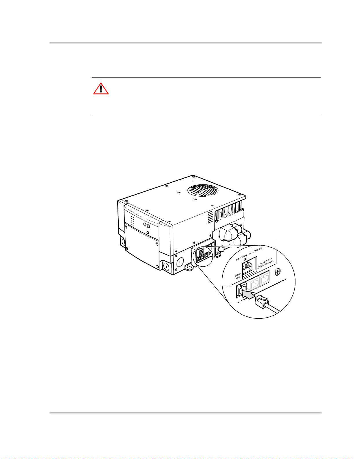
Step 5: Connecting the Echo Charger
The Echo Charge r connection is made above the net work and battery temperature
sensor jacks. See Figure 11.
Echo Charger port
Installation
!
Figure 11
The Echo Charger requir es a single positive cable connected between the Echo
Charger port on the MS2000 and the engine batter y. That battery and the house
battery bank must have their negative terminals connected to the boat’s DC
negative bus for the Echo Char ge to function (see Figure 2 on page 7).
DC Connection Precaution
WARNING: Energy hazard
Connect and disc onnect DC wiring onl y after ope ning the discon nect switc hes or bre akers
at all AC and DC sources.
Preparing the Cable
For the best charging pe rfor mance, the DC cable should be as short as possible
and large enough to handl e the required current, in accordance with the electrical
codes or regulations applicable to your installation.
Although the Echo Charger output is limited to 10 A, it is recommended to use
No. 14 AWG 90 °C cable to minimize volta ge drops.
Battery Temp. jack
Echo Charger Port
Network jacks
To prepare the Echo Charger cable:
1. Cut the cable to the required length. Strip off 1/4" insulation on the Echo
Charger connection side.
2. Remove the Echo Charger connector from the Echo Charger port on the side
of the MS2000.
975-0126-02-01 29
Page 48

Installation
3. Using the slot screwdriver with a 1/8" blade, press down on the tension cl ip
through the slot located at the top of the connector. While pressing down on
the tension clip, insert the end of the cable with insulat ion removed into the
left-side round hole at the front of the connector. See Figure 12.
OR
You can also insert the screwdriver blade into the square hole above the left-
side hole and twist the screwdri ver to press down on the tension clip before
inserting the cable .
Important:
anything internally and should not be used. If you connect the Echo Charger to the engine
battery using the right-side connector, the Echo Charger will not work.
The right-side hole on the Echo Charger connector does not connect to
4. To secure the cable, remove the screwdriver to release the tension clip.
To MS2000
Echo Charger port.
Insert screwdriver into left-side
top notch or front notch.
Figure 12
Inserting Cable into the Echo Charger Connector
5. Install the disconnect and 15 A DC over-current pr otection between the other
end of the cable and the battery positive (+) terminal, as close as possi ble to
the battery in accordance with codes.
6. Open the disconnect switch or remove the fuse.
30 975-0126-02-01
Page 49

Connecting the Cable
Installation
WARNING: Energy hazard
Connect and disc onnect DC wiring onl y after ope ning the discon nect switc hes or bre akers
at all AC and DC sources.
To connect the Echo Charger cable:
1. Route the cable from the engine battery to the Echo Charger port on the
MS2000.
2. Connect the cable to the fuse on the PO SITIVE (+) terminal of the engine
battery.
3. Plug the Echo Charger connector into the port on the MS2000.
4. If it is not already connected, connect the engine battery negative terminal to
the engine negative ter minal/bus.
This cable must be siz ed for all t he loads on the eng ine batte ry (inclu ding st art
current), not just the Echo Charger.
Step 6: Connecting the Battery Temperature Sensor (BTS)
Installing a bat tery temperature sensor (BTS) extends the life of the house battery
bank by preventi ng overch ar ging in wa rm tempera tures and under char ging i n cold
temperatures. With a BTS monitoring the battery temperature, the volt age
delivered to the house batte ry bank is adjusted according to the battery’s actual
temperature.
A 25-foot (7.6 m) cable is supplied with the BTS, as shown in Figure 13.
Figure 13
975-0126-02-01 31
BTS with Cable
Page 50

Installation
WARNING: Energy and explosion hazard
Review the “Important Safety Instructions” on page v.
Mounting Options
You can mount the BTS in one of two ways:
• Mounting the sensor to the negative post of one of the house batteries allows
the internal battery temperature to be sensed and provides the most accurate
results.
• Attaching the sensor to the side of one of the house batteries using the selfadhesive backing also provide s good results in most situations.
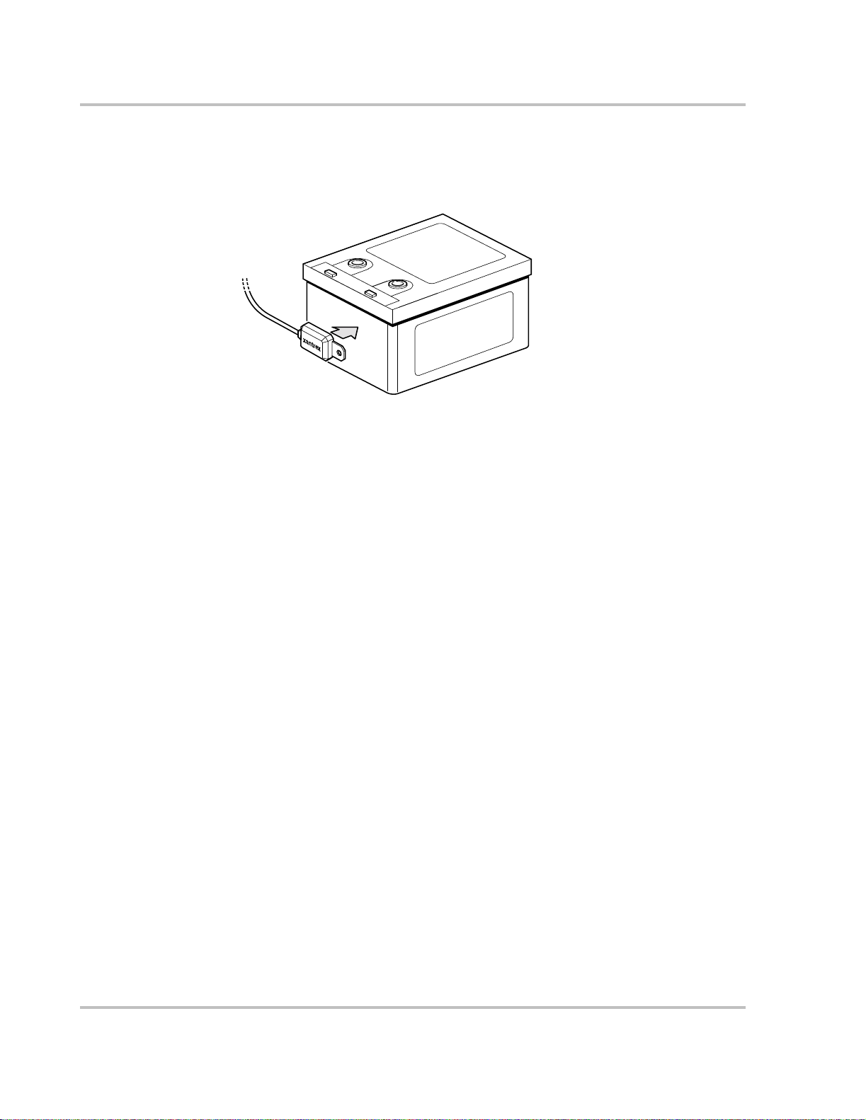
Mounting to the Negative Battery Terminal
To mount the sensor on the negative battery terminal :
See Figur e 14.
Figure 14
1. Select the battery to be monitored. The battery temperature sensor must be
connected to the house battery bank, which is directly connected to the
inverter/charger.
2. Switch off all devi ces operatin g from t he bat tery, or open the ba tter y switc h (if
present) to disconnect the battery.
3. Wait 10 minutes for any explosive battery gases to dissipate.
4. Remove the nut that connects the existing wir ing ring terminals to the battery
negative terminal stud.
5. Move or reorient the existing wiring ring terminals on the battery negative
terminal stud, so there is a flat surface on which to seat the battery
temperature sensor mount ing plate.
You may need to bend the r ing te rmin al cri mp and/ or wires sli ghtly downwa rd
to allow the sensor to seat flush to the top surfa ce of the upper ring terminal.
32 975-0126-02-01
BTS Mounted on the Negative Battery Terminal
Page 51
Installation
6. Mount the sensor directly on top of the ring terminal, as shown in Figure 14,
and firmly tighten the termina l nut.
WARN ING: Fire hazard
In this procedure, you must install the DC wire on the battery terminal first. Then the
sensor is insta lled on top of the DC wire. This sequence is required to provi de the best
connection to the battery and to ensure correct performance of the sensor.
7. Check to ensure that the sensor and all wires are held firmly and cannot be
moved.
8. Turn the battery switch on again ( if you opened it in Step 2).
9. Route the sensor cable to the inverter/char ger and plug it into the Battery
Temp jack, as shown in Figure 15 . Secure the cable along i ts lengt h .
Figure 15
975-0126-02-01 33
Connecting the BTS Cable to Battery Temp. jack
Page 52
Installation
Mounting to the Side of the Battery Case
To mount the sensor on the ba tt ery cas e:
See Figur e 16.
Figure 16
BTS Mounted on the Battery Case
1. Select the battery from the house battery bank to be monitored.
2. Select a side suitable for attaching the sensor.
The surface where the sensor is to be mounted must be flat and free from
reinforcing ribs or other raised features. This surface must be in direct internal
contact with the battery el ectr olyte. Do not install the sensor near the top of
the battery or on the battery’s top surface.
3. Clean the selected area thoroughly to remove any oil or grease tha t could
prevent the sensor fro m adhering to the batte ry case. Allow the battery case to
dry thoroughly.
4. Peel the protective backing from the self-adhesive strip on the rear of the
sensor.
5. Press the sensor firmly against the clean side of the battery to fix it in place, as
shown in Figure 16.
6. Route the sensor cable to the inverter/char ger and plug it into the Battery
T emp. jack, as shown in Figure 15. Secure the cable along its length.
34 975-0126-02-01
Page 53

Step 7: Connecting to the Network
For your reference, Figure 17 shows where the network connections are made on
the MS2000. The network cable can be pl ugged into ei ther one of the two ne twork
jacks on the MS2000.
CAUTION: Equipment Damage
Connect the MS2000 only to other Xanbus compatible device s.
Although t he cabling and connectors used in this network system are the same as Ethernet
connectors, this network is not an Ethernet system. Equipment damage m ay result from
attempting to connect two different systems.
Detailed information on planning and installing your network is available in the
Xanbus System Installation Guide . Refer to the this guide to determi ne the type of
network layout to instal l, a s well as guidelines for insta lling the network.
The Xanbus System Installation Guide is available for download at
www.xantrex.com
Installation
Figure 17
975-0126-02-01 35
Connecting to a Network Jack
Page 54

Installation
Step 8: Performing Checks Prior to Initial Start-Up
Before testing your insta llation, ensure these conditions are met:
❐ Chassis and AC grounds are properly installed.
❐ AC input connections and AC output connections are wired correctly on the
terminal block and not reversed.
❐ Positive (+) battery cable is connected to the house bank posit ive (+) battery
terminal through the DC fuse and disconnect switch or DC circuit breaker.
❐ Negative (–) battery cable is connected to the house bank negative (–) battery
terminal.
❐ House battery voltage is within the proper range for this unit
(10.3–15.3 volts DC).
❐ DC disconnect switch or breaker is turned off.
❐ Echo Charger disconnect switch is off or fuse is removed.
❐ Echo Charger connections are correct: posi tive (+) cable runs from the Echo
Charger to the positive terminal of the engine battery.
❐ Both the house battery and the engine battery negative terminals are
connected to the engine negative terminal/bus.
❐ AC input and output br eakers are turned off.
❐ All connections are tight.
36 975-0126-02-01
Page 55

Step 9: Testing Your Installation
WARNING: Shock hazard
The Inverter Enable button on the MS2000 and the optional accessories do not disconnect
DC or AC input power to the MS2000.
There are several tests to be performed for testing your installation. These tests
will verify that:
• The MS2000 works in invert mode.
• The MS2000 works in charge mode.
• The MS2000 works in AC bypass mode.
• The Echo Charger is functioning.
Testing in Invert Mode
To test the inverter/charger in invert mode, using a 100 watt light bulb as the
test load:
1. Close the DC disconnect switch or the DC circuit brea ker to suppl y DC p ower
to the MS2000.
Installation
2. Verify that all lights on the front panel illuminate during the initialization
3. Connect the MS2000 to the test light by closing the AC breaker that contols
Testing in Charge Mode
To test the MS2000 in charge mode:
1. Close the AC supply breaker to supply AC power to the unit.
2. After a few seconds, veri fy that the Ext ernal AC an d Char ger ON l ights on the
Important:
occurs over an extended period of time.
The unit takes 10 to 30 seconds to initial ize.
stage. If other Xanbus-enabled devices are connected, the Network light will
be illuminated. The Invert light illuminates only if the Invert Enable button
light is also illuminate d. If the unit is powered up for the first time, the
Inverter On light will be off. To turn the inverter on, press the Invert Enable
button.
the circuit that the test light is connected to.
If the light bulb illuminate s, the installation has been successful.
front panel illumina te. One of the current range lights (>75A, 25–75A,
10–25A, >10A) should also illuminate.
The charging process, whether it is three-stage or two-stage charging,
975-0126-02-01 37
Page 56

Installation
Testing in AC Bypass Mode
To test the MS2000 in transfer mode:
1. Close the AC supply breaker to supply AC power to the unit.
The transfer from invert to AC input power occurs.
2. Press the Charger Enable button to disable the charger. Verify that the Charger
Enable light is not illumina ted. AC loads will still be powered.
Testing the Echo Charger
1. Close the Echo Charger disconnect switch or replace the fuse.
2. Check the System screen on the System Control Panel and ensure the
MS2000 is in the Bulk or Absorption charge cycle.
3. From the MS2000 advanced menu on the System Control Panel, verify that
the Echo Charger is enabled.
4. If the Echo Charger is enabled, verify that the MS2000 advanced menu is
displaying the Echo Char ger current and voltage.
The current displayed will de pend on the voltage level of the house bank and the
voltage diff erence between the house battery bank and the engine battery.
Inverter/Charger Physical Specifications
For complete inverter/charger specifications, refer to the MS2000 Sine Wave
Inverter/Charger Operation Guide.
The physical specif ications of t he MS2000 are shown in F igure 18 on page 39 and
described in Table 5.
T ab le 5
Length 16.19 inches (411 mm)
Width 14.20 inches (361 mm)
Height 8.1 inches (208 mm)
Weight 67 lbs (30 kg)
DC terminal bolt siz e 3/8 inch
Ground terminal bolt size 1/4 inch
MS2000 Physical Specifications
38 975-0126-02-01
Page 57
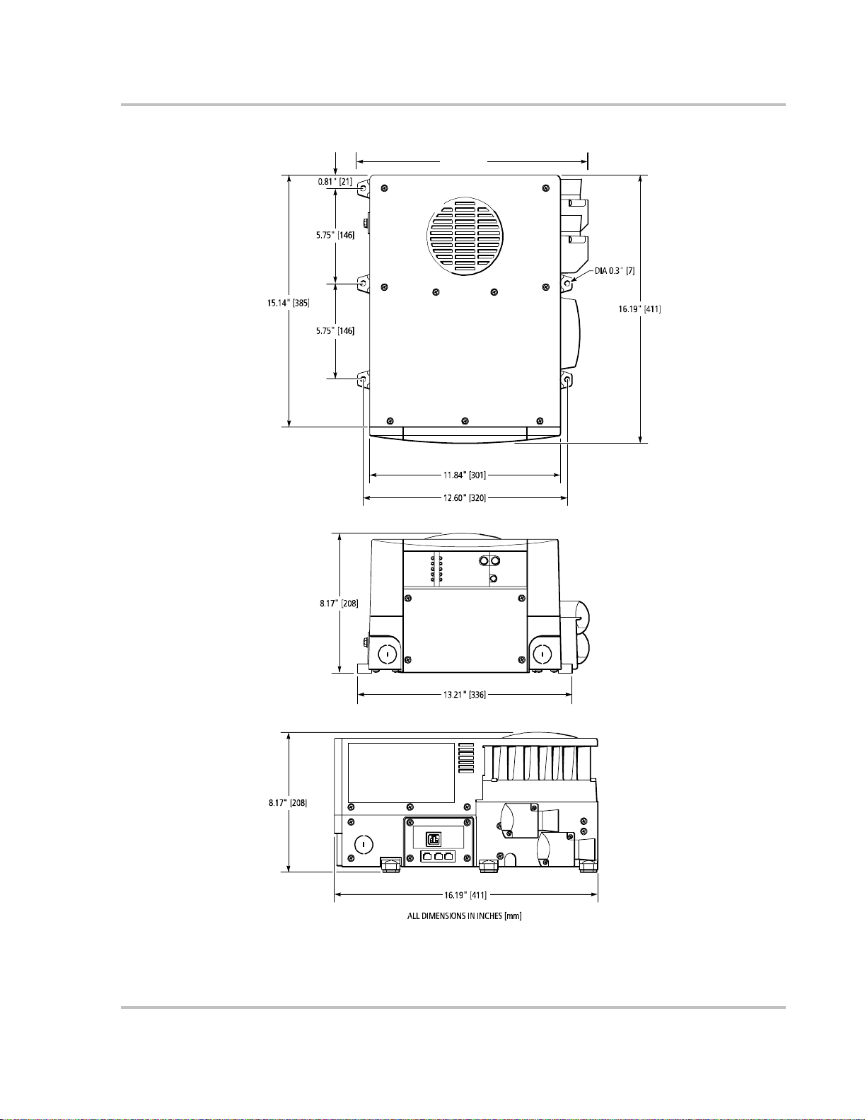
14.2" [361]
Installation
Figure 18
Inverter/Charger Dimensions
975-0126-02-01 39
Page 58

Installation
Battery Information
“Batt ery Information” discusses the physical make-up and characteristics of
chemical storage batte r ies and will help you to understand the factor s involved in
battery select ion, char ging, care, and mai ntenance . This infor mation is a guideline
only. The manufacturer of each battery is the best authority on its use and care.
Terminology
A description of battery charger operation requires the use of terms that you may
not be familiar with. The following terms appear throughout the guide.
Deep Cycle A deep cycle occu r s when a batt ery is d ischarged to less than 50% of its capacity (50% depth of discha rge). A deep-cycle battery is one that is intended to be deeply discharged and charged repeatedly.
Depth of Discharge (DOD) The amoun t of energy or charge removed from the battery bank, usually expressed as a percentage . A depth of discharge of 0% indicates a fully- charged battery , and a depth of discharge of 100% indicates a fully-discha rged battery.
Electrolyte Typically sulfuric acid and water. It is commonly referred to as battery acid, and it is the fluid inside a typical lead-acid battery.
Equalization A deliberate overcha r ge designed to reduce sulfation and stratificati on in floode d (or wet) lead- acid bat teri es. Not nec essary and ha rmful on Gel or sealed batteries.
Plates Made of lead and connected to the battery ter minals. These are the terminals inside eac h cell of the battery. The essential chemical reactions of the battery occur at the plates, a nd they are the source of the curr ent/vol tage produc ed by the battery.
Sulfation As a battery disch arg es, its plates beco m e co ve red w ith lead sulfat e. With regular recharging, the lead sulfate leaves the plates and recombines with the electrolyte. If the lead sulfate remains on the plates for an extended period of time (over two months), it hardens, a nd recharging does not remove it. Sulfation reduces the effective plate area and the battery’s capac ity. Equalization of flooded (or wet) batteries helps to redu ce sulfation.
Stratification Over time, electrolyte tends to separate. The electrolyte at the top of the battery becomes watery while it becomes more acidic at the bottom. This effect is corr osive to the plates. Equalization of flooded (or wet) batterie s helps reduce stratific ation.
Temperature Compen s a tion Optimal battery cha rgin g voltage is depende nt on the battery temperatur e . As the ambient temperature falls, the proper voltage for each charge stage needs to be increased. When the ambient temperature increases, the proper voltage for each charge stage needs to be decreased. (The BTS allows the inverter/ch arger to automatically rescale charge-voltage settings to compensate for ambient temperatures.) The hot, cold, and warm settings are used if a battery temperature sensor is not present. The hot setting is the default.
40 975-0126-02-01
Page 59

Battery Types
Starting Batteries
Installation
For the purposes of this discussion, there are two principal types of batteries:
starting and deep-cycle. Batteries are either sealed or vented. However, there are
even different kinds of these batteries. This section explains some of the
differences among lead-acid batteries to help you choose a battery that best suits
your needs.
Your MS2000 Sine Wave Inverter/Charger is designed for use with deep-cycle,
lead-acid batteri es . Thes e b atte ri es are d esign ed for d eep disch arge se rv ice w h ere
they will be repeatedly charged and discharged. This type of battery is often
labeled as a marine, recreat ional vehicle, or golf car t battery . Xantre x recommends
that you use one or more deep-cycle batteries separated from the starting battery
of your vehicle or boat.
Do not use starting batteries with your inverter; they will wear out rapidly in a
deep-cycle application. The way they are rated gives a good indication of their
intended use: “Cold Cranking Amps” is a me asure of the amperage output of a
battery intended for sta rting or “cranking” an engine.
Starting batteries use many thin plates to maximize the surface area of the battery.
This allows ve ry hig h start i ng curren t . In a deep cy cle ap p lic ation , thes e bat teri es
will limit the number of c ycles tha t can be supported be for e the ba tter y needs t o be
replaced.
Deep Cycle Batteries
Deep-cycle batteries are best suited for use with inver ters. They are designed to
have the majority of their capa city used before being recharged. Avail able in
many sizes and types, the most common is the non-seal ed, liquid electrolyte type
referred to as a “flooded (or wet) ” battery, commonly used in both boats and RVs.
Non-sealed types have removable battery caps. The caps should be removed at
least monthly so the electrolyte level can be checked. When a cell is low, only
distilled water should be added. “Spring” water and regular tap water may have
high mineral levels which can poison the battery chemistry and reduce battery
life.
Deep-cycle, lead-acid batteries can be grouped into five categories:
• Flooded (or wet)
• Sealed flooded (“maintenanc e free”)
• Recombinant flooded (ofte n “starve d electrolyte”)
• Gel batteries
• AGM
975-0126-02-01 41
Page 60

Installation
Sealed G el-Cell
Another popular and inexpensive battery of this type is the “golf cart”
(T-105 or CG220 or US 2200) b attery. These si x-volt batte ries can be con nected i n
series to form a 12 V system and can be discharged repeatedly to 80% of their
capacity without being se verely damaged. This is the minimum quality of battery
that should be used with the invert er in normal applications.
Some systems use the L16 type of battery. These are 6-volt batteries rated at
350Ah and are available from a number of manufacturers. They are 17 inches
(43 cm) high and weigh up to 130 pounds (60 kg) each — which may be
troublesome in some installations.
T ype 8D batteries are availabl e in either cranking or deep-cycle construction. The
deep-cycle versions are 12-volt batteries rated at approximately 200 Ah. Since
they are mostly commonly used to start tr uck engine s, you should make sure you
purchase the deep-cycle version, not the cranking version. Type 4D batteries are
very similar in construc tion but are somewhat smaller (approximately 170 Ah).
Another type of deep-cycle battery is the sealed gel-cell. The electrolyte is in the
form of a gel rather than a liquid and never requires topping up. Battery caps are
not removable. The sealed constr uction allows the batteries to be mounted in any
position without spil ling. The advantages are no maintenance to the battery itself
(the system sti ll requir es r outine mai ntenance) , long lif e ( 800 cycle s claimed) , and
low self-dischar ge. The disadvantages are high initial cost and the possibility of
damage from overcharging.
While many manufacturers prod uce qual ity flooded (or wet) batteries, only a few
produce suitable gel-cells. Don’t confuse gel batteries with maintenance-free
batteries, which are typically standard flooded (or wet) electrolyte batteries
without caps for adding water, and when the electrolyte gets low, you replace the
battery.
AGM (absorbed glass mat) batteri es are similar to gel-cells and deep-cycle types
and can be used in inverter applications.
Environment
For long life and good performance, batteries need to be located in a protected,
ventilated en clo s ure ins ul at ed fro m t emperature extrem es .
Location
Batteries should be located in an accessible loc ation that allow s for access to the
battery caps and terminal s. At least 12 to 18 inches of clearance above the
batteries is recommended. They must be located as close as possible to the
inverter/charger to keep the cable run short. However, do not locate the batteries
in the same space as the inverter/charger unless the y are of the sealed gel-cell
type.
42 975-0126-02-01
Page 61

Enclosures
Temperature
Installation
Batteries mus t be protected inside a ventilated enclosure. The enclosure should be
ventilated to the outdoo rs from the highest point to prevent the accumul ation of
hydrogen gases releas ed in the char ging process. An air intake should also be
provided at a low point in the enclosur e to allow air to enter the enclosure to
promote good ventilation.
Effect of cold
temperature
Benefits of
insulated enclosure
Protect batteries
from high
temperature
The effective capacity of a battery is reduced when the temperature is cold. This
phenomenon is more significant with lead-acid type batteries than with alkaline
types. When the internal tempera ture of a lead-acid battery is 32 °F (0 °C), the
capacity can b e redu ced by as much as 50% . This effec tivel y redu ces the siz e of
the system’s “gas tank,” requiring more frequent “refueling” by the charger. This
should be considered when you design the system. If extre mely low temperatures
are expected where the system is going to be located, a heated equipment room
should be considered.
If the system is located in an unheated space, an insulated enclosure is highly
recommended for the batteries. During the charging process, the batteries release
heat due to the internal resistance of the battery. If the batteries are insulated, the
heat can be kept in the batteries to keep them warmer. This will substantially
increase the performance of the system.
Insulated bat tery e nclosur es also ensu re that the t emperatur es of i ndivi dual ba tter y
cells are m ore cons istent. This p reve nts une qual c hargi ng, which ca n ca use batte ry
failure (some cells being overcharged while others are undercharged).
The batteries should als o be protected from high temperature. This can be caused
by high ambient temperatures, solar heating of the battery enclosure, or heat
released by an engine or generator located close by. High battery temperature
results in short battery life and shou ld be avoided by ventilating the enclosure and
reducing the external heat sour ces by shading and insulation.
975-0126-02-01 43
Page 62

Installation
Battery Bank Si zing
Purchase as much
battery capacity as
possible
Battery capacity A number of different sta nda rds are used to rate battery energy storage capacity.
Battery size or capacity is just as important as the battery type selected for use
with your MS2000 Sine Wave Inverter/Charger. The batteries are the most
important part of your system, so Xa ntre x recommends t hat you purcha se as much
battery capacity as possible. A large battery will extend running time and ensure
that your inverter/charger delivers full rated surge. Your inverter/charger can be
configured to work with batter ies from 50 Ah (120 reserve minutes) to 2000 Ah
(4800 reserve minutes).
Automotive and marine starting batteries are normally rated in cranking amps.
This is not a relevant rating for continuous loads like an inverter. Deep-cycle
batteries use a more suitab le rating system, either amp-hours (Ah) or “reserve
capacity” in minutes. Battery reserve capacity is a measure of how long a battery
can deliver a certain amount of curre nt—usually 25 amps.
For example, a batte ry with a reserve ca pacity of 18 0 minutes can deliver 25 amps
for 180 minutes before it is completely discharged. Amp-hour capacity is a
measure of how many amps a battery can deliver for a specified length of time—
usually 20 hours.
A typical marine or RV battery rated for 100 Ah can deliver 5 amps for 20 hours
(5 A × 20 hours = 100 Ah). This same battery can delivery a higher or lower
current for less or more time, limited approximately by the 100 Ah figure (50 A
for 2 hours or 200 A for 1/2 hour), but usually the capacity f igure given is only
accurate at the specified rate (20 hours).
The minimum battery size you can use with the MS2000 Sine Wave Inverter/
Charger is 50 Ah. However, you can expect performance to suffer with such a
small battery. Even if your battery is in excellent shape and is fully charged, you
will likely exper ience poor sur g e power performa nce and unsatisf act ory operating
time with anything but a small AC load. Xantrex recommends a minimum
battery size of 200 Ah for moderate loads (<1000W) and greater than 400 Ah
for heavy loads.
44 975-0126-02-01
Page 63

Estimating Battery Requirements
To determine the proper battery bank size, you need to compute the number of
amp-hours that will be used between charging cycles. When the required amphours are known, size the batteries at approximately twice this amount. Doubling
the expected amp-hour usage ensures that the batteries will not be overly
discharge d and extends battery life. To compute total amp-hour usage, deter mine
the amp-hour requirements of each appliance that is to be used and then add
together, or the watt-hours can be totaled and converted to amp-hours.
Start with the namepla te rating of your applia nces. I f the wattage is marked on the
appliance, you can use that number directly. Otherwise, multiply the marked
voltage and amperage: WATTS = VOLTS × AMPS.
Once you know the AC watta ge drawn from the inverter , multiply that amount by
the length of tim e the appliance will be used to determine the energy the load will
require: WATT-HOURS = WATTS × HOURS. You can then convert this to an
estimate of the battery amp-hours that the appliance requires.
BATTER Y AMP-HOURS USED = AC WATT-HOURS/10 (for a 12-volt battery)
—or—
BATTER Y AMP-HOURS USED = AC WATT-HOURS/20 (for a 24-volt battery)
For example, a 100 W light bulb that is used for 4 hours will use 400 watt-hours
(Wh) and the inverter will consume approximately 40 Ah from a 12 volt battery,
or 20 Ah from a 24 volt battery.
Installation
Another useful rule of thumb is that the current drawn from the battery can be
estimated from the AC output watts by using these same factor s (10 for 12-volt
systems, 20 for 24-volt systems). For example, when running an 800 W
microwave oven, the inverter will draw approximately 800 divided by 10 = 80 A
from a 12-volt battery.
Motors are normally marked with their running current rather than their starting
current. Starting current may be three to six times the running current. The
specification tha t is important in determining whether an inverter will start the
motor or not is the locked rotor amps. This specif ication may be abbreviated to
LRA or LRI. In gen era l, if the surge capa b ility o f the inv e rt er is in exces s of the
listed LRA, the inverter will start the motor. The MS2000 can surge to 5000 VA
for 5 seconds; this means that the MS2000 should be able to start a motor with an
LRA of less than 40 A.
If large motors will be starte d, you may need to increase the battery size to allow
for the high start-up demand.
975-0126-02-01 45
Page 64

Installation
Battery Bank Sizing Example
The following b attery s izing e xample i llus trates a typic al cal culation, assumi ng an
opportunity to charge the battery every three days:
Table 1-1
Appliance
TV & VCR 200 W 2 hours 400 Wh
Small microwave
oven
3 lamps, 60 W
each
Coffee maker 600 W 15 min = 1/4 hour 150 Wh
Hair dryer 1500 W 6 min = 1/10 hour 150 Wh
Battery Ah used between charges (divide by 10 for 12 volt system;
Battery Sizing Example
Daily watt-hours needed
(A) P ower
Con sumpt ion (Watts)
800 W 15 min = 1/4 hour 200 Wh
180 W 4 hours 720 Wh
Total daily watt-hours of AC load 1620 Wh
× Number of days between charges 3
= Total watt-hours of AC load between char ges 4860 Wh
divide by 20 for 24 volt system)
Recommended Battery Bank Size in Ah (multiply by 2) 972 Ah
(B) Operating Time
per D ay (Ho urs)
for this appliance
(= A × B)
486 Ah
This example illustra tes how quickly your battery needs can escalate. To reduce
the required batter y bank size, you can either conserve energy by eliminating or
reducing the use of some loads, or rechar ge more frequently.
When sizing your batt ery, be conservative and resi st the te mptat ion to skip the last
step of this calculati on (multiplying by 2). More capacity is better since you will
have more reserve capacity, be better able to handle large loads and surge loads,
and your battery won’t be discharged as deeply. Battery life is directly dependent
on how deeply the batter y is discharged. The deeper the discharge, the shorter the
battery life.
As your power requir ements increase, you may need to use more than one battery
to obtain sufficient capacity . Batteries can be connected in parallel, in series, or in
series-parallel to create higher capacity systems. It is not recommended to connect
batteries from dif ferent manufacturers, different types, or that have different amphour ratings in parall el. Improper charging and decreased battery life will resu lt.
See “Cabling & Hook-up Configurations” on page 52 for more information about
battery inter-connection schemes.
46 975-0126-02-01
Page 65

Battery Bank Sizing Worksheet
The following worksheet is a guide to hel p you determine your battery needs. Be
generous in est imating the time for which you will run each of the loads to ensure
sufficient battery capacity.
Installation
Table 1-2
Appliance
Battery Ah used between charges (divide by 10 for 12 volt system;
Battery Sizing Worksheet
(A) P ower
Con sumpt ion (Watts)
Total dail y wa tt -hour s o f A C load W h
× Number of days between charges
= Total watt-hours of AC load between charges Wh
divide by 20 for 24 volt system)
Recommended Battery Bank Size in Ah (multiply by 2) Ah
(B) Operating Time
per D ay (Ho urs)
W hours Wh
W hours Wh
W hours Wh
W hours Wh
W hours Wh
W hours Wh
W hours Wh
W hours Wh
Daily watt-hours needed
for this appliance
(= A × B)
Ah
975-0126-02-01 47
Page 66

Installation
Monthly Batter y Maintenance
Read the section “Personal Precautions When Working With Batteries” on
page vii prior to working on batteries.
WARNING: Risk of acid burns
Wear appropriate clothing, eye protection, and rubber gloves when carrying out
battery maintenance activities
WARNING: Risk of fire, explosions, burns
Use caution when wearing jewellery or working with metal tools around
batteries. Do not allow any metal object to contact both battery te rminals at the
same time. Batter y explosion or failure can occur.
❐ Check electrolyte levels in flooded (or wet) batter ies.
Flooded (or wet), lead-aci d batteries require periodic water refills in each
battery cell. Check the level of the electrolyte in each battery cell at least once
a month. The level should be above the top of the plates, but not completely
full. (Most batteries have a plastic cup that just touc hes the electrolyte when
the cell is full.)
Refill the batterie s with distilled water only. “Spring” water and regular tap
water may have high mineral levels which can poison the battery chemistry
and reduce battery life.
When filling the battery, clean the surface first to prevent dirt from entering
the cell. Fill the cell to just above the plates.
Don’t overfill the batteries, or the electrolyte will leak out when the batteries
are being charge d.
Check the water level in the batteries fre quently whe n performing an equaliz e
charge and add water if necessary.
❐ Check battery connections for good c ontact with the t ermi nals. See “Checking
battery connecti ons” on page 50.
❐ Maintain battery terminals. See “Reducing corrosion on battery terminals” on
page 51.
❐ Check specific gravity with hydrometer.
Make sure readings are in accordance with the battery manufactu rer’s
specifications.
48 975-0126-02-01
Page 67

Preparation for Cleaning Batteries
Dirty batteries can le ak curre nt and tend to run hotter. Ultimately , this affects the
performance of your inverter/charger, resulting in inefficient inverting and
incomplete charging. Cleaning batteries when necessary is easy and safe when
you follow these instructions.
Gather what you need before beginning the proce dure. The appropriate clothing,
tools, equipment, and supplies are listed as follows.
Clothing
Appropriate clot hing could inc lude ol d clothe s, rubbe r boots, or old shoes. Batter y
acid is high ly corr osive, so wea r somethi ng you can d isc ard just in c ase you s pla sh
some acid on yourself. Be sure to wear rubber gloves and eye protection.
Tools
❐ Adjusta ble wrench or appropriately sized ratchet and sockets for battery
terminals
❐ Adjustable and/or locking pliers
Installation
Equipment
Supplies
❐ Torque wrench (suggested, not required)
❐ Soft-bristled brush (a discarded toothbrush works fine)
❐ 6" scrub brush
❐ Inexpensive 1/2" chip brush or soldering brush
❐ Hydrometer
❐ Eye protection
❐ Rubber gloves
❐ Water hose with spray nozzle or five gallon watering bucket
❐ Empty spray bottle
❐ Baking soda (Always keep on hand in the event of a spill.)
❐ Hand cleaner or soap
❐ Towel
❐ Liquid neoprene or white lithium gre ase (Available at auto moti ve parts s tores ,
battery suppliers, RV and marine stores.) Use only after reattaching cables.
975-0126-02-01 49
Page 68

Installation
Maintaining and Cleaning
Follow the appropriat e procedur es for maintaining and cle aning the:
• battery enclosur e
• battery terminal and cable lug s
• battery cables
WARNING
Review the “Important Safety Instructions” on page v before you begin.
Battery Enclosure and Batteries
The battery enc losure s hould be cl eaned as r equir ed; for exa mple, if you se e liqui d
on the battery. Also wipe off the top of batteries.
Mix four ounces of baking soda with a gallon of fresh water. Fill a spray bottle
with the solution. Spray the solution on all exposed surfaces of the battery
compartment, and wash down the exposed surfaces of the batteries and their
enclosure. Scrub stubborn areas with the scrub brush. Baking soda will neutralize
any acid that may have collected on these surfa ces. Finish by rinsing with water.
Terminals & Lugs
Checking battery
connections
Periodically check the battery connections for corrosion and tightness of battery
terminals and cable lugs. Check ever y time you perform battery maintenance.
Loose battery terminals and cable lugs exposed to open air corrode rapidly. The
corrosion appears a s a white powder or granul ar foam on the terminals a nd on any
nearby exposed m etal parts. This is actually a crystallized form of sulfuric acid. If
the corrosive contacts your skin, it will cause burns unless you rinse it off
immediately. Most textiles that are exposed to this corrosive eventually dissolve.
The most common cause of battery system failure is loose or corroded battery
terminals and cable lugs. If any white powdery residue forms between the batte ry
cable lug and the b atte ry ter mi nal , rem ov e the ca ble fo r cl eani ng . Wh en it is
necessary to detach a battery cable from the battery, disconnect all loads and
charging sour ces. Using the appr opriate tool, remo ve the negative (–) batt ery cable
first and re-ins tal l it last.
To remove any stubborn residue, sprinkle baking soda directly on the area, and
scrub with a wet toothbrush ( or other soft-b ristle brush) . Ensure that all caps are on
tight so the solut ion doesn’t enter the battery. Add water as required and the n rinse
the top of the battery with clean water.
50 975-0126-02-01
Page 69

Installation
Reconnect the battery cable terminals to the battery cable lugs and tighten to
battery manufacture r’s specifications. If you do not have a torque wrench, use an
appropriate tool to tighten the bolts reasonably snug. Do not over-tighten.
Reducing corrosion
on battery terminals
Battery Cables
After tightening the cables, evenly coat all of the exposed metal surfaces of the
battery terminals and cable lugs with liquid neoprene (liquid electrical tape). Do
not apply anyt hing bet ween th e battery termina l and t he cable l ugs; the connecti on
should be metal to metal.
The liquid neoprene cures to form an airtight protective layer and reduce the
amount of corrosion on the batter y termi nals. If liquid neoprene is not available,
use a light coating of white lith ium grease or other sealant.
Inspect all of the battery cables for missing or damaged insulation or loose
connections. Inspect any openings that the cables pass through. All such openings
must be equipped with a rubber grommet or conduit to prevent chafing on the
battery cable . If ne cessary, replace wor n grommets. If t he cable i nsula tion is wo rn,
replace the battery cables.
975-0126-02-01 51
Page 70

Installation
Cabling & Hook-up Configurations
Several smaller batt erie s can be connected to create a batte ry bank of subs tantial
size. You can connect batteries in three ways: in parallel, series, or series-parallel.
T o make a lar ger batte ry bank, conne ct ind ividual b att eries wi th hea vy cables . The
actual size of the cable depen ds on whether the batteries are connected in parallel
or series. Generally, the cable should not be smaller than the inve rter cables—if
the main cables are 4/0 AWG, the battery interconnects should be 4/0 AWG.
The best configuration is to connect the batteries in series and parallel. This
requires additiona l cables, but reduces imbalances in the battery bank and can
improve the overall performance. Consult your battery supplier for more
information regarding the hook-up configuration required for your system.
Parallel Connection
Batteries are connected in parallel when all the positive terminals of a group of
batteries are connected and then, separately, all the negative terminals are
connected. In a parallel configura tion, the battery bank has the same voltage as a
single battery, but an Ah rating equal to the sum of the individual batteries. See
Figure 19.
Figure 19
52 975-0126-02-01
Batteries Connected in Parallel
Page 71

Series Connection
Installation
When batteries are connected with the positive terminal of one battery to the
negative terminal of the next battery, they are connected in series. In a series
configuration , the battery bank has the same Ah rating of a single battery, but an
overall voltage equal to the sum of the indiv idual batteries. See Figure 20.
Figure 20
Batteries Connected in Series
975-0126-02-01 53
Page 72

Installation
Series-Parallel Connections
As the name series-parallel impl ies, both the serie s and paral lel config urations are
used in combina tion. The result is an increase in both the voltage and the capacity
of the total battery bank. This is common with all battery-inverter system
voltages. The s ma ller, lower vol t age ba tte ri es are fir s t conn ected in s eries to
obtain the necessary volta ge, and then these “batteries connected in series” sets
are connected in parallel to increase the battery ban k capacity. See Figure 21.
Figure 21
54 975-0126-02-01
Batteries in Series-Parallel Connections
Page 73

Index
A
AC and DC wiring separation 20
AC circuit breaker 8
AC disconnect devi ce 8
AC fuse 8
AC input wiring connections 21
AC input, defined 8
AC knockout dimensions 20
AC output neutral bonding 9
AC output wiring connections 22
AC wiring 9, 20
AC wiring compa r tment, illustra ted 20
AC wiring terminal, illustrated 20
American Boat and Yacht Counc il (ABYC) 2, 12
B
baking soda 49
batteries
effects of temperature
estimati ng capacity requireme n ts 45
monthly maintenance 48
parallel connection 52
requirements 11
series connection 53
series-parallel con n ection 54
terminology 40
battery temperature sensor
cable length
connecting to Battery T emp. jack 33
function of 31
mounting on negative battery terminal 32
mounting to batte ry case 34
BTS. Se e ba tt er y tempera tu r e sensor 31
31
43
C
Canadian Electrical Code (CEC) 2
Canadian Standards Association (CSA) 2
clearance around unit, recommended 16
connecting t o the ne twork 35
Customer Service contact information iii
D
DC cables
preparing
23
required size and length 12
DC cabling, required 11
DC disconnect device 11
DC fuse size 12
DC grounding 12
DC over-current device 11
deep-cycle batteries 40, 41
distilled water 48
E
Echo Charger
cable length and s ize
connecting 29
fuse size 12
testing 38
electrolyte 40
electrolyte level 48
equalization 40
12
F
FCC, regulations viii
fuse
AC
8
DC 12
Echo Charger 12, 30
G
GFCI
models tested
requirements 8
ground cable
connecting
preparing 23
ground fault circui t interrupter. See GFCI. 8
8
28
H
hydrogen gas 17
I
installation
approved mounting orientations
approved mounting orientations, illustrated 19
choosing a location for inverter/charger 16
18
Page 74

Index
connecting AC input wires 20
connecting AC output wires 20
connecting battery temperature sensor (BTS) 31
connecting BTS cable to BTS jack 34
connecting cables to inverter/charger 25
connecting DC cables 23
connecting Echo Charger 29
connecting network 35
DC grounding 28
materials required 14
mounting the inverter/charger 18
overview 15
performing checks pr ior to initial start-up 36
routing DC cables 24
testing Echo Charger 38
testing in AC bypass mode 38
testing in charge mode 37
testing in invert mode 37
tools required 14
installation codes 2
invert er sp ecifica ti o ns 38
inverter/charger, heavy load precaution 18
K
key performance factors 5
S
seale d g el - ce ll bat t er ies 42
series battery connection 53
series-parallel batt ery connectio n 54
specifications 38
starting batteries 41
strain relief 14, 20
stratification 40
sulfation 40
T
temp erat u r e co mp ensatio n 40
tools required for installation 14
U
United States Coast Guard electrical r egulations 2
V
ventilation openings, recommended clearance 16
X
Xantrex, web site iii
L
liquid neoprene 49, 51
lithi u m gr e a se 49
M
maintaini ng batteries 48
mate r ia ls li s t 13
materials required for in stallation 14
mounting orientations 18
P
parallel battery connection 52
physical specifications 38
plates 40
preparing Echo Charger cable 29
preparing ground cable 23
R
related produc t literature iii
56 975-0126-02-01
Page 75

Page 76

Xantrex Technology Inc.
1 800 670 0707 Tel toll free NA
1 360 925 5097 Tel direct
1 800 994 7828 Fax toll free NA
1 360 925 5143 Fax direct
customerservice@xantrex.com
www.xantrex.com
975-0126-02-01
Printed in Canada
 Loading...