

Page 1

HI400
Owner’s Guide
Page 2

About Xantrex
Xantrex Technology develops, manufactures, and markets advanced power
electronic products. The company’s products convert raw electrical power from
any source into high-quality power required by electronic and electrical
equipment.
Trademark
Xantrex is a registered trademark of Xantrex Technology Inc.
Other trademarks, registered trademarks, and product names are the property of
their respective owners and are used herein for identification purposes only.
Notice of Copyright
HI400 Owner’ s Guide © January 2002 Xantrex International. All rights reserved.
Disclaimer
UNLESS SPECIFICALLY AGREED TO IN WRITING, XANTREX
TECHNOLOGY INC. (“XANTREX”):
(a) MAKES NO WARRANTY AS TO THE ACCURACY, SUFFICIENCY OR
SUITABILITY OF ANY TECHNICAL OR OTHER INFORMATION PROVIDED IN
ITS MANUALS OR OTHER DOCUMENTATION.
(b) ASSUMES NO RESPONSIBILITY OR LIABILITY FOR LOSS OR DAMAGE,
WHETHER DIRECT, INDIRECT, CONSEQUENTIAL OR INCIDENTAL, WHICH
MIGHT ARISE OUT OF THE USE OF SUCH INFORMATION. THE USE OF ANY
SUCH INFORMATION WILL BE ENTIRELY AT THE USER’S RISK.
Date and Revision
January 2002, Revision 2
Part Number
445-0151-01-01
Contact Information
Web: www.xantrex.com
Email: techhelp@xantrex.com
Phone: 1-800-446-6180
Fax: 1-360-925-5143
Page 3

Contents
Important safety information
General precautions - - - - - - - - - - - - - - - - - - - - - - - - - - - - - - - - v
Explosive gas precautions - - - - - - - - - - - - - - - - - - - - - - - - - - - vi
Precautions when working with batteries - - - - - - - - - - - - - - - - - vii
Precautions for using rechargeable appliances - - - - - - - - - - - - viii
1Introduction
Introduction - - - - - - - - - - - - - - - - - - - - - - - - - - - - - - - - - - - - - 2
HI400 features - - - - - - - - - - - - - - - - - - - - - - - - - - - - - - - - - - - 4
Materials list - - - - - - - - - - - - - - - - - - - - - - - - - - - - - - - - - - - - - 6
2 Installation
Preparing for installation- - - - - - - - - - - - - - - - - - - - - - - - - - - - - 8
Installation codes - - - - - - - - - - - - - - - - - - - - - - - - - - - - - - - - 8
Installation tools and mate rials - - - - - - - - - - - - - - - - - - - - - - - 9
Installation features - - - - - - - - - - - - - - - - - - - - - - - - - - - - - - 10
Installing the HI400 - - - - - - - - - - - - - - - - - - - - - - - - - - - - - - - 11
Overview- - - - - - - - - - - - - - - - - - - - - - - - - - - - - - - - - - - - - 11
Designing your installation- - - - - - - - - - - - - - - - - - - - - - - - - 11
Choosing a location- - - - - - - - - - - - - - - - - - - - - - - - - - - - - - 15
Mounting your inverter - - - - - - - - - - - - - - - - - - - - - - - - - - - 16
Permanently connecting (hardwiring) the AC output- - - - - - - - 17
Installing the ignition lockout wiring - - - - - - - - - - - - - - - - - - 18
Connecting the DC cables - - - - - - - - - - - - - - - - - - - - - - - - - 19
Connecting the battery to the DC input- - - - - - - - - - - - - - - - - 20
Connecting the DC ground - - - - - - - - - - - - - - - - - - - - - - - - - 21
i
Page 4

Contents
Connecting the AC input cord- - - - - - - - - - - - - - - - - - - - - - - 22
Checks prio r to initial power-up - - - - - - - - - - - - - - - - - - - - - 23
Starting up and testing your installation - - - - - - - - - - - - - - - - 23
3Operation
Operation features - - - - - - - - - - - - - - - - - - - - - - - - - - - - - - - - 26
Inverter on and off - - - - - - - - - - - - - - - - - - - - - - - - - - - - - - 26
Ground fault circuit interrupter (GFCI) protection - - - - - - - - - 26
Alternate AC source - - - - - - - - - - - - - - - - - - - - - - - - - - - - - 27
Ignition lockout - - - - - - - - - - - - - - - - - - - - - - - - - - - - - - - - 27
Low battery condition - - - - - - - - - - - - - - - - - - - - - - - - - - - - 27
Inverter loads - - - - - - - - - - - - - - - - - - - - - - - - - - - - - - - - - - - 28
Operating several loads at once - - - - - - - - - - - - - - - - - - - - - - 28
Problem loads- - - - - - - - - - - - - - - - - - - - - - - - - - - - - - - - - - 28
Turning the inverter off between charges - - - - - - - - - - - - - - - 29
Battery charging frequency- - - - - - - - - - - - - - - - - - - - - - - - - 29
4 Maintenance and Troubleshooting
Maintenance - - - - - - - - - - - - - - - - - - - - - - - - - - - - - - - - - - - - 32
Troubleshooting - - - - - - - - - - - - - - - - - - - - - - - - - - - - - - - - - 32
Common problems - - - - - - - - - - - - - - - - - - - - - - - - - - - - - - 32
Buzz in audio equipment - - - - - - - - - - - - - - - - - - - - - - - - - - 32
Television interference- - - - - - - - - - - - - - - - - - - - - - - - - - - - 32
Troubleshooting reference- - - - - - - - - - - - - - - - - - - - - - - - - - - 33
A
Specifications
Electrical - - - - - - - - - - - - - - - - - - - - - - - - - - - - - - - - - - - - - - 36
Physical - - - - - - - - - - - - - - - - - - - - - - - - - - - - - - - - - - - - - - - 36
B Battery Types and Sizes
Battery types- - - - - - - - - - - - - - - - - - - - - - - - - - - - - - - - - - - - 38
Automotive starting batte ries - - - - - - - - - - - - - - - - - - - - - - - 38
Deep-cycle lead-acid batteries- - - - - - - - - - - - - - - - - - - - - - - 38
Battery size- - - - - - - - - - - - - - - - - - - - - - - - - - - - - - - - - - - - - 39
ii
Page 5

Contents
Estimating battery requirements- - - - - - - - - - - - - - - - - - - - - - - 40
Battery sizing example- - - - - - - - - - - - - - - - - - - - - - - - - - - - 41
Battery sizing worksheet - - - - - - - - - - - - - - - - - - - - - - - - - - 42
Using multiple batteries - - - - - - - - - - - - - - - - - - - - - - - - - - - - 43
Two batteries connected in parallel - - - - - - - - - - - - - - - - - - - 43
Two separat e battery banks- - - - - - - - - - - - - - - - - - - - - - - - - 43
Battery tips - - - - - - - - - - - - - - - - - - - - - - - - - - - - - - - - - - - - - 44
C
Warranty and Product Information
Warranty information- - - - - - - - - - - - - - - - - - - - - - - - - - - - - - 48
Returning a product - - - - - - - - - - - - - - - - - - - - - - - - - - - - - - - 49
Out-of-warranty service - - - - - - - - - - - - - - - - - - - - - - - - - - - - 50
Contacting Xantrex Customer Service- - - - - - - - - - - - - - - - - - - 51
Other Xantrex products- - - - - - - - - - - - - - - - - - - - - - - - - - - - - 51
Index - - - - - - - - - - - - - - - - - - - - - - - - - - - - - - - - - - 53
iii
Page 6

iv
Page 7

Important safety information
Important: Before installing and using your HI40 0
Inverter, be sure to read and save these safety instructions.
General precautions
1. Before installing and using the inverter, read all
appropriate sections of this guide and any cautionary
markings on the inverter and batteries.
2. Do not operate the i nverter if it has rece ived a sharp bl ow ,
been dropped, or otherwise damaged. If the unit is
damaged, see “Service during warranty” on page 48 and
“Returning a product” on page 49.
3. Do not disassemble the inverter; it contains no user
serviceable parts. Attempting to service the unit yourself
could cause electrical shock or fire. Internal capacitors
remain charged after all power is disconnected. See
“Warranty information” on page 48 for instructions on
obtaining service.
4. To reduce the risk of electrical shock, disconnect both
AC and DC power from the inverter before working on
any circuits connected to the inverter. Turning off the
front panel On/Off Switch will not reduce this risk.
5. Protect the inverter from rain, snow, spray, and bilge
water.
6. To reduce the risk of overheating or fire, keep the
ventilation openings clear, and do not install the inverter
in a zero-clearance compartment.
v
Page 8

Explosive gas precautions
Explosive gas precautions
WARNING: Explosion hazard
.
1. Batteries generate explosive gases during normal
operation. Be sure you follow all relevant instructions
exactly before installing or using your inverter.
2. This equipment contains components which tend to
produce arcs or sparks. To prevent fire or explosion, do
not install the inverter in compartments containing
batteries or flammable materials or in locations that
require ignition-protected equipment. This includes any
space containing gasoline-powered machinery, fuel
tanks, as well as joints, fittings, or other connections
between components of the fuel system.
vi
Page 9

Precautions when working with batteries
Precautions when working with batteries
WARNING: Explosion and fire hazards
1. Follow all instructions published by the battery
manufacturer and the manufacturer of the equipment in
which the battery is installed.
2. Make sure the area around the battery is well ventilated.
3. Never smoke or a llow a spar k or fla me near the engi ne or
battery.
4. Use caution to redu ce the risk o f drop ping a metal tool on
the battery. It could spark or short circuit the battery or
other electrical parts and could cause an explosion.
5. Remove metal items li ke rings, bracelets, and watches
when working with lead-acid batteries. These batteries
produce a short-c ircuit curre nt high en ough to weld a r ing
or the like to metal and cause a severe burn .
6. If you need to remove a battery, always remove the
positive terminal from the battery first. Make sure all
accessories are off so you don’t cause an arc.
vii
Page 10

Precautions for using rechargeable appliances
Precautions fo r u sing rechargeable
appliances
Most rechargeable battery-operated equipment uses a
separate charger or transformer that is plugged into an AC
receptacle and produces a low voltage charging out.
Some chargers for rechargeable batteries can be damaged if
connected to the HI400 Inverter.
Do not use the following with the HI400 Inverter:
• Small battery-o perated a ppliance s like f lashli ghts, raz ors,
and night lights that can be plugged directly into an AC
receptacle to recharge.
• Some chargers for battery packs used in hand power
tools. These affected chargers display a warning label
stating that dangerous voltages are present at the battery
terminals.
viii
Page 11

Introduction
Chapter 1 “Introduction” describes the main
operating features of the HI400 Inverter.
1
Page 12

Introduction
Introduction
The HI400 Inverter is a modified sine wave (MSW) inverter
providing power for a variety of AC loads, such as TVs,
VCRs, laptops, camcorders and other small AC devices.
They are CSA certified for use in recreational vehicles.
The HI400 is available in two versions:
• “HI400 with hardwire” is designed for permanent
hardwired installation.
• “HI400 with hardwire and GFCI outlet” has a GFCI
receptable on the front and a hardwire compartment. It
provides easy access for plugging a load directly into the
output of the unit. The hardwire compartment allows the
unit to be installed permanently.
HI400 offers the following inverter features:
• Ability to run many of the entertainment loads that you
use at home.
You can operate TVs, stereos, VCRs, computers and
even small battery chargers. You can run multiple loads
up to 400 watts in total.
• Surge capability
HI400 will surge up to 550 watts peak.
• Low voltage shutdown
The inverter shuts off when your batteries discharge to
less than 10 volts.
When the battery voltage recharges to above 12.5 volts,
the inverter automatically restarts. Thi s feature prevents
the inverter from draining the batteries if it is left on
without a load.
• Ground fault circuit interrupter (GFCI)
As well as providing for per manent hard wire i nstallat ion,
the GFCI model provides a receptacle for plugging in a
load.
2
Page 13

Introduction
This receptacle has a “gro und fault circuit interrupter” to
reduce shock hazards on loads connected to both the
receptacle and hardwire outputs.
• Ignition lock out
Ignition lockout prevents the inverter from operating
while the engine is running. It allows the user to turn the
inverter on and off remotely.
• Transfer switch
Automatically connects the loads on the receptacle and
hardwire outputs to the external AC source when one is
available. Upon discon nection, or los s of the exter nal AC
source, the transfer switch automatically transfers the
load circuits over to inverter power.
3
Page 14
HI400 features
HI400 features
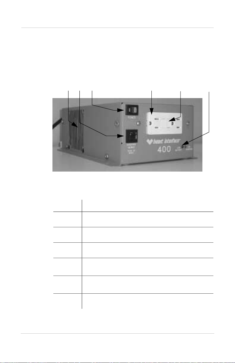
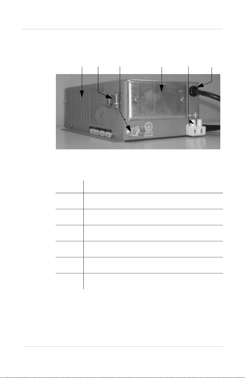
Figure 1 below, and Figure 2 opposite, show the front and
back panels of the HI400. Table 1 and Table 2 list the
respective panel parts.
➀➁
Figure 1 Front Panel - “Hardwire with GFCI” version.
Table 1 Front panel features
Feature Description
➀
➁
➂
➂
Fan vents
Output circuit protector
ON/OFF power switch
➃
➄
➅
➃
➄
➅
4
Dual AC receptacle (on the GFCI outlet and hardwire
version only)
GFCI test and reset buttons (on the GFCI outlet and
hardwire version only)
“On inverter” and “low battery status” LEDs
Page 15
HI400 features
➀
➁
Figure 2 Back panel
p
T able 2 Back panel features
Feature Description
➀
➁
➂
Air vents
Cable clamp
Chassis grounding lug
➂
➃
➄
➅
➃
➄
➅
AC hardwiring compartment (with cover on)
DC input terminals
AC input cord
5
Page 16

Materials list
Materials list
Your HI400 inverter package includes the items listed below:
❐ Inverter with hardwire (80-04 01-12) or
Inverter with hardwire and GFCI outlet (80-0400-12)
❐ Owner’s Guide
6
Page 17

Installation
Chapter 2 “Installation” provides complete
information for installing the HI400 Inverter.
Specifically, this section describes:
• safety instructions and installation codes
that must be observed during installation.
• installation tools and materials.
• appropriate locations and environments
for mounting the inverter.
• AC cabling, DC cabling, and ground
information.
• detailed installation procedures.
7
Page 18
Preparing for installation
Preparing for installation
Prior to beginning your installation, review the “Important
Safety Instructions” on page v, and read the entire
“Installation” section so you can plan your installation from
beginning to end.
WARNING: Electrical shock and fire
hazards
Xantrex recommends all wiring be done by qualified
personnel. Disconnect all AC and DC power sources to
prevent accidental shock. Disable and secure all AC and
DC disconnect devices and automatic generator starting
devices.
It is the installer’s responsibility to ensure compliance
with all applicable installation codes and regulations.
CAUTION
Be sure to read all instructions before installing and
operating this inverter.
Installation codes
Applicable installation codes vary depending on the specific
location and application of the installation. Some examples
are:
• T he U.S. National Electrical Code (NEC)
• The Canadian Electrical Code (NEC)
• NEC, Canadian Standards Association (CSA), and RV
Industry Association (RVIA) requirements for
installation in RVs.
It is the installer’s responsibility to determine which codes
apply, and to ensure that all applicable installation
requirements are met.
8
Page 19

Installation tools and materials
You will need the following tools and materials to install the
inverter:
❐ #2 Phillips screwdriver
❐ Wire stripper
❐ 4 mounting screws or bolts and appropriate tools
❐ 3/8” wide slot screwdriver for DC input and chassis
ground terminals
❐ 3-conductor (2-conductor-plus-ground cable) AC output
cable sized appropr iate ly for l oad accor ding to ap plicab le
installation code(s). In the NEC, CEC and RV
applications, this is No. 14 AWG.
❐ Crimp connectors and appropriate crimping tool for AC
output wiring and ignition lockout wiring (if twist-on
wire connectors are not appropriate for your installation).
❐ DC cable, sized appropriately for load per the applicable
installation code(s). In NEC, CEC and RV applications,
this is No. 8 AWG if copper conductors rated 60 °C –
90 °C are used.
Preparing for installation
❐ Terminals for connecting the DC cables to the battery, as
well as appropriate tools for those terminals (for
example, crimping tool, hex-key, etc.).
❐ AC and DC disconnects and over-current protective
devices.
9
Page 20
Preparing for installation
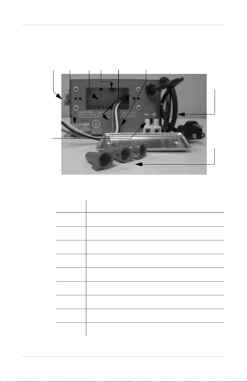
Installation features
Figure 3 and Table 3 below, list the installation features of
your HI400 inverter.
➁
➂
➃
➄
➅
➆
➀
Figure 3 Installation features: back view
T able 3 Installation features: back view
Feature Description
➀
➁
➂
DC input terminals
Cable clamp
Chassis grounding lug
➇
➈
10
➃
➄
➅
➆
➇
➈
AC Hardwire compartment
Ground screw for AC output ground
Ignition lockout wire (red)
AC output wiring (blac k, white)
AC input cord
Wire connectors (3)
Page 21

Installing the HI400
Overview
This section provides detailed installation information. The
overall procedure is divided into nine main steps:
Installing the HI400
Step 1
Step 2
Step 3
Step 4
Designing your installation (page 11)
Choosing a location for your inverter (page 15)
Mounting your inverter (page 16)
Permanently connecting the AC output wiring
(page 17)
Step 5
Step 6
Step 7
Step 8
Step 9
Installing the ignition lockout wiring (page 18)
Connecting the DC cables (page 19)
Connecting the AC input cord (page 22)
Checks prior to initial pow er-up (page 23)
Starting up and testing your installation
(page 23)
Designing your installation
This section provides information about AC wires, DC
cables, AC disconnects and over protection devices, GFCIs,
and batteries which you must supply as part of the
installation.
AC shorepower
A source of 120 volt, 60 Hz alternat ing curr ent (AC) power is
needed if it is desired to power the loads connected to the
inverter from a source other than the inverter. Typically, this
source will be utility grid (power company) power provided
at an RV park or campground, or an AC generator.
11
Page 22

Installing the HI400
Note:
AC input power from a utility grid, generator, or other source.
AC disconnects and over- current protection devices
Throughout this manual, the term “s horepower” r efers t o
To meet electrical code requirements, you must provide the
inverter with over-current protection (such as a circuit
breaker or fuse) and a disconnect device as follows:
AC Input: The circuit breaker or fuse used to protect the
HI400 inverter must be rated no more than 15 A and must be
approved for use on 120 Vac branch circuits.
AC Output: The circuit breaker or fuse must be rated at no
more than 15 A and must be approved for use on 120 Vac
branch circuits.
Disconnect devices: Each system requires a method of
disconnecting each AC circuit. If the over-current protection
device is a circuit breaker, it will serve as a disconnect
switch. If fuses are used, separate AC disconnect switches
will be needed between the source of power and the fuses.
AC output wiring
The type and size of the wires between the inverter output
and the loads varies with the installation type and applicable
codes. For many RV applications, flexible multi-strand wire
is required. Installation codes may specify solid or stranded,
overall size of the conductors, and type and temperature
rating of the insulation around the wire.
12
The AC output wiring must be sized to match the current
rating of the circui t breaker or fuse you pr ovide on AC outpu t
circuits. The size must be in accordance with the electrical
codes or regulations applicable to your installation. In most
NEC, CEC, and RV installations, the wire size will be
required to be No. 14 AWG, 3-conductor (line and neutral,
plus ground).
Page 23

AC output neutral bonding
The neutral conductor of the inverter’s AC output circuit is
automatically connected (“bonded”) to the safety ground
whenever the inverter is running and AC utility shorepower
is not present. When AC shorepower is present, this
connection is automatically lifted, as that same bonding
connection will b e presen t in the AC shorepower source. This
system automatically conforms to electrical code
requirements that neutral conductors are to be bonded to
ground at all times, but only in one place at a time.
CAUTION: Damage to unit
Do not connect AC output to any AC load circuit in which
the neutral conductor is connected to ground (earth) or to
the negative of the DC (battery) source. Doing so will
damage the unit.
DC disconnects and over-current devices
The DC circuit from the battery to the inverter must be
equipped with over-current protection (such as a circuit
breaker or fuse) and a disconnect device. This usually
consists of a DC-rated circuit breaker, a “fused-disconnect,”
or a separate fuse and DC disconnect. Do not confuse AC
circuit breakers with DC circuit breakers — they are not
interchangeable. The current rating of the fuse or breaker
must be matched to the size of the DC cables used in
accordance with the applicable installation codes. The
breaker or disconnect and fuse should be located as close as
possible to the battery, in the positive cable. Applicabl e codes
may limit how far the protection can be from the battery.
Installing the HI400
For No. 8 AWG DC cable, the fuse or circuit breaker is
required to be rated 40 Adc max. Use a sl ow-blow f use to ge t
the maximum surge performance from the inverter.
13
Page 24

Installing the HI400
DC cabling
This includes the DC cables between the battery, the DC
disconnect and over-current protection device, and the
inverter. For copper cable rated 60 °C, 75 °C, or 90 °C, the
minimum size cable allowed in NEC, CEC, or RV
installations is No. 8 AWG (assuming a 40 Adc fuse or
breaker is used).
Batteries
Every HI400 inverter requires a 12 V deep-cycle battery or
group of batteries to provide the DC current that the inverter
converts to AC. Deep-cycle batteries are intended to be
repeatedly cycled partly or fully discharged, and then
charged. Automotiv e-type st arting o r “cranking” batteri es are
not recommended, except for temporary emergency use,
since deep-cycle use will severely limit their useful life.
Ground fault circuit interrupters (GFCIs)
GFCIs are intended to protect people from electrical shocks
and are usually required in wet or damp locations. A regular
circuit breaker cannot provide this type of protection.
14
Installations in recreational vehicles require GFCI protection
of branch circuits connect ed to the AC output of the inverter .
The HI400 comes in two versions. In the version with the
integral GFCI receptacle, the GFCI protects both the
receptacle’s output and the hardwire output. In the version
without the integra l GFCI receptacl e, the hardwir e output has
no GFCI protection, and it is up to the installer to provide it.
Compliance with UL standards requir es tha t Xantre x test and
recommend specific GFCIs for use with the HI400 inverter.
Xantrex has tested the GFCI-p rotected 15 A recepta cles listed
in Table 4, and found they function properly when connected
to the AC output of the HI400.
Note:
instructions for testing and resetting your GFCI.
You should test your GFCI monthly. See page 26 for
Page 25

Table 4 Tested GFCI models
Manufacturer Model number
Leviton 6599
Pass & Seymour 1591
Hubbell GF 5252GYA
Choosing a location
WARNING: Risk of fire or explosion
This equipment contains components that tend to
produce arcs or sparks. To reduce the risk of fire or
explosion, do not install this equipment in compartments
containing batteries or flammable materials, or in
locations that require ignition-protected equipment. This
includes any space containing gasoline-powered
machinery, fuel tanks, or joints, fittings, or other
connections between components of the fuel system.
Installing the HI400
WARNING: Fire hazard
Do not cover or obstruct the ventilation openings. Do
not install this equipment in a zero-clearance
compartment. Overheating may result.
The inverter should only be installed in locations that meet
the following requirements:
Dry Do not allow water or other fluids to drip or
splash on the inverter. Do not expose to rain,
snow or splashing water.
Cool Normal air temperature should be between
32 °F and 77 °F (0 °C and 40 °C) — the
cooler the better within this range.
15
Page 26

Installing the HI400
Ventilated See the warning on page 15. Allow at least 5
Safe See the warning on page 15. Do not install
inches of clearance on each size of the
inverter for air flow. Do not allow the
ventilation openings on the unit to become
obstructed. Make sure the compartment in
which the inverter is installed allows airflow
through the compartment.
the inverter in the same compartment as
batteries or in any compartment capable of
storing flammable liquid s like gasoline.
Close to battery
compartment
and the AC
source and load
Protected from
battery acid and
gases
Mounting your inverter
The HI400 inverter must be mount ed f la t (f or exampl e, o n or
under a horizontal surface) in order to comply with safety
agency requirements.
To mount your HI400 inverter:
1. Turn the On/ O ff switch on the inverte r t o the off position.
2. Fasten the inverter to the mounting surface, using four
#10 pan head steel wood screw (5/8” long minimum) or
#10 bolts inserted through the mounting holes in the
flanges (running along the sides of the inverter).
Avoid excessive cable lengths (these reduce
input and output power due to wire
resistance). It is preferable to have lengthier
AC cables than DC cables, as the AC current
is far lower than the DC. Use the
recommended cable sizes.
Never allow battery acid to drip on the
inverter or its wiring when filling or reading
its specific gravity. Do not mount the unit
where it will be exposed to gases produced
by the batteries. These gases are corrosive
and prolonged exposure will damage the
inverter.
16
Page 27
Installing the HI400
Permanently connecting (hardwiring) the AC output
WARNING: Fire, shock, and energy
hazards
Make sure wiring is disconnected from all electrical
sources before handling. All wiring must be done in
accordance with local and national electrical wiring
codes. Do not connect the output leads of the inverter to
any incoming AC source.
To hardwire t he AC output connections:
1. Remove the AC hardwire compartment cover. Three
wires are located inside the w iring compartment as
follows:
• Black – the AC output line conductor
• White – the AC output neutral conductor
• Red – the ignition lockout conductor (page 18)
WARNING: Shock hazard
Do not connect the ignition lockout wire (red) to AC
circuits. See instructions for connecting on page 18.
2. Run No. 14 AWG 2-conductor-plus-ground cable
through the cable clamp and into the AC wiring
compartment.
3. Strip about 2 inches off the jacket of the AC cable.
4. Strip approximately ½ inch off the insulation of the black
and white wires from the AC cable (if using the twist-on
wire connectors provi ded). If you are p roviding your own
connectors, follow the manufacturer’s recommendations
regarding strip length and use of the connectors.
17
Page 28

Installing the HI400
5. Connect the bl ack and white ( line and neutral ) wires from
6. Connect the ground wire (bare or green) from the AC
7. Connect the load end of the AC cable to your system’s
the AC cable to the black and white wires located in the
HI400 hardwire compartment. Be sure to connect black
to black and white to white. Chec k to make sure the wir es
are making a good connection, and secure the twist-on
wire connectors with electrical tape.
cable to the green-headed screw on the back wall of the
hardwire compartment. Use a crimp-on ring terminal if
the AC input ground wire is stranded. Solid wire can be
secured directly under the head of the screw.
AC output circuit breaker, or the load distribution panel
depending on your system design.
WARNING: Shock hazard, risk of damage
Do not connect the HI400 Inverter output to AC
distribution wiring powered by any other source. Shock
hazard and damage may result.
Installing the ignition lockout wiring
The ignition lockout system turns the inverter off when the
ignition is on. The system is designed so that when a userapplied 12 V signa l is pr esent on the red i gnition lockout wi re
in the hardwire c ompartment, the inverter tu rns off . This 12 V
signal is normally obtained by connecting a wire to circuits
downstream from the vehicle ignition switch, so that 12 V is
present when the ignition is on, and not present when the
ignition is off. The circuit selected should be protected by a
fuse rated maximum 5 Adc.
To install the ignition lockout wiring:
1. Connect a min. No. 18 AWG wire to an appropriate,
fused 12 V ignition-switched circuit. In the following,
this wire is referred to as the “lockout signal wire.”
18
Page 29

Installing the HI400
2. Route the lockout signal wire through the cable clamp
and into the hardwire compartment.
3. Strip approximately ½ inch off the insulation of the red
ignition lockout wire an d the lockout sig nal wire (if usi ng
the twist-on wire connectors provided). If you are
providing your own connectors, follow the
manufacturer’s recommendations regarding strip length
and use of the connectors.
4. Connect the lockout signal wire to the re d ignition
lockout wire provided in the hardwire compartment.
Check to make sure the wires are making a good
connection, and secure the twist-on wire connector with
electrical tape.
5. Re-install the hardwire compartment cover plate.
6. Tighten the cable clamp so that the AC output cable and
ignition lockout wiring are secured. Check to make sure
the clamp is securing the overall jacket of the AC output
cable (not the individual conductors), and that no wiring
is being pinched in the corners of the clamp.
Connecting the DC cables
CAUTION
Before making the final DC connection, check cable
polarity at both the battery and the inverter. Positive (+)
must be connected to positive (+); negative (–) must be
connected to negative (–).
Reversing the positive (+) and negative (–) battery
cables will damage the inverter and void your warranty.
This type of damage is easily detected.
WARNING: Fire hazard
Use only appropriately sized copper wire. Make sure all
DC connections are tight. Loose connections will
overheat.
19
Page 30

Installing the HI400
Follow the procedures given below to connect the battery to
the DC input terminals. The cables should be as short as
possible and large enough to handle the required current, in
accordance with the electri cal codes or regula tions appl icable
to your installation. As noted above, the recommended cable
size is No. 8 AWG for compliance with NEC, CEC, and RV
codes (assuming a 40 amp DC fuse).
To ensure maximum performance from the invert er, do no t
route your DC cable s through a DC di stributio n panel, batt ery
isolator, or other device that will cause additional voltage
drops.
Connecting the battery to the DC input
To make the DC connections:
1. Cut the DC cables to the correct length with enough
insulation stripp ed off so you can prop erly install the type
of terminals you will be using at the battery end. At the
HI400 end, strip the wire 3/8 inch.
2. Assign one cable to be positive (+) and one cable to be
negative (–). Mark both ends of each cable to avoid
confusion during installation.
20
3. Switch the On/Off switch into the off position (if you
have not already done so).
4. Route the DC ca bles f rom the batt ery ba nk to t he inv erter.
5. Install a DC breaker or a fuse and disconnect in the
positive side of the circuit, as close as possible to the
battery. Turn off the breaker or open the disconnect
switch.
6. Attach the negative (–) cable to the negative (–) battery
terminal (or to the current shunt if a shunt is used) using
whatever connector you have selected. Tighten the
connection according to the manufacturer’s
recommendation.
Page 31

Installing the HI400
7. Insert the other end of the negative (–) cable into the
negative (–) terminal on the HI400 and tighten the
terminal screw. Ensure all strands of wire are inside the
connector (no stray st rands). The termi nal manufacturer’ s
recommended tightening torque is 21 inch-pounds.
8. Attach the positive (+) cable to the breaker or fuse and
disconnect combination installed on the battery positive
(+) terminal in step 5. Tighten the connection according
to the manufacturer’s recommendations.
9. Insert the other end of the positive (+) cable into the
positive (+) terminal on the HI400 and tighten the
terminal screw. Ensure all strands of wire are inside the
connector (no stray st rands). The termi nal manufacturer’ s
recommended tightening torque is 21 inch-pounds.
10. Verify the polarity of the DC connections is correct:
positive (+) on the inverter connected to the positive (+)
on the battery, and negative (–) connected to the
negative (–).
When you are ready to oper at e the inve rt er, close the DC
circuit breaker or disconnect switch to supply DC power
to the inverte r.
Connecting the DC ground
The chassis ground lug on the DC end of the inverter is used
to connect the chassis of the inverter to your system’s DC
grounding point as required by installation codes for some
installations.
Use copper wire that is either bare or provided with green
insulation. Do not u se t he DC gr oun d lug for your AC output
grounding wire (see the AC wiring instruc tions on page 12 in
this sectio n).
To connect the DC ground:
➢ Connect a No. 8 AWG copper wire between the HI400’s
chassis ground lug and the DC grounding point for your
system.
21
Page 32

Installing the HI400
In an RV or vehicle installation, this will usually be the
vehicle chassis or a dedicated DC ground bus.
Connecting the AC input cord
WARNING: Shock hazard
Connect the AC input cord only to a properly grounded
standard 120 Vac, 15 A receptacle. If the correct type of
receptacle is not available, have an electrician install
one.
To connect the AC input cord:
➢ Plug the AC input cord (loc ated at the bac k of the
inverter) into a properly grounded 120 Vac, 15 A
receptacle connected to an external shorepower source
such as a utility grid or a generator.
22
Note: Connecting the AC input cord to the AC output
receptacle on the HI400 GFCI version will not power loads and
will cause the unit to malfunction. There should not be any
damage.
When the shorepower AC source is supplied, the HI400 will
transfer the loads to the shorepower source and turn off the
inverter.
When the shorepower AC so urc e i s di sc onnected or fails, the
HI400 will automatically tur n on the inver ter and trans fer the
loads to inverter power.
Page 33
Checks prior to initial power-up
Before powering up your in verter , ensure these condit ions are
met:
❐ On/Off power switch is in the off position.
❐ Positive (+) battery cable is conn ect ed to the
positive (+) battery terminal.
❐ Negative (–) battery cable is connected to the
negative (–) battery terminal.
❐ Battery voltage is within the proper range for this unit
(10.0 – 15.0 Vdc).
❐ DC Fuse is intact (not blown).
Starting up and testing your installation
WARNING
The front panel power switch does not disconnect DC or
AC input power to the unit.
Installing the HI400
To turn on the HI400:
1. Turn the On/Off power switch on the fro nt panel to the on
position. The green ON INVERTER LED indicator
illuminates.
2. Plug a load into the GFCI receptacle on the front panel.
Apply a load of 400 watts or less.
3. Test the transfer feature by plugging the AC input cord
into the shorepower source receptacle.
The inverter will transfer with the power switch in either
the on or off position.
23
Page 34

24
Page 35

Operation
Chapter 3 “Operation” explains how to
operate the HI400 Inverter.
25
Page 36

Operation features
Operation features
CAUTION
Read all operating instructions before operating the
HI400.
Inverter on and off
The On/Off power switch on the front panel turns the HI400
inverter on or off:
• In the On position, the green inverter On LED indicator
illuminates and the unit begins inverting if AC
shorepower is not present . The HI4 00 is now operational
and you can apply a load requiring less than 400 watts.
• In the Off position, the inverter AC output is turned off,
but if AC shorepower is present, the hardwire and GFCI
outputs will be en ergi zed and l oads wil l operat e. W ith the
switch in the Off position, the unit does not draw any
battery power, except as required to run the fan until the
unit cools off.
Ground fault circuit interrupter (GFCI) protection
The GFCI with hardwire version contains a GFCI receptacle
that protects the hardwire output and the receptacle output
against a ground fault.
Correcting a ground fault
When a fault condition is detected, the reset button on the
GFCI receptacle pops out and power to the load is
interrupted.
To resume normal operation, determine and correct the
ground fault, then push the reset button in.
26
Page 37

Monthly testing
Once a month, with either AC shorepower or inverter power
present, press the test button on the GFCI receptacle. The
reset button should pop out. Push it to reset the GFCI, and
continue normal operation. This should be completed on a
monthly basis.
If the reset button does not pop out, the GFCI may have
failed. Disconnect AC and DC power to the unit and have a
qualified service person look at it.
Alternate AC source
An AC input cord is pro vided a t the back of the unit a llowing
for alternate source AC power. Plug the input cord on the
back of the HI400 into a shorepower receptac le. The load can
be run from the alternate source when it is present.
When the shorepower source is not present, the internal
transfer relay will automatically trans fer the load to in verter
power. This transfer relay functions whether the power
switch is in the on or off position.
Operation features
Ignition lockout
The inverter automatically shuts off when the ignition
lockout is engaged. This occurs when the power switch is in
the On position and a 12 vol t signa l (not t o exceed 16 Vdc) is
applied to the ignition lockout wire. Refer to page 18 for
details.
Low battery condition
When the low battery red LED light illuminates, the battery
voltage has dropped below 10.5 Vdc. When the battery
voltage drops below 10.0 Vdc, the inverter turns off to
prevent further discharging of the battery by the HI400.
27
Page 38

Inverter loads
Inverter loads
The HI400 will operate most AC loads within its power
rating (400 watts/3.3 amps).
Typical loads that can be used on the HI400 are as follows:
•Laptops
•Small TVs
• Handheld computing devices
• VCRs
• Camcorders
• Other light duty AC devices
Operating several loads at once
If you are going to operate se veral loads fr om the HI400, turn
them on separately af ter you ha ve turned t he inv erter on. Thi s
ensures that the inverter does not have to deliver the starting
current for all the loads at once. The HI400 can handle
several loads as long as they do not exceed 400 watts in total.
Problem loads
Some appliances may be damaged if they are connected to
the HI400:
• Electronics that modulate RF (radio frequency) signals
on the AC line will not work and may be damaged.
• Speed controllers found in some fans, kitchen app liances,
and other loads may be damaged.
28
CAUTION: Modified sine wave (MSW)
Some appliances may be damaged by the HI400’s MSW
output.
Page 39

• Some chargers for battery packs used in power hand
tools. These affected chargers display a warning label
stating that dangerous voltages are present at the battery
terminals.
If you are unsure about powering any load with the HI400,
contact the appliance manufacturer.
Turning the inverter off between charges
When the power switch is on but no power is being supplied
to a load, the inverte r id les and dr aws l ess than 400 mΑ from
the battery.
Because of this current draw, the battery may need to be
recharged after a few days. If you are not usi ng your inv erter,
turn it off.
Battery charging frequency
When possible, recharge your batteries when they are about
50% discharge d or bef ore. This gives t hem a much l onger li fe
cycle than recharging when they are almost completely
discharged. For mo re i nfo rmat ion about battery chargers, see
our web site at www.xantrex.com
Inverter loads
29
Page 40

30
Page 41

Maintenance and Troubleshooting
Chapter 4 “Maintenance and
Troubleshooting” will help you identify
common problems that can occur with the
HI400 Inverter.
Read this chapter before calling Xantrex
Customer Service.
If you cannot solve the problem, record the
information asked for on page 51. This will
help our Customer Service Representatives
to assist you better.
31
Page 42

Maintenance
Maintenance
WARNING: Shock hazard
Disconnect all sources of AC and DC power before
doing any routine maintenance.
Minimal maintenance is required to keep your HI400
operating properly.
Periodically you should
• clean the exterior of the unit with a damp cloth to prevent
the accumulation of dust and dirt.
• ensure the DC cables are secure at both the HI40 0 and the
battery.
Troubleshooting
Common problems
Buzz in audio equipment
Some inexpensive stereo systems have inadequate internal
power supply filtering and buzz slightly when powered by
the HI400. The best solution is to use an audio system with a
good quality filter.
Television interference
The HI400 is shielded to minimize interference with TV
signals. If TV signals are weak, you may see interference in
the form of lines scroll ing across the screen. Try one of the se
suggestions to minimize or eliminate the problem:
• Use an extension cord to increase the distance between
the HI400 and the TV, antenna, and cables.
32
Page 43

• Adjust the orientation of the HI400, television, antenna,
and cables.
• Maximize TV signal strength by using a better antenna;
use a shielded antenna cable where possible.
• Try a different TV. Different models vary considerably in
their susceptibility to interference.
Troubleshooting refe re nce
Four common problems with the HI400 are as follows:
• Low battery
• Thermal shutdown
• Electronic shutdown
• No AC output
WARNING: Electric shock hazard
Do not remove the cover or disassemble the HI400. It
does not contain any serviceable parts and attempting to
service the unit yourself could result in electrical shock
or burn.
Troubleshooting reference
Table 5 Troubleshooting reference
Problem Possible Cause Solution
Low battery
shutdown
(Low battery
LED
illuminated red)
Thermal
shutdown
(No LED
illuminated)
Battery under
voltage
Over temperature Inverter automatically restarts when
Check battery voltage:
• If the voltage is low, charge the
battery.
• If the voltage is normal, check for
loose battery connection.
the temperature of components
decreases. Remove some loads. Be
sure there is adequate air flow to both
sides of the unit for proper cooling.
33
Page 44

Troubleshooting reference
Table 5 Troubleshooting reference
Problem Possible Cause Solution
Electronic
shutdown
(No LED
illuminated)
No AC output
(No LED
illuminated)
High battery
voltage, overload,
short circuit
Output circuit
breaker or tripped
GFCI
High battery
Open (blown)
battery fuse
Turn power switch off. Disconnect all
loads and then turn power switch on
Check the circuit breaker and GFCI.
Push in the GFCI button to reset.
Wait for battery voltage to drop. Reset
the inverter.
Check battery fuse.
34
Page 45

Specifications
Appendix A “Specifications” contains
electrical and physical specifications for the
HI400 Inverter.
35
Page 46

Electrical
Electrical
Output power
• continuous
• surge capacity
Output voltage 120 Vac RMS ±5%
Output fre quency 60 Hz nomin al
Output wave form Modified sine wave
Transfer switch 4 Amp AC
High battery shutdown 15.0 V
Low battery shutdown 10.0 V
Efficiency Approximately 80-90%
No load current draw (switch on) Less than 400mA
400 W
550 W
Physical
Specifications are subject to change without notice.
36
Length 9.7 inches (24.6 cm)
Width 6.5 inches (16.5 cm)
Height 3.5 inches (8.9 cm)
Weight 4 lb (1.8 kg)
Page 47

Battery Types and Sizes
Appendix B contains “Battery Types and
Sizes.” The batteries you use strongly affect
the performance of the HI400 Inverter. It is
important to connect the inverter to the
correct size and type of battery.
The information in this appendix will help
you select, connect, and maintain batteries
that are most appropriate for your
application.
37
Page 48

Battery types
Battery types
Automotive starting batteries
The lead-acid battery you are most familiar with is probably
the starting battery in your automobile. An automotive
starting battery is designed to deliver a large amount of
current for a shor t peri od of ti me (s o it can start your eng ine).
Only a small portion of the battery’s capacity is used when
starting the engine and it is quickly recharged by the running
engine.
This type of battery is not des igned for repeat ed cycles where
the battery is almost completely discharged and then
recharged. If it is used in this kind of deep discharge service,
it will wear out very rapidly.
Deep-cycle lead-acid batteries
Deep-cycle lead-acid batteries are designed for deep
discharge service where they will be repeatedly discharged
and recharged. They are marketed for use in recreational
vehicles, boats, and electric golf carts — so you may see
them referred to as RV batteries, marine batt er ies, o r g olf ca rt
batteries.
38
For most applications of the HI400, Xantrex recommends
you use one or more deep-cycle batteries that are separated
from the vehicle’s starting battery by a battery isolator.
A battery isolator is a solid -state el ectronic circuit tha t allows
equipment to be operated from an auxiliary battery without
danger of discharging the vehicle’s starting battery. During
vehicle operation, the battery isolator automatically directs
the charge from the alternator to the battery requiring the
charge.
Battery isolators are available at marine and RV dealers and
most auto parts stores.
Page 49

Battery size
Battery size or ca pacity is as important as the battery type f or
efficient operation of your loads. Xantrex recommends that
you purchase as much battery capacity as possible.
A number of different standards are used to rate battery
energy storage capacity. Automotive and marine starting
batteries are normally rated in cranking amps. This rating is
not relevant to an inverter which runs continuous loads.
Deep-cycle batteries use a more suitable rating system, either
“amp-hours” (“Ah”) or “reserve capacity” in minut es.
Battery reserve capacity Battery reserve capacity is a
measure of how long a battery ca n deliver a certai n amount of
current—usually 25 amps. For example, a battery with a
reserve capacity of 180 minutes can deliver 25 amps for 180
minutes before it is completely discharged.
Battery size
CAUTION
The HI400 must only be connected to batteries with a
nominal output voltage of 12 volts. The HI400 will not
operate from a 6 volt battery and will be damaged if
connected to a 24 volt battery.
Amp-hour ( A h) capacity Amp-hour capacity is a measure of
how many amps a battery c an deliv er for a specifi ed lengt h of
time — usually 20 hours. For example, a typical marine or
RV battery rated for 100 Ah can deliver 5 amps for 20 hours
(5 A x 20 hours = 100 Ah).
This same battery can deliver a higher or lower current for
less or more time, limited approximately by the 100 Ah
figure (for example, 50 A for 2 hours, or 200 A for ½ hour),
but usually the capacity figure given is only accurate at the
specified rate (20 hours).
39
Page 50

Estimating battery requirements
To calculate the battery capacity you require, read
“Estimating battery requirements” and “Battery sizing
example” on page B–41, and then complete the “Battery
sizing worksheet” on page B–42.
Estimating battery requirements
To determine how much battery capacity you need:
1. Determine how many watts are consumed by each
appliance you will operate from the HI400. You can
normally find this on a label on the product. If only the
current draw is gi ven, multiply it by 115 to get the power
consumption in watts.
2. Estimate how many hours each appliance will be
operating each day.
3. Calculate the daily watt-hours needed for each appliance.
4. Add the total number of watt-hours needed for all the
appliances and mul tiply it by the number of days betwee n
charges.
40
5. Divide the total watt-hours of AC load between charges
by 10. This gives the battery Ah used between charges.
6. Double the total Ah used between charges to get the
recommended battery size in Ah.
See the battery sizing example that follows on the next page.
Page 51

Estimating battery requirements
Battery sizing example
This battery sizing example illustrates a typical calculation,
assuming an opportunity to charge the batteries every three
days.
Daily watt-
Appliance
19” Color TV 100 W 2 hours 200 Wh
Power drill 400 W 1 hours 400 Wh
Computer system 300 W 2 hours 600 Wh
Total daily watt-hours of AC load 1200 Wh
x Number of days between charges 3
= Total watt-hours of AC load between charges 3600 Wh
Battery Ah used between charges (divide by 10) 360 Ah
Recommended Battery Bank Size in Ah (multiply by 2) 720 Ah
(A) Power
consumption
(B) Operating
time per day
hours needed
for this
appliance
(= A x B)
This example illustrates how quickly your battery needs can
escalate. To reduce the required battery size, you can
recharge more frequently or conserve energy by eliminating
or reducing the use of some loads.
When sizing your battery, resist the temptation to skip the last
step of this calculation (multiplying by 2). More capacity is
better since you will have more reserve capacity, be better
able to handle large loads and surge loads, and your battery
won't be discharged as deeply. Battery life is directly
dependent on how deeply the battery is discharged. The
deeper the dischar ge, the shorter th e battery lif e. Most batte ry
manufacturers recommend limiting the “depth of discharge”
to 50% of the battery capac ity.
41
Page 52

Estimating battery requirements
Battery sizing worksheet
Use the following worksheet to calculate your battery needs.
To ensure sufficient battery capacity, be generous when
estimating the operating time per day for each of your loads.
(A)
Appliance
Power
consumption
Daily watt-
(B)
Operating time
per day
W hours Wh
W hours Wh
W hours Wh
W hours Wh
W hours Wh
W hours Wh
W hours Wh
hours
needed for
this
appliance
(= A x B)
W hours Wh
Total daily watt-hours of AC load Wh
x Number of days between charges
= Total watt-hours of AC load between charges Wh
Battery Ah used between charges (divide by 10) Ah
Recommended Battery Bank Size in Ah (multiply by 2) Ah
42
Page 53

Using multiple batteries
As your power requirements increase, you may need to use
more than one battery to obtain sufficient capacity. Read
“Two batteries connected in parallel” and “Two separate
battery banks” to determine whether two batteries or two
battery banks are more appropriate for your applications.
Two batteries connected in parallel
Two identical batteries can be connected (positive (+) to
positive and negative (–) to negative) in a parallel system. A
parallel syst em doubl es cap acity an d maint ains the vo ltage of
a single battery.
CAUTION
Do not connect the following in parallel: batteries made by
different manufacturers, different types of batteries,
batteries that have different Ah ratings. Decreased battery
life and improper charging will result.
Using multiple batteries
Two separate battery banks
If you need more than two batteries (or are using different
makes or models of batter ies), Xantrex recommends that you
install two separate battery banks and a battery selector
switch.
By installing a battery selector switch, you can select
between the two battery banks, use both banks in parallel, or
disconnect both banks from the load. Battery selector
switches are available at marine and RV dealers.
43
Page 54

Battery tips
Battery tips
Note: Review “Precautions when working with batteries” on
page vii, before working with the batteries in your system.
Temperature sensitivity The capacity of lead-acid batteries
is temperature sensitive. Battery capacit y is rated at 77 ºF
(25 ºC). At 0º F (–20 ºC), the Ah capacity is about half the
rated capacity. You should consider temperature when
designing your system.
WARNING: Explosive/corrosive gases
Lead-acid batteries may emit hydrogen, oxygen, and
sulphuric acid fumes when recharging. To reduce the risk
of explosion:
• Vent the battery compartment to prevent the
accumulation of gases.
• Do not install electronic or electrical equipment in the
battery compartment.
• Do not smoke or use an open flame when working
around batteries.
44
Low temperatures If extremely low temperatures are
expected where the inve rter is goi ng to be locat ed, you should
consider a heated equipmen t room. If the syst em is loca ted in
an unheated space, an insulated battery enclosure is
recommended.
High temperatures The batteries should also be protected
from high temperatures. These can be caused by high
ambient temperatures, solar heating of the battery enclosure,
or heat released by a nearb y engine or generator. High battery
temperatures shorten battery life and therefore you should
ventilate the enclosure and use shade and insulation as
appropriate.
Page 55

Battery tips
Discharged batteries Do not leave batteries in a discharged
state for more than a day or two. They will undergo a
chemical process (s ulfation) tha t can permanently da mage the
battery. As well, batteries self-discharge over a period of
three to six months, so they should be recharged periodically
even if they are not being used.
Electrolyte level If your batteries are not the “maintenance-
free” type, check the electrolyte level at least once a month.
Excessive fluid loss is a sign of overcharging. Replenish the
electrolyte using dis ti ll ed wate r o nly.
Battery connections Connections to battery posts must be
made with permanent connectors that provide a reliable, lowresistance connection. Do not use alligator clips. Clean the
connections regularly and prevent corrosion by using a
protective spray coating or vaseline.
Battery state of charge You can measure battery state of
charge with a hydrometer or, more easily, with a voltmeter.
Use a digital voltmeter than can display tenths or hundredths
of a volt when mea sur in g 10 t o 3 0 vo lt s. The batteries should
be tested with no load or charge source (batteries
disconnected) and sho uld be open circ uit f or a t least one hour.
The following table gives approximate state of charge for a
lead-acid deep-cycle battery at 77 ºF (25 ºC):
Battery voltage State of charge
12.7–13.0 100%
12.5–12.6 80%
12.3–12.4 60%
12.1–12.2 40%
11.9–12.0 20%
45
Page 56

46
Page 57

Warranty and Product Information
Appendix C “Product and System
Information” contains the warranty and
return information for the HI400 Inverter.
47
Page 58

Warranty information
Warranty information
What does this warranty cover? Xantrex manufactures its
products from parts and components that are new or
equivalent to new, in accordance with industry standard
practices. This warranty covers any defects in workmanship
or materials.
How long does the coverage last? This warranty lasts for one
(1) year from the date of purchase. Implied warranties of
merchantability and fitness for a particular purpose are
limited to one y ear from date of purchase. Some j u ri sd ic ti ons
do not allow limitations on how long an implied warranty
lasts, so the above limitation may not apply to you.
What does this warranty not cover? This warranty will not
apply where the product has been misused, neglected,
improperly installed, physically damaged or altered, either
internally or exte rnally, or damaged from improper use or us e
in an unsuitable environment. Xantrex does not warrant
uninterrupted operation of its products. Xantrex shall not be
liable for damages, whether direct, incidental, special, or
consequential, or economic loss even though caused by the
negligence or fault of Xantrex. Some jurisdictions do not
allow the exclusion or limitation of incidental or
consequential damages, so the above limitation or exclusion
may not apply to you.
48
What will Xantrex do? At its option, Xantrex will repair or
replace the defective product free of charge. Xantrex will,
also at its option, use new and/ or reconditioned parts made by
various manufacturers in performing warranty repair and
building replacement products. If Xantrex repairs or repl ac es
a product, its warranty term is not extended. Xantrex owns all
parts removed from repaired products.
Service during warranty? In order to qualify for the
warranty, a dated proof of purchase must be pro vided and the
product must not be disassembled or modified without prior
authorization by Xantrex. If your product requires warranty
Page 59

service, please return it to the place of purchase along with a
copy of your dated proof of purchase. If you are unable to
contact your merchant, or the merchant is unable to provide
service, contact Xantrex directly:
Web: www.xantrex.com
Email: techhelp@xantrex.com
Phone: 800-446-6180 (toll free)
Fax: 360-925-5143
Returning a product
You must obtain a Return Material Authorization (RMA)
number from Xantrex before returning a product directly to
Xantrex.
When you contact Xantrex to obtain service, be prepared to
supply the following information:
Retur ning a product
• Serial number of your inverter
• Date of purchase
• Information about the installation and use of the inverter
If you are returning a product from the USA or Canada:
1. Obtain an RMA number and a shipping address from
Xantrex. Products returned without an RMA number or
shipped collect will be refused.
2. Package the inverter safely, preferably using the original
packing materials. Include the following with your
shipment:
3. The RMA number
4. A copy of your dated proof of purchase
5. A return address where the repaired unit can be shipped
6. A contact telephone number
7. A brief description of the problem
49
Page 60

Out-of-warranty service
8. Ship the inve rter to the addr ess provid ed in Ste p 1, freight
prepaid. Xantrex recommends that you obtain proof of
delivery.
How other laws apply This warranty gives you specific legal
rights, and you may also have other rights which vary from
jurisdiction to jurisdiction.
For our Canadian customers When us ed herein “implied
warranties of merchantability and fitness for a particular
purpose” includes all warranties and conditions, express or
implied, statutory or otherwise, including without limitation
implied warranties and conditions of merchantability and
fitness for a particular purpose.
Out-of-warranty service
If the warranty period f or y our HI400 Inverter has expired, if
the inverter was damaged by misuse or incorrect installation,
if other conditions of the war ranty have not been met, or if no
dated proof of purchase is available, your inverter may be
serviced or replaced for a flat fee.
50
To return your HI400 for out of warranty service, contact
Xantrex Customer Service for a Return Material
Authoriza t ion (RMA) number and follow the other steps
outlined in “Warranty information” on page C–48.
Payment options such as credit card or money order will be
explained by the Customer Service Representative. In cases
where the minimum flat fee does not apply, as with
incomplete inverters or inverters with excessive damage, an
additional fee will be charged. If applicable, you will be
contacted by Customer Service once your inverter has been
received.
Page 61

Contacting Xantrex Customer Service
Contacting Xantrex Customer Service
If none of the troubleshooting suggestions work, you will
need to call Xantrex Customer Service. If possible, note the
circumstances surrounding the failure below. This will assist
the service technician in diagnosing the problem quickly.
How long have you had
the inverter?
Serial number
Battery types and sizes
Entertainment
equipment running at
shutdown
Were the LEDs flashing
and if so, what pattern
(slow blinks? fast
blinks?)
Was the ambient
temperature extremely
hot or cold?
W ere any DC appliances
affected?
Has this happened
before?
Other Xantrex products
T o see the range of invert ers and char gers o f fered by Xantrex,
visit our web site at www.xantrex.com
51
Page 62

52
Page 63

Index
A
AC disconnects 11
AC input cord
AC load circuit
AC output cable, 3-cond uctor
AC shorepower
Ah. See amp-hour capacity .
alternating current
amp-hour (Ah) capacity
appliances
battery-operated
current draw
power consumption
rechargeable
22, 23
13
11
11
39
viii
40
40, 42
viii
B
batteries
amp-hour (Ah) capacity
automotive starting
charging frequency
connecting two in parallel
deep-cycle lead-acid
depth of discharge
discharged
electrolyte level
golf cart
marine
45
45
38
38
39
38, 39
29
38
41
43
reserve capacity
RV
38
self-discharge
temperature sensitivity
tips
9
44
using multiple
using two battery banks
battery ban k
battery banks, describe d
battery connections
battery isolator
battery isolator, using
battery packs
battery reserve capacity
battery selector switch
battery size
estimating example
estimating worksheet
estimating your needs
battery types
39, 41
45
44
43
43
20
43
45
20
38
viii
39
43
41
42
39, 40
38
C
chassis ground lug 21
copper conductors
crimp connectors
CSA (Canadian Standards Association)
certification
9
9
2
53
Page 64

Index
D
DC cable 9
DC circuit breaker
DC distribution panel
DC ground bus (dedicated)
DC grounding point
DC input terminals
DC input wiring
depth of discharge (DOD)
disconnect switch
21
20
21
21
19
20
41
21
E
electrical code requirements 12
electrolyte level
explosive gases
45
vi
F
features
back panel
front panel
ground fault circuit interrupter
ignition lockout
low voltage shutdown
multiple loads
surge capability
transfer switch
flanges
(GFCI)
16
5
4
2
3
2
2
2
3
H
hydrometer 45
Canadian Electrical Code (NEC)
Canadian Standards Association
(CSA)
8
RV Industry Association (RVIA)
U.S. National Electrical Code (NEC)
8
installation features
AC input cord
cable clamp
chassis grounding lug
DC input terminals
designing your installation
ground fault circuit interrupters
(GFCIs)
tested GFCI models
flying leads
ground screw
hardwire compartment
ignition lockout wire
wire connectors
installation procedures
choosing a location
connecting ("hardwiring") the AC
output
connecting the AC input cord
connecting the DC cables
connecting the battery to the DC
input
connecting the DC ground
designing your installation
AC disconnects and over-current
protection devices
AC output neutral bonding
AC output wiring
AC shorepower
10
10
10
10
10
14
15
10
10
10
10
10
15
17
22
19
20
21
11
12
13
12
11
8
8
I
ignition lockout wire 10, 17, 18
installation codes
54
8
Page 65

Index
batteries 14
DC cabling
DC disconnects and over - current
mounting inverter
devices
14
13
16
L
lockout signal wire 18
M
malfunction 22
materials list
mounting screws
MSW (modified sine wave)
6
9
N
neutral conductor 13
No. 14 AWG
No. 18 AWG
No. 8 AWG
9, 17
18
9
O
On inverter LED (green) 23
On/Off power switch
operating features
AC input cord
air vent
5
alternate AC source
chassis grounding lug
circuit breaker
dual AC receptacle
fan vent
GFCI protection
GFCI reset button
low battery
4
23
4
5
27
5
4
4
26
4
4
negative and positive cabling
terminals
On inverter
On/Off switch
problem loads
strain relief
typical loads
wiring compartment plate panel
operation features
problem loads
electronics that modulate RF
(radio frequency)
speed controllers
over-current protection
5
4
4
28
5
28
5
28
28
12
2
P
polarity of DC connections 21
power-up check
preparing for installation
AC cabling, DC cabling and grou nd
detailed installation procedures
installation tools and materials
locations and environments for
safety instructions and installation
23
8
information
mounting the inverter
codes
7
7
7
7
7
R
reserve capacity 39
Return Material Authorization number
(RMA)
49
routine maintenance
cleaning your unit
securing DC cables
32
32
55
Page 66

Index
S
safety information v
serial number
starting batteries
state of charge
49
39
45
T
tools and materials 9
transfer feature
troubleshooting
buzz in audio equipment
common problems
electronic shutdown
low battery
no AC output
thermal shutdown
possible causes
possible problems
reference table
solutions
television interference
23
33
33
33
33
33
33
33
U
utility grid power 11
33
33
33
32
32
W
warranty 48
Canadian customers, for
contacting Xantrex customer service
51
legal rights under warranty
length of coverage
not covered under warranty
out-of-warranty service
returnin g a product
service during warranty
what does it cover
what will Xantrex do
wide slot screwdriver
wire stripper
9
50
50
48
48
50
49
48
48
48
9
X
Xantrex
contact information
web site
51
49
V
vehicle chassis 21
ventilation
ventilation openings
versions
hardwire and GFCI outlet
hardwire only
voltage drop
voltmeter
56
44
v
2
20
45
2
 Loading...