


Link 2000R
Xantrex
Link 2000-R
Regulator Option
Owner's Manual
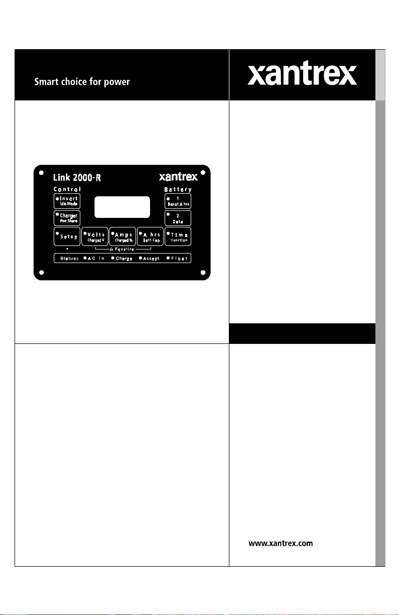
Link 2000-R
i4.40
2
TABLE OF CONTENTS
Front Panel and Status Lights 3
How the LINK 2000-R Charges 4–5
Equalizing Cautions! 6
Special Setup for the LINK 2000-R 7
Required Reading 8
Wiring Instructions 9–15
Standby Regulators 15
Warranty 16
Troubleshooting Flow Chart 18
Wiring Diagram 19
The Helping Hand is used to draw your attention to very important sections of this
manual or to indicate items of special interest. Please read these sections carefully.
INSTALLERS! THIS DOCUMENT IS IMPORTANT FOR
OPERATION. PLEASE LEAVE IT WITH THE OWNER!
The LINK 2000-R is an integrated battery monitor, inverter/charger
controller, and advanced alternator regulator. This manual pertains
only to the installation, wiring, and testing of the alternator regulator
portion of the system. All other features and functions concerning
monitor operation and Freedom Inverter/Charger operation are
described in the LINK 2000 Owner's Manual (Part number 445-0198-
01-01). You
must be familiar with that manual before using the LINK
2000-R.
For use only with externally regulated
12- or 24-volt "P" Field type alternators.
See "Required Reading," page 8.
THIS DOCUMENT APPLIES TO LINK 2000-R SERIAL NUMBER 5000 AND ABOVE.
s
SUPPLEMENT TO THE LINK 2000 OWNER'S MANUAL
Notice of Copyright
Xantrex Link 2000-R Battery Monitor © November 2002 Xantrex International. All rights reserved. Xantrex is a registered
trademark of Xantrex International.
Disclaimer
UNLESS SPECIFICALLY AGREED TO IN WRITING, XANTREX TECHNOLOGY INC. (“XANTREX”)
(a) MAKES NO WARRANTY AS TO THE ACCURACY, SUFFICIENCY OR SUITABILITY OF ANY TECHNICAL OR
OTHER INFORMATION PROVIDED IN ITS MANUALS OR OTHER DOCUMENTATION.
(b) ASSUMES NO RESPONSIBILITY OR LIABILITY FOR LOSS OR DAMAGE, WHETHER DIRECT, INDIRECT,
CONSEQUENTIAL OR INCIDENTAL, WHICH MIGHT ARISE OUT OF THE USE OF SUCH INFORMATION. THE USE
OF ANY SUCH INFORMATION WILL BE ENTIRELY AT THE USER’S RISK.
Date and Revision: November 2002, Revision 1
Part Number: 445-0197-01-01
Contact Information Web: www.xantrex.com Email: CustomerService@xantrex.com
Phone: 1 800 670 0707 (toll free in North America) 1 604 422 2777 (direct) Fax: 1 604 420 2145
3
FRONT PANEL SWITCHES
The operation of the front panel is the same as the LINK 2000 with the exception of the
TIME switch. When the alternator regulator is on (REG ON energized) and TIME is
selected, the alternator output current is displayed. It is preceded with the character "
AA
AA
A".
For example, an alternator output current of 100 amps would be displayed as AI00.
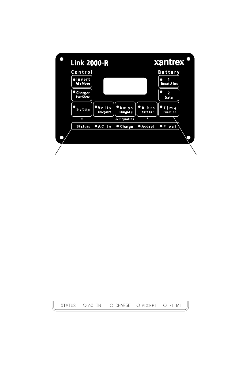
STATUS LIGHTS
The status lights on the front of LINK 2000-R use LEDs (light-emitting diodes) to indicate
which cycle the alternator regulator is in during charging. The meaning of the lights is the
same as described in the LINK 2000 installation manual. The only difference is that when
there is no external AC power available, and
the regulator is turned on, the status lights
indicate the charge cycle for the alternator regulator. If external AC power is available, the
charger is turned
ON, and the alternator is also charging the battery, the status lights indicate
the cycle of both the charger and the alternator regulator.
Selecting TIME when the alternator regulator
is operating displays the alternator output
current. The current is displayed with an "
A"
preceding the value.
Status lights indicate which cycle the regulator
(and/or the charger) is in. The AC light will be
OFF if there is no external AC input.
FRONT PANEL AND STATUS LIGHTS
The front panel operation of the LINK 2000-R is exactly the same as described in the
LINK 2000 owner's manual, with the exceptions noted below.
AC IN: Green LED on when AC is present.
CHARGE: Red LED on when charger/alternator is in bulk CHARGE Cycle.
Flashes Red LED when charger/alternator is in EQUALIZE Cycle.
ACCEPT: Orange LED on when charger/alternator is in ACCEPTANCE Cycle.
FLOAT: Green LED on when charger/alternator is in FLOAT Cycle.
i4.40

4
ACCEPTANCE CYCLE
Behavior: Battery amps falling, voltage at 14.4 V for 12 V systems, 28.8 for
24 V. (Voltage depends on battery type and ambient temperature settings.)
The Acceptance Cycle guarantees thorough charging by continuing to charge
the battery until the charging current becomes a small percentage of battery
capacity (2% default). The alternator output is varied to maintain the battery at
the acceptance voltage. During the Acceptance Cycle the alternator current limit
will not be exceeded even if a heavy load is placed on the system.
When the batteries have reached the acceptance voltage and the current is
below 2%, the Acceptance Hold Cycle begins. If the Acceptance Cycle has lasted
3.5 hours, the Float Cycle begins, even if the charged parameters have not been
met. If the voltage of either battery falls below the acceptance voltage for more
than two minutes, the Charge Cycle starts again.
HOW THE LINK 2000-R CHARGES
See page 18 of LINK 2000 manual for details of the Ideal Charge Curve.
The LINK 2000-R uses the Ideal Regulator Output Module to control the alternator
to conform to the Ideal Charge Curve’s four defining cycles; Charge, Acceptance, Float,
and Equalize. The following discusses details of each of the cycles.
NOTES: 1) Terminal references for the Ideal Regulator Output Module.
2) Voltage values given are for 70 °F and liquid lead-acid batteries.
TURNING THE REGULATOR ON
The regulator is turned on by supplying 12 V or 24 V to the REG ON (brown
wire) terminal.
It must have power only when the engine is running. See page 13.
DELAY START-UP
Behavior: No output on the Field terminal (blue wire).
Two-second delay allows time for the engine to start.
RAMPING UP
Behavior: Output of alternator increases over a 20-second period.
Ramping up the alternator output avoids shock-loading the belts with full
alternator output. The output on the FIELD terminal is increased over a 20-second
period until the alternator current limit (default value 100 A) is reached. The Charge
Cycle now begins. If the acceptance voltage is reached before the current limit,
the Acceptance Cycle begins.
CHARGE CYCLE
Behavior: Alternator current at maximum and battery voltage increasing.
The Charge Cycle ensures fast charging without alternator overload. The
alternator current limit will not be exceeded. The FIELD output is varied to hold
the alternator at its current limit until the acceptance voltage is reached. When the
acceptance voltage has been attained by either battery, the Acceptance Cycle begins.
CYCLE
STATUS
LIGHT
RED
LED ON
ORANGE
LED ON

5
FLOAT CYCLE
Behavior: Battery amps below 2%, voltage constant at 13.5 V (27 V FOR
24 V). (Voltage depends on battery type and ambient temperature setting.)
During the Float Cycle the float voltage is maintained. The alternator will
supply up to its current limit to maintain the float voltage and supply DC loads.
RESTARTING THE CHARGE CYCLE
MANUALLY: The Ramp Up Cycle may be manually restarted by turning off
the REG ON terminal and turning it back on again. This will require you to turn
off the key switch supplying REG ON or shutting off and restarting the engine
if REG ON is supplied by an oil pressure switch.
AUTOMATICALLY: The Charge Cycle is automatically restarted if the
voltage of the battery being charged drops 0.2 V (0.4 V for 24 V) below the float
voltage (0.3 V when charging with the inverter/charger) for more than two minutes.
EQUALIZE CYCLE
Behavior: Battery amps constant at 4%, voltage is rising to a maximum
of 16.0 V when charging with the alternator and 16.3 V when charging with
the inverter/charger. (Limited to acceptance voltage for gelled batteries.)
To start the Equalize Cycle press the SETUP BUTTON for five seconds until
the LED begins to flash. Now press both the VOLTS and the A hrs BUTTON
simultaneously. Hold them both down for five seconds until the red CHARGE
LED begins to flash and the “E” in the display goes out. To terminate the Equalize
Cycle and force the system into the float cycle, repeat the same procedure. The
cycle automatically terminates 3.5 hours after initiation, or when the current drops
to 2% of capacity at 16.0 V. (Equalize terminated in eight hours if using the
inverter/charger.)
The Equalize Cycle is a controlled overcharge to remove lead sulfate that is
not removed during normal charging. Liquid batteries should be equalized about
every 30 days when in deep cycling service.
ACCEPTANCE HOLD CYCLE
Behavior: Voltage at 14.4 V (28.8 V for 24 V), battery amps below 2%.
The Acceptance Hold Cycle ensures that the battery has accepted as much
charge as it can. During the Acceptance Hold Cycle the charged voltage is
maintained and charging current is monitored. Both the charged voltage and the
charged current % must continue to be satisfied for 10 minutes for the Acceptance
Hold Cycle to end. The Acceptance Hold Cycle is also terminated after 20
minutes from its beginning even if the battery current has not stayed below the
charged current for the entire time.
If the voltage of the batteries falls below the charged voltage for more than two
minutes, the Charge Cycle starts again.
GREEN
LED ON
RED
LED
FLASH
ORANGE
LED ON

6
EQUALIZING CAUTIONS!
Turn off sensitive electronics before equalizing.
Equalizing causes the battery to gas. You should check the battery electrolyte
before and after equalization. Do not over-fill before equalization as the electrolyte may
expand and cause it to flow over the tops. You should be present during this type of
charging. Hydrogen and oxygen gas is generated during equalization. Make sure
there is adequate ventilation.
Batteries should not be equalized every charge/discharge cycle. Normally, the
battery is cycled between 50% charged and the 85% to 95% charged level reached by
the normal Charge and Acceptance Cycle. Every 30 days, though, the batteries should
be equalized to regain full capacity and extend life.
To equalize, first go through a complete Charge and Acceptance Cycle. Check the
electrolyte level, but do not overfill. Re-check and top off the electrolyte
after equalizing.
Remember, equalizing is constant current charging with a small regulated
current that permits a higher maximum voltage. The goal is to use a small current
and gradually let the battery rise to its maximum voltage.
EQUALIZING GELLED BATTERIES
Gelled batteries are not normally equalized. However, if the battery has been
severely discharged, the voltage of the battery may easily reach the acceptance level
with a very small current. In fact, the current may be less than the 2% required to termi-
nate the Acceptance Cycle. This can cause the system to believe that the battery is full
and switch to the Float Cycle. Equalization may be the only way to get the battery to
accept a charge. Be sure that the battery TYPE # is set to #1 or #2 before using this
cycle on gelled batteries.
The equalization voltage is limited to the acceptance
voltage but the cycle lasts for 3.5 hours. (Eight hours if using the Freedom charger.)
Please consult your battery manufacturer regarding the appropriateness of this cycle
for their batteries.
 Loading...