

ADDENDUM TO 975-0003-01-03 REV A
SUN TIE XR INSTALLATION & OPERATOR’S MANUAL
COMBINER BOARD VARIATION
DC Wiring
The combiner board (included on some models) in the STXR accepts up to six individual PV array circuits
(positive and negative wires). Each circuit on the combiner board contains a fuse to protect against overcurrent. Always replace this fuse with one of the
same type and rating
(GBB, 20 amp maximum, ceramic type,
0.25" x 1.25").
The combiner board PV array input connection block is located in the lower section of the STXR unit.
STXR 1500 and STXR 2500 DC Wiring
PV Array Conduit/Wire Run
1.1.
1. Install the DC conduit from the PV arrays to the bottom of the STXR unit, via one of the knockout holes.
1.1.
2.2.
2. Route the wires from the PV array(s) through conduit and into the lower section of the STXR enclosure.
2.2.
NOTE: If more than one PV array is used, label the wire pairs (positive and negative)
appropriately (i.e., PV 1, PV 2, etc.).
3.3.
3. Connect the positive (+) wire from the #1 array to the terminal strip labeled PV INPUT 1 POSITIVE
3.3.
terminal. Check that the wire is in the proper location and tighten the screw.
4.4.
4. Connect the negative (–) wires from the PV array to the PV INPUT 1 NEGATIVE terminal. Check that the
4.4.
wire is in the proper location and tighten the screw.
5.5.
5. Repeat this procedure for each PV array circuit, connecting the #2 PV Positive wire to the terminal
5.5.
labeled PV INPUT 2 POSITIVE, etc.
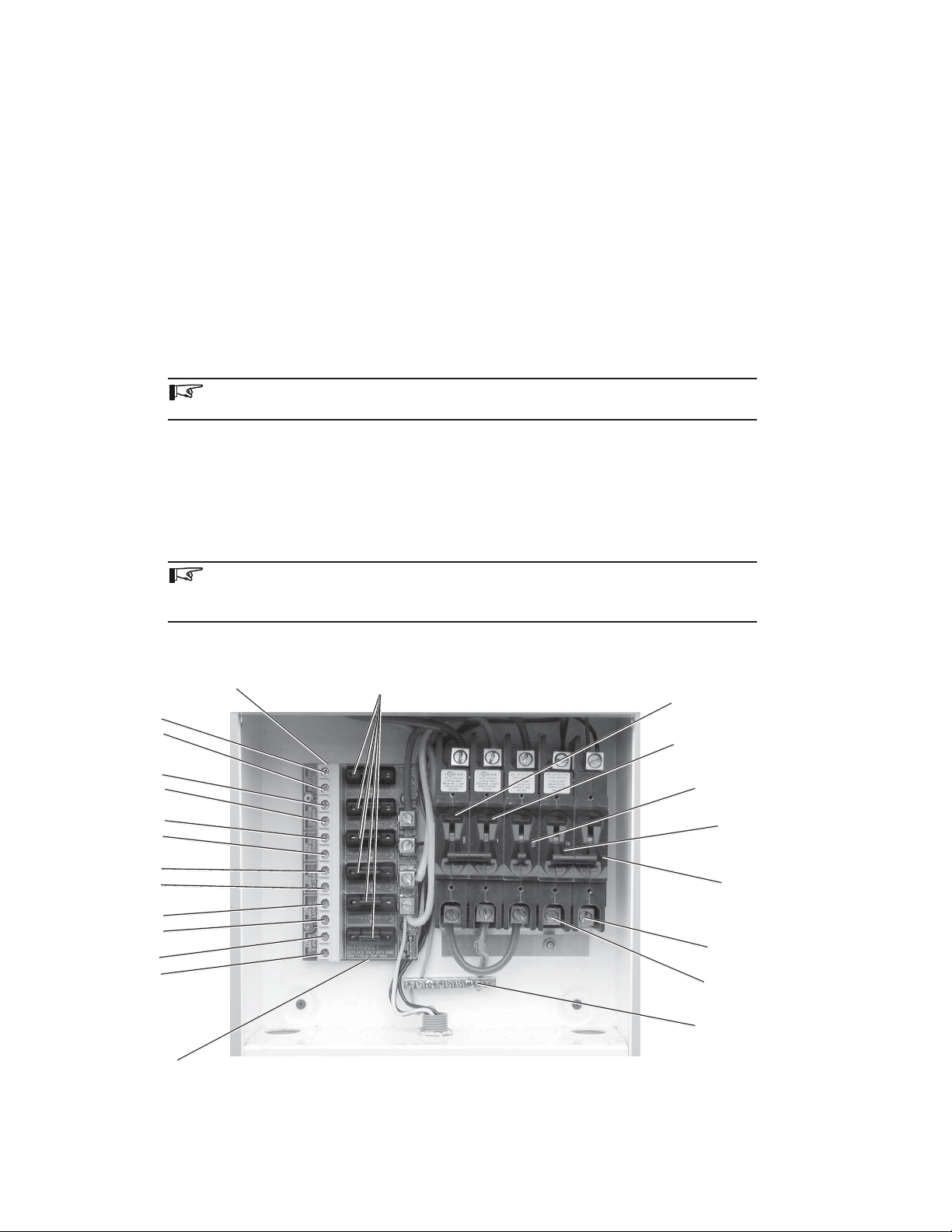
Solar DC terminal block
Solar input 1
+
-
Solar input 2
+
-
Solar input 3
+
-
Solar input 4
+
-
Solar input 5
+
-
Solar input 6
+
-
NOTE: The solar arrays do not have to connect in the order marked on the board (this is
just for reference). All solar array positives on the combiner board are joined together
AFTER the fuse.
Solar DC Fuses
PVGFP (ganged)
100 amp DC breaker
PVGFP (ganged)
1 amp DC breaker
Solar array
100 amp DC breaker
L1
15 amp AC breaker
(ganged)
L2
15 amp AC breaker
(ganged)
L2 breaker
AC connection
L1 breaker
AC connection
Combiner board
STXR1500 and STXR2500 Electrical Component Location
©2002 Xantrex/Trace Engineering
P/N 976-0035-01-01 Rev A 04/2002
Grounding
block
Figure 1
 Loading...