


 ™ GSM
™ GSM
Generator Start Module
Installation and Operation Guide
ã2001 Xantrex Technology Inc. |
P/N 975-0008-01-02 Rev. A 01/01 |
GSM–Generator Start Module |
|
Table of Contents |
|
1.0 INTRODUCTION ................................................................. |
1 |
Unpacking and Inspection ............................................................................. |
1 |
Controls and Indicators ................................................................................. |
2 |
Indicator LEDs ....................................................................................... |
2 |
GENERATOR RUN/GLOWSTOP RELAY 7 LED ......................... |
2 |
GENERATOR START RELAY 8 LED ........................................... |
2 |
INVERTER OPERATIONAL LED ................................................. |
2 |
Switches ................................................................................................ |
3 |
GENERATOR START Switch ....................................................... |
3 |
INVERTER ERROR Switch .......................................................... |
3 |
Internal Components ..................................................................................... |
4 |
Relays .................................................................................................... |
4 |
Relay Terminal Block ............................................................................. |
4 |
Ground Stud .......................................................................................... |
4 |
Fuses ..................................................................................................... |
4 |
2.0 INSTALLATION ................................................................... |
6 |
Tools Required ............................................................................................... |
6 |
Pre-Installation .............................................................................................. |
6 |
Mounting Procedure ...................................................................................... |
6 |
Generator Wiring ........................................................................................... |
9 |
To connect the generator wires to the terminal block ........................... |
9 |
Two-Wire Start Circuits ....................................................................... |
10 |
Wiring Honda-Type Generators .......................................................... |
11 |
Wiring Onan-Type Generators ............................................................ |
12 |
Error Indicator Wiring .................................................................................. |
13 |
Communication Cable ................................................................................. |
14 |
3.0 OPERATION ...................................................................... |
15 |
Operation and Test ...................................................................................... |
15 |
Internal Sticker .................................................................................... |
16 |
Danger Label ....................................................................................... |
16 |
4.0 TROUBLESHOOTING ...................................................... |
17 |
5.0 SERVICE INFORMATION .................................................. |
18 |
6.0 WARRANTY ...................................................................... |
19 |
7.0 SPECIFICATIONS .............................................................. |
20 |
©2001 Xantrex Technology Inc. |
i |
IMPORTANT SAFETY INSTRUCTIONS
This manual contains important safety instructions that should be followed during the installation and maintenance of this product.
To reduce the risk of electrical shock, and to ensure the safe installation and operation of this product, the following safety symbols have been placed throughout this manual to indicate dangerous conditions and important safety instructions.
WARNING - A dangerous voltage or condition exists in this area. Use extreme caution when performing these tasks.
AVERTISSEMENT - Une tension ou condition dangereuse existe dans cette zone. Faire preuve d’extrême prudence lors de la réalisation de ces tâches.
CAUTION - This procedure is critical to the safe installation or operation of the unit. Follow these instructions closely.
ATTENTION - Cette procédure est essentielle à l’installation ou l’utilisation de l’unité en toute sécurité. Suivre ces instructions de près.
NOTE - This statement is important. Follow instructions closely.
NOTE - Cette déclaration est importante. Suivre les instructions de près.
•All electrical work must be done in accordance with local, national, and/or international electrical codes.
•Before installing or using this device, read all instructions and cautionary markings located in the manual and on the generator.
•Do not expose this unit to rain, snow or liquids of any type. This product is designed only for indoor mounting.
•To reduce the chance of short-circuits, use insulated tools when installing or working with this product, the inverter, the batteries or generator.
•Remove all jewelry such as rings, bracelets, necklaces, etc., while installing the GSM. This will greatly reduce the chance of accidental exposure to live circuits.
•The inverter contains more than one live circuit (batteries, PV array, AC line, etc.). Power may be present at more than one source.
•To reduce risk of electric shock, disconnect all wiring before attempting any maintenance or cleaning. Turning off the device may not reduce this risk.
•Disable the generator’s starting circuit by disconnecting the starter battery, spark plug, etc., before wiring this device.
SAVE THESE INSTRUCTIONS
ii |
©2001 Xantrex Technology Inc. |
Disclaimer of Liability
Since the use of this manual and the conditions or methods of installation, operation, use and maintenance of the unit are beyond the control of Xantrex Technology Inc., the company does not assume responsibility and expressly disclaims liability for loss, damage, or expense arising out of or any way connected with such installation, operation, use, or maintenance.
©2001 Xantrex Technology Inc. |
iii |

NOTE: Due to continual improvement through product updates, photographs and/or illustrations used in this manual may not exactly match your unit. Xantrex Technology Inc., reserves the right to update this product without notice or releasing an updated manual when fit, form or function are not affected.
iv |
©2001 Xantrex Technology Inc. |
1.0 INTRODUCTION
The GSM (Generator Start Module) is an accessory for selected Trace™ inverter/charger models allowing automatic generator control and inverter error indication when using the optional SWRC remote control. The unit contains three relays providing normally open (N.O.), normally closed (N.C.) and common (COM) contacts. Relays RY7 and RY8 are used for generator control. Relay RY11 is used to indicate an error condition (via an external indicator) whenever the inverter’s output is shutdown. This could be a bell, buzzer, light, etc.
The unit interfaces the inverter (via a phone type cable) to an auto-start/ stop generator. Commands from the inverter control the generator when defined parameters (programmed via the SWRC or SWCA for PS Series models) are met. Refer to the inverter operator’s manual for setting the various parameters for generator operation.
Front panel LEDs provide a visual display of relay activity whenever a relay contact receives an engage command from the inverter. A highly visible blue LED indicates the inverter is operational.
Unpacking and Inspection
Carefully inspect the contents of the shipping carton for damages. Report any damages to the carrier immediately.
The following items are packed with the GSM:
•Generator Start Module unit (GSM)
•25-foot cable
•Operator’s manual
•Generator Danger Label
Report any missing items to Xantrex Technology Inc., immediately.
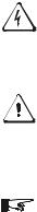
Figure 1
Generator Start Module (GSM)
©2001 Xantrex Technology Inc. |
1 |
1.0 INTRODUCTION
Controls and Indicators
Indicator LEDs
Three LEDs located on the front panel of the GSM indicate the relay control signal status from the inverter.
NOTE: The LEDs are unaffected by the GSM’s switch positions or fuse condition.
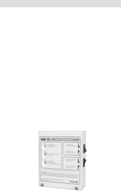
GENERATOR RUN/GLOWSTOP RELAY 7 LED
The yellow LED indicates relay RY7 is receiving a control signal to engage the relay and RUN the generator or provide a GLOWSTOP signal (for diesel generators). The LED turns ON when the relay’s COM and N.O. contacts engage. The function of this relay is dependent on the selection made (using the SWRC) as to whether it is used to RUN the generator or provide GLOWSTOP control.
GENERATOR START RELAY 8 LED
The green LED indicates relay RY8 is receiving a START signal from the inverter. The LED turns ON when the relay’s COM and N.O. contacts engage.
INVERTER OPERATIONAL LED
The blue LED indicates the inverter’s operational status. If the inverter is powered and ready for operation, the blue SYSTEM OPERATIONAL LED turns ON as soon as the phone-type cable is plugged into the inverter. If the blue LED does not turn ON, the inverter is either not powered, is set to the CHG only mode without any utility pass-through, or has no AC output which may be caused by an error condition.
Yellow LED
RUN/GLOWSTOP
RELAY 7
Green LED
GENERATOR START
RELAY 8
Blue LED
INVERTER OPERATIONAL
OFF = INVERTER ERROR
Figure 2
Indicator LEDs
2 |
©2001 Xantrex Technology Inc. |
1.0 INTRODUCTION
Controls and Indicators (continued)
Switches
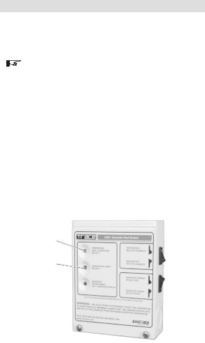
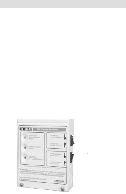
Two switches are provided on the right side of the GSM to effectively disconnect the relay coils from the inverter’s supply voltage (11 VDC), thus preventing the relays from engaging if a control signal is sent out from the inverter. This is a safety feature which allows the generator to be serviced without it unexpectedly starting due to an inverter GEN-START command.
GENERATOR START Switch
The GENERATOR START switch enables the relays by providing the operating voltage to the relay coils RY7 and RY8. When the relays are enabled, they will respond to the control signals provided by the inverter. When the switch is in the RELAYS DISABLED position, the inverter control signals have no effect on relay operation (i.e., the COM and N.C. contacts engage). This switch does not affect the operation of the LEDs which continue to light whenever the inverter sends a CLOSE CONTACT command to the relays.
INVERTER ERROR Switch
The INVERTER ERROR switch provides a simple way to test an externally connected alarm. Once the alarm is tested, this switch should be switched to the RELAY READY position.
GENERATOR
Switch
(RY7 and RY8)
INVERTER ERROR
Switch (RY 11)
Figure 3
Switches
©2001 Xantrex Technology Inc. |
3 |
 Loading...