

Xantrex PowerHub 1800 Installation Guide
975-0289-01-01(PowerHub_1800).book Page 1 Friday, January 5, 2007 12:47 PM
PowerHub 1800
PH1800
Installation Guide

975-0289-01-01(PowerHub_1800).book Page 2 Friday, January 5, 2007 12:47 PM

975-0289-01-01(PowerHub_1800).book Page i Friday, January 5, 2007 12:47 PM
PowerHub 1800
Installation Guide

975-0289-01-01(PowerHub_1800).book Page ii Friday, January 5, 2007 12:47 PM
About Xantrex
Xantrex Technology Inc. is a world-leading supplier of advanced power electronics and controls with
products from 50 watt mobile units to one MW utility-scale systems for wind, solar, batteries, fuel cells,
microturbines, and backup power applications in both grid-connected and stand-alone systems. Xantrex
products include inverters, battery chargers, programmable power supplies, and variable speed drives
that convert, supply, control, clean, and distribute electrical power.
Trademarks
PowerHub 1800 is a trademark of Xantrex International. Xantrex is a registered trademark of Xantrex
International.
Other trademarks, registered trademarks, and product names are the property of their respective owners
and are used herein for identification purposes only.
Notice of Copyright
PowerHub 1800 Installation Guide © January 2007 Xantrex Internation a l. All rights reserved.
Exclusion for Documentation
UNLESS SPECIFICALLY AGREED TO IN WRITING, XANTREX TECHNOLOGY INC. (“XANTREX”)
(
A) MAKES NO WARRANTY AS TO THE ACCURACY, SUFFICIENCY OR SUITABILITY OF ANY TECHNICAL OR
OTHER INFORMATION PROVIDED IN ITS MANUALS OR OTHER DOCUMENTATION.
(
B) ASSUMES NO RESPONSIBILITY OR LIABILITY FOR LOSSES, DAMAGES, COSTS OR EXPENSES, WHETHER
SPECIAL, DIRECT, INDIRECT, CONSEQUENTIAL OR INCIDENTAL, WHICH MIGHT ARISE OUT OF THE USE OF
SUCH INFORMATION. THE USE OF ANY SUCH INFORMATION WILL BE ENTIRELY AT THE USER’S RISK; AND
(C) REMINDS YOU THAT IF THIS MANUAL IS IN ANY LANGUAGE OTHER THAN ENGLISH, ALTHOUGH
STEPS HAVE BEEN TAKEN TO MAINTAIN THE ACCURACY OF THE TRANSLATION, THE ACCURACY CANNOT
BE GUARANTEED. APPROVED XANTREX CONTENT IS CONTAINED WITH THE ENGLISH LANGUAGE
VERSION WHICH IS POSTED AT WWW.XANTREX.COM.
Date and Revision
January 2007 Revision C
Part Number
975-0289-01-01
Product Number
PH1800-GFP
Contact Information
Telephone: 1 800 670 0707 (toll free North America)
1 360 925 5097 (direct)
Fax: 1 800 994 7828 (toll free North America)
1 360 925 5143 (direct)
Email: customerservice@xantrex.com
Web: www.xantrex.com

975-0289-01-01(PowerHub_1800).book Page iii Friday, January 5, 2007 12:47 PM
About This Guide
Purpose
The purpose of this Installation Guide is to provide procedures for
installing the PowerHub 1800.
Scope
The Guide provides safety guidelines, detailed planning and setup
information, and procedures for installing the inverter. It does not provide
operational or troubleshooting information. It does not provide details
about particular brands of batteries. Consult individual battery
manufacturers for this information.
Audience
Organization
The PowerHub 1800 is an entry-level inverter system. This Guide is
intended for anyone who needs to plan for and install the PowerHub
1800. Permanent installations should be done by certified technicians or
electricians. Installers should have adequate knowledge of national and
local electric code to ensure code-compliance by inspection from the local
electric authority.
This Guide is organized into three chapters and one app e ndix.
Chapter 1 describes the features and functions of the PowerHub 1800.
Chapter 2 contains information on planning the installation of this
equipment.
Chapter 3 contains information on assembling and installing this
equipment.
Appendix A provides electrical and physical specifications for the
PowerHub 1800.
iii
975-0289-01-01(PowerHub_1800).book Page iv Friday, January 5, 2007 12:47 PM
About This Guide
Conventions Used
The following conventions are used in this guide.
WARNING
Warnings identify conditions or practices that could result in personal injury or
loss of life
CAUTION
Cautions identify conditions or practices that could result in damage to the unit or
other equipment.
Important:
but not as serious as a caution or warning.
These notes describe things which are important for you to know,
Abbreviations and Acronyms
Abbreviation or Acronym Definition
AAmps
AC Alternating Current
DC Direct Current
ft-lbs Foot-pounds (a measure of torque)
kW Kilowatts (1000 watts)
LED Light Emitting Diode
Nm Newton-meters (a measurement of torque)
PV Photovoltaic
RE Renewable Energy
Vac Volts AC
Vdc Volts DC
WWatts
Related Information
You can find more information about this product by seeing the
PowerHub 1800 Operator’s Guide (part nu mber 9 75-02 88-01- 01 Rev A).
You can find more information about Xantrex Technology Inc. as well as
its products and services at www.xantrex.com.
A French version of this document is available at www.xantrex.com.
iv 975-0289-01-01
975-0289-01-01(PowerHub_1800).book Page v Friday, January 5, 2007 12:47 PM
Important Safety Instructions
WARNING
This chapter contains important safety and operating instructions. Read and keep
this Installation Guide for future reference.
WARNING: Limitations on use
The PowerHub 1800 is not intended for use in connection with life support
systems or other medical equipment or devices.
WARNING
To avoid the risk of carbon mo noxide poisoning, generators are not to be used
indoors. When generators are used outdoors there must be sufficient circulation
to vent the carbon monoxide.
1. Before installing and using the PowerHub, read all instructions and
cautionary markings on the PowerHub, the batteries, and in both this
Installation Guide and the Operator’s Guide.
2. The PowerHub is intended for indoor use only. Do not expose the
PowerHub to rain, snow, or spray. To reduce risk of fire hazard, do
not cover or obstruct the ventilation openings. Do not install the
PowerHub in a zero-clearance compartment. Overheating may result.
3. The PowerHub may connect to as many as three source s of DC Power
and one source of AC Power. To reduce the risk of electrical shock,
disconnect all sources of AC and DC power from the PowerHub
before attempting any maintenance or cleaning or working on any
circuits connected to the PowerHub. Turning off controls will not
eliminate this risk.
4. Use only attachments that are intended for use with this product.
Doing otherwise may result in a risk of fire, electric shock, or injury
to persons.
5. To avoid a risk of fire and electric shock, make sure that all of the
installation wiring is in good condition and that wire is not
undersized. Do not operate the PowerHub with damaged or
substandard wiring.
6. Do not operate the PowerHub if it has received a sharp blow, been
dropped, or otherwise damaged in any way. If the PowerHub is
damaged, see the Warranty section.
v
975-0289-01-01(PowerHub_1800).book Page vi Friday, January 5, 2007 12:47 PM
Safety
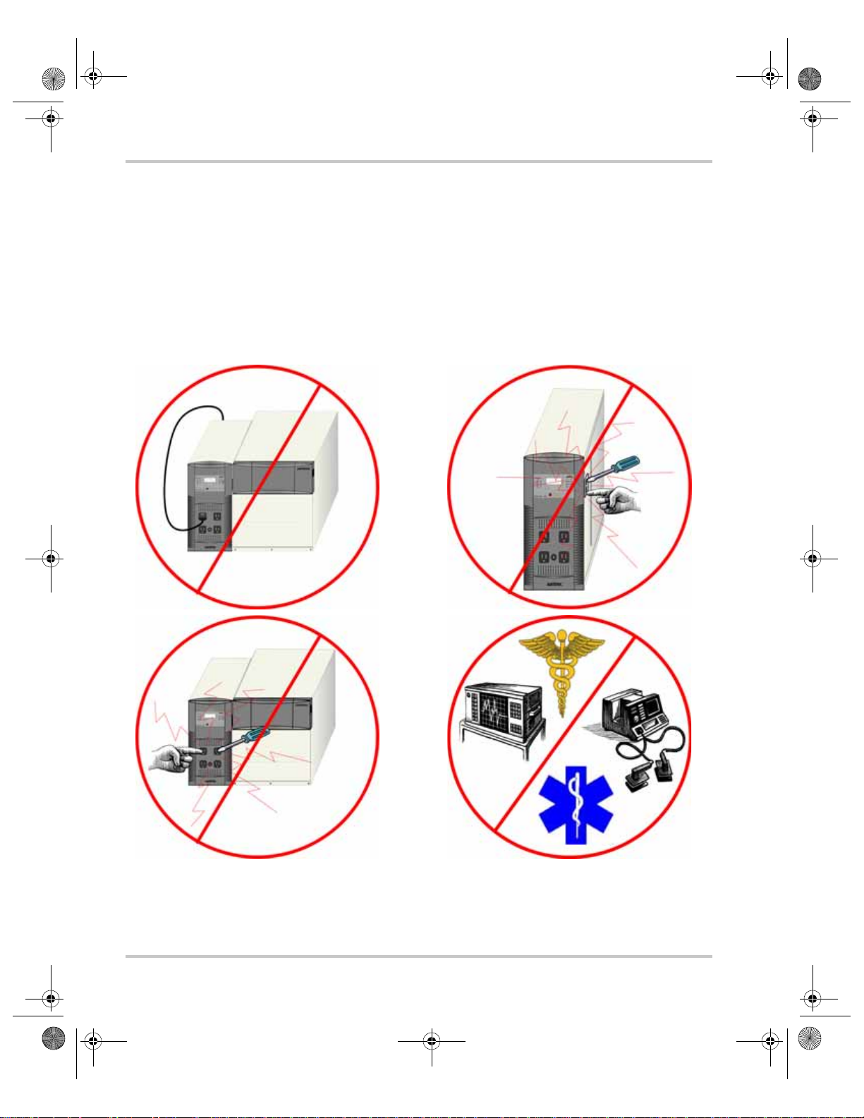
7. Do not disassemble the PowerHub, except where noted to wire it for a
permanent installation. The PowerHub 1800 contains no userserviceable parts. See Warranty for instructions on obtaining service.
Attempting to service the PowerHub yourself may result in a risk of
electrical shock or fire and will void your warranty. Internal
capacitors remain charged after all power is disconnected.
8. The PowerHub must be provided with an equipment-grounding
conductor. Grounding and all other wiring must comply with National
and local codes and regulations.
No!
No!
No!
No!
Figure i
vi 975-0289-01-01
Basic Safety

975-0289-01-01(PowerHub_1800).book Page vii Friday, January 5, 2007 12:47 PM
Precautions When Working With Batteries
WARNING: Fire or Explosion Hazard
1. Use only SEALED batteries with the PowerHub 1800.
2. Follow all instructions published by the battery manufacturer.
3. Working in the vicinity of batteries may be dangerous. Unsealed
batteries can generate explosive gases during normal operation.
Therefore, you must read this guide and follow the instructions
exactly before installing or using the PowerHub.
4. This equipment contains components which tend to produce arcs or
sparks. To prevent fire or explosion, do not install the PowerHub in
locations that require ignition-protected equipment. This includes any
space containing gasoline-powered machinery, fuel tanks, as well as
joints, fittings, or other connections between components of the fuel
system.
5. To reduce the risk of battery explosion, follow these instructions and
those published by the battery manufacturer.
6. Make sure that nothing is blocking the air vents on the back of the
enclosure.
7. Never smoke or allow a spark or flame near the batteries.
Safety
8. Use caution to reduce the risk of dropping a metal tool on the
batteries. It could spark or short circuit the battery or other electrical
parts and could cause an explosion.
9. Remove all personal metal items, like rings, bracelets, and watches
when working with batteries. Batteries can produce a short circuit
current high enough to weld metal, causing a severe burn.
10. Have someone within range of your voice or close enough to come to
your aid when you work near a battery.
11. Wear complete eye protection and clothing protection. Avoid
touching your eyes while working near batteries.
12. Have plenty of fresh water and soap nearby in case battery acid
contacts skin, clothing, or eyes.
975-0289-01-01 vii
975-0289-01-01(PowerHub_1800).book Page viii Friday, January 5, 2007 12:47 PM
Safety
13. If battery acid contacts skin or clothing, wash immediately with soap
and water. If acid enters your eye, immediately flood it with running
cold water for at least twenty minutes and get medical attention
immediately.
Precautions for Using Rechargeable Appliances
CAUTION: Equipment Damage
This equipment produces a modified sine wave output. Equipment damage may
occur if the rechargeable appliance is not designed to use modified sine wave
output. If you are unsure about using your rechargeable appliance with the
modified sine wave, contact the equipment manufacturer.
Most rechargeable battery-operated equipment uses a separate charger or
transformer that is plugged into an AC receptacle and produces a low
voltage charging output.
Some chargers for small rechargeable batteries can be damaged if
connected to the PowerHub. Do not use the following with the PowerHub:
• Small battery-operated appliances like flashlights, razors, and night
lights that can be plugged directly into an AC receptacle to recharge.
• Some chargers for battery packs used in power hand tools. These
affected chargers display a warning label stating that dangerous
voltages are present at the battery terminals.
FCC/ICES 003 Information to the User
This equipment has been tested and found to comply with the limits for a
Class B digital device, pursuant to part 15 of the FCC Rules. These limits
are designed to provide reasonable protection against harmful interference
in a residential installation.
This equipment generates, uses and can radiate radio frequency energy
and, if not installed and used in accordance with the instructions, may
cause harmful interference to radio communications. However, there is no
guarantee that interference will not occur in a particular installation. If this
equipment does cause harmful interference to radio or television reception,
which can be determined by turning the equipment off and on, the user is
encouraged to try to correct the interference by one or more of the
following measures:
viii 975-0289-01-01
975-0289-01-01(PowerHub_1800).book Page ix Friday, January 5, 2007 12:47 PM
• Reorient or relocate the receiving antenna.
• Increase the separation between the equipment receiver.
• Connect the equipment into an outlet on a circuit different from that
to which the receiver is connected.
• Consult the dealer or an experienced radio/TV technician for help.
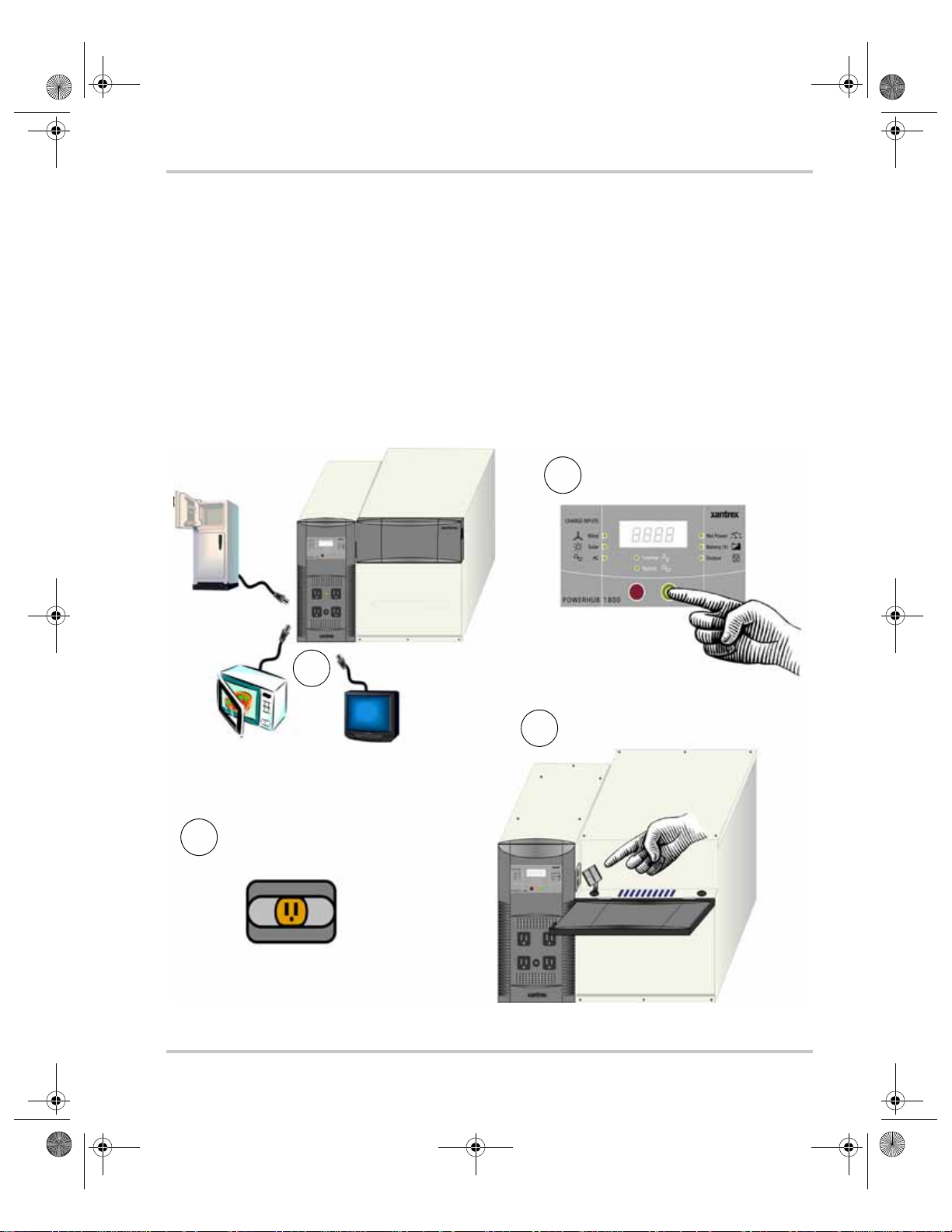
Power Down Procedure
If softwired...... To Power Down the PowerHub 1800:
Press ON/OFF Switch to turn
2
OFF Inverter/Charger
Safety
1
Disconnect the PowerHub
3
from the generator and
turn the generator OFF.
OFF
Figure ii
975-0289-01-01 ix
Power Down Procedure for Softwired Installations
Disconnect Loads
Disconnect the Battery Box(es)
4
from the Inverter
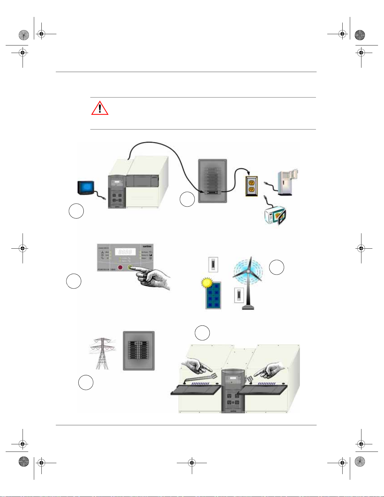
975-0289-01-01(PowerHub_1800).book Page x Friday, January 5, 2007 12:47 PM
Safety
If hardwired...... To Power Down the PowerHub 1800:
WARNING: Shock Hazard
If no DC disconnect is used, then the DC input sources (solar or wind) will have
to be physically disconnected to ensure power is OFF.
2
1
Disconnect any loads directly
connected to the front panel of
the PowerHub
Press ON/OFF
3
Switch to turn OFF
Inverter/Charger
Disconnect the Utility
5
power by opening the AC
input circuit breaker in the
main panel.
Disconnect Loads connected to
the PowerHub through AC
Distribution Panel (Sub-panel)
by opening the Inverter Output
Circuit Breaker.
Disconnect the
DC Input.(s)
Disconnect the Battery Box(es)
6
from the Inverter
4
Figure iii
Power Down Procedure for Hardwired Installations
x 975-0289-01-01

975-0289-01-01(PowerHub_1800).book Page xi Friday, January 5, 2007 12:47 PM
Contents
Important Safety Instructions
Precautions When Working With Batteries - - - - - - - - - - - - - - - - - - - - - - - - - - - - -vii
Precautions for Using Rechargeable Appliances - - - - - - - - - - - - - - - - - - - - - - - - - viii
FCC/ICES 003 Information to the User - - - - - - - - - - - - - - - - - - - - - - - - - - - - - - - viii
Power Down Procedure - - - - - - - - - - - - - - - - - - - - - - - - - - - - - - - - - - - - - - - - - - ix
- - - - - - - - - - - - - - - - - - - - - - - - - - - - - - - - - - -v
1 Introduction
Features and Functions - - - - - - - - - - - - - - - - - - - - - - - - - - - - - - - - - - - - - - - - - - 1–2
Applications - - - - - - - - - - - - - - - - - - - - - - - - - - - - - - - - - - - - - - - - - - - - - - - - - 1–5
Softwired Generator Applications (Plug-and-go) - - - - - - - - - - - - - - - - - - - - - - 1–5
Hardwired Permanent Applications - - - - - - - - - - - - - - - - - - - - - - - - - - - - - - - 1–6
Utility Backup Applications - - - - - - - - - - - - - - - - - - - - - - - - - - - - - - - - - 1–6
Solar Applications - - - - - - - - - - - - - - - - - - - - - - - - - - - - - - - - - - - - - - - 1–7
Wind Applications - - - - - - - - - - - - - - - - - - - - - - - - - - - - - - - - - - - - - - - 1–8
Combination Applications - - - - - - - - - - - - - - - - - - - - - - - - - - - - - - - - - - 1–9
2 Planning
Planning Overview - - - - - - - - - - - - - - - - - - - - - - - - - - - - - - - - - - - - - - - - - - - - -2–2
Tools Required- - - - - - - - - - - - - - - - - - - - - - - - - - - - - - - - - - - - - - - - - - - - - - - -2–3
Hardware / Materials Required - - - - - - - - - - - - - - - - - - - - - - - - - - - - - - - - - - - - -2–3
Environmental Requirements - - - - - - - - - - - - - - - - - - - - - - - - - - - - - - - - - - - - - -2–3
Dimensions - - - - - - - - - - - - - - - - - - - - - - - - - - - - - - - - - - - - - - - - - - - - - - - - - -2–4
Batteries - - - - - - - - - - - - - - - - - - - - - - - - - - - - - - - - - - - - - - - - - - - - - - - - - - - - 2–5
Renewable Energy (RE) - - - - - - - - - - - - - - - - - - - - - - - - - - - - - - - - - - - - - - - - - 2–8
Solar Panels - - - - - - - - - - - - - - - - - - - - - - - - - - - - - - - - - - - - - - - - - - - - - - 2–8
Wind - - - - - - - - - - - - - - - - - - - - - - - - - - - - - - - - - - - - - - - - - - - - - - - - - - - 2–8
3 Installation
Installation Overview - - - - - - - - - - - - - - - - - - - - - - - - - - - - - - - - - - - - - - - - - - - 3–1
Assembling the Components - - - - - - - - - - - - - - - - - - - - - - - - - - - - - - - - - - - - - -3–2
Preparing the Battery Bank - - - - - - - - - - - - - - - - - - - - - - - - - - - - - - - - - - - - 3–4
Connecting the Battery Bank to the Inverter - - - - - - - - - - - - - - - - - - - - - - - - - 3–6
Connecting Two Battery Boxes to the Inverter - - - - - - - - - - - - - - - - - - - - - - -3–7
Replacing the Top to the Battery Box - - - - - - - - - - - - - - - - - - - - - - - - - - - - - 3–8
975-0289-01-01 xi

975-0289-01-01(PowerHub_1800).book Page xii Friday, January 5, 2007 12:47 PM
Contents
Wiring - - - - - - - - - - - - - - - - - - - - - - - - - - - - - - - - - - - - - - - - - - - - - - - - - - - - - 3–9
Plug-and-go (Softwiring) - - - - - - - - - - - - - - - - - - - - - - - - - - - - - - - - - - - - - 3–9
Permanent Wiring (Hardwiring) - - - - - - - - - - - - - - - - - - - - - - - - - - - - - - - - 3–10
Terminal Access - - - - - - - - - - - - - - - - - - - - - - - - - - - - - - - - - - - - - - - 3–10
Removing the Factory-installed AC Cord and Knockouts - - - - - - - - - - - - 3–11
AC Input and Output Wiring from a Generator - - - - - - - - - - - - - - - - - - - 3–13
AC Input and Output Wiring from the Utility Grid - - - - - - - - - - - - - - - - 3–14
DC Wiring with Ground Fault Protection
(Renewable Energy Solar Panel; Maximum 400 W) - - - - - - - - - - - - - - - 3–15
DC Wiring with Ground Fault Protection
(Renewable Energy Solar Array; Maximum 1000 W) - - - - - - - - - - - - - - 3–16
DC Wiring (Renewable Energy Wind, Maximum 1000 W) - - - - - - - - - - - 3–17
Replacing the Top Cover - - - - - - - - - - - - - - - - - - - - - - - - - - - - - - - - - - 3–18
Double-check - - - - - - - - - - - - - - - - - - - - - - - - - - - - - - - - - - - - - - - - - - - - - - - 3–18
Power Up Procedure- - - - - - - - - - - - - - - - - - - - - - - - - - - - - - - - - - - - - - - - - - - 3–19
Power Down Procedure- - - - - - - - - - - - - - - - - - - - - - - - - - - - - - - - - - - - - - - - - 3–21
Ground Fault Protection - - - - - - - - - - - - - - - - - - - - - - - - - - - - - - - - - - - - - - - - 3–23
Replacing the Ground Fault Protection Fuse - - - - - - - - - - - - - - - - - - - - - - - - 3–23
A Specifications
Electrical Specifications - - - - - - - - - - - - - - - - - - - - - - - - - - - - - - - - - - - - - - - - -A–2
Physical Specifications - - - - - - - - - - - - - - - - - - - - - - - - - - - - - - - - - - - - - - - - - -A–3
Battery Charger Specifications - - - - - - - - - - - - - - - - - - - - - - - - - - - - - - - - - - - - -A–3
Charging Profiles - - - - - - - - - - - - - - - - - - - - - - - - - - - - - - - - - - - - - - - - - - -A–5
40-amp Charging Profile - - - - - - - - - - - - - - - - - - - - - - - - - - - - - - - - - - -A–5
10-amp Charging Profile - - - - - - - - - - - - - - - - - - - - - - - - - - - - - - - - - - -A–6
0-amp Charging Profile - - - - - - - - - - - - - - - - - - - - - - - - - - - - - - - - - - - -A–6
xii 975-0289-01-01

975-0289-01-01(PowerHub_1800).book Page xiii Friday, January 5, 2007 12:47 PM
Figures
Figure i Basic Safety - - - - - - - - - - - - - - - - - - - - - - - - - - - - - - - - - - - - - - - - - - - - vi
Figure ii Power Down Procedure for Softwired Installations- - - - - - - - - - - - - - - - - - ix
Figure iii Power Down Procedure for Hardwired Installations - - - - - - - - - - - - - - - - - -x
Figure 1-1 The PowerHub 1800 - - - - - - - - - - - - - - - - - - - - - - - - - - - - - - - - - - - - 1–1
Figure 1-2 PowerHub 1800 Components - - - - - - - - - - - - - - - - - - - - - - - - - - - - - - 1–2
Figure 1-3 PowerHub 1800 Features - - - - - - - - - - - - - - - - - - - - - - - - - - - - - - - - - 1–3
Figure 1-4 Softwired Utility or Generator Applications- - - - - - - - - - - - - - - - - - - - - 1–5
Figure 1-5 Hardwired Utility Applications - - - - - - - - - - - - - - - - - - - - - - - - - - - - - 1–6
Figure 1-6 Hardwired Solar Applications - - - - - - - - - - - - - - - - - - - - - - - - - - - - - - 1–7
Figure 1-7 Hardwired Wind Applications- - - - - - - - - - - - - - - - - - - - - - - - - - - - - - 1–8
Figure 1-8 Hardwired Combination Applications- - - - - - - - - - - - - - - - - - - - - - - - - 1–9
Figure 2-1 Dimensions (not to scale) - - - - - - - - - - - - - - - - - - - - - - - - - - - - - - - - - 2–4
Figure 2-2 Battery Box and Battery Size - - - - - - - - - - - - - - - - - - - - - - - - - - - - - - 2–5
Figure 3-1 Preparing the Components for Assembly- - - - - - - - - - - - - - - - - - - - - - - 3–2
Figure 3-2 Connecting the Battery Box to the Inverter - - - - - - - - - - - - - - - - - - - - - 3–3
Figure 3-3 Preparing the Battery Bank- - - - - - - - - - - - - - - - - - - - - - - - - - - - - - - - 3–4
Figure 3-4 Battery Cabling for Two Batteries - - - - - - - - - - - - - - - - - - - - - - - - - - - 3–5
Figure 3-5 Connecting the Battery Bank to the Inverter - - - - - - - - - - - - - - - - - - - - 3–6
Figure 3-6 Connecting Two Battery Boxes to the Inverter- - - - - - - - - - - - - - - - - - - 3–7
Figure 3-7 Replacing the Top to the Battery Box- - - - - - - - - - - - - - - - - - - - - - - - - 3–8
Figure 3-8 Plug-n-Go Wiring (Softwired)- - - - - - - - - - - - - - - - - - - - - - - - - - - - - - 3–9
Figure 3-9 Terminal Access for Hardwiring - - - - - - - - - - - - - - - - - - - - - - - - - - - - 3–10
Figure 3-10 Removing the AC Cord - - - - - - - - - - - - - - - - - - - - - - - - - - - - - - - - - - 3–11
Figure 3-11 Preparing the Knockouts - - - - - - - - - - - - - - - - - - - - - - - - - - - - - - - - - 3–12
Figure 3-12 Connecting the AC Input and Output from a Generator - - - - - - - - - - - - - 3–13
Figure 3-13 Connecting the AC Input and Output from the Utility - - - - - - - - - - - - - - 3–14
Figure 3-14 Connecting the DC Input (Renewable Energy Solar Panel) - - - - - - - - - - 3–15
Figure 3-15 Connecting the DC Input (Renewable Energy Solar Array) - - - - - - - - - - 3–16
Figure 3-16 Connecting the DC Input (Renewable Energy Wind) - - - - - - - - - - - - - - 3–17
Figure 3-17 Replacing the Top Cover on the Inverter- - - - - - - - - - - - - - - - - - - - - - - 3–18
Figure 3-18 Power Up Procedure for Softwired Installations- - - - - - - - - - - - - - - - - - 3–19
Figure 3-19 Power Up Procedure for Hardwired Installations - - - - - - - - - - - - - - - - - 3–20
975-0289-01-01 xiii

975-0289-01-01(PowerHub_1800).book Page xiv Friday, January 5, 2007 12:47 PM
Figures
Figure 3-20 Power Down Procedure for Softwired Installations- - - - - - - - - - - - - - - - 3–21
Figure 3-21 Power Down Procedure for Hardwired Installations - - - - - - - - - - - - - - - 3–22
Figure 3-22 Replacing Ground Fault Protection Fuse- - - - - - - - - - - - - - - - - - - - - - - 3–24
Figure A-1 Three-Stage Charging Process - - - - - - - - - - - - - - - - - - - - - - - - - - - - - A–4
xiv 975-0289-01-01

975-0289-01-01(PowerHub_1800).book Page i Friday, January 5, 2007 12:47 PM
Tables
Table 2-1 Typical AC Appliances and Run Times - - - - - - - - - - - - - - - - - - - - - - - 2–7
Table 3-1 Recommended Wire Gauges for Input and Output Terminals- - - - - - - - - 3–11
Table A-1 Electrical Specifications for the Inverter - - - - - - - - - - - - - - - - - - - - - - - A–2
Table A-2 Electrical Specifications for the Battery Box - - - - - - - - - - - - - - - - - - - - A–2
Table A-3 Physical Specifications of the Inverter - - - - - - - - - - - - - - - - - - - - - - - - A–3
Table A-4 Physical Specifications of the Battery Box - - - - - - - - - - - - - - - - - - - - - A–3
Table A-5 40-amp Charging Profile - - - - - - - - - - - - - - - - - - - - - - - - - - - - - - - - - A–5
Table A-6 10-amp Charging Profile - - - - - - - - - - - - - - - - - - - - - - - - - - - - - - - - - A–6
975-0289-01-01 i

975-0289-01-01(PowerHub_1800).book Page ii Friday, January 5, 2007 12:47 PM
ii
975-0289-01-01(PowerHub_1800).book Page 1 Friday, January 5, 2007 12:47 PM
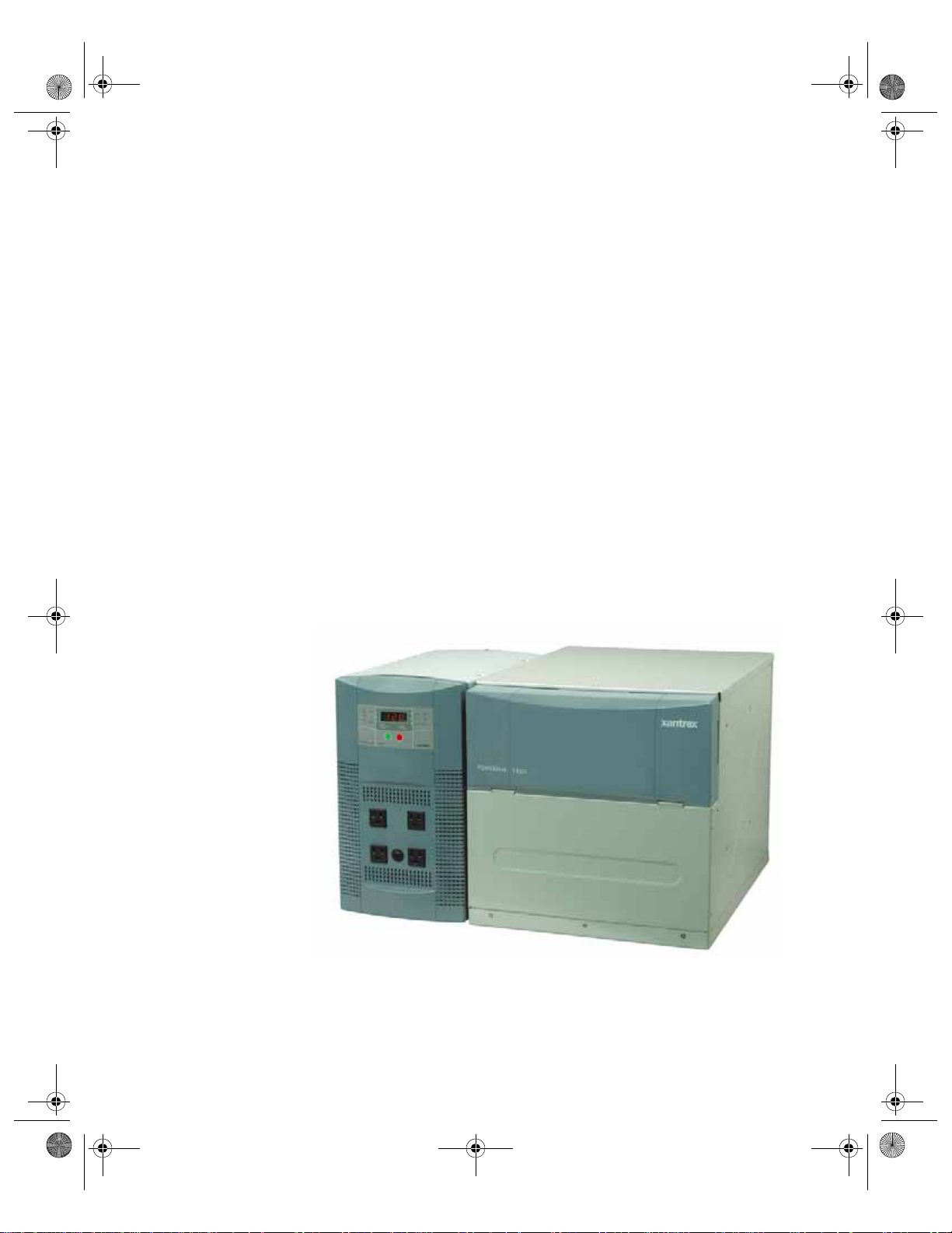
1 Introduction
Chapter 1 describes the features and functions of the PowerHub
1800.
Figure 1-1
The PowerHub 1800
975-0289-01-01(PowerHub_1800).book Page 2 Friday, January 5, 2007 12:47 PM
Introduction
Features and Functions
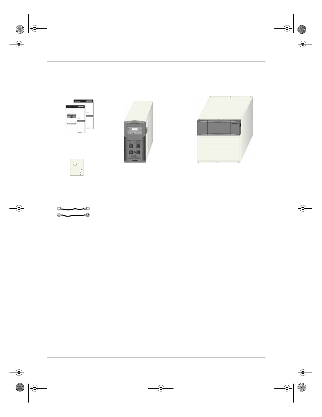
Components The PowerHub 1800 consists of the following components.
Batteries not
included.
PowerHub 1800
Installation Guide
and User’s Guide
Accessory Plate
for Hardwired
Installations
1 set #1/0 AWG
Battery Cables
Figure 1-2
1800 W Inverter/Charger
Includes:
• 1800 W modified sine wave
inverter
• 40 A charger
• Seven 20-amp/32 Vdc
Regulatory approved
automotive-type fuses for
circuitry protection
• One supplementary protector
PowerHub 1800 Components
Includes:
• Battery Cables(positive-red,
• CSA/UL Approved Anderson
• 10 Regulatory approved
Battery Box
negative-black)
( #1/0 AWG 11" long)
connector inside the front panel
for connecting enclosure to
inverter.
20 A/32 Vdc automotive-type
fuses for circuitry protection.
Purpose The PowerHub 1800 is intended to be an entry-level inverter system for
use in support of AC loads up to1440 W continuous, (1800 W on a
5-minute surge). It can be used as a stand-alone power source (softwired)
or be permanently installed on site (hardwired). It is not intended to be
used as an uninterruptible power source (UPS).
Function The PowerHub 1800 is specifically designed to use power stored in two
battery boxes that hold up to four 12 Vdc sealed, lead-acid batteries (not
provided) to power AC loads and to recharge those batteries when an A C
source (generator or utility grid) is available. Run-time on batteries will
vary depending on the size of the loads using the po wer.
1–2 975-0289-01-01
975-0289-01-01(PowerHub_1800).book Page 3 Friday, January 5, 2007 12:47 PM
Features and Functions
Renewable
Energy Input
Inverter
Features
It can also use renewable energy, such as 12 V solar panels and small
12 V wind turbines, to recharge the batteries. Using renewable energy
sources require a permanent “hardwired” installation and will require
additional equipment and structural enhancement to be code-compliant.
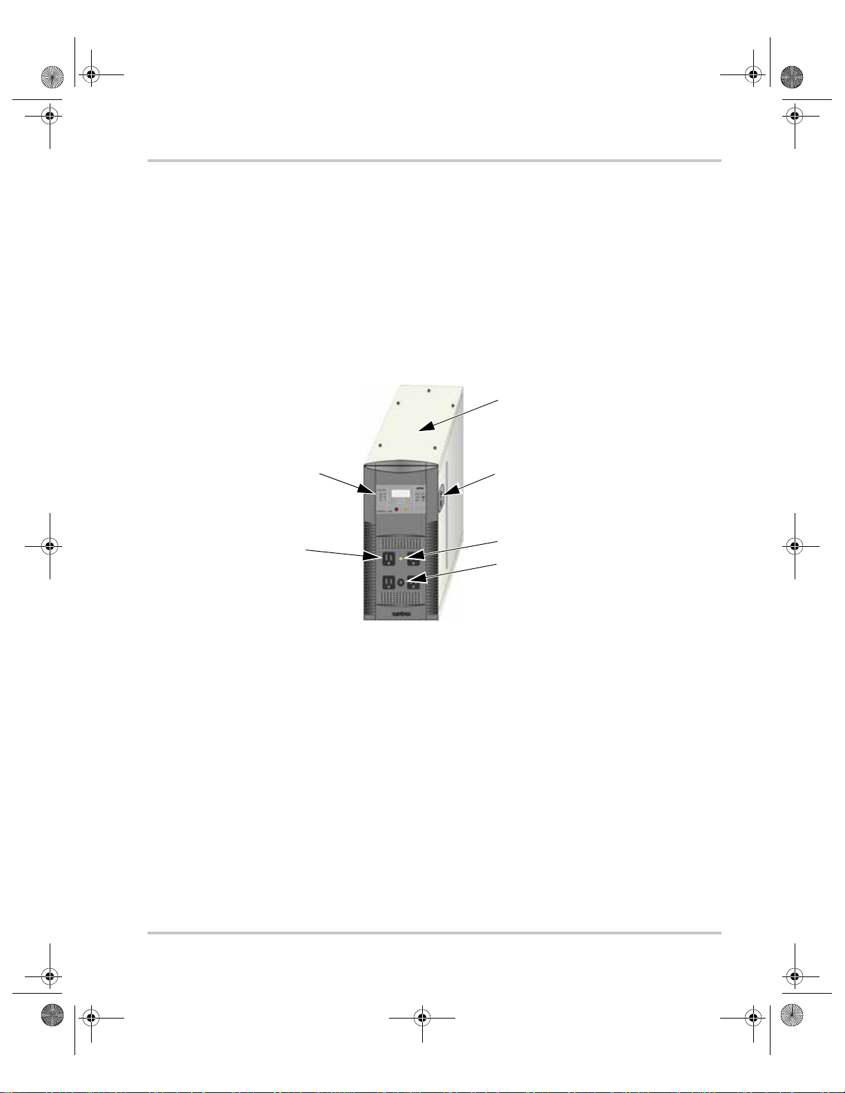
The inverter consists of the following user features:
• Inverter Control Panel
• Four 120 Vac outlets on the front panel.
• One supplementary protector to protect the 120 Vac outlets from
overload.
• Two Battery Box Connection Ports (one on each side)
Inverter
Control
Panel
AC Outlets (x4)
Input/Output terminals are located
under top panel. See Figure 3-9
on page 3–10 for a detailed
illustration of these terminals.
Battery Box Connection Ports
for Anderson-type Connector
Plus (x2-one on each side)
AC Indicator LED
Supplementary
Protector
Figure 1-3
Input/Output
Terminals
PowerHub 1800 Features
The inverter has the following input/output terminals:
• Two DC Anderson ports for 12 V battery connections from the
Battery Box; one on each side.
• Two pairs of DC input terminals for renewable energy connections:
one 32 A input terminal and one 80 A input terminal. External inputs
to these terminals must be externally regulated. Solar panels must
use charge controllers and wind turbines must be self-regulated.
• The 32 A terminals can be used for 12 Vdc input up to
400 W maximum.
• The 80 A terminals can be used for 12 Vdc input up to
1000 W maximum.
• AC input terminal (for grid or generator input)
• AC output terminal (for AC output in hardwired installations)
975-0289-01-01 1–3

975-0289-01-01(PowerHub_1800).book Page 4 Friday, January 5, 2007 12:47 PM
Introduction
Grounding The inverter has two AC Ground terminals and one equipment ground
terminal. In addition, there are ground fault protection terminals for solar
and wind renewable energy inputs (a 32 A and an 80 A). See Figure 3-9
on page 3–10 for a detailed illustration of the Input/Output and ground
terminals.
Regulatory This system complies with CSA 107.1-01 and UL1741and is certified for
a permanent installation that is compliant with national electrical codes.
1–4 975-0289-01-01
 Loading...