


PV 20208
OPERATION and MAINTENANCE
MANUAL
for
MODEL PV-20208
20 KW Grid-Tied
Photovoltaic Inverter
Document #151119
Revision B November 10, 2000
IMPORTANT SAFETY INSTRUCTIONS
SAVE THESE INSTRUCTIONS - THIS MANUAL CONTAINS IMPORTANT INSTRUC-
TIONS FOR TRACE TECHNOLOGIES MODEL PV-20208 GRID TIED PHOTOVOLTAIC
INVERTER THAT SHALL BE FOLLOWED DURING INSTALLATION AND MAINTENANCE
OF THE PV-20208.
Xantrex Technologies Inc./Trace Technologies Corp.
161-G SOUTH VASCO ROAD
Livermore, CA 94550
(925) 245-5400
Copyright 2000, Xantrex T echnologies Inc./T race Technologies Corp.

T able of Contents
Section 1: Product Description
Introduction
Major Components
Interconnection Standards Compliance
Specifications
Equipment Symbol
Section 2: Safety
Safety Features
Isolation Procedure
Anti Island Protection
Section 3: Installation And Initial Turn-On
Isolation Transformer Requirements
T orque and Wire Gauge Specifications
Installation Instructions
Interconnection Wiring
Initial Turn On Procedure
Section 4: Operation
Description of System Operation
Operator Interface Panel (LED and LCD)
Example of Normal System Operation
Section 5: Troubleshooting
General
Fault Conditions and Troubleshooting
Fault Clearing
Fault Descriptons and Troubleshooting
Section 6: Preventative Maintenance
Isolation Procedure
Turn-On Procedure
Section 7: Drawings and Major Parts Lists
System Schematic, Grid Tied PV Inverter , PV-Series
Assembly Drawings And Major Parts Lists
Envelope Drawing, Grid Tied PV Inverter , PV-20208
UL Listing Document, April 25, 2000
UL Listing Card, September 8, 2000
Accessories
SECTION 1
PRODUCT DESCRIPTION
PV-20208 Photovoltaic Inverter
Operation and Maintenance Manual
Copyright 2000, Xantrex Technologies Inc./Trace Technologies Corp.
DOCUMENT: 151119
1-1
INTRODUCTION
The Trace Technologies Model PV-20208 is a 20KW Grid Tied Photovoltaic Inverter. It utilizes ad-
vanced power electronics to allow interface of a photovoltaic array with a utility grid. The PV-20208 is
a highly integrated assembly, consisting of an inverter bridge and associated control electronics all on
a single board. The PV-20208 control software provides for complete overall system control with a
variety of protective and safety features.
MAJOR COMPONENTS
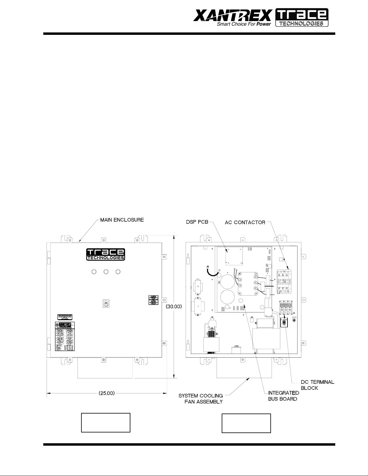
The major components of the PV-20208 are identified in Drawing No. 151121.
Main Enclosure
The enclosure (shown in Figure 1-1) is NEMA-4 rated. The PV-20208 enclosure contains the Inte-
grated Bus Board, output line filter (insuring that the PV-20208 line currents and voltages meet IEEE-
519 harmonic distortion requirements), control power transformers, and A/C contactor (PV-20208 A/
C output to the grid). Also found within the enclosure are the system protection devices (control power
circuit fuses). The front door of the enclosure contains the operator interface panel (three LED’s or
LCD and an on/off switch).
Figure 1-1
Figure 1-2

SECTION 1
PRODUCT DESCRIPTION
PV-20208 Photovoltaic Inverter
Operation and Maintenance Manual
Copyright 2000, Xantrex Technologies Inc./Trace Technologies Corp.
DOCUMENT: 151119
1-2
Integrated Bus Board
The PV-20208 design makes use of a fully integrated bus board as shown in Figure 1-2. The bus board
assembly is mounted to an aluminum extrusion heat sink, which mounts through an opening in the
back of the enclosure. The power electronics is comprised of a six pack of IGBT devices, mounted to
the heat sink. The bus board is mounted on top of the IGBT six pack device, and is supported through
a series of standoffs attached to the heat sink.
The bus board contains all of the necessary control functions to drive the (attached) switching transis-
tors. The bus board contains the following functional circuits: D/C control power supplies (+5V, +/-
15V and four isolated +15V sources for the IGBT’s), A/C and D/C high voltage measurement, A/C and
ground current measurements, contactor and indicator controls, discrete input sensing (on/off switch),
and closed loop PWM modulators. The bus board contains a micro-controller chip to perform the low-
level control functions associated with the collection of measurement and driving the pulse width
modulators.
A plug in DSP module controls the bus board. The DSP module is designed to the industry standard,
PC-104 specification, and is used to perform the majority of the calculations needed to control the bus
board. The most significant tasks are: control of PV-20208 electromechanical components and power
electronics converters, signal conditioning (digital filtering and transformations), and communication
with the operator interface panel and system sensors.
The PV array ties directly to the DC bus. The inverter controller manages the transfer of power between
the DC bus and the utility grid.
INTERCONNECTION STANDARDS COMPLIANCE
The PV-20208 has been tested and certified by Underwriters Laboratories to be in compliance with
UL1741 Static Inverters And Charge Controllers For Use In Photovoltaic Power Systems, as well
as IEEE-P929 Recommended Practice For Utility Interface Of Photovoltaic (PV) Systems.
IEEE-P929 provides guidance regarding equipment and functions necessary to ensure compatible op-
eration of photovoltaic systems which are connected in parallel with the electric utility. UL1741 is the
test procedure performed by Underwriters Laboratory on the PV-20208 to verify it meets the recom-
mendations of IEEE-P929. Refer to both documents for details of these recommendations and test
procedures.
CAUTION
The fuses within the PV-20208 are intended for protecting the PV-20208 control cir-
cuitry only. They are not intended to provide protection for the PV array or external
cabling.
SECTION 1
PRODUCT DESCRIPTION
PV-20208 Photovoltaic Inverter
Operation and Maintenance Manual
Copyright 2000, Xantrex Technologies Inc./Trace Technologies Corp.
DOCUMENT: 151119
1-3
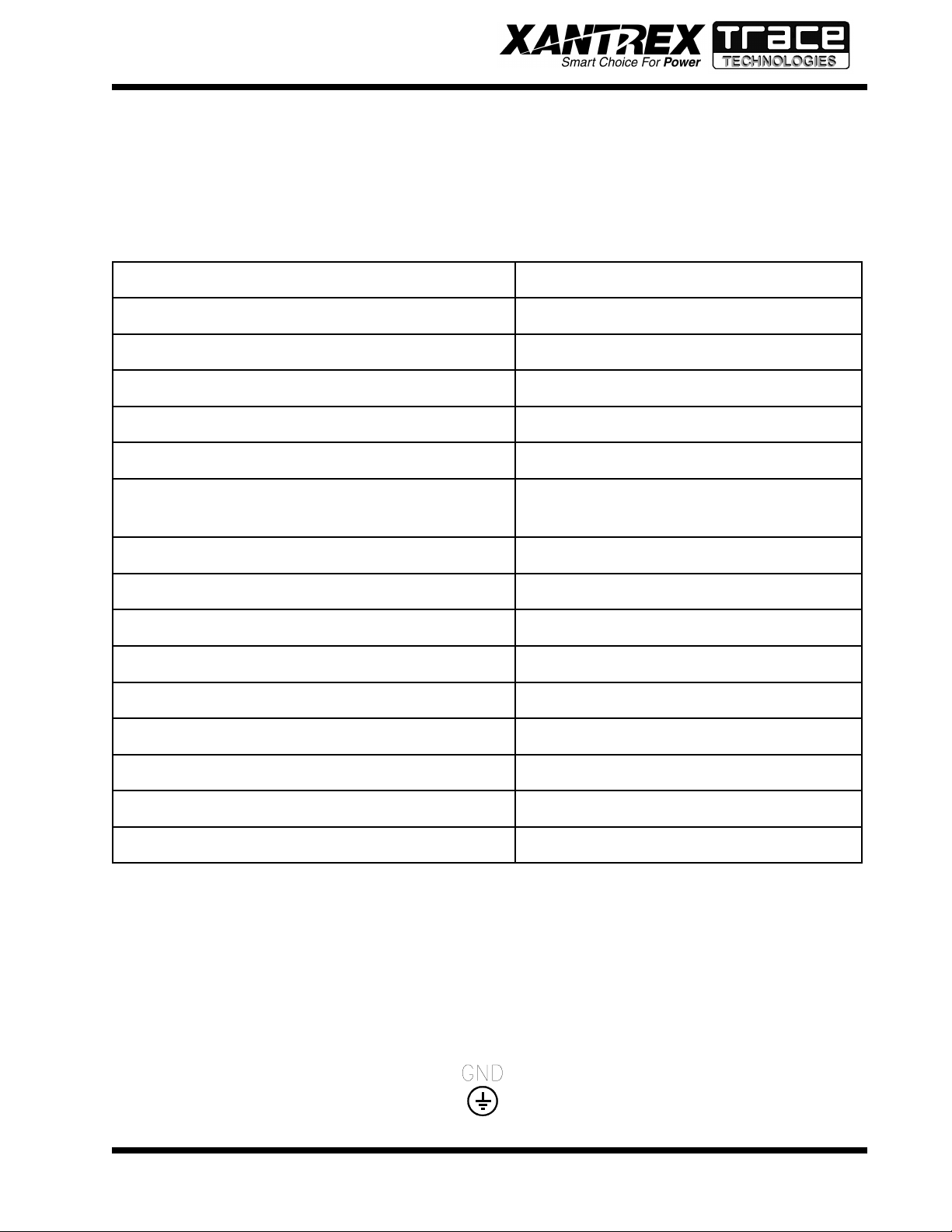
egatloVeniLCAlanimoN%01±,CAV802
tnerruCeniLCAmumixaM )egatlovenilwolta(SMRA86.16
ycneuqerFeniLlanimoNzH5.0±,zH06
daoLCAsuounitnoCCAv802@WK0.02
egnaRegatloVVPCDV006-033
tnerruCmumixaMVPCDA8.36
noitarugifnoCVP
ralop-ibro,dednuorgevitagenraloponoM
dnuorglartuen
erutarepmeTgnitarepO*C°05ot02-
erutarepmeTegarotSC°05ot04-
gnitaRerutarepmeTtneibmAmumixaMC°05
ytidimuHevitaleRgnisnednoc-noN,%59oT
noitavelEteef006,6evobadetareD
)sehcnini(snoisnemiD41X52X03
thgieW.sbl571.xorppA
epyTerusolcnE4AMEN
eliFgnitsiLLU653991E-eliF
EQUIPMENT SYMBOL
Chassis ground – Customer supplied system ground connection point. This symbol may be found near
a stud within the main enclosure. It is provided as a location to bond the electrical system equipment
ground.
*If ambient temperature is between -20 to 0° C, the unit must be powered up in standby for at least
one hour prior to going on-line.
SPECIFICATIONS
The PV-20208 has been designed for photovoltaic power systems, which operate within the following
specifications. Application of the PV-20208 in a manner inconsistent with these specifications may
cause damage to the PV-20208 and other system components, and is a violation of the terms of the
warranty.
DOCUMENT: 151119
SECTION 2
SAFETY
PV-20208 Photovoltaic Inverter
Operation and Maintenance Manual
Copyright 2000, Xantrex Technologies Inc./Trace Technologies Corp.
2-1
SAFETY FEATURES
Front Panel Indicators
The PV-20208 incorporates three colored LED indicators, used to show the current operating state of
the inverter. The indicators have the following meanings:
• Red: Fault Mode - The inverter has sensed an abnormal condition. To reset the unit (clearing the
fault condition), cycle the on/off switch (see below).
• Amber: Sleep Mode – The inverter is waiting for sufficient PV voltage to start the inverter.
• Green: Operator Mode - The inverter is active and generating A/C current.
On/Off Switch
The PV-20208 incorporates a maintained position on/off switch located on the front door of the enclo-
sure. Under normal conditions, the on/off switch in the on position. Turning the switch to the off
position will initiate a controlled shutdown of the PV-20208 and open the main contactor within the
unit. The PV-20208 is prevented from being restarted until the on/off switch is turned back to the on
position. Cycling the on/off switch will reset the PV-20208 and attempt to clear any system fault.
Main Enclosure Door
The front door of the PV-20208 main enclosure is pad lockable. It is recommended that the PV-20208
enclosure door be padlocked during normal operation.
Fault Reporting
Any fault conditions are reported to the operator interface. If the PV-20208 is equipped with LED’s,
the red LED will light and the green LED will flash the corresponding number of the fault. If the PV-
20208 is equipped with the LCD option, the LCD will display a text description of the fault. Refer to
Section 5, Troubleshooting, for detailed descriptions of system fault conditions.
PV Ground Fault Detection
The PV-20208 is equipped with ground fault detection circuitry and control. The single point of PV
The PV-20208 enclosure contains exposed high voltage conductors. The enclosure
door should remain closed, except during maintenance or testing. These servicing
instructions are for use by qualified personnel only. To reduce the risk of electric
shock, do not perform any servicing other than that specified in the operating
instructions unless you are qualified to do so. Do not open the cabinet door if
extreme moisture is present (rain or heavy dew).
WARNING
The PV-20208 does not incorporate a door interlock switch. Please make sure the
unit is powered down, and isolated from the utility grid and PV panels, prior to
opening the enclosure door. (Allow 5 minutes for any stored potentials to be dis-
charged, prior to opening the unit). The front door of the PV-20208 main enclosure
is pad lockable. It is recommended that the PV-20208 enclosure door be padlocked
during normal operation.
WARNING

DOCUMENT: 151119
SECTION 2
SAFETY
PV-20208 Photovoltaic Inverter
Operation and Maintenance Manual
Copyright 2000, Xantrex Technologies Inc./Trace Technologies Corp.
2-2
The terminals of the PV input may be energized if the arrays are energized. In
addition, allow 5 minutes for all capacitors within the enclosure to discharge after
disconnecting the PV-20208 from AC and DC sources.
WARNING
ISOLATION PROCEDURE
The following procedure should be followed to de-energize the PV-20208 for maintenance:
ANTI ISLAND PROTECTION
A digital phase-shift-loop (PSL) circuit is implemented in the DSP inverter controller to prevent
“Islanding” of the PV-20208.
The DSP continuously makes minor adjustments to the power factor phase angle above and below
unity. In the event of a utility outage, these adjustments destabilize the feedback between the inverter
and the remaining load, resulting in an over/under frequency or voltage condition. The PV-20208
then performs an orderly shutdown. The fault condition will remain until the utility voltage and
frequency have returned to normal for 5 minutes.
This method has been extensively tested and proven to exceed the requirements of UL 1741.
system ground must be routed through CT1 on the main control board (see section 3, installa-
tion and section 7, system schematic for further detail). Upon detection of 1.5 amps of ground
fault current, the PV-20208 executes an orderly shutdown, and annunciates a ground fault at the
operator interface. The PV-20208 will remain faulted until the ground fault is remedied and
cleared at the operator interface (see section 5, troubleshooting).
1. Turn the on/off switch to the off position.
2. Open the PV array disconnect switch (if present).
3. Open the AC interface disconnect (if present).
4. Open the isolation transformer circuit breaker.
5. Install lockout devices on the isolation transformer circuit breaker and PV disconnect switch (if
present).
SECTION 3
INSTALLATION AND INITIAL TURN-ON
PV-20208 Photovoltaic Inverter
Operation and Maintenance Manual
Copyright 2000, Xantrex Technologies Inc./Trace Technologies Corp.
DOCUMENT: 151119
3-1
ISOLATION TRANSFORMER REQUIREMENTS
The PV-20208 is required to have an isolation transformer wired between the inverter AC output and
the utility interconnection. Any standard dry-type isolation transformer is compatible with the PV-
20208 as long as the inverter side is rated for a minimum of 20KVA continuous duty.
Inverter Side Isolation Transformer Requirements
The inverter side transformer windings may be configured either delta or WYE, and must be rated for
208 VAC. Trace Technologies recommends using a delta wound transformer to avoid installation mis-
takes. If a WYE wound transformer is used to interface with the PV-20208, and the PV array is
grounded, the neutral (X0) must be left floating. If the neutral is tied to ground, the inverter will not
function properly , and may be damaged.
Utility Side Isolation Transformer Requirements
The utility side isolation transformer windings may be configured either delta or WYE, and must be
rated for the utility voltage at the point of utility inter-connection. Check with the utility of jurisdiction
when selecting an isolation transformer configuration. If a WYE wound transformer is used to interface
with the utility , it is not necessary to connect the neutral (X0) to ground. The PV-20208 is a balanced,
three phase, current sourcing inverter, and only operates with the presence of a stable utility voltage.
Single phase grounded loads which may be present between the transformer and utility, will maintain
their existing ground reference at the utility distribution transformer . Grounding the neutral of a WYE
wound transformer may create an “open delta” condition, depending on the utility configuration. This
condition may keep the PV-20208 from detecting a loss of phase condition on the utility system,
which may allow potentially lethal voltage to be present on the open phase wiring.
Contact your Xantrex/Trace Technologies distributor if you have any questions regarding isolation
transformer requirements.
Check with the local utility of jurisdiction when selecting the winding configura-
tion of the isolation transformer. Individual utilities may have unique require-
ments related to isolation transformer wiring. Some winding configurations may
keep the PV-20208 from detecting a loss of phase condition on the utility system
which may allow potentially lethal voltage to be present on the open phase wir-
ings.
WARNING
TORQUE AND WIRE GAUGE SPECIFICATIONS
The following torque specifications are to be used on all electrical interfaces made during installation
of the PV-20208.
eziStloBrokcolBlanimreTgnitteSeuqroT
1-6MmN9.5/.sblni25
23126tumwahS/zarreFmN6.31-3.2/sblni021-02
T orque Table
SECTION 3
INSTALLATION AND INITIAL TURN-ON
PV-20208 Photovoltaic Inverter
Operation and Maintenance Manual
Copyright 2000, Xantrex Technologies Inc./Trace Technologies Corp.
DOCUMENT: 151119
3-2
All wiring methods shall be in accordance with the National Electrical Code ANSI/
NFPA 70. All power conductors interfacing to the PV-20208 should be sized in
accordance with the National Electric Code ANSI/NFP A 70 and local codes. Large
gauge wire must have a minimum bend radius dependent upon the wire gauge
(refer to the National Electric Code, Article 373-6B). Take care to keep the wire
bundles away from any sharp edges which may damage wire insulation over time.
Trace Technologies recommends using No. 6 AWG, 105 degrees C, minimum,
copper wire for all connections with the PV-20208.
CAUTION
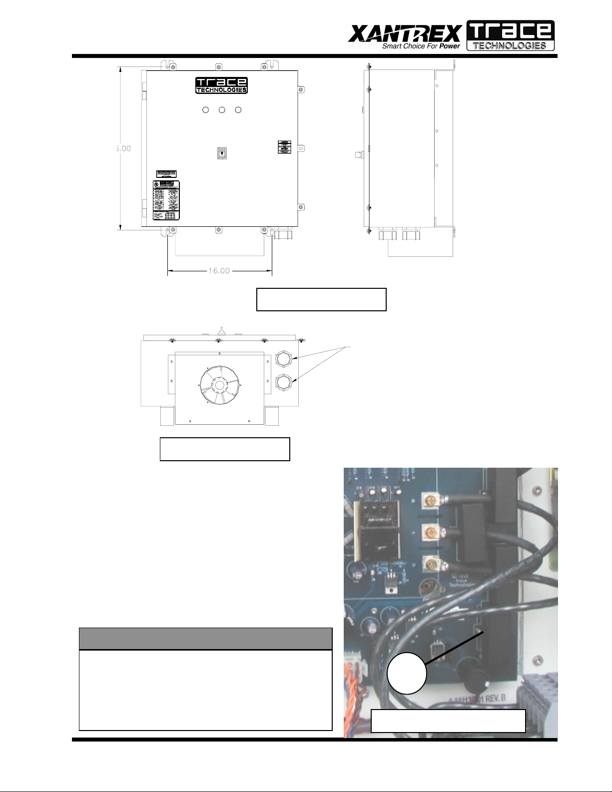
Ventilation Considerations
1. Maintain a minimum 6” clearance above and below the PV-20208 for proper cooling fan operation.
2. Maintain a minimum 1” clearance to the left and right of the PV-20208.
Installation
1. The unit must be mounted at least 3’ off the ground, and 12” above any horizontal surface.
2. Screw two 3/8” x 3-1/2” long lag bolts into existing studs in the wall (16-inch mounting center) at
lower mounting level on PV-20208. Lag bolts should be horizontally level with each other. Leave
a minimum of 1” of bolt protruding from the wall.
3. Place the PV-20208 bottom mounting ears, shown in Figure 3-1 and Figure 3-2 onto installed lag
bolts. (See following page.)
4. Hold the unit against wall and install upper lag bolts (3/8” x 3-1/2”). Tighten bolts firmly.
5. Tighten lower lag bolts while unit is held in place.
6. Install two 1-1/2” liquid tight connectors (included with the PV-20208) where shown in
Figure 3-3. (See following page.)
INSTALLATION INSTRUCTIONS
noitanimreTGWAegnaReriW
)CA(rotcatnoC01#-3#
)CD(kcolBnoitubirtsiD41#-0/2
The following table shows acceptable wire gauges to be connected to the PV-20208 AC and DC
inputs.
Wire Gauge Table
Figure 3-1
SECTION 3
INSTALLATION AND INITIAL TURN-ON
PV-20208 Photovoltaic Inverter
Operation and Maintenance Manual
Copyright 2000, Xantrex Technologies Inc./Trace Technologies Corp.
DOCUMENT: 151119
3-3
Figure 3-2
Figure 3-3
LIQUID TIGHT CONNECTORS
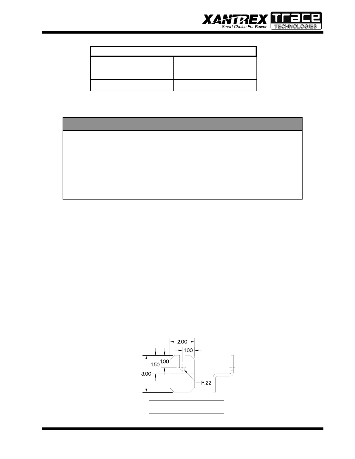
Array Grounding and Ground Fault Detection
If grounding the PV array is required for monopolar or
bipolar arrays, jumper TB1-2 to a (PV-) cabinet ground
stud. If ground fault detection is required, route this
jumper through CT1 located on the lower right hand
corner of the control board (see the system schematic
for further detail). This must be the only point of PV
grounding for the PV-20208 and the ground fault
detection system to function properly .
CONTROL BOARD & CT1
CT1
The input and output circuits are isolated from
the enclosure, and that system grounding, if re-
quired by sections 690-41 and 690-42 of the Na-
tional Electric Code, ANSI/NFPA 70, is the
responsibiliy of the installer.
CAUTION
SECTION 3
INSTALLATION AND INITIAL TURN-ON
PV-20208 Photovoltaic Inverter
Operation and Maintenance Manual
Copyright 2000, Xantrex Technologies Inc./Trace Technologies Corp.
DOCUMENT: 151119
3-4
To reduce the risk of fire, connect only to a cir-
cuit provided with 90 amperes maximum branch
circuit overcurrent protection in accordance with
the National Electrical Code, ANSI/NFPA 70.
CAUTION
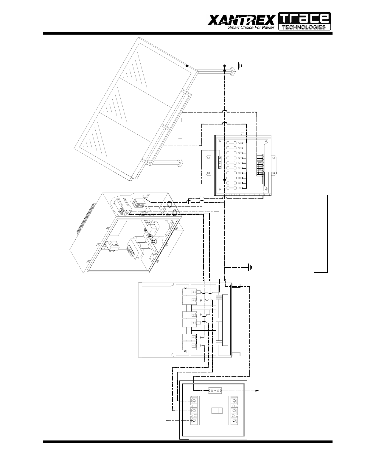
INTERCONNECTION WIRING
The following wires for connecting the PV-20208 to ex-
ternal devices are not provided by Xantrex/Trace Tech-
nologies: (See wiring diagram on the following page.)
Phase-Sequencing
The PV-20208 is equipped with an automatic phase-
detection control algorithm. This allows the utility
interface conductors to be connected in any sequence
convenient at the time of installation. Upon system
initialization at power-up, the PV-20208 determines
the phase sequence of the utility connection and
configures the modulator drivers accordingly .
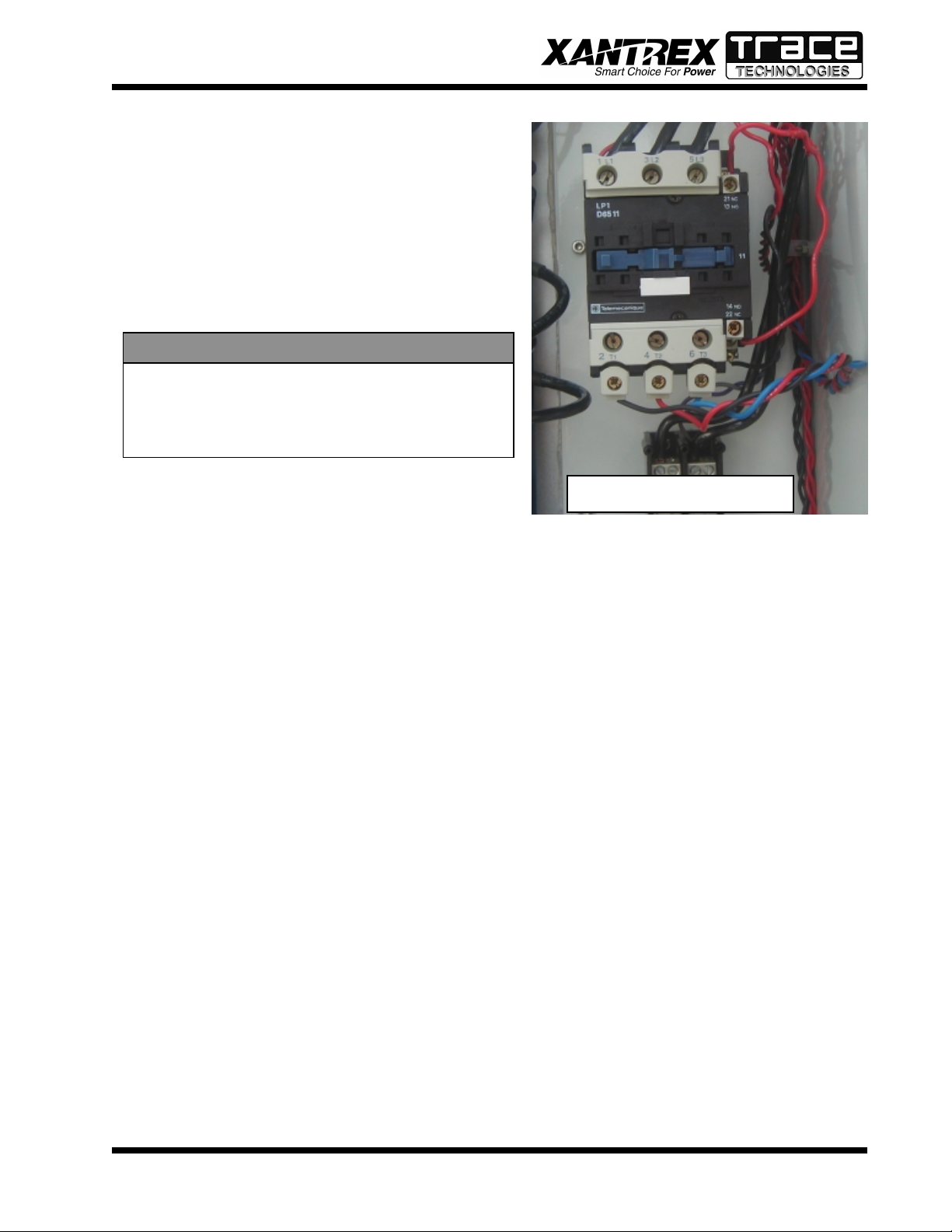
• 3-Phase 208 VAC inverter output (main contactor, see picture) to terminals of the 208 VAC delta
side of isolation transformer. If the inverter side of the isolation transformer is configured
WYE and the PV array is grounded, the neutral must be left floating. Ground loops will
exist when the inverter starts switching, which will cause the inverter to shut down due to
phase over-currents and may result in damage to the PV-20208. Also, insure that this
neutral is not bonded to the isolation transformer frame.
• System ground to the isolation transformer chassis ground.
• Isolation transformer grid side terminals to line circuit breaker (or the AC disconnect switch if
present).
• PV frame ground to PV-20208 enclosure chassis ground stud.
• PV-20208 enclosure chassis ground stud to the electrical distribution system ground.
• PV+ to the inverter enclosure terminal block TB1-1.
• PV- to the inverter enclosure terminal block TB1-2.
Install all wires listed above. Refer to the system schematics in Section 7 for more detailed terminal
locations.
MAIN CONTACTOR
SECTION 3
INSTALLATION AND INITIAL TURN-ON
PV-20208 Photovoltaic Inverter
Operation and Maintenance Manual
Copyright 2000, Xantrex Technologies Inc./Trace Technologies Corp.
DOCUMENT: 151119
3-5
Wiring Diagram
Frame
Ground
Line Circuit
Breaker
Isolation
Transformer
PV-20208
Inverter
To Single Point Electrical
Distribution System Ground
PV Array
Trace Combiner Box
(Optional)
A
B
C
X1 H1 X2 H2 X3 H3
X0
PV+
PV-
 Loading...