


Whirlpool QCAM2730YQ, CAW2762KQ, CAE2761KQ, CAW2762RQ, CAW2752RQ Installation Instructions
...Installation Instructions
IMPORTANT: |
|
|
|
|
|
|
|
|
|
|
|
|
|
|
|
||
|
|
|
|
|
|
|
||
COMMERCIAL |
||||||||
Read and save |
||||||||
these instructions |
WASHER |
|||||||
Part No. 8524739C
IMPORTANT: |
120-volt, 60-Hz Models |
Installer:Leave Installation Instructions |
|
with the owner. |
|
Owner:Keep Installation Instructions for |
|
future reference. |
|
SaveInstallation Instructions for local |
|
electrical inspector’s use. |
|
www.whirlpoolcommerciallaundry.com |
|
®
COMMERCIAL LAUNDRY PRODUCTS

Before you start...
Your safety and the safety of others are very important.
We have provided many important safety message in this manual and on your appliance. Always read and obey all safety messages.
This is the safety alert symbol.
This symbol alerts you to potential hazards that can kill or
hurt you and others.
All safety messages will be preceded by the safety alert symbol and the word “DANGER” or “WARNING”. These words mean:
 DANGER
You can be killed or seriously injured if you don’t immediately follow instructions.
 WARNING
You can be killed or seriously injured if you don’t follow instructions.
All safety messages will tell you what the potential hazard is, tell you how to reduce the chance of injury, and tell you what can happen if the instructions are not followed.
IMPORTANT SAFETY INSTRUCTIONS
WARNING: To reduce the risk of re, electric shock, or injury to persons when using your washer, follow basic precautions, including the following:
•Read all instructions before using the washer.
•Do not wash articles that have been previously cleaned in, washed in, soaked in, or spotted with gasoline, dry-cleaning solvents, other ammable or explosive substances as they give o vapors that could ignite or explode.
•Do not add gasoline, dry-cleaning solvents, or other ammable or explosive substances to the wash water. These substances give o vapors that could ignite or explode.
•Under certain conditions, hydrogen gas may be produced in a hot water system that has not been used for 2 weeks or more. HYDROGEN GAS IS EXPLOSIVE. If the hot water system has not been used for such a period, before using a washing machine, turn on all hot water faucets and let the water ow from each for several minutes. This will release any accumulated hydrogen gas. As the gas is ammable, do not smoke or use an open ame during this time.
•Do not allow children to play on or in the washer. Close supervision of children is necessary when the washer is used near children.
•Before the washer is removed from service or discarded, remove the lid.
•Do not reach into the washer if the tub or agitator is moving.
•Do not install or store this washer where it will be exposed to the weather.
•Do not tamper with controls.
•Do not repair or replace any part of the washer or attempt any servicing unless speci cally recommended in the Owner's Manual or in published user-repair instructions that you understand and have the skills to carry out.
•See Page 4 of this booklet for recommended grounding instructions.
SAVE THESE INSTRUCTIONS
2
instructions are not followed.
Check location where washer will be installed. Proper installation is your responsibility. Make sure you have everything necessary for correct installation.
Do Not store or operate washer below 32°F (0°C) (some water may remain in washer).
Untape and open washer lid. Remove packages and hoses from washer.
No. T20 TORX®† screws
Single washer |
|
|
installations require |
Grounded |
|
12-inch (300 mm) |
||
electrical outlet |
||
minimum risers to |
||
is required. See |
||
provide an air |
||
Electrical |
||
cushion and |
||
requirements. |
||
avoid noise and |
||
|
||
damage to valves. |
|
Level -oor: Maximum slope under washer — 1 inch (25 mm).
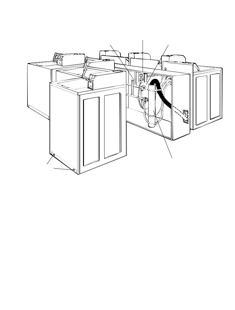
Front access to the pump area is |
A -oor drain should be |
|
available by removing 2 No. T20 |
provided under the bulkhead. |
|
Torx®† screws and then removing the |
Prefabricated bulkheads with |
|
front panel. |
electrical outlets, water supply |
|
IMPORTANT: Observe all governing |
lines, and drain facilities should |
|
be used only where local |
||
codes and ordinances. |
||
codes permit. |
||
|
Hot and cold water faucets: Must be within 4 feet (1.2 meters) of the back
of the washer and provide water pressure 10 - 100 PSI (69-690 kPa). A pressure reduction valve should be used in the supply line where inlet pressure entering the building exceeds 100 PSI (690 kPa) to avoid damage to the washer mixing valve.
Water heater: Set to deliver 120°F (49°C) water to the washer.
Standpipe drain system: Needs a twoinch (50 mm) minimum carry-away capacity of 17 gallons (64.4 liters) per minute. Top of standpipe must be at least 39 inches (990 mm) high and no higher than 72 inches (1.83 m) from bottom of washer.
IMPORTANT: Floor must be sturdy enough to support loaded washer weight of 315 pounds (143 Kg).
† ® TORX is a registered trademark of Saturn Fasteners, Inc.
† ® TORX is a registered trademark of Saturn Fasteners, Inc.
3
Recessed area |
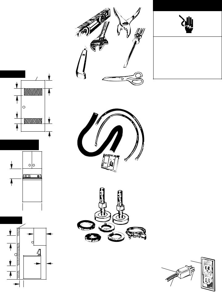
Tools needed for |
instructions |
installation: |
This washer may be installed in a recessed area or closet.
The installation dimensions shown are the minimum spaces allowable. Additional spacing should be considered for ease of installation and servicing. If closet door is installed, the minimum air openings in top and bottom of door are required. Louvered doors with air openings in top and bottom are acceptable. Companion appliance spacing
should be considered.
Pliers
Wrench
Minimum installation spacing
Front view |
Closet door |
|
|
|
3" |
|
(76 mm) |
48 sq. in. |
|
(3.10 sq. m) |
|
24 sq. in. |
|
(1.55 sq. m) |
|
|
3" |
|
(76 mm) |
Flat-blade screwdriver
Utility knife
Parts supplied for installation:
Front view (door not shown)
17" (430 mm)
0"


 0"
0"
Side view
Closet door
48 sq. in. |
14" |
|
(350 mm) |
||
(3.10 sq. m) |
max. |
|
24 sq. in. |
4" |
|
(100 mm) |
||
(1.55 sq. m) |
||
min. |
||
|
 1" (25 mm) min.
PAGE 3
4
Remove parts from packages. Check that all parts were included.
1 hose clamp
2 inlet hoses
4 at water hose washers
2 front-leveling legs with nuts
1 drain hose
Electrical requirements
 WARNING
Electrical Shock Hazard
Plug into a grounded 3-prong outlet. Do not remove ground prong.
Do not use an adapter.
Do not use an extension cord.
Failure to follow these instructions can result in death, fire, or electrical shock.
If codes permit and a separate ground wire is used, it is recommended that a quali ed electrician determine that the ground path is adequate.
Do Not ground to a gas pipe.
Check with a quali ed electrician if you are not sure the washer is properly grounded.
Do Not have a fuse in the neutral or ground circuit.
A 120-volt, 60-Hz, AC-only, 15or 20-ampere fused electrical supply is required. (Time-delay fuse or circuit breaker is recommended.) It is recommended that a separate circuit serving only this appliance be provided.
Grounding instructions
This appliance must be grounded. In the event of a malfunction or breakdown, grounding will reduce the risk of electric shock by providing a path of least resistance for the electric current. This appliance is equipped with a cord having an equipment-grounding conductor and a grounding plug. The plug must be plugged into an appropriate outlet that is properly installed and grounded in accordance with all local codes and ordinances.
WARNING – Improper connection of the equipment-grounding conductor can result in a risk of electric shock. Check with a quali ed electrician or serviceman if you are in doubt as to whether the appliance is properly grounded. Do not modify the plug provided with the appliance – if it will not t the outlet, have a proper outlet installed by a quali ed electrician.
3-prong |
3-prong grounding- |
type outlet |
|
grounding |
|
plug |
|
Grounding prong
Power supply cord

Now start...
 WARNING
Excessive Weight Hazard
Use two or more people to move and install washer.
Failure to do so can result in back or other injury.
Shipping tape
Pull the strap completely out of the washer.
1. Remove tape that covers shipping strap. Pull to completely remove the shipping strap with 2 cotterpins from the inside
of the washer.
Pull rmly to remove the end of shipping strap from the back of the washer. The shipping strap plug must be completely removed from the washer for the self-leveling legs to be released.
Save the shipping strap for use in Step 6.
Use new hoses and washers that came with your Whirlpool washer.
Replace inlet hoses after 5 years of use to reduce the risk of hose failure. Inspect and replace inlet hoses if bulges, kinks, cuts, wear, or leaks are found. When replacing your inlet hoses, mark the date of replacement on the label with a permanent marker.
Coupling Washer
2.Insert a at washer into each end of the inlet hoses. Check that washers are rmly seated in couplings.
Inlets are plastic. Do Not strip or crossthread.
Cold water inlet valve
Hot water inlet valve
3.Attach hose to bottom inlet valve opening rst. Then second hose to top inlet. Tighten couplings by hand; then use pliers to make an additional two-thirds turn.
4.Move washer close to nal position. Put “hook” end of drain hose into standpipe. Estimate length of drain hose needed when washer is innal position. Hose must be cut exactly to length so “hook” end is held tightly over edge of standpipe. If drain hose is too long, cut straight end
of hose. (Do Not cut “hook” shaped end of drain hose.)
DO NOT FORCE EXCESS LENGTH OF DRAIN HOSE DOWN THE STANDPIPE. THIS COULD CAUSE SIPHONING. See Step 6.
5.Place hose clamp over washer drain connector. Push drain hose onto washer connector. Use pliers to open clamp and slide clamp over drain hose. Check for good t.
16" (406 mm)
6.Measure and mark a point approximately 16 inches (406 mm) from the plug end of the shipping strap. Cut this shipping strap at this point.
Check that hose is not twisted or kinked and is
securely in place.
Put “hook” end of drain hose into standpipe. Tightly wrap the shipping strap around the
standpipe. Push plug into the nearest hole in the shipping strap.
7.Before
attaching water inlet hoses, run
water through both faucets into a bucket. This will get rid of particles
in water lines that might clog hoses.
Mark which is the hot water faucet.
8.Attach bottom hose (inlet marked “H”) to hot water faucet. Attach top hose (inlet marked “C”) to cold water faucet. Tighten coupling to faucet by hand; then use pliers to make nal two-thirds turn.
9.Stack two corner posts on top of each other. Tilt washer backwards and insert corner posts 3 inches (76 mm) in from one side of washer as shown.
Repeat with other corner posts on other
side of washer.
5
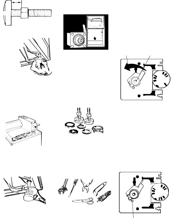
1/2" (13 mm)
Base
Nut
10.Use legs and nuts from parts package. Screw nut down to within 1/2 inch (13 mm) of
base.
11.
Insert legs into correct holes at each front corner
of washer until nuts touch washer. Do Not tighten nuts until Step 14.
12.Tilt washer backward and remove corner posts. Gently lower washer to oor.
Move washer to its permanent location. Remove cardboard or hardboard from under washer.
13.Tilt washer forward raising back legs 1 inch (25 mm) o of oor. To adjust rear self-leveling legs, gently lower washer to oor. Check levelness of the washer by placing a carpenter’s level on top of the washer, rst side to side; then front to back.
14 If washer is not level, adjust the front legs up or down. Make nal check with level.
When washer is level, use wrench to turn nuts on front legs up tightly against washer base. If nuts are not
tight against washer base, the washer may vibrate.
NOTE: If the coin slide mechanism has already been installed, skip this step and proceed to Step 16.
15.Remove the service door of the meter case. Lift the service door up at the back and remove. Install money accepting device (refer to manufacturer’s instructions for proper installation). For washers using coin slides, use adapter kit (provided with washer). Replace meter case service door.
16.CHECK ELECTRICAL REQUIREMENTS. BE SURE YOU HAVE CORRECT ELECTRICAL SUPPLY AND RECOMMENDED GROUNDING METHOD.
17.Check that all parts are now installed. See parts list, Page 4. If there is an extra part, go back through steps to see which step was skipped.
18.Turn on water faucets and check for leaks. Tighten couplings if there is leaking. Do Not overtighten; this could cause damage to faucets.
19.Check that you have all of your tools. Check that the shipping strap was removed from the back of the washer and used to secure the drain hose.
If entire strap is not removed, washer may vibrate and be noisy.
20.Plug power supply cord into grounded outlet.
21.Electromechanical Models Only. Check the wash cycle time. The washer has a 9-minute wash in the Normal Cycle. Remove the timer from the meter case of the washer to manually start the timer. Start the washer and allow it to complete the Normal cycle.
Rotate
counterclockwise Timer "off" position only.
Timer-front view
Timers can be started by turning the clutch assembly counterclockwise until the washer starts to ll with water.
22.If the washer fails to start or does not give the proper washer cycle time, the clutch assembly of the timer can be adjusted. Remove the timer from the meter case. Adjust the clutch assembly screw clockwise if the washer does not start after the coin slide mechanism has been fully actuated in or out. Adjust the clutch assembly counterclockwise if the washer segment of the Normal cycle was less than 9 minutes.
Timer clutch adjustment screw
6
 Loading...