


Whirlpool EGN 4400 SW, EGZH 4400 IN, EGN 3200/02, EGZH 5400 IN, EGN 5400 IN User Manual
...GB |
|
|
TABLE OF CONTENTS |
|
|
|
|
|
|
|
|
INSTALLATION |
|
PAGE 13 |
|
||
|
|
|
|
|
|
ELECTRICAL CONNECTION |
PAGE 14 |
|
|||
|
|
|
|
|
|
BEFORE USING THE OVEN |
PAGE 15 |
|
|||
|
|
|
|
|
|
PROTECTING THE ENVIRONMENT |
PAGE 15 |
|
|||
|
|
|
|
|
|
PRECAUTIONS AND GENERAL RECOMMENDATIONS PAGE 15 |
|
||||
|
|
|
|
|
|
OVEN ACCESSORIES |
PAGE 16 |
|
|||
|
|
|
|
|
|
COOKING CHART |
|
PAGE 17 |
|
||
|
|
|
|
|
|
CLEANING THE OVEN AND ACCESSORIES |
PAGE 18 |
|
|||
|
|
|
|
|
|
TROUBLESHOOTING GUIDE |
PAGE 19 |
|
|||
|
|
|
|
|
|
AFTER SALES SERVICE |
PAGE 20 |
|
|||
|
|
|
|
|
|
12
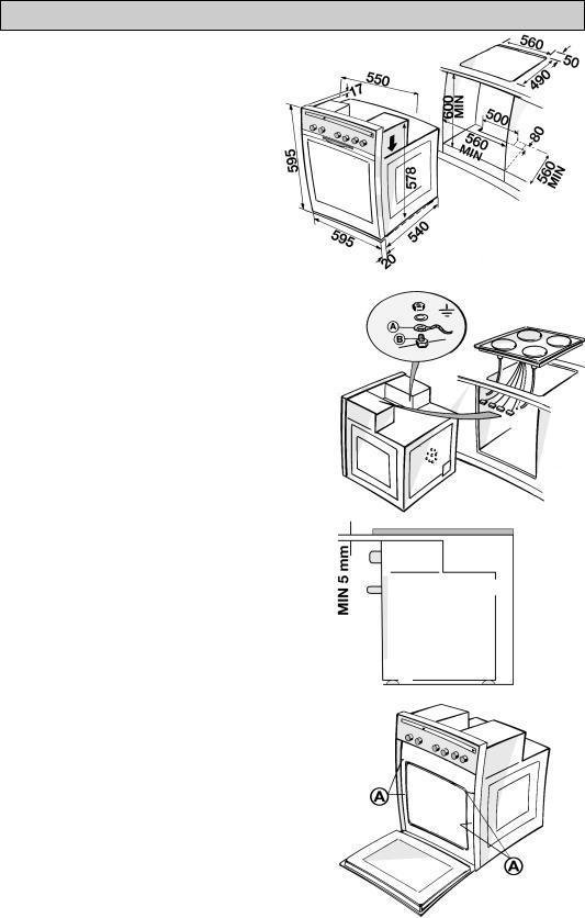
INSTALLATION
Technical information for the installer
•After removing the oven from its packaging, before making the connections place it on the polystyrene foam base to protect it from damage.
•Do not attempt to lift the oven by the handle. Lift at the sides as shown in the figure
(see arrow).
•Check that the appliance has not been damaged in transit.
•Oven dimensions and kitchen unit dimensions are shown in the opposite figure.
•Kitchen units in contact with the oven must be heat resistant (80°C min).
•Carry out the electrical connections between cooktop and oven (see chapter “Electrical Connection”).
•Install the oven in the housing, lifting it at the sides, taking care not to trap the wires of the electrical supply cable.
•For correct ventilation, follow the ventilation opening directions shown in the figure
(at least 500 x 80 mm or an equivalent area). Also provide for at least 5 mm clearance between the top of the oven and the lower edge of the worktop. This space must not be obstructed by cross rails or other structural elements.
•Secure the oven to the kitchen unit with screws (A) as shown.
13

INSTALLATION
•Warning: Do not connect to the power supply before you have finished connecting the oven and the cooktop.
•Make sure the oven is installed and connected to the electricity supply by a qualified technician in accordance with the manufacturer’s instructions and in compliance with local regulations.
•The installer is responsible for the correct electrical connection of the oven and the observance of the relative safety prescriptions.
•The oven must be connected to the electricity supply by means of an all-pole disconnect switch with minimum contact gap of 3 mm.
•The appliances must be earthed by law.
•Do not use multiple plug adapters or extension leads.
•After the oven has been installed, the electrical components must be inaccessible.
ELECTRICAL CONNECTION
See separate installation instructions supplied with the cooktop.
Electrical connection between different models of hobs and oven
Attention: The figures represent the right hand |
B |
|
B |
|
|
||
section of the oven, seen from the top, with the |
|
C |
C |
observer standing in front of the oven door. |
|
|
|
|
|
|
•Put clamp “B” into the first holes of junction block “C” starting from the left (as shown).
•Connect the earth wire (D) of the cooktop to the oven (E) as illustrated.
B
C
•Mount the corresponding knobs in the
control panel last |
.. |
4 gas burners hob: position of the knobs in the front controls hob
3 gas burners/1 electric hot plate hob: position of the knobs in the front controls hob
Glass ceramic hob: position of the knobs in the front controls hob
Glass ceramic hob (with 2 double cooking zones): position of the knobs in the front controls hob
14
 Loading...