


DU800DWG
Whirlpool DU800DWG, DU801DWG, DU805DWG, DU810DWG, DP840DWG Manual
...
CONSUMER SERVICES TECHNICAL
EDUCATION GROUP PRESENTS
1998 DISHWASHERS
Servicing and Troubleshooting
MODELS
DU800DWG DU801DWG DU805DWG
DU810DWG DP840DWG DU840DWG
KD-10
DU850DWG DU890DWG DU910PFG
DP920PFG DU920PFG GU940SCG
GU960SCG GU980SCG
JOB AID
Part No. 4322430
I

INTRODUCTION
This Job Aid,
specific information for the installation, service and repair of 1998 Whirlpool Dishwashers.
“1998 DISHWASHERS, Servicing and Troubleshooting
cent information on design, features, troubleshooting, service and repair procedures.
“1998 DISHWASHERS, Servicing and Troubleshooting
,” has been compiled to provide the most re-
,” (Part No. 4322430) provides
GOALS AND OBJECTIVES
The goal of this Job Aid is to provide detailed information that will enable the service technician to
properly diagnose malfunctions and repair the 1998 lineup of Dishwashers.
The objectives of the Job Aid are:
The service technician will -
• Understand proper safety precautions.
• Successfully troubleshoot and diagnose malfunction.
• Successfully perform necessary repairs.
• Successfully return the dishwasher to proper operational status.
CORPORATION
WHIRLPOOL CORPORATION ASSUMES NO RESPONSIBILITY
FOR ANY REPAIRS MADE ON OUR PRODUCTS BY ANYONE
OTHER THAN AUTHORIZED SERVICE TECHNICIANS.
© 1998 Whirlpool Corporation, Benton Harbor, MI 49022
II

TABLE OF CONTENTS
INTRODUCTION. . . . . . . . . . . . . . . . . . . . . . . . . . . . . . . . . . . . . . . . . . . II
T ABLE OF CONTENTS. . . . . . . . . . . . . . . . . . . . . . . . . . . . . . . . . . . . III
SAFETY . . . . . . . . . . . . . . . . . . . . . . . . . . . . . . . . . . . . . . . . . . . . . . . . IV
SECTION ONE
DURA WASH MODELS W/ SOIL SETTLER AND TELESCOPING TOWER
Model: DU800DWG, DU801DWG, DU805DWG, DU810DWG, DP840DWG,
DU840DWG, DU850DWG, DU890DWG
Theory of Operation . . . . . . . . . . . . . . . . . . . . . . . . . . . . . . . . . . . . . . . . . . . 1
Component Access . . . . . . . . . . . . . . . . . . . . . . . . . . . . . . . . . . . . . . . . . . . . 3
Solutions to Common Problems . . . . . . . . . . . . . . . . . . . . . . . . . . . . . . . . . 13
Troubleshooting Guide . . . . . . . . . . . . . . . . . . . . . . . . . . . . . . . . . . . . . . . . 15
T echnical Information . . . . . . . . . . . . . . . . . . . . . . . . . . . . . . . . . . . . . . . . . . 16
SECTION TWO
POWER CLEAN FIL TER MODELS W/ TOWER W ATER FEED
Models: DU910PFG, DP920PFG, DU920PFG
Theory of Operation . . . . . . . . . . . . . . . . . . . . . . . . . . . . . . . . . . . . . . . . . . . 27
Component Access . . . . . . . . . . . . . . . . . . . . . . . . . . . . . . . . . . . . . . . . . . . . 28
Troubleshooting Guide . . . . . . . . . . . . . . . . . . . . . . . . . . . . . . . . . . . . . . . . 33
T echnical Information . . . . . . . . . . . . . . . . . . . . . . . . . . . . . . . . . . . . . . . . . . 34
SECTION THREE
POWER CLEAN FILTER MODELS W/ INTERNAL W ATER FEED
Models: GU940SCG, GU960SCG, GU980SCG
Theory of Operation . . . . . . . . . . . . . . . . . . . . . . . . . . . . . . . . . . . . . . . . . . . 43
Component Access . . . . . . . . . . . . . . . . . . . . . . . . . . . . . . . . . . . . . . . . . . . .44
Diagnostics . . . . . . . . . . . . . . . . . . . . . . . . . . . . . . . . . . . . . . . . . . . . . . . . 49
Troubleshooting . . . . . . . . . . . . . . . . . . . . . . . . . . . . . . . . . . . . . . . . . . . . . . 50
T echnical Information . . . . . . . . . . . . . . . . . . . . . . . . . . . . . . . . . . . . . . . . . . 51
SECTION FOUR
Installation Considerations
Custom Door Panel Conversion . . . . . . . . . . . . . . . . . . . . . . . . . . . . . . . . . 55
Floor Mount Kit . . . . . . . . . . . . . . . . . . . . . . . . . . . . . . . . . . . . . . . . . . . . . . . 59
This Service Manual is accompanied by a companion video presentation,
SERVICING AND TROUBLESHOOTING
1998 DISHWSHERS
Part No. 4322329
III

-- NOTES --
IV
DURAWASH MODELS WITH
SOIL SETTLER AND TELESCOPING TOWER
THEORY OF OPERATION
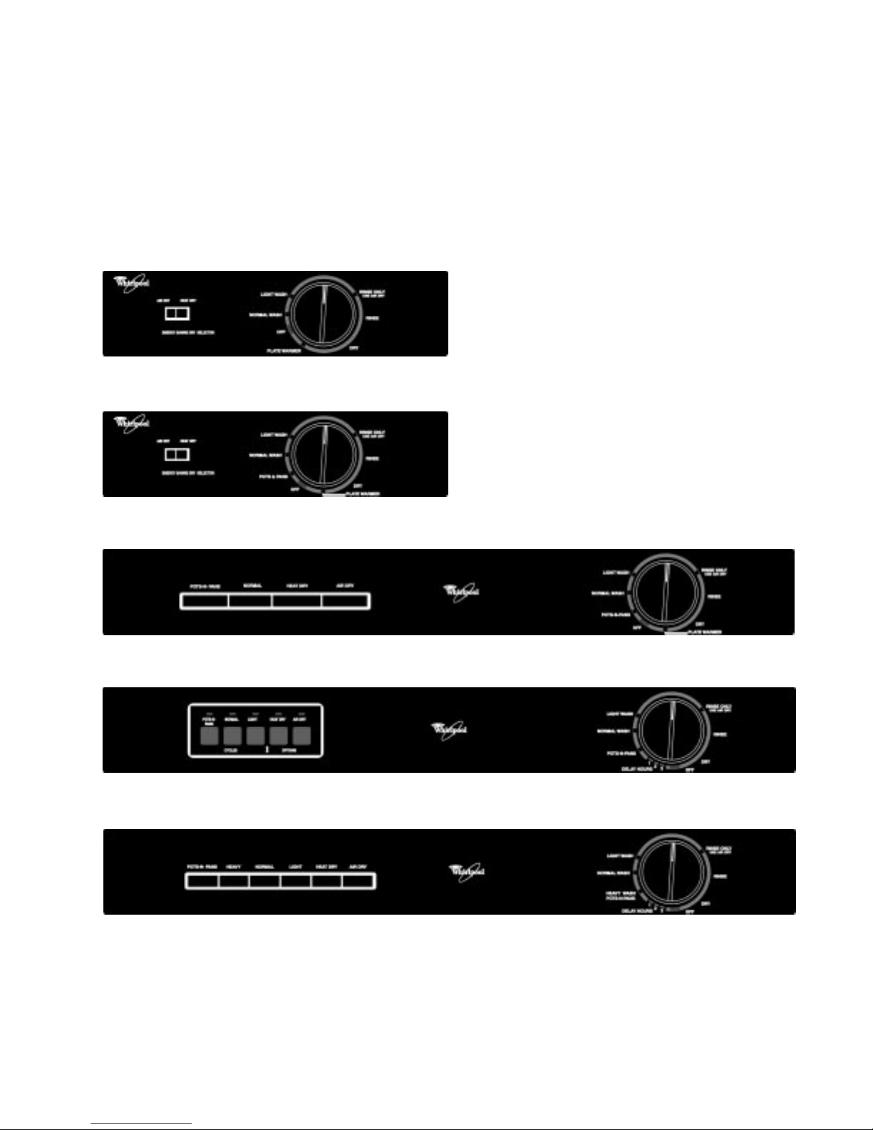
Console Configuration
DU800DWG, DU801DWG, DU805
DU810DWG
Section One
DU840DWG, DP840DWG
DU850DWG
DU890DWG
1
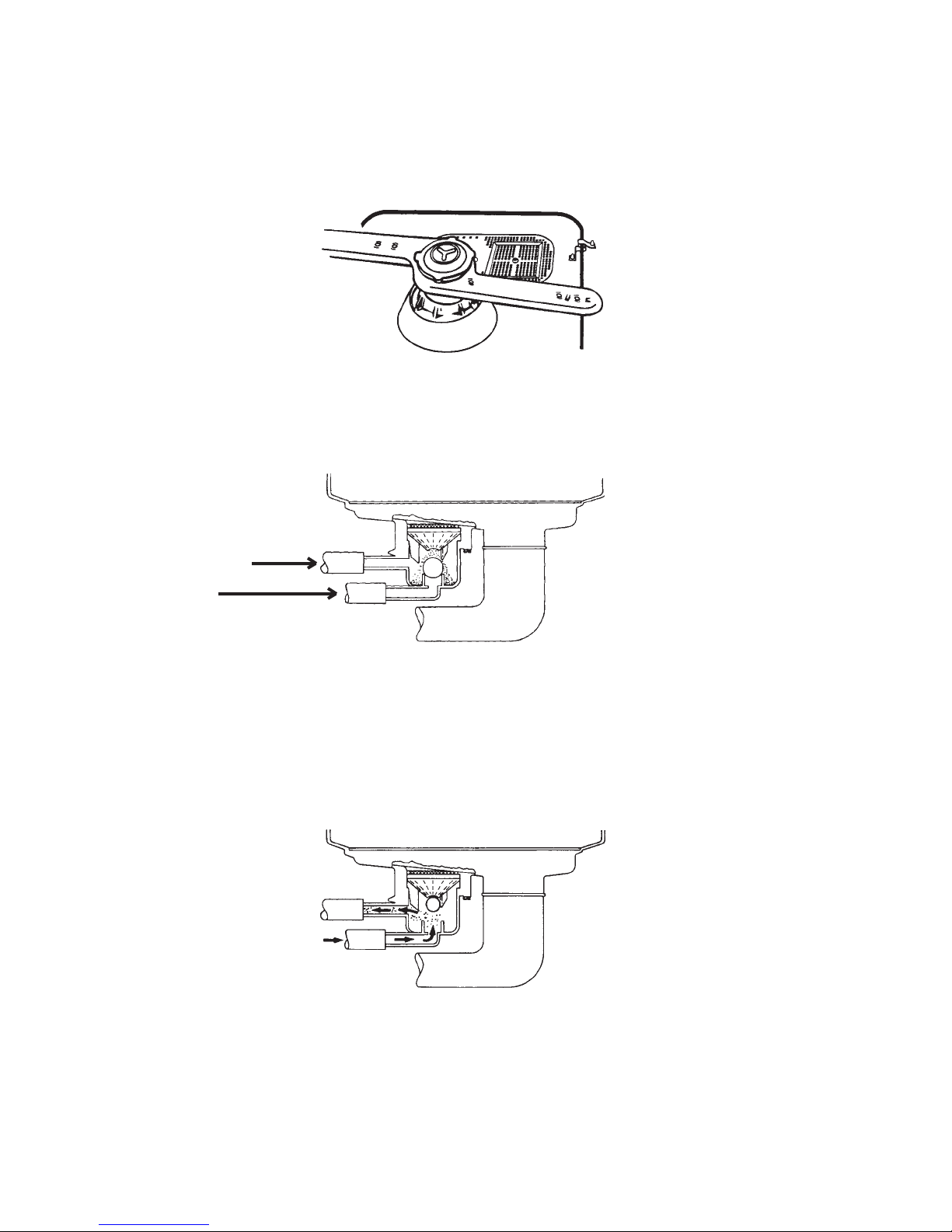
Special Feature
Soil Settler
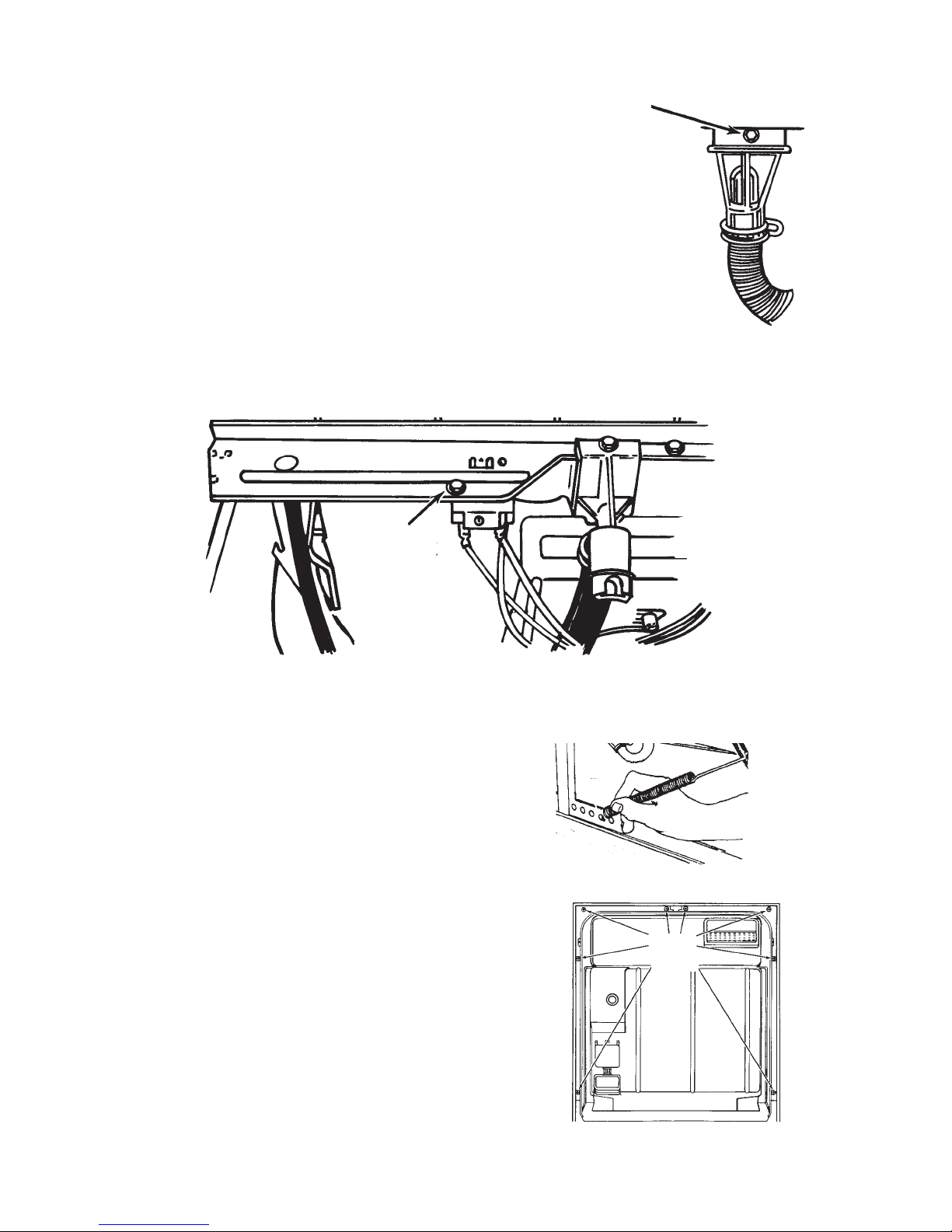
This model is equipped with a soil settler system. The inlet to the soil settler funnel is located to the
right and just behind the lower spray arm assembly.
Since this inlet is located in an area that is relatively free of water turbulence, food particles washed
from the dishes can collect in this area and fall through the funnel and accumulate in the collector .
1-2)
Food particles continue to collect as long as the dishwasher is in the Wash mode.
(Fig. 1-1)
Fig. 1-1
(Fig.
COLLECTOR
PUMP INLET
HOSE
Fig. 1-2
When the Wash cycle is finished, the dishwasher will reverse the direction of the motor and enter the
Drain mode. Water is pumped into the port at the bottom of the soil collector during the Drain cycle
causing the ball in the collector to rise against the opening in the bottom of the funnel. Water flows
through and out of the collector through the top port and into the drain line.
(Fig. 1-3)
Food particles
collected during the Wash cycle are carried out with the drain water. When the Drain cycle ends and
the pump stops running, the ball settles to the bottom of the collector.
Fig. 1-3
2
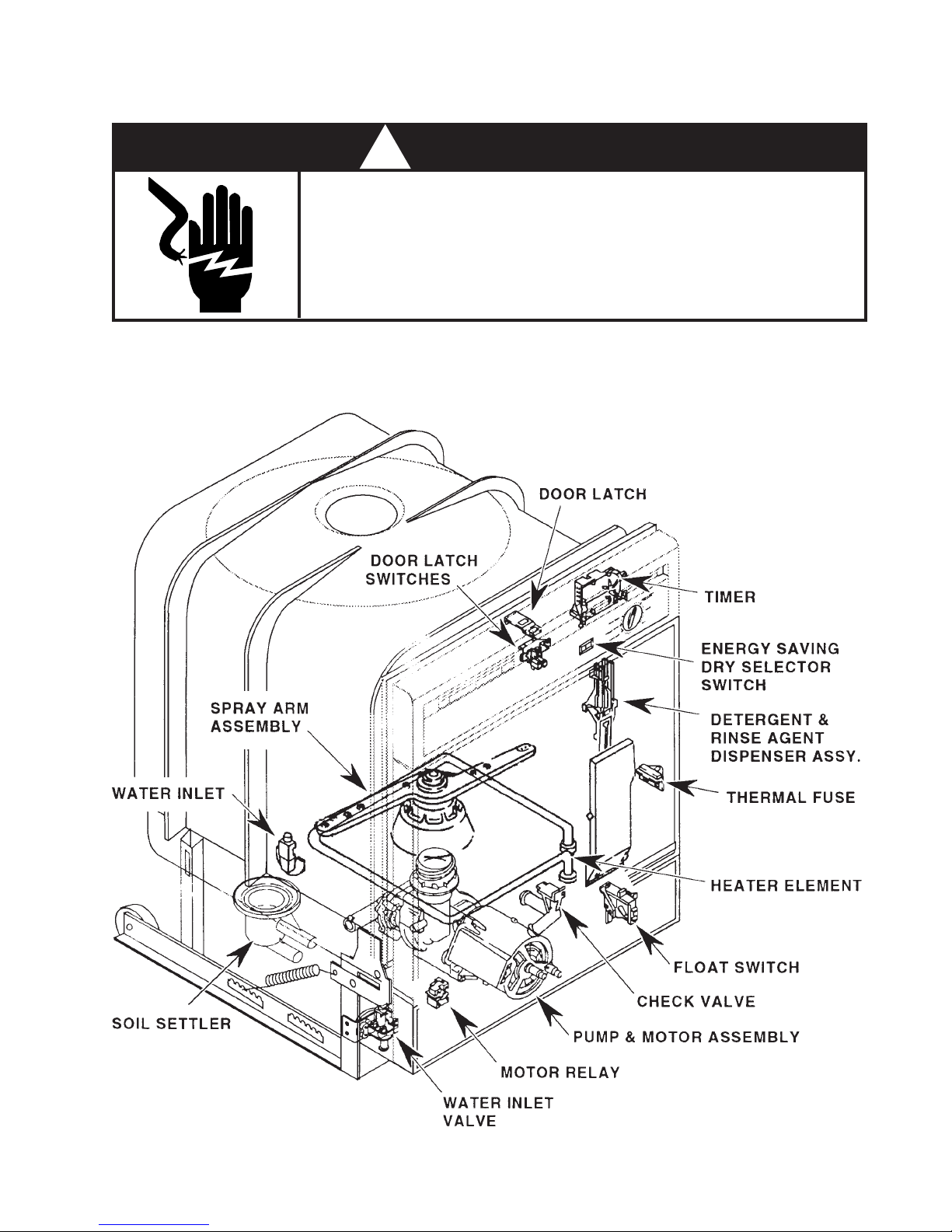
COMPONENT ACCESS
! WARNING
ELECTRICAL SHOCK HAZARD
Disconnect electric supply from the dishwasher before servicing.
Replace all panels before operating.
Failure to do so could result in death or electrical shock.
Component Location
(Bottom Right-side
Rear of Tub)
3
Removing the Spray Arm Assembly
1. Disconnect the dishwasher from the household electrical system.
2. Open the dishwasher door and remove the
lower rack.
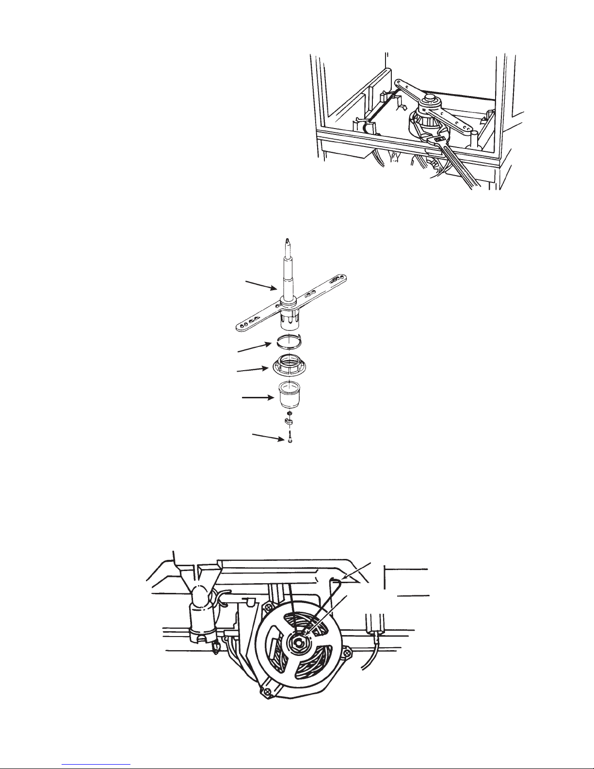
3. Use an adjustable slip-nut wrench and loosen
the pump outlet nut. (Fig. 1-4)
4. Lift the spray arm assembly out of the pump fitting.
Fig. 1-4
5. The spray arm can be disassembled by removing
the retaining screw from the spray arm and removing the split-ring seal, the pump outlet nut
and the support and bearing assembly. (Fig. 1-5)
SPRA Y ARM ASSEMBLY
SPLIT RING SEAL
PUMP OUTLET NUT
SUPPORT & BEARING
RET AINING SCREW
Fig. 1-5
Removing the Pump and Motor Assembly
1. Disconnect the dishwasher from the household electrical system.
2. Lay the dishwasher on its back and disconnect the wiring harness connector from the motor.
3. Remove the motor support slip nut and remove the motor support.
MOTOR SUPPORT
SUPPORT
SPLIT NUT
Fig. 1-6
4
(Fig. 1-6)
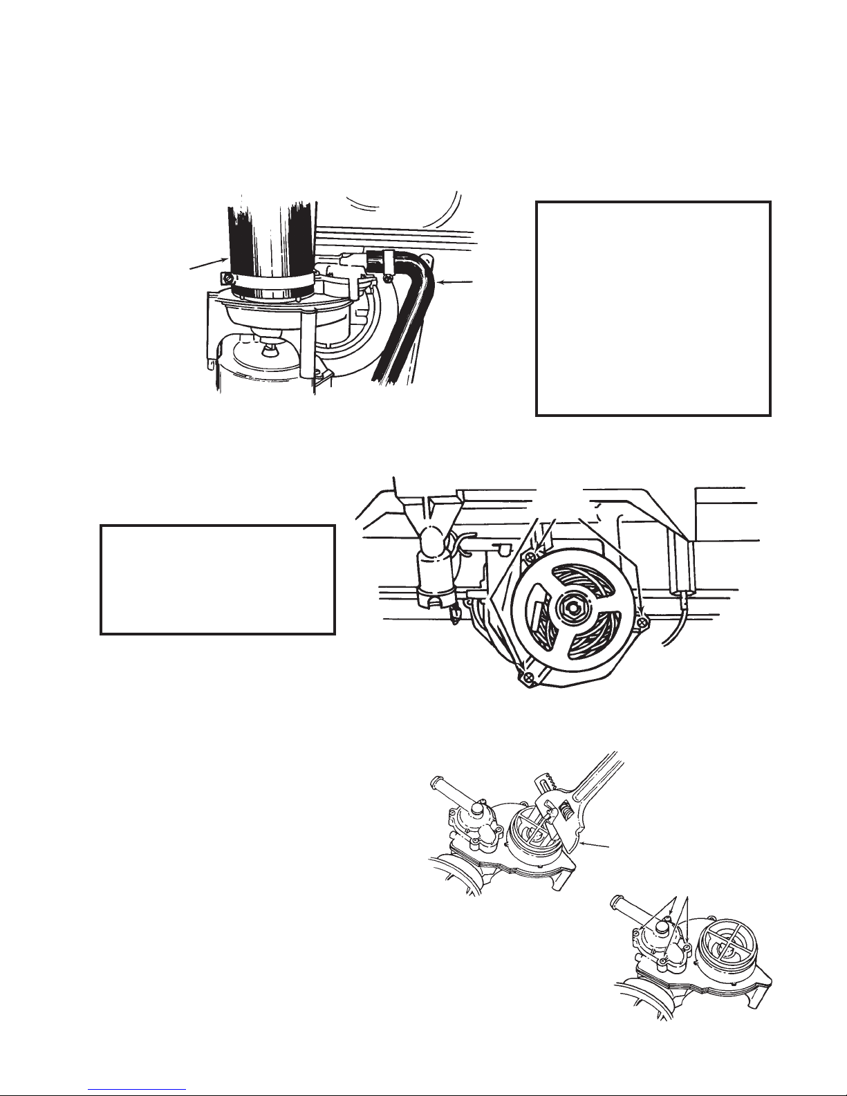
4. Disconnect the drain hose from the drain valve by loosening the Hex-head screw on the hose
clamp. (Fig. 1-7)
5. Disconnect the pump inlet hose from the pump and motor assembly. (Fig. 1-7)
6. Remove the pump and motor assembly from the bottom of the dishwasher.
NOTE:Once the pump and mo-
tor assembly has been
PUMP INLET
HOSE
DRAIN
HOSE
removed from the tub,
the pump outlet grommet can be removed
from the inside of the
tub. Check the pump
outlet grommet for wear
or damage and replace
it if necessary.
Fig. 1-7
The motor can be removed from the pump assembly by removing the three T-20 Torx screws securing
the motor to the pump assembly.
(Fig. 1-8)
NOTE:When reinstalling the
motor make sure the
keyed motor shaft lines
up with the pump impeller.
Servicing the Pump Assembly
The pump impeller can be accessed by using
an adjustable slip-nut wrench to turn the
disk mount assembly counterclockwise.
Once the disk mount assembly is removed,
the impeller can be removed.
(Fig. 1-9)
SCREWS
Fig. 1-8
Fig. 1-9
TORX
SLIP-NUT WRENCH
TORX
SCREWS
The drain valve can be accessed by removing
the four (4) T-20 Torx screws securing the drain
outlet cover to the pump assembly. The drain
cover seal, diaphragm and diaphragm ring can
be removed and replaced.
(Fig. 1-10)
Fig. 1-10
5
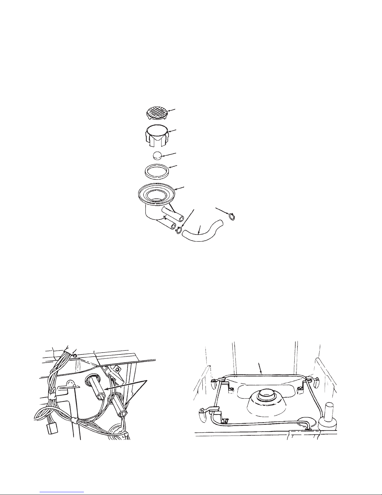
Removing the Soil Settler Assembly
1. Disconnect the dishwasher from the household electrical system and lay the unit on its back.
2. Remove the four (4) Hex-head screws securing the soil settler assembly to the tub.
3. Disconnect the two (2) hoses from the soil settler collector.
4. Remove the funnel and funnel grate, check valve ball and seal from the soil settler collector.
(Fig. 1-11)
FUNNEL GRA TE
FUNNEL
CHECK VAL VE BALL
SEAL
CLAMPS
HOSE
Fig. 1-11
Removing the Heater Element
1. Disconnect the dishwasher from the household electrical system.
2. Disconnect the wiring harness connectors from the heater element terminals with a pair of
needlenose pliers.
3. Remove the two long Hex-head nuts securing the heater element to the tub.
4. Remove the heater element from the three (3) metal clips that hold it suspended inside the tub.
(Fig. 1-13)
HEATER
ELEMENT
HEA TER
ELEMENT
RET AINING
NUTS
(Fig. 1-12)
Fig. 1-12 Fig. 1-13
6
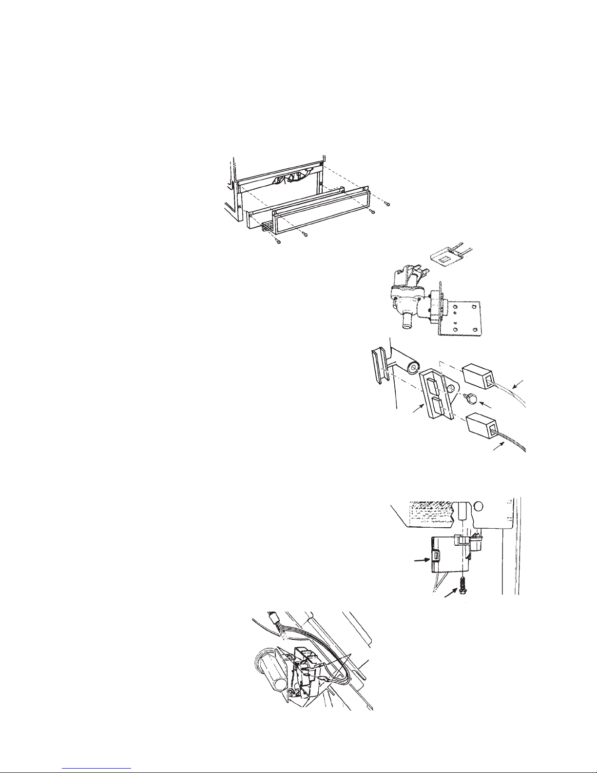
Removing the Water Inlet Valve
1. Turn off the water supply to the dishwasher.
2. Turn the timer knob clockwise to the NORMAL WASH position to energize the water inlet valve
and relieve water pressure in the line.
3. Turn the electrical supply to the dishwasher off and remove the toe panel and access panel.
(Fig. 1-14)
Fig. 1-14
4. Disconnect the wiring harness connector from the
water inlet valve terminals.
(Fig. 1-15)
5. Disconnect the water lines from the water inlet valve.
6. Remove the Hex-head screw securing the water inlet
valve to the tub support assembly.
Removing the Thermal Fuse
1. Turn the electrical supply to the dishwasher off and
remove the toe panel and access panel.
2. Disconnect the orange and white wires from the thermal
fuse terminals.
(Fig. 1-16)
3. Remove the Hex-head screw securing the thermal fuse
to the tub and remove the thermal fuse from the dishwasher.
Removing the Float Switch
1. Turn the electrical supply to the dishwasher off and
remove the toe panel and access panel.
2. Remove the Hex-head screw securing the float switch
to the tub.
3. Lift the float from the housing inside the tub.
4. Unsnap the float switch housing cover and disconnect
the two (2) wires from the terminals of the switch.
(Fig. 1-18)
(Fig. 1-17)
THERMAL
FUSE
FLOAT
SWITCH
HOUSING
RETAINING
SCREW
Fig. 1-15
Fig. 1-16
WHITE
WIRE
RET AINING
SCREW
ORANGE
WIRE
Fig. 1-17
Fig. 1-18
TERMINALS
WIRES
SWITCH COVER
7
Removing the Check V alve
1. Remove the toe panel and access panel from the
bottom of the dishwasher.
RETAINING
SCREW
2. Remove the hoses from the check valve.
Fig. 1-19
3. Remove the Hex-head screw securing the check valve to
the tub support.
(Fig. 1-19)
Removing the Motor Relay
1. Disconnect the dishwasher from the electrical supply and remove
the toe panel and access panel from the bottom of the dishwasher.
2. Disconnect the three (3) wiring harness connectors from the motor relay terminals.
3. Remove the Hex-head screw securing the motor relay to the tub support.
RET AINING
SCREW
(Fig. 1-20)
Accessing Components Inside the Door
1. Disconnect the dishwasher from the electrical
supply and remove the toe panel and access
panel from the bottom of the dishwasher.
2. Disconnect the end of the door springs
from the door spring tension adjustment
holes in the frame runner. Note which
holes were used and reattach the door
springs in the same holes when the repairs
are complete.
3. Open the dishwasher door and remove the
eight (8) T-15 Torx screws securing the inner
door panel from the door frame.
4. Remove the timer cover by releasing the
two (2) retaining tabs at each end from the
door frame.
(Fig. 1-21)
(Fig. 1-22)
Fig. 1-20
Fig. 1-21
T-15
TORX
Fig. 1-22
8
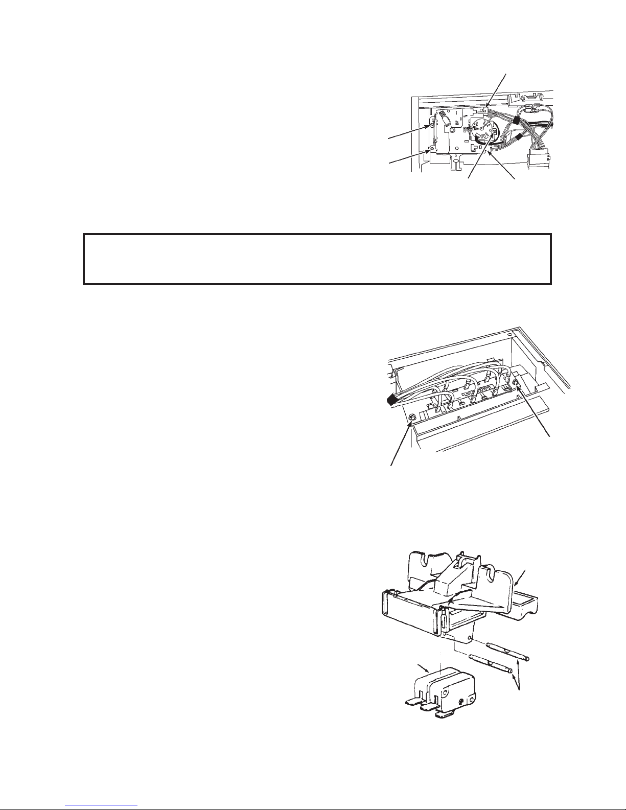
Removing the Timer
1. Disconnect the dishwasher from the electrical
supply and remove the toe panel and access
panel from the bottom of the dishwasher and
the inner door panel.
Screw
2. Disconnect the wiring harness connectors from
the timer terminals.
(Fig. 1-23)
3. Remove the three (3) Hex-head screws securing
the timer to the door frame.
(Fig. 1-23)
The timer,
Screw
Screw
Fig. 1-23
cam and cam follower can now be removed.
NOTE:When reinstalling the cam, be sure it is aligned with the keyed shaft of the timer.
When reinstalling the timer, be sure the cam follower post is positioned inside the
cam’s groove.
Removing the Switch Assembly
1. Disconnect the dishwasher from the electrical
supply and remove the toe panel and access
panel from the bottom of the dishwasher and
the inner door panel.
Wiring Harness
Connector
Wiring
Harness
Connector
2. Disconnect the harness wires from the spade
connectors on the switch assembly.
(Fig. 1-24)
3 . Remove the two (2) Hex-head screws securing
the switch assembly to the door frame.
The switch assembly can now be removed.
(Fig. 1-24)
Screw
Fig. 1-24
Removing the Door Latch Switches
1. Disconnect the dishwasher from the electrical supply and remove the toe panel and access
panel from the bottom of the dishwasher and the inner door panel.
2. Disconnect the wiring harness connectors from
the door latch switch terminals.
3. Unclip the handle and latch assembly from the
door frame.
4. To remove the switches from the handle and latch
assembly, push the two (2) retaining pins out of the
holes and remove the switches.
SWITCHES
(Fig. 1-25)
HANDLE &
ASSEMBLY
Screw
LATCH
RETAINING
PINS
Fig. 1-25
9
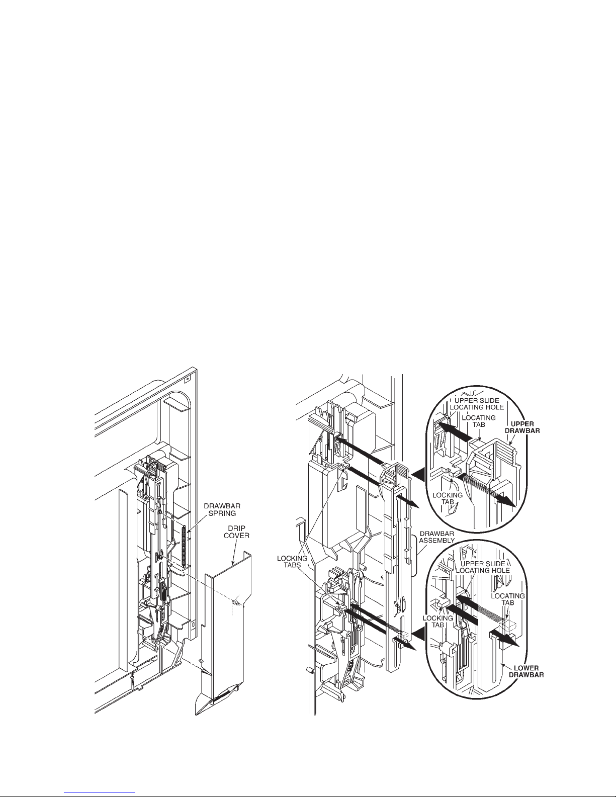
Dishwasher Dispenser Disassembly
1. Remove the drawbar spring.
(Fig. 1-26)
2. Align the lower drawbar holes with the locking tabs and remove the upper and lower drawbars.
As you do, note the locating tabs behind them and how they align with their respective locating
holes.
3. Slide the drawbars apart.
4. Turn the wet agent cap and seal assembly counterclockwise and remove it.
(Fig. 1-27)
(Fig. 1-28)
(Fig. 1-29)
5. Remove the seal from the cap.
6. Use Special Tool - Part No. 303918 or a ¾” socket to press over the attaching tabs
in the wet agent cap opening. Remove wet agent dispenser assembly.
7. Remove wet agent dispenser actuator by spreading the two (2) locking tabs.
(Fig. 1-30)
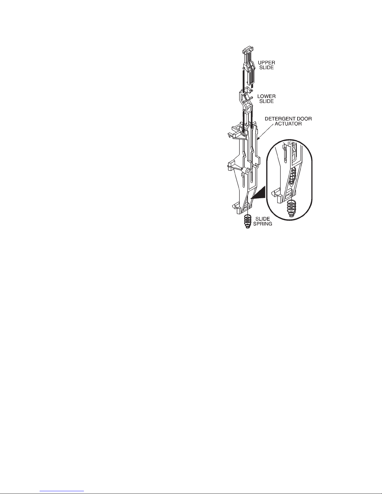
8. Remove the upper and lower slides from the wet agent dispenser actuator.
9. Remove the diaphragm spring and diaphragm.
10. Use a screwdriver to gently release the lower tab and remove the detergent door
actuator assembly. As you do, note the position of the door latch level through the hole in the
lower slide.
11. Remove the upper slide, the slide spring and the lower slide.
(Fig. 1-31)
(Fig. 1-32)
Fig. 1-26 Fig. 1-27
10
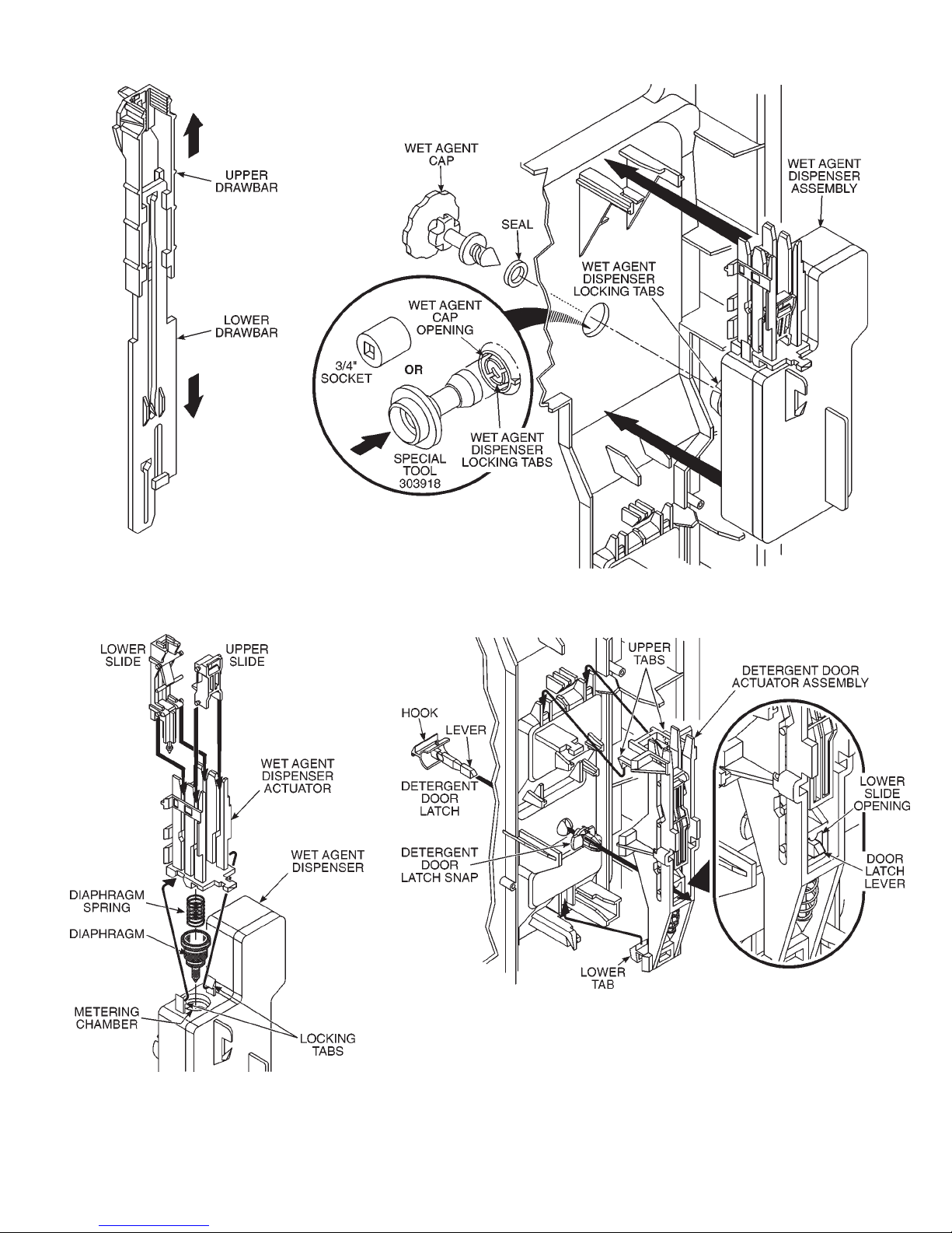
Fig. 1-28
Fig. 1-29
Fig. 1-30
Fig. 1-31
11
Dishwasher Dispenser Assembly
1. Assembly the upper slide, slide spring
and lower slide to the detergent
door actuator.
2. Pass the detergent door latch lever
through the panel making sure to turn the
hook of the latch toward the detergent
door. Snap the detergent door latch snap
onto the door latch lever.
3. The door latch lever must pass through
the opening in the lower slide. Press the
actuator assembly into position until the
upper and lower tabs engage.
4. Insert the diaphragm and diaphragm
spring into the wet agent dispenser . Seat
the diaphragm flush with the surface of
the dispenser.
5. Install the upper and lower slides into the
wet agent dispenser actuator.
6. Press the wet agent dispenser actuator
into position on the dispenser so the locking tabs engage.
(Fig. 1-32)
(Fig. 1-31)
(Fig. 1-30)
Fig. 1-32
7. Press the wet agent dispenser assembly
into position so the locking tabs engage
the wet agent cap opening. No tool is
needed for assembly.
(Fig. 1-29)
8. Install the seal on the wet agent cap.
9. Insert the wet agent cap. Turn it clockwise and close it.
10. Slide the upper and lower drawbars
together.
(Fig. 1-28)
11. Move all slides in both assemblies fully
down. Keep the drawbars slid fully together and align the drawbar holes over
the locking tabs. Look behind the draw
bars and make sure to engage the locating tabs with their respective locating
holes. Press the drawbars into position
and slide them upward behind the locking
tab ears.
12. Install the drawbar spring.
(Fig. 1-27)
(Fig. 1-26)
13. Install the drip cover by snapping it into
place.
12
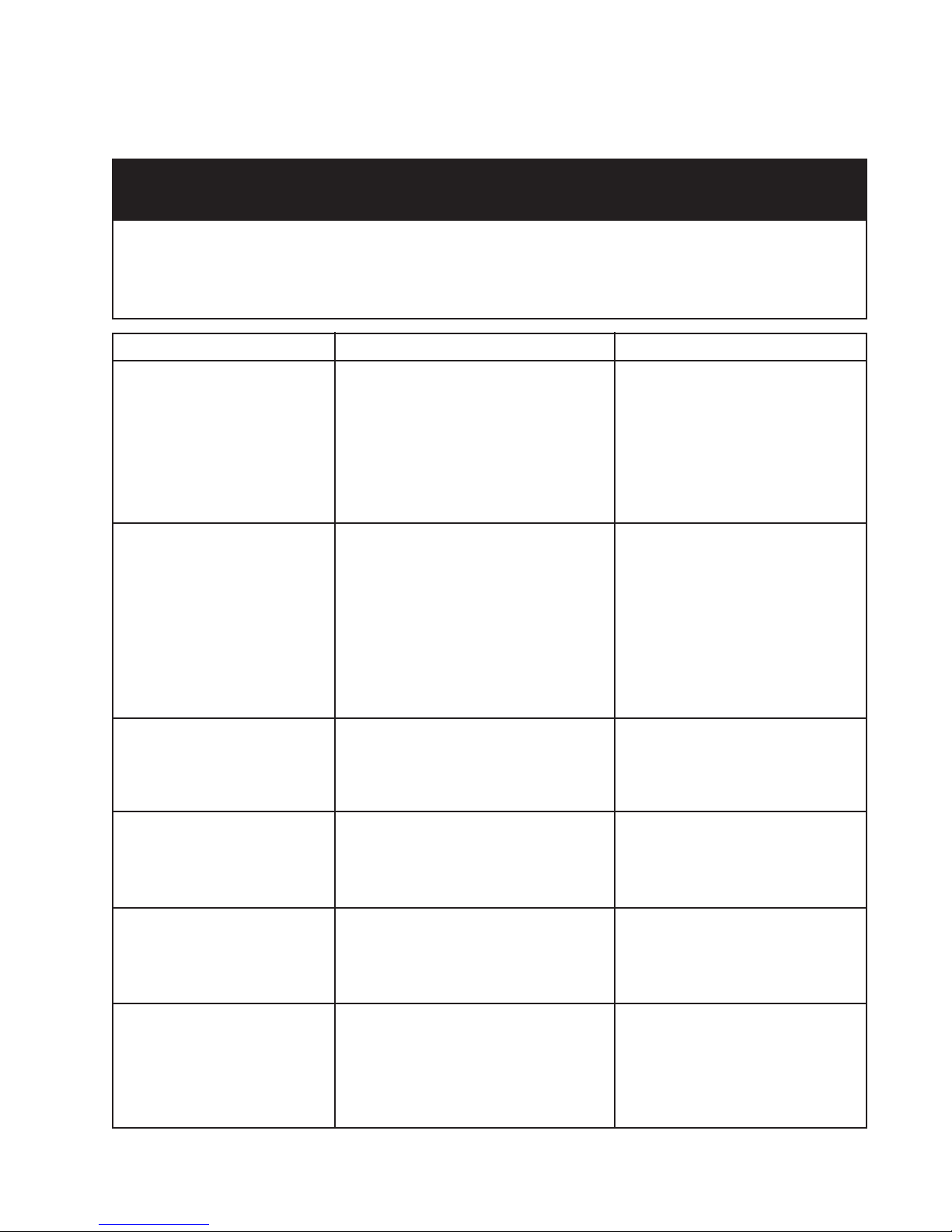
SOLUTIONS TO COMMON PROBLEMS
DIAGNOSING PROBLEM COMPONENTS
PRECAUTIONS TO BE OBSERVED WHILE DIAGNOSING
PROBLEM COMPONENTS
Disconnect electric power from the dishwasher.
Voltage checks should be made by inserting meter probes beside the wires in the connector blocks with the electric power source on
and the connector block plugged in.
Resistance checks should be made on components with the electric power off and the connector blocks disconnected.
COMPONENT SCHEMATI C TESTING PROCEDURE RESULTS
Motor Start Relay
1. Disconnect the wire connectors and
remove relay from unit.
2. Set VOM meter on the Rx1 scale.
3. Set the relay upright.
4. Measure resistance between blue and
violet contacts.
5. Turn relay upside-down.
6. Measure resistance between blue and
violet contacts.
1. Relay upright - meter should read
º (infinity.)
2. Relay upside-down - meter should
read less than two (2)Ω.
Drive Motor
Thermal Fuse
Heater Element
Fill Valve
1. Disconnect the motor wiring harness
plug from the motor connector.
2. Set VOM meter on the Rx1 scale.
3. Connect one probe to the white/violet
connector.
4. Connect the other probe to the blue/
white connector.
5. Connect the meter probe to the yellow
connector.
6. Connect the probe to the grey
connector.
1. Disconnect wires connectors from the
thermal fuse terminals.
2. Set VOM meter to read Rx1 scale.
3. Measure resistance between thermal
fuse terminals.
1. Disconnect the wire connectors from
the heater element terminals.
2. Set VOM meter to read Rx1 scale.
3. Measure resistance between heater
element terminals.
1. Disconnect the wiring harness plug
from the fill valve connector.
2. Set VOM meter to read Rx1 scale.
3. Measure resistance between the
terminals of the fill valve.
1. White/violet to blue/white - meter
should read 5 - 7Ω.
2. White/violet to yellow - meter
should read 5 - 7Ω.
3. White/violet to gray - meter
should read 5 - 7Ω.
1. Meter should read 0Ω.
1. Meter should read 25 - 35Ω.
1. Meter should read approximately
700Ω.
Overfill Switch
1. Disconnect the wires connectors from
the overfill switch terminals.
2. Set VOM meter to read Rx1 scale.
3. Measure resistance between switch
terminals.
4. Block the float in the UP (full) position
and measure resistance again.
13
1. Float DOWN - meter should read
0Ω.
2. Float UP - meter should read
º (infinity).

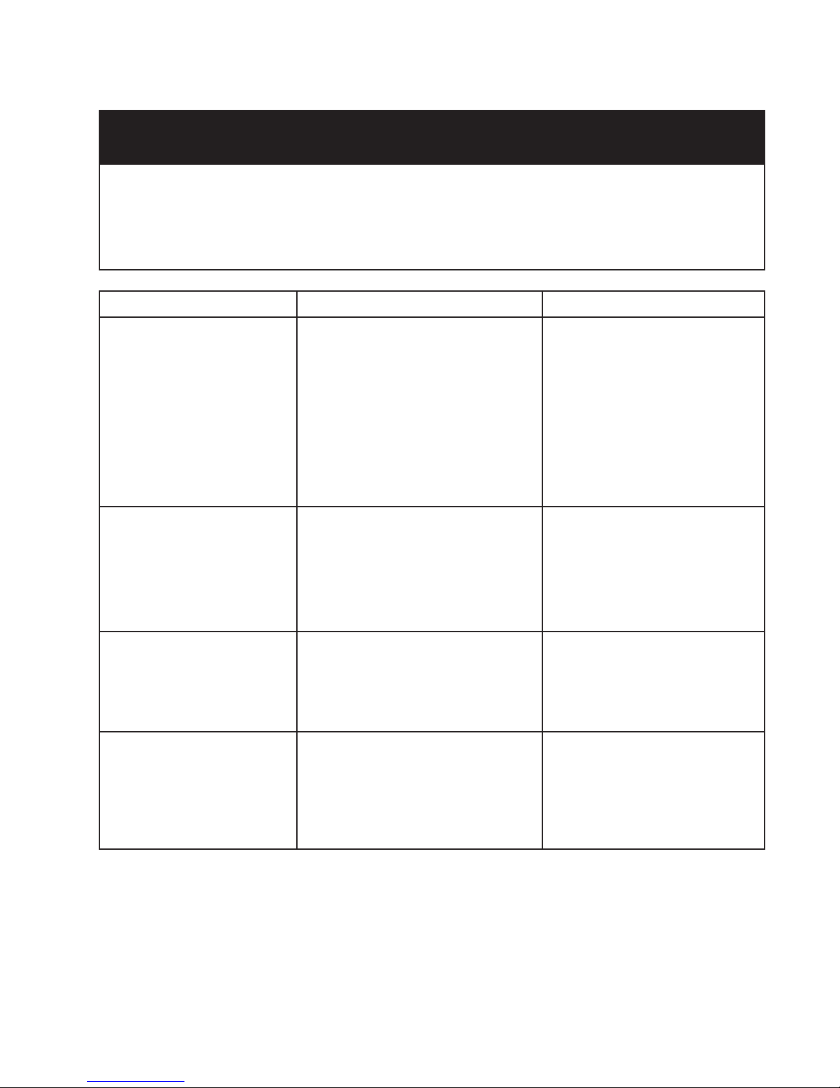
COMPONENT SCHEMATIC TESTING PROCEDURE RESULTS
Timer Motor
1. Disconnect the Wiring harness
connector from the timer assembly.
2. Set VOM meter on the Rx1 scale.
3. Measure resistance between timer
motor terminals.
1. Meter should read 1800 - 3000Ω.
Timer
Dispenser Mechanism
1. Disconnect the wiring harness
connector from the timer assembly.
2. Set VOM meter on the Rx1 scale.
3. Connect one probe to contact 31.
(Tan)
4. Connect the other probe to the timer
contact to be tested.
5. Manually advance the timer until the
contact closes.
6. Manually advance the timer until the
contact opens.
1. Remove the front door panel.
2. Remove the drip cover.
3. Latch the detergent door closed.
4. Manually advance the timer through a
complete cycle slowly.
1. Contact CLOSED - meter should
read 0Ω.
2. Contact OPEN - meter should
read º (infinity).
1. At 12 o’clock position - Draw bars
will move upward causing the
detergent actuator assembly to
release the latch and detergent
cup should open.
2. At 4 o’clock position - Draw bars
will again move upward causing
the wetting agent actuator to
release wetting agent.
3. From the 6 o’clock position to the
8 o’clock position the draw bars
are driven down to reset the
mechanism.
14
TROUBLESHOOTING GUIDE
PRECAUTIONS TO BE OBSER VED WHILE TROUBLESHOOTING
AND DIAGNOSING PROBLEMS
Always check wiring harness and connectors before initiating any test procedures.
Disconnect electric power from the dishwasher before touching the printed circuit boards or re-seating wire connectors.
Voltage checks should be made by inserting meter probes beside the wires in the connector blocks with the electric power source on
and the connector block plugged in.
Resistance checks should be made on components with the electric power off and the connector blocks disconnected.
PROBLEM POSSIBLE CAUSES CORRECTION/TEST
Dishwasher does not run or
stops during a cycle
Dishwasher will not fill
Dishwasher will not drain
1. Door is not latching properly.
2. Child lock is "ON".
3. Wash Cycle not set properly.
4. Household fuse blown or circuit
breaker tripped.
5. Washer is not wired into a circuit with
proper voltage.
1. Overflow protection float is stuck in
"up" position.
2. Fill valve is inoperable.
3. Open timer contacts.
1. Air gap (if installed) is clogged.
2. Pump motor is inoperable.
3. Open timer contacts.
1. Check to make sure handle link
is properly seated in door latch
assembly. Check that the door
switch is opening and closing
properly.
2. Turn child lock "OFF"
3. Review setting Wash Cycles in
the Use and Care Guide.
4. Have a qualified electrician check
the circuit breaker or fuse.
5. Have customer call a qualified
electrician.
1. Check that the overflow
protection float is free to move
"up" and "down". Check that the
overfill switch in opening and
closing properly.
2. Check for continuity between
contacts on fill valve.
3. Test timer contacts.
1. Follow air gap manufacturer's
direction for cleaning.
2. Disconnect pump motor from
wiring harness and check for
continuity.
3. Test timer contacts.
Dishwasher will not
dry dishes
1. Heater element burned out.
2. Hi-limit thermostat inoperable.
3. Open circuit between timer and
heater.
15
1. Check for continuity between the
terminals of the heater element.
2. Check for continuity between
terminals of the hi-limit
thermostat.
3. Check for continuity between
timer switch contacts and heater.
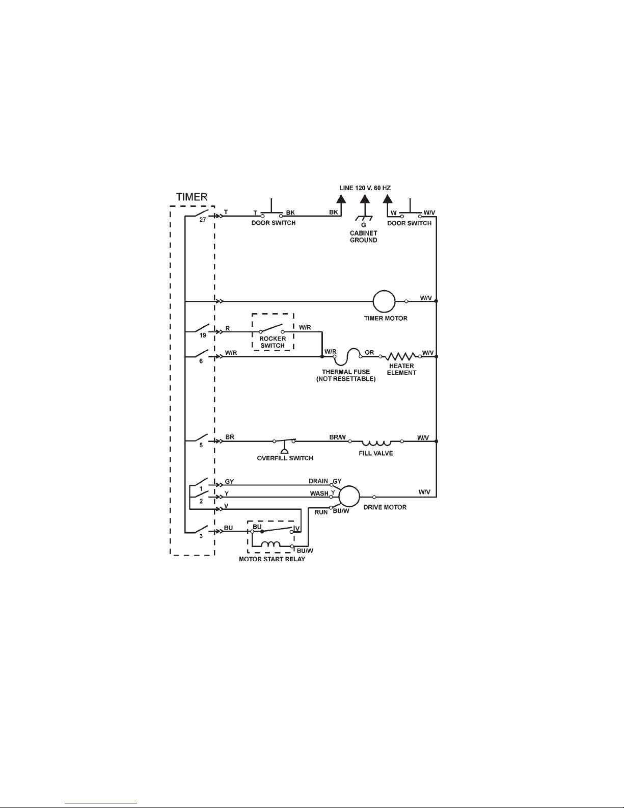
Wiring Diagram
Models DU800DWG, DU801DWG, DU805DWG
TECHNICAL INFORMA TION
SCHEMATIC SHOWN WITH DOOR SWITCHES CLOSED,
ALL CONT ACTS OPEN
16
 Loading...