


APARTMENT MAINTENANCE SERIES
CONSUMER SERVICES TECHNICAL
EDUCATION GROUP PRESENTS
APARTMENT MAINTENANCE SERIES
LAUNDRY
PRODUCTS
AM-5
JOB AID
Part No. 4322616
I

INTRODUCTION
This Job Aid,
specific information for the installation, service and repair of Whirlpool Laundry products.
“AM-5, Apartment Maintenance Series- Laundry Products,”
recent information on design, features, troubleshooting, service and repair procedures.
“AM-5, Apartment Maintenance Series- Laundry Products,”
has been compiled to provide the most
(Part No. 4322616) provides
GOALS AND OBJECTIVES
The goal of this Job Aid is to provide detailed information that will enable the service technician to
properly diagnose malfunctions and repair Whirlpool Laundry Products.
The objectives of the Job Aid are:
The service technician will -
• Understand proper safety precautions.
• Successfully troubleshoot and diagnose malfunctions.
• Successfully perform necessary repairs.
• Successfully return the laundry product to proper operational status.
CORPORATION
WHIRLPOOL CORPORATION ASSUMES NO RESPONSIBILITY
FOR ANY REPAIRS MADE ON OUR PRODUCTS BY ANYONE
OTHER THAN AUTHORIZED SERVICE TECHNICIANS.
© 1999 Whirlpool Corporation, Benton Harbor, MI 49022
II

TABLE OF CONTENTS
INTRODUCTION .................................................................................. II
TABLE OF CONTENTS...................................................................... III
SAFETY ............................................................................................ VIII
SECTION ONE - DIRECT DRIVE WASHER
Part A
INSTALLATION CONSIDERATIONS .......................................2
Part B
THEORY OF OPERATIONTHEORY OF OPERATION
THEORY OF OPERATION
THEORY OF OPERATIONTHEORY OF OPERATION
Fill.................................................................................................................... 5
Agitation........................................................................................................... 8
Drain.............................................................................................................. 10
Spin ............................................................................................................... 12
............................................................................................................
......................................................
............................................................................................................
55
5
55
Part C
COMPONENT ACCESSCOMPONENT ACCESS
COMPONENT ACCESS
COMPONENT ACCESSCOMPONENT ACCESS
Component Location...................................................................................... 15
Accessing Component in the Console............................................................ 16
Accessing Component inside the Washer Cabinet......................................... 19
....................................................................................................................................
..................................................................
....................................................................................................................................
1515
15
1515
Part D
DIAGNOSIS AND TROUBLESHOOTINGDIAGNOSIS AND TROUBLESHOOTING
DIAGNOSIS AND TROUBLESHOOTING
DIAGNOSIS AND TROUBLESHOOTINGDIAGNOSIS AND TROUBLESHOOTING
Diagnosis and Troubleshooting Chart............................................................ 25
Component T esting........................................................................................ 27
Wiring Diagram .............................................................................................. 32
Cycle Chart.................................................................................................... 33
Model/Serial Number Designators ................................................................. 34
Reshipping Kit and Instructions........................................................................35
............................................................
..............................
............................................................
2525
25
2525
III

SECTION TWO - 22” COMPACT WASHER
Part A
THEORY OF OPERATIONTHEORY OF OPERATION
THEORY OF OPERATION
THEORY OF OPERATIONTHEORY OF OPERATION
General Information ....................................................................................... 39
Cycle Functions ............................................................................................. 42
........................................................................................................
....................................................
........................................................................................................
3939
39
3939
Part B
COMPONENT ACCESSCOMPONENT ACCESS
COMPONENT ACCESS
COMPONENT ACCESSCOMPONENT ACCESS
Washer T op Components .............................................................................. 45
Cabinet Components ..................................................................................... 49
....................................................................................................................................
..................................................................
....................................................................................................................................
4545
45
4545
Part C
TROUBLESHOOTING AND DIAGNOSISTROUBLESHOOTING AND DIAGNOSIS
TROUBLESHOOTING AND DIAGNOSIS
TROUBLESHOOTING AND DIAGNOSISTROUBLESHOOTING AND DIAGNOSIS
Troubleshooting Chart ................................................................................... 59
Diagnostic T est Program................................................................................ 61
............................................................
..............................
............................................................
5959
59
5959
Part D
TECH TIPSTECH TIPS
TECH TIPS
TECH TIPSTECH TIPS
Wiring Diagram .............................................................................................. 65
Control Sequence Chart ................................................................................ 66
Strip Circuits .................................................................................................. 67
....................................................................................................................................................
..........................................................................
....................................................................................................................................................
6565
65
6565
IV

SECTION THREE - 29” AND COMPACT
GAS AND ELECTRIC DRYERS
Part A
THEORY OF OPERATION ....................................................71
Part B
COMPONENT ACCESSCOMPONENT ACCESS
COMPONENT ACCESS
COMPONENT ACCESSCOMPONENT ACCESS
................................................................................................................
........................................................
................................................................................................................
7373
73
7373
V

SECTION FOUR - 27” GAS AND ELECTRIC
DRYERS
Part A
THEORY OF OPERATION .................................................... 81
Part B
COMPONENT ACCESSCOMPONENT ACCESS
COMPONENT ACCESS
COMPONENT ACCESSCOMPONENT ACCESS
................................................................................................................
........................................................
................................................................................................................
8585
85
8585
Part C
TROUBLESHOOTING AND DIAGNOSISTROUBLESHOOTING AND DIAGNOSIS
TROUBLESHOOTING AND DIAGNOSIS
TROUBLESHOOTING AND DIAGNOSISTROUBLESHOOTING AND DIAGNOSIS
Troubleshooting Guide .................................................................................. 95
“C” Version Electronic Dryer Control.............................................................. 96
..................................................................................
.........................................
..................................................................................
9595
95
9595
Part D
TECH TIPSTECH TIPS
TECH TIPS
TECH TIPSTECH TIPS
Wiring Diagram .............................................................................................. 97
Timer Schedule.............................................................................................. 99
Strip Circuits .................................................................................................. 99
Model/Serial Number Plate Location............................................................ 102
Model/Serial Number Designators ............................................................... 102
....................................................................................................................................................
..........................................................................
....................................................................................................................................................
9797
97
9797
VI

SECTION FIVE - 24” and 27” THIN TWIN
Part A
THEORY OF OPERATION ................................................. 105
Part B
COMPONENT ACCESS (24)COMPONENT ACCESS (24)
COMPONENT ACCESS (24)
COMPONENT ACCESS (24)COMPONENT ACCESS (24)
Washer Access............................................................................................ 107
Dryer Access ............................................................................................... 109
COMPONENT ACCESS (27)COMPONENT ACCESS (27)
COMPONENT ACCESS (27)
COMPONENT ACCESS (27)COMPONENT ACCESS (27)
Washer Access.............................................................................................11 1
Dryer Access ............................................................................................... 11 3
......................................................................................
...........................................
......................................................................................
......................................................................................
...........................................
......................................................................................
107107
107
107107
111111
111
111111
Part C
TECH TIPSTECH TIPS
TECH TIPS
TECH TIPSTECH TIPS
Timer Schedules.......................................................................................... 1 1 9
Wiring Diagrams .......................................................................................... 120
Model/Serial Number Plate Location............................................................ 122
Model/Serial Number Designators ............................................................... 122
..................................................................................................................................................................
.................................................................................
..................................................................................................................................................................
119119
119
119119
VII
SAFETY
YOUR SAFETY AND THE SAFETY OF OTHERS IS IMPORTANT
Safety messages have been provided in this manual where performing certain procedures may
cause exposure to hazards that can kill or hurt you.
This is the safety alert symbol. All safety messages will be preceded by the safety
alert symbol and the word “DANGER” or “WARNING”.
!
These words mean:
! DANGER
YOU WILL BE KILLED OR SERIOUSLY INJURED
IF YOU DON’T FOLLOW INSTRUCTIONS.
! WARNING
YOU CAN BE KILLED OR SERIOUSLY INJURED
IF YOU DON’T FOLLOW INSTRUCTIONS.
All safety messages will identify the hazard, tell you how to reduce the chance of injury, and tell
you what can happen if the instructions are not followed.
VIII

DIRECTDIRECT
DIRECT
DIRECTDIRECT
DRIVEDRIVE
DRIVE
DRIVEDRIVE
WASHERSWASHERS
WASHERS
WASHERSWASHERS
1
Section One - Part A
INSTALLATION CONSIDERATIONS
1. Carefully follow the installation instructions supplied with the washer for information related to
your product.
KEY POINTS TO REMEMBER:
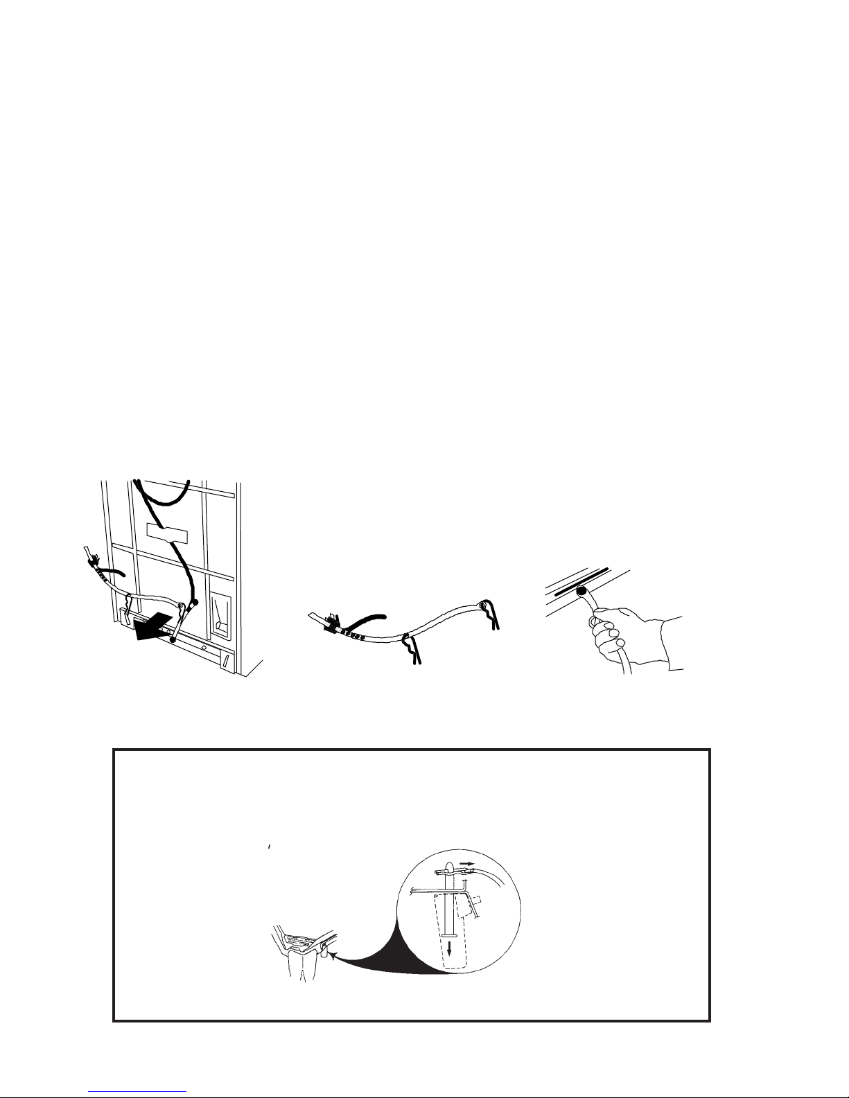
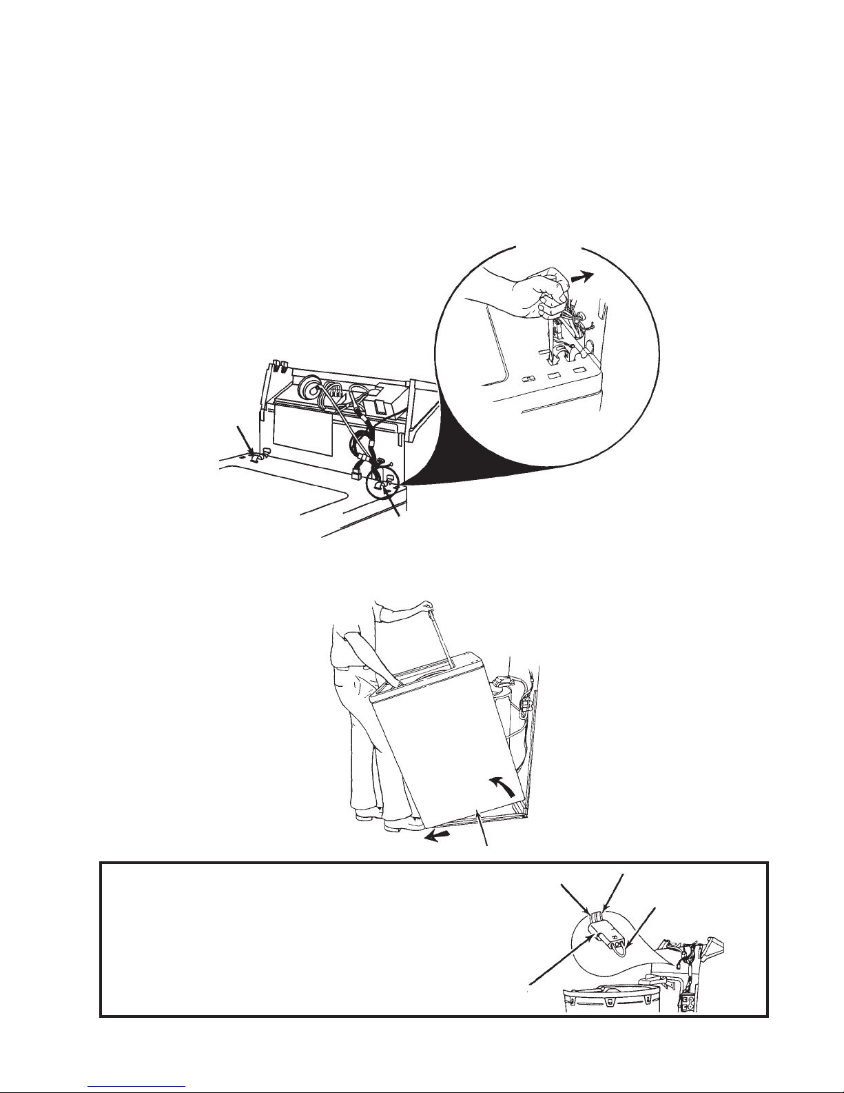
2. Remove the shipping strap as follows:
a. Carefully read, then remove the yellow label securing the power supply cord to the back of
the washer .
b. With the washer upright, pull the yellow shipping strap completely out of the back of the
washer. Be sure both cotter pins come out of the washer. Note that the power supply cord
plug will still be attached to the yellow shipping strap.
c. Firmly pull on the end of the yellow shipping strap that is attached to the bottom of the back
of the washer.
(Fig. 1-1)
(Fig. 1-3)
(Fig. 1-2)
This will release the self-leveling leg mechanism.
Fig. 1-2
Fig. 1-1
NOTE:To prevent the two (2) shipping pins from falling on the floor, two (2) plastic
holders are attached to the base.
the shipping pins fall into these holders. These pins may be left in the
holder cups.
washer.
(Fig. 1-4, INSET)
Fig. 1-4
(Fig. 1-4)
They will not interfere with the operation of the
When the cotter pins are removed,
Fig. 1-3
2
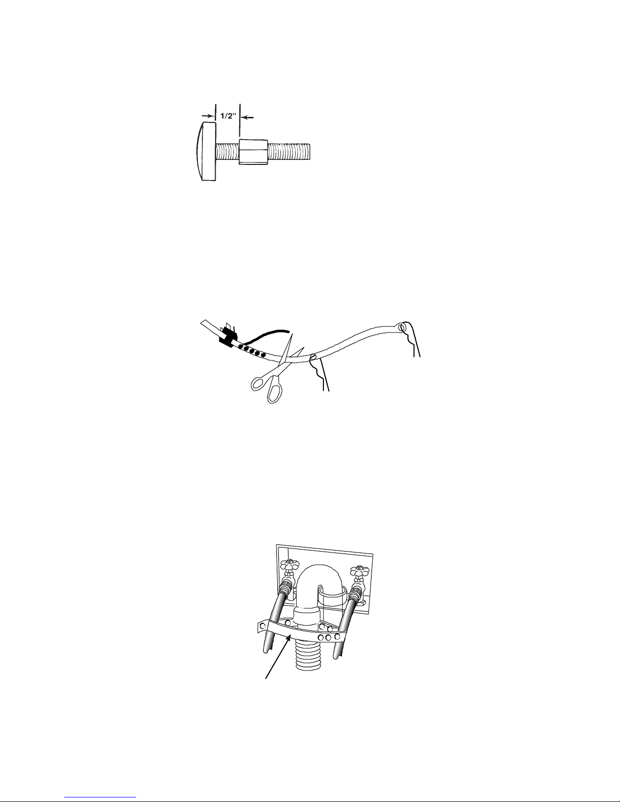
3. Screw the lock nut down to within 1/2 inch of the base of the leg.
Fig. 1-5
4. Tilt the washer forward off the floor and set back down to adjust the rear self-leveling legs.
5. Check the washer for level, both side-to-side and front-to-back. Adjust the front legs as
necessary. Tighten the locking nuts to the base of the washer with a wrench. If the nuts
are not tightened, the washer may vibrate excessively .
6. Cut the shipping strap at the words “CUT HERE” and slide it off the power supply plug.
(Fig. 1-6)
(Fig. 1-5)
Fig. 1-6
7. The hook-end of the drain hose can be installed into a stand pipe
tub,
(Fig. 1-7, C)
A
and secured with the shipping strap as shown.
B
STRAP
Fig. 1-7
C
(Fig. 1-7, A&B)
or laundry
STRAP
3

NOTE:
Laundry Drain Requirements:
Laundry Tub or Utility Sink -
1. Laundry tub or utility sink should have a minimum capacity of 20 gallons.
2. Top of tub or sink must be a minimum of 34” and not more than 72” from the
bottom of the washer.
Floor Drain -
1. Floor drain systems require a Siphon Break (Part No. 285320.) Siphon Break
must be above the high water level in the washer tub (a minimum of 28”
from the bottom of the washer.)
2. Additional drain hose will be required for a Floor Drain installation.
Standpipe Drain -
1. A minimum 2” diameter drain pipe with a minimum carry-away capacity of
17 gallons per minute is required.
2. Top of standpipe must be a minimum of 39” and not more than 72” from the
bottom of the washer.
COMMON INST ALLATION PROBLEMS
1. Water does not pump out.
Causes: a. Drain hose too high (over six feet).
b. Blockage or crimp in the drain hose.
c. Drain pipe not vented.
2. Water on the floor.
Causes: a. A leaking hose on the water inlet valve or faucet.
b. A leaking drain hose connection.
c. The drain hose is coming out of the stand pipe when draining.
d. Restricted drain pipe -- running beyond capacity.
3. The machine vibrates or “walks”.
Causes: a. Improperly installed front feet.
b. The washer is not level.
c. The shipping strap is not removed or a retaining pin is still attached to a
shipping pin on the base of the washer.
d. Floor not solid.
e. Rear leveling legs not set.
4. The machine doesn’t fill.
Causes: a. The water faucets are not turned on.
b. There is a blockage in the hose or the fill valves.
c. Drain hose siphoning -- too low or siphon break not installed.
4

Section One - Part B
THEORY OF OPERATION
All washers perform essentially the same four functions. They fill with water, agitate, drain the water
and spin the water out of the clothing.
FILL
Water Inlet
Water Level
Switch
Water
Temperature
Switch
Timer
Water Fill
Valve
Fig. 2-1
5
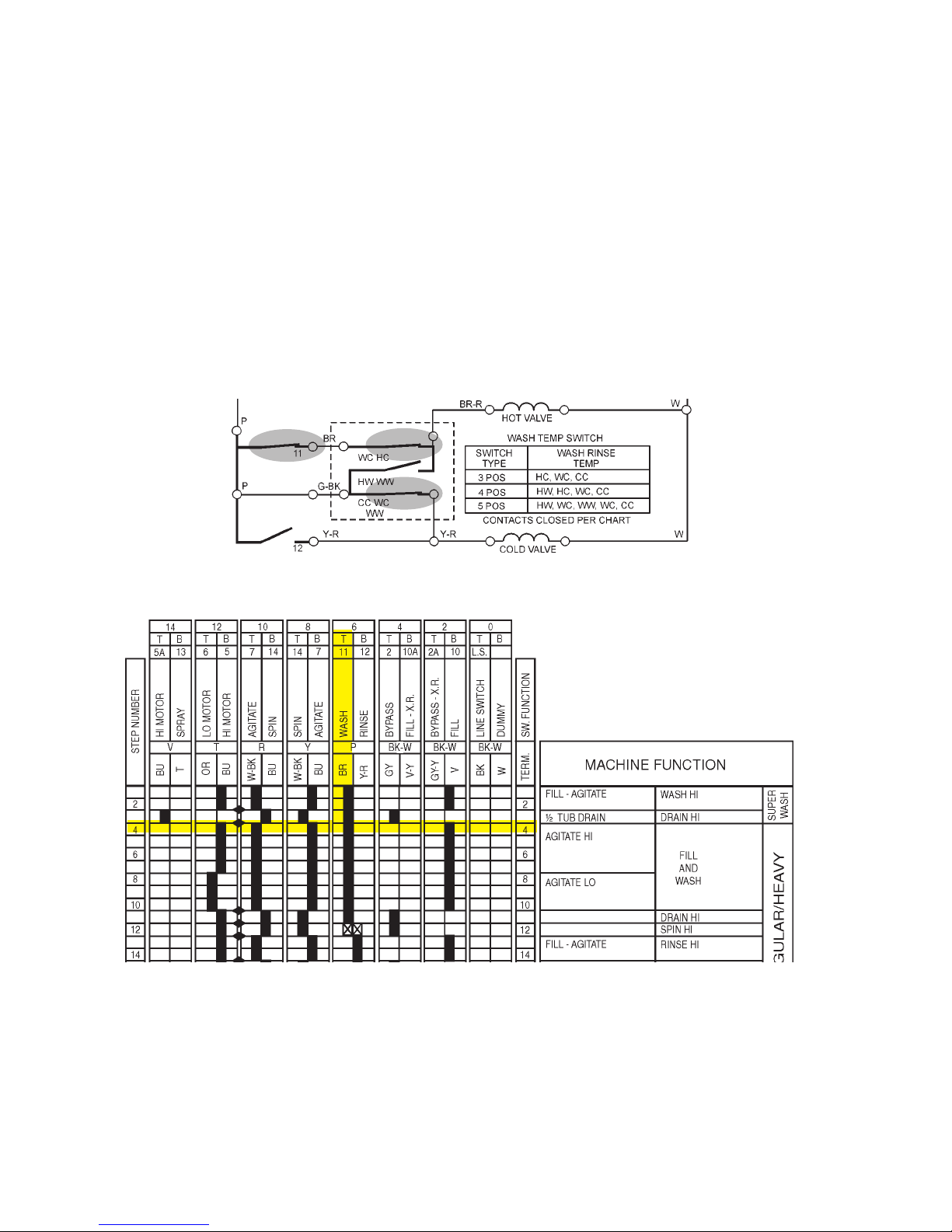
1. Before the washer can fill, the customer makes selections that:
• Control the length of the wash cycle by turning the timer control knob
• Control the temperature of the wash and rinse water by setting the water temperature switch.
The water temperature switch is identified by the dotted box in Fig. 2-2. The wash temp switch
chart indicates three possible switches, depending on the model washer being used. The switch
letters in the chart, H W and C are the possible water temperature selections, Hot , Warm and
Cold. The first letter is the wash temperature, the second letter is the rinse temperature.
• Control the amount of water required for the amount of clothing by setting the water level or
pressure switch.
2. Once the selections are made, a series of switches are closed in the timer and water temperature
switch. If, for example, the customer selects the beginning of the REGULAR cycle, increment 4,
and a WARM wash and COLD rinse, the following switches would be closed.
Fig. 2-2
Fig. 2-3
6
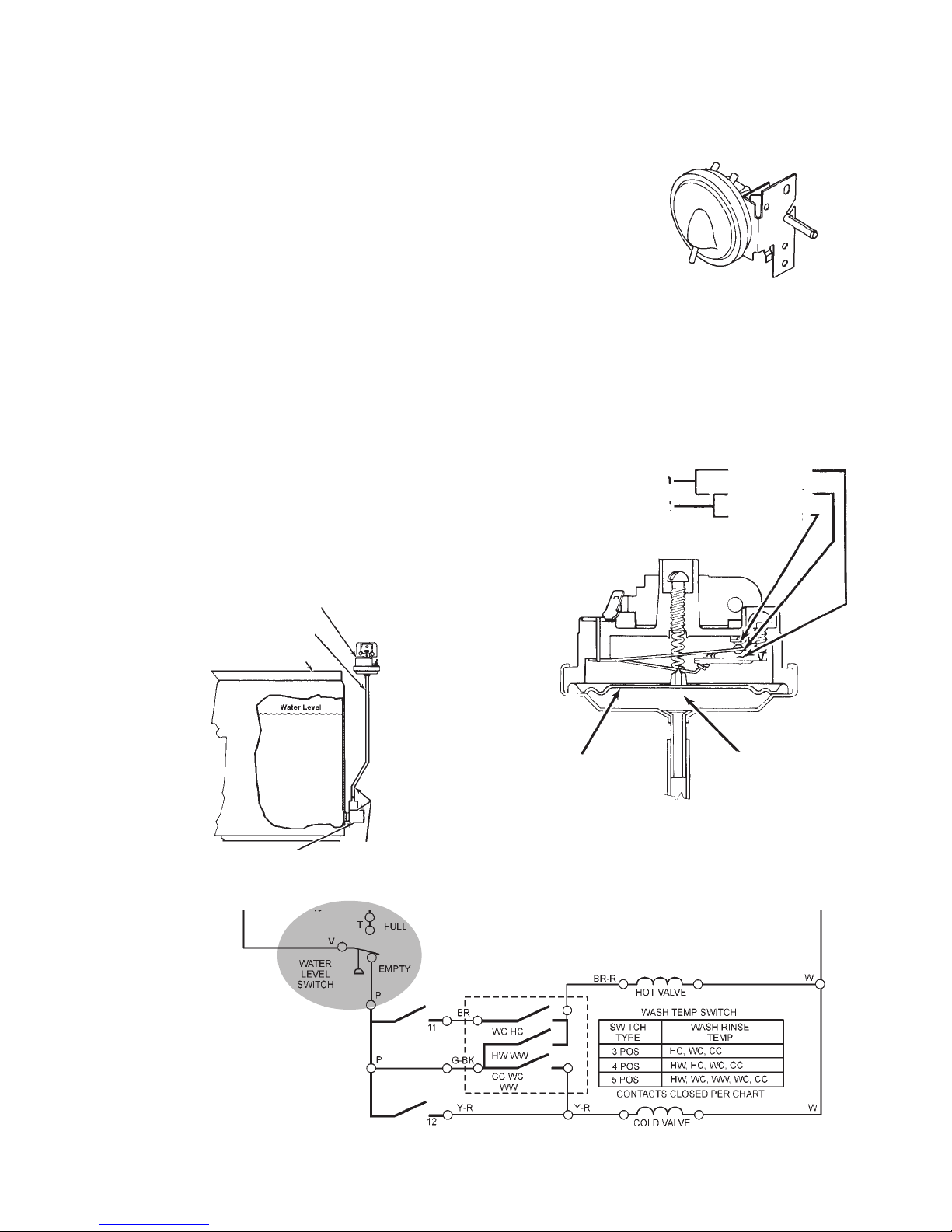
The water level switch is set to move from the
EMPTY position to the FULL position depending on how much tension is set on the switch
diaphragm.
3. When the customer pulls the timer knob out,
voltage is supplied to the hot and/or cold water inlet solenoids. In the example above, both
solenoids are energized to allow water to fill
the tub.
4. As the water level rises in the tub, it causes
an increase in air pressure in the air dome
assembly mounted to the side of the tub. A
hose between the air dome and the water level
switch transfers this air pressure against the
diaphragm in the water level switch, causing
electrical contacts to move from V to P ,
(EMPTY position), to V to T, (FULL position).
The washer stops filling and the water level
switch is providing voltage to the timer motor
and the drive motor to begin agitation.
Typical Water
Level Switch
Fig. 2-4
WATER LEVEL SWITCH
AT FULL POSITION
Open
Closed
P-Contact
V-Contact
T-Contact
Fig. 2-5
Water Level Switch
Hose
Tub
Air Dome
Assembly
Trapped Air In
Hose And Air
Dome Assembly
(Air Pressure)
Diaphragm
Air Pressure
Applied To
Diaphragm
Fig. 2-6
Fig. 2-7
7

Pump
AGITATION
Water Level
Switch
Timer
Drive
Motor
Gearcase
Fig. 2-8
8
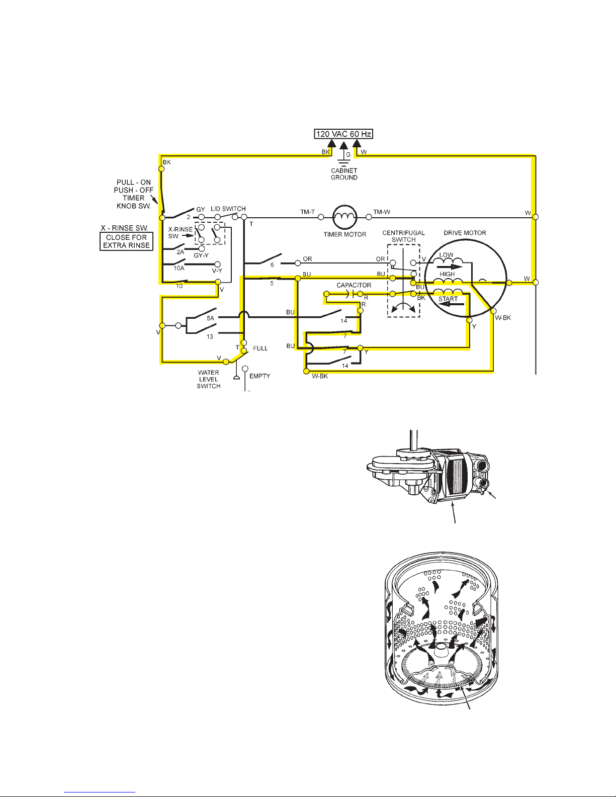
1. Once there is power to the timer motor, the timer will start to advance. The drive motor will also
begin to turn counterclockwise in the agitation direction. The direction of current through the dirve
motor start winding will determine the direction the drive motor runs. In the agitation mode, contacts 7 are closed, causing current to flow in the start winding opposite the flow in the run winding.
Fig. 2-9
2. The motor is coupled directly to the transmis-
sion and will cause the transmission shaft to
turn in the agitate direction. The agitator is
mounted directly to the transmission shaft and
is driven back and forth to provide agitation.
3. The water pump is mounted directly to the
motor and will also turn in the agitate direction. At this point the pump is running in reverse, so water does not leave the tub.
4. During the agitation cycle, the wash water is
being pulled through a basket mounted lint
filter, (if equpped), by pumping vanes molded
into the underside of the agitator. Due to the
shape of the filter, lint is captured on the filter
fins.
5. Also, during the agitation cycle, the transmis-
sion is being set up for neutral drain to provide a pump-out prior to going into spin.
Fig. 2-10
Pump
Motor
6. Once the timer has advanced to the end of
the wash cycle, contacts open in the timer
causing the drive motor to stop.
Lint Filter
Fig. 2-11
9

Pump
DRAIN
Water Level
Switch
Timer
Drive
Motor
Gearcase
Fig. 2-12
10
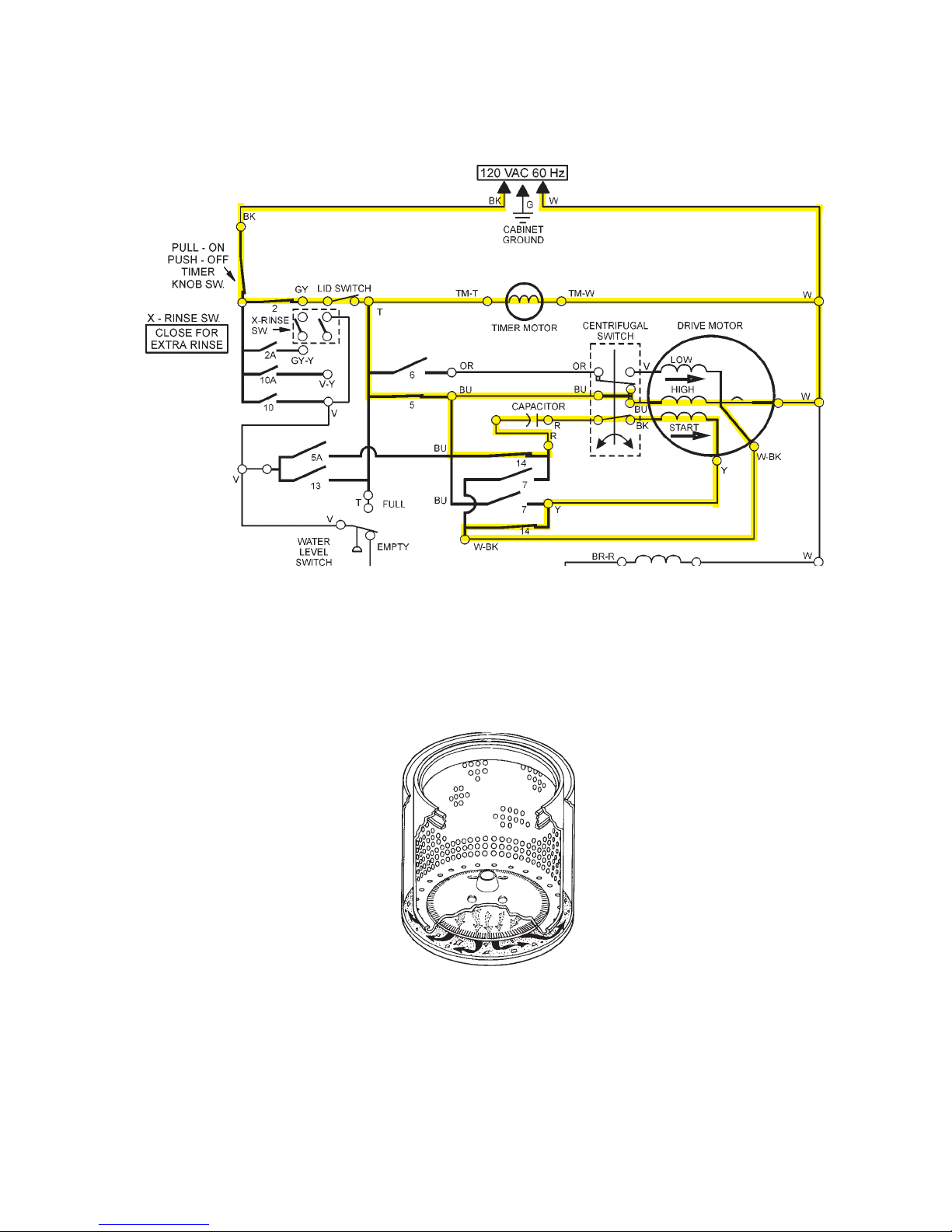
1. The timer advances to the next step in the process, which is the drain cycle. This time, contacts 14
in the timer are closed, energizing the drive motor to run in a clockwise direction. The current flow
in the start winding is the same as that in the run winding.
Fig. 2-13
2. The drive motor now turns the pump in the clockwise or drain direction causing the pump to drain
the dirty water out of the tub through the drain hose.
3. The weight of the water being pulled over the lint filter flushes the lint from the filter and out the
drain hose with the dirty water.
Fig. 2-14
4. After a two-minute drain, the timer contacts open momentarily , stopping the drive motor . This
momentary pause causes the transmission to reset itself for the spin cycle.
11

Pump
SPIN
Water Level
Switch
Timer
Drive
Motor
Clutch
(Spin)
Gearcase
Fig. 2-15
12
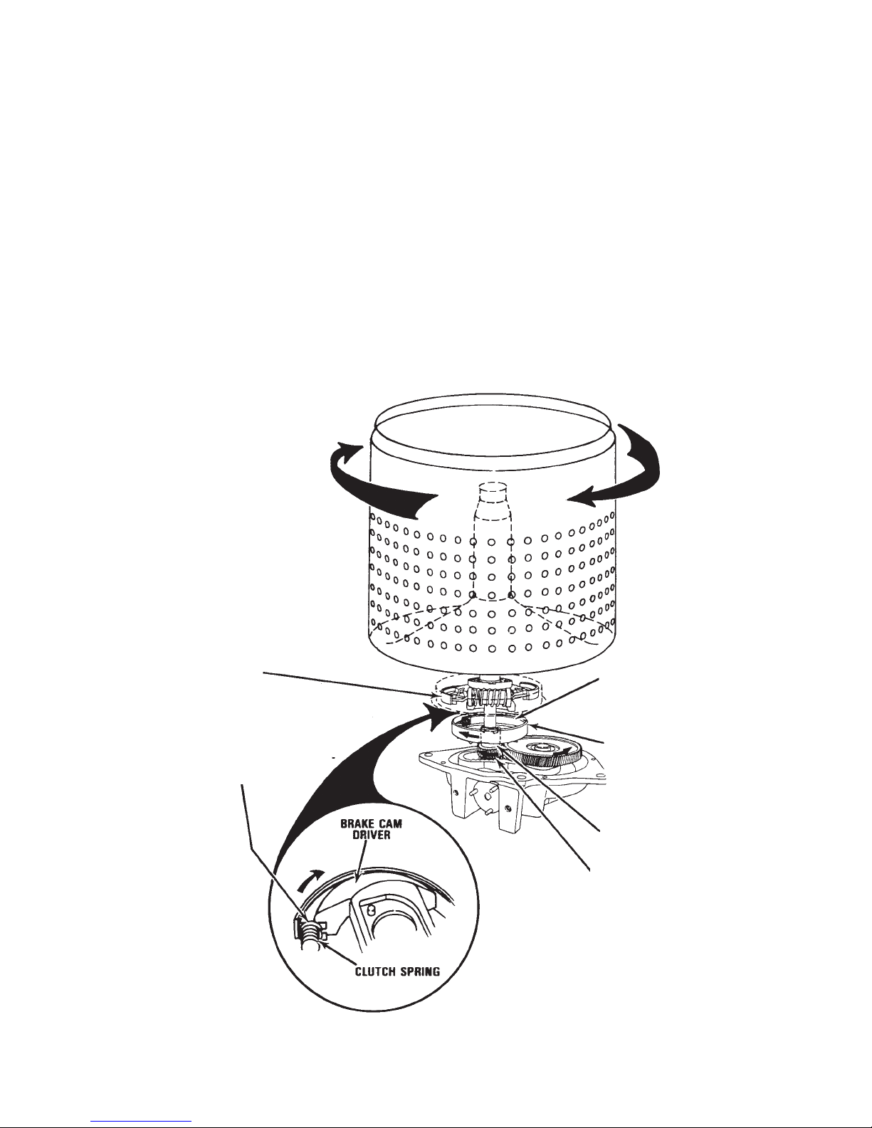
1. After the motor restarts, in the same clockwise direction, the transmission is reset for the spin
mode and the spin pinion begins to turn.
2. A clutch housing is mounted directly to the transmission spin pinion and begins to turn as well.
3. Inside the clutch housing is a clutch lining that is turned by the clutch housing by friction. The clutch
lining is an almost complete circular band that is cushioned with a spring to allow the clutch to slip
as the basket is coming up to speed. This slip prevents high torque loads on the motor and allows
the motor to bring this heavy load up to speed without overloading.
4. The clutch lining is designed to contact the basket drive brake cam which releases the basket
drive brakes during the spin cycle, allowing the basket drive to turn freely .
5. The basket drive is connected to the basket with a drive block and nut. The turning basket drive
causes the basket to begin to spin.
6. As the basket gets up to its full spin speed, the clutch slippage is gradually reduced until the clutch,
basket drive and basket are being driven as if they were one unit.
Fig. 2-16
Brake Shoe
Clutch Tab
Clutch Lining
Clutch Housing
Spin Pinion
Spin Pinion
Gear
13

-- NOTES --
14
Section One - Part C
COMPONENT ACCESS
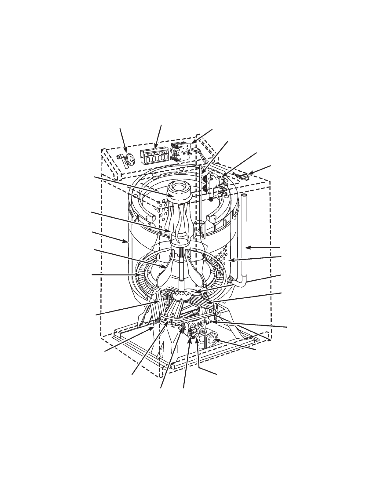
COMPONENT LOCATION
FABRIC
SOFTENER
DISPENSER
MANUAL
LINT FILTER
(if equipped)
TUB
AGITATOR
MAGICCLEAN
LINT FIL TER
(if equipped)
TUB
SUPPORT
WATER
LEVEL
SWITCH
PUSH-BUTTON
SWITCH
TIMER
PRESSURE DOME TUBE
FILL V AL VE
LID SWITCH
BLEACH
DISPENSER
HOSE
BASKET
FILTER VANES
(UNDER AGITATOR
PLATE)
SUSPENSION
PLATE
SPRING
SPRING BRACKET
GEARCASE
CAPACITOR
DRAIN
PUMP
CENTRIFUGAL
SWITCH
DRIVE
MOTOR
Fig. 3-1
15
! W ARNING
ELECTRIC SHOCK HAZARD
Disconnect the washer from the electrical power outlet
before performing any service or repairs.
Replace all panels before operating.
Failure to follow these instructions could result in death or electrical shock.
ACCESSING COMPONENTS IN THE CONSOLE
A number of critical components can be accessed from inside the control console. These components
are:
1. Timer
2. Push-button Switch Assembly
3. Water Level Switch
Servicing Components in the Console
1. Remove the two Phillips-head screws securing the front corners of the console to the washer
top.
2. Tip the console back on the hinges that secure the top of the console to the washer back.
(Fig. 3-2)
HINGE
HINGE
Fig. 3-2
16

Removing the Timer
There are two types of timers. One can be identified by a plastic body. The other has a metal body.
Plastic Body
NOTE:DO NOT ATTEMPT TO REMOVE THE TIMER KNOB BY PULLING FROM
THE FRONT. Doing so will damage the split shaft and require replacing the
entire timer assembly.
1. To remove the timer knob, push the knob in from the front.
2. At the back of the timer, pull the black tab out approximately 3/16”, then pull the timer knob
off the shaft.
BLACK T AB
Fig. 3-3
3. Slide the timer dial from the timer hub.
4. Unplug the wiring harness connector from the timer assembly terminals.
5. Remove the one (1) Hex-head screw securing the left side of the timer assembly to the console
mounting plate. Then lift the left side and slide the tabs at the right side of the timer assembly
from the console mounting plate.
MOUNTING SCREW
Fig. 3-4
17
Metal Body
1. To remove the timer knob, push the knob
in from the front and unscrew it from the
timer shaft.
(Fig. 3-5)
2. Slide the timer dial from the timer hub.
3. Remove the two (2) Hex-head screws
securing the timer assembly to the console
mounting plate.
4. Unplug the wiring harness connector from
the timer assembly terminals.
Fig. 3-5
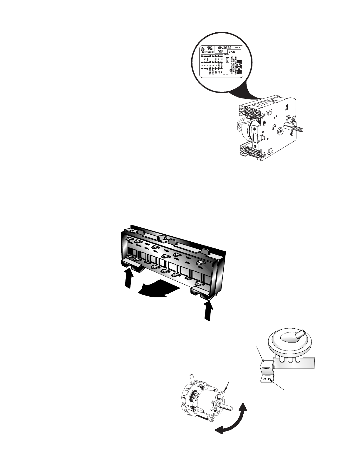
Removing the Push-Button Assembly
1. Unplug the wiring harness connectors from the switch assembly terminals using a pair of
needlenose pliers.
2. Press in the the two (2) tabs at the bottom of the switch assembly. Then, lift the bottom of the
switch assembly up and lift it away from the console mounting plate.
(Fig. 3-6)
Fig. 3-6
PUSH
IN
TIP UP
and
LIFT OUT
Removing the Water Level Switch
1. Pull the knob off of the switch shaft.
2. Unplug the wiring harness connector from
the switch assembly terminals and remove
pressure switch tubing.
3. Remove the Hex-head screw securing the
water level switch mounting bracket to the
console mounting plate
depress tab and rotate the switch 90°and
pull it from the console mounting plate.
(Fig. 3-7-B)
(Fig. 3-7-A)
OR
PUSH
IN
Fig. 3-7-B
MOUNTING
BRACKET
Fig. 3-7-A
DEPRESS
TAB
MOUNTING
HOLES
ROTA TE 90°
TO REMOVE
18
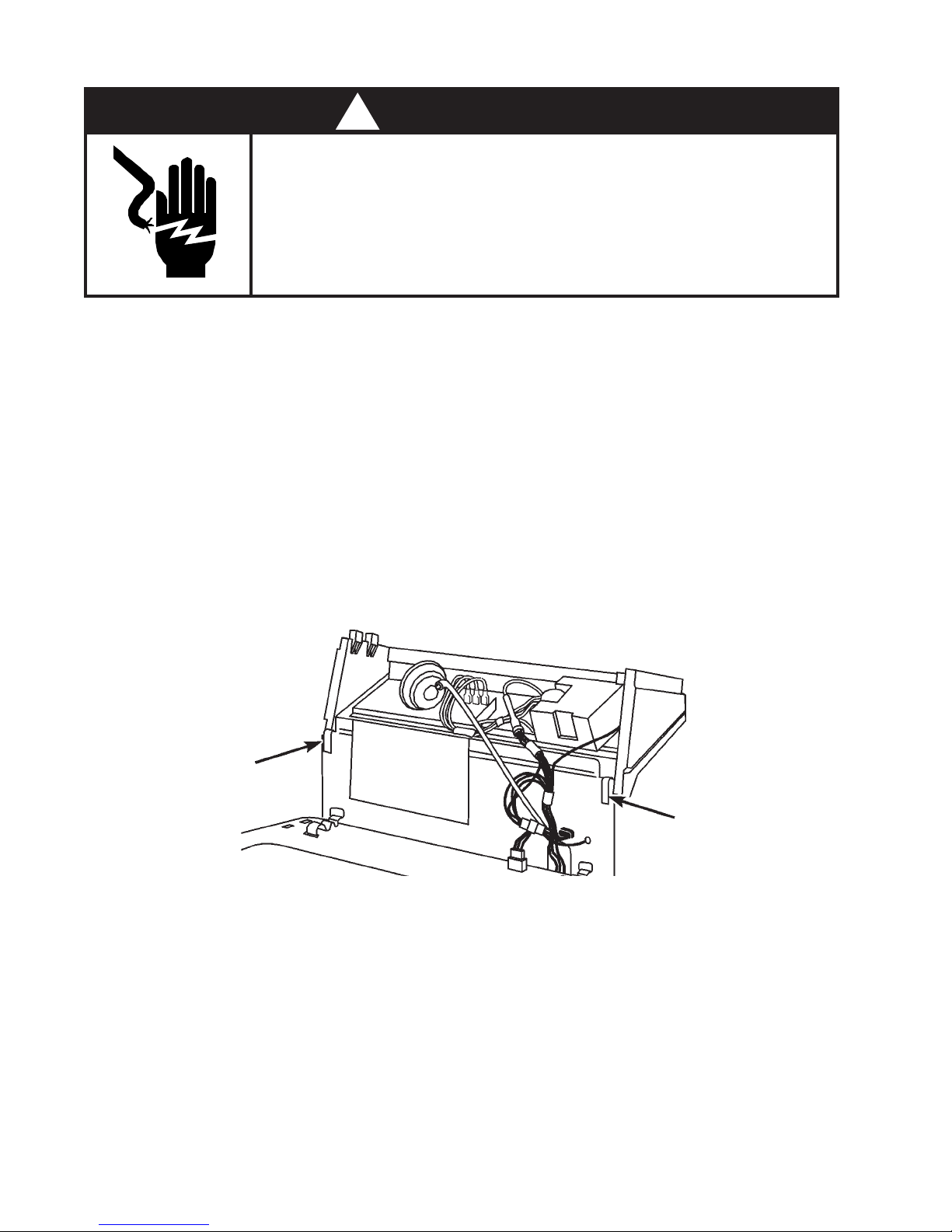
ACCESSING COMPONENTS INSIDE THE W ASHER CABINET
Components inside the washer cabinet can be accessed by completely removing the outer cabinet as
one unit. Refer to
Figure 3-8
1. Remove the console mounting screws and tilt the console into the service position.
2. Unplug the lid switch harness connector from the receptacle in the washer top.
3. Remove the cabinet mounting clips by placing the flat blade of a screwdriver in the clip as
shown in
Figure 3-8, Inset 1
CLIP
for the following instructions.
.
INSET 1
Fig. 3-8
CLIP
4. Remove the cabinet by tilting it forward and pulling it away from the washer.
Fig. 3-9
CABINET
NOTE:If necessary, the washer can be operated
in all cycles with the cabinet removed.
Install a jumper wire in the lid switch
harness connector as shown.
(Fig. 3-10)
GRAY
Fig. 3-10
VIOLET
(Fig. 3-9)
JUMPER
WIRE
IMPORTANT: Use extreme caution when
operating the washer with
the cabinet removed.
HARNESS
CONNECTOR
19
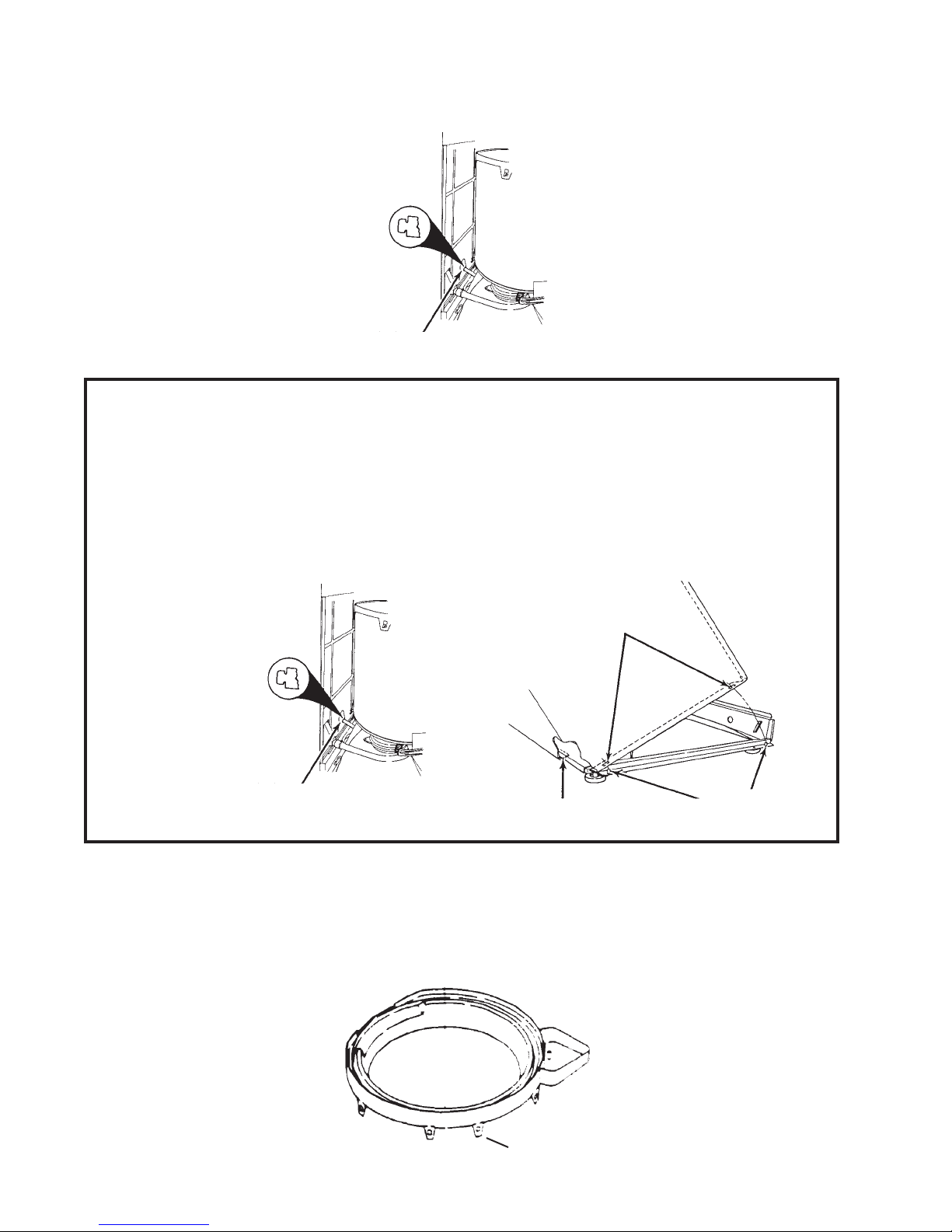
5. The rear panel can be tilted back for additional access to components at rear of machine by
twisting the rear panel support 90°, and then tilting the rear panel back.
REAR P ANEL SUPPORT
(Fig. 3-11)
Fig. 3-11
REASSEMBLY NOTES
When reassembling the cabinet make sure the following steps are taken:
1. When reinstalling the rear panel support, press in on the rear panel and rotate the support
to lock the panel in position.
2. The cabinet front flange must be under the washer base.
3. Holes in the cabinet side flange must be placed over the tabs in the washer base.
(Fig. 3-13-B)
(Fig. 3-12)
(Fig. 3-13-A)
Fig. 3-12
REAR P ANEL SUPPORT
Fig. 3-13
A
B
TABS
SERVICING THE TUB AND BASKET
1. To service the tub and basket, the cabinet must be removed.
2. If it is necessary to remove the inner basket, begin by removing the tub ring by unsnapping the
slots from the tabs on the tub. There are a total of eight tabs, one of which is a locator tab and
has a narrower slot than the others.
Fig. 3-14
(Fig. 3-14)
LOCAT OR TAB
20
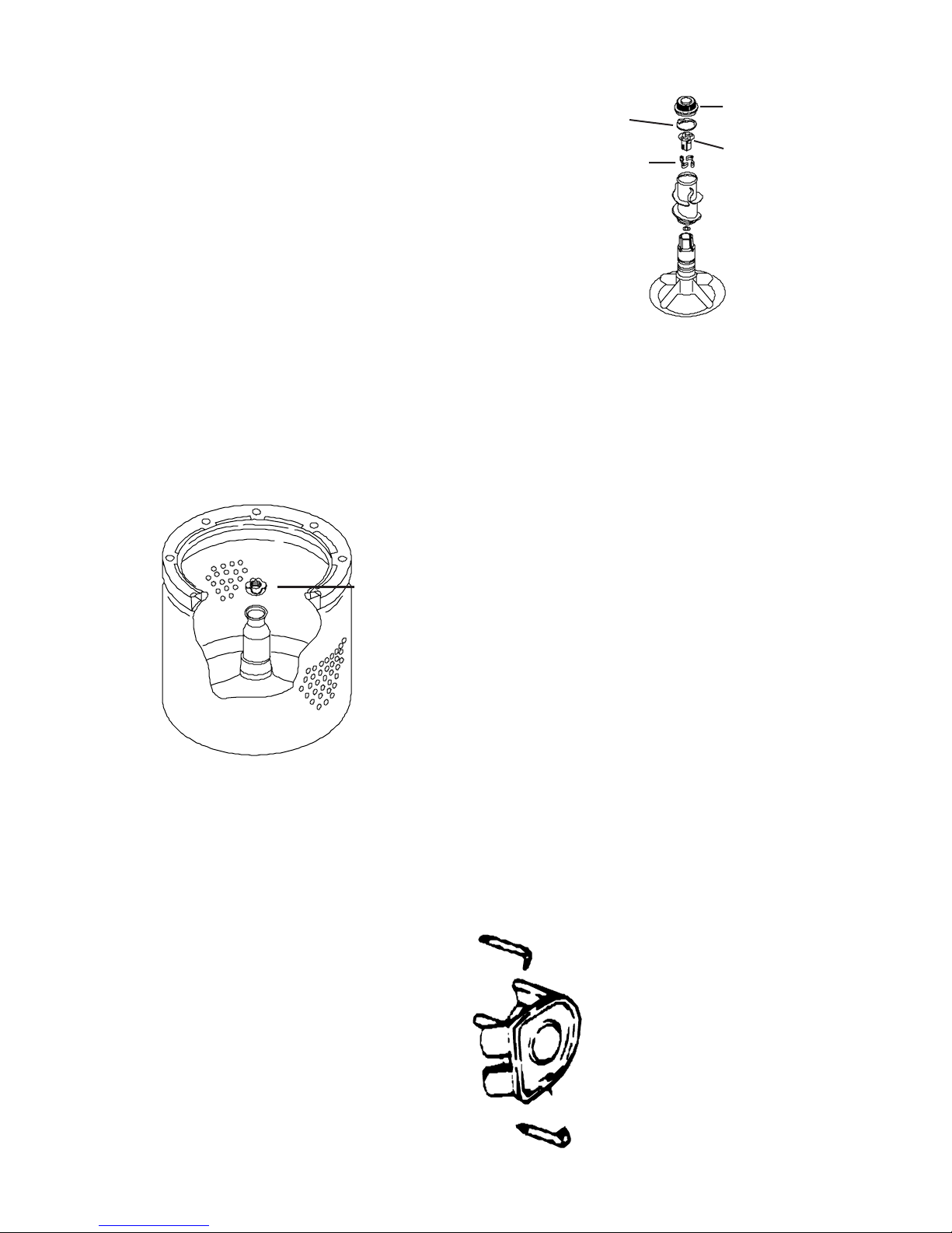
3. The Surgilator Agitator is removed by first
pulling off the agitator cap and inner cap.
Then unscrew the 7/16” bolt found under the cap and pull straight up on the twopiece agitator assembly. The clutch and
clutch dogs that provide the Surgilator action are found in the upper portion of the
agitator assembly.
(Fig. 3-15)
Inner Cap
Clutch Dogs
Agitator Cap
Clutch
Fig. 3-15
4. Complete the removal of the basket by
loosening the spanner nut on the spin tube
and expand the drive block with a wide
bladed screw driver .
(Fig. 3-16)
The basket can now be lifted straight up and out
of the tub.
Spanner Nut
Fig. 3-16
5. The tub assembly is secured to the tub
SUSPENSION
PLATE
BASE
support at three locations. There are two
screws, a suspension spring and a locating tab at each of these locations.
(Fig. 3-17)
SUSPENSION
SPRING
BRACKET
SPRING
Fig. 3-17
SERVICING THE DRIVE MOT OR AND PUMP
The drive motor and pump can be accessed by removing the cabinet. The pump is a sealed unit and
cannot be serviced. It should be replaced if it does not operate properly . The pump engages the drive
motor directly and is held in place by two retainer clips.
Fig. 3-18
(Fig. 3-18)
21
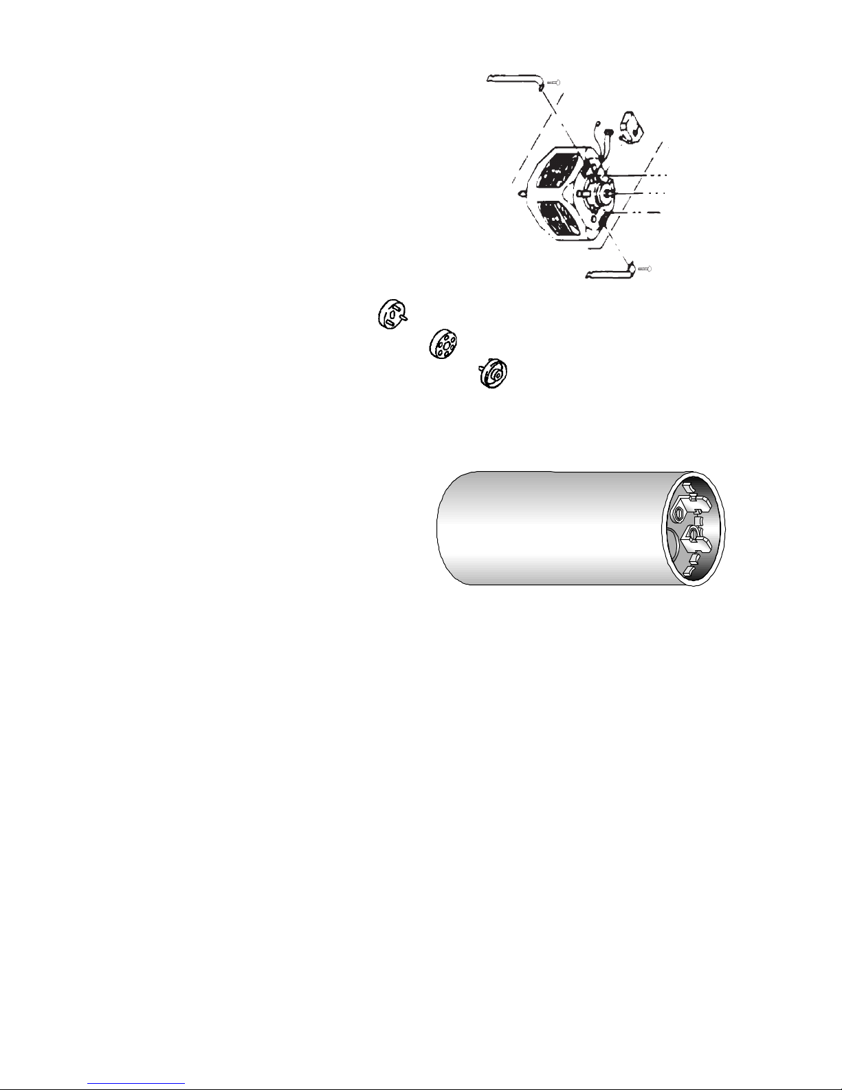
The motor of the Whirlpool Direct Drive Washer
is a reversing type, running in one direction for
agitation and in the other direction for drain and
spin. The motor is held in place by two retaining
clips and is coupled to the gearcase with two
three-prong couplers and an isolation coupler.
(Fig. 3-1)
MOTOR COUPLER
The motor coupler serves as a cushion
between the motor and gearcase and a
safeguard to protect the motor in the
event of a binding of the gearcase.
The coupler ends can be removed by
prying the outer pieces from the motor
and gearcase. If service to any of the
pieces is required, they must all be replaced.
ST ART CAP ACITOR
Fig. 3-19
Fig. 3-20
In older models the motor start capacitor is
located in the console.
is attached to the motor.
Figure 3-21
is a typical capacitor .
In newer models it
Fig. 3-21
SERVICING THE FRICTION PADS ON THE SUSPENSION PLATE AND
BASE ASSEMBLY
The tub support and brake assembly are attached to the suspension plate, which rests on the base
plate. This allows the tub and basket assembly to move in a gimbaling action.
The suspension plate and base assembly have friction resistance pads that provide protection between the metal assemblies.
1. Remove the outer cabinet from the washer.
2. Disconnect the wiring harness plug from the drive motor terminals.
3. Disconnect the tub outlet hose from the tub.
4. Remove the pump and motor.
5. Remove the gearcase. (See next page)
6. Lift the entire tub, basket and tub support out as one unit.
The pads on the suspension plate are now accessible for replacement.
7. Lift the suspension plate from the base assembly.
The pads on the base assembly are now accessible for replacement.
22
 Loading...