

Page 1

INSTALLATION INSTRUCTIONS
ELECTRIC DRYER
Table of Contents ............................................................................................... 2
IMPORTANT: Save for local electrical inspector’s use.
3397627C
Page 2
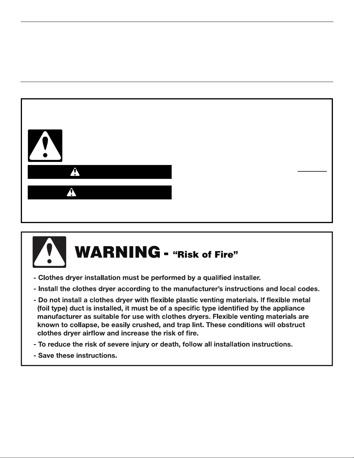
TABLE OF CONTENTS
DRYER SAFETY .........................................................................2
INSTALLATION INSTRUCTIONS ............................................... 4
Tools and Parts ........................................................................ 4
Location Requirements ............................................................ 4
Electrical Requirements ........................................................... 5
Electrical Connection ............................................................... 6
Venting Requirements ..............................................................7
Plan Vent System ..................................................................... 7
Install Vent System ..................................................................8
Install Leveling Legs ................................................................ 8
Conect Vent .............................................................................9
Level Dryer ............................................................................... 9
Check Operation ...................................................................... 9
Change Door Swing ............................................................... 10
DRYER SAFETY
Your safety and the safety of others are very important.
We have provided many important safety messages in this manual and on your appliance. Always read and obey all safety
messages.
This is the safety alert symbol.
This symbol alerts you to potential hazards that can kill or hurt you and others.
All safety messages will follow the safety alert symbol and either the word “DANGER” or “WARNING.”
These words mean:
You can be killed or seriously injured if you don't immediately
DANGER
WARNING
follow instructions.
You
can be killed or seriously injured if you don't
instructions.
follow
All safety messages will tell you what the potential hazard is, tell you how to reduce the chance of injury, and tell you what can
happen if the instructions are not followed.
2
Page 3

3
Page 4
INSTALLATION INSTRUCTIONS
Tools and Parts
Gather the required tools and parts before starting installation.
Read and follow the instructions provided with any tools listed
here.
Tools needed:
■ Flat-blade screwdriver
■ Phillips screw driver
■ Adjustable wrench that
opens to 1" (25mm) or
hex-head socket wrench
(for adjusting dryer feet)
■ Level
Parts supplied:
Parts package is located in dryer drum. Check that all parts
are included.
4 Leveling legs
■ Utility knife
■ 1/4" socket wrench or
1/4" nut driver
■ Vent clamps
■ Caulk gun and caulk (for
installing new exhaust
vent)
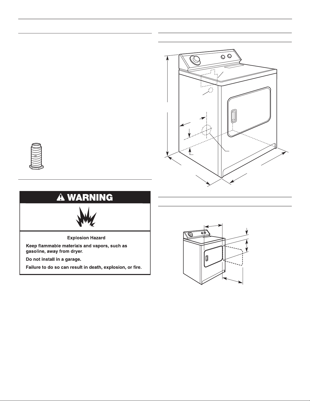
Dryer Dimensions
power supply
423/8"*
(1076 mm)
cord/cable
1
14
(368 mm)
28" max.
(711 mm)
opening
/2"
6"
(152 mm)*
terminal block
cover
dryer
exhaust
vent
29"
(737 mm)
Location Requirements
IMPORTANT: Observe all governing codes and ordinances.
■ Check code requirements: Some codes limit or do not permit
installation of clothes dryers in garages, closets, or sleeping
quarters. Contact your local building inspector.
■ Make sure that lower edges of the cabinet, plus the back and
bottom sides of the dryer, are free of obstructions to permit
adequate clearance of air openings for combustion air. See
“Recessed Area and Closet Installation Instructions” for
minimum spacing requirements.
Door Clearance
*from oor with
dryer feet extended
1" (25 mm)
3
22
/4"
(578 mm)
223/4"
(578 mm)
7
/8"
3
(98 mm)
(486 mm)
19
1
/8"
NOTE: The dryer must not be installed in an area where it will be
exposed to water and/or weather.
4
Page 5

Recessed Area and Closet Installation Instructions
This dryer may be installed in a recessed area or closet. For
recessed area and closet installations, minimum clearances
can be found on the serial tag on the dryer.
The installation spacing is in inches and is the minimum
allowable. Additional spacing should be considered for
ease of installation, servicing, and compliance with local
codes and ordinances.
If closet door is installed, the minimum unobstructed air
opening in the top and bottom is required. Louvered doors
with equivalent air openings are acceptable.
The dryer must be exhausted outdoors.
No other fuel-burning appliance may be installed in the same
closet as the dryer.
Minimum Installation Clearances
14" max.
(356 mm)
18"*
Closet
door
(457 mm)
Electrical Requirements
Important: Observe all governing codes and ordinances.
A two-wire plus separate ground wire, or a 3-wire, single-phase
230-volt, 50-Hz, AC only, electrical supply is required on a
separate 15-amp circuit, fused on both sides of the line. A timedelay fuse or circuit breaker is recommended.
It is the personal responsibility and obligation of the customer
to contact a qualied electrician to assure that the electrical
installation is adequate and is in conformance with all local
codes and ordinances.
0"
(0 mm)
0"
(0 mm)
1"
(25 mm)
4"
(102 mm)
Recessed front view Closet side view
Additional clearances for wall, door, and oor moldings may be required or if
external exhaust elbow is used.
3" (76 mm)
2
48"
(310 cm2)*
Front
View
24"
2
Closet
Door
(155 cm2)*
3" (76 mm)
Louvered doors with equivalent air openings are acceptable.
*Opening is the minimum for a closet door.
If codes permit and a separate grounding wire is used, it is
recommended that a qualied electrician determine that the
grounding path is adequate.
This dryer is equipped with a power supply cord. To minimize
possible shock hazard, the cord must be plugged into a mating
wall receptacle.
If your electrical requirements are different, contact your
authorized Whirlpool service center or a qualied electrician.
5
Page 6

Direct Wire
It is recommended that installation should be done by a qualied
electrician.
This dryer can be connected directly to the fused disconnect or
circuit breaker box with two-wire or three-wire exible, armored
or non-metallic sheathed copper cable (with ground wire). Do Not
use two-wire with bare ground wire. All current-carrying wires
must be insulated.
A conduit connector must be installed at each end of the power
supply cable (at the dryer and at the junction box.) USE ONLY
10-GAUGE SOLID COPPER WIRE. DO NOT USE ALUMINUM
WIRE. Allow 4 ft (1.22 m) of slack in the line so the dryer can be
moved if servicing is ever necessary.
Recommended Ground Method
■ It is your responsibility to contact a qualied electrical installer
to ensure that the electrical installation is adequate and in
conformance with the National Electrical Code, ANSI/NFPA
70, latest edition, and all local codes and ordinances.
Electrical Connection
Plug power supply cord into the grounded outlet or connect
direct wire to power supply. Turn power supply on.
6
Page 7

Venting Requirements
WARNING: To reduce the risk of re, this dryer MUST BE
EXHAUSTED OUTDOORS.
Elbows:
Plan installation to use the fewest number of elbows and turns.
Good Better
Clamps:
■ Use clamps to seal all joints.
■ Exhaust vent must not be connected or secured with screws
or other fastening devices which extend into the interior of the
vent and catch lint. Do not use duct tape.
IMPORTANT: Observe all governing codes and ordinances.
Dryer vent must not be connected into any gas vent,
chimney, wall, ceiling, attic, crawlspace, or a concealed space
of a building.
If using an existing vent system
■ Clean lint from the entire length of the system and make sure
exhaust hood is not plugged with lint.
■ Replace any plastic or metal foil vent with rigid heavy metal
vent or exible metal vent.
■ Review Vent System Chart. Modify existing vent system if
necessary to achieve the best drying performance. Only rigid
or exible metal vent shall be used for exhausting.
If this is a new vent system
Vent material
■ Use a heavy metal vent. Do not use plastic or metal foil vent.
■ 4" (102 mm) heavy metal vent and clamps must be used.
4" (102 mm) heavy metal exhaust vent
Rigid metal vent
■ Recommended for best drying performance and to avoid
crushing and kinking.
Flexible metal vent
■ Must be fully extended and supported when the dryer is in it’s
nal location.
■ Remove excess to avoid sagging and kinking that may result
in reduced airow and poor performance.
■ Do not install exible metal vent in enclosed walls, ceilings, or
oors.
Exhaust
Recommended hood styles. Acceptable hood style.
B
4"
(102 mm)
A
4"
(102 mm)
4"
(102 mm)
A. Louvered hood style
B. Box hood style
C. Angled hood style is acceptable
■ An exhaust hood should cap the vent to keep rodents and
C
2
½"
(64 mm)
insects from entering the home or business.
■ Exhaust hood must be at least 12" (305 mm) from the ground
or any object that may be in the path of the exhaust (such as
owers, rocks, or bushes).
■ Do not use an exhaust hood with a magnetic latch.
■ A four-inch outlet hood is preferred. However, a 2
1
⁄2" (64 mm)
outlet exhaust hood may be used. A 21⁄2" (64 mm) outlet
creates greater back pressure than other hood types. For
permanent installation, a stationary vent system is required.
Plan Vent System
Determine vent path:
■ Vent outlet is located at the center of the bottom dryer back.
■ The vent can be routed up, down, left, right, behind the dryer,
or straight out the back of the dryer.
■ When using elbows or making turns, allow as much room as
possible.
■ Bend vent gradually to avoid kinking.
7
Page 8

Vent System Length
Maximum length of vent system depends upon the type of vent
used, number of elbows, and type of exhaust hood. The
maximum length for both rigid and exible vent is shown in the
chart.
Vent System Chart
Number of
90° elbows
Type
of vent
Box/louvered
hoods
Angled
hoods
Install Leveling Legs
0
1
2
3
4
For vent systems not covered by the vent specication chart, see
Whirlpool Service Manual, “Exhausting Whirlpool Dryers,” Part
No. LIT603197, available from your Whirlpool parts distributor.
If dryer is installed in a conned area, such as a bedroom,
bathroom, or closet, provision must be made for enough
air for combustion and ventilation. (Check governing codes
and ordinances.) See “Recessed Area and Closet Installation
Instructions” in the “Location Requirements” section.
Rigid metal
Rigid metal
Rigid metal
Rigid metal
Rigid metal
64 ft. (20 m)
54 ft. (16.5 m)
44 ft. (13.4 m)
35 ft. (10.7 m)
27 ft. (8.2 m)
58 ft. (17.7 m)
48 ft. (14.6 m)
38 ft. (11.6 m)
29 ft. (8.8 m)
21 ft. (6.4 m)
Install Vent System
1. Install exhaust hood. Use caulking compound to seal exterior
wall opening around exhaust hood.
12" min.
(305 mm)
1. Remove tape from dryer cabinet. Open dryer door and
remove tape from dryer drum. (Not all dryer drums are
taped.) Remove drying rack, if included. Turn dryer drum
counterclockwise to make sure all tape was removed. Wipe
drum with damp cloth to remove any dust.
2. Take two cardboard corners from dryer carton and place
them on oor in back of dryer. Firmly grasp body of dryer and
gently lay it on its back on the cardboard corners.
12" min.
(305 mm)
2. Connect exhaust vent to hood. Vent must t inside exhaust
hood. Secure vent to exhaust hood with vent tape.
3. Run exhaust vent to dryer location. Use the straightest path
possible. Avoid 90º turns. Use vent tape to seal all joints.
8
diamond
marking
3. Start to screw legs into holes by hand. Use an adjustable
wrench or 1" (25 mm) hex-head socket wrench to nish
turning legs until you reach the ridge with the diamond
marking.
4. Place a carton corner post from dryer packaging under each
of the 2 dryer back corners. Stand the dryer up. Slide the
dryer on the corner posts until it is close to its nal location.
Leave enough room to connect the exhaust vent.
Page 9

Connect Vent
1. Using a 4" (102 mm) clamp, connect vent to exhaust outlet
in dryer. If connecting to existing vent, make sure the vent is
clean. Dryer vent must t over dryer exhaust outlet and inside
exhaust hood. Check that vent is secured to exhaust hood
with a 4" (102 mm) clamp.
102 mm (4")
clamp
102 mm (4")
clamp
2. Move dryer into nal position.
3. Once exhaust vent connection is made, remove corner posts
and cardboard.
Check Operation
1. Check that you:
■ Did not skip any steps.
■ Installed all parts.
■ Properly installed dryer legs.
■ Leveled dryer.
■ Have all the tools you started with.
2. Plug power supply cord into grounded outlet or connect
direct wire to power supply. Turn power supply on.
3. Read the “Use and Care Guide” to fully understand your
new dryer. Select a full heat cycle (not the air cycle) and start
dryer. After ve minutes, open dryer door. You should feel
heat inside dryer.
If the dryer will not start, check the following:
■ Electrical supply is connected
■ House fuse is intact and tight, or circuit breaker
has not tripped.
■ Dryer door is closed.
■ Controls are set in a running or “On” position.
■ Start button has been pushed rmly.
Level Dryer
Check levelness of dryer by placing a level on top of dryer, rst
side to side, then front to back.
If the dryer is not level, prop up the dryer using a wood block.
Use a wrench to adjust the legs up or down and check again for
levelness.
If legs are not long enough to level dryer, order Extended Dryer
Feet Kit, Part No. 279810 (sold two legs per kit), from your dealer.
If dryer makes an unusual noise, check that the dryer is level.
9
Page 10

Change Door Swing
If not reversing door swing, skip ahead to “Level and Exhaust the
Dryer” steps.
Avoid scratching or chipping paint.
A
E
D
C
B
1. Place a large towel or soft cloth (A) on top of dryer to avoid
damaging the surface.
2. Open dryer door. Remove bottom screws from cabinet
side of hinges (B). Loosen (do not remove) top screws from
cabinet side of hinges.
3. Lift door until top screws in cabinet are in large part of hinge
slot. Pull door forward off screws. Set door (handle side up)
on top of dryer. Remove top screws from cabinet.
4. Remove screws attaching hinges to door.
5. Remove screws at top, bottom, and side of door. Holding
door over towel on dryer, grasp sides of outer door and
gently lift to separate it from inner door. Do NOT pry apart
with putty knife. Do NOT pull on door seal or plastic door
catches.
7. Attach door hinge to door so large part of hinge slot is at
bottom of hinge.
8. Gently remove 4 hinge hole plugs (C) on left side of cabinet.
Insert plugs in hinge holes on right side of cabinet.
9. Insert screws in bottom holes on left side of cabinet. Tighten
screws halfway. Position door so large end of door hinge
slot is over screws. Slide door up so screws are in bottom
of slots. Tighten screws. Insert and tighten top screws in
hinges.
10. Remove door strike (D) from cabinet. Remove door strike
plug. Insert door strike in new hole and secure with screw.
Insert door strike plug in original door strike hole and secure
with screw.
11. Close door and check that door strike aligns with door catch
(E). If door does not close completely, slide door catch left or
right within slot until strike snaps into catch.
6. Turn and reattach outer door panel to inner door panel so
handle is on the side where hinges were just removed. Be
sure to keep cardboard spacer centered between doors.
10
Page 11

Notes
11
Page 12

3397627C
© 2011 3/11
12
All rights reserved Printed in U.S.A.
 Loading...